JP2009106984A - Welding starting method for two wire welding - Google Patents
Welding starting method for two wire welding Download PDFInfo
- Publication number
- JP2009106984A JP2009106984A JP2007283011A JP2007283011A JP2009106984A JP 2009106984 A JP2009106984 A JP 2009106984A JP 2007283011 A JP2007283011 A JP 2007283011A JP 2007283011 A JP2007283011 A JP 2007283011A JP 2009106984 A JP2009106984 A JP 2009106984A
- Authority
- JP
- Japan
- Prior art keywords
- welding
- wire
- filler wire
- filler
- base material
- Prior art date
- Legal status (The legal status is an assumption and is not a legal conclusion. Google has not performed a legal analysis and makes no representation as to the accuracy of the status listed.)
- Pending
Links
- 238000003466 welding Methods 0.000 title claims abstract description 138
- 238000000034 method Methods 0.000 title claims abstract description 20
- 239000000945 filler Substances 0.000 claims abstract description 69
- 238000013459 approach Methods 0.000 claims abstract description 5
- 238000010304 firing Methods 0.000 claims description 2
- 239000000463 material Substances 0.000 abstract description 21
- 238000001514 detection method Methods 0.000 abstract description 20
- 239000011324 bead Substances 0.000 abstract description 13
- 230000007547 defect Effects 0.000 abstract description 4
- 239000000956 alloy Substances 0.000 description 1
- 229910045601 alloy Inorganic materials 0.000 description 1
- 230000015572 biosynthetic process Effects 0.000 description 1
- 238000005336 cracking Methods 0.000 description 1
- 230000007423 decrease Effects 0.000 description 1
- 238000010586 diagram Methods 0.000 description 1
- 230000000694 effects Effects 0.000 description 1
- 230000002349 favourable effect Effects 0.000 description 1
- 230000007704 transition Effects 0.000 description 1
Images
Landscapes
- Arc Welding In General (AREA)
Abstract
Description
本発明は、消耗電極ワイヤとフィラーワイヤとを用いた2ワイヤ溶接の溶接開始方法に関する。 The present invention relates to a welding start method for two-wire welding using a consumable electrode wire and a filler wire.
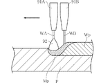
消耗電極ワイヤとフィラーワイヤとを用いた2ワイヤ溶接は、溶接速度を向上させ、かつ溶接ビードの美観を良好とするのに適した溶接方法として知られている(たとえば、特許文献1)。図3は、従来の2ワイヤ溶接の一例を示している。同図に示された2ワイヤ溶接には、コンタクトチップ91A,91Bを備える溶接トーチが用いられる。コンタクトチップ91Aを通して、ワイヤWAが供給される。また、ワイヤWAに対して溶接方向後方から、コンタクトチップ91Bを通してフィラーワイヤWBが供給される。
Two-wire welding using a consumable electrode wire and a filler wire is known as a welding method suitable for improving the welding speed and improving the appearance of the weld bead (for example, Patent Document 1). FIG. 3 shows an example of conventional two-wire welding. For the two-wire welding shown in the figure, a welding torch including
コンタクトチップ91Aは、溶接電源(図示略)に接続されている。この溶接電源は、コンタクトチップ91Aと溶接母材Pとの間に電圧を印加する。これにより、ワイヤWAから溶接母材Pに向かうアーク92が発生する。ワイヤWAは、アーク92の強さに応じた速度で、供給装置(図示略)から送給される。一方、フィラーワイヤWBは、アーク92によって生じた溶融池Mpに向けて送給装置(図示略)によって送給される。フィラーワイヤWBは、溶融池Mpの熱によって溶解される。この結果、溶融したワイヤWA、フィラーワイヤWB、および溶接母材Pが合金状態で凝固することにより、溶接ビードWpが形成される。このような2ワイヤ溶接によれば、溶接速度を比較的高速としても、溶接ビードWpが極端に痩せてしまうことを防止できる。また、アークを発生させない状態でフィラーワイヤWBを送給することにより、溶接ビードWpの外観を良好にすることができる。
The
しかしながら、2ワイヤ溶接を開始するときには、溶接ビードWpの開始端が肉痩せなどの溶接欠陥とならないようにスムースに溶接を開始することが必要である。特に、アーク92の点弧によって形成され始めた溶融池MpにフィラーワイヤWBを正確に送給し始めることが重要である。フィラーワイヤWBの送給開始タイミングが早すぎると、溶融池Mpが形成されていない溶接母材PにフィラーワイヤWBが衝突してしまう。これは、フィラーワイヤWBの座屈や折損を生じるおそれがある。一方、フィラーワイヤWBの送給開始タイミングが遅すぎると、溶融池Mpが形成されたにもかかわらずフィラーワイヤWBが供給されない箇所ができてしまう。この箇所に形成された溶接ビードWpは極端に肉痩せすることとなり、割れの原因となってしまう。
However, when starting the two-wire welding, it is necessary to start the welding smoothly so that the starting end of the weld bead Wp does not become a welding defect such as thinning. In particular, it is important to start feeding the filler wire WB accurately to the molten pool Mp that has started to be formed by the ignition of the
本発明は、上記した事情のもとで考え出されたものであって、2ワイヤ溶接をスムースに開始するとともに、溶接ビードの開始端に溶接欠陥が生じることを防止することが可能な2ワイヤ溶接の溶接開始方法を提供することをその課題とする。 The present invention has been conceived under the circumstances described above, and it is possible to start 2-wire welding smoothly and to prevent a welding defect from occurring at the start end of the weld bead. It is an object of the present invention to provide a welding start method for welding.
本発明によって提供される2ワイヤ溶接の溶接開始方法は、消耗電極ワイヤと溶接対象物との間に電圧を印加することにより上記消耗電極ワイヤからアークを発生させながら溶接方向に進行させるとともに、上記消耗電極ワイヤに対して溶接方向後方からフィラーワイヤを供給する2ワイヤ溶接の溶接開始方法であって、上記フィラーワイヤと溶接対象物との間に電圧を印加した状態で、上記フィラーワイヤを上記溶接対象物に向けて接近させるステップと、上記フィラーワイヤと溶接対象物とが通電した以降に、上記フィラーワイヤの接近を停止するステップと、上記消耗電極ワイヤからのアーク点弧と上記消耗電極ワイヤおよび上記フィラーワイヤの溶接方向への進行を始めるステップと、上記フィラーワイヤを溶接対象物に向けて送給し始めるステップと、を有することを特徴としている。 The welding start method of the two-wire welding provided by the present invention advances in the welding direction while generating an arc from the consumable electrode wire by applying a voltage between the consumable electrode wire and the welding object. A welding start method of two-wire welding in which a filler wire is supplied to a consumable electrode wire from behind in the welding direction, and the filler wire is welded in a state where a voltage is applied between the filler wire and a welding object. A step of approaching the object, a step of stopping the approach of the filler wire after the filler wire and the welding object are energized, an arc firing from the consumable electrode wire, the consumable electrode wire, and Starting the progress of the filler wire in the welding direction and feeding the filler wire toward the object to be welded; It is characterized by having the steps of starting, the.
このような構成によれば、上記アークによって上記溶接対象物に形成された溶融池の直上に上記フィラーワイヤが位置したときに、確実に上記フィラーワイヤの送給を開始することができる。したがって、上記フィラーワイヤの送給開始タイミングが早すぎるために生じうる上記フィラーワイヤの座屈および折損や、上記フィラーワイヤの送給開始タイミングが遅すぎることによる溶接ビードの開始端の極端な肉痩せを防止することができる。 According to such a configuration, when the filler wire is positioned immediately above the molten pool formed on the welding object by the arc, feeding of the filler wire can be surely started. Therefore, the filler wire buckling and breakage that may occur because the filler wire feed start timing is too early, and the extreme thinning of the weld bead start end due to the filler wire feed start timing being too late. Can be prevented.
本発明のその他の特徴および利点は、添付図面を参照して以下に行う詳細な説明によって、より明らかとなろう。 Other features and advantages of the present invention will become more apparent from the detailed description given below with reference to the accompanying drawings.
以下、本発明の好ましい実施の形態につき、図面を参照して具体的に説明する。 Hereinafter, preferred embodiments of the present invention will be specifically described with reference to the drawings.
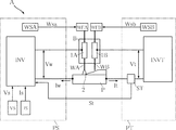
図1は、本発明に係る2ワイヤ溶接の溶接開始方法に用いられる溶接システムを示している。本実施形態の溶接システムAは、溶接トーチB、ワイヤ送給装置WFA,WFB、溶接電源PS、検出用電源PTを備えている。溶接システムAは、消耗電極ワイヤとしてのワイヤWAとフィラーワイヤWBとを用いた2ワイヤ溶接を行う。 FIG. 1 shows a welding system used in a welding start method for two-wire welding according to the present invention. The welding system A of this embodiment includes a welding torch B, wire feeding devices WFA, WFB, a welding power source PS, and a detection power source PT. The welding system A performs two-wire welding using a wire WA as a consumable electrode wire and a filler wire WB.
溶接トーチBは、たとえば略円筒形状のノズルであり、一般的にロボット(図示略)に装着されている。溶接トーチBは、コンタクトチップ1A,1Bを有している。コンタクトチップ1Aは、ワイヤWAが挿通可能な貫通孔を有しており、ワイヤWAと導通している。コンタクトチップ1Bは、フィラーワイヤWBが挿通可能な貫通孔を有しており、フィラーワイヤWBと導通している。溶接トーチBを用いた2ワイヤ溶接においては、ワイヤWAが溶接方向前方に位置し、フィラーワイヤWBが溶接方向後方に位置した状態で、溶接トーチBが上記ロボットによって溶接方向に移動される。
The welding torch B is, for example, a substantially cylindrical nozzle, and is generally attached to a robot (not shown). The welding torch B has
ワイヤ送給装置WFA,WFBは、それぞれワイヤWA,WBを送給するためのものであり、たとえばモータ(図示略)などの駆動源を有している。ワイヤ送給装置WFA,WFBは、溶接電源PSおよび検出用電源PTからの指令により、溶接条件にあった送給速度でワイヤWAおよびフィラーワイヤWBを送給する。 The wire feeding devices WFA and WFB are for feeding the wires WA and WB, respectively, and have a drive source such as a motor (not shown). The wire feeders WFA and WFB feed the wire WA and the filler wire WB at a feeding speed that meets the welding conditions in accordance with commands from the welding power source PS and the detection power source PT.
溶接電源PSは、ワイヤWAにアークを発生させるための電源であり、出力制御回路INV、溶接電圧設定回路VS、溶接電流設定回路IS、および送給速度設定回路WSAを備えている。出力制御回路INVは、コンタクトチップ1Aと溶接母材Pとに導通しており、これらの間に溶接電圧Vwを印加する。溶接電圧Vwが印加された状態でアーク2が発生すると、溶接電流Iwが流れる。出力制御回路INVには、溶接電圧設定回路VSから溶接電圧設定信号Vsが送られる。送給速度設定回路WSAは、ワイヤ送給装置WFAに送給速度設定信号Wsaを送る回路である。
The welding power source PS is a power source for generating an arc in the wire WA, and includes an output control circuit INV, a welding voltage setting circuit VS, a welding current setting circuit IS, and a feeding speed setting circuit WSA. The output control circuit INV is electrically connected to the
検出用電源PTは、フィラーワイヤWBが溶接母材Pに接触したことを検出するための電源であり、出力制御回路INVT、検出器ST、および送給速度設定回路WSBを備えている。出力制御回路INVTは、コンタクトチップ1Bと溶接母材Pとに導通しており、これらの間に検出電圧Vtを印加する。検出電圧Vtが印加された状態でフィラーワイヤWBと溶接母材Pとが接触すると、検出電流Itが流れる。検出器STは、検出電流Itが流れていることを検出するデバイスである。検出電流Itが流れたことを検出すると、検出器STは、溶接電源PSに対して検出信号Stを送る。送給速度設定回路WSBは、ワイヤ送給装置WFBに送給速度設定信号Wsbを送る回路である。
The power source PT for detection is a power source for detecting that the filler wire WB has contacted the welding base material P, and includes an output control circuit INVT, a detector ST, and a feed speed setting circuit WSB. The output control circuit INVT is electrically connected to the
次に、溶接システムAを用いた2ワイヤ溶接の溶接開始方法の一例について、図2を参照しつつ以下に説明する。 Next, an example of a welding start method of two-wire welding using the welding system A will be described below with reference to FIG.
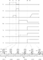
まず、時刻t0において、フィラーワイヤWBと溶接母材Pとの間に検出電圧Vtを印加する。次いで時刻t1において、同図(G1)に示すようにワイヤ送給装置WFBによりフィラーワイヤWBの送給を開始する。このときの送給速度Fwbは、定常溶接時よりも遅い速度としておく。 First, at time t0, a detection voltage Vt is applied between the filler wire WB and the welding base material P. Next, at time t1, feeding of the filler wire WB is started by the wire feeding device WFB as shown in FIG. The feeding speed Fwb at this time is set to a speed slower than that during steady welding.
次に、時刻t2において、同図(G2)に示すようにフィラーワイヤWBが溶接母材に接触すると、検出電流Itが流れ、検出電圧Vtが短絡電圧に低下する。検出電流Itが流れたことを検出器STが検出する。送給速度設定回路WSBからの送給速度設定信号Wsbによってワイヤ送給装置WFBがフィラーワイヤWBの送給を停止する。これにより、フィラーワイヤWBは溶接母材Pに接触した状態に保たれる。 Next, when the filler wire WB comes into contact with the welding base material at time t2, as shown in (G2), the detection current It flows and the detection voltage Vt decreases to the short circuit voltage. The detector ST detects that the detection current It has flowed. The wire feeding device WFB stops feeding the filler wire WB by the feeding speed setting signal Wsb from the feeding speed setting circuit WSB. As a result, the filler wire WB is kept in contact with the welding base material P.
また、検出器STからの検出信号Stが溶接電源PSの出力制御回路INVに送られる。出力制御回路INVはあらかじめ設定された時間が経過した後に、時刻t3において検出電圧Vtの印加を停止するとともに、ワイヤWAと溶接母材Pとの間に溶接電圧Vwを印加する。これと同時に、同図(G3)に示すようにワイヤWAの送給を開始する。このときの送給速度Fwaは、定常溶接時よりも遅い速度としておく。 Further, the detection signal St from the detector ST is sent to the output control circuit INV of the welding power source PS. The output control circuit INV stops applying the detection voltage Vt at time t3 after a preset time has elapsed, and applies the welding voltage Vw between the wire WA and the welding base material P. At the same time, the feeding of the wire WA is started as shown in FIG. The feeding speed Fwa at this time is set to a speed slower than that during steady welding.
ワイヤWAが溶接母材Pに接近すると、時刻t4において同図(G4)に示すように、アーク2が点弧し、溶接電流Iwが流れ始める。アーク2によって溶接母材Pには溶融池Mpが形成され始める。また、溶接電流Iwが流れ始めたことをもって、溶接トーチBを溶接母材Pに対して溶接速度Fで移動させ始め、ワイヤWAの送給速度Fwaを定常溶接時の速度に増速させる。
When the wire WA approaches the welding base material P, the
時刻t4においては、フィラーワイヤWBはいまだ溶融池Mpに到達していない。ワイヤWAとフィラーワイヤWBの距離、および溶接速度Fが既知であることにより、時刻t4からフィラーワイヤWBが溶融池Mpに到達するまでに要する時間が算出できる。すなわち、時刻t4からこの算出された時間を経過させた時刻t5に、同図(G5)に示すようにフィラーワイヤWBが溶融池Mpに到達する。このタイミングでワイヤWBの送給を再び開始する。このとき、たとえば送給速度Fwbを0から定常溶接時の速度まで徐々に増速させる。以上の溶接開始方法を経ることにより、同図(G6)に示すように2ワイヤ溶接の定常状態への移行が完了し、溶接ビードWpが連続的に形成される。 At time t4, the filler wire WB has not yet reached the molten pool Mp. Since the distance between the wire WA and the filler wire WB and the welding speed F are known, the time required from the time t4 until the filler wire WB reaches the molten pool Mp can be calculated. That is, at time t5 when the calculated time has elapsed from time t4, filler wire WB reaches molten pool Mp as shown in FIG. At this timing, the feeding of the wire WB is started again. At this time, for example, the feeding speed Fwb is gradually increased from 0 to the speed during steady welding. By passing through the above welding start method, as shown to the same figure (G6), the transition to the steady state of 2 wire welding is completed, and the weld bead Wp is formed continuously.
次に、本発明に係る2ワイヤ溶接の溶接開始方法の作用について説明する。 Next, the effect | action of the welding start method of 2 wire welding which concerns on this invention is demonstrated.
本実施形態によれば、フィラーワイヤWBが溶融池Mpの直上に位置したとき(時刻t5)に、確実にフィラーワイヤWBの送給を開始することができる。時刻t3から時刻t5にかけてはフィラーワイヤWBが溶接母材Pと接触した状態であるため、フィラーワイヤWBの送給を開始すると、直ちにフィラーワイヤWBが溶融池Mpに供給されることとなる。したがって、フィラーワイヤWBの送給開始タイミングが早すぎるために生じうるフィラーワイヤWBの座屈および折損や、フィラーワイヤWBの送給開始タイミングが遅すぎることによる溶接ビードWp開始端の極端な肉痩せを防止することができる。 According to the present embodiment, when the filler wire WB is positioned immediately above the molten pool Mp (time t5), the feeding of the filler wire WB can be reliably started. Since the filler wire WB is in contact with the welding base material P from time t3 to time t5, when the feeding of the filler wire WB is started, the filler wire WB is immediately supplied to the molten pool Mp. Therefore, buckling and breakage of the filler wire WB that may occur because the feed start timing of the filler wire WB is too early, or extreme thinning of the weld bead Wp start end due to the feed start timing of the filler wire WB being too late. Can be prevented.
2ワイヤ溶接を複数個所に対して行う場合、溶接の開始と終了とが繰り返される。溶接終了時にフィラーワイヤWBがコンタクトチップ1Bからどの程度突出させるかをコントロールすることは困難である。このため、次の溶接開始時においては、コンタクトチップ1BからのフィラーワイヤWBの突出長さは様々である。本実施形態の溶接開始方法によれば、フィラーワイヤWBの突出長さにバラツキがあっても、溶融池Mpに対して正確にフィラーワイヤWBの送給を開始することができる。
When two-wire welding is performed on a plurality of locations, the start and end of welding are repeated. It is difficult to control how much the filler wire WB protrudes from the
本発明に係る2ワイヤ溶接の溶接開始方法は、上述した実施形態に限定されるものではない。本発明に係る2ワイヤ溶接の溶接開始方法の具体的な構成は、種々に設計変更自在である。 The welding start method for two-wire welding according to the present invention is not limited to the above-described embodiment. The specific configuration of the welding start method for two-wire welding according to the present invention can be changed in various ways.
A 溶接システム
B 溶接トーチ
F 溶接速度
Fwa,Fwb 送給速度
INV 出力制御回路
INVT 出力制御回路
IS 溶接電流設定回路
Is 溶接電流設定信号
It 検出電流
Iw 溶接電流
Mp 溶融池
P 溶接母材(溶接対象物)
PS 溶接電源
PT 検出用電源
ST 検出器
St 検出信号
VS 溶接電圧設定回路
Vs 溶接電圧設定信号
Vt 検出電圧
Vw 溶接電圧
WA (消耗電極)ワイヤ
WB フィラーワイヤ
WFA,WFB ワイヤ送給装置
Wp 溶接ビード
WSA,WSB 送給速度設定回路
Wsa,Wsb 送給速度設定信号
1A,1B コンタクトチップ
2 アーク
A Welding system B Welding torch F Welding speed Fwa, Fwb Feeding speed INV Output control circuit INVT Output control circuit IS Welding current setting circuit Is Welding current setting signal It Detection current Iw Welding current Mp Weld pool P Weld base material )
PS welding power supply PT detection power supply ST detector detection signal VS welding voltage setting circuit Vs welding voltage setting signal Vt detection voltage Vw welding voltage WA (consumable electrode) wire WB filler wire WFA, WFB wire feeding device Wp welding bead WSA, WSB Feeding speed setting circuit Wsa, Wsb Feeding
Claims (1)
上記消耗電極ワイヤに対して溶接方向後方からフィラーワイヤを供給する2ワイヤ溶接の溶接開始方法であって、
上記フィラーワイヤと溶接対象物との間に電圧を印加した状態で、上記フィラーワイヤを上記溶接対象物に向けて接近させるステップと、
上記フィラーワイヤと溶接対象物とが通電した以降に、上記フィラーワイヤの接近を停止するステップと、
上記消耗電極ワイヤからのアーク点弧と上記消耗電極ワイヤおよび上記フィラーワイヤの溶接方向への進行を始めるステップと、
上記フィラーワイヤを溶接対象物に向けて送給し始めるステップと、
を有することを特徴とする、2ワイヤ溶接の溶接開始方法。 While advancing in the welding direction while generating an arc from the consumable electrode wire by applying a voltage between the consumable electrode wire and the welding object,
A welding start method of two-wire welding for supplying a filler wire from the rear in the welding direction to the consumable electrode wire,
In a state where a voltage is applied between the filler wire and the welding object, the step of approaching the filler wire toward the welding object;
After the filler wire and the welding object are energized, stopping the approach of the filler wire;
Starting the arc firing from the consumable electrode wire and proceeding in the welding direction of the consumable electrode wire and the filler wire;
Starting feeding the filler wire toward the welding object;
The welding start method of two-wire welding characterized by having.
Priority Applications (2)
| Application Number | Priority Date | Filing Date | Title |
|---|---|---|---|
| JP2007283011A JP2009106984A (en) | 2007-10-31 | 2007-10-31 | Welding starting method for two wire welding |
| CN 200810148996 CN101422842B (en) | 2007-10-31 | 2008-09-22 | Welding start method of double-wire welding |
Applications Claiming Priority (1)
| Application Number | Priority Date | Filing Date | Title |
|---|---|---|---|
| JP2007283011A JP2009106984A (en) | 2007-10-31 | 2007-10-31 | Welding starting method for two wire welding |
Publications (1)
| Publication Number | Publication Date |
|---|---|
| JP2009106984A true JP2009106984A (en) | 2009-05-21 |
Family
ID=40613832
Family Applications (1)
| Application Number | Title | Priority Date | Filing Date |
|---|---|---|---|
| JP2007283011A Pending JP2009106984A (en) | 2007-10-31 | 2007-10-31 | Welding starting method for two wire welding |
Country Status (2)
| Country | Link |
|---|---|
| JP (1) | JP2009106984A (en) |
| CN (1) | CN101422842B (en) |
Cited By (3)
| Publication number | Priority date | Publication date | Assignee | Title |
|---|---|---|---|---|
| JP2013071145A (en) * | 2011-09-27 | 2013-04-22 | Daihen Corp | Method for starting welding in two-wire welding |
| JP2013075318A (en) * | 2011-09-30 | 2013-04-25 | Daihen Corp | Method for starting two-wire welding |
| AT512836A1 (en) * | 2012-03-29 | 2013-11-15 | Fronius Int Gmbh | Welding device with two welding torches and welding process with two welding processes |
Families Citing this family (3)
| Publication number | Priority date | Publication date | Assignee | Title |
|---|---|---|---|---|
| JP5785812B2 (en) * | 2011-08-08 | 2015-09-30 | 株式会社ダイヘン | 2-wire welding control method |
| JP5863365B2 (en) * | 2011-09-30 | 2016-02-16 | 株式会社ダイヘン | Two-wire welding crater control method |
| CN113059256B (en) * | 2021-04-02 | 2022-09-23 | 唐山松下产业机器有限公司 | Welding control method, system, equipment and storage medium of double-wire welding system |
-
2007
- 2007-10-31 JP JP2007283011A patent/JP2009106984A/en active Pending
-
2008
- 2008-09-22 CN CN 200810148996 patent/CN101422842B/en not_active Expired - Fee Related
Cited By (5)
| Publication number | Priority date | Publication date | Assignee | Title |
|---|---|---|---|---|
| JP2013071145A (en) * | 2011-09-27 | 2013-04-22 | Daihen Corp | Method for starting welding in two-wire welding |
| JP2013075318A (en) * | 2011-09-30 | 2013-04-25 | Daihen Corp | Method for starting two-wire welding |
| AT512836A1 (en) * | 2012-03-29 | 2013-11-15 | Fronius Int Gmbh | Welding device with two welding torches and welding process with two welding processes |
| AT512836B1 (en) * | 2012-03-29 | 2014-02-15 | Fronius Int Gmbh | Welding device with two welding torches and welding process with two welding processes |
| US11407053B2 (en) | 2012-03-29 | 2022-08-09 | Fronius International Gmbh | Welding device having two welding torches and control unit for starting the arc ignition process, and welding method for welding with two welding processes under an adapted starting process |
Also Published As
| Publication number | Publication date |
|---|---|
| CN101422842B (en) | 2013-02-13 |
| CN101422842A (en) | 2009-05-06 |
Similar Documents
| Publication | Publication Date | Title |
|---|---|---|
| JP5085276B2 (en) | Welding start method of 2-wire welding | |
| JP5206831B2 (en) | Arc welding control method | |
| JP5199802B2 (en) | 2-wire welding method | |
| US20120074112A1 (en) | Arc welding method reducing occurrences of spatter at time of arc start | |
| JP2009106984A (en) | Welding starting method for two wire welding | |
| JP2009208137A (en) | Plasma mig welding method | |
| CN113825582A (en) | Arc welding method and arc welding device | |
| JP4809014B2 (en) | Arc start control method for robot welding | |
| JP2009072809A (en) | Method of starting welding in two-wire welding | |
| CN101898272B (en) | Arc-welding method | |
| JP2008149361A (en) | Arc start control method for consumable electrode arc welding | |
| JP4490011B2 (en) | Arc start control method | |
| JP2007229808A (en) | Process for terminating two-electrode arc welding | |
| JP6104081B2 (en) | Arc welding method and welding apparatus | |
| JP2003145270A (en) | Method for terminating consumable two-electrode arc welding | |
| JP5053481B2 (en) | Arc start control method and welding power source apparatus | |
| JP2002178146A (en) | Arc start control method | |
| JP2007216303A (en) | Arc start control method | |
| JP2009166109A (en) | Crater treatment method of two-electrode arc welding | |
| JP2004025265A (en) | Arc start control method | |
| JPH11347732A (en) | Control method of welding start point of welding robot | |
| JP2004042056A (en) | Arc and control method | |
| CN115003444B (en) | Method for preparing an automatic welding method for a welding process and welding device for carrying out an automatic welding method | |
| JP6504700B2 (en) | Welding start method of 2 wire welding | |
| JP2006231414A (en) | Method for controlling start of arc |