JP2009057189A - Brake release device for elevator hoisting machine, and elevator system with the same - Google Patents
Brake release device for elevator hoisting machine, and elevator system with the same Download PDFInfo
- Publication number
- JP2009057189A JP2009057189A JP2007227767A JP2007227767A JP2009057189A JP 2009057189 A JP2009057189 A JP 2009057189A JP 2007227767 A JP2007227767 A JP 2007227767A JP 2007227767 A JP2007227767 A JP 2007227767A JP 2009057189 A JP2009057189 A JP 2009057189A
- Authority
- JP
- Japan
- Prior art keywords
- brake
- release device
- elevator
- hoisting machine
- brake release
- Prior art date
- Legal status (The legal status is an assumption and is not a legal conclusion. Google has not performed a legal analysis and makes no representation as to the accuracy of the status listed.)
- Granted
Links
Images


Landscapes
- Maintenance And Inspection Apparatuses For Elevators (AREA)
- Cage And Drive Apparatuses For Elevators (AREA)
- Lift-Guide Devices, And Elevator Ropes And Cables (AREA)
Abstract
Description
本発明は、エレベータ巻上機のブレーキを非常時に手動操作で開放する装置に関し、より詳しくは、より小さな操作力でブレーキを開放できるように改良する技術に関する。 The present invention relates to a device for manually releasing an elevator hoisting machine brake in an emergency, and more particularly to a technique for improving the brake so that the brake can be released with a smaller operating force.
従来、エレベータの巻上機にはブレーキが設けられており、乗りかごを昇降させるときにはこのブレーキに通電してブレーキを電磁的に開放し、トラクションシーブが回転できるようにしている。
これにより、停電等によってブレーキに通電できなくなるとブレーキが作動したままとなり、乗りかごを昇降させることができなくなるため、階床間に停止した乗りかごを最寄りの階床に着床させる救出運転の際にはブレーキを手動で開放する必要がある。
そこで、救出運転の際にブレーキを手動で開放するためのブレーキ開放装置が本願の出願人によって先に提案されている(下記特許文献1,2を参照)。
Conventionally, an elevator hoist has been provided with a brake. When the car is moved up and down, the brake is electromagnetically released by energizing the brake so that the traction sheave can rotate.
As a result, if the brakes cannot be energized due to a power failure, etc., the brakes will remain active and the car will not be able to be raised or lowered, so the rescue operation of landing the car stopped between the floors on the nearest floor It is necessary to release the brake manually.
Therefore, a brake release device for manually releasing the brake during rescue operation has been proposed by the applicant of the present application (see
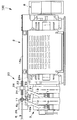
このブレーキ開放装置の構造について図13および図14を参照して概説すると、エレベータ昇降路1の頂部に設けられている巻上機2にはブレーキ3が設けられ、最上階の乗場ホール4の壁面に設けられた操作レバー5から延びる操作ワイヤ6が接続されている。
これにより、停電等によってブレーキが作動したままとなり、乗りかご7を昇降させることができなくなった場合には、救出作業員が操作レバー5を操作してブレーキを手動で開放する。
すると、トラクションシーブ8が回転できる状態となり、乗りかご7と釣合錘9との重量アンバランスによって乗りかご7が自然に上昇しあるいは降下するので、乗りかご7を最寄り階に着床させることができる。
The structure of this brake release device will be outlined with reference to FIGS. 13 and 14. The hoisting
As a result, when the brake remains activated due to a power failure or the like and the car 7 cannot be raised or lowered, the rescue worker operates the operation lever 5 to manually release the brake.
Then, the
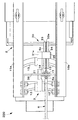
ところで、上述した巻上機2のブレーキ3は、図14に示したように、左右方向に水平に延びる支軸10,11によって前後方向に揺動自在に支持された前後一対のブレーキアーム12,13と、これらのブレーキアームの上端12a,13aが軸支された変位部材14とを有している。
By the way, as shown in FIG. 14, the
また、巻上機2の上部に固定されている左右一対のフレーム15a,15bには、平面視でコ字形のブラケット16が取り付けられ、操作ワイヤ6のアウタチューブ6aの先端が係止具17によって接続されている。
さらに、変位部材14の後端上部14aには、操作ワイヤ6のインナワイヤ6bが図示されない係止具によって接続されている。
これにより、救出運転を行う作業員が操作レバー5を操作してインナワイヤ6bを引き寄せると、変位部材14が矢印Aで示したように前方に変位してブレーキアーム12,13がそれぞれ揺動するので、ブレーキ3を開放することができる。
A pair of left and
Further, the
As a result, when the worker performing the rescue operation operates the operation lever 5 and pulls the
このとき、前後一対のブレーキアーム12,13は、図示されない付勢手段によって常にブレーキ作動側に付勢されているため、ブレーキ3を開放する際には所定の値を上回る操作力で変位部材14を前方に変位させる必要がある。
また、操作ワイヤ6は、最上階の乗場ホールから昇降路の頂部に設けられている巻上機2へと湾曲しながら延びているため、アウタチューブ6aとインナワイヤ6bとの間には互いの摺動に伴う摩擦力が作用する。
これにより、乗りかご7を救出運転する救出作業員は、大きな力で操作レバー5を操作しなければならない。
At this time, since the pair of front and
Further, since the
Thereby, a rescue worker who rescues the car 7 must operate the operation lever 5 with a large force.
さらに、巻上機2が昇降路の頂部に設けられているため、救出作業員が最上階の乗場ホール4からブレーキ3の作動状態を視認することは困難である。
Furthermore, since the hoisting
そこで本発明の目的は、上述した従来技術が有する問題点を解消し、エレベータの巻上機に設けられているブレーキをより小さな操作力で開放できるばかりでなく、ブレーキの作動状態を容易に視認できるように改良されたブレーキ開放装置を提供することにある。 Therefore, the object of the present invention is to solve the above-mentioned problems of the prior art, not only to release the brake provided in the elevator hoisting machine with a smaller operating force, but also to easily visually check the operating state of the brake. It is an object of the present invention to provide an improved brake release device.
上記の課題を解決するための請求項1に記載した手段は、
エレベータ巻上機のブレーキを非常時に操作手段を用いて開放する装置であって、
前記ブレーキを開放するときに変位させる変位部材に支持されて一体に変位する滑車体と、
前記操作手段から延びて前記滑車体の外周部分に巻き付けられた後にその先端が前記巻上機に係止される線状体と、を備え、
前記操作手段を操作して前記線状体を引き寄せると前記滑車体が動滑車として作用し、前記変位手段を変位させて前記ブレーキを開放するように構成されていることを特徴とする。
The means described in
A device for releasing an elevator hoisting machine brake using an operating means in an emergency,
A pulley body that is supported by a displacement member that is displaced when the brake is released, and that is displaced together,
A linear body that extends from the operation means and is wound around the outer peripheral portion of the pulley body, and has its tip locked to the hoisting machine,
When the operation means is operated to draw the linear body, the pulley body acts as a moving pulley, and the displacement means is displaced to release the brake.
すなわち、請求項1に記載したエレベータ巻上機のブレーキ開放装置は、従来のブレーキ開放装置のように線状体によってブレーキの変位部材に直接変位させるのではなく、線状体を滑車体の外周に巻き付けることにより滑車体を「動滑車」として用いて変位部材を変位させる構造である。
これにより、従来のブレーキ開放装置に比較して半分の操作力でブレーキの変位部材を変位させてブレーキを開放することができる。
なお「動滑車」としてのシーブは1つに限られず、例えば2つのシーブを用いて「2重の動滑車」として作用させることもできる。
In other words, the brake hoist release device for an elevator hoist according to
As a result, the brake can be released by displacing the brake displacement member with half the operating force compared to the conventional brake release device.
Note that the sheave as the “moving pulley” is not limited to one. For example, two sheaves can be used to act as a “double moving pulley”.
滑車体は、円形のシーブとし、線状体を最上階の乗場ホールに設けた操作レバーによって操作されるワイヤとすることができる。
また、滑車体をスプロケットとし、線状体をチェーンとすることもできる。
さらには、線状体としてのワイヤあるいはチェーンを、バッテリ駆動の電動アクチュエータによって引き寄せる構造とすることもできる。
加えて、この電動アクチュエータには、エレベータの運行を遠隔監視している監視センターから作動させることができるようにする制御手段を付設することもできる。
The pulley body can be a circular sheave and a wire operated by an operating lever provided with a linear body in the hall on the top floor.
Also, the pulley can be a sprocket and the linear body can be a chain.
Furthermore, it is also possible to adopt a structure in which a wire or chain as a linear body is attracted by a battery-driven electric actuator.
In addition, the electric actuator can be provided with a control means that can be operated from a monitoring center that remotely monitors the operation of the elevator.
滑車体は、変位部材に対し、転がり軸受あるいは滑り軸受を介して回動自在に支持することもできるし、変位部材に回動不能に固定することもできる。
滑車体が変位部材に固定されて回動しないときは、線状体は滑車体の外周上を摺動することになるが、線状体が摺動する部分の表面に摩擦を小さくする手段、例えばポリテトラフルオロエチレンや二硫化モリブデンを含有した低摩擦材料あるいはグリース等を塗布しておくことが好ましい。
また、ポリテトラフルオロエチレン等の低摩擦樹脂材料から成形した薄板を滑車体の外周に貼設しておき、その上を線状体が摺動するように構成することもできる。
The pulley body can be supported rotatably with respect to the displacement member via a rolling bearing or a slide bearing, or can be fixed to the displacement member so as not to rotate.
When the pulley body is fixed to the displacement member and does not rotate, the linear body slides on the outer periphery of the pulley body, but means for reducing friction on the surface of the portion where the linear body slides, For example, it is preferable to apply a low friction material or grease containing polytetrafluoroethylene or molybdenum disulfide.
Alternatively, a thin plate formed from a low friction resin material such as polytetrafluoroethylene may be attached to the outer periphery of the pulley body, and the linear body may slide on the thin plate.
滑車体は、線状体を約半周にわたって巻き付けることができれば良いことから、完全な円形ではなく、半円形状に形成することもできる。
この場合、滑車体を板金材料からプレス加工し、あるいは低摩擦の樹脂材料から射出成形することにより、機械加工によって製作するシーブに比較してその製造コストを低減することができる。
Since the pulley body only needs to be able to wind the linear body over about a half circumference, it can also be formed in a semicircular shape instead of a perfect circle.
In this case, the manufacturing cost can be reduced by pressing the pulley body from a sheet metal material or by injection molding from a low friction resin material as compared with a sheave manufactured by machining.
さらに、滑車体に光線を反射する塗料を塗布し、あるいは自動車若しくは自転車等の後部に取り付けられている光線反射部材や光線反射テープ等の光線反射手段を取り付ければ、懐中電灯のような照明手段を用いることにより、操作手段の側からシーブの前後動、したがってブレーキの開放状態を容易に視認することができる。 Furthermore, if a light reflecting material such as a light reflecting member or a light reflecting tape attached to the rear part of an automobile or a bicycle is applied to the sliding body, a lighting device such as a flashlight is provided. By using it, the forward and backward movement of the sheave, that is, the released state of the brake can be easily visually recognized from the operation means side.
さらに、滑車体の周囲をカバー部材で覆うことにより、巻上機やブレーキ開放装置の点検作業を行う作業員が滑車体に不用意に触れてブレーキが開放されてしまうことを防止できるとともに、塵芥等が付着して作動不良となることを防止できる。
このとき、カバー部材を透明な材料から構成すれば、最上階の乗場ホールから滑車体の回動状態、したがってブレーキの開放状態を容易に視認することができる。
Furthermore, by covering the periphery of the pulley body with a cover member, it is possible to prevent an operator who inspects the hoisting machine and the brake release device from inadvertently touching the pulley body and releasing the brake, It is possible to prevent malfunction due to adhesion of the like.
At this time, if the cover member is made of a transparent material, the rotating state of the pulley body, and hence the brake released state, can be easily visually recognized from the hall on the top floor.
加えて、滑車体には、ブレーキの変位部材を変位させない所定の揺動位置へと滑車体を復帰させるための付勢手段を設けることができる。
これにより、操作ワイヤのアウタチューブとインナワイヤとの間の摺動摩擦によってインナワイヤが戻らなくなり、ブレーキの変位部材が変位したままとなってブレーキが開放されたままとなることを確実に防止することができる。
In addition, the pulley body can be provided with urging means for returning the pulley body body to a predetermined swing position where the displacement member of the brake is not displaced.
This prevents the inner wire from returning due to the sliding friction between the outer tube of the operation wire and the inner wire, and can reliably prevent the brake from being released due to the displacement member of the brake being left displaced. .
本発明によれば、エレベータの巻上機に設けられているブレーキをより小さな操作力で開放することができるばかりでなく、ブレーキの作動状態を容易に視認できるように改良されたブレーキ開放装置を提供することができる。 According to the present invention, there is provided an improved brake release device that not only can release a brake provided in an elevator hoisting machine with a smaller operating force but also can easily recognize the operating state of the brake. Can be provided.
以下、図1乃至図12を参照し、本発明のエレベータ巻上機のブレーキ開放装置およびそれを備えたエレベータシステムの各実施形態および各変形例について詳細に説明する。 なお、以下の説明においては、前述した従来の装置を含めて同一の部分には同一の符号を用いて重複した説明を省略する。 Hereinafter, with reference to FIG. 1 thru | or FIG. 12, each embodiment and each modification of the brake releasing apparatus of the elevator hoisting machine of this invention and an elevator system provided with the same are demonstrated in detail. In the following description, the same reference numerals are used for the same parts including the above-described conventional apparatus, and a duplicate description is omitted.
第1実施形態
まず最初に図1〜図3を参照し、第1実施形態のブレーキ開放装置およびそれを備えたエレベータシステムについて説明する。
1st Embodiment First, with reference to FIGS. 1-3, the brake release apparatus of 1st Embodiment and an elevator system provided with the same are demonstrated.
第1実施形態のエレベータシステム100は、図13に示した従来技術と同様に、エレベータ昇降路1の頂部に配設された巻上機2を備えている。
巻上機2にはブレーキ3が設けられ、トラクションシーブ8を回転不能に制動できるようになっている。
そして、このブレーキ3には、最上階の乗場ホール4の壁面に設けられた操作レバー5から延びる操作ワイヤ6が、図1〜図3に示したブレーキ開放装置20を介して接続されている。
The
The hoisting
And the
ブレーキ開放装置20は、図1〜図3に示したように、ブレーキ3の前後一対のブレーキアーム12,13の上端がそれぞれ軸支されている変位部材21を有しており、図3中に矢印Cで示したように、この変位部材21を前方に変位させるとブレーキ3が開放されてトラクションシーブ8が回動できる状態となる。
この変位部材21の後端には上方に延びる支軸22が突設され、シーブ23を鉛直方向に延びる回動軸線の回りに回動自在に支持している。
As shown in FIGS. 1 to 3, the
A
また、支軸22には断面形状コ字形のブラケット24が取り付けられてシーブ23を左右方向に囲んでおり、操作ワイヤ6のインナワイヤ6bがシーブ23の外周溝23aから脱落することを防止している。
さらに、ブラケット24のうち、最上階の乗場ホール4から視認できる側の端部には光線反射体25が垂設されている。
Further, a
Further, a
さらに、巻上機2の左右一対のフレーム15a,15bの前端部分に掛け渡された平面視でコ字形のブラケット26の右端側には、操作ワイヤ6のアウタチューブ6aの前端が係止具17によって係止されている。
また、このブラケット26の左端側には、シーブ23に半周巻き付けられてU字状に延びる操作ワイヤ6のインナワイヤ6bの前端が係止具18によって係止されている。
Further, the front end of the
Further, on the left end side of the
これにより、最上階の乗場ホール4の壁面に設けられている操作レバー5を操作して、図3中に矢印Bで示したようにインナワイヤ6bを前方に引き寄せると、シーブ23が「動滑車」として作用して矢印Cで示したように変位部材21を前方に変位させる。
すると、前後一対のブレーキアーム12,13が支軸10,11の回りに揺動するので、巻上機2のブレーキ3が開放されトラクションシーブ8が回転できるようになる。
Accordingly, when the operation lever 5 provided on the wall surface of the
Then, the pair of front and
このとき、シーブ23が変位部材21を前方に変位させる力の大きさは、操作レバー5によってインナワイヤ6bを前方に変位させる力の2倍となる。
したがって、図13に示した従来のブレーキ開放装置に比較すると、ブレーキ3を開放するために操作レバー5に加える操作力の大きさは2分の1で済むことになる。
At this time, the magnitude of the force that the
Therefore, compared with the conventional brake releasing device shown in FIG. 13, the magnitude of the operating force applied to the operating lever 5 to release the
さらに、図1に示したように、シーブ23を左右方向に取り囲んでいるブラケット24の端部には光線反射体25が取り付けられている。
これにより、最上階の乗場ホール4において操作レバー5を操作する作業員が、巻上機2に向かって照明の光を照射すると、シーブ23の前後動、したがってブレーキ3の作動状態を容易に視認することができる。
Further, as shown in FIG. 1, a
As a result, when an operator operating the operation lever 5 in the
第2実施形態
次に図4および図5を参照し、第2実施形態のブレーキ開放装置30およびそれを備えたエレベータシステム110について説明する。
2nd Embodiment Next, with reference to FIG. 4 and FIG. 5, the
上述した第1実施形態のブレーキ開放装置20においては、鉛直方向に延びる軸線の回りにシーブが回動する構造であったが、本第2実施形態のブレーキ開放装置30においては、左右方向に水平に延びる軸線の回りにシーブが回動する構造となっている。
In the
具体的に説明すると、このブレーキ開放装置30は、ブレーキ3の前後一対のブレーキアーム12,13の上端がそれぞれ軸支されている変位部材31を有している。
この変位部材31の後端には上方に延びる支持部31aが突設されているとともに、この支持部31aの上端には右方に水平に延びる支軸32が取り付けられて、シーブ33を左右方向に水平に延びる軸線の回りに回動自在に支持している。
More specifically, the
A
また、支軸32には断面形状コ字形のブラケット34が取り付けられてシーブ33を上下方向に囲んでおり、操作ワイヤ6のインナワイヤ6bがシーブ33の外周溝33aから脱落することを防止している。
さらに、ブラケット34のうち、上端側には光線反射体35が貼設されている。
Further, a
Furthermore, a
さらに、巻上機2の左右一対のフレーム15a,15bの前端部分に掛け渡された平面視でコ字形のブラケット26の下端には、操作ワイヤ6のアウタチューブ6aの前端が係止具17によって係止されている。
また、このブラケット26の上端には、シーブ33に半周巻き付けられてU字状に延びる操作ワイヤ6のインナワイヤ6bの前端が係止具18によって係止されている。
Further, the front end of the
In addition, the front end of the
これにより、最上階の乗場ホール4の壁面に設けられている操作レバー5を操作して、図4中に矢印Bで示したようにインナワイヤ6bを前方に引き寄せると、シーブ23が「動滑車」として作用して矢印Cで示したように変位部材31を前方に変位させる。
すると、前後一対のブレーキアーム12,13が支軸10,11の回りに揺動するので、巻上機2のブレーキ3が開放されトラクションシーブ8が回転できるようになる。
As a result, when the operation lever 5 provided on the wall surface of the
Then, the pair of front and
このとき、シーブ33が変位部材31を前方に変位させる力の大きさは、操作レバー5によってインナワイヤ6bを前方に変位させる力の2倍となる。
したがって、図13に示した従来のブレーキ開放装置に比較すると、ブレーキ3を開放するために操作レバー5に加える操作力の大きさは2分の1で済むことになる。
At this time, the magnitude of the force that the
Therefore, compared with the conventional brake releasing device shown in FIG. 13, the magnitude of the operating force applied to the operating lever 5 to release the
さらに、図4に示したように、シーブ33を上下方向に取り囲んでいるブラケット34の上端部には光線反射体35が取り付けられている。
これにより、最上階の乗場ホール4において操作レバー5を操作する作業員が、巻上機2に向かって照明の光を照射すると、シーブ33の前後動、したがってブレーキ3の作動状態を容易に視認することができる。
Further, as shown in FIG. 4, a
As a result, when an operator operating the operating lever 5 in the
第1変形例
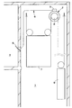
次に図6を参照し、上述した第1実施形態のブレーキ開放装置20の変形例について説明する。
First Modification Next, with reference to FIG. 6, a modification of the
この第1変形例のブレーキ開放装置40は、図3に示した第1実施形態のブレーキ開放装置20に対し、変位部材21を変位させない所定の位置へとシーブ23を復帰させるための付勢手段を追加したものとなっている。
具体的に説明すると、巻上機2の上部に固定されたブラケット41には、前後方向に延びる引張りコイルばね42が取り付けられている。
そして、この引張りコイルばね42の前端は、シーブ23を回動自在に支持している支軸22の上端に接続されている。
The
More specifically, a
The front end of the
これにより、シーブ23は、引張りコイルばね42によって常に付勢されて後方に変位しようとし、操作ワイヤ6のインナワイヤ6bを後方に引き寄せる。
したがって、操作ワイヤ6のアウタチューブ6aとインナワイヤ6bとの間の摺動摩擦によってインナワイヤ6bが前方に引き寄せられたまま戻らなくなり、変位部材21が前方に変位したままとなってブレーキ2が開放されたままとなることを確実に防止することができる。
As a result, the
Therefore, the
第2変形例
次に図7を参照し、上述した第2実施形態のブレーキ開放装置30の変形例について説明する。
Second Modified Example Next, a modified example of the
図7に示した第2変形例のブレーキ開放装置50は、図4に示した第2実施形態のブレーキ開放装置30の全体を透明なカバー部材51で覆った構造となっている。
これにより、巻上機2の点検作業を行う作業員がシーブ33等に不用意に触れてブレーキ3を開放してしまうことを防止できるとともに、シーブ33等に塵芥が付着して作動不良となることを確実に防止することができる。
また、透明なカバー部材51を介して、ブラケット34の上端に取り付けられている光線反射体35を視認することができるから、最上階の乗場ホール4からブラケット34、したがってブレーキ3の状態を容易に視認することができる。
The
As a result, it is possible to prevent an operator who inspects the hoisting
Further, since the
第3実施形態
次に図8を参照し、第3実施形態のブレーキ開放装置60およびそれを備えたエレベータシステム300について説明する。
3rd Embodiment Next, with reference to FIG. 8, the
上述した第1実施形態のブレーキ開放装置20は、変位部材21に設けた単一のシーブ23にインナワイヤ6bを2:1タイプの引き回しで巻き付けた構造であった。
これに対して、本第3実施形態のブレーキ開放装置は、変位部材に設けた左右一対の可動シーブにインナワイヤ6bを4:1タイプの引き回しで巻き付けた構造となっている。
The
In contrast, the brake release device of the third embodiment has a structure in which the
具体的に説明すると、変位部材61に固定されたブラケット62によって左右一対の可動シーブ63,64がそれぞれ回動自在に支持されている。
また、平面視でコ字形のブラケット26に固定されたブラケット65には、固定シーブ66が回動自在に支持されている。
そして、操作ワイヤ6のインナワイヤ6bは、右側の可動シーブ63から固定シーブ66,左側の可動シーブ64の順に巻き付けられて、その先端が係止具18によってブラケット26に係止されている。
More specifically, a pair of left and right
A fixed
The
これにより、最上階の乗場ホール4の壁面に設けられている操作レバー5を操作して、図8中に矢印Bで示したようにインナワイヤ6bを前方に引き寄せると、左右一対の可動シーブ63,64が「2重の動滑車」として作用して矢印Cで示したように変位部材61を前方に変位させる。
すると、前後一対のブレーキアーム12,13が支軸10,11の回りに揺動するので、巻上機2のブレーキ3が開放されトラクションシーブ8が回転できるようになる。
As a result, when the operation lever 5 provided on the wall surface of the
Then, the pair of front and
このとき、左右一対の可動シーブ63,64が変位部材61を前方に変位させる力の大きさは、操作レバー5によってインナワイヤ6bを前方に変位させる力の4倍となる。
したがって、図14に示した従来のブレーキ開放装置に比較すると、ブレーキ3を開放するために操作レバー5に加える操作力の大きさは4分の1で済むことになる。
At this time, the magnitude of the force that causes the pair of left and right
Therefore, as compared with the conventional brake release device shown in FIG. 14, the magnitude of the operation force applied to the operation lever 5 to release the
第3変形例
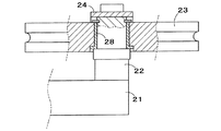
次に図9〜図12を参照し、第1実施形態のブレーキ開放装置20におけるシーブ支持構造と、その変形例について説明する。
Third Modification Next, a sheave support structure in the
図9に示したように、第1実施形態のブレーキ開放装置20におけるシーブ23は、支軸22に対し玉軸受27を介して回動自在に取り付けられている。
これに対して、図10に示した変形例では、シーブ23が支軸22に対し滑り軸受28を介して回動自在に支持されている。
なお、この滑り軸受は、例えば潤滑油を含浸させた樹脂製の円筒部材、あるいは二硫化モリブデン等の固体潤滑剤を含浸させた金属製の円筒部材とすることができる。
As shown in FIG. 9, the
On the other hand, in the modification shown in FIG. 10, the
The sliding bearing may be a resin cylindrical member impregnated with, for example, a lubricating oil or a metallic cylindrical member impregnated with a solid lubricant such as molybdenum disulfide.
さらに、図11に示した変形例では、シーブ23が支軸22に嵌着されて回動不能となっている。
そのため、操作ワイヤ6のインナワイヤ6bは、シーブ23の溝23aの表面上を摺動するが、外周溝23aの表面に二硫化モリブデンを含有するグリースが塗布されているため、インナワイヤ6bの作動を妨げることはない。
Furthermore, in the modified example shown in FIG. 11, the
Therefore, the
加えて、図12に示した変形例では、略半円形に形成されたシーブ71が支軸22に嵌着されて回動不能となっている。
このとき、シーブ71は、例えば板金材料からプレス加工し、あるいは低摩擦の樹脂材料から射出成形することにより、機械加工によって製作するシーブに比較してその製造コストを低減することができる。
また、板金製のシーブ71の溝部71aにポリテトラフルオロエチレン等の低摩擦性の樹脂材料の薄板を貼設することにより、インナワイヤ6bがその上を滑らかに摺動するように構成することもできる。
In addition, in the modification shown in FIG. 12, the
At this time, the manufacturing cost of the
Further, by attaching a thin plate of a low-friction resin material such as polytetrafluoroethylene to the
以上、本発明に係るエレベータ巻上機のブレーキ開放装置およびそれを備えたエレベータシステムの各実施形態および各変形例について詳しく説明したが、本発明は上述した実施形態によって限定されるものではなく、種々の変更が可能である。
例えば、図1および図2に示したブレーキ開放装置20,30においては、シーブ23,33を取り囲むブラケット24,34に光線反射体25,35を取り付けていた。
これに対し、シーブ23,33そのものに光線反射体25,35を直接取り付けることもできる。
As mentioned above, although each embodiment and each modification of a brake release device of an elevator hoisting machine concerning the present invention and an elevator system provided with it were explained in detail, the present invention is not limited by the embodiment mentioned above, Various changes are possible.
For example, in the
On the other hand, the
1 エレベータの昇降路
2 巻上機
3 ブレーキ
4 乗場ホール
5 操作レバー
6 操作ワイヤ
7 乗りかご
8 トラクションシーブ
9 釣合錘
10,11 ブレーキの支軸
12,13 ブレーキアーム
14 変位部材
15a,15b フレーム
16 ブラケット
20 第1実施形態のブレーキ開放装置
21 変位部材
22 支軸
23 シーブ
24 ブラケット
25 光線反射体
27 玉軸受
28 滑り軸受
30 第2実施形態のブレーキ開放装置
31 変位部材
32 支軸
33 シーブ
34 ブラケット
35 光線反射体
40 第1変形例のブレーキ開放装置
41 ブラケット
42 引張りコイルばね
50 第2変形例のブレーキ開放装置
51 カバー部材
60 第3実施形態のブレーキ開放装置
61 変位部材
62 ブラケット
63,64 可動シーブ
65 ブラケット
66 固定シーブ
65 コイルばね(付勢手段)
71 シーブ
100 第1実施形態のブレーキ開放装置を備えたエレベータシステム
110 第1変形例のブレーキ開放装置を備えたエレベータシステム
200 第2実施形態のブレーキ開放装置を備えたエレベータシステム
210 第2変形例のブレーキ開放装置を備えたエレベータシステム
300 第3実施形態のブレーキ開放装置を備えたエレベータシステム
DESCRIPTION OF
71
Claims (12)
前記ブレーキを開放するときに変位させる変位部材に支持されて一体に変位する滑車体と、
前記操作手段から延びて前記滑車体の外周部分に巻き付けられた後にその先端が前記巻上機に係止される線状体と、を備え、
前記操作手段を操作して前記線状体を引き寄せると前記滑車体が動滑車として作用し、前記変位手段を変位させて前記ブレーキを開放するように構成されていることを特徴とするエレベータ巻上機のブレーキ開放装置。 A device for releasing an elevator hoisting machine brake using an operating means in an emergency,
A pulley body that is supported by a displacement member that is displaced when the brake is released, and that is displaced together,
A linear body that extends from the operation means and is wound around the outer peripheral portion of the pulley body, and has its tip locked to the hoisting machine,
The elevator hoisting machine is configured so that when the linear member is pulled by operating the operating means, the pulley body acts as a moving pulley, and the displacement means is displaced to release the brake. Machine brake release device.
Priority Applications (3)
| Application Number | Priority Date | Filing Date | Title |
|---|---|---|---|
| JP2007227767A JP5288366B2 (en) | 2007-09-03 | 2007-09-03 | Brake release device for elevator hoisting machine and elevator system including the same |
| MYPI20083300 MY150283A (en) | 2007-09-03 | 2008-08-27 | Brake releasing mechanism for elevator hoist and elevator system provided with the same |
| CN2008102133835A CN101381049B (en) | 2007-09-03 | 2008-09-02 | Brake release mechanism for elevator lifting device and elevator system with thereof |
Applications Claiming Priority (1)
| Application Number | Priority Date | Filing Date | Title |
|---|---|---|---|
| JP2007227767A JP5288366B2 (en) | 2007-09-03 | 2007-09-03 | Brake release device for elevator hoisting machine and elevator system including the same |
Publications (2)
| Publication Number | Publication Date |
|---|---|
| JP2009057189A true JP2009057189A (en) | 2009-03-19 |
| JP5288366B2 JP5288366B2 (en) | 2013-09-11 |
Family
ID=40461143
Family Applications (1)
| Application Number | Title | Priority Date | Filing Date |
|---|---|---|---|
| JP2007227767A Expired - Fee Related JP5288366B2 (en) | 2007-09-03 | 2007-09-03 | Brake release device for elevator hoisting machine and elevator system including the same |
Country Status (3)
| Country | Link |
|---|---|
| JP (1) | JP5288366B2 (en) |
| CN (1) | CN101381049B (en) |
| MY (1) | MY150283A (en) |
Cited By (2)
| Publication number | Priority date | Publication date | Assignee | Title |
|---|---|---|---|---|
| CN111320048A (en) * | 2020-03-13 | 2020-06-23 | 深圳市特种设备安全检验研究院 | Elevator brake testing device and testing method thereof |
| CN111320048B (en) * | 2020-03-13 | 2024-06-04 | 深圳市质量安全检验检测研究院 | Elevator brake test device and test method thereof |
Families Citing this family (1)
| Publication number | Priority date | Publication date | Assignee | Title |
|---|---|---|---|---|
| WO2022003756A1 (en) | 2020-06-29 | 2022-01-06 | 三菱電機株式会社 | Control device, apparatus system, apparatus control method, and program |
Citations (13)
| Publication number | Priority date | Publication date | Assignee | Title |
|---|---|---|---|---|
| JPH01236188A (en) * | 1988-03-14 | 1989-09-21 | Mitsubishi Electric Corp | Elevator |
| JPH0361282A (en) * | 1989-07-31 | 1991-03-18 | Mitsubishi Electric Corp | Brake device for elevator winding machine |
| JPH03205292A (en) * | 1990-01-08 | 1991-09-06 | Hitachi Ltd | Device for illuminating companion way for passenger conveyor |
| JPH0527066U (en) * | 1991-09-20 | 1993-04-06 | 村田機械株式会社 | Jacquard threading suspension device |
| JPH0755670B2 (en) * | 1989-08-21 | 1995-06-14 | ブリヂストンサイクル株式会社 | Brake device for bicycle |
| JPH0727255Y2 (en) * | 1989-04-13 | 1995-06-21 | 株式会社丸山製作所 | Brake device for vehicle |
| JP2001224113A (en) * | 2000-02-08 | 2001-08-17 | Kawasaki Heavy Ind Ltd | Apparatus and method for inserting linear member |
| JP2003104642A (en) * | 2001-09-28 | 2003-04-09 | Toshiba Elevator Co Ltd | Elevator device and method for releasing brake thereof |
| JP2003276959A (en) * | 2002-03-26 | 2003-10-02 | Kitakyushu City | Elevator automatic operation system for handicapped person |
| JP2005320143A (en) * | 2004-05-11 | 2005-11-17 | Mitsubishi Electric Building Techno Service Co Ltd | Rescue device for confined passengers in elevator |
| JP2006007930A (en) * | 2004-06-24 | 2006-01-12 | Honda Motor Co Ltd | Parking brake device |
| WO2007020705A1 (en) * | 2005-08-19 | 2007-02-22 | Mitsubishi Denki Kabushiki Kaisha | Deflection sheave device |
| JP2007536185A (en) * | 2004-05-04 | 2007-12-13 | オロナ エス コープ | Emergency device for raising and lowering an elevator that has stopped moving between floors |
Family Cites Families (2)
| Publication number | Priority date | Publication date | Assignee | Title |
|---|---|---|---|---|
| JPH078710B2 (en) * | 1992-11-17 | 1995-02-01 | 善廣 西山 | Unpowered emergency elevator |
| JP4052304B2 (en) * | 2004-11-09 | 2008-02-27 | 株式会社日立製作所 | Elevator |
-
2007
- 2007-09-03 JP JP2007227767A patent/JP5288366B2/en not_active Expired - Fee Related
-
2008
- 2008-08-27 MY MYPI20083300 patent/MY150283A/en unknown
- 2008-09-02 CN CN2008102133835A patent/CN101381049B/en active Active
Patent Citations (13)
| Publication number | Priority date | Publication date | Assignee | Title |
|---|---|---|---|---|
| JPH01236188A (en) * | 1988-03-14 | 1989-09-21 | Mitsubishi Electric Corp | Elevator |
| JPH0727255Y2 (en) * | 1989-04-13 | 1995-06-21 | 株式会社丸山製作所 | Brake device for vehicle |
| JPH0361282A (en) * | 1989-07-31 | 1991-03-18 | Mitsubishi Electric Corp | Brake device for elevator winding machine |
| JPH0755670B2 (en) * | 1989-08-21 | 1995-06-14 | ブリヂストンサイクル株式会社 | Brake device for bicycle |
| JPH03205292A (en) * | 1990-01-08 | 1991-09-06 | Hitachi Ltd | Device for illuminating companion way for passenger conveyor |
| JPH0527066U (en) * | 1991-09-20 | 1993-04-06 | 村田機械株式会社 | Jacquard threading suspension device |
| JP2001224113A (en) * | 2000-02-08 | 2001-08-17 | Kawasaki Heavy Ind Ltd | Apparatus and method for inserting linear member |
| JP2003104642A (en) * | 2001-09-28 | 2003-04-09 | Toshiba Elevator Co Ltd | Elevator device and method for releasing brake thereof |
| JP2003276959A (en) * | 2002-03-26 | 2003-10-02 | Kitakyushu City | Elevator automatic operation system for handicapped person |
| JP2007536185A (en) * | 2004-05-04 | 2007-12-13 | オロナ エス コープ | Emergency device for raising and lowering an elevator that has stopped moving between floors |
| JP2005320143A (en) * | 2004-05-11 | 2005-11-17 | Mitsubishi Electric Building Techno Service Co Ltd | Rescue device for confined passengers in elevator |
| JP2006007930A (en) * | 2004-06-24 | 2006-01-12 | Honda Motor Co Ltd | Parking brake device |
| WO2007020705A1 (en) * | 2005-08-19 | 2007-02-22 | Mitsubishi Denki Kabushiki Kaisha | Deflection sheave device |
Cited By (2)
| Publication number | Priority date | Publication date | Assignee | Title |
|---|---|---|---|---|
| CN111320048A (en) * | 2020-03-13 | 2020-06-23 | 深圳市特种设备安全检验研究院 | Elevator brake testing device and testing method thereof |
| CN111320048B (en) * | 2020-03-13 | 2024-06-04 | 深圳市质量安全检验检测研究院 | Elevator brake test device and test method thereof |
Also Published As
| Publication number | Publication date |
|---|---|
| JP5288366B2 (en) | 2013-09-11 |
| CN101381049B (en) | 2011-04-13 |
| CN101381049A (en) | 2009-03-11 |
| MY150283A (en) | 2013-12-31 |
Similar Documents
| Publication | Publication Date | Title |
|---|---|---|
| JP4905360B2 (en) | Elevator governor | |
| JP4722855B2 (en) | Elevator equipment | |
| JP5287859B2 (en) | Elevator governor | |
| JP2009196793A (en) | Emergency braking device for passenger conveyer | |
| EP2810911A1 (en) | A drive machine for an elevator and an elevator | |
| JPWO2011004468A1 (en) | Elevator direct-acting drum brake device | |
| JPWO2006018884A1 (en) | Elevator brake equipment | |
| JP5288366B2 (en) | Brake release device for elevator hoisting machine and elevator system including the same | |
| JP5341400B2 (en) | Manual lowering device in case of power failure of elevator | |
| JP4558724B2 (en) | Elevator hoisting machine and brake device therefor | |
| JP5163455B2 (en) | Elevator passenger rescue device | |
| JP2004137037A (en) | Lifting driving device for elevator | |
| JP6525363B2 (en) | Elevator braking system | |
| JP4677409B2 (en) | Elevator equipment | |
| WO2006064554A1 (en) | Hoist for elevator | |
| JP5914320B2 (en) | Stair lift safety device | |
| JP2004142914A (en) | Emergency stop device of elevator | |
| JP6231248B1 (en) | Brake device for elevator rope replacement support | |
| JP5327828B2 (en) | Brake release device for elevator hoisting machine and elevator system including the same | |
| JP5709679B2 (en) | Human-powered drive system for elevator hoist | |
| JP6289259B2 (en) | Escalator emergency braking device and escalator | |
| JP4316995B2 (en) | Passenger conveyor and braking method thereof | |
| JP2010173776A (en) | Damping force setting device of elevator hoist | |
| JPWO2018011960A1 (en) | Passenger conveyor safety device | |
| JP4266468B2 (en) | Gold wheel with sensor |
Legal Events
| Date | Code | Title | Description |
|---|---|---|---|
| A621 | Written request for application examination |
Free format text: JAPANESE INTERMEDIATE CODE: A621 Effective date: 20100317 |
|
| A977 | Report on retrieval |
Free format text: JAPANESE INTERMEDIATE CODE: A971007 Effective date: 20120523 |
|
| A131 | Notification of reasons for refusal |
Free format text: JAPANESE INTERMEDIATE CODE: A131 Effective date: 20120529 |
|
| A521 | Written amendment |
Free format text: JAPANESE INTERMEDIATE CODE: A523 Effective date: 20120723 |
|
| A131 | Notification of reasons for refusal |
Free format text: JAPANESE INTERMEDIATE CODE: A131 Effective date: 20130111 |
|
| A521 | Written amendment |
Free format text: JAPANESE INTERMEDIATE CODE: A523 Effective date: 20130305 |
|
| A01 | Written decision to grant a patent or to grant a registration (utility model) |
Free format text: JAPANESE INTERMEDIATE CODE: A01 Effective date: 20130507 |
|
| A61 | First payment of annual fees (during grant procedure) |
Free format text: JAPANESE INTERMEDIATE CODE: A61 Effective date: 20130528 |
|
| S531 | Written request for registration of change of domicile |
Free format text: JAPANESE INTERMEDIATE CODE: R313531 |
|
| R350 | Written notification of registration of transfer |
Free format text: JAPANESE INTERMEDIATE CODE: R350 |
|
| LAPS | Cancellation because of no payment of annual fees |