JP2009024435A - Wall frame structure reinforced in terms of vibration control performance - Google Patents
Wall frame structure reinforced in terms of vibration control performance Download PDFInfo
- Publication number
- JP2009024435A JP2009024435A JP2007190365A JP2007190365A JP2009024435A JP 2009024435 A JP2009024435 A JP 2009024435A JP 2007190365 A JP2007190365 A JP 2007190365A JP 2007190365 A JP2007190365 A JP 2007190365A JP 2009024435 A JP2009024435 A JP 2009024435A
- Authority
- JP
- Japan
- Prior art keywords
- wall frame
- hardware
- transmission plate
- wall
- damper
- Prior art date
- Legal status (The legal status is an assumption and is not a legal conclusion. Google has not performed a legal analysis and makes no representation as to the accuracy of the status listed.)
- Pending
Links
Images


Abstract
Description
本発明は、木造住宅における壁フレームの制振補強構造に関する。 The present invention relates to a vibration damping reinforcement structure for a wall frame in a wooden house.
木造住宅の地震対策としてダンパーを利用する制振装置を用いた制振補強構造は、強い振動を減衰させて住宅が受ける脆性破壊的な危険を解決するものとして注目されている。制振補強構造は、地震による強い振動を壁フレーム(木造住宅における左右の柱と土台及び梁とがなす構造)を通じて制振装置のダンパーに伝達させ、ダンパー機能(油などの流通抵抗、粘弾性、ばねなどの弾性、摩擦抵抗など)により減衰させることを原理としている。 Damping and reinforcing structures using damping devices that use dampers as countermeasures against earthquakes in wooden houses are attracting attention as a means to dampen strong vibrations and solve the brittle and destructive danger that houses receive. The vibration damping reinforcement structure transmits strong vibrations caused by earthquakes to the damper of the vibration damping device through the wall frame (structure made by the left and right pillars and foundations and beams in a wooden house), and the damper function (distribution resistance such as oil, viscoelasticity) It is based on the principle of damping by the elasticity of springs, friction resistance, etc.).
特許文献1の制振装置では、左右の柱(柱材A,B)の柱脚、柱頭と土台及び梁(横架材C,D)とをほぞで結合すると共にL字状の接合具Eで引抜き補強した壁フレームにおいて、一方の柱材Aと一方の横架材Cとに粘弾性材を減衰材としたダンパー体2を架け渡した構造としている。この構造では、柱材Aが撓んだり湾曲変形しやすいので、柱材Aに剛性補強材3を用いている。
In the vibration damping device of
特許文献2の制振装置では、前記と同様構造の壁フレームにおいて、一方の柱材Aにダンパー体2を取り付け、他方の柱材Bの2箇所とダンパー体2とを2本のブレース材3で結合した構造としている。この構造では、柱材Aが撓んだり湾曲したりするので、柱材Aに剛性補強材4を取り付けている。
In the vibration damping device of
特許文献3の制振構造における制振装置は、壁フレームの下部に配置した油圧ダンパー21と左右の柱における柱脚、柱頭部に一端を取り付けた筋交いのような2本の伝達部材13,14の他端を油圧ダンパー12へ結合する構造において、上下の梁3,4に対してほぼ平行にガイドレール17を左右の柱1,2に横架して固設し、ガイドレール17へ摺動可能に取り付けたガイド15に前記伝達部材の他端を結合し、前記2本の伝達部材13,14の他端をガイド部材と一体に移動させる構造である。これにより、壁フレームが変形するときに伝達部材を含むダンパー取付け部材がねじれてしまうのをガイドレールで防止するものである。
The vibration damping device in the vibration damping structure of
種々提案されている制振補強構造における制振装置は、理論上充分な制振機能を発揮する。一方、実際の木造住宅やその施工では、制振機能に優れることはもちろん地震の振動に対して壁フレームが安定した構造であること、施工しやすく安価に施工できるものであることなどが要求される。 Various proposed damping devices for damping and reinforcing structures exhibit a theoretically sufficient damping function. On the other hand, in actual wooden houses and their construction, it is required that the wall frame has a stable structure against earthquake vibration as well as being excellent in damping function, and that it can be constructed easily and inexpensively. The
この発明は、制振装置を構造が簡素で、安価であり、かつ、施工しやすいものとし、さらに、制振性能の高い、制振補強された壁フレーム構造の提供を課題とする。 It is an object of the present invention to provide a wall frame structure with a damping structure that has a simple structure, is inexpensive, is easy to construct, and has a high damping performance.
木造住宅における左右の柱と上下の横架材(例えば、土台及び梁)とで形成された壁フレームにおいて、左右の柱間を伝達板とダンパーで結合する制振装置において、伝達板は構造用合板やチップ圧縮板材、集成材板などの木材板から切り出した長方形とし、これらを左右の柱にそれぞれ長方形の長辺で固定し、ついで、左右の伝達板間をダンパーで結合する。
柱と伝達板との固定に長尺の連結金物を用いることがある。連結金物は、取付け壁と側壁とを一体に備え、左右の柱の対向面に取付け壁で固定し、側壁に伝達板の長辺を固定する。
In a vibration control device that connects the left and right columns with a transmission plate and a damper in a wall frame formed of left and right columns and upper and lower horizontal members (for example, foundations and beams) in a wooden house, the transmission plate is for structural use. Rectangles cut from wood boards such as plywood, chip compression board, and laminated board are fixed to the left and right pillars with long sides of the rectangle, and then the left and right transmission plates are connected with dampers.
A long connecting hardware may be used to fix the column and the transmission plate. The connecting hardware integrally includes a mounting wall and a side wall, and is fixed to the opposing surfaces of the left and right columns by the mounting wall, and the long side of the transmission plate is fixed to the side wall.
壁フレームに作用する地震の振動をダンパーに伝える伝達板を、木材板を長方形に切出したものとしているので、梁成(取り付けた梁の上下方向寸法)など現場の状況に応じて一部を切除するなどのことにより伝達用板の長辺寸法、短辺寸法を簡単に調整することができ、制振装置を壁フレームの現状に応じた寸法としやすい。伝達板が金属製の場合、現場における寸法調整が困難である。また、取り付けに際してねじの位置が多少ずれても木材であれば対応しやすいが、金属板ではボルト孔が柱側の取付け位置とに狂いがあると、現場では調整ができず、取り扱いにくい。
伝達板として、壁フレームの変形に対して座屈しない程度の厚さと硬さを備えたものを選択し、かつ、長方形で二次断面係数の高いものとできるので、伝達板が地震力で変形することが無い。また、柱は伝達板の長辺が固定されることにより、撓むのが防止されるので地震力を効率よくダンパーに伝達することができる。
The transmission plate that transmits the vibration of the earthquake acting on the wall frame to the damper is cut out in a rectangular shape, so a part of the plate is cut out according to the situation at the site, such as beam formation (vertical dimension of the installed beam) By doing so, it is possible to easily adjust the long side dimension and the short side dimension of the transmission plate, and the vibration damping device can be easily sized according to the current state of the wall frame. When the transmission plate is made of metal, it is difficult to adjust the dimensions on site. Moreover, even if the screw position is slightly shifted during installation, it is easy to cope with wood, but if the bolt hole is misaligned with the mounting position on the pillar side in the metal plate, it cannot be adjusted on site and difficult to handle.
As the transmission plate, one with thickness and hardness that does not buckle against deformation of the wall frame can be selected, and it can be rectangular and have a high secondary section modulus, so the transmission plate is deformed by seismic force There is nothing to do. Moreover, since the pillar is prevented from bending by fixing the long side of the transmission plate, the seismic force can be efficiently transmitted to the damper.
制振装置としての部品点数が少なく、部品間の結合にすべりを生じる機会が少ない。このため、地震力を効率よくダンパーに伝達することができる。
施工が簡単で、制振補強を軸組み段階での作業員が施工できる。
この制振装置は、床と天井間に納まる寸法にもできるので、床と天井を壊すことなく、内壁材だけを除去して、室内側から施工できる。従って、新築はもちろん既存住宅の地震対策として安価に施工できる。
The number of parts as a vibration control device is small, and there is little chance of slipping in the coupling between parts. For this reason, seismic force can be efficiently transmitted to the damper.
Construction is easy, and workers at the shaft assembly stage can perform vibration damping reinforcement.
Since this vibration damping device can be sized to fit between the floor and the ceiling, it can be constructed from the indoor side by removing only the inner wall material without breaking the floor and the ceiling. Therefore, it can be constructed at low cost as an earthquake countermeasure for existing houses as well as new buildings.
連結金物を利用するときは、連結金物を柱の対向面へ固定すると共にこの金物に伝達板を固定するので、柱に伝達板を固定するに際して、補助桟を左右柱のそれぞれの柱の対向面に取り付けるなどの現場作業を省くことができる。また、工場生産の金物を用いて伝達板を固定するので伝達板と柱との固定状態が安定すると共に強固なものになり、固定箇所のすべりなどが抑制され、ダンパーに地震力を集中させることができる。
連結金物に引寄せボルトの係合孔を設けておくと、柱脚、柱頭と土台及び梁との接合箇所をホールダウン構造で緊結でき、制振装置と合わせて用いる引抜き補強の金物として兼用できる。
When using the connection hardware, the connection hardware is fixed to the opposing surface of the column and the transmission plate is fixed to the hardware. Therefore, when fixing the transmission plate to the column, the auxiliary rail is fixed to the opposing surfaces of the left and right columns. It is possible to save on-site work such as attaching to the camera. Also, because the transmission plate is fixed using factory-made hardware, the fixed state between the transmission plate and the pillar becomes stable and strong, slippage of the fixed part is suppressed, and seismic force is concentrated on the damper. Can do.
When the engagement holes of the pulling bolts are provided in the connecting hardware, the joints between the column base, the head of the column, the base and the beam can be fastened together with a hole-down structure, and it can also be used as a pull-out reinforcement hardware used in combination with the vibration control device. .
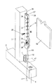
図1イ、ロは第1の実施例であり、木造住宅における軸組の一部である。基礎1に土台2が載置され、土台2に柱3,4が立設され、柱3,4の上端に梁5が架設されている。土台2はアンカーボルト6で基礎1に固定されている。左右の柱3,4の柱脚と柱頭は土台2と梁5に対してほぞを形成して接合されると共に、それぞれの角において小形のL形金物7で結合され、また、土台2に対して左右の柱3,4の柱脚はホールダウン金物8によって緊結されている。
FIGS. 1A and 1B show a first embodiment, which is a part of a framework in a wooden house. A
ホールダウン金物8(図1ロ)は、柱に固定した固定金物9と引寄せボルト10とからなり、引寄せボルト10は土台2を貫通させて基礎1へ新たに固定した追加のアンカーボルト11とジョイントナット12で連結されている。
The hole-down hardware 8 (FIG. 1B) includes a
左右の柱3,4と上下の土台2及び梁5とで壁フレーム13が構成されている。壁フレーム13には、制振装置14が取り付けられる。制振装置14は、木材板の一つである構造用合板から切り出した長方形の伝達板15を左右の柱にそれぞれ長方形の長辺で固定し、左右の伝達板15間がダンパー16で結合されている。
この実施例において、構造用合板は厚さ28mmであり、伝達板15の長辺は2000mm、短辺は350mmとしている。長辺の2000mmは柱2の上辺から梁5の下面間の寸法から上下425mmずつ合計で850mmを差し引いた長さであり、短辺の350mmは、対向して取り付けた伝達板14の内側長辺間に105mmの間隔を取る寸法である。左右の柱3,4の対向面にそれぞれ補助桟17(例えば45×45mm)を固定し、これに伝達板15の柱側長辺を36本の六角スクリュー17(φ6×70mm)を約55mm間隔でねじ込んで固定している。
A
In this embodiment, the structural plywood has a thickness of 28 mm, the long side of the
ダンパー16は、215×400mmの金属プレート19,20を前後に重ねその間に粘弾性部材を充填して接着したものであり、これを上下に2個伝達板15の対向辺間に配置して、それぞれに金属プレート19を一方の伝達板15に、金属プレート20を他方の伝達板15に、それぞれ10本ずつのコーチスクリューで固定したものである。粘弾性部材は100×360×6.9mmの高分子制振材料である。
The
壁フレーム13は、地震力を受けると、柱3,4の柱脚と土台2の接合はほぞとホールダウン構造、柱3,4の柱頭と梁5との接合はほぞと小形L形金物7によるある程度の回転を許容するピン結合であるため、壁フレーム13は左右の柱3,4が左右に傾斜して変形する。
When the
すると、柱3,4と伝達板14を通じて地震力がダンパー15に伝えられ、地震力は粘弾性材内部で消費され、結果として地震力が緩衝される。このとき、柱3,4からダンパー15までは、柱3,4と伝達板14との結合箇所と伝達板14とダンパー15との結合箇所だけであり、結合箇所のすべりなどで変形が分散されてしまう恐れが少ない。また、左右の柱3,4には長方形をして二次断面係数の高い伝達板が固定されているので地震力によって柱3,4が湾曲することも抑制される。これらにより、壁フレーム13に作用する地震力は、接合部の滑りや撓みといった変形の分散を抑えながら、ダンパー16に伝達され、効率よく制振機能が発揮される。
Then, the seismic force is transmitted to the
また、この制振補強された壁フレーム13は、制振装置として長方形の伝達板15とダンパー16を左右の柱間に取り付けるだけなので構造が簡素である。伝達板15も構造用用合板から切り出しただけのしかも簡単な形態のものなので比較的安価あり、かつ、ダンパー16も含めて軸組みを行う作業者が充分に組み付けることができるから、安価に実施できる
特に既存住宅では、室内側から、内壁だけを取外した状態で施行することができ、工事が大掛かりにならず、また、短期間で完了できるので、居住状態のままで施行できる利点がある。
そして、壁フレーム13の構成は伝達板を含め左右対称であるから、壁フレーム13が左右から受ける地震力の作用が均等であり、制振補強された壁フレーム13は住宅として安定な構造である。
The vibration-reinforced
Since the structure of the
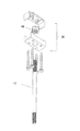
図2は、第2の実施例2を示し、柱脚用の連結金物21,柱頭用の連結金物22及び中間用の連結金物23を用いていることを特徴とする。
壁フレーム13は既存住宅における軸組の一部であり、前記同様に、左右の柱3,4と土台2及び梁5とからなり、土台2はアンカーボルト6により基礎1に固定されている。この施工例は室内側からの改修施工であるため、補強をする目的の壁フレーム13が位置箇所の壁から内壁材だけを除去して、床24と天井25を残している。床24が土台2上に形成されると共に天井25が吊り金物26で梁5から支持されている。
FIG. 2 shows a second embodiment, which is characterized in that a column
The
制振装置14は、伝達板15とこれらをつなぐダンパー16および連結金物21,22,23とからなる。
伝達板15は、構造用合板から長方形に切り出したものである。
柱脚用の連結金物21(図3)は、この実施例において厚さ3.2mmの鋼板を、高さ525mm、左右幅65mm、前後35mmとしたプレス加工品であり、平行に配置された2つの側壁27と側壁28の柱側を連結した取付け壁29とを有する。
The
The
The column base 21 (FIG. 3) is a press-processed product having a thickness of 3.2 mm, a height of 525 mm, a width of 65 mm, and a length of 35 mm in this embodiment. There are two
2つの側壁27,28には上下方向に固定用ボルト30の挿通孔31が双方に貫通して形成されており、これにより2つの側壁27,28はその間に伝達板15を挟み込んで固定する固定部となる。さらに、2つの側壁27,27は長手方向の端部寄りに窓孔32(40×100mm)が双方に貫通して形成されており、引寄せボルト10の一端を係合する係合部とされる。取付け壁29には柱脚用の連結金物21を柱3へ固定するためのビス33(図4、図5)を通す挿通孔34が形成されている。
Insertion holes 31 for fixing
この柱脚用の連結金物21は、既存住宅の改修用であるため、窓孔32の位置が柱3から離れる方向に約25mmだけシフトして形成され、窓孔32(係合部)に配置する引寄せボルト10の位置が柱3の側面から施工時に用いる回転工具の作業用最小必要寸法d1以上の位置となる箇所に形成されている(図6)。すなわち、引寄せボルト10と結合するための追加のアンカーボルト11の差込孔を土台2から基礎1にかけて形成するために使用する回転工具に大きさがあるために、ある距離以上に柱へ近づけて作業をできない(この距離を作業用最小必要寸法d1とする)ためである。追加のアンカーボルト11は、形成された差込孔へ差し込み接着で基礎1と固定される。
Since the column
柱頭用の連結金物22は、柱脚用の連結金物21と同様、両側の側壁27,28とこれらをつなぐ取付け壁29を有する溝形であり、側壁27,28に固定用ボルト30を通す挿通孔31と端部に窓孔32を備えている。ただ、窓孔32の部分は柱脚用の連結金物21のように側方へ張り出すことがなく、側壁27,28の左右幅の範囲に納まっている。
中間の連結金物23は、窓孔32を有しないだけで、柱頭用の連結金物22と同じ構成である。長さは窓孔32を有しない分だけ短く、この実施例において350mmである。
Similar to the column
The
第2の実施例は住宅の室内側から次のように施工される。
まず、目的とする補強箇所の内壁を外して壁フレーム13を露出させ、追加のアンカーボルト11を固定する。左右の柱3,4の柱脚と土台2とを小型のL形金物7で緊結し、接合箇所を引抜きに対して補強する。小形のL形金物7は、柱3,4の傾斜を許容するものであり、主として引抜き耐力に寄与する。
ついで、左右の柱3,4の対向面へ連結金物21,22,23の取付け壁29を直接に当ててそれぞれ複数本のビス33(実施例では17本)で確実に固定する(図4)。柱脚用の連結金物21はその窓孔32を下方として、柱頭用の連結金物22はその窓孔32を上方として固定する。
The second embodiment is constructed as follows from the indoor side of the house.
First, the inner wall of the target reinforcement location is removed, the
Next, the mounting
そして、柱脚用の連結金物21の窓孔32に角座金36(図3)を差し込み、双方の側壁27,28に掛け渡して取り付け、これに引寄せボルト10を差し込んでその上端部に締結ナット37を螺合する。引寄せボルトの10の下端はジョイントナット12を介して追加のアンカーボルト11の上端と連結する。締結ナット37を締め付けて柱3,4の柱脚と土台2を引寄せ、緊結する(図2、図3)。
また、柱頭用の連結金物22の窓孔32へ同様に各座金36を差し込んで取り付け、これに引寄せボルト10の下端部を差し込んで締結ナット37で止め、引寄せボルト10の上端部を端部連結具38と結合する。締結ナット37を締め付けて柱3,4の柱頭と梁5を引寄せ、緊結する。
Then, a square washer 36 (FIG. 3) is inserted into the
Similarly, each
端部連結具38(図7)は、上下に分離された部分を組み合わせることで直方体の容器様となる基体39と、その内部に納めた受けナット40とからなる。基体39を梁5の下面に4本のラグスクリュー41(図41)で固定しておき、下方から引寄せボルト10の上部を差し込んで受けナット40に螺合させる。端部連結具38は、改修施工用に開発されたものであり、残存させた天井25と外壁との隙間から梁5の下面に取り付け、引寄せボルト10を連結できるので、2階の床材を取り除くことなく施工できる。
中間の金物23を柱3,4の中間位置で対抗面に固定する。固定の態様は柱脚用の連結金物21と同様である。
The end connector 38 (FIG. 7) includes a
An
ついで、あらかじめ準備しておいた伝達板15を、連結金物21,22,23の側壁27,28間に柱側の長辺側を差し込んで固定用ボルト30で確実に締め付けて固定する(図1、図4)。これにより、左右の伝達板15が左右の柱3,4のそれぞれと結合される。そして、左右の伝達板15の対向した他の長辺間にダンパー16をその金属プレート19を左の伝達板15に、金属プレート20を右の伝達板15にそれぞれ複数(実施例では、プレート19,20ごとに20本)のラグスクリュー35によって固定する。
Next, the
制振補強された壁フレーム13に地震力が作用すると、壁フレーム13における、柱3,4の柱脚、柱頭と土台2、梁5との結合は、小形のL形金物7と引寄せボルト10を利用したホールダウン構造により、引抜きに対して補強されているが回転が許容されるいわゆるピン結合であるため、柱3,4が傾斜する。すると、地震力は、柱3,4、連結金物21,22,23及び伝達板15を通してダンパー16に伝達され、粘弾性材を変形させる際に熱として消費される。
When a seismic force acts on the vibration-suppressed and reinforced
第2の実施例においても、制振装置14としては、連結金物21,22,23と伝達板15及びダンパー16だけであって、構造が簡素である。また、連結金物21,22,23を用いることは、左右の柱3,4の対向面に補助桟17を切り出して固定するという現場作業を省略できる、柱3,4に対して伝達板15を確実に固定しやすい、現場作業と異なり、連結金物は工場生産なので柱3,4と伝達板15との結合がムラのないものとなる。
Also in the second embodiment, the
連結金物を用いることで、柱3,4と伝達板15とを確実、強固に固定できるので、壁フレーム13の変形をすべりの少ない状態でダンパー16へ伝達することができ、効率のよい制振効果を得ることができる。
柱脚用の連結金物21と柱頭用の連結金物22は、引寄せボルト10の係合部をかねるので、柱脚と土台2及び柱頭と梁との緊結にホールダウン金物の固定金物を別個に取り付ける手間を要しない。
By using the connecting hardware, the
Since the column
図8は第3の実施例であり、壁フレーム13を構成する左右の柱3,4の対向面に一体形の連結金物42を取り付け、これに伝達板15を固定している。
一体形の連結金物42は、第2の実施例における柱脚、柱頭及び中間の連結金物21,22,23を一体に形成したもので上端部及び下端部に引寄せボルト10の係合部となる窓穴32が形成されている。一体形の連結金物42の長さは、梁成や施工箇所の都合によって異なるが、できるだけ長くするのが好ましく、一般に土台上面と梁下面間の寸法(二階の場合は上下の梁間)の大部分に渡るものとする。
FIG. 8 shows a third embodiment, in which an integral connecting
The
他の構成及び施工手順などは第2の実施例と同様である。
なお、この実施例において、柱頭側の引寄せボルト10は、一端を一体形の連結金物42の上部窓孔32に係合させ、他端は、梁5にあらかじめ形成した差込孔に通してその先端のねじ部に梁5の上部から切刃を備えた座金付きナット43を螺合して引寄せ、緊結してある。
Other configurations and construction procedures are the same as in the second embodiment.
In this embodiment, the pulling
第3の実施例では、第1、第2の実施例が発揮する作用効果に加え、連結金物が一体形であることにより、柱3,4と伝達板15との結合状態をより強固なものとできる、一体形の連結金物42が固定されていることにより、地震力による柱3,4の湾曲が抑制されるのと柱頭、柱脚を一体化しているのとで、地震力をさらに効率よくダンパー16に伝達することができる、などの作用効果がある。また、施工に際して取り揃えなければならない部品点数がすくなくなり、現場への資材送り出しの際に間違いが少なくなる。
In the third embodiment, in addition to the functions and effects exhibited by the first and second embodiments, the coupling hardware is integrated so that the coupling state between the
なお、図9イに示すように、壁フレーム13が変形するとき、左右の伝達板15,15を結合しているダンパー16に前面側(あるいは、後面側)が張り出すような傾向(ダンパー箇所における座屈の傾向)の生じることがある(図は、誇張して示している)。これを防止するため、同図ロのように、伝達板15のダンパー16が取付けられる面と反対面をはらみ防止材44で結合することがある。
はらみ防止部材は例えば、一方の伝達板15に一端を固定した丈夫なバー材であり、他端側を他方の伝達板15の面に当接させて摺動可能としている。あるいは、左右の伝達板15,15の上端と下端を厚み方向で挟むチャンネル材であって、左右の伝達板15,15間をつなぐものであっても良い。このチャンネル材は、一端を一方の伝達板15に固定し、他方は伝達板15を挟みながら摺動可能とする。
As shown in FIG. 9A, when the
The anti-jamming member is, for example, a strong bar material having one end fixed to one
以上、実施例を説明した。
連結金物10,42は実施例のように、両側の側壁27,28と取付け壁29とから成る断面コ字形の他に、側壁27,28の柱側縁部を外側に屈曲して折返し、この部分を柱3,4への取付け部としてもよい。さらには、連結金物10,42は、断面がL字形のアングル材とすることもできる。この場合、L字形を形成する垂直部を伝達板15の固定部にすると共に水平部を柱3,4への取付け部にする。垂直部の長手方向端部寄りには、引寄せボルト10の端部を係合する窓孔32を形成する。
ダンパー部材11は粘弾性材を機能部材とするものに限らない。
The embodiment has been described above.
In addition to the U-shaped cross section formed by the
The
1 基礎
2 土台
3 左柱
4 右柱
5 梁
6 アンカーボルト
7 小形のL字形金物
8 ホールダウン金物
9 固定金物
10 引寄せボルト
11 追加のアンカーボルト
12 ジョイントナット
13 壁フレーム
14 制振装置
15 伝達板
16 ダンパー
17 補助桟
18 六角スクリュー
19 金属プレート
20 金属プレート
21 柱脚用の連結金物
22 柱頭用の連結金物
23 中間の連結金物
24 床
25 天井
26 吊り金物
27 側壁(左)
28 側壁(右)
29 取付け壁
30 固定用ボルト
31 挿通孔
32 窓孔
33 ビス
34 挿通孔
35 ネジ
36 角座金
37 締結ナット
38 端部連結具
39 基体
40 受けナット
41 ラグスクリュー
42 一体の連結金物
43 座金付きナット
44 はらみ防止部材
1
28 Side wall (right)
DESCRIPTION OF
Claims (6)
Priority Applications (1)
| Application Number | Priority Date | Filing Date | Title |
|---|---|---|---|
| JP2007190365A JP2009024435A (en) | 2007-07-23 | 2007-07-23 | Wall frame structure reinforced in terms of vibration control performance |
Applications Claiming Priority (1)
| Application Number | Priority Date | Filing Date | Title |
|---|---|---|---|
| JP2007190365A JP2009024435A (en) | 2007-07-23 | 2007-07-23 | Wall frame structure reinforced in terms of vibration control performance |
Related Child Applications (1)
| Application Number | Title | Priority Date | Filing Date |
|---|---|---|---|
| JP2008258244A Division JP5015110B2 (en) | 2008-10-03 | 2008-10-03 | Withdrawal hardware |
Publications (2)
| Publication Number | Publication Date |
|---|---|
| JP2009024435A true JP2009024435A (en) | 2009-02-05 |
| JP2009024435A5 JP2009024435A5 (en) | 2010-09-09 |
Family
ID=40396502
Family Applications (1)
| Application Number | Title | Priority Date | Filing Date |
|---|---|---|---|
| JP2007190365A Pending JP2009024435A (en) | 2007-07-23 | 2007-07-23 | Wall frame structure reinforced in terms of vibration control performance |
Country Status (1)
| Country | Link |
|---|---|
| JP (1) | JP2009024435A (en) |
Cited By (4)
| Publication number | Priority date | Publication date | Assignee | Title |
|---|---|---|---|---|
| JP2011032776A (en) * | 2009-08-04 | 2011-02-17 | Jutaku Kozo Kenkyusho:Kk | Wooden building |
| JP2015215081A (en) * | 2014-05-13 | 2015-12-03 | 富山県 | Frictional damper and wall surface body |
| CN107700705A (en) * | 2017-11-07 | 2018-02-16 | 广州大学 | A kind of assembled energy-dissipating and shock-absorbing filled-in panel structure |
| JP7319006B1 (en) | 2023-03-22 | 2023-08-01 | 有限会社タック・ケン | Building structure |
Citations (5)
| Publication number | Priority date | Publication date | Assignee | Title |
|---|---|---|---|---|
| JP2000054679A (en) * | 1998-08-07 | 2000-02-22 | Onoda Autoclaved Light Weight Concrete Co Ltd | Vibration control structure of building |
| JP2002180693A (en) * | 2000-12-12 | 2002-06-26 | Masa Kenchiku Kozo Sekkeishitsu:Kk | Earthquake resistant structure and earthquake resistant connector |
| JP2002303351A (en) * | 2002-01-30 | 2002-10-18 | Asahi Kasei Corp | Energy absorbing body |
| JP2007046235A (en) * | 2005-08-05 | 2007-02-22 | Eyeful Home Technology Inc | Vibration control panel and building |
| JP2007046239A (en) * | 2005-08-05 | 2007-02-22 | Daiken Trade & Ind Co Ltd | Vibration control structure of building |
-
2007
- 2007-07-23 JP JP2007190365A patent/JP2009024435A/en active Pending
Patent Citations (5)
| Publication number | Priority date | Publication date | Assignee | Title |
|---|---|---|---|---|
| JP2000054679A (en) * | 1998-08-07 | 2000-02-22 | Onoda Autoclaved Light Weight Concrete Co Ltd | Vibration control structure of building |
| JP2002180693A (en) * | 2000-12-12 | 2002-06-26 | Masa Kenchiku Kozo Sekkeishitsu:Kk | Earthquake resistant structure and earthquake resistant connector |
| JP2002303351A (en) * | 2002-01-30 | 2002-10-18 | Asahi Kasei Corp | Energy absorbing body |
| JP2007046235A (en) * | 2005-08-05 | 2007-02-22 | Eyeful Home Technology Inc | Vibration control panel and building |
| JP2007046239A (en) * | 2005-08-05 | 2007-02-22 | Daiken Trade & Ind Co Ltd | Vibration control structure of building |
Cited By (4)
| Publication number | Priority date | Publication date | Assignee | Title |
|---|---|---|---|---|
| JP2011032776A (en) * | 2009-08-04 | 2011-02-17 | Jutaku Kozo Kenkyusho:Kk | Wooden building |
| JP2015215081A (en) * | 2014-05-13 | 2015-12-03 | 富山県 | Frictional damper and wall surface body |
| CN107700705A (en) * | 2017-11-07 | 2018-02-16 | 广州大学 | A kind of assembled energy-dissipating and shock-absorbing filled-in panel structure |
| JP7319006B1 (en) | 2023-03-22 | 2023-08-01 | 有限会社タック・ケン | Building structure |
Similar Documents
| Publication | Publication Date | Title |
|---|---|---|
| KR20150072142A (en) | Building non-welding truss structures | |
| JP2009024435A (en) | Wall frame structure reinforced in terms of vibration control performance | |
| JP2019196634A (en) | Reinforcement member for wooden frame | |
| JP2012102570A (en) | Vibration control device | |
| JP4856520B2 (en) | Vibration control panel | |
| JP5172607B2 (en) | Joint structure of flat column and beam | |
| JP2015074928A (en) | Steel earthquake-resisting wall | |
| JP2009270388A (en) | Vibration control device for building and vibration control structure of building | |
| JP5702345B2 (en) | Connecting wood fittings for construction | |
| JP2009046923A (en) | Vibration control member and wall frame reinforced by means of vibration control | |
| JP5171552B2 (en) | Column and beam joint structure | |
| JP5568343B2 (en) | Vibration control device for wooden buildings | |
| JP5596338B2 (en) | Reinforcing brackets for wooden buildings and methods for reinforcing wooden buildings | |
| JP4904100B2 (en) | Connection structure between building unit and foundation, method for connecting building unit and foundation, and unit building | |
| JP4274082B2 (en) | Seismic reinforcement equipment for buildings | |
| JP5064921B2 (en) | Reinforcing hardware | |
| JP2013060803A (en) | Earthquake-resistant hardware and earthquake-resistant structure using the same | |
| JP6886788B2 (en) | Seismic ceiling structure | |
| JP4970161B2 (en) | Foundation connection hardware and connection structure of foundation and structural material | |
| JP2009256915A (en) | Wall structure of building | |
| JP2012122276A (en) | Damping structure and building | |
| JP5190904B1 (en) | Seismic reinforcement structure for wooden houses | |
| JP4928229B2 (en) | Foundation and pillar connection structure | |
| JP5749663B2 (en) | Column structure | |
| JP5520745B2 (en) | Fastener |
Legal Events
| Date | Code | Title | Description |
|---|---|---|---|
| A521 | Written amendment |
Effective date: 20100722 Free format text: JAPANESE INTERMEDIATE CODE: A523 |
|
| A621 | Written request for application examination |
Effective date: 20100722 Free format text: JAPANESE INTERMEDIATE CODE: A621 |
|
| A977 | Report on retrieval |
Free format text: JAPANESE INTERMEDIATE CODE: A971007 Effective date: 20120309 |
|
| A131 | Notification of reasons for refusal |
Effective date: 20120313 Free format text: JAPANESE INTERMEDIATE CODE: A131 |
|
| A521 | Written amendment |
Free format text: JAPANESE INTERMEDIATE CODE: A523 Effective date: 20120511 |
|
| RD02 | Notification of acceptance of power of attorney |
Free format text: JAPANESE INTERMEDIATE CODE: A7422 Effective date: 20120511 |
|
| A521 | Written amendment |
Effective date: 20120524 Free format text: JAPANESE INTERMEDIATE CODE: A523 |
|
| A131 | Notification of reasons for refusal |
Free format text: JAPANESE INTERMEDIATE CODE: A131 Effective date: 20130212 |
|
| A02 | Decision of refusal |
Free format text: JAPANESE INTERMEDIATE CODE: A02 Effective date: 20130618 |