JP2009017974A - Wheelchair - Google Patents
Wheelchair Download PDFInfo
- Publication number
- JP2009017974A JP2009017974A JP2007181537A JP2007181537A JP2009017974A JP 2009017974 A JP2009017974 A JP 2009017974A JP 2007181537 A JP2007181537 A JP 2007181537A JP 2007181537 A JP2007181537 A JP 2007181537A JP 2009017974 A JP2009017974 A JP 2009017974A
- Authority
- JP
- Japan
- Prior art keywords
- frame
- wheelchair
- attached
- shaft
- seat
- Prior art date
- Legal status (The legal status is an assumption and is not a legal conclusion. Google has not performed a legal analysis and makes no representation as to the accuracy of the status listed.)
- Pending
Links
Images


Landscapes
- Handcart (AREA)
- Carriages For Children, Sleds, And Other Hand-Operated Vehicles (AREA)
Abstract
Description
本発明は、前後方向に入れ子状に嵌合し合って収容する、所謂ネスティングを可能とした車椅子に関する。 The present invention relates to a wheelchair capable of nesting and fitting in a nesting manner in the front-rear direction.
車椅子には、自動車などの車両に搭載するために左右の幅方向に折り畳み可能なタイプ(特許文献1)、全方向に回転可能な前輪を備えた電動タイプ(特許文献2)、座部下側に取り付けたXリンク体で高さ調整可能なタイプ(特許文献3)など、設置される場所や利用者に応じて各種のタイプが開発されている。このような車椅子は、空港、病院、デパート、美術館などの公共の場に設置され、利用者に貸し出されている。 The wheelchair includes a type that can be folded in the left-right width direction to be mounted on a vehicle such as an automobile (Patent Document 1), an electric type that includes a front wheel that can rotate in all directions (Patent Document 2), and a lower part of the seat. Various types have been developed according to the place of installation and the user, such as a type that can be adjusted in height by the attached X-link body (Patent Document 3). Such wheelchairs are installed in public places such as airports, hospitals, department stores, and museums, and are rented out to users.
折り畳み可能な車椅子は、展開時における車幅方向の幅を約半分に縮めるものであるが、座席や背もたれは折り畳み可能な布製のシートが左右のフレーム間に張られて構成されているため、ユーザが着座した際シートが沈んでしまいユーザが楽な姿勢で座ることができず、長時間座っていると疲れが生じるという課題がある。 A foldable wheelchair reduces the width in the vehicle width direction when deployed to about half, but the seat and backrest are constructed with a foldable cloth seat stretched between the left and right frames. When seated, the seat sinks and the user cannot sit in an easy posture, and there is a problem that fatigue occurs when sitting for a long time.
また、公共の場に設置される車椅子を折り畳みタイプにすると、借主である利用者に対して直ぐ提供することができず、そのため、折り畳みタイプの車椅子でも展開した状態で設置されているのが現状である。すると、公共の場の管理者や運営者は、車椅子設置場所のためにスペースを確保する必要があったり、車椅子の整理整頓に手間も掛かる。 In addition, if a wheelchair installed in a public place is of a folding type, it cannot be provided immediately to the borrower user, and as such, it is currently installed in a folded type wheelchair. It is. Then, managers and operators of public places need to secure a space for the wheelchair installation place, and it takes time and effort to organize the wheelchair.
本発明は、上記課題に鑑み、ネスティング可能とし設置スペースを最小限に抑え、利用者及び設置者のニーズに応じた車椅子を提供することを目的とする。 In view of the above problems, an object of the present invention is to provide a wheelchair that can be nested and minimizes installation space and meets the needs of users and installers.
上記目的を達成するため、本発明は、左右の前輪及び背もたれ部が取り付けられる第1フレームと、左右の後輪が取り付けられる第2フレームと、第1フレームに回転可能に取り付けられた座部とを備え、第1フレーム及び第2フレームが車椅子左右の側部に配設される一対の第1フレーム部及び第2フレーム部をそれぞれ有し、各側部において、第1フレーム部と第2フレーム部とが連結部で回動可能にX字状にリンク結合されており、第2フレーム部における連結部より斜め後方に傾斜した後脚フレーム部が、第1フレーム部及び第1フレーム部の下端部に取り付けた前輪より外側に配設され、座部と背もたれ部との間に隙間を形成していることを特徴とする。
この構成により、前後に配置された同じ型の車椅子同士において、前側に配置された車椅子の後輪が、後側に配置された車椅子の前輪と干渉せず、第1フレーム部と第2フレーム部とが干渉しないため、両車椅子をネスティングすることができる。
To achieve the above object, the present invention provides a first frame to which left and right front wheels and a backrest part are attached, a second frame to which left and right rear wheels are attached, and a seat part rotatably attached to the first frame. The first frame and the second frame each have a pair of first and second frame portions disposed on the left and right side portions of the wheelchair, and the first frame portion and the second frame are provided on each side portion. And a rear leg frame part inclined obliquely rearward from the connection part in the second frame part is connected to the lower part of the first frame part and the first frame part. It is arrange | positioned outside the front wheel attached to the part, and the clearance gap is formed between the seat part and the backrest part, It is characterized by the above-mentioned.
With this configuration, in the same type of wheelchairs arranged in the front and rear, the rear wheel of the wheelchair arranged in the front side does not interfere with the front wheel of the wheelchair arranged in the rear side, and the first frame part and the second frame part Both wheelchairs can be nested because they do not interfere with each other.
第1フレーム部と第2フレーム部との間の連結部にトーションバネが取り付けられ、第1フレーム部における前脚フレーム部の端部と第2フレーム部における後脚フレーム部の端部とが前後方向に狭まるよう付勢されていると、スムーズに前後方向に畳むことができる。 A torsion spring is attached to the connecting part between the first frame part and the second frame part, and the end part of the front leg frame part in the first frame part and the end part of the rear leg frame part in the second frame part are in the front-rear direction. When it is urged to narrow, it can be folded in the front-rear direction smoothly.
第2フレームは車幅方向に横たわるシャフトを有するようU字状に形成され、第1フレームには矩形枠状のシートフレームが回動可能に取り付けられ、シートフレームの左右側部にはシャフトを挿通するためのスライドガイドが形成され、トーションバネの付勢力に抗してシャフトをロックするロック機構が取り付けられていると、着座していない状態であっても安定して座席を利用することができる。 The second frame is formed in a U shape so as to have a shaft lying in the vehicle width direction. A rectangular frame-like seat frame is rotatably attached to the first frame, and the shaft is inserted into the left and right sides of the seat frame. If a slide guide is formed and a lock mechanism that locks the shaft against the urging force of the torsion spring is attached, the seat can be used stably even when the seat is not seated. .
ロック機構は、シートフレームの左右一方の側部において軸部で回転可能に取り付けられるロック部材と、ロック部材を付勢するバネと、ロック部材をバネの付勢力に抗して回転させるワイヤーとを備え、ロック部材は、スライドガイドに挿通されたシャフトが前側に変位している状態においてシャフトと係合することでシャフトをロックする一方、ワイヤーでバネの付勢力に抗して回転し、ロック部材との係合が解けシャフトをロック解除する。 The lock mechanism includes: a lock member that is rotatably attached to the left and right sides of the seat frame; a spring that biases the lock member; and a wire that rotates the lock member against the biasing force of the spring. The lock member is locked against the urging force of the spring with a wire while locking the shaft by engaging with the shaft in a state where the shaft inserted through the slide guide is displaced to the front side. The shaft is released and the shaft is unlocked.
後脚フレーム部には軸部を介してペダルが取り付けられ、前脚フレーム部における連結部とペダルとの間にはロッドが取り付けられ、ペダルの先端部が軸部を中心に下向きに押圧されると、ロッドを介して、トーションバネに抗して第1フレームにおける前脚フレーム部の端部と第2フレームにおける後脚フレーム部の端部とが前後方向に広がる。 A pedal is attached to the rear leg frame part via a shaft part, a rod is attached between the connecting part and the pedal in the front leg frame part, and when the tip of the pedal is pressed downward about the shaft part The end portion of the front leg frame portion in the first frame and the end portion of the rear leg frame portion in the second frame spread in the front-rear direction against the torsion spring through the rod.
本発明の車椅子によれば、複数の車椅子を車幅方向に折り畳むことなくネスティングすることで、簡単に設置スペースに整理整頓できるばかりか、利用者の要望に応じて直ちに展開して使用に供することができる。 According to the wheelchair of the present invention, by nesting a plurality of wheelchairs without folding them in the vehicle width direction, the wheelchair can be easily arranged and arranged in the installation space, and can be immediately deployed and used according to the user's request. Can do.
以下、図1〜図5を参照して本発明の好適な第1実施形態を説明し、この第1実施形態を改良した第2形態について図6〜図10を参照して説明する。 A preferred first embodiment of the present invention will be described below with reference to FIGS. 1 to 5, and a second embodiment obtained by improving the first embodiment will be described with reference to FIGS.
(第1実施形態)
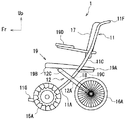
図1は、本発明の第1実施形態に係る車椅子1の前方から見た斜視図であり、図2は図1に示す車椅子1の平面図、図3は図1に示す車椅子1の右側面図、図4は図1に示す車椅子1の背面図である。図中、Frは車椅子の前方を、Upは上方を、Wは車椅子の横幅方向を示す。
(First embodiment)
1 is a perspective view of a
車椅子1は、図示するように、左右一対の前輪15A,15B及び背もたれ部17が取り付けられると共に座部19が回転可能に取り付けられる第1フレーム11と、左右一対の後輪16A,16Bが取り付けられる第2フレーム12と、第1フレーム11と第2フレーム12とを回動可能にX字状にリンク結合する連結部18とでフレーム構成される。第2フレーム12における連結部18より斜め後方に傾斜した後脚フレーム部12A,12B間の車幅方向間隔は、第1フレーム11における連結部18より斜め前方に傾斜した前脚フレーム部12C,12D間のそれより広い。即ち、後脚フレーム部12A,12Bが、第1フレーム11及び第1フレーム11の下端部に取り付けた前輪15A,15Bより外側に配設されている。
As illustrated, the
車椅子1のフレーム構成の具体的な構成は次の通りである。第1フレーム11は、座席フレーム19Aが回転可能に取り付けられ、かつ背もたれ部17の左右両端部が取り付けられる左右一対のフレーム部11C、11Dと、この左右一対のフレーム部11C、11D同士を補強する補強フレーム11Eとでなる。第2フレーム12は、座席前部19Bの下側に配置されるシャフト12Eと、このシャフト12Eの両端から後方に傾斜した左右一対のフレーム部12C、12DとでU字状に一体構成されてなる。第1フレームにおける一対のフレーム部11C,11Dの車幅方向外側に第2フレーム12のフレーム部12C,12Dが配置され、フレーム部11C,11Dとフレーム部12C,12Dとが連結部18でX字状にリンク結合されて、フレーム構成されている。
The specific configuration of the frame configuration of the
第1フレーム11における左右一対のフレーム部11C,11Dには、それぞれ、座席フレーム19Aが軸部19Cで回動可能に取り付けられ、背もたれ部17が固定されている。背もたれ部17の後ろから背もたれ部前方の左右領域それぞれに延出したフレームにアームレスト19Dが取り付けられている。第1の実施形態では左右一対のフレーム部11C,11Dの上端がハンドフレーム11Fで連結し、左右一対のフレーム11C,11Dの下端は左右一対のフットレスト11Gを下支えする支持フレーム11Hで連結している。
A
第1フレーム11における連結部18より前に傾斜した一対の前脚フレーム部11A,11Bの間隔、即ち車幅方向の左右の間隔は、第2フレーム12における連結部18より後に傾斜した一対の後脚フレーム部12A,12Bと比べ狭く、しかも、左右の前脚フレーム部11A,11Bの外側に前輪15A,15Bがそれぞれ取り付けられ、左右の後脚フレーム部12A,12Bの外側に後輪16A,16Bがそれぞれ取り付けられている。また、座部19と背もたれ部17との間には隙間20が設けられている。この隙間20は、後ろ側に配置されている別の車椅子1における座部19が挿入されたり、引き出されたりするための開口を第1フレーム11と共に形成している。
The distance between the pair of front
以上のようにしてフレーム構成され、座部19と背もたれ部17との間に隙間20が設けられているため、図5(A)に示すように、前後に車椅子1,1を配置し前後の車椅子1,1同士を重ねようとする際、前側の車椅子1における後輪16A,16B及び後脚フレーム部12A,12Bが、後側の車椅子1における前輪15A,15B及び前脚フレーム部11A,11Bと干渉しないで図5(B)に示すように重ね合わせできる。つまり、前輪15A,15B、後輪16A,16B、前脚フレーム部11A,11B及び後脚フレーム部12B,12Bが相互に干渉しないので、複数の車椅子2,2を前後方向に重ね合わせできる。
Since the frame is configured as described above and the
第1実施形態では、車椅子1の前輪15A,15Bとして、従来用いられてきた一般的なキャスターではなく、全方位車輪を採用することで、着座者の足下の空間が広く、前輪15A,15Bの径がキャスターより大きくすることができるので車椅子走行時に段差などがあってもハンドフレーム11Fを押す力を軽減することができる。一方、車椅子1の後輪16A,16Bとしては、ディスクブレーキタイプのゴムタイヤを採用し、着座者に対するクッションの役目を果たすことができる。
In the first embodiment, the
(第2実施形態)
図6は第2実施形態に係る車椅子2の側面図であり、(A)はロック機構27を解除する前の状態、(B)はロック機構27を解除した後の状態を示す。第2実施形態は、第1実施形態において車椅子の前後方向に折り畳みできる点で異なる。以下、図6の部分拡大図をそれぞれ示しながら具体的に説明する。なお、同一又は対応する部材には同一の符号を付し説明を省略する。
(Second Embodiment)
6A and 6B are side views of the
図7は、図6において第1フレーム11と第2フレーム12とをX字状につなげた連結部18近傍と、第2フレームにおける後脚フレーム部の一部の部分拡大図で、(A)は後方からの斜視図、(B)は前側からの斜視図である。なお、第1フレームにおける補強フレームは図示していない。図7に示すように、連結部18近傍における第1フレーム11と第2フレーム12との間にトーションバネ21が取り付けられる。具体的には、図示するように、トーションバネ21の螺旋内に連結部18が挿通され、トーションバネ21の一端部が第1フレーム11に取り付けられ、他端部が第2フレーム12に取り付けられる。常に第1フレーム11の下端と第2フレーム12の下端の前後間隔が狭まるように付勢されている。また、第2フレーム12における後脚フレーム部12A,12Bの下端部近傍に軸部22Aを介してペダル22が取り付けられ、ペダル22の上部と第1フレーム11における連結部18近傍との間にロッド23が配設されている。
FIG. 7 is a partially enlarged view of the vicinity of the connecting
第2実施形態での車椅子2の座部は、図6に示すように、第1フレーム11における左右一対のフレーム部11C,11Dに回転可能に取り付けられるシートフレーム24と、シートフレーム24上に取り付けられるシートクッション26とで構成されている。シートフレーム24は、第1フレーム11のフレーム部11C,11Dに回転可能に取り付けられる左右一対の側部24Bと左右一対の側部24Bの前端同士をそれぞれ連結する前部24Aと、左右一対の側部24Bの後端同士をそれぞれ連結する後部24Cとで矩形枠状に形成されている。
As shown in FIG. 6, the seat portion of the
図8は、図6に示す第2実施形態の車椅子2に設けられたロック機構27を示し、シートフレーム24の右前側近傍と第1フレーム11のハンドフレーム11F近傍との部分拡大図である。図9は図8に示すロック機構27の部品を示し、(A)はロック部材28の側面図、(B)はロック部材28の正面図、(C)はロック機構27の一部の分解図である。図10はロック機構27の作用を示し、(A)はロック状態、(B)はロック解除時、(C)ロック解除後の状態を示す図である。
FIG. 8 shows the
シートフレーム24の左右側部24Bにはその辺に沿ってそれぞれスライドガイド24D、即ち長穴が形成され、それぞれのスライドガイド24Dに第2フレーム12のシャフト12Eが挿通されている。
左右何れかのスライドガイド24Dにおいて、図8に示すように、そのスライドガイド24Dを画成する側部24B、即ち穴周縁後端のガイド形成部25Eにロック部材28が跨るように、ロック部材28が回転可能に軸部27Aでシートフレーム24に取り付けられている。シートフレーム24においてスライドガイド24Dより前側にはロック部材28に上側又は下側から当接する戻しバネ29が取り付けられている(図10参照)。戻しバネ29には板バネや棒バネを採用することができる。
Slide guides 24D, that is, elongated holes are formed along the sides of the left and right side portions 24B of the
In either the left or right slide guide 24D, as shown in FIG. 8, the
図9に示すように、ロック部材28はガイド形成部24Eに跨がるよう断面U字状に形成されている。ロック部材28の前端部28Aはシャフト12Eの外形に沿って丸みなどの係合部が形成され、後端部28Cには軸穴28Cが形成され、前端部28Aと後端部28Bとの間には、後述するワイヤー30の先端に取り付けられた円柱ピン30Bを挿入する挿入口28Dと、円柱ピン30Bを軸支える保持孔28Eが形成されている。このワイヤー30には両端部を除いて被覆体30Aが取り付けられ、図8に示すように、被覆体30Aの一端側は、シートフレーム24の側部内側に取り付けたワイヤーストッパー31で固定されている。このワイヤー30は、図6に示すように、シートフレーム24の側部24Bに沿って後方に配線され、第1フレーム11におけるフレーム部11Cに沿って上方に向けて配線にされ、ワイヤー30の他端がハンドフレーム11Fまで配線されている。このワイヤー30の他端は、図8に示すように、取付部材32を介してハンドフレーム11Fに取り付けられた折り畳みレバー33に固着されている。図示する矢印方向に折り畳みレバー33の回転力が付与されると、ワイヤー30が引っ張られる。
As shown in FIG. 9, the
図6及び図10を参照しながら、第2実施形態における車椅子2、特にロック機構27の作用について説明する。
図6(A)に示すように、車椅子利用時では、ロック機構27は図10(A)に示すように、第2フレーム12のシャフト12Eがスライドガイド24Dとロック部材28との間に嵌まっている。これで、図7に示すトーションバネ21による第1フレーム11の下端と第2フレーム12の下端との前後間隔が狭まることを阻止している。
The operation of the
As shown in FIG. 6A, when the wheelchair is used, the
車椅子利用が終了すると、車椅子補助者や公共の場の管理者や介添人など(以下、「利用者」という。)により車椅子2を前後に折り畳んだり、ネスティングする際、ハンドフレーム11Fに取り付けた折り畳みレバー33を軸部周りに回転させ、図8に示す矢印方向に力が加わると、図10(B)に示すように、ロック部材28が取付軸部周りに回転し、戻しバネ29のバネ力に抗してロック部材28が回転し、シャフト12Eがロック部材28で前方向に押されなくなる。すると、図7に示すトーションスプリング21で、第1フレーム11、第2フレーム12同士が相互に回転し始め、図10(B)に示すようにシャフト12Eが背もたれ部17側に移動し始める。これで、車椅子2は図6(B)に示すように前後の間隔が狭まる。この際、前輪15A,15Bと後輪16A,16Bとは干渉しないで、左右の後輪16A,16Bの間に左右の前輪15A,15Bの一部が入り込む状況となる。この状態では、シートクッション26及びシートフレーム24でなる座部は図6(B)のように前後方向に傾斜しているので、同じ型の車椅子同士をネスティングすることができる。即ち、前側の車椅子2における背もたれ部17と座部との間の隙間、即ち開口に、後から後側の車椅子の座部を挿入することができる。
When the use of the wheelchair is finished, the
一方、図6(B)に示すように前後方向に畳まれた車椅子2を利用する際には、先ず、利用者は第1フレーム11のハンドフレーム11Fを把持し、ペダル22を下側に押し下げる。すると、連結部18を中心に第1フレーム11及び第2フレーム12が展開され、左右一対の前輪15A,15Bが前に進む。これで、第2フレーム12のシャフト12Eが図10(C)に矢印の方向に進み、戻りバネ29に抗してロック部材28が軸部周りに回転し、第2フレーム12のシャフト12Eがスライドガイド24Dとロック部材28との間に嵌まる。これにより車椅子2に安定して座ることができる。
On the other hand, when using the
本発明の実施形態では、以上説明したように車椅子1,2を前後に畳むことができるため、座席のシートクッション26や背もたれ部17には、シートや布製でなく、スポンジを含んだクッション部材を採用することができる。そのため、比較的長時間座っていても着座者は疲れを生じず、安定性もよい。また本実施形態における車椅子1,2はネスティングすることができるので、公共の場の管理者や運営者にとっては複数の車椅子を設置するためのスペースを最小限に抑えることができる。特に、第2実施形態ではロック機構27や折り畳みレバー33を設けているため、容易にネスティング作業などの整理整頓の作業を効率よく行うことができる。
In the embodiment of the present invention, since the
本発明の実施形態、特に図面に示した車椅子の構成部材は形状などに変更を加えて、本発明の要旨の範囲で実施することができる。例えば、第2形態で示したロック機構において、ロック部材はスライドガイドに上から跨るように配置されているが、下からスライドガイド形成部に跨るように配置されてもよい。 The components of the wheelchair shown in the embodiments of the present invention, particularly the drawings, can be carried out within the scope of the present invention by changing the shape and the like. For example, in the lock mechanism shown in the second embodiment, the lock member is disposed so as to straddle the slide guide from above, but may be disposed so as to straddle the slide guide forming portion from below.
1、2:車椅子
11:第1フレーム
11A、11B前脚フレーム部
11C、11Dフレーム部
11E補強フレーム
11F:ハンドフレーム
11G:フットレスト
11H:支持フレーム
12:第2フレーム
12A、12B:後脚フレーム部
12C、12D脚フレーム部
12E:シャフト
15A、15B::前輪
16A、16B:後輪
17:背もたれ部
18:連結部
19:座部
19A:座席フレーム
19B:座席前部
19C:軸部
19D:アームレスト
20:隙間
21:トーションバネ
22ペダル
22A:軸部
23:ロッド
24:シートフレーム
24A:前部
24B:側部
24C:後部
24D::スライドガイド
24E:ガイド形成部
26シートクッション
27:ロック機構
27A:軸部
28:ロック部材
28A:前端部
28B:後端部
28C:軸穴
28D:挿入口
28E:保持孔
29:戻しバネ
30:ワイヤー
30A:被覆体
30B:円柱ピン
31:ワイヤーストッパー
32:取付部材
33:折り畳みレバー
1, 2: Wheelchair 11:
Claims (5)
上記第1フレームが車椅子左右の側部に配設される一対の第1フレーム部を有し、
上記第2フレームが車椅子左右の側部に配設される一対の第2フレーム部を有し、
各側部において、第1フレーム部と第2フレーム部とが連結部で回動可能にX字状にリンク結合されており、
上記第2フレーム部における上記連結部より斜め後方に傾斜した後脚フレーム部が、上記第1フレーム部及び該第1フレーム部の下端部に取り付けた前輪より外側に配設され、
上記座部と上記背もたれ部との間に隙間を形成していることを特徴とする、車椅子。 A first frame to which left and right front wheels and a backrest part are attached; a second frame to which left and right rear wheels are attached; and a seat part rotatably attached to the first frame;
The first frame has a pair of first frame portions disposed on the left and right side portions of the wheelchair,
The second frame has a pair of second frame portions disposed on the left and right side portions of the wheelchair,
In each side portion, the first frame portion and the second frame portion are linked in an X shape so as to be rotatable at the connecting portion,
A rear leg frame portion inclined obliquely rearward from the connecting portion in the second frame portion is disposed outside a front wheel attached to the first frame portion and a lower end portion of the first frame portion;
A wheelchair characterized in that a gap is formed between the seat portion and the backrest portion.
前記第1フレームには矩形枠状のシートフレームが回動可能に取り付けられ、
上記シートフレームの左右側部には上記シャフトを挿通するためのスライドガイドが形成され、
前記トーションバネの付勢力に抗して上記シャフトをロックするロック機構が取り付けられていることを特徴とする、請求項2に記載の車椅子。 The second frame is formed in a U shape so as to have a shaft lying in the vehicle width direction,
A rectangular frame-like seat frame is rotatably attached to the first frame,
Slide guides for inserting the shaft are formed on the left and right sides of the seat frame,
The wheelchair according to claim 2, wherein a lock mechanism for locking the shaft against an urging force of the torsion spring is attached.
上記ロック部材は、前記スライドガイドに挿通されたシャフトが前側に変位している状態においてシャフトと係合することで該シャフトをロックする一方、上記ワイヤーで上記バネの付勢力に抗して回転し、上記ロック部材との係合が解け該シャフトをロック解除することを特徴とする、請求項3に記載の車椅子。 The lock mechanism includes a lock member that is rotatably attached to a shaft portion on one of the left and right sides of the seat frame, a spring that urges the lock member, and the lock member that resists the urging force of the spring. With a rotating wire,
The lock member locks the shaft by engaging with the shaft in a state where the shaft inserted through the slide guide is displaced forward, and rotates against the urging force of the spring with the wire. The wheelchair according to claim 3, wherein the shaft is unlocked when the engagement with the lock member is released.
前記前脚フレーム部における前記連結部と上記ペダルとの間にはロッドが取り付けられ、
上記ペダルの先端部が上記軸部を中心に下向きに押圧されると、上記ロッドを介して、前記トーションバネに抗して前記第1フレームにおける前脚フレーム部の端部と前記第2フレームにおける後脚フレーム部の端部とが前後方向に広がることを特徴とする、請求項2に記載の車椅子。 A pedal is attached to the rear leg frame part via a shaft part,
A rod is attached between the connecting part and the pedal in the front leg frame part,
When the front end portion of the pedal is pressed downward about the shaft portion, the end portion of the front leg frame portion in the first frame and the rear portion in the second frame are opposed to the torsion spring via the rod. The wheelchair according to claim 2, wherein an end portion of the leg frame portion extends in the front-rear direction.
Priority Applications (1)
| Application Number | Priority Date | Filing Date | Title |
|---|---|---|---|
| JP2007181537A JP2009017974A (en) | 2007-07-10 | 2007-07-10 | Wheelchair |
Applications Claiming Priority (1)
| Application Number | Priority Date | Filing Date | Title |
|---|---|---|---|
| JP2007181537A JP2009017974A (en) | 2007-07-10 | 2007-07-10 | Wheelchair |
Publications (1)
| Publication Number | Publication Date |
|---|---|
| JP2009017974A true JP2009017974A (en) | 2009-01-29 |
Family
ID=40358139
Family Applications (1)
| Application Number | Title | Priority Date | Filing Date |
|---|---|---|---|
| JP2007181537A Pending JP2009017974A (en) | 2007-07-10 | 2007-07-10 | Wheelchair |
Country Status (1)
| Country | Link |
|---|---|
| JP (1) | JP2009017974A (en) |
Cited By (2)
| Publication number | Priority date | Publication date | Assignee | Title |
|---|---|---|---|---|
| WO2015103237A1 (en) * | 2013-12-31 | 2015-07-09 | Medline Industries, Inc. | Nesting wheeled personal conveyances |
| USD789256S1 (en) | 2014-12-30 | 2017-06-13 | Medline Industries, Inc. | Wheeled personal conveyance |
Citations (10)
| Publication number | Priority date | Publication date | Assignee | Title |
|---|---|---|---|---|
| JPS6094220U (en) * | 1983-12-05 | 1985-06-27 | 株式会社マンテン | wheelchair |
| JPS63214258A (en) * | 1987-03-02 | 1988-09-06 | 田中 美穂 | Automatic folding and developing device of wheelchair |
| JPS6485649A (en) * | 1987-09-29 | 1989-03-30 | Kisaku Koubou Kk | Manual pushing type reclining wheelchair |
| JPH06428U (en) * | 1992-06-18 | 1994-01-11 | 日進医療器株式会社 | Sitting wheelchair |
| US6315306B1 (en) * | 1997-09-12 | 2001-11-13 | Csia Research Foundation | Nestable wheelchair |
| JP2002263142A (en) * | 2001-03-12 | 2002-09-17 | Nishimoto Koichi | Wheelchair |
| JP2003088440A (en) * | 2001-09-18 | 2003-03-25 | Charming Age Kenkyusho:Kk | Stackable mobile chair |
| US20030090073A1 (en) * | 2001-10-30 | 2003-05-15 | Whang Chih Chiang | Wheelchair |
| JP2004090757A (en) * | 2002-08-30 | 2004-03-25 | Satsuki:Kk | Foldable barrow |
| JP2004344289A (en) * | 2003-05-21 | 2004-12-09 | Kanto Auto Works Ltd | Four-wheeled electric wheelchair |
-
2007
- 2007-07-10 JP JP2007181537A patent/JP2009017974A/en active Pending
Patent Citations (10)
| Publication number | Priority date | Publication date | Assignee | Title |
|---|---|---|---|---|
| JPS6094220U (en) * | 1983-12-05 | 1985-06-27 | 株式会社マンテン | wheelchair |
| JPS63214258A (en) * | 1987-03-02 | 1988-09-06 | 田中 美穂 | Automatic folding and developing device of wheelchair |
| JPS6485649A (en) * | 1987-09-29 | 1989-03-30 | Kisaku Koubou Kk | Manual pushing type reclining wheelchair |
| JPH06428U (en) * | 1992-06-18 | 1994-01-11 | 日進医療器株式会社 | Sitting wheelchair |
| US6315306B1 (en) * | 1997-09-12 | 2001-11-13 | Csia Research Foundation | Nestable wheelchair |
| JP2002263142A (en) * | 2001-03-12 | 2002-09-17 | Nishimoto Koichi | Wheelchair |
| JP2003088440A (en) * | 2001-09-18 | 2003-03-25 | Charming Age Kenkyusho:Kk | Stackable mobile chair |
| US20030090073A1 (en) * | 2001-10-30 | 2003-05-15 | Whang Chih Chiang | Wheelchair |
| JP2004090757A (en) * | 2002-08-30 | 2004-03-25 | Satsuki:Kk | Foldable barrow |
| JP2004344289A (en) * | 2003-05-21 | 2004-12-09 | Kanto Auto Works Ltd | Four-wheeled electric wheelchair |
Cited By (5)
| Publication number | Priority date | Publication date | Assignee | Title |
|---|---|---|---|---|
| WO2015103237A1 (en) * | 2013-12-31 | 2015-07-09 | Medline Industries, Inc. | Nesting wheeled personal conveyances |
| US9730846B2 (en) | 2013-12-31 | 2017-08-15 | Medline Industries, Inc. | Nesting wheeled personal conveyances |
| USD789256S1 (en) | 2014-12-30 | 2017-06-13 | Medline Industries, Inc. | Wheeled personal conveyance |
| USD834462S1 (en) | 2014-12-30 | 2018-11-27 | Medline Industries, Inc. | Wheeled personal conveyance |
| USD859225S1 (en) | 2014-12-30 | 2019-09-10 | Medline Industries, Inc. | Wheeled personal conveyance |
Similar Documents
| Publication | Publication Date | Title |
|---|---|---|
| TW544419B (en) | Stroller | |
| KR20050116816A (en) | Seat back recliner for vehicles | |
| JPH11244082A (en) | Vehicle seat | |
| JP2009017974A (en) | Wheelchair | |
| JP5272724B2 (en) | Vehicle seat | |
| JP4652266B2 (en) | Walking assistance vehicle | |
| JP6397522B2 (en) | Frame structure, wheelchair, stroller & chair | |
| JP4567610B2 (en) | wheelchair | |
| JP3183656B2 (en) | Casters | |
| JP3768428B2 (en) | Vehicle seat | |
| JP4976041B2 (en) | Wheel mounting structure for walking assistance vehicles | |
| JP3211180B2 (en) | Jumping stool | |
| JP3992696B2 (en) | wheelchair | |
| JP5272723B2 (en) | Vehicle seat | |
| JP3111185B1 (en) | Operation lever device and light vehicle using the same | |
| JP2005118144A (en) | Folding wheelchair | |
| JP2008246197A (en) | Wheelchair with shift assisting function | |
| JP4996374B2 (en) | Wheelchair footrest fixture | |
| JP2005328980A (en) | Reclining handrail for wheelchair | |
| TW202228623A (en) | Wheelchair | |
| JP4059311B2 (en) | Lock mechanism | |
| JP3993859B2 (en) | Body unit connection structure of the body for electric vehicles | |
| JP2006109878A (en) | Backrest mechanism and wheelchair equipped with the same | |
| JP2021040986A (en) | wheelchair | |
| JP2001010380A (en) | Child seat-built-in type seat |
Legal Events
| Date | Code | Title | Description |
|---|---|---|---|
| A977 | Report on retrieval |
Free format text: JAPANESE INTERMEDIATE CODE: A971007 Effective date: 20100311 |
|
| A131 | Notification of reasons for refusal |
Free format text: JAPANESE INTERMEDIATE CODE: A131 Effective date: 20100316 |
|
| A521 | Written amendment |
Free format text: JAPANESE INTERMEDIATE CODE: A523 Effective date: 20100517 |
|
| A02 | Decision of refusal |
Free format text: JAPANESE INTERMEDIATE CODE: A02 Effective date: 20101026 |