JP2005328980A - Reclining handrail for wheelchair - Google Patents
Reclining handrail for wheelchair Download PDFInfo
- Publication number
- JP2005328980A JP2005328980A JP2004149240A JP2004149240A JP2005328980A JP 2005328980 A JP2005328980 A JP 2005328980A JP 2004149240 A JP2004149240 A JP 2004149240A JP 2004149240 A JP2004149240 A JP 2004149240A JP 2005328980 A JP2005328980 A JP 2005328980A
- Authority
- JP
- Japan
- Prior art keywords
- armrest
- wheelchair
- handrail
- backrest frame
- reclining
- Prior art date
- Legal status (The legal status is an assumption and is not a legal conclusion. Google has not performed a legal analysis and makes no representation as to the accuracy of the status listed.)
- Pending
Links
Images


Abstract
Description
本発明は、リクライニング可能な車椅子の手摺りに関するものである。 The present invention relates to a handrail for a reclining wheelchair.
従来のリクライニング可能な車椅子に具備されている手摺りには、次のようなものがある。
まず、車椅子をリクライニングさせても手摺りが動かないものがある。これには、車椅子のステップ部材や背凭れ部材が取付けられているフレーム本体の側部に車椅子側部が開放可能となるように回動可能に手摺りが取付けられているものがある。また、この手摺りはリクライニング状態において車椅子側部から利用者が転落することを防止するため、背凭れ部材が起立状態における側面視において背凭れ部材の後方へ張り出す大きなものとされている(特許文献1参照。)。
しかしながら、この形態の手摺りは、上述したように、車椅子側部を開放することができるという利点はあるが、リクライニングさせた際に利用者が車椅子側部から転落することを防止するために、手摺りを大きなものとしており、手摺りが車椅子の全体としての大きさや重量に影響し、車椅子の使い勝手に悪影響を及ぼす問題がある。
The handrails provided in the conventional reclining wheelchair include the following.
First, there is a handrail that does not move even when the wheelchair is reclined. In some of them, a handrail is attached to the side of the frame main body to which the step member or the backrest member of the wheelchair is attached so that the side of the wheelchair can be opened. In addition, this handrail has a large backrest member that protrudes backward from the backrest member in a side view in a standing state in order to prevent the user from falling from the side of the wheelchair in the reclining state (patent) Reference 1).
However, the handrail of this form has an advantage that the wheelchair side can be opened as described above, but in order to prevent the user from falling from the wheelchair side when reclining, There is a problem that the handrail is large, and the handrail affects the overall size and weight of the wheelchair, which adversely affects the usability of the wheelchair.
また、上述したものとは異なり、車椅子のリクライニングに追従して手摺りが動作するものがある。これには、背凭れ部材にアームレストの一端が枢結され、座席部材にリンク片の一端が枢結され、アームレストとリンク片が枢結されて、アームレストとリンク片とで手摺りが構成されているものがある(特許文献2参照)。これは、リクライニングに追従して手摺りが移動することで、背凭れ部材が起立状態において車椅子側部から利用者が転落することを防止できる大きさの手摺りで、リクライニング状態においても利用者の車椅子側部からの転落を防止することができるようにされている。
しかしながら、この形態の手摺りは、背凭れ部材が起立状態にあるとき車椅子側部を開放するように動作させることができず、車椅子からベッド等への移乗の際に手摺りが邪魔となる問題がある。また、この形態の手摺りであれば、背凭れ部材と座席部材が同一平面を形成するぐらいまで背凭れ部材をリクライニングさせると、手摺りが車椅子側部を開放するように動作させることができると考えられる。しかし、移乗の際に、車椅子をリクライニングさせる操作が必要となるのは操作上煩わしいだけでなく、利用者にとっても背中の保持ができないので負担がかかるという問題がある。
However, this type of handrail cannot be operated so as to open the side part of the wheelchair when the backrest member is in the standing state, and the handrail becomes an obstacle when transferring from the wheelchair to the bed or the like. There is. Also, with this type of handrail, when the backrest member is reclined to the extent that the backrest member and the seat member form the same plane, the handrail can be operated to open the wheelchair side. Conceivable. However, it is not only troublesome for the user to reclin the wheelchair when transferring, but there is also a problem that the user cannot hold the back and is burdened.
そこで、本発明は上記事情を鑑みて、車椅子のリクライニングに追従して移動可能、かつ、車椅子のリクライニングに関係なく車椅子側部を開放できるリクライニング可能な車椅子の手摺りを提供することを課題とする。 Therefore, in view of the above circumstances, the present invention has an object to provide a handrail for a reclining wheelchair that can move following the reclining of a wheelchair and that can open a side portion of the wheelchair regardless of the reclining of the wheelchair. .
請求項1の発明は、リクライニングが可能な車椅子の両側部に具備される手摺りにおいて、アームレストを支持リンクにて車椅子側部に回動可能に具備させるとともに、アームレストを車椅子の背凭れフレームに係止手段にて任意に係止または係止解除可能とし、アームレストが背凭れフレームに係止された状態において、車椅子のリクライニング動作時に係止手段を中心にアームレストが背凭れフレームに対して回動可能としたことを特徴とする。
請求項2の発明は、アームレストが背凭れフレームに係止された状態において、車椅子のリクライニング動作時に係止手段が背凭れフレームまたはアームレストに沿って摺動可能としたことを特徴とする。
請求項3の発明は、支持リンクを四節リンクとしたことを特徴とする。
請求項4の発明は、背凭れフレームまたはアームレストに係止される部材となる係止部材が弾性体にて軸受筒から常に突出する方向に付勢されるように、該係止部材を軸受筒に係止した係止手段にて、背凭れフレームとアームレストを係止するようにしたことを特徴とする。
According to the first aspect of the present invention, in the handrail provided on both sides of the reclining wheelchair, the armrest is rotatably provided on the side of the wheelchair by the support link, and the armrest is associated with the backrest frame of the wheelchair. Locking means can be arbitrarily locked or unlocked by the locking means, and when the armrest is locked to the backrest frame, the armrest can rotate with respect to the backrest frame around the locking means during the reclining operation of the wheelchair It is characterized by that.
The invention of
The invention of
The invention according to claim 4 is characterized in that the locking member is a bearing cylinder so that the locking member to be locked to the backrest frame or the armrest is urged by the elastic body in a direction that always protrudes from the bearing cylinder. The backrest frame and the armrest are locked by the locking means locked to.
請求項1の発明によれば、アームレストを支持リンクにて車椅子側部に回動可能に具備させるとともに、アームレストを車椅子の背凭れフレームに係止手段にて任意に係止または係止解除可能とした。これによると、アームレストと背凭れフレームとの係止を解除することで、支持リンクにてアームレストを回動させることができるようになり、車椅子側部を任意に開放することができ、車椅子側部からベッド等への移乗を至便に行うことができる。また、アームレストが背凭れフレームに係止された状態において、車椅子のリクライニング動作時に係止手段を中心にアームレストが背凭れフレームに対して回動可能とした。これによると、車椅子のリクライニングに支持リンクによるアームレストの回動を追従させることができ、車椅子のリクライニングに追従して手摺りを移動できる。よって、背凭れフレームが起立状態において車椅子側部からの利用者の転落を防止できる大きさの手摺りで、リクライニング状態においても車椅子側部からの利用者の転落を防止することができる。また、車椅子を全体としてコンパクトに構成することができる。 According to the first aspect of the present invention, the armrest can be rotatably provided on the side of the wheelchair by the support link, and the armrest can be arbitrarily locked or unlocked by the locking means on the backrest frame of the wheelchair. did. According to this, by releasing the lock between the armrest and the backrest frame, the armrest can be rotated by the support link, and the wheelchair side part can be arbitrarily opened, and the wheelchair side part can be opened. Transfer to a bed etc. can be done conveniently. Further, in a state where the armrest is locked to the backrest frame, the armrest is rotatable with respect to the backrest frame around the locking means during the reclining operation of the wheelchair. According to this, the rotation of the armrest by the support link can be made to follow the reclining of the wheelchair, and the handrail can be moved following the reclining of the wheelchair. Therefore, the handrail is of a size that can prevent the user from falling from the side of the wheelchair when the backrest frame is standing, and the user can be prevented from falling from the side of the wheelchair even in the reclining state. In addition, the wheelchair can be configured compactly as a whole.
また、請求項2の発明によると、アームレストが背凭れフレームに係止された状態において、車椅子のリクライニング動作時に係止手段が背凭れフレームまたはアームレストに沿って摺動可能とした。これによると、アームレストと支持リンクと車椅子とで平行リンクを形成していない場合や、背凭れフレームの回動中心の位置が車椅子と支持リンクとの枢結部を含む直線上に常に位置しない場合、または、背凭れフレームとアームレストが係止手段にて係止される位置がアームレストと支持リンクとの枢結部を含む直線上に常に位置しない場合等においても、背凭れフレームとアームレストが係止手段にて係止される位置とアームレストと支持リンクの枢結部との位置関係を常に一定に保つように係止手段が背凭れフレームまたはアームレストを摺動できる。よって、車椅子のリクライニングに支持リンクによるアームレストの回動を追従させることができるようになり、車椅子のリクライニングに追従して手摺りを移動させることができる。
According to the invention of
また、請求項3の発明によると、支持リンクを四節リンクとした。これによると、手摺りと背凭れフレームとの係止を解除した場合においても、アームレストを移動させる際に所定の動作軌跡で移動させることができる。特に、車椅子の側部を開放した状態から手摺りとして機能を果たす状態へ手摺りを戻す際に、支持リンクにて回動できる方向へアームレストを回動させるだけの簡便な操作で、アームレストと背凭れフレームを係止手段にて係止できる位置へアームレストを移動させることができる。
According to the invention of
さらに、請求項4によると、背凭れフレームまたはアームレストに係止される部材となる係止部材を弾性体にて軸受筒から常に突出する方向に付勢させるとともに、該係止部材を軸受筒に係止した係止手段にて背凭れフレームとアームレストを係止するようにした。これによると、アームレストが背凭れフレームに係止されていない状態から支持リンクにてアームレストを回動させると、係止部材が背凭れフレームまたはアームレストに接触することで軸受筒内に収納され、そして、その状態でアームレストの移動がさらに進み、係止部材が背凭れフレームまたはアームレストに係止される部分に位置すると、弾性体の付勢力にて係止部材が軸受筒から突出し、アームレストと背凭れフレームを係止することができる。すなわち、この係止手段によると、アームレストを背凭れフレームとアームレストが係止された状態へ戻す方向へ移動させるだけの簡便な操作で、アームレストと背凭れフレームを係止させることができる。 According to the fourth aspect of the present invention, the locking member that is locked to the backrest frame or the armrest is urged by the elastic body in a direction that always protrudes from the bearing cylinder, and the locking member is attached to the bearing cylinder. The backrest frame and the armrest are locked by the locked locking means. According to this, when the armrest is rotated by the support link from the state where the armrest is not locked to the backrest frame, the locking member comes into contact with the backrest frame or the armrest and is stored in the bearing cylinder, and In this state, when the movement of the armrest further proceeds and the locking member is positioned at a portion where the locking member is locked to the backrest frame or the armrest, the locking member protrudes from the bearing cylinder by the biasing force of the elastic body, and the backrest and the armrest The frame can be locked. In other words, according to this locking means, the armrest and the backrest frame can be locked by a simple operation that simply moves the armrest in a direction to return the backrest frame and the armrest to the locked state.
リクライニング可能な車椅子の両側部に具備される手摺りにおいて、アームレストを四節リンクとした支持リンクにて車椅子側部に回動可能に具備する。さらに、アームレストの後端部に、車椅子の背凭れフレームに係止される部材となる係止部材を弾性体にて軸受筒から常に突出する方向に付勢させるとともに、該係止部材を軸受筒に係止した係止手段を具備する。また、この係止手段を車椅子の背凭れフレームとアームレストとの係止を任意に係止または係止解除可能なものとする。さらに、背凭れフレームとアームレストが係止手段にて係止された状態において、車椅子のリクライニング動作時に、係止手段の係止部材を中心にアームレストが背凭れフレームに対して回動可能とするとともに、係止手段の係止部材が背凭れフレームに沿って摺動可能とする。 In the handrail provided on both sides of the reclining wheelchair, the armrest is provided on the side of the wheelchair by a support link having a four-bar link. Further, the locking member, which is a member locked to the backrest frame of the wheelchair, is urged to the rear end portion of the armrest by an elastic body so as to always protrude from the bearing cylinder, and the locking member is It has a locking means locked to. Further, the locking means can arbitrarily lock or unlock the wheelchair backrest frame and the armrest. Furthermore, in a state where the backrest frame and the armrest are locked by the locking means, the armrest can be rotated with respect to the backrest frame around the locking member of the locking means during the reclining operation of the wheelchair. The locking member of the locking means is slidable along the back frame.
この手摺りは、まず、アームレストと背凭れフレームを係止手段にて任意に係止または係止解除可能とした。これによると、アームレストと背凭れフレームとの係止を解除し、支持リンクにてアームレストを回動させることができるようになる。したがって、車椅子側部を任意に開放することができ、車椅子側部からベッド等への移乗を至便に行うことができる。
また、車椅子のリクライニング動作時に係止手段の係止部材を中心にアームレストが背凭れフレームに対して回動可能かつ係止部材が背凭れフレームに沿って摺動可能に、係止手段にてアームレストが背凭れフレームに係止されるようにした。これによると、アームレストと支持リンクと車椅子とで平行リンクを形成していない場合や、背凭れフレームの回動中心の位置が車椅子と支持リンクとの枢結部を含む直線上に常に位置しない場合、または、背凭れフレームとアームレストが係止手段にて係止される位置がアームレストと支持リンクとの枢結部を含む直線上に常に位置しない場合等においても、係止手段の係止部材がアームレストと支持リンクの枢結部との位置関係を常に一定に保つように背凭れフレームを摺動できるとともに、係止部材を中心にアームレストが背凭れフレームに対して回動でき、背凭れフレームのリクライニングに支持リンクによるアームレストの回動を追従させることができるようになる。したがって、車椅子のリクライニングに追従して手摺りを移動させることができる。さらに、背凭れフレームが起立状態において車椅子側部からの利用者の転落を防止できる大きさの手摺りで、リクライニング状態においても車椅子側部からの利用者の転落を防止することができる。また、車椅子を全体としてコンパクトに構成することができる。
In this handrail, first, the armrest and the backrest frame can be arbitrarily locked or unlocked by the locking means. According to this, the lock between the armrest and the backrest frame is released, and the armrest can be rotated by the support link. Therefore, the wheelchair side can be arbitrarily opened, and transfer from the wheelchair side to a bed or the like can be easily performed.
In addition, the armrest can be pivoted with respect to the backrest frame around the locking member of the locking means during the reclining operation of the wheelchair and the locking member can slide along the backrest frame by the locking means. Was fixed to the backrest frame. According to this, when the armrest, the support link and the wheelchair do not form a parallel link, or when the position of the pivot center of the backrest frame is not always located on the straight line including the pivotal part of the wheelchair and the support link Or, even when the position where the backrest frame and the armrest are locked by the locking means is not always located on the straight line including the pivot portion of the armrest and the support link, the locking member of the locking means is The backrest frame can be slid so that the positional relationship between the armrest and the pivoting portion of the support link is always kept constant, and the armrest can be rotated relative to the backrest frame around the locking member. The rotation of the armrest by the support link can be made to follow the reclining. Therefore, the handrail can be moved following the reclining of the wheelchair. Furthermore, the handrail has a size that can prevent the user from falling from the side of the wheelchair when the backrest frame is standing, and the user can be prevented from falling from the side of the wheelchair even in the reclining state. In addition, the wheelchair can be configured compactly as a whole.
さらに、支持リンクを四節リンクとした。これによると、手摺りと背凭れフレームとの係止を解除した場合においても、アームレストを移動させる際に所定の動作軌跡で移動させることができる。特に、車椅子の側部を開放した状態から手摺りとして機能を果たす状態へ手摺りを戻す際に、支持リンクにて回動できる方向へアームレストを回動させるだけの簡便な操作で、アームレストと背凭れフレームを係止手段にて係止できる位置へアームレストを移動させることができる。
また、背凭れフレームに係止される部材となる係止部材を弾性体にて軸受筒から常に突出する方向に付勢させるとともに、該係止部材を軸受筒に係止した係止手段とした。これによると、アームレストが背凭れフレームに係止されていない状態から支持リンクにてアームレストを回動させると、係止部材が背凭れフレームに接触することで軸受筒内に収納され、そして、その状態でアームレストの移動がさらに進み、係止部材が背凭れフレームに係止される部分まで移動すると、弾性体の付勢力にて係止部材が軸受筒より突出し、アームレストと背凭れフレームを係止できるようになる。すなわち、アームレストを背凭れフレームとアームレストが係止された状態へ戻す方向へ移動させるだけの簡便な操作で、アームレストと背凭れフレームを係止させることができる。
Furthermore, the support link is a four-bar link. According to this, even when the lock between the handrail and the backrest frame is released, the armrest can be moved along a predetermined movement locus. In particular, when returning the handrail from a state where the side of the wheelchair is opened to a state where the handrail functions as a handrail, the armrest and the back can be easily operated by simply rotating the armrest in a direction that can be rotated by the support link. The armrest can be moved to a position where the drooping frame can be locked by the locking means.
In addition, the locking member, which is a member locked to the backrest frame, is urged by an elastic body so as to always protrude from the bearing cylinder, and the locking member is locked to the bearing cylinder. . According to this, when the armrest is rotated by the support link from the state where the armrest is not locked to the backrest frame, the locking member comes into contact with the backrest frame and is stored in the bearing cylinder, and the When the armrest moves further in the state and moves to the part where the locking member is locked to the backrest frame, the locking member protrudes from the bearing cylinder by the biasing force of the elastic body, and the armrest and the backrest frame are locked become able to. In other words, the armrest and the backrest frame can be locked by a simple operation by simply moving the armrest in a direction to return the backrest frame and the armrest to the locked state.
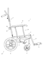
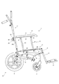
本発明にかかるリクライニング可能な車椅子の手摺りの一実施例を図面に基づいて説明する。第1図は本発明にかかる手摺りを備えた車椅子を示す全体側面図である。第2図はその側断面図である。第3図はそのリクライニング状態を示す側断面図である。第4図は係止手段を示す説明図である。第5図は係止手段の動作する様子を示す説明図である。第6図はリクライニングに追従して手摺りが動作する様子を示す側面図である。第7図は手摺りが単独で動作する様子を示す側面図である。第8図は手摺りの車椅子への特別な枢結状態を示す模式図である。なお、車椅子に利用者が座っている状態の利用者の向きを基準として、前後左右とする。 An embodiment of a handrail for a reclining wheelchair according to the present invention will be described with reference to the drawings. FIG. 1 is an overall side view showing a wheelchair provided with a handrail according to the present invention. FIG. 2 is a side sectional view thereof. FIG. 3 is a side sectional view showing the reclining state. FIG. 4 is an explanatory view showing the locking means. FIG. 5 is an explanatory view showing how the locking means operates. FIG. 6 is a side view showing a state in which the handrail operates following the reclining. FIG. 7 is a side view showing a state in which the handrail operates independently. FIG. 8 is a schematic diagram showing a special pivoting state of a handrail to a wheelchair. In addition, it is set as front and rear, right and left on the basis of the direction of the user who is sitting on the wheelchair.
まず、本発明にかかる手摺り1,1を具備させるリクライニング可能な車椅子Wの一例を説明する。
この車椅子Wは、第2図に示すように、車体フレーム2を備えている。この車体フレーム2の前下部には左右一対のキャスター3,3が軸着されており、後下部には左右一対の転動自在な後輪4,4が取付けられている。この車体フレーム2の上部かつ前後方向略々中間部には腰受フレーム5が揺動自在に枢着されている。さらに、この腰受フレーム5後端部には背凭れフレーム6が上下回動自在に枢結されている。なお、この背凭れフレーム6は、下端部が車体フレーム2に枢着されたリンクフレーム7の前後回動自在に構成した上端部に枢結され、さらに背凭れフレーム6と腰受フレーム5の下方位置において車体フレーム2と背凭れフレーム6は伸縮杆8にて連結されている。また、前記腰受フレーム5前端部には脚受フレーム9が上下回動自在に枢着され、この脚受フレーム9と車体フレーム2間に伸縮杆10が取付けられるとともに、脚受フレーム9下端部にはステップ11,11が取付けられている。なお、図示してはいないが、前記背凭れフレーム6と腰受フレーム5及び脚受フレーム9には背受マット、腰受マット、脚受マットが配設される。
First, an example of a reclining wheelchair W provided with the
The wheelchair W includes a
上述のように構成されたリクライニング可能な車椅子Wは、第3図に示すように、伸縮杆8をレバー(図示省略)の操作により伸縮可能な状態とし、伸縮杆8を縮めると背凭れフレーム6は腰受フレーム5との枢着部を中心として後方回動する。このとき、リンクフレーム7が前方回動するので背凭れフレーム6は前下方へ引き込まれながら後傾され、これに連動するように腰受フレーム5は前方部が上昇されて、利用者の前方へのズレを防止する状態でのリクライニングが可能となっている。
また、別のレバー(図示省略)の操作により伸縮杆10を伸縮可能な状態とし、脚受フレーム9を任意の位置に上方回動することも可能である。
As shown in FIG. 3, the reclining wheelchair W configured as described above makes the telescopic rod 8 extendable by operating a lever (not shown), and when the telescopic rod 8 is contracted, the
It is also possible to make the
続いて、上述のようなリクライニング可能な車椅子Wに具備される本発明にかかる手摺り1,1について説明する。なお、当該手摺り1,1は平面視において車椅子Wの両側部に一対構成されるが、以降一方の手摺り1についてのみ説明をする。
この手摺り1は、アームレスト12と、アームレスト12を腰受フレーム5側部上方で支持する支持リンク13と、アームレスト12後部を背凭れフレーム6側部に係止するための係止手段14から構成されている。
Subsequently, the
The
前記アームレスト12は、第2図に示すように、フレームパイプ15の前下面と中間部後方寄りの下面に軸受部材16,16がそれぞれ固着され、フレームパイプ15上面にクッション部材17が配設されている。また、このアームレスト12のフレームパイプ15後端部には前記係止手段14が備えられている。
前記係止手段14は、第4図に示すように、前記フレームパイプ15後端部に固着された大径部と小径部とからなる段付き空孔部18aが穿たれた軸受筒18の大径部にバネ等の弾性体19が装填され、大軸部20aと小軸部20bとからなる係止部材20の小軸部20bが前記弾性体19に挿通されるとともに、前記軸受筒18の段付き空孔部18aの小径部に挿通され、係止部材20の小軸部20bの一端部にグリップ部材21が止着されている。すなわち、この係止手段14は、第4図の(b)図に示すようにグリップ部材21を引くことで前記軸受筒18より突出している係止部材20の大軸部20aを軸受筒18内部に収納できるようにされており、また、グリップ部材21を引くことをやめると、第4図の(a)図に示すように、弾性体19の付勢力にて係止部材20の大軸部20aが軸受筒18から突出した状態に戻るようにされている。
次に、前記支持リンク13は、第2図に示すように、腰受フレーム5に固着されている軸受部材22,22に、杆体23,23の下端部がそれぞれ枢結されるとともに、杆体23,23の上端部がそれぞれ前記アームレスト12の軸受部材16,16に枢結され、四節リンクを形成している。
As shown in FIG. 2, the
As shown in FIG. 4, the locking means 14 has a
Next, as shown in FIG. 2, the
このように構成された手摺り1は、第2図及び第3図に示すように、背凭れフレーム6に固着されている係止プレート24の前記係止手段14の係止部材20が係止可能かつ摺動可能な長穴24aに、第4図の(a)図に示すように係止部材20の大軸部20aが挿通された状態において、手摺りとしての機能を果たすようにされている。
As shown in FIGS. 2 and 3, the
次に、車椅子Wのリクライニングに追従して手摺り1が動作する様子を説明する。
まず、第1図に示す車椅子Wの状態からリクライニングさせると、第4図の(a)図と第5図の(c)図に示すように、前記係止手段14の係止部材20が背凭れフレーム6の係止プレート24の長穴24aに挿通されていることで手摺り1は背凭れフレーム6に係止されており、背凭れフレーム6の後方回動に追従してアームレスト12は後方へ引っ張られるようになる。アームレスト12が後方へ引っ張られると、支持リンク13が腰受フレーム5に対して後方へ回動されるようになる。なお、係止手段14の係止部材20は背凭れフレーム6の係止プレート24の長穴24aに弾性体19の付勢力にて外れることがないよう挿通されているだけなので、係止部材20を中心にアームレスト12が背凭れフレーム6に対して回動可能であるとともに、係止部材20は係止プレート24の長穴24aに沿って摺動可能である。よって、アームレスト12と支持リンク13と腰受フレーム5が平行リンクを形成していない場合や、背凭れフレーム6の回動中心の位置が腰受フレーム5と支持リンク13との枢結部を含む直線上に常に位置しない場合、または、背凭れフレーム6とアームレスト12が係止手段14にて係止される位置がアームレスト12と支持リンク13との枢結部を含む直線上に常に位置しない場合等においても、車椅子Wのリクライニング動作時に係止手段14の係止部材20がアームレスト12と支持リンク13の枢結部との位置関係を常に一定に保つよう背凭れフレーム6の係止プレート24の長穴24aを摺動できるとともに、係止部材20を中心にアームレスト12が背凭れフレーム6に対して回動でき、背凭れフレーム6のリクライニングに支持リンク13によるアームレスト12の回動を追従させることができる。したがって、背凭れフレーム6のリクライニングに追従して、第6図に示すように、アームレスト12は支持リンク13にて後方へ回動され、車椅子Wのリクライニングに追従して手摺り1が移動される。
また、車椅子Wのリクライニングを復帰させると、その動作に追従して第6図に示す手摺り1の動作軌跡を逆にたどるように手摺り1は元の状態へ戻される。
Next, a state in which the
First, when reclining from the state of the wheelchair W shown in FIG. 1, as shown in FIGS. 4 (a) and 5 (c), the locking
Further, when the reclining of the wheelchair W is returned, the
このように、この手摺り1は係止手段14の係止部材20を背凭れフレーム6の係止プレート24に、車椅子Wのリクライニング動作時に係止部材20を中心にアームレスト12が背凭れフレーム6に対して回動可能かつ係止部材20が係止プレート24の長穴24aに沿って摺動可能に係止させるようにした。これによると、アームレスト12と支持リンク13と腰受フレーム5が平行リンクを形成していない場合や、背凭れフレーム6の回動中心の位置が腰受フレーム5と支持リンク13との枢結部を含む直線上に常に位置しない場合、または、背凭れフレーム6とアームレスト12が係止手段14にて係止される位置がアームレスト12と支持リンク13との枢結部を含む直線上に常に位置しない場合等においても、手摺り1を車椅子Wのリクライニングに追従して移動させることができ、車椅子Wをリクライニングさせた際にも車椅子W側部からの利用者の転落を防止することができる。
また、手摺り1を車椅子Wのリクライニングに追従して動作するようにしたことで、車椅子Wが第1図に示す状態において車椅子W側部からの利用者の転落を防止できる大きさの手摺り1で、リクライニング状態においても車椅子W側部からの利用者の転落を防止することができ、車椅子Wを全体としてコンパクトに構成することができる。さらに、アームレスト12に利用者の腕を乗せた状態でも利用者に違和感を与えることなくリクライニングをさせることができる。
In this way, the
Moreover, the handrail of the magnitude | size which can prevent the fall of the user from the wheelchair W side part in the state which the wheelchair W shows in FIG. 1 by having operated the
なお、次の条件を満たすように本発明にかかる手摺りを構成すると、車椅子のリクライニング動作時にアームレストに具備した係止手段を背凭れフレームに沿って摺動させる必要がなくなる。この条件について第8図を用いて説明する。
一つ目の条件として、上記背凭れフレーム6に当たる部材25の回動中心26と上記支持リンクに当たる部材27,27の上記腰受フレーム5に当たる部材28への枢結部29,30が側面視において同一直線上に位置するようにする。
二つ目の条件として、部材27,27と上記アームレスト12に当たる部材31を枢結部32,33にて枢結する。このとき、枢結部32,33間の距離と枢結部29,30間の距離を等しくし、部材27,27と部材28と部材31にて平行リンクを形成させる。
三つ目の条件として、部材25と部材28の上記係止手段14による係止位置34を、側面視において枢結部32,33を結ぶ直線上かつ枢結部32,33に対する係止位置34の距離が枢結部29,30に対する回動中心26の距離と等しくする。
If the handrail according to the present invention is configured to satisfy the following conditions, it is not necessary to slide the locking means provided on the armrest along the backrest frame during the reclining operation of the wheelchair. This condition will be described with reference to FIG.
The first condition is that the
As a second condition, the
As a third condition, the locking
このようにしておくと、第8図の(b)図に示すように、部材25をリクライニングさせた際に、部材25の回動量に対して部材27,27の回動量が等しくなるとともに、部材28と部材31は常に平行となるため、部材25に対する係止位置34の位置は常に一定となって、部材25のリクライニングに部材27,27による部材28の回動が追従する。
したがって、車椅子のリクライニング動作時に背凭れフレームの回動中心の位置が常に一定な車椅子に上記条件を満たす手摺り具備させる場合には、車椅子のリクライニング動作時にアームレストを背凭れフレームに対して回動可能となるよう係止手段にてアームレストを背凭れフレームに係止させておくだけで、背凭れフレームのリクライニングに支持リンクによるアームレストの回動を追従させることができるようになり、係止手段の係止部材を背凭れフレームに沿って摺動させる必要がなくなる。また、車椅子のリクライニング動作時に背凭れフレームの回動中心の位置が変化する車椅子でも、第8図に示す回動中心26と枢結部29,30が常に一直線上に位置するように、腰受フレームが回動する車椅子であれば、上記条件を満たす手摺りを具備させた際に、係止手段の係止部材を背凭れフレームに沿って摺動させなくても、手摺りを車椅子のリクライニングに追従して移動させることができる。
また、上述の条件を満たしていなくても、上記手摺り1の支持リンク13の杆体23,23を一つとすれば、車椅子Wのリクライニング動作時にアームレストを背凭れフレームに対して回動可能となるよう係止手段にてアームレストを背凭れフレームに係止させておくだけで、車椅子Wのリクライニングに追従して手摺りを移動させることができ、係止手段の係止部材を背凭れフレームに沿って摺動させる必要がなくなる。
In this way, as shown in FIG. 8 (b), when the
Therefore, when a handrail satisfying the above conditions is provided in a wheelchair where the position of the center of rotation of the backrest frame is always constant during the reclining operation of the wheelchair, the armrest can be rotated with respect to the backrest frame during the reclining operation of the wheelchair. Just by locking the armrest to the backrest frame with the locking means, the rotation of the armrest by the support link can follow the reclining of the backrest frame. It is not necessary to slide the stop member along the backrest frame. Further, even in a wheelchair in which the position of the center of rotation of the backrest frame changes during the reclining operation of the wheelchair, the hip rest and the
Even if the above-described conditions are not satisfied, the armrest can be rotated with respect to the backrest frame during the reclining operation of the wheelchair W by using one
続いて、手摺り1が車椅子Wのリクライニングに関係なく単独で動作する様子を説明する。
まず、第4図の(a)図の状態にある係止手段14の係止部材20を、弾性体19の付勢力に逆らってグリップ部材21を引くことで、第4図の(b)図に示すように背凭れフレーム6の係止プレート24の長穴24aから引き抜く。すると、背凭れフレーム6に対しての手摺り1の係止が解除され、支持リンク13にてアームレスト12が回動可能な状態となる。そして、手摺り1を後方へ移動させると第7図に示すように、車椅子W側部を開放することができる。
また、元に戻す際には、アームレスト12を前方へ移動させるようにすると、第7図に示す車椅子W側部を開放したときと同じ軌跡を逆にたどりながら、支持リンク13にてアームレスト12は前方へ回動される。そして、第5図の(a)図の状態となる。さらにアームレスト12を前方へ移動させると、係止手段14の係止部材20が背凭れフレーム6の係止プレート24に接触するとともに、係止プレート24に接触しながら係止部材20が移動されるようになり、第5図の(b)図に示すように係止部材20が軸受筒18に徐々に収納される。そして、さらにアームレスト12が前方へ移動されると、第5図の(c)図に示すように係止手段14の弾性体19の付勢力にて背凭れフレーム6の係止プレート24の長穴24aに係止手段14の係止部材20が挿通され、手摺り1は背凭れフレーム6に係止される。すなわち、手摺り1を元に戻す際には、アームレスト12を前方へ移動させるだけで良い。
なお、車椅子Wをリクライニングさせた状態でも、上述と同じ手順を踏むことで、手摺り1を後方へ移動させて車椅子W側部を開放でき、また、手摺り1を元の状態へ戻すことができる。
Next, a state in which the
First, by pulling the
Further, when the
Even when the wheelchair W is reclined, the
このように、この手摺り1は係止手段14と背凭れフレーム6の係止プレート24との係止を解除可能としたことで、手摺り1を単独で後方へ移動させて車椅子W側部を開放でき、車椅子W側部からベッド等への移乗を至便に行うことができる。
また、この手摺り1はアームレスト12を支持リンク13にて支持していることで、手摺り1と背凭れフレーム6との係止を解除した場合においても、アームレスト12を移動させる際に所定の動作軌跡で移動させることができる。特に、車椅子W側部を開放した状態から手摺りとして機能を果たす状態へ手摺り1を戻す際に、アームレスト12を前方へ移動させるだけの簡便な操作で、係止手段14を係止プレート24に係止できる位置へ移動させることができる。
さらに、この手摺り1は係止手段14の係止部材20を軸受筒18に収納可能かつ弾性体19の付勢力にて軸受筒18から突出するよう構成していることで、上述したように、アームレスト12を移動させるだけで係止手段14の係止部材20を背凭れフレーム6の係止プレート24の長穴24aに係止させることができ、簡便な操作で手摺り1を背凭れフレーム6に係止させることができる。
In this way, the
Further, since the
Further, the
なお、本実施例においては支持リンク13を四節リンクとなるように構成しているが、図示してはいないが、アームレストに所望する動作をさせる支持リンクとするとともに、係止手段の係止部材がアームレストと支持リンクの枢結部との位置関係を常に一定に保つよう摺動できるように背凭れフレームの係止プレートに長穴を設けると、車椅子Wのリクライニングに追従して所望の動作軌跡で手摺りを動作させることができるようになる。
また、本実施例の支持リンク13はアームレスト12と腰受フレーム5との間に構成しているが、図示していないが、支持リンク13をアームレスト12と車体フレーム2との間に構成するようにしても、上述と同様の作用と効果を得ることができる。
さらに、本実施例の背凭れフレーム6の係止プレート24には長穴24aを設けているが、図示してはいないが、長穴24aの代わりに溝部としても上述と同様の作用と効果を得ることができる。
In this embodiment, the
Further, although the
Furthermore, although the
続いて、実施例2として別の係止手段を用いた手摺りを図面に基づいて説明する。第9図は別の係止手段を示す説明図である。なお、実施例1における部材と共通する部材については同一符号を付記する。また、当該手摺りは平面視において車椅子Wの両側部に一対構成されるが、以降一方の手摺りについてのみ説明をする。
この手摺り35は、上記アームレスト12と、アームレスト12を上記腰受フレーム5側部上方で支持する上記支持リンク13と、アームレスト12後部を上記背凭れフレーム6側部に係止するための係止手段36から構成されており、上記手摺り1と異なる点は係止手段36のみである。
Then, the handrail using another latching means is demonstrated as Example 2 based on drawing. FIG. 9 is an explanatory view showing another locking means. In addition, the same code | symbol is attached about the member which is common in the member in Example 1. FIG. Moreover, although the said handrail is comprised in a pair by the both sides of the wheelchair W in planar view, only one handrail is demonstrated hereafter.
The
この係止手段36は、第9図に示すように、上記アームレスト12のフレームパイプ15後端部に雌ネジ部37aが備えられた軸受筒37が固着され、この雌ネジ部37aにネジ部38aを備えた係止部材38が止着されている。
この係止手段36を備えた手摺り35は、第9図の(b)図に示すように、上記背凭れフレーム6に固着されている係止プレート39の前記係止手段36の係止部材38が係止可能かつ摺動可能な長穴39aに係止部材38を挿通させるように係止手段36の軸受筒37に係止部材38をねじ込んだ状態において、手摺りとしての機能を果たすようにされている。
As shown in FIG. 9, the locking means 36 has a
As shown in FIG. 9B, the
このように手摺り35の係止手段36を構成しても、係止手段36の軸受筒37への係止部材38のねじ込み量を変えることで、背凭れフレーム6と手摺り35との係止または係止解除を行うことができる。したがって、この手摺り35も、背凭れフレーム6と手摺り35の係止を解除し、支持リンク13にてアームレスト12を回動させることで車椅子W側部を開放することができる。
また、背凭れフレーム6に手摺り35を係止した状態においては、係止手段36の係止部材38は背凭れフレーム6の係止プレート39の長穴39aに挿通されているだけなので、係止部材38は係止プレート39の長穴39aに沿って摺動可能であるとともに、アームレスト12は係止部材38を中心に背凭れフレーム6に対して回動可能である。したがって、車椅子Wがリクライニングされると、前記係止手段36の係止部材38がアームレスト12と支持リンク13の枢結部との位置関係を常に一定に保つように係止プレート39の長穴39aを摺動するとともに、係止部材38を中心に背凭れフレーム6に対してアームレスト12が回動し、背凭れフレーム6のリクライニングに支持リンク13によるアームレスト12の回動が追従され、この手摺り35も車椅子Wのリクライニングに追従して移動させることができる。
Even if the locking means 36 of the
Further, in the state where the
続いて、実施例3として別の形態の手摺りについて説明する。第10図は係止手段を背凭れフレームに具備した場合の手摺りを示す説明図である。なお、実施例1における部材と共通する部材については同一符号を付記する。また、当該手摺りは平面視において車椅子Wの両側部に一対構成されるが、以降一方の手摺りについてのみ説明をする。
この手摺り40は、上記アームレスト12と、アームレスト12を上記腰受フレーム5側部上方で支持する上記支持リンク13と、アームレスト12後部を上記背凭れフレーム6側部に係止するための係止プレート41から構成されている。すなわち、上記手摺り1と異なる点は係止手段14の代わりに係止プレート41が備えられている点である。
Next, another form of handrail will be described as Example 3. FIG. 10 is an explanatory view showing a handrail when the locking means is provided on the back frame. In addition, the same code | symbol is attached about the member which is common in the member in Example 1. FIG. Moreover, although the said handrail is comprised in a pair by the both sides of the wheelchair W in planar view, only one handrail is demonstrated hereafter.
The
この係止プレート41は、第10図に示すように、上記アームレスト12のフレームパイプ15後端部に固着されており、上記係止手段14の係止部材20が係止可能かつ摺動可能な長穴41aが穿たれている。
この係止プレート41を備えた手摺り40は、第10図の(a)図に示すように、上記背凭れフレーム6に備えられている上記係止手段14の係止部材20がアームレスト12の係止プレート41の長穴41aに挿通された状態において、手摺りとしての機能を果たすようにされている。
As shown in FIG. 10, the locking
As shown in FIG. 10 (a), the
この手摺り40は背凭れフレーム6に備えた係止手段14のグリップ部材21を、第10図の(c)図に示すように引くことで、アームレスト12の係止プレート41の長穴41aから係止手段14の係止部材20を引き抜くことができ、手摺り40の背凭れフレーム6に対する係止を解除することができる。したがって、この手摺り40も、背凭れフレーム6と手摺り40の係止を解除し、支持リンク13にてアームレスト12を回動させることで車椅子W側部を開放することができる。また、手摺り40を元に戻す際には、アームレスト12を元に戻す方向へ支持リンク13にて回動させると、アームレスト12の係止プレート41と背凭れフレーム6の係止手段14の係止部材20が接触するとともに、係止プレート41が係止部材20に接触しながら移動するようになり、第10図の(b)に示すように係止部材20が軸受筒18に徐々に収納される。そして、さらにアームレスト12が移動されると、第10図の(a)図に示すように係止手段14の弾性体19の付勢力にて係止部材20が突出し、アームレスト12の係止プレート41の長穴41aに挿通され、手摺り40は背凭れフレーム6に係止される。すなわち、手摺り40を元に戻す際には、アームレスト12を元に戻す方向へ移動させるだけで良い。
The
また、背凭れフレーム6に手摺り40を係止した状態においては、第10図の(a)図に示すように、背凭れフレーム6の係止手段14の係止部材20はアームレスト12の係止プレート41の長穴41aに弾性体19の付勢力にて外れることがないよう挿通されているだけなので、係止部材20は係止プレート41の長穴41aに沿って摺動可能であるとともに、アームレスト12は係止部材20を中心に背凭れフレーム6に対して回動可能である。したがって、車椅子Wがリクライニングされると、背凭れフレーム6の係止手段14の係止部材20がアームレスト12と支持リンク13との枢結部との位置関係を常に一定に保つようにアームレスト12の係止プレート41の長穴41aを摺動するとともに、係止部材20を中心に背凭れフレーム6に対してアームレスト12が回動し、背凭れフレーム6のリクライニングに支持リンク13によるアームレスト12の回動が追従され、この手摺り40も車椅子Wのリクライニングに追従して移動させることができる。
したがって、この手摺り40によっても、実施例1の手摺り1と同様の作用と効果を得ることができる。
Further, in the state where the
Therefore, the
すなわち、本発明にかかる手摺りの係止手段は、背凭れフレームと手摺りとの係止状態を任意に係止または係止解除可能であるとともに、車椅子のリクライニング動作時に係止手段を中心にアームレストが背凭れフレームに対して回動可能に係止できるものであれば良い。
また、アームレストと支持リンクと車椅子が平行リンクを形成していない場合や、背凭れフレームの回動中心の位置が車椅子と支持リンクとの枢結部を含む直線上に常に位置しない場合、または、背凭れフレームとアームレストが係止手段にて係止される位置がアームレストと支持リンクとの枢結部を含む直線上に常に位置しない場合等において本発明にかかる手摺りを用いる場合には、上述の係止手段が背凭れフレームと手摺りを係止した状態で、背凭れフレームのリクライニングに追従して支持リンクにてアームレストが回動できるように、背凭れフレームとアームレストが係止手段にて係止される位置とアームレストと支持リンクの枢結部との位置関係を常に一定に保つよう係止手段が背凭れフレームまたはアームレストに沿って摺動できるようにすれば良い。
That is, the handrail locking means according to the present invention can arbitrarily lock or release the locking state of the backrest frame and the handrail, and is centered on the locking means during the reclining operation of the wheelchair. Any armrest can be used as long as it can be pivotably locked to the backrest frame.
In addition, when the armrest, the support link, and the wheelchair do not form a parallel link, or when the position of the center of rotation of the backrest frame is not always located on the straight line including the pivot part of the wheelchair and the support link, or When the handrail according to the present invention is used in the case where the position where the backrest frame and the armrest are locked by the locking means is not always positioned on the straight line including the pivotal portion of the armrest and the support link, The backrest frame and armrest are locked by the locking means so that the armrest can be rotated by the support link following the reclining of the backrest frame in a state where the backrest frame and the handrail are locked. The locking means slides along the backrest frame or armrest so that the positional relationship between the locked position and the armrest and the pivot of the support link is always kept constant. It is sufficient in order to be able.
1 手摺り
6 背凭れフレーム
12 アームレスト
13 支持リンク
14 係止手段
18 軸受筒
19 弾性体
20 係止部材
35 手摺り
36 係止手段
40 手摺り
W 車椅子
DESCRIPTION OF
Claims (4)
Priority Applications (1)
| Application Number | Priority Date | Filing Date | Title |
|---|---|---|---|
| JP2004149240A JP2005328980A (en) | 2004-05-19 | 2004-05-19 | Reclining handrail for wheelchair |
Applications Claiming Priority (1)
| Application Number | Priority Date | Filing Date | Title |
|---|---|---|---|
| JP2004149240A JP2005328980A (en) | 2004-05-19 | 2004-05-19 | Reclining handrail for wheelchair |
Publications (2)
| Publication Number | Publication Date |
|---|---|
| JP2005328980A true JP2005328980A (en) | 2005-12-02 |
| JP2005328980A5 JP2005328980A5 (en) | 2007-07-05 |
Family
ID=35484003
Family Applications (1)
| Application Number | Title | Priority Date | Filing Date |
|---|---|---|---|
| JP2004149240A Pending JP2005328980A (en) | 2004-05-19 | 2004-05-19 | Reclining handrail for wheelchair |
Country Status (1)
| Country | Link |
|---|---|
| JP (1) | JP2005328980A (en) |
Cited By (4)
| Publication number | Priority date | Publication date | Assignee | Title |
|---|---|---|---|---|
| JP6221151B1 (en) * | 2017-02-02 | 2017-11-01 | 株式会社土橋製作所 | Care chair |
| CN107485496A (en) * | 2017-09-13 | 2017-12-19 | 广西柳商新能源科技有限公司 | A kind of wheelchair with spare seat |
| JP6273397B1 (en) * | 2017-09-11 | 2018-01-31 | 株式会社土橋製作所 | Care chair |
| JPWO2018163395A1 (en) * | 2017-03-10 | 2020-01-09 | 医療法人和康会 | Training method and training device |
-
2004
- 2004-05-19 JP JP2004149240A patent/JP2005328980A/en active Pending
Cited By (12)
| Publication number | Priority date | Publication date | Assignee | Title |
|---|---|---|---|---|
| JP6221151B1 (en) * | 2017-02-02 | 2017-11-01 | 株式会社土橋製作所 | Care chair |
| JP2018121958A (en) * | 2017-02-02 | 2018-08-09 | 株式会社土橋製作所 | Care chair |
| JPWO2018163395A1 (en) * | 2017-03-10 | 2020-01-09 | 医療法人和康会 | Training method and training device |
| JP7236086B2 (en) | 2017-03-10 | 2023-03-09 | 医療法人和康会 | training equipment |
| JP6273397B1 (en) * | 2017-09-11 | 2018-01-31 | 株式会社土橋製作所 | Care chair |
| WO2019049401A1 (en) * | 2017-09-11 | 2019-03-14 | 株式会社土橋製作所 | Chair for nursing care |
| JP2019047938A (en) * | 2017-09-11 | 2019-03-28 | 株式会社土橋製作所 | Chair for nursing care |
| CN110536669A (en) * | 2017-09-11 | 2019-12-03 | 株式会社土桥制作所 | Nursing chair |
| KR20200045988A (en) | 2017-09-11 | 2020-05-06 | 가부시키가이샤 도바시 세이사쿠쇼 | Nursing chair |
| CN110536669B (en) * | 2017-09-11 | 2021-12-24 | 株式会社土桥制作所 | Chair for nursing |
| KR102401426B1 (en) | 2017-09-11 | 2022-05-23 | 가부시키가이샤 도바시 세이사쿠쇼 | nursing chair |
| CN107485496A (en) * | 2017-09-13 | 2017-12-19 | 广西柳商新能源科技有限公司 | A kind of wheelchair with spare seat |
Similar Documents
| Publication | Publication Date | Title |
|---|---|---|
| US6419260B1 (en) | Wheelchair | |
| JP2003205842A (en) | Stroller with reclining mechanism | |
| JP2008030657A (en) | Vehicle seat device | |
| KR100461102B1 (en) | A reclining device for a rear seat in automobile | |
| JP2007246061A (en) | Child seat | |
| JP2007216948A (en) | Device to fit seat etc. to chassis of baby carriage | |
| JP5237398B2 (en) | Infant transport device having a plurality of sitting postures | |
| JP2005328980A (en) | Reclining handrail for wheelchair | |
| WO2019049401A1 (en) | Chair for nursing care | |
| NL2008763C2 (en) | Child vehicle seat and seat and base suitable for such a child vehicle seat. | |
| CN215652136U (en) | Hand subassembly, lean on and hold up subassembly and wheelchair | |
| JP6397522B2 (en) | Frame structure, wheelchair, stroller & chair | |
| JP5067806B2 (en) | Reclining wheelchair | |
| JP2009126322A (en) | Seat for vehicle | |
| JP4567610B2 (en) | wheelchair | |
| JP3154256U (en) | Chair with table | |
| US20040036335A1 (en) | Nursery chair device with adjustable angle between the seat and a modifiable back and corresponding chair | |
| JP5986154B2 (en) | wheelchair | |
| JP2011131675A (en) | Seat for vehicle | |
| JP3118362U (en) | Adjustable backrest interlocking adjustment structure of the chair | |
| JP2013001176A (en) | Vehicle seat | |
| JP5272723B2 (en) | Vehicle seat | |
| JP3637732B2 (en) | Chair armrest device | |
| JP2009035197A (en) | Vehicular seat | |
| JP4237849B2 (en) | Chair with footrest |
Legal Events
| Date | Code | Title | Description |
|---|---|---|---|
| A521 | Written amendment |
Free format text: JAPANESE INTERMEDIATE CODE: A523 Effective date: 20070517 |
|
| A621 | Written request for application examination |
Free format text: JAPANESE INTERMEDIATE CODE: A621 Effective date: 20070517 |
|
| A977 | Report on retrieval |
Free format text: JAPANESE INTERMEDIATE CODE: A971007 Effective date: 20091112 |
|
| A131 | Notification of reasons for refusal |
Free format text: JAPANESE INTERMEDIATE CODE: A131 Effective date: 20091119 |
|
| A521 | Written amendment |
Free format text: JAPANESE INTERMEDIATE CODE: A523 Effective date: 20100114 |
|
| A02 | Decision of refusal |
Free format text: JAPANESE INTERMEDIATE CODE: A02 Effective date: 20100208 |