JP2009013690A - Parting wall panel for attic space and method of installing the same - Google Patents
Parting wall panel for attic space and method of installing the same Download PDFInfo
- Publication number
- JP2009013690A JP2009013690A JP2007177527A JP2007177527A JP2009013690A JP 2009013690 A JP2009013690 A JP 2009013690A JP 2007177527 A JP2007177527 A JP 2007177527A JP 2007177527 A JP2007177527 A JP 2007177527A JP 2009013690 A JP2009013690 A JP 2009013690A
- Authority
- JP
- Japan
- Prior art keywords
- wall panel
- frame
- opening
- hut
- sides
- Prior art date
- Legal status (The legal status is an assumption and is not a legal conclusion. Google has not performed a legal analysis and makes no representation as to the accuracy of the status listed.)
- Granted
Links
Images


Abstract
Description
本発明は、例えばアパート等の集合住宅の小屋裏空間を住戸間の界壁に沿って間仕切る小屋裏用界壁パネル及びその施工方法に関する。 The present invention relates to a hut back wall panel for partitioning a shed space of an apartment house such as an apartment along a boundary wall between dwelling units, and a construction method thereof.
アパートなどの集合住宅では、隣接する住戸間での延焼を防止するために、各住戸間を間仕切る界壁のみならず、屋根と天井との間の空間である小屋裏空間についても準耐火構造で間仕切ることが法律によって義務付けられている。 In apartment houses such as apartments, in order to prevent the spread of fire between adjacent dwelling units, not only the boundary walls that partition each dwelling unit, but also the hut space that is the space between the roof and the ceiling is semi-fireproof structure It is required by law to partition in.
従来、このような小屋裏空間の間仕切りとして、種々の方法が提案されている。例えば、現場にて小屋裏空間に下地用の木質材からなる束材等を組み立て、その両側面に石膏ボード等の面材を例えば釘打ち等にて貼り付けることにより施工する方法が知られている。しかしながら、このような施工は、高所の限られた狭い作業空間で行われるため、作業効率が悪いという問題がある。 Conventionally, various methods have been proposed for partitioning such a shed space. For example, there is a known method of construction by assembling a bundle of wood materials for the groundwork in the shed space at the site, and attaching a plaster board or other surface material to the both sides of the material with, for example, nailing Yes. However, since such construction is performed in a narrow and narrow work space at a high place, there is a problem that work efficiency is poor.
また、小屋裏用界壁として、鋼製の枠材で予め枠組されたフレーム枠を用い、その両側に面材を添設することも提案されている(下記特許文献1参照)。しかしながら、このものにおいても、現場にて面材をフレーム枠に貼り付けする工程が必要になる。
In addition, it has also been proposed to use a frame frame preliminarily framed with a steel frame material as a hut back boundary wall and attach face materials to both sides thereof (see
本発明は、以上のような実情に鑑み案出なされたもので、フレーム枠と該フレーム枠の両側に添設された面材とを有するパネル構造を有し、しかも面材の下縁の少なくとも一部を前記下枠材に達することなく終端させることにより、面材の下縁と前記下枠材との間に足場板架け渡し用の開口部を設けることを基本として、現場での高所作業、例えば屋根部材との接合作業を能率良く行いうる小屋裏用界壁パネル及びその施工方法を提供することを主たる目的としている。 The present invention has been devised in view of the above circumstances, and has a panel structure having a frame frame and a face material attached to both sides of the frame frame, and at least a lower edge of the face material. By terminating a part without reaching the lower frame material, an opening for spanning the scaffolding plate is provided between the lower edge of the face material and the lower frame material. The main purpose is to provide a hut-back wall panel that can efficiently perform work, for example, joining work with a roof member, and a construction method thereof.
本発明のうち請求項1記載の発明は、最も下方を水平にのびる下枠材を含む複数かつ鋼製の枠材を連結することにより形成されたフレーム枠と、該フレーム枠の両側に予め添設された耐火性を有する面材とを有するパネル構造をなし、しかも前記両側の面材の下縁の少なくとも一部が、前記下枠材に達することなく終端することにより、前記面材の下縁と前記下枠材との間に、前記両側の面材を貫通する足場板架け渡し用の開口部を有することを特徴とする小屋裏用界壁パネルである。
The invention according to
また請求項2記載の発明は、前記開口部は、50〜100mmの高さを有する請求項1記載の小屋裏用界壁パネルである。 According to a second aspect of the present invention, there is provided a hut back boundary wall panel according to the first aspect, wherein the opening has a height of 50 to 100 mm.
また請求項3記載の発明は、前記開口部は、前記下枠材と実質的に等しい長さを有する請求項1又は2記載の小屋裏用界壁パネルである。 According to a third aspect of the present invention, there is provided a hut back boundary wall panel according to the first or second aspect, wherein the opening has a length substantially equal to that of the lower frame member.
また請求項4記載の発明は、請求項1ないし3に記載された小屋裏用界壁パネルを小屋裏空間に配する施工方法であって、一対の小屋裏用界壁パネルを、それらの下部側に設けられた下側金物を住戸を間仕切る向き合う界壁パネル、外壁又は柱に固定することにより、距離を隔てて向き合わせて固定する工程と、前記小屋裏用界壁パネルの向き合う前記開口部に足場板を架け渡す工程と、前記足場板を用いて小屋裏用界壁パネルの上部側に設けられた上側金物を屋根部材に接合する工程と、前記足場板を取り外した後、前記小屋裏用界壁パネルの前記開口部を耐火性を有する面材で閉止する工程とを含むことを特徴とする。
The invention described in
請求項1に係る小屋裏用界壁パネルは、フレーム枠と、該フレーム枠の両側に添設された面材とが予め一体化されたパネル構造をなす。従って、このような界壁パネルを界壁に沿って小屋裏空間に固定することにより、簡単に小屋裏空間の耐火間仕切り構造を施工することが可能になる。
The boundary wall panel for a hut back according to
しかも請求項1に係る小屋裏用界壁パネルは、フレーム枠の最も下方を水平にのびる下枠材と面材の下縁との間に、該面材を貫通する足場板架け渡し用の開口部が設けられている。このため、例えば、該小屋裏用界壁パネルを、小屋裏空間に向き合わせて配することにより、前記開口部に足場板を水平に架け渡しできる。従って、特別な足場などを架設することなく、該足場板を利用して小屋裏内での高所作業、例えば小屋裏用界壁パネルと屋根部材との接合作業などを能率良く接合できる。
In addition, the barrier wall panel for the back of the shed according to
また、請求項5に係る小屋裏用界壁パネルの施工方法では、特別な足場等を架設することなく小屋裏用界壁パネルの開口部間に架け渡された足場板を利用し、該小屋裏用界壁パネルの上部側に設けられた上側金物と屋根部材とを容易に接合できる。また、屋根部材と小屋裏用界壁パネルとの接合の後は、小屋裏用界壁パネルの前記開口部が耐火性の面材で閉止されるので、前記開口部からの延焼を防止できる。 Further, in the construction method of the back wall panel according to claim 5, the scaffold board is used between the openings of the back wall panel without installing a special scaffold or the like. The upper hardware provided on the upper side of the back boundary wall panel and the roof member can be easily joined. In addition, after joining the roof member and the attic wall panel, the opening of the attic wall panel is closed with a fire-resistant face material, so that it is possible to prevent the fire from spreading from the opening.
以下、本発明の実施の一形態を図面に基づき説明する。
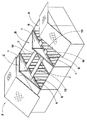
図1には、小屋裏用界壁パネル1の正面図、図2にはそのA−A断面がそれぞれ示される。本実施形態の小屋裏用界壁パネル1は、例えば図3に示されるように、プレハブ式の集合住宅Fの小屋裏空間を、例えば住戸A、B及びCの居室空間を区分する2つの界壁Wiに沿って間仕切る際に好適に利用される。
Hereinafter, an embodiment of the present invention will be described with reference to the drawings.
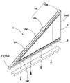
FIG. 1 is a front view of a hut
図1及び図2に示されるように、小屋裏用界壁パネル1は、鋼製の複数の枠材を接合することにより形成されたトラスからなるフレーム枠2と、該フレーム枠2の両側に予め工場等で添設された面材3とを有するパネル構造体として形成される。
As shown in FIG. 1 and FIG. 2, the
本実施形態において、前記フレーム枠2は、直角三角形状に枠組みされた外枠部2Aと、該外枠部2Aの内部を上下にのびる縦桟2Bと、前記外枠部2Aの内部を斜めにのびる斜桟2Cとがそれぞれ接合されて構成される。
In the present embodiment, the
前記外枠部2Aは、最も下方を水平にのびる下枠材2a1と、該下枠材2a1の一端から垂直方向にのびる縦枠材2a2と、前記下枠材2a1の他端と前記縦枠材2a2の上端との間を本実施形態では直線状かつ斜めにのびる上枠材2a3とを含み、かつ、これらを互いに接合することにより直角三角形状に構成される。ここで、「最も下方」とは、該小屋裏用界壁パネル1を使用時の状態に保持したときの「最も下方」の意である。
The
前記各枠材2a1ないし2a3は、例えば溝型鋼からなり、各々の溝部を内側に向けて接合される。同様に、前記縦桟2B及び斜桟2Cも、例えば溝型鋼が採用される。
Each of the frame members 2a1 to 2a3 is made of, for example, groove steel, and is joined with each groove portion facing inward. Similarly, for example, grooved steel is adopted for the
フレーム枠2の輪郭形状は、使用する小屋裏用空間の形状等に基づいて適宜変形できるのは言うまでもない。例えば、図4に示されるように、下枠材2a1と、その両端からそれぞれ垂直方向に異なる高さでのびる縦枠材2a2と、各縦枠材2a2の上端を水平な直線部と傾斜部とを含む折れ曲がり状の上枠材2a3とからなる略五角形状でも良い。また、これ以外にも、矩形状や台形状(ともに図示せず)でも良いのは言うまでもない。
It goes without saying that the contour shape of the
また、図1及び図2に示されるように、本実施形態では、前記フレーム枠2の両側に、木質下地4を介して前記面材3が固着される。該木質下地4は、前記下枠材2a1と平行にのびるとともに該下枠材2a1と重なることなくそれよりも上部の位置をのびる下の下地材4aと、前記縦枠材2a2と平行かつこれと重ねられた縦の下地材4bと、前記上枠材2a3と平行かつこれと重ねられた上の下地材4cとを枠組みしてフレーム枠2と近似した直角三角形状に構成される。なお、木質下地4は、例えば接着及び/又はボルト等によって前記外枠部2Aに固着される。
As shown in FIGS. 1 and 2, in the present embodiment, the
前記面材3は、耐火性を有するものであれば特に限定されることなく種々の材料が採用でき、例えばけい酸カルシウム板、スラグ石膏板、繊維強化セメント板及び/又は繊維混入スラグ石膏系セメントパーライト板などが望ましい。本実施形態の面材3は、内側に配された内の面材3iと、その外側に重ねて配される外の面材3oとを含む2層構造を有する。これらは同一の材料でも良いしまた異なる材料を複合しても良い。また、各面材3i、3oは、適宜小分割された板状片を前記木質下地4に例えば釘n(図2に示す)等によって予め固着される。これにより、木質下地4が囲む三角形状の空間は、前記面材3によって完全に閉じられる。なお、両側の面材3、3で挟まれる空間内には、予めロックウール等の断熱材(図示省略)が充填されるのが望ましい。
The
また、図5に示されるように、小屋裏用界壁パネル1には、各種の金物が予め一体に設けられる。本実施形態において、小屋裏用界壁パネル1には、外枠部2Aの上部側に設けられかつ図3に示される屋根パネルRと接合される上側金物10と、前記外枠部2Aの下部側に設けられかつ前記住宅Fの界壁Wi、外壁Wo及び/又は柱15の上部側に接合される下側金物11とが設けられる。
In addition, as shown in FIG. 5, various hardwares are integrally provided in advance on the hut
前記上側金物10は、本実施形態では、上枠材2a3の最も高い位置に設けられた第1の上側金物10aと、その近傍でかつそれよりも低所に設けられた第2の上側金物10bとを含む。ただし、上側金物10は、3つ以上設けられても良いのは言うまでもない。これらの第1及び第2の上側金物10a及び10bは、上枠材2a3の外面に予め溶着されれた平板状をなすとともに、屋根パネルRと接合するためのボルト(図示省略)が通る複数の孔が形成されている。
In the present embodiment, the
また下側金物11は、本実施形態では、上枠材2a3と下枠材2a1との接合部近傍に設けられた第1の下側金物11aを含む。第1の下側金物11aは、上枠材2a3の外面などに予め溶着されるとともに、複数のボルト孔が設けられた板状で構成される。なお、図示していないが、下枠材2a1の他端側(縦枠材2a2側)には、例えば裏面にナットが溶着されたボルト孔(図示省略)が穿設されるが、これに代えて第2の下側金物(図示省略)が設けられても良い。
In the present embodiment, the
さらに、本実施形態の小屋裏用界壁パネル1は、図1及び図2に示されるように、前記両側の面材3の下縁(最も下の縁)3eの少なくとも一部、本実施形態では全部が、フレーム枠2の下枠材2a1に達することなく終端する。これにより、面材3の下縁3eと下枠材2a1との間に、両側の面材3、3を貫通する足場板架け渡し用の開口部6が形成される。なお、該開口部6を除く他の部分は、実質的に面材3によって全て覆われる。
Further, as shown in FIG. 1 and FIG. 2, the
本実施形態では、面材3の下縁3eから木質下地4が僅かに下方にはみ出して設けられるので、前記開口部6は、実質的に木質下地4の下の下地材4aとフレーム枠2の下枠材2a1との間に形成される。ただし、このような実施形態に限定されるものではない。従って、開口部6は、一定の開口高さhでかつ実質的に下枠材2a1と等しい長さで形成される。ただし、開口部6は、このような態様に限定されるものではなく、開口部6は、下枠材2a1の実質的な全幅をのびることなく、それよりも小さく形成されても良い。
In the present embodiment, the
以上のように構成された本実施形態の小屋裏用界壁パネル1の施工方法の一例について図3に示した流れ屋根を有する前記集合住宅Fを例に挙げて説明する。該住宅Fは、外壁Wo及び居室空間を区切る界壁Wiがいずれも大型パネルPで形成される。なお、図3では、界壁Wiの一部には面材が貼り付けられていない態様が示される。
An example of the construction method of the
本実施形態では、先ず、図3に示されるように、予め外壁Wo及び界壁Wiが建て込まれた構造体に対し、一対の前記小屋裏用界壁パネル1を、それらの下側金物11を住戸を間仕切る向き合う界壁Wi、外壁Wo又は柱15に固定することにより、向き合わせて配する工程が行われる。
In the present embodiment, first, as shown in FIG. 3, a pair of the hut-back
小屋裏用界壁パネル1は、例えば図示しないクレーン等で吊り下げられ又は作業者によって前記家屋内の所定の位置へと搬入される。また、本実施形態では、図5に示されるように、現場において、フレーム枠2の下枠材2a1の下面に木質の下地材12がボルト等によって一体に固着される。そして、図6(a)に示されるように、小屋裏用界壁パネル1の第1の下側金物11aが外壁Woの上端に固定された取付金物J1にボルトを用いて固着される。また、図6(b)に示されるように、小屋裏用界壁パネル1の下枠材2a1の他端側(縦枠材2a2側)は、例えば柱15の上に設けられた柱状金物J2にボルトにて固定される。なお必要により、ブレース等を用いて小屋裏用界壁パネル1の直立状態が保持されても良い。
The hut back
さらに、図7に示されるように、小屋裏用界壁パネル1の下枠材2a1に下面に固着された下地材12は、界壁Wiの上枠材14の上面に載置されかつ釘nによって固定される。このように、小屋裏用界壁パネル1を互いに向き合わせて配することにより、図3に示されるように、小屋裏空間に前記開口部6を同高さでかつ向き合わせて配置できる。
Furthermore, as shown in FIG. 7, the
次に、図8に示されるように、前記小屋裏用界壁パネル1の向き合う前記開口部6に足場板7を架け渡す工程が行われる。即ち、足場板7の両端部をそれぞれ小屋裏用界壁パネル1の開口部6に挿入しかつそれらの下枠材2a1で保持させることにより、足場板7を住戸B内に水平に架け渡しできる。
Next, as shown in FIG. 8, a step of bridging the
足場板7の挿入を容易とするために、小屋裏用界壁パネル1に形成される前記開口部6の開口高さhは、好ましくは50mm以上、より好ましくは60mm以上が望ましい。他方、開口部6の開口高さhが大きすぎると、後に現場にて開口部6を閉止する工程が煩雑化し、生産性を悪化させるおそれがあるので、好ましくは100mm以下に抑えるのが望ましい。なお、開口部6は、作業中における点検窓としても利用しうる点で望ましい。
In order to facilitate the insertion of the
しかる後、前記足場板7上に位置する作業者により、図9に示されるように、小屋裏用界壁パネル1の上側金物10と屋根パネルRとの接合が行われる。即ち、上側金物10と屋根パネルRとの接合が、足場板7の上に位置する作業者によって小屋裏側からかつボルトを用いて行いうる。
Thereafter, as shown in FIG. 9, the operator located on the
屋根パネルRと小屋裏用界壁パネル1との接合作業は、天井の施工に先立ち行われるので、開口部6が無いと、特別な足場の設置や大型の脚立などが必要である。また、従来では、面材3が現場にてトラス枠などに貼り付けられていたため、該トラスなどを足場として作業が行えたが、小屋裏用界壁パネル1のように大部分が予め面材3で覆われているものではこのような作業も行うことができないが、本実施形態では、小屋裏用界壁パネル1を用いつつも小屋裏内での高所作業を能率良く行い得る点で特に望ましい。
Since the joining operation of the roof panel R and the
また本実施形態の開口部6は、小屋裏用界壁パネル1の下枠材2a1と実質的に等しい長さを有するため、2以上の上側金物10a、10bが設けられている場合でも、それに合わせて足場板7の位置を自在に調節することができる。従って、種々の位置で高所作業を能率良く行える。
Moreover, since the
屋根パネルRと小屋裏用界壁パネル1の上側金物10との接合を終えると、前記足場板7が小屋裏用界壁パネル1、1間から取り外される。しかる後、小屋裏用界壁パネル1の前記開口部6を面材で閉塞する工程が行われる。これにより、小屋裏用界壁パネル1の開口部6を経由した延焼などを防止できる。該工程は、種々の方法で行われてもよいが、例えば図10及び図11に示されるように、界壁Wiに添設される耐火性の面材20を用いるのが能率的である。即ち、界壁Wiに添設される面材20の上縁20aを小屋裏用界壁パネル1の面材3の下縁3eまで延在させることにより、工数を増加させることがない。従って、さらに施工性が向上する。なお、図11に示されるように、小屋裏用界壁パネル1と屋根パネルRとの間も高い性の面材21によって閉止される。
When the joining of the roof panel R and the
以上本発明の実施形態について詳述したが、本発明は上記実施形態に限定されることなく本発明の要旨を逸脱しない範囲において種々の態様に変更して実施しうるのは言うまでもない。 Although the embodiment of the present invention has been described in detail above, it is needless to say that the present invention is not limited to the above-described embodiment and can be implemented in various forms without departing from the gist of the present invention.
1 小屋裏用界壁パネル
2 フレーム枠
2a1 下枠材
2b3 上枠材
3 面材
3e 面材の下縁
6 足場板架け渡し用の開口部
7 足場板
DESCRIPTION OF
Claims (4)
前記両側の面材の下縁の少なくとも一部が、前記下枠材に達することなく終端することにより、前記面材の下縁と前記下枠材との間に、前記両側の面材を貫通する足場板架け渡し用の開口部を有することを特徴とする小屋裏用界壁パネル。 It has a frame frame formed by connecting a plurality of steel frame members including a lower frame member that extends horizontally at the bottom, and a fire-resistant face material previously attached to both sides of the frame frame. By forming a panel structure, and at least a part of the lower edge of the face material on both sides terminates without reaching the lower frame material, the lower edge material of the face material and the lower frame material, A barrier wall panel for a back of a hut having an opening for passing a scaffold board penetrating through face materials on both sides.
一対の小屋裏用界壁パネルを、それらの下部側に設けられた下側金物を住戸を間仕切る向き合う界壁パネル、外壁又は柱に固定することにより、距離を隔てて向き合わせて固定する工程と、
前記小屋裏用界壁パネルの向き合う前記開口部に足場板を架け渡す工程と、
前記足場板を用いて小屋裏用界壁パネルの上部側に設けられた上側金物を屋根部材に接合する工程と、
前記足場板を取り外した後、前記小屋裏用界壁パネルの前記開口部を耐火性を有する面材で閉止する工程とを含むことを特徴とする小屋裏用界壁パネルの施工方法。 A construction method for arranging the attic space wall panel according to claim 1 in the attic space,
A process of fixing a pair of shed back wall panels facing each other at a distance by fixing lower metal fittings provided on the lower side thereof to facing wall panels, outer walls, or pillars that partition a dwelling unit. When,
Spanning a scaffolding plate to the opening facing the hut back wall panel;
Joining the upper hardware provided on the upper side of the barrier wall panel for the hut using the scaffolding plate to the roof member;
And a step of closing the opening of the back wall panel with a face material having fire resistance after removing the scaffold plate.
Priority Applications (1)
| Application Number | Priority Date | Filing Date | Title |
|---|---|---|---|
| JP2007177527A JP5180527B2 (en) | 2007-07-05 | 2007-07-05 | Construction method of the back wall panel |
Applications Claiming Priority (1)
| Application Number | Priority Date | Filing Date | Title |
|---|---|---|---|
| JP2007177527A JP5180527B2 (en) | 2007-07-05 | 2007-07-05 | Construction method of the back wall panel |
Publications (2)
| Publication Number | Publication Date |
|---|---|
| JP2009013690A true JP2009013690A (en) | 2009-01-22 |
| JP5180527B2 JP5180527B2 (en) | 2013-04-10 |
Family
ID=40354915
Family Applications (1)
| Application Number | Title | Priority Date | Filing Date |
|---|---|---|---|
| JP2007177527A Active JP5180527B2 (en) | 2007-07-05 | 2007-07-05 | Construction method of the back wall panel |
Country Status (1)
| Country | Link |
|---|---|
| JP (1) | JP5180527B2 (en) |
Cited By (4)
| Publication number | Priority date | Publication date | Assignee | Title |
|---|---|---|---|---|
| JP2011231491A (en) * | 2010-04-26 | 2011-11-17 | Daiwa House Industry Co Ltd | Attic space parting wall and attic space parting wall construction method |
| JP2013076299A (en) * | 2011-09-30 | 2013-04-25 | Musashi Seiko Co Ltd | Semispherical construction, construction method thereof and triangular structure |
| CN107012975A (en) * | 2017-03-15 | 2017-08-04 | 浙江水利水电学院 | The water-retaining structure and construction method of a kind of ancient building shelter bridge |
| GB2595688A (en) * | 2020-06-03 | 2021-12-08 | Marley Ltd | Intumescent fire barrier |
Citations (6)
| Publication number | Priority date | Publication date | Assignee | Title |
|---|---|---|---|---|
| JPS6132402U (en) * | 1984-07-31 | 1986-02-27 | 住友軽金属工業株式会社 | simple building |
| JPH06306998A (en) * | 1993-04-26 | 1994-11-01 | Sekisui Chem Co Ltd | Unit roof with separation wall |
| JPH06322882A (en) * | 1993-05-11 | 1994-11-22 | Sekisui Chem Co Ltd | Roof unit |
| JPH1130029A (en) * | 1997-07-10 | 1999-02-02 | Sekisui Chem Co Ltd | Scaffold |
| JPH11343694A (en) * | 1998-05-29 | 1999-12-14 | National House Ind Co Ltd | Structure of garret |
| JP2000192597A (en) * | 1998-12-24 | 2000-07-11 | Sekisui House Ltd | Principal rafter part installing metal fitting of boundary wall stud frame in boundary wall part of attic space |
-
2007
- 2007-07-05 JP JP2007177527A patent/JP5180527B2/en active Active
Patent Citations (6)
| Publication number | Priority date | Publication date | Assignee | Title |
|---|---|---|---|---|
| JPS6132402U (en) * | 1984-07-31 | 1986-02-27 | 住友軽金属工業株式会社 | simple building |
| JPH06306998A (en) * | 1993-04-26 | 1994-11-01 | Sekisui Chem Co Ltd | Unit roof with separation wall |
| JPH06322882A (en) * | 1993-05-11 | 1994-11-22 | Sekisui Chem Co Ltd | Roof unit |
| JPH1130029A (en) * | 1997-07-10 | 1999-02-02 | Sekisui Chem Co Ltd | Scaffold |
| JPH11343694A (en) * | 1998-05-29 | 1999-12-14 | National House Ind Co Ltd | Structure of garret |
| JP2000192597A (en) * | 1998-12-24 | 2000-07-11 | Sekisui House Ltd | Principal rafter part installing metal fitting of boundary wall stud frame in boundary wall part of attic space |
Cited By (5)
| Publication number | Priority date | Publication date | Assignee | Title |
|---|---|---|---|---|
| JP2011231491A (en) * | 2010-04-26 | 2011-11-17 | Daiwa House Industry Co Ltd | Attic space parting wall and attic space parting wall construction method |
| JP2013076299A (en) * | 2011-09-30 | 2013-04-25 | Musashi Seiko Co Ltd | Semispherical construction, construction method thereof and triangular structure |
| CN107012975A (en) * | 2017-03-15 | 2017-08-04 | 浙江水利水电学院 | The water-retaining structure and construction method of a kind of ancient building shelter bridge |
| CN107012975B (en) * | 2017-03-15 | 2019-04-09 | 浙江水利水电学院 | A kind of water-retaining structure and construction method of ancient building shelter bridge |
| GB2595688A (en) * | 2020-06-03 | 2021-12-08 | Marley Ltd | Intumescent fire barrier |
Also Published As
| Publication number | Publication date |
|---|---|
| JP5180527B2 (en) | 2013-04-10 |
Similar Documents
| Publication | Publication Date | Title |
|---|---|---|
| US20100058687A1 (en) | Method of constructing a multi-storey building using prefabricated modular panels | |
| JP2019509415A (en) | Multi-storey building construction method using stacked structural steel wall trusses. | |
| JP5647747B1 (en) | Wall panel joining method | |
| US20080148678A1 (en) | Frames For Buildings | |
| US11384550B2 (en) | Pre-fabricated skeletal frame for a room | |
| JP5180527B2 (en) | Construction method of the back wall panel | |
| JP5714161B1 (en) | Wall panel joining structure and wall panel joining method | |
| JP7351731B2 (en) | Overhang panel unit construction method and overhang panel structure | |
| JP2006322205A (en) | Wall type wooden building | |
| JP3599240B2 (en) | External wall forming method and metal fittings used in external insulation building of reinforced concrete wall type structure | |
| CA2639339A1 (en) | Method of constructing a multi-storey building using prefabricated modular panels | |
| JP2003049484A (en) | Construction method for wooden house | |
| JP6444094B2 (en) | Architectural panel joint structure and building | |
| KR100414594B1 (en) | Block for a Steel House and The Constructing Method | |
| JP7310502B2 (en) | Opening construction method | |
| JP4381537B2 (en) | Unit type building and its assembling method | |
| JP6532391B2 (en) | Construction method of aseismic reinforcing wall | |
| JP4018000B2 (en) | Construction method of unit type building | |
| JP6992971B2 (en) | Detachable extension room | |
| JP2009215750A (en) | Chamber unit reinforcing structure of wooden house | |
| JP2023080578A (en) | wall panel | |
| JPH0734538A (en) | Wooden building | |
| RU2198988C2 (en) | Process of erection of monolithic walls of buildings and structures in permanent forms | |
| JP3701707B2 (en) | Ceiling structure of building unit | |
| JP2015218461A (en) | Fire-resisting frame structure |
Legal Events
| Date | Code | Title | Description |
|---|---|---|---|
| A621 | Written request for application examination |
Free format text: JAPANESE INTERMEDIATE CODE: A621 Effective date: 20100323 |
|
| A131 | Notification of reasons for refusal |
Free format text: JAPANESE INTERMEDIATE CODE: A131 Effective date: 20120501 |
|
| A521 | Written amendment |
Free format text: JAPANESE INTERMEDIATE CODE: A523 Effective date: 20120621 |
|
| TRDD | Decision of grant or rejection written | ||
| A01 | Written decision to grant a patent or to grant a registration (utility model) |
Free format text: JAPANESE INTERMEDIATE CODE: A01 Effective date: 20121225 |
|
| A61 | First payment of annual fees (during grant procedure) |
Free format text: JAPANESE INTERMEDIATE CODE: A61 Effective date: 20130111 |
|
| R150 | Certificate of patent or registration of utility model |
Ref document number: 5180527 Country of ref document: JP Free format text: JAPANESE INTERMEDIATE CODE: R150 |
|
| R250 | Receipt of annual fees |
Free format text: JAPANESE INTERMEDIATE CODE: R250 |
|
| R250 | Receipt of annual fees |
Free format text: JAPANESE INTERMEDIATE CODE: R250 |
|
| S533 | Written request for registration of change of name |
Free format text: JAPANESE INTERMEDIATE CODE: R313533 |
|
| R350 | Written notification of registration of transfer |
Free format text: JAPANESE INTERMEDIATE CODE: R350 |