JP2009013473A - Thin-film-forming apparatus and thin-film-forming method - Google Patents
Thin-film-forming apparatus and thin-film-forming method Download PDFInfo
- Publication number
- JP2009013473A JP2009013473A JP2007177287A JP2007177287A JP2009013473A JP 2009013473 A JP2009013473 A JP 2009013473A JP 2007177287 A JP2007177287 A JP 2007177287A JP 2007177287 A JP2007177287 A JP 2007177287A JP 2009013473 A JP2009013473 A JP 2009013473A
- Authority
- JP
- Japan
- Prior art keywords
- film
- film forming
- thin film
- forming apparatus
- thin
- Prior art date
- Legal status (The legal status is an assumption and is not a legal conclusion. Google has not performed a legal analysis and makes no representation as to the accuracy of the status listed.)
- Pending
Links
Images
Abstract
Description
本発明は、フィルムに無機物や有機物の薄膜を形成する薄膜形成装置および薄膜形成方法に関する。 The present invention relates to a thin film forming apparatus and a thin film forming method for forming an inorganic or organic thin film on a film.
薄膜形成装置は、ロール状のフィルムに連続的に薄膜を形成する装置である。ガスバリア性薄膜を形成したフィルム(以後、ガスバリアフィルムと呼ぶ)、磁気記録テープ、反射防止フィルムなどを、大量に作製することができる。 The thin film forming apparatus is an apparatus that continuously forms a thin film on a roll-shaped film. A film on which a gas barrier thin film is formed (hereinafter referred to as a gas barrier film), a magnetic recording tape, an antireflection film, and the like can be produced in large quantities.
ガスバリアフィルムは、飲食品、医薬品、化学薬品、日用品、雑貨品、種々の物品の包装用途のほかに、液晶ディスプレイ素子、エレクトロルミネッセンスディスプレイ素子、タッチパネル素子等に代表されるエレクトロニクス素子用の基板用途を持ち、均一かつ高品質なガスバリアフィルムが求められている。特に、液晶ディスプレイに小型、軽量、薄い、頑丈等が要望されている流れに沿って、透明な樹脂フィルムを基板とするフレキシブルディスプレイ基板が期待されている。また、エレクトロルミネッセンスディスプレイ素子として、有機エレクトロルミネッセンスディスプレイが、広く注目を集めており、ガスバリアフィルムのガスバリア性を高めることで発光体の長寿命化にも貢献できる。 Gas barrier films are used for packaging substrates for electronics elements such as liquid crystal display elements, electroluminescence display elements, touch panel elements, etc., in addition to packaging applications for foods, drinks, pharmaceuticals, chemicals, daily necessities, miscellaneous goods, and various items. A gas barrier film having a uniform and high quality is required. In particular, a flexible display substrate using a transparent resin film as a substrate is expected in accordance with the trend that liquid crystal displays are required to be small, light, thin, and strong. In addition, organic electroluminescence displays have attracted widespread attention as electroluminescence display elements, and can contribute to extending the life of light emitters by enhancing the gas barrier properties of gas barrier films.
ガスバリアフィルムを作製する際に、樹脂フィルムにガスバリア性薄膜を形成するのに先立って加熱を行なうと、加熱を行わない場合にくらべてガスバリア性が向上する。(例えば、特許文献1表1および表2参照)しかし、薄膜形成系が1系統しかない装置で両面にガスバリア性薄膜を形成する場合には、樹脂フィルムを加熱して片面にガスバリア性薄膜を形成した後、装置の真空を破って、樹脂フィルムの表裏を反転させ、他方の面にガスバリア性薄膜を形成する必要がある。この場合、最初の加熱の効果は無くなってしまうので、二度目の薄膜形成に先立って、再度、加熱する必要がある。 When the gas barrier film is produced, if the heating is performed prior to forming the gas barrier thin film on the resin film, the gas barrier property is improved as compared with the case where the heating is not performed. (For example, see Patent Document 1 Table 1 and Table 2) However, when forming a gas barrier thin film on both sides with an apparatus having only one system for forming a thin film, the resin film is heated to form a gas barrier thin film on one side. After that, it is necessary to break the vacuum of the apparatus, reverse the front and back of the resin film, and form a gas barrier thin film on the other surface. In this case, since the effect of the first heating is lost, it is necessary to heat again before the second thin film formation.
さらに、ガスバリアフィルムを製造する際に用いる装置としては以下のようなものが知られている。すなわち、装置全体を真空槽内に収容し、真空槽を搬送領域と薄膜形成領域の二つに分けたものである。搬送領域には原反の巻出しや巻上げなどの搬送系や冷却ドラムを有し、薄膜形成領域には複数の薄膜形成系を有する。冷却ドラムは、ドラム面の一部が搬送領域から薄膜形成領域に露出している。ひとつの冷却ドラムと薄膜形成系を複数有して居れば、フィルムの片面に複数種類の薄膜を形成することが可能であるが、フィルムの両面に薄膜を形成することは不可能である。また、樹脂フィルムを薄膜形成前に加熱することは行われていない。(例えば、特許文献2図4および図6参照) Further, the following apparatuses are known as apparatuses used for producing a gas barrier film. That is, the entire apparatus is accommodated in a vacuum chamber, and the vacuum chamber is divided into two areas, a conveyance region and a thin film formation region. The conveyance area has a conveyance system such as unwinding and winding of the original fabric and a cooling drum, and the thin film formation area has a plurality of thin film formation systems. A part of the drum surface of the cooling drum is exposed from the transport area to the thin film forming area. If one cooling drum and a plurality of thin film forming systems are provided, it is possible to form a plurality of types of thin films on one side of the film, but it is impossible to form a thin film on both sides of the film. Moreover, heating the resin film before forming a thin film is not performed. (For example, see Patent Document 2 FIGS. 4 and 6)
また、樹脂フィルムの両面にそれぞれガスバリア性薄膜を形成するための装置として、冷却ドラムと薄膜形成装置のセットを2つ用い、2つのセットの間で、フィルムが反転するよう構成したものが知られている。冷却ドラムと薄膜形成系を二つずつ有して居れば、フィルムの経路を工夫することにより、フィルムの両面の各々にガスバリア性薄膜を形成することが可能である。しかし、フィルムを薄膜形成前に加熱することは行われていない。(例えば、特許文献3図2参照)
従来の薄膜形成装置では、形成されたガスバリア性薄膜の組成が一定しない上、薄膜形成後のガスバリアフィルムが保管中にガスバリア性が変化するという問題があった。 The conventional thin film forming apparatus has a problem that the composition of the formed gas barrier thin film is not constant, and the gas barrier property after the thin film is formed changes during storage.
これは、季節や材料によりロール状のフィルムが水分を含み、真空引きを行ってもロール状であるがゆえにフィルムの水分が抜け切らず、その水分がチャンバー内の雰囲気や薄膜形成中の雰囲気に影響を与えるためである。近年は、透明な蒸着物として金属酸化物膜が多く利用されており、ガスバリア性薄膜としては酸化ケイ素、酸化チッ化ケイ素、チッ化ケイ素などのケイ素化合物がバリア性の高さから注目されている。しかし、これらのケイ素化合物は酸素の組成比率によって色やガスバリア性が異なる為、不安定な雰囲気を持つ従来の装置で薄膜を形成すると、進行するにつれ色やガスバリア性が異なる薄膜が形成されてしまう。また、フィルムの片面のみにガスバリア性薄膜を形成すると、保管中にガスバリア性薄膜がフィルムに含まれる酸素と反応し、変質するなど、不安定性が高くなっていた。 This is because the roll-shaped film contains moisture depending on the season and the material, and even if evacuation is performed, the film is still in the roll shape. This is to influence. In recent years, metal oxide films have been widely used as transparent deposits, and silicon oxides such as silicon oxide, silicon nitride, and silicon nitride have attracted attention as gas barrier thin films because of their high barrier properties. . However, since these silicon compounds have different colors and gas barrier properties depending on the composition ratio of oxygen, when a thin film is formed with a conventional apparatus having an unstable atmosphere, thin films with different colors and gas barrier properties are formed as they progress. . In addition, when a gas barrier thin film is formed only on one side of the film, the gas barrier thin film reacts with oxygen contained in the film during storage and changes in quality.
本発明は、このような問題点にかんがみてなされるもので、その目的とするところは、フィルム上に均一かつ高品質な組成の薄膜の形成を行うことである。 The present invention has been made in view of such problems, and its object is to form a thin film having a uniform and high-quality composition on the film.
前述した目的を達成するために、第1の発明は、ロール状のフィルムを巻き出して搬送する搬送手段と、前記フィルムを加熱する加熱手段と、前記フィルムの片面に薄膜を形成する第1の成膜手段と、前記フィルムの他面に薄膜を形成する第2の成膜手段と、前記フィルムを巻き取る巻取り手段と、を具備することを特徴とする薄膜形成装置である。
前記搬送手段、前記加熱手段、前記巻取り手段は搬送室に設けられ、前記第1の成膜手段と前記第2の成膜手段は成膜室に設けられる。前記成膜室は真空排気手段を有する。前記真空排気手段は例えばクライオポンプである。薄膜を形成する前に前記フィルムの表面に前処理を行う前処理手段を備えることが望ましい。
前記加熱手段は、赤外線加熱装置、マイクロ波加熱装置、加熱ドラムなどである。前記成膜手段は真空蒸着成膜装置、スパッタリング成膜装置、イオンプレーティング成膜装置、イオンビームアシスト成膜装置、クラスターイオンビーム成膜装置、プラズマCVD成膜装置、プラズマ重合成膜装置、熱CVD成膜装置、触媒反応型CVD成膜装置などである。前記成膜手段は、複数の成膜装置を有し、同一または複数の材料の多層膜を成膜可能である。前記フィルムに形成される前記薄膜は、無機ケイ素化合物である。なお、前記ケイ素化合物において、薄膜の酸素成分の原子数量比の値が、成膜開始と成膜終了時で4.5%以内であることが望ましい。
In order to achieve the above-mentioned object, the first invention is a first means for forming a thin film on one side of the film, a conveying means for unwinding and conveying the roll-shaped film, a heating means for heating the film. A thin film forming apparatus comprising: a film forming unit; a second film forming unit that forms a thin film on the other surface of the film; and a winding unit that winds the film.
The transfer means, the heating means, and the winding means are provided in a transfer chamber, and the first film formation means and the second film formation means are provided in a film formation chamber. The film formation chamber has a vacuum exhaust means. The evacuation means is, for example, a cryopump. It is desirable to provide pretreatment means for performing pretreatment on the surface of the film before forming a thin film.
The heating means is an infrared heating device, a microwave heating device, a heating drum, or the like. The film forming means is a vacuum deposition film forming apparatus, a sputtering film forming apparatus, an ion plating film forming apparatus, an ion beam assisted film forming apparatus, a cluster ion beam film forming apparatus, a plasma CVD film forming apparatus, a plasma polymerization film forming apparatus, a heat A CVD film forming apparatus, a catalytic reaction type CVD film forming apparatus, or the like. The film forming means has a plurality of film forming apparatuses and can form a multilayer film of the same or a plurality of materials. The thin film formed on the film is an inorganic silicon compound. In the silicon compound, it is desirable that the value of the atomic quantity ratio of the oxygen component of the thin film is within 4.5% at the start of film formation and at the end of film formation.
第2の発明は、真空槽を減圧する真空排気工程と、前記真空槽内でロール状のフィルムを巻き出す搬送工程と、前記フィルムを加熱する加熱工程と、前記フィルムの片面に薄膜を形成する第1の成膜工程と、前記フィルムの他面に薄膜を形成する第2の成膜工程と、前記フィルムを巻き取る巻取り工程と、からなることを特徴とする薄膜形成方法である。
また、前記フィルムに薄膜を形成する前に、前記フィルムの表面に前処理を行う前処理工程を設けることが望ましい。
2nd invention forms a thin film on the single side | surface of the said film, the evacuation process which decompresses a vacuum chamber, the conveyance process which unwinds a roll-shaped film in the said vacuum chamber, the heating process which heats the said film A thin film forming method comprising: a first film forming process; a second film forming process for forming a thin film on the other surface of the film; and a winding process for winding the film.
Moreover, before forming a thin film in the said film, it is desirable to provide the pre-processing process which pre-processes on the surface of the said film.
本発明では、フィルムを加熱し、フィルムに含まれる水分を除去し、その後大気に触れることなく薄膜を形成することで、成膜室中の雰囲気は、フィルム中に含まれる水分の影響を受けずに安定し、形成する薄膜は均一かつ高品質になる。 また、片面に薄膜を形成した後に、大気に触れることなく他面に薄膜を形成するため、フィルム中に含まれる水分が少ないままでフィルムの両面に薄膜を形成できる。そのため、薄膜形成後のフィルムを大気中に保管しても、フィルムは水分を吸収せず、薄膜が変質せずに安定性が高い。 In the present invention, the atmosphere in the film formation chamber is not affected by the moisture contained in the film by heating the film, removing the moisture contained in the film, and then forming a thin film without touching the air. The thin film to be formed is uniform and of high quality. In addition, since the thin film is formed on the other surface without being exposed to the air after the thin film is formed on one surface, the thin film can be formed on both surfaces of the film with little moisture contained in the film. Therefore, even if the film after forming the thin film is stored in the air, the film does not absorb moisture, and the thin film does not change in quality and has high stability.
以下、図面を参照しつつ、本発明の実施の形態にかかる薄膜形成装置および薄膜形成方法について詳細に説明する。
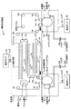
図1は、本発明の実施の形態にかかる薄膜形成装置1を示す図である。
Hereinafter, a thin film forming apparatus and a thin film forming method according to an embodiment of the present invention will be described in detail with reference to the drawings.
FIG. 1 is a diagram showing a thin film forming apparatus 1 according to an embodiment of the present invention.
薄膜形成装置1には搬送室3、成膜室5a、5bが形成され、搬送室3にはバルブ7cを介して真空ポンプ9cが、成膜室5aにはバルブ7aを介して真空ポンプ9aが、成膜室5bにはバルブ7bを介して真空ポンプ9bが設けられる。真空排気手段としての真空ポンプ9aないし9cは、ドライポンプ、ターボ分子ポンプ、クライオポンプが用いられており、9.0×10⁻⁵Paまで減圧可能である。
The thin film forming apparatus 1 includes a
搬送室3内には、搬送手段として巻出しドラム13およびガイドローラー19aないし19pが設けられている。フィルム15のロール状のフィルム原反11が、巻出しドラム13に取り付けられ、フィルム15の巻出しを自在に行うことができる。
In the
フィルム15の材料としては、ポリエチレンテレフタレートフィルム、ポリブチレンテレフタレートフィルム、ポリエチレンナフタレートフィルム、ポリカーボネートフィルム、ポリアミド、ポリイミド、ポリアミドイミド、ポリアリレートフィルム、ポリエーテルスルホンフィルム、ポリスルホンフィルム、ポリアリレート、ノルボルネンを含む環状オレフィンポリマー、アクリル樹脂、エポキシ樹脂およびそれらの組み合わせが挙げられる。 Examples of the material of the film 15 include polyethylene terephthalate film, polybutylene terephthalate film, polyethylene naphthalate film, polycarbonate film, polyamide, polyimide, polyamideimide, polyarylate film, polyethersulfone film, polysulfone film, polyarylate, and a ring containing norbornene. Examples include olefin polymers, acrylic resins, epoxy resins, and combinations thereof.
フィルム15の厚さは、好ましくは12〜200μmであり、より好ましくは100μmである。フィルム15の厚さが前記範囲内にあると、曲げやすい上に搬送中に破けることも無く、本発明にかかる薄膜形成装置で取り扱いやすい。 The thickness of the film 15 is preferably 12 to 200 μm, more preferably 100 μm. When the thickness of the film 15 is within the above range, the film 15 is easy to bend and is not broken during conveyance, and is easy to handle with the thin film forming apparatus according to the present invention.
フィルム15の移動速度は特に限定されないが、好ましくは0.01m/minから10m/minであり、より好ましくは0.1m/minである。 The moving speed of the film 15 is not particularly limited, but is preferably 0.01 m / min to 10 m / min, more preferably 0.1 m / min.
搬送室3には、巻出しドラム13により巻き出されたフィルム15から水分を除去するために加熱手段17aないし17fと、加熱手段中でフィルム15を移動させるためのガイドローラー19aないし19eが設けられている。図1においては、6個の加熱手段によりフィルム15の両面を各面3回ずつ加熱しているが、フィルム15の種類により、加熱手段17aないし17fの数を減らしても増やしてもよい。
The
加熱手段17aないし17fの種類としては、減圧下でフィルムを100℃程度まで加熱できるものであれば、特に限られないが、好ましくは、赤外線加熱装置、マイクロ波加熱装置、加熱ドラムである。 The type of the heating means 17a to 17f is not particularly limited as long as the film can be heated to about 100 ° C. under reduced pressure, but is preferably an infrared heating device, a microwave heating device, or a heating drum.
赤外線加熱装置とは赤外線発生手段から赤外線をフィルムに放射することで加熱する装置である。また、マイクロ波加熱装置とは、マイクロ波発生手段からマイクロ波をフィルムに照射することで加熱する装置である。また、加熱ドラムとは、ドラム表面の温度を高くして、巻き取ったフィルムを接触部分から熱を伝導させることでフィルムを加熱する装置である。 The infrared heating device is a device that heats the film by emitting infrared rays from the infrared ray generating means. Moreover, a microwave heating apparatus is an apparatus heated by irradiating a film with a microwave from a microwave generation means. The heating drum is a device that heats the film by increasing the temperature of the drum surface and conducting heat from the contact portion of the wound film.
搬送室3には、加熱されたフィルム15を、成膜室5aへ導くためのガイドローラー19f〜19gが設けられている。ガイドローラー19gの前にはフィルム15を前処理する前処理手段21aが設けられている。
The
前処理手段21aは、コロナ処理装置、低温プラズマ処理装置、グロー放電処理装置などである。これら手段を講じることにより、フィルムの樹脂表面の形状、化学的性状を変化させ、フィルムとフィルム上に形成される薄膜との密着性を向上させることができる。 The pretreatment means 21a is a corona treatment device, a low temperature plasma treatment device, a glow discharge treatment device, or the like. By taking these measures, the shape and chemical properties of the resin surface of the film can be changed, and the adhesion between the film and the thin film formed on the film can be improved.
成膜室5a内には、前処理が行われたフィルム15を巻取るコーティングドラム23aが設けられている。コーティングドラム23aは一部が搬送室3に露出しており、フィルム15はコーティングドラム23aに巻き取られながら搬送室3から成膜室5aに移動する。
In the
成膜室5aおよび5bは搬送室3と接して設けられており、フィルム15を大気に触れさせないままに移動可能である。また、成膜室5aと搬送室3の間は、矩形の穴により接続されており、その矩形の穴を通じてコーティングドラム23aの一部が搬送室3側に飛び出しており、搬送室3の壁とコーティングドラム23aの間に隙間が開いており、その隙間を通じてフィルム15は搬送室3から成膜室5aへ移動可能である。搬送室3と成膜室5bとの間も同様の構造になっており、フィルム15を大気に触れさせずに移動可能である。
The
コーティングドラム23aは、フィルム15が加熱手段17による加熱後に改めて吸水することを防ぐことや、成膜手段25aによる薄膜形成時の熱によるフィルム15の収縮や破損を防ぐことを目的とする。
前記コーティングドラム23aは、ステンレスから形成されてもよく、−20℃から50℃までの温度調整手段を有してもよい。
The purpose of the coating drum 23a is to prevent the film 15 from absorbing water again after being heated by the heating means 17, and to prevent shrinkage or breakage of the film 15 due to heat when forming a thin film by the
The coating drum 23a may be made of stainless steel and may have a temperature adjusting means from −20 ° C. to 50 ° C.
また、成膜室5aには、コーティングドラム23aの一部を覆うように、成膜手段25aが設けられている。フィルム15の片面に薄膜が形成される。
The
成膜手段25aには、バルブ29aを介してガス供給口27aが設けられており、ガス供給口27aには、薄膜を形成する物質に応じてさまざまなガスが必要により供給される。
The
成膜手段25aとしては、真空成膜装置、スパッタリング装置、イオンプレーティング成膜装置、イオンビームアシスト成膜装置、クラスターイオンビーム成膜装置、プラズマCVD成膜装置、プラズマ重合成膜装置、熱CVD成膜装置、触媒反応型CVD成膜装置などがある。
As the
成膜手段25aには、1つの成膜装置を設けてもよいし、2以上の同種または異種の成膜装置を設けてもよい。
The
1つの成膜装置で形成する薄膜の厚さは、好ましくは20nmから200nmであり、より好ましくは100nmである。 The thickness of the thin film formed by one film forming apparatus is preferably 20 nm to 200 nm, and more preferably 100 nm.
1つの成膜装置で厚く薄膜を形成すると、その薄膜は応力のために脆くなり、クラックが発生してガスバリア性が著しく低下することや、搬送時または巻取り時に薄膜が剥離することが生じる。そのため、ガスバリア性薄膜の厚い層を得るには、複数の成膜装置を設け、同じ物質の薄膜を複数回形成することが好ましい。 When a thin film is formed thickly by one film forming apparatus, the thin film becomes brittle due to stress, cracks are generated, the gas barrier property is remarkably lowered, and the thin film is peeled off during transportation or winding. Therefore, in order to obtain a thick layer of a gas barrier thin film, it is preferable to provide a plurality of film forming apparatuses and form a thin film of the same substance a plurality of times.
また、複数の成膜装置により、異なる材料の薄膜を形成してもよく、その場合には、ガスバリア性だけでなく、さまざま機能を付与された多層膜が得られる。 In addition, thin films of different materials may be formed by a plurality of film forming apparatuses. In that case, a multilayer film having various functions as well as gas barrier properties can be obtained.
薄膜を形成する物質は、特に限定されないが、ガスバリア性薄膜として使用する際には、ケイ素酸化物、ケイ素窒化物、ケイ素酸化窒化物、ケイ素炭化物、酸化アルミニウム、酸化マグネシウム、酸化チタン、酸化スズ、酸化インジウム、酸化亜鉛、酸化ジルコニウム等の金属酸化物、またはこれらの金属窒化物、炭化物、およびこれらの混合物が挙げられる。 The material forming the thin film is not particularly limited, but when used as a gas barrier thin film, silicon oxide, silicon nitride, silicon oxynitride, silicon carbide, aluminum oxide, magnesium oxide, titanium oxide, tin oxide, Examples thereof include metal oxides such as indium oxide, zinc oxide, and zirconium oxide, or metal nitrides, carbides, and mixtures thereof.
コーティングドラム23aにより再度搬送室3に移動させられた、片面に薄膜を形成されたフィルム15を、次の成膜室5bに導くためにガイドローラー19h〜19mが搬送室3に設けられている。搬送室3には、フィルム15がコーティングドラム23bに巻き取られる前に前処理する前処理手段21bが設けられている。前処理手段21bは前処理手段21aと同様である。
成膜室5bには、成膜室5aと同様に、コーティングドラム23bおよび成膜手段25bが設けられている。成膜手段25bは、成膜手段25aと同様に、バルブ29bを介してガス供給口27bが設けられている。片面に薄膜を形成させたフィルム15は成膜手段25bにより、他面に薄膜が形成され、最終的にはフィルム15の両面に薄膜が形成される。コーティングドラム23b、成膜手段25b、ガス供給口27b、バルブ29bは、それぞれ、コーティングドラム23a、成膜手段25a、ガス供給口27a、バルブ29aと同様である。
Similar to the
コーティングドラム23bにより再度搬送室3に移動させられた、両面に薄膜が形成されたフィルム15を、巻取りドラム31に導くためにガイドローラー19n〜19pが搬送室3に設けられている。搬送室3には、薄膜が形成されたフィルム15をロール状に巻き取るため、巻取り手段としての巻取りドラム31が設けられている。
次に、薄膜形成装置1の動作について説明する。ロール状のフィルム原反11を、搬送室3内の巻出しドラム13に設置し、搬送室内3と成膜室5aおよび5b内を真空ポンプ17aないし17cにより減圧する。
Next, the operation of the thin film forming apparatus 1 will be described. The roll-shaped film original 11 is installed on the unwinding
所定の圧力に達したら、巻出しドラム13により、フィルム原反11からフィルム15を巻き出す。フィルム15を加熱手段17aないし17fにより加熱し、フィルム15内部の水分を薄膜形成前に除去する。
When the predetermined pressure is reached, the film 15 is unwound from the
加熱されたフィルム15を、前処理手段21aに導き、前処理を行う。前処理されたフィルム15を、コーティングドラム23aに巻き取りつつ、搬送室3から成膜室5aに移動する。コーティングドラム23aに巻き取られたフィルム15の片面に、成膜手段25aにより薄膜を形成する。
The heated film 15 is guided to the pretreatment means 21a to perform pretreatment. The pretreated film 15 is moved from the
片面に薄膜が形成されたフィルム15を、コーティングドラム23aにより再度搬送室3に移動する。その後ガイドローラー19hないし19mにより搬送室3内を移動し、前処理手段21bにより前処理する。薄膜が形成されていない面が表になるようにコーティングドラム23bに巻き取り、成膜室5bに移動する。成膜室5b内では、フィルム15の他面に成膜手段25bにより薄膜を形成する。
The film 15 having a thin film formed on one side is moved again to the
両面に薄膜が形成されたフィルム15を、コーティングドラム23bにより再度搬送室3に移動し、フィルム15を巻取りドラム31によりロール状に巻き取る。
The film 15 with the thin film formed on both sides is moved again to the
このように、本実施の形態によれば、薄膜形成前にフィルム15を加熱し、フィルム15が吸着していた水を除去するため、成膜手段25aおよび25b内の雰囲気が改善され、均質かつ高品質なガスバリアフィルムを得ることが可能になる。 Thus, according to the present embodiment, the film 15 is heated before the thin film is formed, and the water adsorbed by the film 15 is removed, so that the atmosphere in the film forming means 25a and 25b is improved, and A high-quality gas barrier film can be obtained.
特に、チッ化ケイ素の薄膜を形成するときには、フィルム15に吸着していた水が除去されているため、成膜手段内25aおよび25bの雰囲気中の酸素濃度が減少し、酸素組成の低い酸化チッ化ケイ素薄膜を得ることができる。 In particular, when the silicon nitride thin film is formed, the water adsorbed on the film 15 is removed, so that the oxygen concentration in the atmosphere of the film forming means 25a and 25b is reduced, and the oxygen nitride having a low oxygen composition is reduced. A silicon silicide thin film can be obtained.
また、フィルム15を大気に触れさせることなく同時に両面に薄膜を形成できるために、保管中の基材フィルムの吸湿と、形成した薄膜の変性や剥離を防ぐことができ、安定したガスバリアフィルムを得ることができる。 Moreover, since a thin film can be formed on both surfaces simultaneously without exposing the film 15 to the atmosphere, moisture absorption of the base film during storage, and denaturation and peeling of the formed thin film can be prevented, and a stable gas barrier film is obtained. be able to.
次に、図1に示す薄膜形成装置1を用いて実際に薄膜を形成した際の結果について説明する。 Next, the results when the thin film is actually formed using the thin film forming apparatus 1 shown in FIG. 1 will be described.
図1に示す成膜手段25a,25bに、成膜装置としてデュアルマグネトロンスパッタリング装置を配置した。このスパッタリング装置にはシリコンターゲットを装着した。また、加熱手段17aないし17fとして、赤外線加熱装置を配置した。 In the film forming means 25a and 25b shown in FIG. 1, a dual magnetron sputtering apparatus is disposed as a film forming apparatus. This sputtering apparatus was equipped with a silicon target. In addition, an infrared heating device was disposed as the heating means 17a to 17f.
ついで、フィルム原反11として幅30cmのロール状の2軸延伸ポリエチレンナフタレートフィルム(帝人デュポン製 PENフィルムQ65 厚さ100μm)を準備し、この樹脂フィルムの未処理面側を外側として巻出しドラム13に装着した。
Next, a roll-shaped biaxially stretched polyethylene naphthalate film (PEN film Q65 manufactured by Teijin DuPont Co., Ltd., thickness: 100 μm) having a width of 30 cm is prepared as the
次に、搬送室3、成膜室5aおよび成膜室5b内を真空引きする。ドライポンプ、ターボ分子ポンプで10−2Pa台に減圧した後、クライオポンプを用いて到達真空度9.0×10⁻⁵Paまで減圧した。ついで、コーティングドラム23aおよび23bを50℃に上昇させた後、樹脂フィルム15を0.1m/minの速度で搬送し、赤外線加熱装置17aないし17fを100℃に設定して脱ガス処理を行った。
Next, the inside of the
成膜時の添加ガスとして、窒素ガス(大陽東洋酸素(株)製(純度99.9999%以上)および、アルゴンガス(大陽東洋酸素(株)製(純度99.9999%以上)を準備し、ガス供給口27aおよび27bより、成膜手段25aおよび25bに供給できるようにした。成膜手段25aおよび25b内に窒素ガスを流量15sccmで、アルゴンガスを流量20sccmでそれぞれ導入するとともに、コーティングドラム23aおよび23bを0℃に設定した後、樹脂フィルムを走行させ、電力を1.0kW投入し、成膜手段25a内圧力を1.0×10⁻¹Paに保ちながら薄膜形成を開始した。成膜手段25aおよび25bは同じ条件である。なお、sccmとは、standard cubic centimeter per minute の略である。
Nitrogen gas (manufactured by Taiyo Toyo Oxygen Co., Ltd. (purity 99.9999% or more)) and argon gas (manufactured by Taiyo Toyo Oxygen Co., Ltd. (purity 99.9999% or more)) are prepared as additive gases during film formation. The
樹脂フィルム15上にチッ化ケイ素からなるガスバリア性薄膜を形成して、ガスバリアフィルムを得た。成膜手段25aおよび25bへの供給ガスに酸素は含まれていないが、樹脂フィルム15に含まれる水により、成膜雰囲気には酸素が含まれることとなり、形成されるガスバリア性薄膜は純粋なチッ化ケイ素ではなく、酸化チッ化ケイ素になる。樹脂フィルム15の走行速度は、薄膜形成開始時点で形成される酸化チッ化ケイ素膜の膜厚が100nmになるように設定した。このような酸化チッ化ケイ素の薄膜を400mの樹脂フィルムに連続して形成した。 A gas barrier thin film made of silicon nitride was formed on the resin film 15 to obtain a gas barrier film. Although oxygen is not included in the gas supplied to the film forming means 25a and 25b, oxygen is included in the film forming atmosphere due to water contained in the resin film 15, and the formed gas barrier thin film is a pure chip. It becomes silicon oxide silicon instead of silicon oxide. The running speed of the resin film 15 was set so that the thickness of the silicon nitride oxide film formed at the start of thin film formation was 100 nm. Such a silicon oxide thin film was continuously formed on a 400 m resin film.
上記の薄膜形成の開始部位および最終部位である酸化チッ化ケイ素膜についてX線光電子分光法により、酸素成分の原子数量比を測定したところ、結果は表1のようであった。開始部位では8.1%であったのに対し最終部位は7.4%であった。また、裏面の酸素成分の原子数量比は開始部位で10.3%であるのに対し、最終部位は8.8%であった。これにより、酸素成分がほとんど変化しておらず安定した薄膜形成が維持されている事が確認された。 When the atomic ratio of oxygen components was measured by X-ray photoelectron spectroscopy for the silicon nitride oxide film, which was the starting site and the final site of the above thin film formation, the results were as shown in Table 1. The starting site was 8.1%, whereas the final site was 7.4%. Further, the atomic quantity ratio of the oxygen component on the back surface was 10.3% at the start site, whereas it was 8.8% at the final site. Thereby, it was confirmed that the oxygen component hardly changed and the stable thin film formation was maintained.

(比較例)
これに対して、比較例として樹脂フィルムに加熱処理を施さずに片面のみ薄膜を形成し、他は実施例と同様にして片面に薄膜が形成されたフィルムを作製した。
上記の連続成膜の開始部位および最終部位である酸化チッ化ケイ素膜について、酸素成分の原子数量比を測定したところ、結果は表2のようであった。開始部位では18.2%であったのに対し、最終部位は13.4%であった。酸素組成が時間により変化している事が確認された。
(Comparative example)
On the other hand, as a comparative example, a thin film was formed only on one side without subjecting the resin film to heat treatment, and a film having a thin film formed on one side was prepared in the same manner as in the examples.
When the atomic ratio of oxygen components was measured for the silicon nitride oxide film that was the start and end of the continuous film formation, the results were as shown in Table 2. The starting site was 18.2%, while the final site was 13.4%. It was confirmed that the oxygen composition changed with time.
実施例と比較例を比べると、実施例のガスバリアフィルムのほうが、含まれる酸素の量自体が少なくなっている上に、酸素の量のばらつきが少なく、より好ましいガスバリアフィルムが得られたことがわかる。 Comparing the examples and the comparative example, it can be seen that the gas barrier film of the example has a smaller amount of oxygen contained and less variation in the amount of oxygen, and a more preferable gas barrier film was obtained. .
以上、添付図面を参照しながら、本発明にかかる薄膜形成装置および薄膜形成方法の好適な実施形態について説明したが、本発明は係る例に限定されない。当業者であれば、本願で開示した技術的思想の範疇内において、各種の変更例または修正例に想到しえることは明らかであり、それらについても当然に本発明の技術的範囲に属するものと了解される。 The preferred embodiments of the thin film forming apparatus and the thin film forming method according to the present invention have been described above with reference to the accompanying drawings, but the present invention is not limited to such examples. It will be apparent to those skilled in the art that various changes and modifications can be made within the scope of the technical idea disclosed in the present application, and these are naturally within the technical scope of the present invention. Understood.
1………薄膜形成装置
3………搬送室
5………成膜室
7………バルブ
9………真空ポンプ
11………フィルム原反
13………巻出しドラム
15………フィルム
17………加熱手段
19………ガイドローラー
21………前処理手段
23………コーティングドラム
25………成膜手段
27………ガス供給口
29………バルブ
31………巻取りドラム
DESCRIPTION OF SYMBOLS 1 ......... Thin film-forming
Claims (12)
前記フィルムを加熱する加熱手段と、
前記フィルムの片面に薄膜を形成する第1の成膜手段と、
前記フィルムの他面に薄膜を形成する第2の成膜手段と、
両面に薄膜が形成された前記フィルムをロール状に巻き取る巻取り手段と、
を具備することを特徴とした薄膜形成装置。 A conveying means for unwinding and conveying the roll film;
Heating means for heating the film;
First film forming means for forming a thin film on one side of the film;
A second film forming means for forming a thin film on the other surface of the film;
A winding means for winding the film having a thin film formed on both sides into a roll;
A thin film forming apparatus comprising:
前記搬送室内でロール状のフィルムを巻き出す搬送工程と、
前記フィルムを加熱する加熱工程と、
前記フィルムの片面に薄膜を形成する第1の成膜工程と、
前記フィルムの他面に薄膜を形成する第2の成膜工程と、
前記フィルムを巻き取る巻取り工程と、
からなることを特徴とする薄膜形成方法。 An evacuation step of depressurizing the transfer chamber and the film formation chamber;
A conveying step of unwinding a roll film in the conveying chamber;
A heating step of heating the film;
A first film forming step of forming a thin film on one side of the film;
A second film forming step of forming a thin film on the other surface of the film;
A winding process for winding the film;
A thin film forming method comprising:
Priority Applications (1)
| Application Number | Priority Date | Filing Date | Title |
|---|---|---|---|
| JP2007177287A JP2009013473A (en) | 2007-07-05 | 2007-07-05 | Thin-film-forming apparatus and thin-film-forming method |
Applications Claiming Priority (1)
| Application Number | Priority Date | Filing Date | Title |
|---|---|---|---|
| JP2007177287A JP2009013473A (en) | 2007-07-05 | 2007-07-05 | Thin-film-forming apparatus and thin-film-forming method |
Publications (1)
| Publication Number | Publication Date |
|---|---|
| JP2009013473A true JP2009013473A (en) | 2009-01-22 |
Family
ID=40354738
Family Applications (1)
| Application Number | Title | Priority Date | Filing Date |
|---|---|---|---|
| JP2007177287A Pending JP2009013473A (en) | 2007-07-05 | 2007-07-05 | Thin-film-forming apparatus and thin-film-forming method |
Country Status (1)
| Country | Link |
|---|---|
| JP (1) | JP2009013473A (en) |
Cited By (4)
| Publication number | Priority date | Publication date | Assignee | Title |
|---|---|---|---|---|
| JP2013049916A (en) * | 2011-07-29 | 2013-03-14 | Nitto Denko Corp | Method for double-side vacuum film formation and laminate obtainable by the method |
| JP2014141707A (en) * | 2013-01-23 | 2014-08-07 | Konica Minolta Inc | Method of manufacturing functional film |
| US9109284B2 (en) | 2010-10-06 | 2015-08-18 | Ulvac, Inc. | Vacuum processing apparatus |
| JP2016014161A (en) * | 2014-06-30 | 2016-01-28 | トーカロ株式会社 | Polymer elastomer member excellent in antifouling property, and roll member using the same |
Citations (6)
| Publication number | Priority date | Publication date | Assignee | Title |
|---|---|---|---|---|
| JPS6017074A (en) * | 1983-07-09 | 1985-01-28 | Konishiroku Photo Ind Co Ltd | Thin film forming device and treating chamber unit constituting said device |
| JPS6194220A (en) * | 1984-10-15 | 1986-05-13 | Toshiba Corp | Magnetic recording medium and its manufacture |
| JPS6255559U (en) * | 1985-09-28 | 1987-04-06 | ||
| JP2000338901A (en) * | 1999-06-01 | 2000-12-08 | Matsushita Electric Ind Co Ltd | Manufacture of flexible display substrate |
| JP2005169994A (en) * | 2003-12-15 | 2005-06-30 | Dainippon Printing Co Ltd | Gas barrier sheet |
| JP2006249471A (en) * | 2005-03-09 | 2006-09-21 | Fuji Photo Film Co Ltd | Film deposition method |
-
2007
- 2007-07-05 JP JP2007177287A patent/JP2009013473A/en active Pending
Patent Citations (6)
| Publication number | Priority date | Publication date | Assignee | Title |
|---|---|---|---|---|
| JPS6017074A (en) * | 1983-07-09 | 1985-01-28 | Konishiroku Photo Ind Co Ltd | Thin film forming device and treating chamber unit constituting said device |
| JPS6194220A (en) * | 1984-10-15 | 1986-05-13 | Toshiba Corp | Magnetic recording medium and its manufacture |
| JPS6255559U (en) * | 1985-09-28 | 1987-04-06 | ||
| JP2000338901A (en) * | 1999-06-01 | 2000-12-08 | Matsushita Electric Ind Co Ltd | Manufacture of flexible display substrate |
| JP2005169994A (en) * | 2003-12-15 | 2005-06-30 | Dainippon Printing Co Ltd | Gas barrier sheet |
| JP2006249471A (en) * | 2005-03-09 | 2006-09-21 | Fuji Photo Film Co Ltd | Film deposition method |
Cited By (4)
| Publication number | Priority date | Publication date | Assignee | Title |
|---|---|---|---|---|
| US9109284B2 (en) | 2010-10-06 | 2015-08-18 | Ulvac, Inc. | Vacuum processing apparatus |
| JP2013049916A (en) * | 2011-07-29 | 2013-03-14 | Nitto Denko Corp | Method for double-side vacuum film formation and laminate obtainable by the method |
| JP2014141707A (en) * | 2013-01-23 | 2014-08-07 | Konica Minolta Inc | Method of manufacturing functional film |
| JP2016014161A (en) * | 2014-06-30 | 2016-01-28 | トーカロ株式会社 | Polymer elastomer member excellent in antifouling property, and roll member using the same |
Similar Documents
| Publication | Publication Date | Title |
|---|---|---|
| JP5081712B2 (en) | Deposition equipment | |
| JP5092624B2 (en) | Method and apparatus for producing gas barrier film | |
| JP5136114B2 (en) | Method and apparatus for producing gas barrier film | |
| JP5895687B2 (en) | Gas barrier film | |
| TW201802291A (en) | Roll-to-roll atomic layer deposition apparatus and method | |
| JP4536784B2 (en) | Method for producing functional film | |
| TWI567219B (en) | Gas barrier film and method of producing the same | |
| JP2010247369A (en) | Method for producing gas-barrier laminate and gas-barrier laminate | |
| JP6096783B2 (en) | Coating preparation method by atmospheric pressure plasma method | |
| JP2002322561A (en) | Sputtering film deposition method | |
| WO2016009801A1 (en) | Gas barrier film and electronic device | |
| JP2009013473A (en) | Thin-film-forming apparatus and thin-film-forming method | |
| JP2011046060A (en) | Gas barrier film and method for manufacturing gas barrier film | |
| JP5212356B2 (en) | Method for producing roll-shaped resin film having transparent conductive film and organic electroluminescence device using the same | |
| JP2001073133A (en) | System and method for depositing vacuum thin film | |
| JP6617701B2 (en) | Gas barrier film and method for producing the same | |
| WO2015008708A1 (en) | Electronic device | |
| JP2005320583A (en) | Gas-barrier transparent plastic film, manufacturing method therefor and organic electroluminescence element using the gas-barrier transparent plastic film | |
| JP2007063639A (en) | Winding type composite vacuum surface treatment device, and surface treatment method for film | |
| WO2005108055A1 (en) | Film for display board and method for manufacturing organic el element and aluminum oxide thin film | |
| JP2004339602A (en) | Vacuum film deposition system for film, and plastic film using the same | |
| WO2016166986A1 (en) | Laminate and method for producing same | |
| JPWO2016178391A1 (en) | Elongated gas barrier film and method for producing the same, and short gas barrier film and method for producing the same | |
| JPWO2016178391A6 (en) | Elongated gas barrier film and method for producing the same, and short gas barrier film and method for producing the same | |
| WO2015083681A1 (en) | Gas barrier film and production method therefor |
Legal Events
| Date | Code | Title | Description |
|---|---|---|---|
| A621 | Written request for application examination |
Free format text: JAPANESE INTERMEDIATE CODE: A621 Effective date: 20100416 |
|
| A977 | Report on retrieval |
Free format text: JAPANESE INTERMEDIATE CODE: A971007 Effective date: 20110729 |
|
| A131 | Notification of reasons for refusal |
Free format text: JAPANESE INTERMEDIATE CODE: A131 Effective date: 20110816 |
|
| A521 | Written amendment |
Free format text: JAPANESE INTERMEDIATE CODE: A523 Effective date: 20111006 |
|
| A131 | Notification of reasons for refusal |
Free format text: JAPANESE INTERMEDIATE CODE: A131 Effective date: 20120508 |
|
| A521 | Written amendment |
Free format text: JAPANESE INTERMEDIATE CODE: A523 Effective date: 20120704 |
|
| A02 | Decision of refusal |
Free format text: JAPANESE INTERMEDIATE CODE: A02 Effective date: 20130402 |