JP2008538317A - Interconnect modular pathway device - Google Patents

Interconnect modular pathway device Download PDF

Info

Publication number
JP2008538317A
JP2008538317A JP2008507816A JP2008507816A JP2008538317A JP 2008538317 A JP2008538317 A JP 2008538317A JP 2008507816 A JP2008507816 A JP 2008507816A JP 2008507816 A JP2008507816 A JP 2008507816A JP 2008538317 A JP2008538317 A JP 2008538317A
Authority
JP
Japan
Prior art keywords
modular member
interconnectable
modular
horizontal
outlet
Prior art date
Legal status (The legal status is an assumption and is not a legal conclusion. Google has not performed a legal analysis and makes no representation as to the accuracy of the status listed.)
Pending
Application number
JP2008507816A
Other languages
Japanese (ja)
Other versions
JP2008538317A5 (en
Inventor
アンドリュー コンフォート,
Original Assignee
キュー−バ−メイズ インコーポレイテッド
Priority date (The priority date is an assumption and is not a legal conclusion. Google has not performed a legal analysis and makes no representation as to the accuracy of the date listed.)
Filing date
Publication date
Application filed by キュー−バ−メイズ インコーポレイテッド filed Critical キュー−バ−メイズ インコーポレイテッド
Publication of JP2008538317A publication Critical patent/JP2008538317A/en
Publication of JP2008538317A5 publication Critical patent/JP2008538317A5/ja
Pending legal-status Critical Current

Links

Images

Classifications

    • AHUMAN NECESSITIES
    • A63SPORTS; GAMES; AMUSEMENTS
    • A63HTOYS, e.g. TOPS, DOLLS, HOOPS OR BUILDING BLOCKS
    • A63H33/00Other toys
    • A63H33/04Building blocks, strips, or similar building parts
    • A63H33/06Building blocks, strips, or similar building parts to be assembled without the use of additional elements
    • A63H33/08Building blocks, strips, or similar building parts to be assembled without the use of additional elements provided with complementary holes, grooves, or protuberances, e.g. dovetails
    • AHUMAN NECESSITIES
    • A63SPORTS; GAMES; AMUSEMENTS
    • A63FCARD, BOARD, OR ROULETTE GAMES; INDOOR GAMES USING SMALL MOVING PLAYING BODIES; VIDEO GAMES; GAMES NOT OTHERWISE PROVIDED FOR
    • A63F7/00Indoor games using small moving playing bodies, e.g. balls, discs or blocks
    • A63F7/22Accessories; Details
    • A63F7/36Constructional details not covered by groups A63F7/24 - A63F7/34, i.e. constructional details of rolling boards, rims or play tables, e.g. frame, game boards, guide tracks
    • A63F7/3622Specially shaped rolling boards for the balls, e.g. ball tracks
    • AHUMAN NECESSITIES
    • A63SPORTS; GAMES; AMUSEMENTS
    • A63HTOYS, e.g. TOPS, DOLLS, HOOPS OR BUILDING BLOCKS
    • A63H18/00Highways or trackways for toys; Propulsion by special interaction between vehicle and track
    • AHUMAN NECESSITIES
    • A63SPORTS; GAMES; AMUSEMENTS
    • A63HTOYS, e.g. TOPS, DOLLS, HOOPS OR BUILDING BLOCKS
    • A63H33/00Other toys
    • A63H33/04Building blocks, strips, or similar building parts
    • A63H33/06Building blocks, strips, or similar building parts to be assembled without the use of additional elements
    • A63H33/08Building blocks, strips, or similar building parts to be assembled without the use of additional elements provided with complementary holes, grooves, or protuberances, e.g. dovetails
    • A63H33/086Building blocks, strips, or similar building parts to be assembled without the use of additional elements provided with complementary holes, grooves, or protuberances, e.g. dovetails with primary projections fitting by friction in complementary spaces between secondary projections, e.g. sidewalls
    • AHUMAN NECESSITIES
    • A63SPORTS; GAMES; AMUSEMENTS
    • A63FCARD, BOARD, OR ROULETTE GAMES; INDOOR GAMES USING SMALL MOVING PLAYING BODIES; VIDEO GAMES; GAMES NOT OTHERWISE PROVIDED FOR
    • A63F7/00Indoor games using small moving playing bodies, e.g. balls, discs or blocks
    • A63F7/22Accessories; Details
    • A63F7/36Constructional details not covered by groups A63F7/24 - A63F7/34, i.e. constructional details of rolling boards, rims or play tables, e.g. frame, game boards, guide tracks
    • A63F2007/3655Collapsible, foldable or rollable parts
    • A63F2007/3662Collapsible, foldable or rollable parts modular, e.g. with connections between modules
    • AHUMAN NECESSITIES
    • A63SPORTS; GAMES; AMUSEMENTS
    • A63FCARD, BOARD, OR ROULETTE GAMES; INDOOR GAMES USING SMALL MOVING PLAYING BODIES; VIDEO GAMES; GAMES NOT OTHERWISE PROVIDED FOR
    • A63F7/00Indoor games using small moving playing bodies, e.g. balls, discs or blocks
    • A63F7/22Accessories; Details
    • A63F7/36Constructional details not covered by groups A63F7/24 - A63F7/34, i.e. constructional details of rolling boards, rims or play tables, e.g. frame, game boards, guide tracks
    • A63F7/40Balls or other moving playing bodies, e.g. pinballs or discs used instead of balls

Abstract

The present invention provides for a plurality of interconnectable modular members that may create a pathway system with multiple entrances into the upper portion of each member and at least one exit from the lower portion of each member, thereby providing for a variety of convergence and divergence possibilities. The pathway system is suitable for receiving and transporting marbles and other spherical objects from one member to another. The modular members may be interlinked via male/female connectors to create a variety of configurations.

Description

(関連出願の参照)
本願は、米国仮出願第60/672,286号(2005年3月18日出願)、米国仮出願60/682,146号(2005年5月18日出願)、米国仮出願第60/696,611号(2005年7月5日出願)、米国仮出願第60/748,684号(2006年12月8日出願)の利益を主張する。これらの出願の各々の全容は、本明細書に引用される。
(Refer to related applications)
The present application includes US Provisional Application No. 60 / 672,286 (filed on March 18, 2005), US Provisional Application No. 60 / 682,146 (filed on May 18, 2005), US Provisional Application No. 60/696, 611 (filed on July 5, 2005) and US Provisional Application No. 60 / 748,684 (filed on December 8, 2006). The entire contents of each of these applications are cited herein.

(発明の概要)
本発明は、さまざまな収束と発散の可能性を提供するために、各部材の上部への複数の入口と、各部材の下部から少なくとも1つの入口とを備えるパスウェイシステムを作成することができる複数の相互接続可能なモジュール式部材を提供する。本発明のシステムは、ビー球のような球状物体の受領と運搬に適しており、図面により、本発明に従うさらにさまざまな原則と実施例が示される。
(Summary of Invention)
The present invention allows multiple pathway systems to be created with multiple entrances to the top of each member and at least one entrance from the bottom of each member to provide various convergence and divergence possibilities. An interconnectable modular member is provided. The system of the present invention is suitable for receiving and transporting a spherical object such as a marble, and the drawings illustrate further various principles and embodiments according to the present invention.

一実施例では、モジュール式部材は、一般的に立方体構造を有するが、その他さまざまな部材の形状が可能である。各立方体状の部材は、一般的に少なくとも1つの出口を定義する。例えば、部材の縦方向の面の開口により、立方体状の部材に水平方向の出口を定義できる。立方体状の部材は、1つから4つまでの水平歩行の出口を任意の場所に有することができるが、図面に示されているように、さまざまな数の出口を備えるその他の部材の構造と形状も可能である。立方体状の部材の別の構造は、縦方向の出口の部材であって、部材の下側に縦方向の出口を定義する。   In one embodiment, the modular member generally has a cubic structure, but various other member shapes are possible. Each cubic member generally defines at least one outlet. For example, a horizontal exit can be defined in a cubic member by opening the longitudinal surface of the member. The cube-shaped member can have one to four horizontal walk exits at any location, but as shown in the drawings, other member structures with different numbers of exits Shape is also possible. Another structure of the cubic member is a longitudinal outlet member, which defines a longitudinal outlet below the member.

モジュール式部材のいずれも、部材が1つ以上の水平方向の出口または単独の縦方向の出口を有するかどうかに関わらず、オス/メスのコネクタで他の同様な部材と相互接続できる。立方体状の部材の場合には、各部材は5つの入口を含むので、各部材は、5つまでのその他の部材の出口の収束を許可する。さらに、各部材は、部材により提供される出口の数に対応して、さまざまなレベルの発散を実現できる。   Any of the modular members can be interconnected with other similar members with male / female connectors regardless of whether the member has one or more horizontal outlets or a single longitudinal outlet. In the case of a cubic member, each member includes five inlets, so each member allows convergence of the outlets of up to five other members. Furthermore, each member can achieve different levels of divergence, corresponding to the number of outlets provided by the member.

本発明を使用すると、さまざまな接合の可能性が生まれる。例えば、水平方向の出口の立方体状の部材は、オスの水平方向のコネクタ、または各水平方向の出口の接合を定義することができるが、典型的に2つの縦方向の配列された部材を備えており、オプションで、その下から縦方向に配列された部材に接続する曲面の構成要素を備えていることより、U字形状を作成しており、さらに、部材の縦方向面の外側に突き出ており、部材の下側の位置であって水平方向出口のいずれかの側に配置されている。水平方向の出口部材と縦方向の出口部材両方のモジュール式部材のそれぞれは、典型的に、別の部材のオスのコネクタを受け止めて相互接続するために、部材の上部分に配置された4つのメスの水平方向のコネクタまたは接合も定義する。従って、相互接続された部材は、水平方向に結合される。   Using the present invention creates a variety of bonding possibilities. For example, a horizontal outlet cube-shaped member can define a male horizontal connector, or a junction of each horizontal outlet, but typically comprises two longitudinally aligned members. It has an optional curved component that connects to the members arranged in the vertical direction from the bottom, creating a U-shape, and further protruding outside the vertical surface of the member And located on either side of the horizontal outlet at the lower position of the member. Each of the modular members of both the horizontal outlet member and the vertical outlet member typically has four members disposed on the upper portion of the member for receiving and interconnecting the male connector of another member. It also defines a female horizontal connector or joint. Thus, the interconnected members are joined in the horizontal direction.

2つの水平方向に結合された立方体状の部材は、縦方向にねじれており、隣り合う部材の間に半分の段差の縦方向のずれを作り出す。その他の実施例では、この縦方向のオフセットは、ブロック半分のオフセット程度にできる。この偏移により、縦方向の部材の出口は隣圧部材の入口と一列に並ぶ。固体集団のブロックは、組み立てることが可能で、組み立てられると自動的に格子状効果になるので、隣り合う縦方向のカラムのブロックは半分の段差でねじれる。3次元格子の「偏移直交座標空間」(3D格子)は、組み立てられた任意のブロックの潜在的な位置を説明する。一体、格子、線形、平面、交差面、およびその他の構造が可能である。特定の構造を作成するために使用される基本的な構成は、縦列、スラローム、ジグザグ、単独らせん、および二重らせんである。   The two horizontally joined cube-shaped members are twisted in the vertical direction, creating a vertical shift in half steps between adjacent members. In other embodiments, this vertical offset can be as much as a half block offset. Due to this shift, the outlet of the longitudinal member is aligned with the inlet of the adjacent pressure member. Solid mass blocks can be assembled and, when assembled, automatically have a lattice effect, so adjacent vertical column blocks are twisted in half steps. The “shifted orthogonal coordinate space” (3D grid) of the three-dimensional grid describes the potential position of any assembled block. Monolithic, lattice, linear, planar, intersecting surfaces, and other structures are possible. The basic configurations used to create a particular structure are columns, slalom, zigzag, single helix, and double helix.

次の説明では、本発明の実施例が、好ましい実施例を含めて、図説と説明の目的において示される。これらは、包括的なものではなく、また、本発明を公開される正確な形式に限定することを目的としたものではない。例えば、立方体状の部材は、本発明の唯一の実施例であるが、他のさまざまな形状や構造のモジュール式部材は、説明される原則と同じにすることができる。上記の教示の点から、明らかな修正または変形が可能である。実施例は、本発明の原則とその実用化の最適な図説を提供するため、および、意図される特定の使用に適したさまざまな実施例とさまざまな修正により同業者が本発明を利用できるために選択および説明する。このような修正や変形すべては本発明の範囲内である。   In the following description, embodiments of the invention are presented for purposes of illustration and description, including preferred embodiments. They are not exhaustive and are not intended to limit the invention to the precise form disclosed. For example, a cube-shaped member is the only embodiment of the present invention, but the modular members of various other shapes and structures can be the same as described principles. Obvious modifications or variations are possible in light of the above teaching. The examples are intended to provide an optimal illustration of the principles of the invention and its practical application, and to enable one skilled in the art to use the invention with various examples and various modifications suitable for the particular intended use. To select and explain. All such modifications and variations are within the scope of the present invention.

(I.モジュール式部材)
本発明のモジュール式部材は、本明細書で公開される原則に一致するさまざまな形状と構造をとることができる。同様な部材は、相互接続可能であり、ある部材から別の接続された部材への一連の出口と入口によりパスウェイを形成することができる。これらのパスウェイは、ビー球のような球状物体またはその他適当な物体または液体の受領と運搬に適している。いくつかの同様な部材を接続すると、いくつかのパスウェイが作成され、出口と入口により生じる収束と発散は、組立物に入れられる球により実際に移動するパスウェイを決定する場合に無作為度を提供することができる。
(I. Modular members)
The modular members of the present invention can take a variety of shapes and configurations consistent with the principles disclosed herein. Similar members can be interconnected and a pathway can be formed by a series of outlets and inlets from one member to another connected member. These pathways are suitable for receiving and transporting a spherical object such as a ball or other suitable object or liquid. Connecting several similar members creates several pathways, and the convergence and divergence caused by the exit and entrance provides a random degree in determining the pathway actually moved by the spheres that are put into the assembly can do.

(A.入口と出口)
(i)部材の一般的属性
図1A−1L、2A−2L、3A−3L、4A−4L、5A−5J、6A−6I、7A−7J、8A−8I、9A−9I、10A−10I、11A−11J、12A−12Jおよび13A−13Jを参照すると、各モジュール式部材は、部材の特定の形状により決定される1つ以上の出口と複数の入口を定義する。
(A. Entrance and exit)
(I) General attributes of members 1A-1L, 2A-2L, 3A-3L, 4A-4L, 5A-5J, 6A-6I, 7A-7J, 8A-8I, 9A-9I, 10A-10I, 11A Referring to -11J, 12A-12J and 13A-13J, each modular member defines one or more outlets and a plurality of inlets determined by the particular shape of the member.

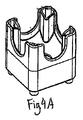
例えば、モジュール式部材が実質的に立方体の形状を有する実施例においては、図1A−1L、2A−2L、3A−3L、4A−4L、5A−5J、7A−7J、11A−11J、12A−12Jおよび13A−13Jに示されているように、各部材は少なくとも1つの出口といくつかの入口を有し、以下に詳細を説明するが、4つの水平方向の入口と1つの縦方向の入口と考えることができる。立方体の実施例では、部材は、部材の縦方向面に形成された1つから4つの水平方向の出口を有することができる。あるいは、代わりに、部材の下側に形成された単独の縦方向の出口を有することができる。2つの水平方向の出口のある立方体形状の部材は、部材の隣接または反対側のいずれかに出口を形成することができる。立方体状の実施例では、各部材は、その4つの縦方向の面それぞれおよび縦方向の入口に水平方向の入口を定義することもできる。   For example, in embodiments where the modular member has a substantially cubic shape, FIGS. 1A-1L, 2A-2L, 3A-3L, 4A-4L, 5A-5J, 7A-7J, 11A-11J, 12A- As shown in 12J and 13A-13J, each member has at least one outlet and several inlets, described in detail below, but with four horizontal inlets and one longitudinal inlet. Can be considered. In the cubic embodiment, the member can have one to four horizontal outlets formed in the longitudinal plane of the member. Alternatively, it can alternatively have a single longitudinal outlet formed on the underside of the member. A cube-shaped member with two horizontal outlets can form an outlet either on the adjacent or opposite side of the member. In the cubic embodiment, each member can also define a horizontal entrance at each of its four longitudinal faces and longitudinal entrance.

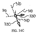
立方体部材の入口と出口は図14A−14Lに詳細が示されるが、入口は破線で示され、出口は矢印をつけた実線で示される。図14Aを参照すると、5つの入口(4つの「水平方向の」入口310と1つの「縦方向の」入口320)と1つの水平方向の出口330のための入口/出口パスウェイの模式図が示されているが、実際のモジュール式部材は示されていない。同じ入口/出口の概略図は、これらの入口310/320と出口330を定義している立方体状の部材10が図14Dに示されている。同様に、5つの入口310/320と2つの水平方向の出口330の入口/出口模式図が示されているが、実際の部材は示されていない。また、反対側の出口は図14Bに、隣側の出口は図14Cに示されている。これらの入口と出口を定義している立方体状の部材10とともに、対応する入口/出口の模式図は、それぞれ図14Eと14Fに示されている。3つの水平方向の出口330の入口/出口の模式図は図14Gと14Jに示されている。また、4つの水平歩行の出口330は図14Hと14Kに示されている。単独の縦方向の出口340の入口/出口の模式図は図14Iと14Lに示されている。   The inlet and outlet of the cube member are shown in detail in FIGS. 14A-14L, but the inlet is shown as a dashed line and the outlet is shown as a solid line with an arrow. Referring to FIG. 14A, a schematic diagram of an inlet / outlet pathway for five inlets (four “horizontal” inlets 310 and one “longitudinal” inlet 320) and one horizontal outlet 330 is shown. However, the actual modular members are not shown. A schematic view of the same inlet / outlet is shown in FIG. 14D with the cubic member 10 defining these inlets 310/320 and outlet 330. Similarly, an inlet / outlet schematic diagram of five inlets 310/320 and two horizontal outlets 330 is shown, but the actual components are not shown. The opposite outlet is shown in FIG. 14B and the adjacent outlet is shown in FIG. 14C. The corresponding inlet / outlet schematics, along with the cubic member 10 defining these inlets and outlets, are shown in FIGS. 14E and 14F, respectively. A schematic of the inlet / outlet of the three horizontal outlets 330 is shown in FIGS. 14G and 14J. Also, four horizontal walk outlets 330 are shown in FIGS. 14H and 14K. A schematic diagram of the inlet / outlet of a single longitudinal outlet 340 is shown in FIGS. 14I and 14L.

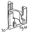
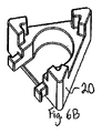
代わりの実施例では、モジュール式部材は、6A−6Iに示されるように、三角形状を有し、各部材20は少なくとも1つの出口、3つの水平方向の入口および1つの縦方向の入口を有する。三角形状の部材20は、部材20の縦方向の面に形成された1つから3つの間の水平方向の出口330を有することができる。あるいは、代わりに部材20の下側に形成される単独の縦方向の出口340を有することができる。三角形状の実施例では、各部材20は、その3つの縦方向の面のそれぞれに水平方向の入口310ならびに縦方向の入口320も定義する。   In an alternative embodiment, the modular members have a triangular shape, as shown in 6A-6I, and each member 20 has at least one outlet, three horizontal inlets and one longitudinal inlet. . Triangular member 20 can have between one and three horizontal outlets 330 formed on the longitudinal surface of member 20. Alternatively, it can alternatively have a single longitudinal outlet 340 formed under the member 20. In the triangular embodiment, each member 20 also defines a horizontal inlet 310 as well as a vertical inlet 320 on each of its three longitudinal faces.

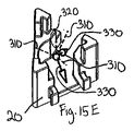
図15A、15D、15Gおよび15Jを参照すると、三角形の部材の入口/出口模式図が示されているが、実際の部材は示されていない。各模式図は、4つの入口310/320と1つ、2つ、および3つの水平方向の出口330はそれぞれ図15A、15Dおよび15Gに示される。また、単独の縦方向の出口340は図15Jに示される。対応する入口/出口の模式図は、図15B、15E、15Hおよび15Kの入口と出口を定義する三角形の部材20により示される。   Referring to FIGS. 15A, 15D, 15G and 15J, a schematic entry / exit view of a triangular member is shown, but the actual member is not shown. In each schematic diagram, four inlets 310/320 and one, two, and three horizontal outlets 330 are shown in FIGS. 15A, 15D, and 15G, respectively. A single longitudinal outlet 340 is also shown in FIG. 15J. A corresponding inlet / outlet schematic diagram is shown by the triangular member 20 defining the inlet and outlet of FIGS. 15B, 15E, 15H and 15K.

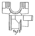
このように、立方体状の実施例では、モジュール式部材10は、4つの水平方向310と1つの縦方向320という合計で5つの入口と、1つから4つの出口を有する。また、三角形状の実施例では、モジュール式部材20は、3つの水平方向310と1つの縦方向320という合計で4つの入口と1つから3つの出口を有する。どちらの実施例の場合も、1つだけの出口のある部材は、水平方向出口330または縦方向出口240のいずれかを含むことができる。このように、モジュール式部材がn面を有する立方体、三角形、およびその他の実施例では、各部材はn+1個の入口と1からn個の出口を有する。この原則は、図8A−8Iに示されている十字形または「T型」の実施例などその他の実施例にも適用できる。   Thus, in the cubic embodiment, modular member 10 has a total of five inlets, one to four outlets, four horizontal directions 310 and one longitudinal direction 320. Also, in the triangular embodiment, modular member 20 has a total of four inlets and one to three outlets, three horizontal directions 310 and one longitudinal direction 320. In either embodiment, a member with only one outlet can include either a horizontal outlet 330 or a longitudinal outlet 240. Thus, in cubes, triangles, and other embodiments where the modular members have n-planes, each member has n + 1 inlets and 1 to n outlets. This principle can also be applied to other embodiments, such as the cross or “T” embodiment shown in FIGS. 8A-8I.

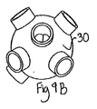
本発明の原則に一致するその他の実施例は、これらの入口/出口式に従わない数の入口と出口を含むことができる。例えば、球状または切断された8面体の部材は逸脱する場合がある。「立方球状」部材では、部材30は、5つの入口と1つから4つの出口を定義する。図9A−9Iは、別の視点から見た、1つの水平方向の出口330を備える「立方球状」部材30を示す。「立方球状」部材30の入口/出口の模式図と、立方体状部材10の入口/出口の模式図は、1から4つの同様に構成された水平方向の出口330を有することができる範囲で、類似している。「三角形状−球体状」部材では、部材40は、4つの入口と1つから3つの出口を定義する。図10A−10Iは、1つの水平方向の出口を備える「三角形状−球体状」部材40を、別の視点から見た図である。「三角形状−球体状」部材40の入口/出口模式図と、三角形状の部材20の入口/出口模式図は、1つから3つの同様に構成された水平方向の出口330を有することができる範囲で類似している。   Other embodiments consistent with the principles of the present invention may include a number of inlets and outlets that do not follow these inlet / outlet equations. For example, a spherical or cut octahedron member may deviate. In a “cubic spherical” member, member 30 defines five inlets and one to four outlets. FIGS. 9A-9I show a “cubic spherical” member 30 with one horizontal outlet 330 viewed from another perspective. The schematic diagram of the inlet / outlet of the “cubic spherical” member 30 and the schematic diagram of the inlet / outlet of the cubic member 10 are within a range that can have one to four similarly configured horizontal outlets 330, It is similar. In a “triangular-spherical” member, member 40 defines four inlets and one to three outlets. 10A-10I are views of a “triangular-spherical” member 40 with one horizontal outlet as seen from another perspective. The inlet / outlet schematic diagram of the “triangular-spherical” member 40 and the inlet / outlet schematic diagram of the triangular shaped member 20 can have one to three similarly configured horizontal outlets 330. Similar in scope.

本発明の側面は、同じ入口/出口原理に準じるモジュール式部材のさまざまな形状と構造である。例えば、部材の多数の別々の実施例は、本発明から逸脱することなく、同様なまたは同一の入口と出口構造を含むことができる。三角形状の部材20と三角形状−球体状部材40は、固有の物理的特徴を有するが、図15B、15E、15Hおよび15K(三角形状部材20)および図15C、15F、15Iおよび15L(「三角形−球体」部材40)(図16A、16B、16Cおよび16Dの内部通路とともに示される)に見られるように、同じ入口/出口構成を共有することができる。図15Aの入口/出口構成は、図15Bの三角形状部材20と図15Cの「三角形−球体」部材40の両方により共有される。   Aspects of the present invention are the various shapes and structures of modular members that follow the same inlet / outlet principle. For example, many separate embodiments of the members can include similar or identical inlet and outlet structures without departing from the invention. Triangular member 20 and triangular-spherical member 40 have unique physical characteristics, but FIGS. 15B, 15E, 15H and 15K (triangular member 20) and FIGS. 15C, 15F, 15I and 15L (“triangle” -Spherical "member 40) (shown with internal passages in FIGS. 16A, 16B, 16C and 16D) can share the same inlet / outlet configuration. The inlet / outlet configuration of FIG. 15A is shared by both the triangular member 20 of FIG. 15B and the “triangle-sphere” member 40 of FIG. 15C.

同様に、図15Dの入口/出口構成は、図15Eの三角形状部材20と図15Fの「三角形状−球体状」部材40両方により共有される。また、図15Gの入口/出口構成は、図15Hの三角形状部材20と図15Iの「三角形状−球体状」部材40の両方により共有される。図15Jの縦方向の出口構成は、図15Kの三角形状の部材20と図15Lの「三角形状−球体状」部材40の両方により共有される。別の例では、図17Aに見られる縦方向の出口構成は、図17B、17Dおよび17Eの立方体状部材10、または図17Cの「立方体状−球体状」部材30などのさまざまな部材により実施することができる。   Similarly, the inlet / outlet configuration of FIG. 15D is shared by both the triangular member 20 of FIG. 15E and the “triangular-spherical” member 40 of FIG. 15F. Also, the inlet / outlet configuration of FIG. 15G is shared by both the triangular member 20 of FIG. 15H and the “triangular-spherical” member 40 of FIG. 15I. The vertical outlet configuration of FIG. 15J is shared by both the triangular member 20 of FIG. 15K and the “triangular-spherical” member 40 of FIG. 15L. In another example, the longitudinal exit configuration seen in FIG. 17A is implemented by various members such as the cubic member 10 of FIGS. 17B, 17D and 17E, or the “cubic-spherical” member 30 of FIG. 17C. be able to.

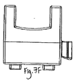
本発明のこの側面のまだ別の例では、図2A−2L、5A−5J、7A−7J、8A−8I、9A−9I、11A−11Iおよび12A−12Jのそれぞれは、独特の形状の部材のさまざまな側面を示し、それぞれの部材は5つの入口と1つの水平方向の出口を有する。これらの部材のそれぞれは異なる実施例を表しているが、すべては本発明の同じ入口/出口構成を共有する。同様に、図6A−6Iおよび10A−10Iは、独特の形状の部材のさまざまな側面を示し、各々は4つの入口と1つの水平方向の出口を有する。これは、本発明の同じ入口/出口原則に準じるさまざまな形状の別の例を表す。   In yet another example of this aspect of the invention, each of FIGS. 2A-2L, 5A-5J, 7A-7J, 8A-8I, 9A-9I, 11A-11I, and 12A-12J is a unique shaped member. Various aspects are shown, each member having five inlets and one horizontal outlet. Each of these members represents a different embodiment, but all share the same inlet / outlet configuration of the present invention. Similarly, FIGS. 6A-6I and 10A-10I show various aspects of uniquely shaped members, each having four inlets and one horizontal outlet. This represents another example of various shapes according to the same entry / exit principle of the present invention.

(ii)水平方向の部材により作成されるパスウェイ
以上のように、形状または構造に関わりなく、ほとんどのモジュール式部材は、水平方向の出口の部材と縦方向の出口の部材という2つの一般的な区分に分けることができる。前者の例は図15Bと15Cに示されており、後者の例は17B−17Eに示される。
(Ii) Pathways created by horizontal members As mentioned above, regardless of shape or structure, most modular members have two common types: horizontal outlet members and longitudinal outlet members. Can be divided into segments. The former example is shown in FIGS. 15B and 15C, and the latter example is shown in 17B-17E.

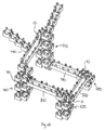
水平方向の出口部材は、別の隣の部材に接続すると、一般的に水平方向のパスウェイを作成するという共通の特徴を共有する。水平方向のパスウェイは、正確には水平方向とすることができる場合もできない場合もある。パスウェイは、下向きの傾きを含み、一般的には、部材の中心付近から部材の外側に向かって下がる。図18A、19A、20A、21Aおよび22Aは、実際の部材は示されていないが、複数の入口/出口構成を示す。また、図18B、19B、20B、21Bおよび22Bは、それぞれの入口/出口構成を達成する基本的な構成で相互接続された複数の立方体状の水平方向の出口のある部材10を示し、入口と出口をそれぞれ破線と実践で示す。各部材は、その隣の部材に比較して縦方向に二分の一の段差だけずらす。縦方向のオフセットにより、ビー球またはその他の球状物体のためのパスウェイが部材間に作成される。これらの図面は、部材間で二分の一の段差の縦方向のオフセットを示すが、その他のオフセットも本発明の原理を逸脱することなく実施できる。   A horizontal outlet member shares the common feature of creating a horizontal pathway when connected to another adjacent member. The horizontal pathway may or may not be exactly horizontal. The pathway includes a downward inclination, and generally falls from the vicinity of the center of the member toward the outside of the member. 18A, 19A, 20A, 21A, and 22A show multiple inlet / outlet configurations, although the actual members are not shown. 18B, 19B, 20B, 21B, and 22B also show a member 10 with a plurality of cubic horizontal outlets interconnected in a basic configuration that achieves the respective inlet / outlet configuration, Each exit is shown with a dashed line and practice. Each member is shifted by a half step in the longitudinal direction compared to the adjacent member. The longitudinal offset creates a pathway between the members for a bead or other spherical object. Although these drawings show a vertical offset of one-half step between members, other offsets can be implemented without departing from the principles of the present invention.

再び、図18B、19B、20B、21Bおよび22Bを参照して、以下で詳細を説明する。ここで図18Bは、十字形部材10の縦列構成を示し、図19Bは立方体状の部材20のスラローム構成を示す。図20Bは、立方体部材10のらせん構成を示す。図21Bは、立方体部材10のジグザグ構成を示す。また、図22Bは、立方体部材10の二重らせん構造を示す。図23Bを参照すると、水平方向の出口のある十字形部材50は、図19Bに類似したスラローム構成で示される。つまり、図23Bと図19Bで示される部材はどちらも、図23Aと19Aで示される同じ入口/出口構成を有する。この構成は、同じ入口/出口構成を備える独特の形状の部材を作成することができるだけでなく、同じパスウェイ構成で独特の形状の部材を接続することができることを示す。   Again, details will be described below with reference to FIGS. 18B, 19B, 20B, 21B and 22B. Here, FIG. 18B shows a tandem configuration of the cross-shaped member 10, and FIG. 19B shows a slalom configuration of the cube-shaped member 20. FIG. 20B shows the helical configuration of the cubic member 10. FIG. 21B shows a zigzag configuration of the cubic member 10. FIG. 22B shows a double helix structure of the cubic member 10. Referring to FIG. 23B, a cruciform member 50 with a horizontal outlet is shown in a slalom configuration similar to FIG. 19B. That is, both the members shown in FIGS. 23B and 19B have the same inlet / outlet configuration shown in FIGS. 23A and 19A. This configuration shows that not only can uniquely shaped members with the same inlet / outlet configuration be created, but also uniquely shaped members can be connected in the same pathway configuration.

これらの図面(図18B、19B、20B、21B、22Bおよび23B)に示されているように、部材が縦方向のオフセットで構成される場合、1つの部材の水平方向の出口は、その下で隣接する部材の入口と出合う。しかしながら、下で隣接する部材すべてが、上側にある隣接部分からの出口にかみ合う必要はない。部材は、水平方向の出口を指す下側の隣接部分への水平方向のパスウェイだけを作成する。   As shown in these drawings (FIGS. 18B, 19B, 20B, 21B, 22B and 23B), if the member is configured with a longitudinal offset, the horizontal outlet of one member is below it Meet the entrance of an adjacent member. However, it is not necessary for all the lower adjacent members to engage the outlet from the upper adjacent portion. The member only creates a horizontal pathway to the lower adjacent portion that points to the horizontal exit.

個別部材の入口/出口構成のように、同じ入口/出口システムに従うさまざまな形状や構造の部材が、配置できることも事実である。例えば、図24は、10個の部材に設計された入口/出口システムの構成を示すが、実際の部材は示されていない。図25Aは、図24に示された入口/出口システム構成に配置された10個の立方体状の部材を示すが、特定のシステムの構成を実現する1つの方法を図説している。図25Bと25Cは、それぞれ、上面と前面から見たシステム構成の立方体状の部材の実装を示す。図26A−26Cは、10個の球状部材により実現された図24に示される同じ入口/出口システムの構成を示す。従って、入口/出口システムの構成は、さまざまな異なる形状の部材により実装できること、および、構成はそれを実現するために使用される部材には依存していないことがわかる。   It is also true that members of various shapes and structures that follow the same inlet / outlet system can be placed, such as individual member inlet / outlet configurations. For example, FIG. 24 shows an inlet / outlet system configuration designed for 10 members, but the actual members are not shown. FIG. 25A shows ten cubic members arranged in the inlet / outlet system configuration shown in FIG. 24, but illustrates one way to implement a particular system configuration. FIGS. 25B and 25C show the mounting of a cubic member of the system configuration as viewed from the top and front, respectively. 26A-26C show the same inlet / outlet system configuration shown in FIG. 24 implemented with ten spherical members. Thus, it can be seen that the configuration of the inlet / outlet system can be implemented with a variety of differently shaped members and that the configuration is independent of the members used to achieve it.

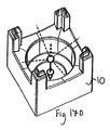
図1Fを参照すると、ビー球またはその他の球状物体は、部材の内室360(図1Aに表示)のメス接合の縦方向に配列された構成要素231(図61Bに表示)を通過して、水平方向の入口310から立方体状の部材10に入ることができる。図1Fに示される部材10の実施例では、入口で形成される部材の外側の縦方向の面との交差点の入口310は、図27Eと27Fに示されるように、U字型で、正方形に近い。図27Eを参照すると、この交差点での入口の開口部の横断面積Aは、0.2387平方インチであり、開口部の高さHは二分の一インチである。直径が二分の一インチの円は図Fの入口に示される。円の面積A’は、0.1963平方インチであり、入口の開口自体に比較的近似であり、図27Fに示されるように、入口の開口部をほとんど満たす。この場合、入口対円の面積費は1.22である。部材の外側の縦方向の面との交差点での入口の開口部の形状が正方形に近い本発明の一実施例は、図27Gと27Hに見られるように、交差点Aの入口開口部の横断面積は0.2728平方インチである。比較すると、円の面積A‘は0.1963平方インチであり、入口の開口部自体の面積に比較的近似であり、図27Hに示されるように、この場合、入口対円の面積比は1.39である。本発明の合同で拡大または縮小版が設計できる。その他の製品は、開口部が半円形の場合、図27Aおよび27Bに示される設計のような、比が2.00というはるかに大きい入口対円の面積比を提供する。入口対円の比が大きい別の可能な入口設計は、図27Cと27Dに見られ、この場合、比は2.55であり、入口はおよそ四角にできる。図27A−27Dのこれらの配列は、直径が入口の高さに等しい円には入口の開口部自体の面積よりもはるかに狭い断面積を有することを図説する。   Referring to FIG. 1F, a bead or other spherical object passes through the components 231 (shown in FIG. 61B) arranged in the longitudinal direction of the female joint of the inner chamber 360 of the member (shown in FIG. 1A), A cube-shaped member 10 can be entered from a horizontal inlet 310. In the embodiment of member 10 shown in FIG. 1F, the inlet 310 at the intersection with the outer longitudinal surface of the member formed at the inlet is U-shaped and square, as shown in FIGS. 27E and 27F. close. Referring to FIG. 27E, the cross-sectional area A of the entrance opening at this intersection is 0.2387 square inches and the opening height H is 1/2 inch. A half inch diameter circle is shown at the entrance of FIG. The area A 'of the circle is 0.1963 square inches, which is relatively close to the inlet opening itself and almost fills the inlet opening, as shown in FIG. 27F. In this case, the area cost of the entrance to the circle is 1.22. One embodiment of the present invention where the shape of the inlet opening at the intersection with the outer longitudinal surface of the member is close to a square is the cross-sectional area of the inlet opening at the intersection A, as seen in FIGS. Is 0.2728 square inches. By comparison, the area A ′ of the circle is 0.1963 square inches, which is relatively close to the area of the inlet opening itself, as shown in FIG. 27H, where the inlet to circle area ratio is 1 .39. Enlarged or reduced versions can be designed in conjunction with the present invention. Other products provide a much larger inlet-to-circle area ratio of 2.00, such as the design shown in FIGS. 27A and 27B, when the opening is semicircular. Another possible inlet design with a large inlet to circle ratio can be seen in FIGS. 27C and 27D, where the ratio is 2.55 and the inlet can be approximately square. These arrays of FIGS. 27A-27D illustrate that a circle whose diameter is equal to the height of the inlet has a cross-sectional area that is much narrower than the area of the inlet opening itself.

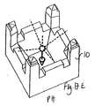
図1Fを参照すると、水平方向の入口310は、部材10の縦方向の面に形成される。2つの水平方向の出口どちらも、この水平方向の入口310のように部材の同じ縦方向の面には形成されていないので、部材の縦方向側には、この水平方向の入口310の直下に隙間がない。しかし、図1Gを参照すると、部材の別の縦方向の面が示されており、統合された開口部350が示される。統合された開口部は、この部材の縦方向側に水平方向の入口310と水平方向の出口330の両方を定義する。図1Gに示された縦方向の入口310は、図310に示される縦方向の入口310と同じ形状であるようには見えないが、どちらの縦方向の入口も同じ目的を果たし、部材の内室360への入口点を提供する。ここで、入口点は実質的に部材の上半分に形成される。従って、これらの部材は、縦方向側により水平方向の入口310を定義するが、図1Gに示されているように、水平方向の入口310の下の同じ縦方向側に水平方向の出口330があると、縦方向の入口には、図1Fに示されているように、同じ縦方向側に水平方向の出口がない場合とは異なる外見になる。それにもかかわらず、各縦方向側は、同じ側の水平方向の出口の有無にかかわらず、水平方向の入口を定義する。図1Gに見られるように統合された開口部350により定義される水平方向の入口は、部材が別の部材と結合すると、さらによく理解できる。例えば、図13Gに示された立方体状の部材は、
水平方向の入口310と水平方向の出口330両方を定義する統合された開口部350を有する。同一の部材は、ジグザグ構成で図22Bに示されている。例えば、部材Bの統合された開口部は、水平方向の入口310B(部材Aから)と水平方向の出口330B、および部材Cにつながる水平方向出口330Bの両方を定義する。
Referring to FIG. 1F, the horizontal inlet 310 is formed in the longitudinal surface of the member 10. Neither of the two horizontal outlets is formed on the same longitudinal surface of the member as the horizontal inlet 310, so the longitudinal side of the member is directly below the horizontal inlet 310. There is no gap. However, referring to FIG. 1G, another longitudinal face of the member is shown, showing an integrated opening 350. The integrated opening defines both a horizontal inlet 310 and a horizontal outlet 330 on the longitudinal side of the member. The longitudinal inlet 310 shown in FIG. 1G does not appear to be the same shape as the longitudinal inlet 310 shown in FIG. 310, but both longitudinal inlets serve the same purpose and are within the member. Provides an entry point to chamber 360. Here, the entry point is substantially formed in the upper half of the member. Thus, these members define a horizontal inlet 310 by the vertical side, but a horizontal outlet 330 is located on the same vertical side under the horizontal inlet 310 as shown in FIG. 1G. If so, the vertical inlet has a different appearance than if there is no horizontal outlet on the same vertical side, as shown in FIG. 1F. Nevertheless, each longitudinal side defines a horizontal inlet, with or without a horizontal outlet on the same side. The horizontal inlet defined by the integrated opening 350 as seen in FIG. 1G can be better understood when the member is coupled to another member. For example, the cubic member shown in FIG.
It has an integrated opening 350 that defines both a horizontal inlet 310 and a horizontal outlet 330. The same members are shown in FIG. 22B in a zigzag configuration. For example, the integrated opening of member B defines both a horizontal inlet 310B (from member A) and a horizontal outlet 330B and a horizontal outlet 330B leading to member C.

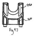
縦方向の出口がある部材に関して、これらの部材の上向きに凸面の床は、床に接触する落下球体へのなんらかの水平運動を誘導する。図4Bに見られるように、上向きの凸面の床を備える縦方向出口のある部材は、部材の内室360からの球体の縦軸を許可するために、上向き凸面の床に穴370を定義する。従って、複数の縦方向に出口のアル部材のカラムから落下する球体は、自由落下とはならず、床の存在により一部速度が減少する。時には、落下している球体は、下側が円状の出口開口となる上向き凸面の床にはまると、急速ならせん運動を得る。   For members with longitudinal exits, the upwardly convex floor of these members induces some horizontal movement to the falling sphere that contacts the floor. As seen in FIG. 4B, a member with a longitudinal outlet with an upwardly convex floor defines a hole 370 in the upwardly convex floor to allow the longitudinal axis of the sphere from the inner chamber 360 of the member. . Accordingly, the spheres falling from the plurality of columns of the outlet Al members in the vertical direction are not free-falling, and the speed is partially reduced due to the presence of the floor. Sometimes, a falling sphere gets a rapid helical motion when it falls on an upwardly convex floor with a circular outlet opening on the lower side.

(iii)縦方向の部材により作成されるパスウェイ
水平方向出口のある部材とは対照的に、縦方向出口のある部材は、縦方向に別の部材に積み重ねると、縦方向のパスウェイが作成されるという共通な特徴を共有する。図17A−17Eを参照すると、ここでも、特有の形状の部材は、この場合には、単独の縦方向出口と5つの入口という、同じ入口/出口構成を共有できるということが明らかである。これらの縦方向の出口のある部材のいずれかが別の部材の上に積み重ねられると、縦方向のパスウェイは、縦方向出口のある部材の下側に作成される。
(Iii) Pathways created by longitudinal members In contrast to members with horizontal exits, members with longitudinal exits create longitudinal pathways when stacked on top of other members in the longitudinal direction. Share the common characteristics of Referring to FIGS. 17A-17E, it is again apparent that the uniquely shaped members can in this case share the same inlet / outlet configuration, with a single longitudinal outlet and five inlets. When any of these longitudinal exit members is stacked on top of another member, a longitudinal pathway is created below the longitudinal exit member.

(iv)パスウェイの無作為性
2つ以上の水平方向の出口を備える水平方向出口部材がその他の同様な部材と接続されると、そこに作成されるパスウェイには、一定の無作為度が含まれる。ビー球のような物体がこのパスウェイ構成のパスウェイに入ると、ビー球は、以下に詳細を説明するように、一般的にはパスウェイを通って下向きに移動する。2、3、または4つの出口部材に達すると、ビー球は、出口のいずれかから出ることができる。
(Iv) Randomness of pathways When a horizontal exit member with two or more horizontal exits is connected to other similar members, the pathway created there will contain a certain degree of randomness It is. When an object such as a marble enters the pathway of this pathway configuration, the marble moves generally downward through the pathway, as will be described in detail below. When 2, 3, or 4 outlet members are reached, the bee ball can exit from any of the outlets.

例えば、図28を参照すると、ビー球が2つの出口のある立方体状部材10に、4つのらせん500のいずれかの上から入ると、ビー球がらせん500に入るか、細長い部材550に達する確率は50−50である(以下に詳細を説明)。同様に、図29を参照すると、ビー球が、追加のサポート部材を備える4つのらせん510のいずれかの上から2つの出口のある立方体部材10に入ると、ビー球がらせん510にはいるか、細長い部材550に達するかの確率は50−50である。図5.2、5.3、6.1、6.2、11.2、12.4および13.3のように、パスウェイ構成がより複雑になると、パスウェイの無作為度は本質的に増加する。2つのビー球が2つの出口ブロック内で衝突すると、それぞれのビー球は別の出口から出てくる傾向にある。   For example, referring to FIG. 28, the probability that a B-sphere will enter the helix 500 or reach the elongate member 550 when the B-sphere enters the cubic member 10 with two outlets from above any of the four helices 500. Is 50-50 (detailed below). Similarly, with reference to FIG. 29, if a bee sphere enters the cube member 10 with two outlets from above any of the four helices 510 with additional support members, is the bee sphere in the helix 510? The probability of reaching the elongated member 550 is 50-50. As pathway configurations become more complex, as shown in Figures 5.2, 5.3, 6.1, 6.2, 11.2, 12.4, and 13.3, the randomness of pathways increases inherently. To do. When two marbles collide in two exit blocks, each marble tends to come out of a different outlet.

(B.部材構造)
このように、モジュール式部材は、本発明の原則に従いながらも、さまざまな形状と構造をとることができる。本発明の可能な実施例の限定されない例には、立方体、三角形、四角形、円筒、球体、六角形、八角形、切断された8面体、双台塔(bicupolar)、および十字形または「Tプラン」を含む。上記の入口/出口の原理と縦方向のオフセットの原理どちらも、モジュール式部材の特定の形状または構造に関係なく、実現可能である。さらに、上記および以下で詳細を説明するように、同様なモジュール式部材を組み立てる場合のさまざまなパスウェイ構成も、モジュール式部材の特定の形状または構造に関係なく、実現可能である。
(B. Member structure)
As such, the modular member can take a variety of shapes and configurations while still following the principles of the present invention. Non-limiting examples of possible embodiments of the present invention include cubes, triangles, squares, cylinders, spheres, hexagons, octagons, cut octahedrons, bipolars, and cruciforms or “T-plans” "including. Both the inlet / outlet principle and the longitudinal offset principle described above are feasible regardless of the particular shape or structure of the modular member. Furthermore, as will be described in detail above and below, various pathway configurations for assembling similar modular members are possible regardless of the particular shape or structure of the modular members.

(C.接合具)
(i)接合の一般的属性
同様な部材は、一般的に、接合システムにより、お互いに組立および連結される。このように、さまざまな接合システムと実施例は、望ましい組立および連結効果を達成するために、最適にすることができ、それぞれ、固有の特徴を有する。
(C. Joiner)
(I) General attributes of joining Similar members are typically assembled and connected to each other by a joining system. In this way, the various joining systems and embodiments can be optimized to achieve the desired assembly and coupling effects, each with its own characteristics.

例えば、L接合またはU接合は、以下で詳細に説明するが、一般的に、ある部材を隣の部材に縦方向にスライドすることにより部材が組み立てられる場合、スライド式組立を提供する。部材は、接合のL字形部分により、少なくとも部分的に連結される。あるいは、摩擦接合は、以下で詳細を説明するが、ある部材を隣の部材に縦方向または水平方向にスライドすることにより組み立てる部材を提供する。摩擦接合部坐位は、少なくとも部分的に、接合部分の摩擦力により、連結される。これらやその他の接合タイプは以下で詳細を説明する。   For example, an L-junction or U-junction is described in detail below, but generally provides a sliding assembly when a member is assembled by sliding one member longitudinally to an adjacent member. The members are at least partially connected by an L-shaped portion of the joint. Alternatively, friction bonding, which will be described in detail below, provides a member that is assembled by sliding one member longitudinally or horizontally to an adjacent member. The friction joint sitting position is at least partially connected by the frictional force of the joint portion. These and other joint types are described in detail below.

接合の別の側面は、2つの部材が相互接続される場合の構成である。接合により、二分の一の段差の縦方向のオフセットが確保され、隣の部材との適切なパスウェイ配置を提供する。   Another side of the joint is the configuration when the two members are interconnected. The joining ensures a vertical offset of one-half step and provides an appropriate pathway arrangement with the adjacent member.

第一の分割接合タイプの特定の例では、以下で詳細が説明されるが、図30A−30Dは、立方体状のモジュール式部材10のこの接合を示す。これらの図面に見られるように、オス接合200は、部材の縦方向面210の外側に突出している2つの縦方向に配置された部材201を含み、水平方向出口のいずれかの側に、部材の下部分が配置される。立方体状の部材は、一般的に、各水平方向の出口に1つのオス接合を有する。このように、図30A−30Dでは、部材は、1つの水平方向の出口と1つのオス接合を有する。   In the specific example of the first split junction type, details are described below, but FIGS. 30A-30D illustrate this junction of the cubic modular member 10. As can be seen in these drawings, the male joint 200 includes two longitudinally disposed members 201 projecting outwardly of the longitudinal surface 210 of the member, and on either side of the horizontal outlet, the member The lower part is arranged. Cubic members typically have one male junction at each horizontal outlet. Thus, in FIGS. 30A-30D, the member has one horizontal outlet and one male joint.

縦方向出口の立方体状部材は、一般的に、側面にオス接合を有することはない。これらの立方体状部材のそれぞれは、縦方向のサポート部材40の内側230により定義される、4つのメス接合も含む。これらのメス接合は、オス接合を受け止めて連結するように構成される。   Cubic members at the longitudinal exit generally do not have a male joint on the side. Each of these cubic members also includes four female joints defined by the inner side 230 of the longitudinal support member 40. These female joints are configured to receive and connect male joints.

本発明の一実施例では、モジュール式部材は接合具を一切含まない。この実施例では、部材は、望ましい場所に実質的に平らな表面の上にモジュール式部材を置くことにより組み立てられる。二分の一の段差の縦方向のオフセットは、接合システムがない場合でも、いくつかの手段により依然として実現することができる。例えば、一連のオフセット部材(非表示)を提供することができる。オフセット部材は、高さがその他の部材の高さのおよそ半分であることを除けば、その他のモジュール式部材の寸法と実質的に類似した寸法にすることができる。一定の形状の部材をオフセット部材の上に積み重ねることにより、一定の形状の部材は、オフセット部材の上に積み重ねない隣の部材に比較すると、適切な縦方向のオフセットに配置される。オフセット部材を格子状のような希望の配置に構成することにより、残りのモジュール式部材を配置して、上記のパスウェイを作成するように構成することができる。   In one embodiment of the invention, the modular member does not include any connector. In this embodiment, the members are assembled by placing the modular member on a substantially flat surface at the desired location. The longitudinal offset of the half step can still be achieved by several means, even without a joining system. For example, a series of offset members (not shown) can be provided. The offset member can be sized substantially similar to the dimensions of the other modular members, except that the height is approximately half the height of the other members. By stacking a constant shape member on top of the offset member, the constant shape member is placed at an appropriate longitudinal offset as compared to an adjacent member that does not stack on the offset member. By configuring the offset member in a desired arrangement such as a lattice, the remaining modular members can be arranged to create the pathway described above.

(ii)接合例
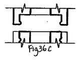
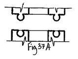
上記のように、本発明に従って、さまざまな接合を使用することができる。このような適切な接合の無限の例が、図33A−33B、34A−34D、35A−35C、36A−36D、37A−37C、38A−38Cおよび39に示されているが、それぞれ、2つのモジュール式部材の接合部分を図説する。これらの図面のそれぞれには、オス接合が上方の位置に示され、メス接合が下方の位置に示されている。
(Ii) Joining Examples As mentioned above, various joinings can be used in accordance with the present invention. An endless example of such a suitable junction is shown in FIGS. 33A-33B, 34A-34D, 35A-35C, 36A-36D, 37A-37C, 38A-38C and 39, respectively, but with two modules The joint part of a formula member is illustrated. In each of these drawings, the male joint is shown in the upper position and the female joint is shown in the lower position.

図33A−33B、35A−35Cおよび37A−37Cに示された接合タイプは、縦方向組立接合であり、図34A−34D、36A−36D、38A−38Cおよび39に示された接合タイプは、水平方向/縦方向組立接合である。以下に詳細を説明するように、縦方向組立および水平方向/縦方向組立は、一般的に、オスとメスの接合を組み立てて、モジュール式部材を連結する様式を説明するものである。縦方向組立とは、1つのモジュール式部材のオス接合を下にスライドして、別の部材のメス接合に入れることにより、部材が連結されることを指す。水平方向/縦方向組立とは、縦方向組立と同様にして縦方向に、あるいは、1つのモジュール式部材のオス接合を水平方向にスライドして別の部材のメス接合に入れることにより、部材を連結できることを指す。組立過程をここで詳細に説明する。   The joint types shown in FIGS. 33A-33B, 35A-35C and 37A-37C are longitudinal assembly joints, and the joint types shown in FIGS. 34A-34D, 36A-36D, 38A-38C and 39 are horizontal. Direction / longitudinal assembly joint. As described in detail below, longitudinal assembly and horizontal / longitudinal assembly generally describe the manner in which male and female joints are assembled to connect modular members. Longitudinal assembly refers to connecting members by sliding a male joint of one modular member down into a female joint of another member. Horizontal / longitudinal assembly is the same as longitudinal assembly in the longitudinal direction or by sliding the male joint of one modular member horizontally into the female joint of another member. It means that it can be connected. The assembly process will now be described in detail.

以下で説明する縦方向組立接合の利点は、強度が増すことと、これによりサポートが提供されることである。縦方向の組立接合のある部材は、お互いに容易かつ安全に連結されて、適切なパスウェイが配置されるとともに縦方向のオフセットが確保される。以下で説明する水平方向の組立接合の利点は、組み立てられた部材の配列から、部材を追加および排除できることである。水平方向/縦方向組立接合部坐位は、水平方向に連結および分解できるので、そうでなければ隣の部材により縦方向に固定されることになる部材を取り除くために分解する必要がない。   The advantages of the longitudinal assembly described below are increased strength and thus provide support. Members with longitudinal assembly are easily and safely connected to each other so that an appropriate pathway is placed and a vertical offset is ensured. An advantage of the horizontal assembly connection described below is that members can be added and removed from the assembled array of members. The horizontal / longitudinal assembly joint sitting position can be connected and disassembled in the horizontal direction so that it does not need to be disassembled to remove a member that would otherwise be secured in the longitudinal direction by an adjacent member.

分割接合タイプ1:第一の分割接合タイプの例は、33A−33Bおよび34A−34Dに示される。この接合タイプは、その部材の水平方向の出口パスウェイ部分を形成するオス接合により特徴づけられる。このオス接合を通過するビー球は、オス接合を形成する反対側の縦方向に配置された部材の間を直接通過する。図33Aは、V字型の接合を図説し、図33BはL字型接合を図説するが、どちらも縦方向組立である。オスのV字型接合の拡大構成とオスのL接合のLフックが部材を固定する。図34Aは、摩擦接合を図説しており、部材は摩擦力により固定される。図34Bと34Cは、スナップ式1の接合を図説するが、水平方向組立の間後ろに曲がるオス接合の端にある突起が、メス接合の受け取り側収納部に入る。図34Dは、スナップ式タイプ2接合を図説するが、オス接合の中間にある突起が、メス接合の受け取り側収納部に入る。摩擦接合とスナップ式接合のどちらも、水平方向/縦方向組立が可能である。   Split Junction Type 1: Examples of the first split junction type are shown in 33A-33B and 34A-34D. This joint type is characterized by a male joint that forms the horizontal exit pathway portion of the member. The bee sphere passing through the male joint passes directly between members arranged in the opposite longitudinal direction forming the male joint. FIG. 33A illustrates a V-shaped joint and FIG. 33B illustrates an L-shaped joint, both of which are longitudinal assemblies. An enlarged configuration of the male V-shaped joint and an L hook of the male L joint secure the member. FIG. 34A illustrates friction welding, where the members are fixed by frictional forces. FIGS. 34B and 34C illustrate the snap 1 joint, but a protrusion at the end of the male joint that bends back during horizontal assembly enters the receiving housing of the female joint. FIG. 34D illustrates a snap-type type 2 joint, but the protrusion in the middle of the male joint enters the receptacle housing for the female joint. Both friction and snap joints can be assembled horizontally / vertically.

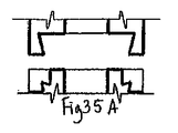
分割接合タイプ2:第二の分割接合タイプの例は、35A−35Cおよび36A−36Dに示される。この接合タイプは、モジュール式部材の外側に形成されているオス接合と、部材の水平方向出口パスウェイ部分を形成するメス接合により特徴付けられる。図35Aと35Bは、オスのV字接合の拡大構成が部材を固定している場合のV字接合を図説する。図35Aに示された実施例は、隣接のメス接合を含むので、上方の隣接ブロックをどの側面からでも取り付けることができる。図35Bに示される実施例は、隣接のオス接合が不可能なので、ブロックはどの側面からも取り付けることができない。図35Cは、L接合を図説しており、メスL接合のLフックが部材を固定する。V字型接合とL接合のどちらも、縦方向の組立接合である。図36Aは、摩擦接合を図説しており、部材は摩擦力により固定される。図36Bと36Cは、スナップ式タイプ1接合を図説しており、図36Dはスナップ式タイプ2接合を図説する。摩擦接合とスナップ式接合のどちらも、水平方向/縦方向組立が可能である。   Split junction type 2: Examples of the second split junction type are shown in 35A-35C and 36A-36D. This type of joint is characterized by a male joint formed on the outside of the modular member and a female joint that forms the horizontal exit pathway portion of the member. FIGS. 35A and 35B illustrate a V-joint when the enlarged configuration of the male V-joint secures the member. The embodiment shown in FIG. 35A includes adjacent female joints so that the upper adjacent block can be attached from any side. The embodiment shown in FIG. 35B does not allow adjacent male joints, so the block cannot be attached from any side. FIG. 35C illustrates the L-junction, and the L hook of the female L-junction fixes the member. Both the V-shaped joint and the L joint are assembly joints in the vertical direction. FIG. 36A illustrates friction welding, where the members are fixed by frictional forces. 36B and 36C illustrate a snap type 1 joint and FIG. 36D illustrates a snap type 2 joint. Both friction and snap joints can be assembled horizontally / vertically.

二重接合:二重接合タイプの例は図37A−37Cおよび38A−38Cに示される。この接合タイプは、2つの別の接合によって特徴付けられる。オス接合を形成する2つの縦方向に配置された部材のそれぞれは、図37A−37Cおよび38A−38Cに見られるように、それぞれの側の中間にある。この構成は、オス接合が内側にある場合(分割接合タイプ1)または外側にある場合(分割接合タイプ2)とは区別される。図37Aは、二重接合の円筒状の実施例を図説する。図37Bは、二重接合のV字型実施例を図説し、図37Cは、二重接合のL接合実施例を図説する。これらの実施例のそれぞれは、縦方向組立である。図38Aは、摩擦接合実施例を図説し、図38Bと38Cはスナップ式実施例を図説するが、これらすべては水平方向/縦方向組立である。   Double Junction: Examples of double junction types are shown in FIGS. 37A-37C and 38A-38C. This junction type is characterized by two separate junctions. Each of the two longitudinally arranged members forming the male joint is in the middle of each side, as seen in FIGS. 37A-37C and 38A-38C. This configuration is distinguished from the case where the male joint is inside (split joint type 1) or the outside (split joint type 2). FIG. 37A illustrates a double bonded cylindrical embodiment. FIG. 37B illustrates a double junction V-shaped embodiment, and FIG. 37C illustrates a double junction L-junction embodiment. Each of these embodiments is a longitudinal assembly. FIG. 38A illustrates a friction welding embodiment and FIGS. 38B and 38C illustrate a snap-on embodiment, all of which are horizontal / longitudinal assemblies.

磁磁石接合:図39は、磁石接合を図説するが、反対極の磁石またはヒンジ式の回転磁石が、Xで示すように、オス接合とメス接合に取り付けられている。磁力が部材を固定する。オス接合からのびる突起乳頭は、メス接合の対応する収納部により受け止められるので、適切な配列が実現したことが示される。乳頭と収納部は、2つの部材を固定化する場合に磁力を補完することもできる。   Magnetomagnet Bonding: FIG. 39 illustrates magnet bonding, but opposite pole magnets or hinged rotating magnets, as indicated by X, are attached to the male and female joints. Magnetic force fixes the member. Since the protruding nipple extending from the male joint is received by the corresponding storage part of the female joint, it is shown that an appropriate arrangement has been realized. The nipple and the storage part can also complement the magnetic force when the two members are fixed.

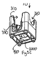
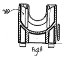
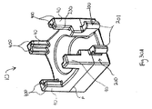
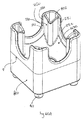
U接合:U字形接合の一実施例が、図32A−32Fの立方体状の部材10上に示される。U字形接合は、オスのU接合200とメスのU接合230を備える。これらの図面に見られるように、オスのU接合200は、湾曲部202(図32Aを参照)、部材の縦方向面の外側の突起210(図32Fを参照)により接続された2つの縦方向に配列された部材201を含み、水平方向出口の側面と底を取り囲む部材の下方部分に位置する(図32Dを参照)。図32Aと61Aに見られるように、この実施例のオスのU接合は、さらに、2つの伸びている三角形203を定義するので、オスのU接合の下方部分は四角のような外観になる。図32Aと61Aに見られるように、メスのU接合230は、2つの縦方向に配列された部材231を含み、縦方向のサポート部材40により定義され、湾曲部分232により接合される。メスのU字接合230は、オスのU接合200を受け取り連結するように構成される。図1A、1Cおよび1Fは、水平方向入口310の開口部周辺に形成されるメス接合を示しており、これは、オスのU字接合と連結する。   U-junction: One example of a U-shaped joint is shown on the cubic member 10 of FIGS. 32A-32F. The U-shaped joint comprises a male U-junction 200 and a female U-junction 230. As can be seen in these drawings, the male U-junction 200 has two longitudinal directions connected by a curved portion 202 (see FIG. 32A) and a protrusion 210 (see FIG. 32F) outside the longitudinal surface of the member. And is located in the lower part of the member surrounding the side and bottom of the horizontal outlet (see FIG. 32D). As seen in FIGS. 32A and 61A, the male U-junction in this example further defines two elongated triangles 203 so that the lower portion of the male U-junction looks like a square. As seen in FIGS. 32A and 61A, the female U-joint 230 includes two longitudinally arranged members 231, defined by the longitudinal support member 40 and joined by a curved portion 232. Female U-junction 230 is configured to receive and connect male U-junction 200. 1A, 1C and 1F show a female joint formed around the opening of the horizontal inlet 310, which connects with a male U-junction.

「フックとループ」接合:「フックとループ」接合(非表示)は、連結されるモジュール式部材の向き合う側に、Velcroのようなフックとループのファスナー素材を実装する。素材は、上記の磁石接合の磁石と同様な位置または、部材の連結に適切なその他の場所に位置することができる。   "Hook and loop" joint: A "hook and loop" joint (not shown) implements hook and loop fastener material, such as Velcro, on opposite sides of the modular members to be joined. The material can be located in the same position as the magnet-joined magnet described above or in other locations suitable for connecting the members.

接着接合:接着接合(非表示)も、隣接のモジュール式部材と連結するために、適切な場所である量の接着剤を適用することにより、実装できる。永久接着剤、半接着剤、および水溶性のりなどの非永久接着剤など、この目的には、さまざまな接着剤が適している。さらに、モジュール式部材が、以下に詳細を説明するように、接合は氷から形成される場合、接合は、操作されて凍結することができる解ける物質にでき、2つの部材を接着する。   Adhesive bonding: Adhesive bonding (not shown) can also be implemented by applying an appropriate amount of adhesive to connect to adjacent modular members. A variety of adhesives are suitable for this purpose, including permanent adhesives, semi-adhesives, and non-permanent adhesives such as water soluble glues. Further, if the modular member is formed from ice, as will be described in detail below, the bond can be an unraveling material that can be manipulated and frozen to bond the two members together.

(iii)縦方向の接合
上記の接合システムは、同様な部材を水平方向に連結する「水平方向接合」に関連する。さらに、部材は、図40Bに見られるように、1つの部材を別の部材の上に積み重ねる場合に、同様な部材を縦方向に連結するための縦方向の接合も含むことができる。すべての部材の土台には、その下にくぼみを有することができるので、土台は、接続のメス部分として機能する。あるいは、すべての部材の土台には、突起を有することができるので、土台は、接続のオス部分として機能する。また、オスとメス同体の接合も利用することができ、部材の上下はそれぞれ、オスとメスの構成要素の組み合わせを有する。これらの構成の詳細を以下に説明する。
(Iii) Longitudinal Joining The joining system described above relates to “horizontal joining” that connects similar members in the horizontal direction. In addition, the members can also include a longitudinal joint to connect similar members in the longitudinal direction when one member is stacked on top of another as seen in FIG. 40B. Since the base of all members can have a recess beneath it, the base functions as a female part of the connection. Alternatively, since the base of all members can have protrusions, the base functions as a male part of the connection. Moreover, the joint of a male and a female same body can also be utilized, and the upper and lower sides of the member have a combination of male and female components, respectively. Details of these configurations will be described below.

図30A−30Dに示される実施例では、球体状部材10の縦方向サポート部材40は、それぞれ、L字形の収納部である、縦方向のメス接合400を定義する。この実施例では、部材は、部材の下側60から突起する4つの縦方向のオス接合410も備える。縦方向のメス接合400は、別の部材の縦方向のオス接合410を受け入れるように構成され、設計されるので、部材が確実に積み重ねられるようになる。縦方向のメス接合400と縦方向のオス接合410は、図30A−30Dに見られるように、2つの部材を簡単に縦方向に組み立てることができる斜面を備える。   In the example shown in FIGS. 30A-30D, the longitudinal support members 40 of the spherical member 10 each define a longitudinal female joint 400 that is an L-shaped storage. In this example, the member also includes four longitudinal male joints 410 that project from the lower side 60 of the member. Longitudinal female joint 400 is configured and designed to receive another member's longitudinal male joint 410, thus ensuring that the members are stacked. The longitudinal female joint 400 and the longitudinal male joint 410 comprise ramps that allow the two members to be easily assembled in the longitudinal direction, as seen in FIGS. 30A-30D.

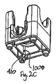
図31A−2027Dに見られる別の実施例では、縦方向のオス接合は、縦方向のサポート部材40の上端に形成されて、メスの縦方向の接合は下側60に形成される。この実施例は、各モジュール式部材は、各縦方向のサポート部材40の上に突起しているコネクタである、縦方向のオス接合50を定義する。各モジュール式部材は、さらに、下側60に4つのメスの縦方向のコネクタ100を定義し、別の部材の縦方向のオス接合50を受け入れるように構成されて設計されるので、部材を確実に積み重ねることができる。縦方向のオス接合50と縦方向のメス接合100は、図31A−2027Dに見られるように、2つの部材を簡単に縦方向に組み立てることができる斜面を備える。図31A−2027Dに見られる実施例では、タイプ2の分割接合を含むが、縦方向のオス接合50は、たこ形の突起であり、縦方向のメス接合は同じ形状の収納部である。   In another embodiment seen in FIGS. 31A-2027D, a longitudinal male joint is formed at the upper end of the longitudinal support member 40 and a female longitudinal joint is formed on the lower side 60. In this embodiment, each modular member defines a vertical male joint 50, which is a connector protruding on each vertical support member 40. Each modular member further defines four female longitudinal connectors 100 on the lower side 60 and is configured and designed to accept a longitudinal male joint 50 of another member so that the member is secured. Can be stacked. The vertical male joint 50 and the vertical female joint 100 comprise slopes that allow the two members to be easily assembled in the vertical direction, as seen in FIGS. 31A-2027D. In the example seen in FIGS. 31A-2027D, including type 2 split joints, the vertical male joint 50 is a tako-shaped protrusion and the vertical female joint is a storage part of the same shape.

図32A−32Fに示される実施例では、球体状部材10の縦方向サポート部材40は、それぞれ、そこに形成された収納部である、縦方向のメス接合400を定義する。この実施例では、部材は、部材の下側60から突起する4つの縦方向のオス接合410も備える。縦方向のメス接合400は、縦方向のオス接合410を受け入れるように構成され、設計されるので、部材が確実に積み重ねられるようになる。縦方向のメス接合400と縦方向のオス接合410は、お互いに細くなるので、2つの部材の縦方向の組立が簡単になるとともに、2つの部材の摩擦接合を確保することができる。   In the embodiment shown in FIGS. 32A-32F, the longitudinal support members 40 of the spherical member 10 each define a longitudinal female joint 400, which is a storage portion formed therein. In this example, the member also includes four longitudinal male joints 410 that project from the lower side 60 of the member. The longitudinal female joint 400 is configured and designed to receive the longitudinal male joint 410, thus ensuring that the members are stacked. Since the vertical female joint 400 and the vertical male joint 410 are thinned from each other, the vertical assembly of the two members is simplified, and the frictional connection between the two members can be ensured.

図13A−13J、18B、19B、20B、21Bおよび22Bに見られるようなその他の実施例では、タイプ1の分割接合を含むが、縦方向のオス接合は、各縦方向のサポート部材40の上に構成された先細のL字型の突起にすることができる。この実施例では、縦方向のメス接合は、図13A−13Jに見られるように、四角形の周辺により、下側60に形成される。この周辺の角内側は、メス接合を形成し、別の部材のL字形の縦方向のオス接合を受け入れるように構成され、設計される。オス接合のL字形の突起は、図13A−13Jに見られるように、Lの両端で先が細くなり、縦方向のオス接合が別の部材の縦方向のメス接合へと導入する。この構成により、2つの部材の縦方向の積み重なりが促進される。   Other embodiments, such as those seen in FIGS. 13A-13J, 18B, 19B, 20B, 21B and 22B, include type 1 split joints, but the vertical male joints are above each longitudinal support member 40. It can be made into the taper L-shaped protrusion comprised. In this embodiment, the longitudinal female joint is formed on the lower side 60 by a square perimeter, as seen in FIGS. 13A-13J. The peripheral corner inside is configured and designed to form a female joint and accept another member's L-shaped longitudinal male joint. As seen in FIGS. 13A-13J, the male joint L-shaped protrusion tapers at both ends of L, and the vertical male joint introduces into the vertical female joint of another member. This configuration promotes the vertical stacking of the two members.

(iv)組立
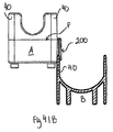
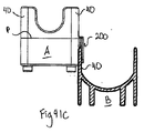
2つの部材AとBの組立の過程を示す図41A−41Dを参照すると、縦方向のサポート部材40は、メス接合230を形成し、製造中に、分割線の上の型からの削除を促進する抜き勾配で先が細くなる。オス接合200も、縦方向に配置された部材201と湾曲部分202から形成されるが、分割線の下の型から削除を促進する抜き勾配で先が細くなる。この先細りにより、オス接合は、メス接合の縦方向に配置された部材231により受け入れることができる。分割線の上下の、オスとメス部分の補完抜き勾配により、これらのオスとメスの部分は、同一平面上にある表面上に入れ子にすることができる。メス接合の先細りにより、2つ以上のモジュール式部材の組立が簡単になり、あるいは、以下に説明するように、1つの部材を4つのその他の同様な部材に入れ子にする場合でも、組立が簡単になる。図42Aと42Bは、それぞれ、図41Bと41Dの詳細を示す。
(Iv) Assembly Referring to FIGS. 41A-41D which show the process of assembling two members A and B, the longitudinal support member 40 forms a female joint 230 and, during manufacture, from the mold above the dividing line. Tapered with a draft that facilitates removal. The male joint 200 is also formed from a member 201 and a curved portion 202 arranged in the vertical direction, but tapers with a draft that facilitates removal from the mold below the parting line. Due to this taper, the male joint can be received by the member 231 arranged in the longitudinal direction of the female joint. Due to the complementary draft of the male and female parts above and below the dividing line, these male and female parts can be nested on a coplanar surface. The taper of the female joint simplifies the assembly of two or more modular members, or even when one member is nested in four other similar members as described below become. 42A and 42B show details of FIGS. 41B and 41D, respectively.

図30A−30Dおよび32A−32Fに示される実施例を参照すると、分割線Pは、部材の製造に使用された型の半分の間の分割線を示す。この実施例では、部材は、射出成形により形成されるが、その他さまざまな製造技術の詳細を以下に説明する。先細りは、部分的に、部品を型から外しやすくする抜き勾配を提供する技術的製造の利点による。また、先細りは、組立も促進する。図32A−32Fに示されるU字接合実施例を参照すると、分割線は、典型的に立方体の底の端にそって配置される。図41A−41Bおよび42A−42Bに示される実施例では、分割線Pは、およそ、オス接合の平坦な上面Tに配置される。この実施例では、この構成は、分割P線を、立方体の中心線のおよそ1/32インチから1/8インチ下に配置する。組立の利点は、部材が組み立てられている図41Aから図41Dに見られる。部材が完全に連結されると、ぴったり合うことも示される。戦略的な分割線の配置の製造技術が、部分的に、接合システムのこの機能性を作り出す。   Referring to the examples shown in FIGS. 30A-30D and 32A-32F, the dividing line P shows the dividing line between the halves of the mold used to manufacture the part. In this embodiment, the member is formed by injection molding, and details of various other manufacturing techniques are described below. Tapering is due, in part, to the advantages of technical manufacturing that provides a draft that facilitates removal of the part from the mold. Tapering also facilitates assembly. Referring to the U-junction example shown in FIGS. 32A-32F, the dividing line is typically placed along the bottom edge of the cube. In the example shown in FIGS. 41A-41B and 42A-42B, the dividing line P is approximately located on the flat top surface T of the male junction. In this embodiment, this configuration places the split P-line approximately 1/32 inch to 1/8 inch below the center line of the cube. The advantages of assembly can be seen in FIGS. 41A-41D where the members are assembled. It also shows a snug fit when the members are fully connected. Strategic dividing line placement manufacturing technology, in part, creates this functionality of the bonding system.

図42Aおよび42Bに示されるように、縦方向サポート部材40のメス接合230の半分の断面が示される。この部材の分割線の上に、縦方向のサポート部材の側面は、その間の入口に向かって内側に細くなり、分割線から遠ざかるに連れて薄くなる。補完的なやり方で、隣の部材のオス接合が示され、内側Sは同じ角度で外側に細くなる。2つのずらされたブロックの補完的角度は、組み立て中に別のブロックと合うので、複数のブロック建築の全体的な縦方向および/または直角配置を維持する。ブロックの中心線からの分割線のわずかなオフセットは、追加で、図46A−Gに示される組立過程の場合のように、システムにわずかな許容を作成する機能を果たす。数千分の一のインチのこの許容により、組立と分解を容易にする。   As shown in FIGS. 42A and 42B, a half cross section of the female joint 230 of the longitudinal support member 40 is shown. Above the parting line of this member, the side surface of the longitudinal support member becomes thinner inward toward the entrance between them, and becomes thinner as it moves away from the parting line. In a complementary manner, the male joint of the adjacent member is shown, and the inner side S narrows outward at the same angle. The complementary angle of the two offset blocks matches another block during assembly, thus maintaining the overall longitudinal and / or perpendicular orientation of the multiple block architecture. The slight offset of the dividing line from the block centerline additionally serves to create a slight tolerance in the system, as in the assembly process shown in FIGS. 46A-G. This tolerance of a thousandth of an inch facilitates assembly and disassembly.

縦方向の接合システムに提供された先細りは、特に、L接合は、分割線の特定の配置に対して、さらに利点となる。各ブロックの上半分にある縦方向のメス部材は、内側に細くなる(1/4から1 1/2度)外面と、外側に細くなる(同じ1/4から1 1/2度)内面を有する。分割線は、オス接合と合うと、図42Aに見られるように、Lの先に到達するまで、オス接合の上端周囲まで続く。そして、分割線は、Lのこの先に沿って、オス接合の底まで伸び、反対側の対応するオス接合に合うまで、出口パスウェイの端まで続く。その後、分割線は、この第二のオス接合の底にそって、Lの先まで伸び、Lからオス接合の上の平坦な端まで続き、ブロックの本体に再び出合うまで、オス接合の端に沿って伸びる。すると、オス接合は、メス接合のテーパーを完全に補完するテーパーを有することになる。2つのブロックが、縦方向に接続されると、オス接合の比較的広い開口部は、メス接合の比較的細い先を受け入れる。2つのブロックがいっしょにスライドすると、オスとメス接合の内向きと外向きに細くなる面は、2つのブロックがお互いに確実に取り付けられるまで、どんどん締め付けられる。   The taper provided in the longitudinal joining system, in particular the L joint, is an additional advantage over the particular arrangement of the parting lines. The vertical female member in the upper half of each block has an outer surface that narrows inward (1/4 to 11/2 degrees) and an inner surface that narrows outward (same 1/4 to 11/2 degrees). Have. When the dividing line is mated with the male junction, it continues to the periphery of the upper end of the male junction until it reaches the tip of L, as seen in FIG. 42A. The dividing line then extends along the tip of L to the bottom of the male junction and continues to the end of the exit pathway until it meets the corresponding male junction on the opposite side. The dividing line then extends along the bottom of this second male joint to the tip of L, continues from L to the flat end above the male joint, at the end of the male joint until it meets the block body again. Stretches along. The male joint then has a taper that completely complements the taper of the female joint. When the two blocks are connected longitudinally, the relatively wide opening of the male joint accepts the relatively narrow tip of the female joint. As the two blocks slide together, the male and female joint's inwardly and outwardly narrowing surfaces are tightened until the two blocks are securely attached to each other.

オスとメスという区別は、オス接合の2つの部分、縦方向に配置された部材200が、メスの開口部へのオス挿入としていっしょに機能するので、なくなり始めるが、オス接合の1部分だけを見ると、下から先細りになったオスを受け入れるメス接合のようにも機能する。立方体状部材の別の側面では、底の4つの隅は、先細りで丸くなるので、4つのその他の立方体状の部材に縦方向に組み立てられている立方体状の部材のような全体は、つまり、図47Aと47Bに示される構造の中心の一番上の部材などは、メス接合、つまり、4つの受け止め部材、により受け止められているオス接合として機能する。   The distinction between male and female begins to disappear because the two parts of the male joint, the vertically arranged member 200, work together as a male insertion into the female opening, but only one part of the male joint When viewed, it also functions as a female joint that accepts a male tapering from the bottom. On another side of the cubic member, the four corners of the bottom are tapered and rounded, so the whole cube-like member assembled vertically into four other cubic members, The uppermost member at the center of the structure shown in FIGS. 47A and 47B functions as a female joint, that is, a male joint received by four receiving members.

図1A−1L、2A−2L、3A−3L、4A−4Lおよび32A−32Fに見られるU字接合の実施例では、全体の接合具は、一緒になって部材を固定し、そうでなければ、分解または固定部材を緩めることができる方向の部材からの力に抵抗するためにも機能する。図43と44を参照すると、部材Aは、下から、第二の部材Bに、部材の縦方向の接合具(オスの縦方向接合410とメスの縦方向の接合400、それぞれ図44Bに表示)によって、固定することができ、同時に、第三の部材Cを部材の水平方向の接合具で固定することができる。図43−45は、部材AのオスのU字接合200のふち390を図説し、ふち390は、オス接合の縦方向に配列された部材201に沿って形成される縦方向配列部分391と、オス接合の湾曲部分203に素って形成される湾曲部分392の両方を含む。特に43Aを参照すると、部材AのオスのU時節号200のふち390の湾曲部分392は、部材CのメスのU字接合230の補完的湾曲部分232上に固定される。図45は、部材CのメスのU字接合230の補完的形状の縦方向部分231の周囲で固定された部材AのオスのU字接合200のふち390の縦方向配列部分391を示す(図45Aと45Bを参照)。ふち390は、L字接合とU字接合の間の共有機能であり、2つの部材がねじり力に抵抗するようにさせる。オスのU字接合のふち390は縦方向配列部分391と接続している湾曲部分392の両方を含むが、分割U字接合は2つの縦方向配列部分391だけを含む。図44は、部材Cの水平方向の入口で部材CのメスのU字接合230の上にぴったり固定し、縦方向リブ720(図43に表示)に接触している部材AのオスのU字接合200上のふち390を図説するが、部材Cは2つの向き合う水平方向出口を有する。この構成では、部材AとCの組み立て中、CのオスのU字接合200は、部材CのメスのU字接合230と、特に、湾曲部分232が、組み立て中、部材Aの「停止部」として機能するように、寸法的に補完する部材CのメスのU字接合230と衝突する。図61に示されるように、部材が、同じ縦方向面で入口と出口両方を定義する場合、メスのU字接合の湾曲部分232の全体は、メス接合は湾曲部分の断片を含むことができるが、存在することができない。この場合、図61Aに見られるように、上からそこに固定されている別の部材のための停止部として機能し、図61Cに見られるように、その部材の下側801に衝突するのは、オスのU字接合204の上であり、ブロックの下向き運動で終わり、適切なブロック配列を設定する。   In the examples of U-joints seen in FIGS. 1A-1L, 2A-2L, 3A-3L, 4A-4L and 32A-32F, the entire joiner together secures the member, otherwise It also functions to resist forces from members in a direction that can disassemble or loosen the fixing member. Referring to FIGS. 43 and 44, the member A is shown in FIG. 44B from the bottom to the second member B, the longitudinal connector of the member (the male longitudinal joint 410 and the female longitudinal joint 400, respectively. ), And at the same time, the third member C can be fixed with the horizontal connector of the member. 43-45 illustrates the edge 390 of the male U-junction 200 of member A, the edge 390 comprising a longitudinal array portion 391 formed along the members 201 arranged in the longitudinal direction of the male joint; It includes both curved portions 392 that are formed from the curved portion 203 of the male joint. Referring specifically to 43A, the curved portion 392 of the lip 390 of the male U time symbol 200 of member A is secured on the complementary curved portion 232 of the female U-junction 230 of member C. FIG. 45 shows a longitudinal array portion 391 of the edge 390 of the male U-joint 200 of member A secured around the complementary longitudinal portion 231 of the female U-joint 230 of member C (FIG. 45). 45A and 45B). The edge 390 is a shared function between the L-shaped joint and the U-shaped joint, and allows the two members to resist torsional force. The male U-junction edge 390 includes both a longitudinal array portion 391 and a curved portion 392 connected thereto, while a split U-joint includes only two longitudinal array portions 391. FIG. 44 shows the male U-shape of member A snugly fixed over the female U-junction 230 of member C at the horizontal inlet of member C and contacting the longitudinal rib 720 (shown in FIG. 43). Illustrating a rim 390 on the joint 200, member C has two opposing horizontal outlets. In this configuration, during the assembly of members A and C, the male U-joint 200 of C is the female U-joint 230 of member C, and in particular, the curved portion 232 is the “stop” of member A during assembly. To collide with the female U-shaped joint 230 of the member C that complements the dimension. As shown in FIG. 61, if the member defines both an inlet and an outlet in the same longitudinal plane, the entire curved portion 232 of the female U-junction can include a fragment of the curved portion. But can't exist. In this case, as seen in FIG. 61A, it acts as a stop for another member secured to it from above, and as seen in FIG. 61C, it collides with the lower side 801 of that member. , Above the male U-junction 204 and end with the downward motion of the block, setting up an appropriate block array.

U字接合は、分割接合に比較すると、統合接合として効果的であるので、いくつかの優れた機能がU字接合で実現される。例えば、出口と入口の湾曲は、平坦な床面の縦方向の側面要素のおよそ90度の接合点の圧力を分散(集中ではなく)することに優れているので、強力なブロックを作成する(30A−30Dに表示)。また、湾曲は、型から分離して、冷却期間に、部分が反れるリスクを減少させる。U字形状の出口接合は、出口パスウェイ底周辺で継続することにより、ブロックのこの一番狭い部分で、曲げに抵抗する追加の構造強度を提供する。ブロックの全側面は、少なくとも2つの張力受け取り壁を有する(外壁と平行する内壁)。水平方向の出口は、四角/U字出口接合の底中央部分で、オスのU字接合のふちに、第三の追加の張力部材を有する。さらに、U字接合は、四角形のような下方部分を有するので、水平方向の接合出口の四角形の面は、組み立てられたブロックの回転に耐える。四角の側面は、組み合わされたブロックの控え壁により、固定される。四角形の隅の湾曲により、組み立て中ブロックの配置に役立ち、U字は入口のブロックの湾曲に一致する。さらに、水またはその他の液体は、水平方向出口のU字接合の「ふち」のために、漏れることなく、U字接合のブロック間を流れることができる。   Since the U-shaped joint is more effective as an integrated joint than the split joint, some excellent functions are realized by the U-shaped joint. For example, the curvature of the outlet and inlet is excellent at distributing (rather than concentrating) the pressure at the junction of approximately 90 degrees of the longitudinal side elements of a flat floor, creating a strong block ( 30A-30D). Also, the curvature separates from the mold and reduces the risk that the part will warp during the cooling period. The U-shaped exit joint provides additional structural strength that resists bending at this narrowest portion of the block by continuing around the exit pathway bottom. All sides of the block have at least two tension receiving walls (inner wall parallel to the outer wall). The horizontal outlet is at the bottom center portion of the square / U-shaped outlet joint and has a third additional tension member at the edge of the male U-shaped joint. Further, since the U-joint has a square-like lower portion, the square face of the horizontal joining outlet resists rotation of the assembled block. The sides of the square are fixed by the retaining wall of the combined block. The square corner curvature helps to position the block during assembly, and the U-shape matches the curvature of the inlet block. Furthermore, water or other liquids can flow between the U-joined blocks without leaking because of the “edge” of the U-junction at the horizontal outlet.

ブロックの底にある円筒状のオス接合は、ブロックの隅の湾曲にも一致する。一致している隅や接合の湾曲は、摩擦表面面積を増加させる。ブロックの隅の湾曲は、型にプラスチックが流れることを支援するので、製造中のサイクル時間を減少させる。隅の湾曲は、人間工学である。さらに、ブロックの外壁にあるU字入口と出口開口部の強化湾曲は、四角の開口部の場合よりも、引き裂き力を広範囲に広げることによって、強度の追加をもたらす。   The cylindrical male joint at the bottom of the block also matches the corner curvature of the block. Consistent corners and joint curvatures increase the friction surface area. The corner curvature of the block helps the plastic flow through the mold, thus reducing cycle time during manufacturing. The corner curvature is ergonomic. In addition, the enhanced curvature of the U-shaped inlet and outlet openings in the outer wall of the block provides additional strength by spreading the tear force over a wider range than in the case of square openings.

別の側面では、オス接合の下側部分は、不正確な最初の左右配列を許してしまい、下方のブロックを2つの部材が相互連結されるような位置に案内する強化湾曲を有する。   In another aspect, the lower portion of the male joint has an enhanced curvature that allows inaccurate initial left-right alignment and guides the lower block to a position where the two members are interconnected.

(D.部材例)
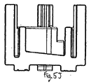
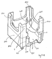
図49A−59Cに見られるような本発明の一実施例では、「厚いシェル/薄い内側」構成が提供される。4つのブロックの設計図は図面49に示される。これらのブロックは、縦方向の出口ブロック(図49A、図52と図56A−Cに詳細を表示)、単独の出口ブロック(図49B、図53および図57A−57Cに詳細を表示)、向き合う二重出口ブロック(図49C、図54と図58A−58Cに詳細を表示)および、四重の出口ブロック(図49D、図55と図59A−59Cに詳細を表示)を含む。これらの4つの図面のブロック上および内部を移動する球体のパスウェイは、それぞれ、円、楕円、砂時計上、および十字として説明できる。
(D. member example)
In one embodiment of the invention as seen in FIGS. 49A-59C, a “thick shell / thin inner” configuration is provided. A design diagram of the four blocks is shown in FIG. These blocks include a vertical exit block (details shown in FIGS. 49A, 52 and 56A-C), a single exit block (details shown in FIGS. 49B, 53 and 57A-57C), two facing Includes a double outlet block (details shown in FIGS. 49C, 54 and 58A-58C) and a quadruple outlet block (details shown in FIGS. 49D, 55 and 59A-59C). The spherical pathways moving on and within the blocks in these four drawings can be described as circles, ellipses, hourglasses, and crosses, respectively.

図50と51は、単独側出口ブロックの構成要素の同じ要素の上下からの等角図である。図50A−2と図51A−2は、例えば、球体の同じ部分と別の角度から示す。図50A−1、50B−1、50C−1、50D−1、51A−1、51B−1、51C−1および51D−1は、ブロックの4つの要素、それぞれ、ブロックを感性させる部分を示す。   50 and 51 are isometric views from above and below of the same components of the single side outlet block. FIGS. 50A-2 and 51A-2 show, for example, from the same part of the sphere and another angle. 50A-1, 50B-1, 50C-1, 50D-1, 51A-1, 51B-1, 51C-1, and 51D-1 show the four elements of the block, respectively, the parts that make the block sensitive.

図50A−1および51A−1は、1/16インチの厚さの半球体600を示す。図A−2は、この半球体からの四角形の切断片を示す。この半球形状は、最終の立方体の中心になる。図49に示される4つのブロックすべては、部分的に、この半球体から構成される。この半球体600の現在の部分は、回転する球体(例えばビー球)を受け取り、この球体は、球体形状のこれらの部分の上に着地して、重力により、球体の低い点へと導かれて、各ブロックの中間に導かれる。   50A-1 and 51A-1 show a hemisphere 600 that is 1/16 inch thick. FIG. A-2 shows a square cut piece from this hemisphere. This hemispherical shape is the center of the final cube. All four blocks shown in FIG. 49 are partially composed of this hemisphere. The current part of the hemisphere 600 receives a rotating sphere (eg, a bee sphere) that lands on these parts of the sphere shape and is directed by gravity to a low point on the sphere. , Guided in the middle of each block.

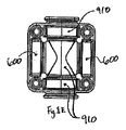
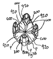
図50B−1、51B−1および53B−1は、単独の側面出口のための球体/ビー球出口パスウェイ900を示す。図54B−1は、向き合う二重の出口パスウェイ910を示し、図55B−1は、四重の出口パスウェイ920を示す。図50B−2と51B−2は、球体600により切断された後の図50B−1と51B−1からのパスウェイ900を示す。図50E−1および51E−1は、それぞれ、図50A−2と50B−2、図51A−2と図51B−2を合わせた図を示し、球体600とパスウェイ900が組み合わされる。すると、少なくとも1つの出口パスウェイを備える上向きの凸面の床が形成される。2つの出口、3つの出口、および4つの出口のある部材の場合には、上向きの凸面の床は、それぞれ、そこに形成される2つ、3つ、および4つの出口パスウェイを有する。   50B-1, 51B-1 and 53B-1 illustrate a sphere / bee ball exit pathway 900 for a single side exit. FIG. 54B-1 shows a double exit pathway 910 facing each other, and FIG. 55B-1 shows a quadruple exit pathway 920. 50B-2 and 51B-2 show pathway 900 from FIGS. 50B-1 and 51B-1 after being cut by sphere 600. FIG. FIGS. 50E-1 and 51E-1 show a combination of FIGS. 50A-2 and 50B-2, FIGS. 51A-2 and 51B-2, and a sphere 600 and a pathway 900 are combined. This forms an upwardly convex floor with at least one exit pathway. In the case of a member with two outlets, three outlets, and four outlets, the upwardly convex floor has two, three, and four outlet pathways formed therein, respectively.

図50C−1は、ブロックの内部山留壁700を示す。これらは、4つの縦方向の交差壁である。これらの壁は、型の2つの部分の関係に応じて、内向きまたは外向きの抜き勾配を有することができる。図50C−2は、球体600により切断された後の山留壁を示す。図50E−2は、図50E−1および51C−2をあわせた図、または、球体、パスウェイ、山留壁をあわせた図を示す。縦方向の出口ブロック、二重の出口ブロックおよび四重の出口ブロックの場合、パスウェイの形状の違いは、これらの3つの部分を合わせた結果を変化させる。山留壁は、ブロックの向き合う面を接続するので、曲げ力は、ブロックのある部分から別の部分へ移り、全体的な強度を増すように「協調して機能」するさまざまな部分が得られる。山留壁の球体切断により、ブロックに球体/ビー球の流れを妨げることなく、最大の力に備えて、外壁をできるだけ高くすることができる。球体を接合の上に配置することにより、融解プラスチックが接合部分を流れることを助ける。図2Bに示される代わりの実施例では、球体の上の追加の控え壁720が、外側の縦方向のサポート壁に強度を提供する。また、控え壁720は、オスのU字接合の縦方向の構成要素のふちの回転に耐える。   FIG. 50C-1 shows an internal mountain retaining wall 700 of the block. These are four longitudinal intersecting walls. These walls can have an inward or outward draft depending on the relationship between the two parts of the mold. 50C-2 shows the mountain retaining wall after being cut by the sphere 600. FIG. FIG. 50E-2 is a diagram in which FIGS. 50E-1 and 51C-2 are combined, or a diagram in which a sphere, a pathway, and a mountain wall are combined. In the case of a longitudinal exit block, a double exit block and a quadruple exit block, the difference in the shape of the pathway will change the combined result of these three parts. The Yamato wall connects the opposing faces of the block, so the bending force moves from one part of the block to another, giving you various parts that "work in concert" to increase the overall strength . The sphere cutting of the retaining wall allows the outer wall to be as high as possible in preparation for maximum force without interfering with the flow of the sphere / Bee sphere in the block. Placing the sphere over the joint helps the molten plastic flow through the joint. In an alternative embodiment shown in FIG. 2B, an additional retaining wall 720 on the sphere provides strength to the outer longitudinal support wall. The retaining wall 720 also withstands the rotation of the edge of the vertical component of the male U-junction.

図50D−1と51D−1は、1/8インチの厚さの面800と、0.1インチの直径の丸い頂点のある立方体を表示する。図50D−2と51D−2は、この同じ立方体を、上に四角い穴、側面に4つの側面入口、側面に単独の出口、および、ビー球のパスウェイの下側にアクセスする底の型半分のために底に切断された穴とともに示す。側面壁800の側面入口を切断すると、4つの縦方向の「L字形」隅ができる。これらの隅は、構成要素840として示される。部分840は、ブロックが連結できる「メス」接合の側面を備える。   50D-1 and 51D-1 display a cube with a 1/8 inch thick face 800 and a rounded apex 0.1 inch in diameter. 50D-2 and 51D-2 show this same cube with a square hole on the top, four side inlets on the side, a single outlet on the side, and a bottom mold half that accesses the bottom side of the marble path. It is shown with a hole cut in the bottom. Cutting the side entrance of the side wall 800 creates four longitudinal “L-shaped” corners. These corners are shown as components 840. Portion 840 includes “female” joint sides to which the blocks can be coupled.

図50E−3と51E−3は、図50E−2の薄い内部部分と、図50D−2の厚い外側シェルを合わせて示す。つまり、図E−3のブロックは、それぞれ、図50A−1、図50B−1、図50C−1および図50D−1に見られるように、「薄い」1/16インチの半球部分と、パスウェイ、山留、および「厚い」1/インチの立方体の組み合わせである。   50E-3 and 51E-3 show the thin inner portion of FIG. 50E-2 and the thick outer shell of FIG. 50D-2 together. That is, the blocks of FIG. E-3 are divided into “thin” 1/16 inch hemispheres and pathways, as seen in FIGS. 50A-1, 50B-1, 50C-1 and 50D-1, respectively. , Yamadome, and “thick” 1 / inch cubes.

図53B−1と図53C−1は、追加のオス接合200を備える単独の出口ブロックを示す。ブロックすべてのオス接合は単独、二重、四重出口ブロックのパスウェイ構造900、910および920と隙間なく合う。分割線Pは、前の実施例のように、立方体ブロックのおよそ中心周辺を水平方向に進み、オス接合の先で下向きになり、各出口の低い点を進む。   53B-1 and 53C-1 show a single outlet block with an additional male junction 200. FIG. The male joints of all of the blocks fit with single, double and quad exit block pathway structures 900, 910 and 920 without gaps. The dividing line P, as in the previous embodiment, runs horizontally around the center of the cube block, goes down at the tip of the male joint, and goes down the low point at each exit.

図53B−2は、単独の側面出口ブロックの底の図を示す。このブロックの同じ図は、図1063で詳細拡大図を見ることができる。ブロックの1/8インチの厚さの底は、番号810により示される。出口の下では、(50D−2に示されるように)ブロックの底が切り分けられている。表面810は、このような場所から切り分けられており、表面900の図と、表面600の2つの非常に細かい部品が明らかになる。出口の下の立方体の1/8インチの厚さの残りの壁は、820として示される。山留700も、出口の下の表面810の切り分けにより明らかになる。   FIG. 53B-2 shows a bottom view of a single side exit block. The same view of this block can be seen in FIG. The 1/8 inch thick bottom of the block is indicated by the number 810. Below the outlet, the bottom of the block is carved (as shown in 50D-2). Surface 810 has been carved from such a location, revealing a view of surface 900 and two very fine parts of surface 600. The remaining 1/8 inch thick wall of the cube below the outlet is shown as 820. Yamadome 700 is also revealed by carving surface 810 below the exit.

図54C−3は、二重出口のある向かい合うブロックからの切断図で、パスウェイ表面910は、オス接合200とぴったり合わさっていることを見ることができる。800の内面と表面910との交差は、オス接合200の上面とおよそ水平方向に配置される。接合200の圧力と曲げは、この配列により、残りのブロックの深くに伝えられる。設計全体の湾曲は、使用中の圧力を最小限に抑える。また、これらの湾曲は、射出成形に伴う可能性がある圧力も最小限に抑える。鋭角90度の隅の一部は、冷却中に反る傾向があるが、この傾向はこれらの湾曲の使用により削減される。   54C-3 is a cut away view from an opposing block with a double exit, and it can be seen that the pathway surface 910 is mating with the male joint 200. FIG. The intersection of the inner surface of 800 and the surface 910 is disposed approximately horizontally with the upper surface of the male joint 200. The pressure and bending of the bond 200 is transmitted deep in the remaining blocks by this arrangement. The overall design curvature minimizes pressure during use. These curves also minimize the pressure that can be associated with injection molding. Some of the acute 90 degree corners tend to warp during cooling, but this tendency is reduced by the use of these curves.

図1067の切断線に見られるパスウェイ910の湾曲は、出口壁820と湾曲700と一緒になって、その部分の曲げに抵抗するはりを作成する。同様な配置は四重出口ブロックでも明らかである。   The curvature of pathway 910 seen at the cutting line in FIG. 1067, together with exit wall 820 and curve 700, creates a beam that resists bending of that portion. A similar arrangement is evident with the quad exit block.

縦方向のオス接合410は、ブロックの縦方向の交差を可能にする。   The vertical male joint 410 allows for the vertical crossing of the blocks.

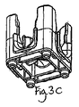
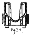
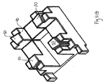
本発明の別の実施例では、図1A−1L、2A−2L、3A−3L、4A−4L、60A−60C、61A−61C、62A−62Cおよび63A−63Cに見られるように、別の「厚いシェル/薄い内部」構造が提供される。これらの図面に見られるように、この実施例は、前の「薄いシェル/薄い内部」実施例と多数の類似点を共有する。しかしながら、図60A−60C、61A−61C、62A−62Cおよび63A−63Cに示される実施例は、その他の機能の中でも、各水平方向出口のU接合を含む。この実施例の縦方向出口ブロック図は、図60A−60Cに見られ、図56A−56Cに見られる実施例の縦方向出口ブロック図に対応する。この実施例の単独出口ブロック図は図61A−61Cに見られ、図57A−57Cに見られる実施例の単独出口ブロック図に対応する。この実施例の向かい合う二重出口ブロック図は、図62A−62Cに見られ、図58A−58Cに見られる実施例の向かい合う二重出口ブロック図に対応する。また、この実施例の四重出口ブロック図は、図63A−63Bに見られ、図59A−59Cに見られる実施例の四重出口ブロック図に対応する。   In another embodiment of the invention, as seen in FIGS. 1A-1L, 2A-2L, 3A-3L, 4A-4L, 60A-60C, 61A-61C, 62A-62C and 63A-63C, A “thick shell / thin internal” structure is provided. As seen in these drawings, this embodiment shares many similarities with the previous “thin shell / thin interior” embodiment. However, the embodiments shown in FIGS. 60A-60C, 61A-61C, 62A-62C and 63A-63C include a U-junction for each horizontal outlet, among other functions. The longitudinal exit block diagram for this embodiment is seen in FIGS. 60A-60C and corresponds to the longitudinal exit block diagram for the embodiment seen in FIGS. 56A-56C. The single exit block diagram for this embodiment is seen in FIGS. 61A-61C and corresponds to the single exit block diagram for the embodiment found in FIGS. 57A-57C. The opposing double exit block diagram of this embodiment is seen in FIGS. 62A-62C and corresponds to the opposing dual exit block diagram of the embodiment seen in FIGS. 58A-58C. Also, the quad exit block diagram of this embodiment is seen in FIGS. 63A-63B and corresponds to the quad exit block diagram of the embodiment seen in FIGS. 59A-59C.

控え壁720は、図1B、2B、3Bおよび4Bに見られるように、ブロックの隅を強化してサポートする。各控え壁720の上面のカーブは、製造中の型の超高温気体による燃焼の可能性を減少させて、部材を扱う場合にユーザーに安心感が提供され、連結される部材のオスの縦接合を所定の位置に入れる。   The buttress wall 720 strengthens and supports the corners of the block, as seen in FIGS. 1B, 2B, 3B and 4B. The curve on the top surface of each buttress 720 reduces the possibility of burning with the ultra-hot gas of the mold being manufactured, providing a sense of security to the user when handling the members, and the male vertical joint of the members to be joined In place.

縦方向の管410は、4つの隅のそれぞれに通り、配線、針金、紐などが複数のブロックを通過して、包装または製品の使用を助けることができる(例えば、天井から吊り下げられるモービルの作成)。   The longitudinal tube 410 passes through each of the four corners and allows wires, wires, strings, etc. to pass through multiple blocks to aid in the use of the packaging or product (e.g., mobiles suspended from the ceiling). Create).

突き出しピンは、内壁1000の交差とならぶので、突き出し力は、その部分の形状に渡って均等に分散される。出口パスウェイも、立方体全体の端を越えて、一端が飛び出す。   Since the protruding pin is aligned with the intersection of the inner walls 1000, the protruding force is evenly distributed over the shape of the portion. The exit pathway also protrudes beyond the end of the entire cube.

(II.ビー球の流れ)
複数の同様なモジュール式部材が、組み立てられて、およそ配列されると、接合システムを使用してもしなくても、パスウェイは、ある部材の出口が別の部材の入口と並ぶ場合には必ず定義される。この配列により、ユーザーが戦略的あるいは無計画のやり方で構築しているかどうかに応じて、予定のまたは予定外のパスウェイ構成が作成される。各ブロックからは1つの出口があるので、決して出口がない状態にはならない。無計画または直感的な作成過程により、パスウェイは、注意深く計画した構造のように機能することができる。基本的なパスウェイの構成例は、図18B、19B、20B、21Bおよび22Bに示される。
(II. Flow of bee balls)
When multiple similar modular members are assembled and roughly aligned, a pathway is defined whenever an outlet of one member is aligned with an inlet of another member, with or without a joining system Is done. This arrangement creates scheduled or unplanned pathway configurations depending on whether the user is building in a strategic or unplanned manner. Since there is one exit from each block, there will never be no exit. With an unplanned or intuitive creation process, the pathway can function like a carefully planned structure. Examples of basic pathway configurations are shown in FIGS. 18B, 19B, 20B, 21B and 22B.

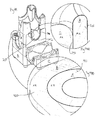
床や壁の形状など、各モジュール式部材の外形や寸法ならびに各部材の内室は、非常にさまざまにできるので、組み立てられた部材により作成されるパスウェイシステムを移動する球体またはその他の物体の振る舞いは、かなり異なることがある。望まれる効果に応じて、部材の内室の適切な形状と寸法を選択することができる。   The shape and dimensions of each modular member, such as the shape of the floor and walls, as well as the interior of each member can vary widely, so the behavior of a sphere or other object moving through the pathway system created by the assembled member is Can be quite different. Depending on the desired effect, the appropriate shape and dimensions of the inner chamber of the member can be selected.

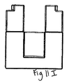
図13A−13Jに見られる一実施例において、部材の内室は、円筒状の壁(図13Dに表示)および部材の水平方向出口に向かう下向きの傾斜した床(図13J)を含む。図18Bを参照すると、図13A−13Jに見られる立方体状部材の基本的な縦列構成が示されているが、一番上の部材Aに置かれたまたは落とされたビー球のような球体は、床領域の傾斜により、部材の唯一の水平方向出口に向かう部材の床領域に沿って、回転を始める。この例では、部材は、分割接合により接合され、ビー球は、部材Aから出る場合、部材Aのオス接合の2つの側面を通過する。その後、ビー球は、部材Bの水平方向入口に入り、入口から、部材Bの床領域に落下する。この落下は、各部材の水平方向入口は、その床領域よりも高いために、確保される。次に、ビー球の速度に対する水平方向構成要素と部材Bの床領域の傾斜の組み合わせにより、ビー球は、水平方向出口に向かって、部材Bの床領域に沿って回転を続ける。この過程は、ビー球が最も低い部材の部材Dに達して外に出るまで続く。   In one example seen in FIGS. 13A-13J, the interior chamber of the member includes a cylindrical wall (shown in FIG. 13D) and a downwardly inclined floor (FIG. 13J) toward the horizontal outlet of the member. Referring to FIG. 18B, the basic tandem configuration of the cubic member seen in FIGS. 13A-13J is shown, but a sphere like a bead placed or dropped on the top member A is The tilt of the floor area begins to rotate along the floor area of the member towards the only horizontal outlet of the member. In this example, the members are joined by split joining, and the bee sphere passes through the two sides of the male joint of member A as it exits member A. Thereafter, the bee ball enters the horizontal entrance of member B and falls from the entrance to the floor area of member B. This fall is ensured because the horizontal entrance of each member is higher than its floor area. Next, due to the combination of the horizontal component and the slope of the floor area of member B with respect to the speed of the marble, the marble continues to rotate along the floor area of member B toward the horizontal outlet. This process continues until the bead reaches the lowest member D and exits.

図13A−13Jに見られる立方体状の部材を使用する図19Aの縦列構成では、ビー球は、部材から部材に移動するにつれて、速度が速くなる。このように、構成を移動しているビー球は、ある部材に沿って回転するにつれて、回転−落下−回転経路をたどり、隣の部材に落下して、再び、次の部材に向かって回転を始める。この回転−落下−回転経路には、ビー玉が最も上にある部材から最も下にある部材に移動する速度を制御するという利点がある。具体的に言うと、ビー球の速度は、別の部材への各縦方向落下により遅くなる。従って、縦方向の落下が大きくなればなるほど、この落下が床の跳ね返りが大きくなり、回転している球体が外に出る前に、室内で跳ね返る程度にまで、速度を遅くする効果が大きくなる。このように、図65Mに見られるように、モジュール式部材が細長い縦方向の寸法を有する場合、本発明の実施例は、図65Nに見られるように、モジュール式部材が切断された縦方向の寸法を有する場合に比べて、ビー球の速度をもっと制御する。   In the tandem configuration of FIG. 19A using the cube-shaped member seen in FIGS. 13A-13J, the bee sphere increases in speed as it moves from member to member. In this way, as the ball moving in the configuration rotates along a certain member, it follows the rotation-drop-rotation path, falls on the next member, and rotates toward the next member again. start. This rotation-drop-rotation path has the advantage of controlling the speed at which the marble moves from the uppermost member to the lowermost member. More specifically, the speed of the marble is slowed by each longitudinal drop on another member. Therefore, the greater the drop in the vertical direction, the greater the bounce of the floor, and the greater the effect of slowing the speed to the extent that the rotating sphere will bounce off the outside before going out. Thus, as seen in FIG. 65M, if the modular member has an elongate longitudinal dimension, embodiments of the present invention can be seen in FIG. More control over the speed of the marbles compared to having dimensions.

ビー球の速度を制御する本発明の別の側面は、パスウェイの構成である。例えば、図13A−13Jに見られる立方体状の部材を使用しているスラローム構成(例えば図19B)、またはジグザグ構成(例えば図22B)では、隣の部材の水平方向入口に入るビー球は、隣の部材の床領域に落下して、ビー球が入ってきた入口の向かい側の内壁を打つ(「打撃壁」)。そして、ビー球は、床に沿って回転し、打撃壁の隣(スラローム)または打撃壁の向かい側(ジグザグ)のいずれかである、部材の水平方向出口に向かう。打撃壁にあたるとビー球にかかる衝撃が減少し、ビー球の速度を変更するので、ビー球の速度が制御される。当業者は、異なるパスウェイ構成が異なる速度制御を達成することを理解する。例えば、図18Bに示されている縦列構成では、ビー球は打撃壁に合うことがないので、速度制御が最小限になり、ビー球の速度が最高になる(縦方向出口部材を含まない)。縦列構成の唯一の速度制御は、回転−落下−回転と上記の跳ね返り側面により提供される。対照的に、スラローム、らせん、およびジグザグ構成などその他の構成では、ブロックの内側の壁との衝撃中に、水平方向の速度が繰り返し失われることにより、縦列構成と比較すると、かなりの速度制御が提供される。   Another aspect of the present invention for controlling the speed of the bee sphere is the pathway configuration. For example, in a slalom configuration (eg, FIG. 19B) or a zigzag configuration (eg, FIG. 22B) using a cubic member as seen in FIGS. 13A-13J, The member falls to the floor area of the member and hits the inner wall opposite to the entrance where the bee ball enters (“blow wall”). The bee sphere then rotates along the floor and heads towards the horizontal exit of the member, either next to the striking wall (slalom) or opposite the striking wall (zigzag). When hitting the striking wall, the impact on the marble is reduced and the velocity of the marble is changed, so that the velocity of the marble is controlled. One skilled in the art understands that different pathway configurations achieve different speed controls. For example, in the tandem configuration shown in FIG. 18B, the bee ball does not fit the striking wall, thus minimizing speed control and maximizing the speed of the bee ball (not including the longitudinal exit member). . The only speed control of the tandem configuration is provided by the rotation-drop-rotation and the bounce side described above. In contrast, other configurations, such as slalom, helix, and zigzag configurations, provide significant speed control compared to tandem configurations due to repeated loss of horizontal speed during impact with the inner wall of the block. Provided.

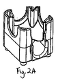
上記の「厚いシェル/薄い内部」実施例では、部材の床は、実質的に上向きの凸面であり、床には少なくとも1つの出口パスウェイが形成されている。上向きの凸面の床は、これらの部材を移動する球体に振動作用を作り出すので、パスウェイを通過するビー球の流れを遅くするまた別の装置として働く。例えば、内室に入るビー球は、床に落下すると、このとき、上向き凸面の床はビー球を床中央に向かわせる。図1A−1Lに見られるような向かい合う2つの出口のある部材では、ビー球は、典型的に、床の中央に向かい、上向きに凸面の床の形状により、ビー球が最終的に上向き凸面の床に形成されている出口パスウェイに落下するまで、ビー球には振動運動が生成され、ビー球は2つの出口の1つに向かって移動する。   In the “thick shell / thin interior” embodiment described above, the floor of the member is a substantially upward convex surface with at least one exit pathway formed in the floor. The upwardly convex floor acts as another device that slows the flow of the marbles through the pathway, as it creates a vibrating action on the sphere moving these members. For example, when a bee ball entering the inner chamber falls to the floor, the upward convex floor causes the bee ball to face the center of the floor. In a member with two exits facing each other as seen in FIGS. 1A-1L, the bee sphere is typically directed toward the center of the floor, and the upward convex convex floor shape results in the bee sphere being eventually upwardly convex. Until it falls on the exit pathway formed in the floor, a vibrating motion is generated in the bee sphere, which moves towards one of the two exits.

図2A−2Kに見られる1出口部材の出口パスウェイは、特にビー球が出口チャネルに対して垂直な1出口部材に入ると、球体に振動作用を促進する、上向きに凸面の球体の中央近くで始まる。出口パスウェイの開始点は、望む場所に設けることができる。例えば、図532−Aに示される部材の出口パスウェイは、図2Dに示される部材の出口パスウェイに比較すると、さらに後ろにある。   The exit pathway of the 1 exit member seen in FIGS. 2A-2K is near the center of the upwardly convex sphere, which facilitates the oscillating action on the sphere, especially when the bee ball enters the 1 exit member perpendicular to the exit channel. Begins. The starting point of the exit pathway can be provided where desired. For example, the exit pathway of the member shown in FIG. 532-A is further back compared to the exit pathway of the member shown in FIG. 2D.

図1Dに示される2出口ブロックの砂時計の形状は、円環面と上向き凸面球体の近似交差としてよく理解できる。円環面に対して球体はわずかに高い位置にあるので、砂時計としての設計で、砂時計形状を「見る」ことができる。その他の形状の無限の多様性により、2つの出口の1つにビー球を無作為に誘導する同様な機能を作成することが可能である。砂時計の形状は、特別な作用を提供する。例えば、回転するビー球が、振動運動で十分速度が遅くなると、非常に平衡が不安定な場合には、球体の底ではなく、円環面の上部になる。球体上と砂時計の上を前後に回転しているビー球は、砂時計構造の頂上部にあたると、かすかな衝撃音を出す。円環面と球体は、反対方向に曲がるので、この二重湾曲は、ブロックに強度を追加する。   The shape of the hourglass of the two exit block shown in FIG. 1D can be well understood as an approximate intersection of an annular surface and an upward convex sphere. Since the sphere is slightly higher than the torus, the hourglass shape can be “seen” with the hourglass design. With the infinite variety of other shapes, it is possible to create a similar function that randomly guides a bead to one of the two exits. The shape of the hourglass provides a special action. For example, when the rotating bee sphere is sufficiently slow due to the oscillating motion, if the equilibrium is very unstable, it is not the bottom of the sphere but the top of the torus. The bee sphere rotating back and forth on the sphere and the hourglass makes a faint impact sound when it hits the top of the hourglass structure. Since the torus and sphere bend in opposite directions, this double curve adds strength to the block.

(A.配列原理)
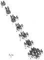
上記のように、複数の同様な部材(例えば、立方体、三角形、四角形、球体、十字形など)は、図18B、19B、20B、21Bおよび22Bに見られるような様々な構成に組み立てることができる。これらの基本的または「基礎的」構成に加えて、もっと革新的で図形的に複雑な配列も組み立てることができる。部材の属性と入口/出口構成に関して上記の基礎原理は、これらの配列も支配する。
(A. Arrangement principle)
As described above, a plurality of similar members (eg, cubes, triangles, squares, spheres, crosses, etc.) can be assembled in a variety of configurations as seen in FIGS. 18B, 19B, 20B, 21B and 22B. . In addition to these basic or “basic” configurations, more innovative and graphically complex arrays can also be assembled. The basic principles described above with respect to member attributes and inlet / outlet configuration also govern these arrangements.

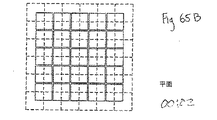
例えば、1/2Aの高さの縦方向のオフセットまたはずれが、任意の2つの隣り合う部材間に存在する。これにより、「偏移直交空間」の3次元格子を表す、高低高の効果が達成される。一体構造に構成された一連の立方体状部材を上から見た図64Aに見られるように、各「高い」部材(つまり高くなっている)は、「低い」部材に直接囲まれており、「高い」部材と「低い」部材の間の高さの違いは、部材の縦方向の高さの半分である。この結果は、図64Aに見られるように、市松模様に似ている。   For example, a longitudinal offset or shift of 1/2 A height exists between any two adjacent members. This achieves a high and low effect representing a three-dimensional lattice of “shifted orthogonal space”. As seen in FIG. 64A, which is a top view of a series of cubic members configured in a unitary structure, each “high” member (ie, higher) is directly surrounded by “low” members, The height difference between the “high” and “low” members is half the longitudinal height of the member. This result resembles a checkered pattern as seen in FIG. 64A.

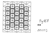
「偏移直交空間」は、図65A−65Cに示される直交空間に配置された立方体を、図65D−65Fに示される「変異直交空間」に配置された立方体と比較すると、理解できる。後者の立方体は、立方体の高さの半分だけ、縦方向にずれる。図65G−65Iに示された立方体は、立方体の高さの三分の二だけ縦方向にずらして配置される。図65J−65Lに示される部材は立方体ではなく、細長いが、立方体の高の1/2だけ縦方向にずれる。図65Mと65Nに見られるように、このように細長い部材を縦方向または水平方向に構成しても縦方向のオフセットはなくならない。   The “shifted orthogonal space” can be understood by comparing the cube arranged in the orthogonal space shown in FIGS. 65A-65C with the cube arranged in the “mutant orthogonal space” shown in FIGS. 65D-65F. The latter cube is shifted in the vertical direction by half the cube height. The cubes shown in FIGS. 65G-65I are arranged vertically shifted by two-thirds of the cube height. The members shown in FIGS. 65J-65L are elongate, not cubes, but deviate longitudinally by half the cube height. As seen in FIGS. 65M and 65N, even if the elongated member is configured in the vertical direction or the horizontal direction, the vertical offset does not disappear.

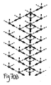
同様な効果は、三角形部材(図68および64B)、六角形部材(64Cおよび64D)、八角形部材(図64E)および円部材(図64Fおよび64G)にも見ることができる。立方体の実施例(64A)、三角形の実施例(図64B)および六角形の実施例(64C)の1つは、空間のない「一体」構造を提供する。対照的に、別の六角形の実施例(図64D)、八角形の実施例(図64E)および円の実施例(図64Fおよび64G)は、それぞれの図面に見られるように、構造内に空間がある。さらに、図64Dに見られるように、六角形の実施例の1つは、6つの三角形を備える六角形に沿って、基底に三角形を含むことができる。さらに、八角形の実施例(図64E)および円の実施例の1つ(図64F)は、基底格子図形を含むことができ、別の円の実施例(図64G)は、基底の三角形図を含むことができる。   Similar effects can be seen for triangular members (FIGS. 68 and 64B), hexagonal members (64C and 64D), octagonal members (FIG. 64E) and circular members (FIGS. 64F and 64G). One of the cubic embodiment (64A), the triangular embodiment (FIG. 64B) and the hexagonal embodiment (64C) provides a “monolithic” structure with no space. In contrast, another hexagonal embodiment (FIG. 64D), an octagonal embodiment (FIG. 64E) and a circular embodiment (FIGS. 64F and 64G) can be found in the structure as seen in the respective drawings. There is space. Further, as seen in FIG. 64D, one of the hexagonal embodiments can include a triangle in the base along a hexagon with six triangles. In addition, the octagonal embodiment (FIG. 64E) and one of the circle embodiments (FIG. 64F) can include a base grid pattern, and another circle embodiment (FIG. 64G) can be used to create a base triangle diagram. Can be included.

特定の実施例のモジュール式部材が、図64Aに見られる円の実施例、図64Eに見られる八角形の実施例および図64Fに見られる円の実施例のように、基底の格子図を含む場合、部材の図形中心も、実質的に、格子上に配置される。例えば、一連の立方体部材は、配列の一番上から見た図66Aのように構成できるが、各部材の図形中心は、点により表されている。部材の図形中心は、図66Aに見られるように、列(0,1,2、…)と行(I,II,III…)により配置される。さらに、一連の立方体部材は図66Bに見られるように構成できるが、これは、配列の切断図である。ここでは、部材の図形中心は、交代列(例えば、列1、5、9の部材は縦方向に並び、列3、7、11の部材は縦方向に並ぶ)の部材の図形中心と縦方向に並ぶ。また、部材の図形中心は、中間で、隣の列(例えば、列1の部材は、中間で列3の部材と縦方向に並び、列3の部材は、中間で列5の部材と縦方向に並ぶ)の部材の図形中心に並ぶ。図66Bの同じ列の部材の図形中心はすべて水平方向に並ぶ。   Certain example modular members include a base grid diagram, such as the circle embodiment seen in FIG. 64A, the octagonal embodiment seen in FIG. 64E, and the circle embodiment seen in FIG. 64F. In this case, the figure center of the member is also substantially arranged on the grid. For example, a series of cubic members can be configured as shown in FIG. 66A viewed from the top of the array, but the graphic center of each member is represented by a point. The figure centers of the members are arranged by columns (0, 1, 2,...) And rows (I, II, III...) As seen in FIG. 66A. Further, a series of cubic members can be configured as seen in FIG. 66B, which is a cutaway view of the array. Here, the figure center of the member is the figure center of the member in the alternating row (for example, the members in rows 1, 5, 9 are arranged in the vertical direction, and the members in rows 3, 7, 11 are arranged in the vertical direction) Lined up. In addition, the graphic center of the member is in the middle and the adjacent row (for example, the member in row 1 is arranged in the vertical direction with the member in row 3 in the middle, and the member in row 3 is in the vertical direction with the member in row 5 in the middle Lined up at the center of the figure of the member. The graphic centers of the members in the same row in FIG. 66B are all arranged in the horizontal direction.

明らかなように、図66Aと66Bに示される図形中心の配列は、立方体部材を参照して説明する。しかしながら、説明される図形中心の格子配列は、八角形、円および十字形の実施例など、その他の形状にも適用することができる。同様に、上記の基底の三角形は、六角形や円の実施例などその他の実施例にも適用できる三角形の配列をもたらす。従って、異なる形状や構造の部材は、特定の彫刻構造に関係なく、同じやり方で配列することができる。   As will be apparent, the graphic center arrangement shown in FIGS. 66A and 66B will be described with reference to cube members. However, the figure-centric grid arrangement described can also be applied to other shapes, such as octagonal, circular and cross-shaped embodiments. Similarly, the base triangles described above provide an array of triangles that can be applied to other embodiments, such as hexagonal and circular embodiments. Thus, members of different shapes and structures can be arranged in the same way regardless of the particular engraving structure.

再び65Aを参照すると、空間のない従来の直交空間に配列された内部立方体のそれぞれは、6面が隣と接する(このような一体構成の外側の立方体は、3、4または5つの面で隣接する)対照的に、65Dを参照すると、空間のない偏移直交空間構成に配置された内部の立方体は、2面(上下)が隣に接しており、側面周囲では、8つの半面が隣に接する。   Referring again to 65A, each of the inner cubes arranged in a conventional orthogonal space with no space is adjacent to six sides (an outer cube in such a unitary configuration is adjacent on three, four or five sides). In contrast, referring to 65D, an internal cube arranged in a space-free shifted orthogonal space configuration has two sides (top and bottom) next to each other, and around the side, eight halves are next to each other. Touch.

(B.基本構成)
このように、同様な部材の基本構成には、タワー(図40B)、縦列(図18B)、スラローム(図19B)、らせん(図20B)、二重らせん(図21B)およびジグザグ(図22B)などがある。また、このように、参照された図面のそれぞれは、立方体部材によるこれらそれぞれのパスウェイ構成を表すが、構成は、その他さまざまな形状の部材によっても実現される。例えば、図23Bは、十字形部材により形成されたスラローム構成を示す。
(B. Basic configuration)
Thus, the basic components of similar members include tower (Fig. 40B), column (Fig. 18B), slalom (Fig. 19B), helix (Fig. 20B), double helix (Fig. 21B) and zigzag (Fig. 22B). and so on. Thus, although each of the referenced drawings represents a respective pathway configuration with a cubic member, the configuration may be implemented with other various shaped members. For example, FIG. 23B shows a slalom configuration formed by a cross-shaped member.

(C.無制限の構造例)
さまざまな配列タイプは、複数の同様な部材から組み立てることができる。これらの異なる配列は、一般的に、一体構造、シェル構造、格子構造および平面/交差平面構造という4つのタイプに分けることができる。
(C. Unlimited structure examples)
Various arrangement types can be assembled from a plurality of similar components. These different arrangements can generally be divided into four types: monolithic structures, shell structures, lattice structures and planar / cross-planar structures.

例として、一体構造は、ブロック、三角錐、または逆三角錐の形状の組立を含むことができる。この構造タイプは、構造の内側に空間を作らない部材の組立により特徴づけられる。構造能登と側の部材を除く、各部材は、それぞれ可能な位置で隣に接する。図67に見られる構成は、ブロック構成の例で、図47Aと47Bの図に見られる構成は、8面体、三角錐を逆三角錐の上に積み重ねた例である。図48Aと48Bの構成は、外側から見ると、図47Aと47Bの構成に実質的に類似している。違う点は、図48Aと48Bには内側のブロックがないので、「シェル」構造が作られている点である。図68に示される構成は、実質的には三角形であるが、これも一体構造の例である。   As an example, the monolithic structure can include an assembly in the form of a block, a triangular pyramid, or an inverted triangular pyramid. This structural type is characterized by the assembly of members that do not create space inside the structure. Except for the structural Noto and the side members, each member touches the next in a possible position. The configuration shown in FIG. 67 is an example of a block configuration, and the configuration shown in FIGS. 47A and 47B is an example in which an octahedron and a triangular pyramid are stacked on an inverted triangular pyramid. The configuration of FIGS. 48A and 48B is substantially similar to the configuration of FIGS. 47A and 47B when viewed from the outside. The difference is that in FIGS. 48A and 48B there is no inner block, so a “shell” structure is created. The configuration shown in FIG. 68 is substantially a triangle, but this is also an example of a unitary structure.

再び、例として、格子構造は、らせんまたは二重らせん形状の組立を含むことができる。この構造タイプは、オープンな枠組みまたはパターンにより特徴付けられる。前記のように、図20Bに見られる構成は、らせんの例であり、図21Bに見られる構成は二重らせんの例である。図69Aに見られる構成は、大型らせんの例であり、一連の交互の縦列−スラローム−縦列の予備構造を組み合わせることにより形成される。図69Aに見られる構成では、それぞれの「縦列」とそれぞれの「スラローム」の予備構造は、5つのモジュール式部材を含む。しかしながら、当業者は、これらの予備構造が、その他の数の部材を含むことができることを理解する。各予備構造の部材の数が大きくなるほど、らせんの直径は大きくなる。図69Bに示される構成は二重らせんで、それぞれのらせんは、図69Aに示されるらせんと同じである。また、これらのらせんのそれぞれは、一連の交互の縦列−スラローム−縦列の予備構造を組み合わせることにより形成される。図69Cに示される構成は、2つの時計回りと2つの半時計回りのらせんを含み、ノードが交差する場所で二重出口部材で交差する。図69Eは、立方体部材ではなく、球体部材を使用した、図69Cと同じ構成を示す。図69Dに見られる構成は、図69Cの構成を4つ含み、ノードが交差する場所で四重出口部材で一部は重なって交差している。   Again, by way of example, the lattice structure can include a helix or double helix shaped assembly. This structure type is characterized by an open framework or pattern. As described above, the configuration seen in FIG. 20B is an example of a helix, and the configuration seen in FIG. 21B is an example of a double helix. The configuration seen in FIG. 69A is an example of a large helix, formed by combining a series of alternating column-slalom-column preliminary structures. In the configuration seen in FIG. 69A, each “column” and each “slalom” preliminary structure includes five modular members. However, those skilled in the art will appreciate that these preliminary structures may include other numbers of members. The greater the number of members in each preliminary structure, the greater the helix diameter. The configuration shown in FIG. 69B is double helix, and each helix is the same as the helix shown in FIG. 69A. Each of these helices is also formed by combining a series of alternating column-slalom-column preliminary structures. The configuration shown in FIG. 69C includes two clockwise and two counterclockwise helices, intersecting with a double exit member where the nodes intersect. FIG. 69E shows the same configuration as FIG. 69C using a spherical member instead of a cubic member. The configuration seen in FIG. 69D includes the four configurations of FIG. 69C, with the four exit members partially overlapping at the location where the nodes intersect.

平面と交差平面構造は、平面または交差平面形状の組立を含むことができる。図70Aに見られるように、一体平面は、図70Bに見られるように同様な部材から形成することができ、対応する入口/出口構成を備える。図70Dを参照すると、第二の一体平面は、第一の平面と直交することができ、図70Cに見られる対応する入口/出口構造を備える。交差点で、2つの平面構造から交差平面構造を形成するには、4つの出口部材が、2つの出口部材の代わりに使用することができる。あるいは、2つの出口部材は、ある平面から別の平面へと、球体の方向を変えるために、90度回転するようにできる。   Planar and cross-planar structures can include plane or cross-plane shaped assemblies. As seen in FIG. 70A, the unitary plane can be formed from similar members as seen in FIG. 70B, with a corresponding inlet / outlet configuration. Referring to FIG. 70D, the second integral plane can be orthogonal to the first plane and comprises a corresponding inlet / outlet structure as seen in FIG. 70C. To form an intersecting planar structure from two planar structures at the intersection, four outlet members can be used instead of two outlet members. Alternatively, the two outlet members can be rotated 90 degrees to change the orientation of the sphere from one plane to another.

図71Aと71Bを参照すると、平面構造と交差平面構造がそれぞれ示される。実際のモジュール式部材を表示する代わりに、部材は、71A−71Dの立方体により表される。これは、本発明のモジュール式部材により形成可能な配列と構成は、特定の部材の形状にも採用される接合にも依存しないので、適切である。図71Bに示される平面は、図71Cのように平面の中間ではなく、平面の端で交差する。平面の端で交差することにより、図71に示されるように、四角形状が形成できる。図71A−183Dのそれぞれでは、隣の部材は、部材の高さの半分だけ縦方向にオフセットされる。   71A and 71B, a planar structure and an intersecting planar structure are shown, respectively. Instead of displaying the actual modular member, the member is represented by a 71A-71D cube. This is appropriate because the arrangement and configuration that can be formed by the modular member of the present invention does not depend on the shape of the particular member or the bond employed. The plane shown in FIG. 71B intersects at the end of the plane, not in the middle of the plane as in FIG. 71C. By intersecting at the end of the plane, a quadrangular shape can be formed as shown in FIG. In each of FIGS. 71A-183D, adjacent members are offset longitudinally by half the height of the member.

図72A−72Dは、それぞれ、らせん、二重らせん、および四重らせんの立方体により表されるモジュール式部材を示す。ここでも、これらの図から、モジュール式部材の組立から実現される構成に関わらず、縦方向のオフセットが維持されていることがわかる。   72A-72D illustrate modular members represented by a helix, double helix, and quadruple helix cube, respectively. Again, these figures show that the vertical offset is maintained regardless of the configuration realized from the assembly of the modular members.

図73Aを参照すると、立方体により表されるモジュール式部材による、5つの水平方向の平面を備える三角錐構成が示される。ここでも、段差の半分の縦方向のオフセットが維持されていることがわかる。図73B−73Eを参照すると、図73の三角錐の切断面の上平面図は、4つの異なる水平方向の平面に対して示される。特に、図73Bは、一番上の水平方向の平面を示しており、中央上部材A1を含むが、第二の水平方向平面にある4つの追加部材(b1−b4)により囲まれており、A1と一番上の縦方向平面より半分の段差だけ低い。図73Cは、次に下にある水平方向平面を示し、図73Dは、その次の下にある平面、というように示す。   Referring to FIG. 73A, a triangular pyramid configuration with five horizontal planes is shown with modular members represented by cubes. Again, it can be seen that the vertical offset of half the step is maintained. 73B-73E, the top plan view of the triangular pyramid cut surface of FIG. 73 is shown for four different horizontal planes. In particular, FIG. 73B shows the top horizontal plane, including the central upper member A1, but surrounded by four additional members (b1-b4) in the second horizontal plane, A1 is half the level difference from the top vertical plane. FIG. 73C shows the next horizontal plane below, FIG. 73D shows the next lower plane, and so on.

図74A−74Dは、さまざまな構成や配置の三角部材により表される、モジュール式部材を示す。これらの配置は、図15A−15Lのように任意の数の形状で達成され、図15A、15D、15Gおよび15Jの入口/出口構成で説明されるように、これらの中の相互連結パスウェイを持つことができる。図74A−74Dに見られるように、配置は縦方向のオフセットを維持する。   74A-74D show modular members represented by triangular members of various configurations and arrangements. These arrangements can be achieved with any number of shapes, as in FIGS. 15A-15L, with interconnected pathways in them as described in the inlet / outlet configurations of FIGS. 15A, 15D, 15G, and 15J. be able to. As seen in FIGS. 74A-74D, the arrangement maintains a vertical offset.

異なる形状のモジュール式部材は、一致する接合具を持つことができるので、こられの異なる形状部材は接合でき、従って、多角形タイルを組み合わせることができる。図75A−75Dを参照すると、2つの別々の形状(立方体と三角形)のモジュール式部材が表されており、異なる構成にお互いに接合されているのが示される。図75Aは、立方体と三角形部材を交互にして円を作成する構成の上平面図を示し、75Bは、同じ構成の斜視図を示す。図75Aと75Bのそれぞれの行は、図40Bのように、類似形状部材を縦方向に積み重ねることにより、実現可能である。また、図75Cは、立方体と三角形部材を交互にして円を作成する構成の上平面図を示し、75Dは、同じ構成の斜視図を示す。図75Dからは、円を形成している行は、縦方向の非連続性により特徴づけられ、このような部材は、縦方向の接合ではなく、水平方向の接合だけによって支えられていることがわかる。この構成によって、一部の部材は、部材の別の行から、一端が飛び出すことになる。   Since different shaped modular members can have matching fittings, these different shaped members can be joined and thus polygonal tiles can be combined. Referring to FIGS. 75A-75D, two separate shapes (cube and triangle) of modular members are depicted and shown joined together in different configurations. FIG. 75A shows a top plan view of a configuration in which a circle and a triangular member are alternately formed to create a circle, and 75B shows a perspective view of the same configuration. Each row of FIGS. 75A and 75B can be realized by stacking similar shaped members vertically as shown in FIG. 40B. FIG. 75C shows an upper plan view of a configuration in which a circle and a triangular member are alternately formed, and 75D shows a perspective view of the same configuration. From FIG. 75D, the rows forming the circle are characterized by vertical discontinuities, and such members are supported by only horizontal joints, not vertical joints. Recognize. With this configuration, one part of one member protrudes from another line of the member.

従って、「寸法的に類似の」部材とは、実質的に外寸法を共有する部材をいう。(接合具は考慮しない、「寸法的に類似」の部材から、「寸法的に類似の」部材によって変わることができ、さらに、床、壁、その他内室の特徴などの内部形状は考慮しない)。例えば、実質的に同じ高さ、幅、深さの2つの立方体、または、類似の高さと底寸法の2つの三角形など。対照的に、「寸法的に非類似の形状」とは、外部寸法を実質的に共有しない任意の2つの部材を言う。例えば、図75Cと75Dに示される立方体部材と三角形部材は、寸法的に非類似の形状を表し、図5A−5Jに見られる立方体形状部材は、図6A−6Iに示される三角形状とは寸法的に非類似である。   Thus, “dimensionally similar” members refer to members that share substantially the outer dimensions. (Does not consider joints, can vary from “dimensionally similar” members to “dimensionally similar” members, and does not take into account internal shapes such as floors, walls, and other interior features) . For example, two cubes with substantially the same height, width and depth, or two triangles with similar height and bottom dimensions. In contrast, a “dimensionally dissimilar shape” refers to any two members that do not substantially share external dimensions. For example, the cube and triangle members shown in FIGS. 75C and 75D represent dimensional dissimilar shapes, and the cube-like members shown in FIGS. 5A-5J are dimensionally different from the triangles shown in FIGS. 6A-6I. Are dissimilar.

上記構造と構造タイプは、可能な組立の種類を単に説明するものである。配列を作成し構築するその他の手段も使用できる。例えば、配列は、コンピュータ実行アルゴリズムにより生成される構造など、さまざまなアルゴリズムを使用して生成でき、「偏移直交空間」の直交形状(例えば立方体)で作成される構造は、コンピュータアルゴリズムから生成される。あるいは、ユーザーは、一体、格子、平面/交差平面またはこれらの組み合わせである構造を無作為に作成することができる。あるいは、ユーザーは、椅子、ロボット、馬など、その他の物体のようなものを表すようなやり方の表現構造を作成することができる。   The above structures and structure types are merely illustrative of possible types of assembly. Other means of creating and building arrays can also be used. For example, arrays can be generated using a variety of algorithms, such as structures generated by computer-implemented algorithms, and structures created with orthogonal shapes in “shifted orthogonal space” (eg, cubes) are generated from computer algorithms. The Alternatively, the user can randomly create a structure that is monolithic, a grid, a plane / intersection plane, or a combination thereof. Alternatively, the user can create a representation structure in a way that represents something like a chair, robot, horse, or other object.

任意の格子構造は、格子の空間を埋めることによって、一体構造の中に埋め込むことが可能である。このように、固体のブロックは、一連の連結らせん、またはその他のタイプのパスウェイを含むことができる。   Any lattice structure can be embedded in a unitary structure by filling the space of the lattice. Thus, a solid block can include a series of connecting spirals or other types of pathways.

(IV.特別ブロック)
本発明に従い、さまざまな「特別ブロック」が提供できる。これらのブロックは、一般的に、上記の部材と構成および使用することができ、上記の原理のすべてではないが一部に準じることができる。
(IV. Special block)
Various “special blocks” can be provided in accordance with the present invention. These blocks can generally be configured and used with the above members, and may conform to some but not all of the above principles.

このような特別ブロックの1つは、上記の4出口部材に類似した、4出口部材を含む。しかし、このブロックが異なる点は、部材に挿入することができる、取り外し可能なストッパーまたは「ブロックユニット」を提供することにより、任意の出口をブロックすることである。ゼロから3つまでのストッパーを、望む出口をブロックするために、望む場所に挿入できる。これにより、単独の基本的ブロック設計から、複数のブロック出口構成を作成することが可能になる。   One such special block includes a four outlet member similar to the four outlet member described above. However, this block differs in that it blocks any outlet by providing a removable stopper or “block unit” that can be inserted into the member. From zero to three stoppers can be inserted where desired to block the desired exit. This makes it possible to create multiple block exit configurations from a single basic block design.

別の特別ブロックは、図76Aおよび76Bに示される四角傾斜ブロック550である。このブロックは、上記の部材の一部の特徴を共有する。例えば、図76Aと8Bに示される三角傾斜ブロックは、上記の立方体部材と同じ高さ、幅、および接合具を有する。しかし、図76Bの図説から明らかなように、三角傾斜ブロックは、立方体部材よりも、はるかに長い。図76Aと76Bに示される三角傾斜ブロック550の実施例は、1つのユニットの高さと5つのユニットの長さで、8つの水平方向の入口を含む(3つは各側面、1つは各端)。この実施例は、一連の縦方向のオス接合をその下側に3つ含む。図76Aと76Bで明らかなように、部材は、ビー球が回転できる、細長い床を有する。この部材は、図28や29のように、その他の非傾斜部材と使用できる。図28は、4つの単独らせんが、4つの四角傾斜ブロックに接続されていることを示し、図29は、4つのらせんのそれぞれが、追加のサポート部材を含む同様な構成を示す。これらの構成では、らせんに入るビー球には、らせんに残る50%の確率と、四角傾斜ブロックのらせんから出て行く50%の確率がある。   Another special block is the square ramp block 550 shown in FIGS. 76A and 76B. This block shares some features of the above members. For example, the triangular ramp block shown in FIGS. 76A and 8B has the same height, width, and joint as the cube member described above. However, as is apparent from the illustration in FIG. 76B, the triangularly inclined block is much longer than the cubic member. The embodiment of the triangular ramp block 550 shown in FIGS. 76A and 76B includes eight horizontal inlets, three at each side and one at each end, one unit height and five unit lengths. ). This embodiment includes a series of three longitudinal male junctions underneath. As can be seen in FIGS. 76A and 76B, the member has an elongated floor on which the marble can rotate. This member can be used with other non-inclined members as shown in FIGS. FIG. 28 shows that four single helices are connected to four square inclined blocks, and FIG. 29 shows a similar configuration in which each of the four helices includes an additional support member. In these configurations, a bee sphere entering the helix has a 50% probability of remaining in the helix and a 50% probability of leaving the helix of the square sloped block.

管連結は、球体が移動する固いまたは柔軟な管により、相互に接続された互換性のあるメス入口と互換性のあるオス出口を使用して、適切な接合具により、作成される。固い管は、構成の幅広い範囲で使用できるために、はめ込み管にできる。   The tube connection is made by a suitable joint using a male outlet compatible with a compatible female inlet interconnected by a rigid or flexible tube through which the sphere moves. A hard tube can be a telescoping tube because it can be used in a wide range of configurations.

(V.材料、製造および規模)
本発明のモジュール式部材は、さまざまな適当な材料から作成できる。一実施例では、部材は、透明なポリカーボネート、樹脂またはその他のプラスチックから形成される。また、部材は、ガラスまたは金属からも形成できる。あるいは、部材は、4−5インチの立方体で、大型球体で使用可能な、大型形状を形成するために、スポンジから作成することができる。この実施例は、窒息する恐れがあるのでビー球を扱うには幼すぎる子どもにも使用可能なモジュール式部材を提供する。まだ別の実施例では、モジュール式部材は、平坦にすることができるプラスチック(つまり、空気を入れる)を備えることができるので、作成されるパスウェイは、ビーチボールやバレーボールのような大型球体であっても、移動するには十分広くなる。その他の実施例は、木、竹、またはその他彫刻材料から、モジュール式部材を作成することを実現する。あるいは、モジュール式部材は氷から形成される。この実施例では、接合は、操作されて凍結できる雪のような物質にできるので、2つの部材は接着される。従って、図12A−12Jに示される氷の部材の例は、図33A−33B、34A−34D、35A−35C、36A−36、37A−37C、38A−38Cまたは39に見られる接合も、U字接合も一切含まないが、雪のように溶ける接合が、作成時に部材に追加される。さらに、図12A−12Jに示される部材は、球体物体に加えて、液体を運搬するためにも適している。唯一の水平方向の出口は、上記の立方体部材よりもはるかに伸びて、運搬される液体が、適切に、隣の部材の入口を越えて、隣の部材の床に届くことを確保する。その他の同様な部材と構成する場合、図77A−77Cに見られるように、この部材は、望ましいパスウェイ構成に沿って、液体を運搬できる。
(V. Materials, manufacturing and scale)
The modular members of the present invention can be made from a variety of suitable materials. In one embodiment, the member is formed from a clear polycarbonate, resin or other plastic. The member can also be formed from glass or metal. Alternatively, the member is a 4-5 inch cube and can be made from a sponge to form a large shape that can be used with a large sphere. This embodiment provides a modular member that can also be used by children who are too young to handle the ball because of the risk of suffocation. In yet another embodiment, the modular member can comprise a plastic that can be flattened (ie, contains air), so the pathway created is a large sphere such as a beach ball or volleyball. But it is wide enough to move. Other embodiments provide for making modular members from wood, bamboo, or other engraving materials. Alternatively, the modular member is formed from ice. In this embodiment, the joining can be made into a snow-like material that can be manipulated and frozen, so the two members are bonded. Thus, the ice member examples shown in FIGS. 12A-12J are similar to those shown in FIGS. 33A-33B, 34A-34D, 35A-35C, 36A-36, 37A-37C, 38A-38C, or 39. Although it does not include any joints, a joint that melts like snow is added to the member at the time of creation. Furthermore, the members shown in FIGS. 12A-12J are suitable for transporting liquids in addition to spherical objects. The only horizontal outlet extends far beyond the cubic member described above to ensure that the liquid being transported properly passes over the inlet of the adjacent member and reaches the floor of the adjacent member. When configured with other similar members, as seen in FIGS. 77A-77C, this member can carry liquid along the desired pathway configuration.

本発明のモジュール式部材には、さまざまな製造方法も、使用できる。プラスチック、ガラスまたは金属材料から作成されるモジュール式部材では、射出成形、鋳型またはその他の一般的な方法を実装できる。木、竹または同様な材料から作成されるモジュール式部材では、彫刻、ルーティングまたはその他の一般的な方法を実装できる。   Various manufacturing methods can also be used for the modular member of the present invention. For modular members made from plastic, glass or metal materials, injection molding, molds or other common methods can be implemented. With modular members made from wood, bamboo or similar materials, engraving, routing or other common methods can be implemented.

本発明のモジュール式部材は、さまざまな大きさに作成できる。例えば、本発明の立方体部材は、1 1/2インチから2インチの長さを持つことができ、ビー球または金属製ボールベアリングなど1/2から1インチの球体を運搬できる。縮小すると、立方体部材の長さが3/4インチになり、ビー球やベアリングボールなどの1/8インチから1/2インチの球体を運搬して、旅行セットに適している。拡大すると、2インチを超える長さの立方体モジュール式部材となり、テニスボールや遊具ボールまたはビーチボールなど大きい球体の運搬に適している。   The modular member of the present invention can be made in various sizes. For example, the cube member of the present invention can have a length of 11/2 inches to 2 inches and can carry spheres of 1/2 to 1 inch, such as bee balls or metal ball bearings. When reduced, the length of the cubic member becomes 3/4 inch, and a sphere of 1/8 inch to 1/2 inch such as a bead ball or a bearing ball is transported and is suitable for a travel set. When enlarged, it becomes a cubic modular member with a length of more than 2 inches, and is suitable for carrying large spheres such as tennis balls, play equipment balls or beach balls.

材料、製造方法、および規模は、解説のみを目的として記載される。当業者は、その他の適切な材料、製造方法、および大きさを、本発明の精神または範囲を逸脱することなく、実装できることを理解する。   Materials, manufacturing methods, and scale are listed for illustrative purposes only. Those skilled in the art will appreciate that other suitable materials, manufacturing methods, and sizes can be implemented without departing from the spirit or scope of the present invention.

(VI.ゲームボード)
ゲームボードは、ソリティアまたはグループゲームを作成するために、本発明のモジュール式部材と一緒に使用することができる。ゲームボードは、ゲームに使用される特定の部材の形状と並ぶ接合配列を含むことができる。例えば、ゲームボードは、図形中心の格子配列に従う構造の基本を形成する平面上に作成されるメス接合の5×5の格子を提供することができる。
(VI. Game board)
The game board can be used with the modular members of the present invention to create a solitaire or group game. The game board can include a joint arrangement that aligns with the shape of the particular member used in the game. For example, a game board can provide a 5 × 5 grid of female joints that are created on a plane that forms the basis of a structure that follows a grid arrangement of figure centers.

図78を参照すると、示されるゲームボード実施例は、立方体部材と一緒に使用することができる。同様なゲームボードは、基底の格子図形のあるその他の形状のモジュール式部材と使用できる。また、当業者は、互換性のあるゲームボードを、その他の基底図形といっしょに、モジュール式部材に実装できることを理解する。   Referring to FIG. 78, the game board embodiment shown can be used with a cube member. Similar game boards can be used with other shaped modular members with a base grid pattern. Those skilled in the art will also appreciate that a compatible game board can be mounted on a modular member along with other base graphics.

図78に示されるゲームボードは、モジュール式部材を配置できる第一の層に、13の位置を提供する。これらの位置は、モジュール式部材を受け取って固定するための対応接合を提供できる。ゲームで遊ぶ間、プレーヤーは、モジュール式部材をこれらの位置に置く。十分な数の部材を置いたら、プレーヤーは、その他のモジュール式部材を構築することもできる。プレーヤーは、新しい部材をゲームに連続していれることができ、ビー球をゲームボードの選択側に向かって、方向付けることを目標とする。ゲームボードは、ゲームボードの上に作成されたモジュール式部材の構造に落下される球体を受け止める容器も含むことができる。容器は、さまざまな容器に集められるビー球の数や種類に基づいて、点数をつける手段を提供する。   The game board shown in FIG. 78 provides 13 positions for the first layer on which modular members can be placed. These positions can provide a corresponding joint for receiving and securing the modular member. While playing the game, the player places modular members in these positions. Once a sufficient number of members have been placed, the player can also build other modular members. The player can place new parts in the game and aims to orient the bead toward the selection side of the game board. The game board may also include a container for receiving a sphere that is dropped into a modular member structure created on the game board. Containers provide a means of scoring based on the number and type of marbles collected in the various containers.

ゲームのルールは、「オープンソース」にできる。ゲームボードとブロック、球体またはその他の部材タイプは、基本的なゲームの役割を果たし、プレーヤーは、独自のルールを決めることができる。ゲームは、協力、競争またはこの2つの組み合わせに変更できる。ゲームボード、モジュール式部材およびビー球は、今後のゲームを複数作成するための「骨組み」として機能する。ゲームの一部は、ルールシステムの開発を含むことができる。その他の変更や、ゲームボードのルール、およびゲームは、本発明の範囲および精神内で実装することができる。   Game rules can be "open source". Game boards and blocks, spheres, or other component types serve as basic games, allowing players to define their own rules. The game can be changed to cooperation, competition or a combination of the two. The game board, modular member, and bee ball function as a “framework” for creating multiple future games. Part of the game can include the development of a rules system. Other changes, game board rules, and games may be implemented within the scope and spirit of the present invention.

ゲームボードの水平度は、特に、作成されたパスウェイを通るビー球運動の無作為性に関心のあるプレーヤーにとって、重要である。気泡の水平器(非表示)をゲームボードに組み入れて、調整可能な足を付けることにより、ゲームボードは、ゲームの開始前に水平にすることができる。あるいは、別の水平器を、ゲームボードに置いて設定し、ゲーム開始前に取り外すことができる。   Game board levelness is particularly important for players interested in the randomness of the beeball movement through the created pathway. By incorporating a bubble level (not shown) into the game board and attaching adjustable feet, the game board can be leveled before the game begins. Alternatively, another level can be set on the game board and removed before the game starts.

本発明のさまざまな代表的実施例が、ある程度の特殊性で上記で説明されたが、当業者は、本明細書および請求項に記載された発明の精神または範囲から逸脱することなく、開示された実施例に多数の変更を加えることが可能である。   While various representative embodiments of the present invention have been described above with some degree of particularity, those skilled in the art will disclose without departing from the spirit or scope of the invention as described in the specification and claims. Many modifications can be made to the described embodiment.

図1A−1Lは、本発明の一実施例に従う、立方体状の2つの出口がある相互連結可能なモジュール式部材の斜視図、前面図、背面図、上面図、底面図および側面図である。1A-1L are perspective, front, rear, top, bottom, and side views of an interconnectable modular member with two cubic outlets, according to one embodiment of the present invention. 図1A−1Lは、本発明の一実施例に従う、立方体状の2つの出口がある相互連結可能なモジュール式部材の斜視図、前面図、背面図、上面図、底面図および側面図である。1A-1L are perspective, front, rear, top, bottom, and side views of an interconnectable modular member with two cubic outlets, according to one embodiment of the present invention. 図1A−1Lは、本発明の一実施例に従う、立方体状の2つの出口がある相互連結可能なモジュール式部材の斜視図、前面図、背面図、上面図、底面図および側面図である。1A-1L are perspective, front, rear, top, bottom, and side views of an interconnectable modular member with two cubic outlets in accordance with one embodiment of the present invention. 図1A−1Lは、本発明の一実施例に従う、立方体状の2つの出口がある相互連結可能なモジュール式部材の斜視図、前面図、背面図、上面図、底面図および側面図である。1A-1L are perspective, front, rear, top, bottom, and side views of an interconnectable modular member with two cubic outlets, according to one embodiment of the present invention. 図1A−1Lは、本発明の一実施例に従う、立方体状の2つの出口がある相互連結可能なモジュール式部材の斜視図、前面図、背面図、上面図、底面図および側面図である。1A-1L are perspective, front, rear, top, bottom, and side views of an interconnectable modular member with two cubic outlets, according to one embodiment of the present invention. 図1A−1Lは、本発明の一実施例に従う、立方体状の2つの出口がある相互連結可能なモジュール式部材の斜視図、前面図、背面図、上面図、底面図および側面図である。1A-1L are perspective, front, rear, top, bottom, and side views of an interconnectable modular member with two cubic outlets, according to one embodiment of the present invention. 図1A−1Lは、本発明の一実施例に従う、立方体状の2つの出口がある相互連結可能なモジュール式部材の斜視図、前面図、背面図、上面図、底面図および側面図である。1A-1L are perspective, front, rear, top, bottom, and side views of an interconnectable modular member with two cubic outlets, according to one embodiment of the present invention. 図1A−1Lは、本発明の一実施例に従う、立方体状の2つの出口がある相互連結可能なモジュール式部材の斜視図、前面図、背面図、上面図、底面図および側面図である。1A-1L are perspective, front, rear, top, bottom, and side views of an interconnectable modular member with two cubic outlets, according to one embodiment of the present invention. 図1A−1Lは、本発明の一実施例に従う、立方体状の2つの出口がある相互連結可能なモジュール式部材の斜視図、前面図、背面図、上面図、底面図および側面図である。1A-1L are perspective, front, rear, top, bottom, and side views of an interconnectable modular member with two cubic outlets in accordance with one embodiment of the present invention. 図1A−1Lは、本発明の一実施例に従う、立方体状の2つの出口がある相互連結可能なモジュール式部材の斜視図、前面図、背面図、上面図、底面図および側面図である。1A-1L are perspective, front, rear, top, bottom, and side views of an interconnectable modular member with two cubic outlets, according to one embodiment of the present invention. 図1A−1Lは、本発明の一実施例に従う、立方体状の2つの出口がある相互連結可能なモジュール式部材の斜視図、前面図、背面図、上面図、底面図および側面図である。1A-1L are perspective, front, rear, top, bottom, and side views of an interconnectable modular member with two cubic outlets, according to one embodiment of the present invention. 図1A−1Lは、本発明の一実施例に従う、立方体状の2つの出口がある相互連結可能なモジュール式部材の斜視図、前面図、背面図、上面図、底面図および側面図である。1A-1L are perspective, front, rear, top, bottom, and side views of an interconnectable modular member with two cubic outlets, according to one embodiment of the present invention. 図2A−2Lは、本発明の一実施例に従う、立方体状の1つの出口がある相互連結可能なモジュール式部材の斜視図、前面図、背面図、上面図、底面図および側面図である。2A-2L are perspective, front, rear, top, bottom, and side views of an interconnectable modular member with one cubic outlet, according to one embodiment of the present invention. 図2A−2Lは、本発明の一実施例に従う、立方体状の1つの出口がある相互連結可能なモジュール式部材の斜視図、前面図、背面図、上面図、底面図および側面図である。2A-2L are perspective, front, rear, top, bottom, and side views of an interconnectable modular member with one cubic outlet, according to one embodiment of the present invention. 図2A−2Lは、本発明の一実施例に従う、立方体状の1つの出口がある相互連結可能なモジュール式部材の斜視図、前面図、背面図、上面図、底面図および側面図である。2A-2L are perspective, front, rear, top, bottom, and side views of an interconnectable modular member with one cubic outlet, according to one embodiment of the present invention. 図2A−2Lは、本発明の一実施例に従う、立方体状の1つの出口がある相互連結可能なモジュール式部材の斜視図、前面図、背面図、上面図、底面図および側面図である。2A-2L are perspective, front, rear, top, bottom, and side views of an interconnectable modular member with one cubic outlet, according to one embodiment of the present invention. 図2A−2Lは、本発明の一実施例に従う、立方体状の1つの出口がある相互連結可能なモジュール式部材の斜視図、前面図、背面図、上面図、底面図および側面図である。2A-2L are perspective, front, rear, top, bottom, and side views of an interconnectable modular member with one cubic outlet, according to one embodiment of the present invention. 図2A−2Lは、本発明の一実施例に従う、立方体状の1つの出口がある相互連結可能なモジュール式部材の斜視図、前面図、背面図、上面図、底面図および側面図である。2A-2L are perspective, front, rear, top, bottom, and side views of an interconnectable modular member with one cubic outlet, according to one embodiment of the present invention. 図2A−2Lは、本発明の一実施例に従う、立方体状の1つの出口がある相互連結可能なモジュール式部材の斜視図、前面図、背面図、上面図、底面図および側面図である。2A-2L are perspective, front, rear, top, bottom, and side views of an interconnectable modular member with one cubic outlet, according to one embodiment of the present invention. 図2A−2Lは、本発明の一実施例に従う、立方体状の1つの出口がある相互連結可能なモジュール式部材の斜視図、前面図、背面図、上面図、底面図および側面図である。2A-2L are perspective, front, rear, top, bottom, and side views of an interconnectable modular member with one cubic outlet, according to one embodiment of the present invention. 図2A−2Lは、本発明の一実施例に従う、立方体状の1つの出口がある相互連結可能なモジュール式部材の斜視図、前面図、背面図、上面図、底面図および側面図である。2A-2L are perspective, front, rear, top, bottom, and side views of an interconnectable modular member with one cubic outlet, according to one embodiment of the present invention. 図2A−2Lは、本発明の一実施例に従う、立方体状の1つの出口がある相互連結可能なモジュール式部材の斜視図、前面図、背面図、上面図、底面図および側面図である。2A-2L are perspective, front, rear, top, bottom, and side views of an interconnectable modular member with one cubic outlet, according to one embodiment of the present invention. 図2A−2Lは、本発明の一実施例に従う、立方体状の1つの出口がある相互連結可能なモジュール式部材の斜視図、前面図、背面図、上面図、底面図および側面図である。2A-2L are perspective, front, rear, top, bottom, and side views of an interconnectable modular member with one cubic outlet, according to one embodiment of the present invention. 図2A−2Lは、本発明の一実施例に従う、立方体状の1つの出口がある相互連結可能なモジュール式部材の斜視図、前面図、背面図、上面図、底面図および側面図である。2A-2L are perspective, front, rear, top, bottom, and side views of an interconnectable modular member with one cubic outlet, according to one embodiment of the present invention. 図3A−3Lは、本発明の一実施例に従う、立方体状の4つの出口がある相互連結可能なモジュール式部材の斜視図、前面図、背面図、上面図、底面図および側面図である。3A-3L are perspective, front, rear, top, bottom, and side views of an interconnectable modular member with four cubic outlets in accordance with one embodiment of the present invention. 図3A−3Lは、本発明の一実施例に従う、立方体状の4つの出口がある相互連結可能なモジュール式部材の斜視図、前面図、背面図、上面図、底面図および側面図である。3A-3L are perspective, front, rear, top, bottom, and side views of an interconnectable modular member with four cubic outlets in accordance with one embodiment of the present invention. 図3A−3Lは、本発明の一実施例に従う、立方体状の4つの出口がある相互連結可能なモジュール式部材の斜視図、前面図、背面図、上面図、底面図および側面図である。3A-3L are perspective, front, rear, top, bottom, and side views of an interconnectable modular member with four cubic outlets in accordance with one embodiment of the present invention. 図3A−3Lは、本発明の一実施例に従う、立方体状の4つの出口がある相互連結可能なモジュール式部材の斜視図、前面図、背面図、上面図、底面図および側面図である。3A-3L are perspective, front, rear, top, bottom, and side views of an interconnectable modular member with four cubic outlets in accordance with one embodiment of the present invention. 図3A−3Lは、本発明の一実施例に従う、立方体状の4つの出口がある相互連結可能なモジュール式部材の斜視図、前面図、背面図、上面図、底面図および側面図である。3A-3L are perspective, front, rear, top, bottom, and side views of an interconnectable modular member with four cubic outlets in accordance with one embodiment of the present invention. 図3A−3Lは、本発明の一実施例に従う、立方体状の4つの出口がある相互連結可能なモジュール式部材の斜視図、前面図、背面図、上面図、底面図および側面図である。3A-3L are perspective, front, rear, top, bottom, and side views of an interconnectable modular member with four cubic outlets in accordance with one embodiment of the present invention. 図3A−3Lは、本発明の一実施例に従う、立方体状の4つの出口がある相互連結可能なモジュール式部材の斜視図、前面図、背面図、上面図、底面図および側面図である。3A-3L are perspective, front, rear, top, bottom, and side views of an interconnectable modular member with four cubic outlets in accordance with one embodiment of the present invention. 図3A−3Lは、本発明の一実施例に従う、立方体状の4つの出口がある相互連結可能なモジュール式部材の斜視図、前面図、背面図、上面図、底面図および側面図である。3A-3L are perspective, front, rear, top, bottom, and side views of an interconnectable modular member with four cubic outlets in accordance with one embodiment of the present invention. 図3A−3Lは、本発明の一実施例に従う、立方体状の4つの出口がある相互連結可能なモジュール式部材の斜視図、前面図、背面図、上面図、底面図および側面図である。3A-3L are perspective, front, rear, top, bottom, and side views of an interconnectable modular member with four cubic outlets in accordance with one embodiment of the present invention. 図3A−3Lは、本発明の一実施例に従う、立方体状の4つの出口がある相互連結可能なモジュール式部材の斜視図、前面図、背面図、上面図、底面図および側面図である。3A-3L are perspective, front, rear, top, bottom, and side views of an interconnectable modular member with four cubic outlets in accordance with one embodiment of the present invention. 図3A−3Lは、本発明の一実施例に従う、立方体状の4つの出口がある相互連結可能なモジュール式部材の斜視図、前面図、背面図、上面図、底面図および側面図である。3A-3L are perspective, front, rear, top, bottom, and side views of an interconnectable modular member with four cubic outlets in accordance with one embodiment of the present invention. 図3A−3Lは、本発明の一実施例に従う、立方体状の4つの出口がある相互連結可能なモジュール式部材の斜視図、前面図、背面図、上面図、底面図および側面図である。3A-3L are perspective, front, rear, top, bottom, and side views of an interconnectable modular member with four cubic outlets in accordance with one embodiment of the present invention. 図4A−4Lは、本発明の一実施例に従う、立方体状の1つの出口がある相互連結可能なモジュール式部材の斜視図、前面図、背面図、上面図、底面図および側面図である。4A-4L are perspective, front, rear, top, bottom, and side views of an interconnectable modular member with a single cubic outlet, according to one embodiment of the present invention. 図4A−4Lは、本発明の一実施例に従う、立方体状の1つの出口がある相互連結可能なモジュール式部材の斜視図、前面図、背面図、上面図、底面図および側面図である。4A-4L are perspective, front, rear, top, bottom, and side views of an interconnectable modular member with a single cubic outlet, according to one embodiment of the present invention. 図4A−4Lは、本発明の一実施例に従う、立方体状の1つの出口がある相互連結可能なモジュール式部材の斜視図、前面図、背面図、上面図、底面図および側面図である。4A-4L are perspective, front, rear, top, bottom, and side views of an interconnectable modular member with a single cubic outlet, according to one embodiment of the present invention. 図4A−4Lは、本発明の一実施例に従う、立方体状の1つの出口がある相互連結可能なモジュール式部材の斜視図、前面図、背面図、上面図、底面図および側面図である。4A-4L are perspective, front, rear, top, bottom, and side views of an interconnectable modular member with a single cubic outlet, according to one embodiment of the present invention. 図4A−4Lは、本発明の一実施例に従う、立方体状の1つの出口がある相互連結可能なモジュール式部材の斜視図、前面図、背面図、上面図、底面図および側面図である。4A-4L are perspective, front, rear, top, bottom, and side views of an interconnectable modular member with a single cubic outlet, according to one embodiment of the present invention. 図4A−4Lは、本発明の一実施例に従う、立方体状の1つの出口がある相互連結可能なモジュール式部材の斜視図、前面図、背面図、上面図、底面図および側面図である。4A-4L are perspective, front, rear, top, bottom, and side views of an interconnectable modular member with a single cubic outlet, according to one embodiment of the present invention. 図4A−4Lは、本発明の一実施例に従う、立方体状の1つの出口がある相互連結可能なモジュール式部材の斜視図、前面図、背面図、上面図、底面図および側面図である。4A-4L are perspective, front, rear, top, bottom, and side views of an interconnectable modular member with a single cubic outlet, according to one embodiment of the present invention. 図4A−4Lは、本発明の一実施例に従う、立方体状の1つの出口がある相互連結可能なモジュール式部材の斜視図、前面図、背面図、上面図、底面図および側面図である。4A-4L are perspective, front, rear, top, bottom, and side views of an interconnectable modular member with a single cubic outlet, according to one embodiment of the present invention. 図4A−4Lは、本発明の一実施例に従う、立方体状の1つの出口がある相互連結可能なモジュール式部材の斜視図、前面図、背面図、上面図、底面図および側面図である。4A-4L are perspective, front, rear, top, bottom, and side views of an interconnectable modular member with a single cubic outlet, according to one embodiment of the present invention. 図4A−4Lは、本発明の一実施例に従う、立方体状の1つの出口がある相互連結可能なモジュール式部材の斜視図、前面図、背面図、上面図、底面図および側面図である。4A-4L are perspective, front, rear, top, bottom, and side views of an interconnectable modular member with a single cubic outlet, according to one embodiment of the present invention. 図4A−4Lは、本発明の一実施例に従う、立方体状の1つの出口がある相互連結可能なモジュール式部材の斜視図、前面図、背面図、上面図、底面図および側面図である。4A-4L are perspective, front, rear, top, bottom, and side views of an interconnectable modular member with a single cubic outlet, according to one embodiment of the present invention. 図4A−4Lは、本発明の一実施例に従う、立方体状の1つの出口がある相互連結可能なモジュール式部材の斜視図、前面図、背面図、上面図、底面図および側面図である。4A-4L are perspective, front, rear, top, bottom, and side views of an interconnectable modular member with a single cubic outlet, according to one embodiment of the present invention. 図5A−5Jは、本発明の一実施例に従う、円筒形状の室と一体底を備える立方体状の1つの出口がある相互連結可能なモジュール式部材の斜視図、前面図、背面図、上面図、底面図および側面図である。5A-5J are perspective, front, back and top views of an interconnectable modular member with a cylindrical chamber and one cubic outlet with an integral bottom, in accordance with one embodiment of the present invention. They are a bottom view and a side view. 図5A−5Jは、本発明の一実施例に従う、円筒形状の室と一体底を備える立方体状の1つの出口がある相互連結可能なモジュール式部材の斜視図、前面図、背面図、上面図、底面図および側面図である。5A-5J are perspective, front, back and top views of an interconnectable modular member with a cylindrical chamber and one cubic outlet with an integral bottom, in accordance with one embodiment of the present invention. They are a bottom view and a side view. 図5A−5Jは、本発明の一実施例に従う、円筒形状の室と一体底を備える立方体状の1つの出口がある相互連結可能なモジュール式部材の斜視図、前面図、背面図、上面図、底面図および側面図である。5A-5J are perspective, front, back and top views of an interconnectable modular member with a cylindrical chamber and one cubic outlet with an integral bottom, in accordance with one embodiment of the present invention. They are a bottom view and a side view. 図5A−5Jは、本発明の一実施例に従う、円筒形状の室と一体底を備える立方体状の1つの出口がある相互連結可能なモジュール式部材の斜視図、前面図、背面図、上面図、底面図および側面図である。5A-5J are perspective, front, back and top views of an interconnectable modular member with a cylindrical chamber and one cubic outlet with an integral bottom, in accordance with one embodiment of the present invention. They are a bottom view and a side view. 図5A−5Jは、本発明の一実施例に従う、円筒形状の室と一体底を備える立方体状の1つの出口がある相互連結可能なモジュール式部材の斜視図、前面図、背面図、上面図、底面図および側面図である。5A-5J are perspective, front, back and top views of an interconnectable modular member with a cylindrical chamber and one cubic outlet with an integral bottom, in accordance with one embodiment of the present invention. They are a bottom view and a side view. 図5A−5Jは、本発明の一実施例に従う、円筒形状の室と一体底を備える立方体状の1つの出口がある相互連結可能なモジュール式部材の斜視図、前面図、背面図、上面図、底面図および側面図である。5A-5J are perspective, front, back and top views of an interconnectable modular member with a cylindrical chamber and one cubic outlet with an integral bottom, in accordance with one embodiment of the present invention. They are a bottom view and a side view. 図5A−5Jは、本発明の一実施例に従う、円筒形状の室と一体底を備える立方体状の1つの出口がある相互連結可能なモジュール式部材の斜視図、前面図、背面図、上面図、底面図および側面図である。5A-5J are perspective, front, back and top views of an interconnectable modular member with a cylindrical chamber and one cubic outlet with an integral bottom, in accordance with one embodiment of the present invention. They are a bottom view and a side view. 図5A−5Jは、本発明の一実施例に従う、円筒形状の室と一体底を備える立方体状の1つの出口がある相互連結可能なモジュール式部材の斜視図、前面図、背面図、上面図、底面図および側面図である。5A-5J are perspective, front, back and top views of an interconnectable modular member with a cylindrical chamber and one cubic outlet with an integral bottom, in accordance with one embodiment of the present invention. They are a bottom view and a side view. 図5A−5Jは、本発明の一実施例に従う、円筒形状の室と一体底を備える立方体状の1つの出口がある相互連結可能なモジュール式部材の斜視図、前面図、背面図、上面図、底面図および側面図である。5A-5J are perspective, front, back and top views of an interconnectable modular member with a cylindrical chamber and one cubic outlet with an integral bottom, in accordance with one embodiment of the present invention. They are a bottom view and a side view. 図5A−5Jは、本発明の一実施例に従う、円筒形状の室と一体底を備える立方体状の1つの出口がある相互連結可能なモジュール式部材の斜視図、前面図、背面図、上面図、底面図および側面図である。5A-5J are perspective, front, back and top views of an interconnectable modular member with a cylindrical chamber and one cubic outlet with an integral bottom, in accordance with one embodiment of the present invention. They are a bottom view and a side view. 図6A−6Iは、本発明の一実施例に従う、円筒形状の室と一体底を備える三角形状の1つの出口がある相互連結可能なモジュール式部材の斜視図、前面図、背面図、上面図、底面図および側面図である。6A-6I are perspective, front, back and top views of an interconnectable modular member with a cylindrical chamber and one triangular outlet with integral bottom, according to one embodiment of the present invention. They are a bottom view and a side view. 図6A−6Iは、本発明の一実施例に従う、円筒形状の室と一体底を備える三角形状の1つの出口がある相互連結可能なモジュール式部材の斜視図、前面図、背面図、上面図、底面図および側面図である。6A-6I are perspective, front, back and top views of an interconnectable modular member with a cylindrical chamber and one triangular outlet with integral bottom, according to one embodiment of the present invention. They are a bottom view and a side view. 図6A−6Iは、本発明の一実施例に従う、円筒形状の室と一体底を備える三角形状の1つの出口がある相互連結可能なモジュール式部材の斜視図、前面図、背面図、上面図、底面図および側面図である。6A-6I are perspective, front, back and top views of an interconnectable modular member with a cylindrical chamber and one triangular outlet with integral bottom, according to one embodiment of the present invention. They are a bottom view and a side view. 図6A−6Iは、本発明の一実施例に従う、円筒形状の室と一体底を備える三角形状の1つの出口がある相互連結可能なモジュール式部材の斜視図、前面図、背面図、上面図、底面図および側面図である。6A-6I are perspective, front, back and top views of an interconnectable modular member with a cylindrical chamber and one triangular outlet with integral bottom, according to one embodiment of the present invention. They are a bottom view and a side view. 図6A−6Iは、本発明の一実施例に従う、円筒形状の室と一体底を備える三角形状の1つの出口がある相互連結可能なモジュール式部材の斜視図、前面図、背面図、上面図、底面図および側面図である。6A-6I are perspective, front, back and top views of an interconnectable modular member with a cylindrical chamber and one triangular outlet with integral bottom, according to one embodiment of the present invention. They are a bottom view and a side view. 図6A−6Iは、本発明の一実施例に従う、円筒形状の室と一体底を備える三角形状の1つの出口がある相互連結可能なモジュール式部材の斜視図、前面図、背面図、上面図、底面図および側面図である。6A-6I are perspective, front, back and top views of an interconnectable modular member with a cylindrical chamber and one triangular outlet with integral bottom, according to one embodiment of the present invention. They are a bottom view and a side view. 図6A−6Iは、本発明の一実施例に従う、円筒形状の室と一体底を備える三角形状の1つの出口がある相互連結可能なモジュール式部材の斜視図、前面図、背面図、上面図、底面図および側面図である。6A-6I are perspective, front, back and top views of an interconnectable modular member with a cylindrical chamber and one triangular outlet with integral bottom, according to one embodiment of the present invention. They are a bottom view and a side view. 図6A−6Iは、本発明の一実施例に従う、円筒形状の室と一体底を備える三角形状の1つの出口がある相互連結可能なモジュール式部材の斜視図、前面図、背面図、上面図、底面図および側面図である。6A-6I are perspective, front, back and top views of an interconnectable modular member with a cylindrical chamber and one triangular outlet with integral bottom, according to one embodiment of the present invention. They are a bottom view and a side view. 図6A−6Iは、本発明の一実施例に従う、円筒形状の室と一体底を備える三角形状の1つの出口がある相互連結可能なモジュール式部材の斜視図、前面図、背面図、上面図、底面図および側面図である。6A-6I are perspective, front, back and top views of an interconnectable modular member with a cylindrical chamber and one triangular outlet with integral bottom, according to one embodiment of the present invention. They are a bottom view and a side view. 図7A−7Jは、本発明の一実施例に従う、円筒形状の室と分割線を備える立方体状の1つの出口がある相互連結可能なモジュール式部材の斜視図、前面図、背面図、上面図、底面図および側面図である。7A-7J are perspective, front, back and top views of an interconnectable modular member with a cylindrical chamber and one cubic outlet with a dividing line, according to one embodiment of the present invention. They are a bottom view and a side view. 図7A−7Jは、本発明の一実施例に従う、円筒形状の室と分割線を備える立方体状の1つの出口がある相互連結可能なモジュール式部材の斜視図、前面図、背面図、上面図、底面図および側面図である。7A-7J are perspective, front, back and top views of an interconnectable modular member with a cylindrical chamber and one cubic outlet with a dividing line, according to one embodiment of the present invention. They are a bottom view and a side view. 図7A−7Jは、本発明の一実施例に従う、円筒形状の室と分割線を備える立方体状の1つの出口がある相互連結可能なモジュール式部材の斜視図、前面図、背面図、上面図、底面図および側面図である。7A-7J are perspective, front, back and top views of an interconnectable modular member with a cylindrical chamber and one cubic outlet with a dividing line, according to one embodiment of the present invention. They are a bottom view and a side view. 図7A−7Jは、本発明の一実施例に従う、円筒形状の室と分割線を備える立方体状の1つの出口がある相互連結可能なモジュール式部材の斜視図、前面図、背面図、上面図、底面図および側面図である。7A-7J are perspective, front, back and top views of an interconnectable modular member with a cylindrical chamber and one cubic outlet with a dividing line, according to one embodiment of the present invention. They are a bottom view and a side view. 図7A−7Jは、本発明の一実施例に従う、円筒形状の室と分割線を備える立方体状の1つの出口がある相互連結可能なモジュール式部材の斜視図、前面図、背面図、上面図、底面図および側面図である。7A-7J are perspective, front, back and top views of an interconnectable modular member with a cylindrical chamber and one cubic outlet with a dividing line, according to one embodiment of the present invention. They are a bottom view and a side view. 図7A−7Jは、本発明の一実施例に従う、円筒形状の室と分割線を備える立方体状の1つの出口がある相互連結可能なモジュール式部材の斜視図、前面図、背面図、上面図、底面図および側面図である。7A-7J are perspective, front, back and top views of an interconnectable modular member with a cylindrical chamber and one cubic outlet with a dividing line, according to one embodiment of the present invention. They are a bottom view and a side view. 図7A−7Jは、本発明の一実施例に従う、円筒形状の室と分割線を備える立方体状の1つの出口がある相互連結可能なモジュール式部材の斜視図、前面図、背面図、上面図、底面図および側面図である。7A-7J are perspective, front, back and top views of an interconnectable modular member with a cylindrical chamber and one cubic outlet with a dividing line, according to one embodiment of the present invention. They are a bottom view and a side view. 図7A−7Jは、本発明の一実施例に従う、円筒形状の室と分割線を備える立方体状の1つの出口がある相互連結可能なモジュール式部材の斜視図、前面図、背面図、上面図、底面図および側面図である。7A-7J are perspective, front, back and top views of an interconnectable modular member with a cylindrical chamber and one cubic outlet with a dividing line, according to one embodiment of the present invention. They are a bottom view and a side view. 図7A−7Jは、本発明の一実施例に従う、円筒形状の室と分割線を備える立方体状の1つの出口がある相互連結可能なモジュール式部材の斜視図、前面図、背面図、上面図、底面図および側面図である。7A-7J are perspective, front, back and top views of an interconnectable modular member with a cylindrical chamber and one cubic outlet with a dividing line, according to one embodiment of the present invention. They are a bottom view and a side view. 図7A−7Jは、本発明の一実施例に従う、円筒形状の室と分割線を備える立方体状の1つの出口がある相互連結可能なモジュール式部材の斜視図、前面図、背面図、上面図、底面図および側面図である。7A-7J are perspective, front, back and top views of an interconnectable modular member with a cylindrical chamber and one cubic outlet with a dividing line, according to one embodiment of the present invention. They are a bottom view and a side view. 図8A−8Iは、本発明の一実施例に従う、分割されて縦方向に合わせる接合を備える十字形の1つの出口がある相互連結可能なモジュール式部材の斜視図、前面図、背面図、上面図、底面図および側面図である。8A-8I are perspective, front, back and top views of an interconnectable modular member with one outlet in the shape of a cross with split and longitudinally mating joints according to one embodiment of the present invention. It is a figure, a bottom view, and a side view. 図8A−8Iは、本発明の一実施例に従う、分割されて縦方向に合わせる接合を備える十字形の1つの出口がある相互連結可能なモジュール式部材の斜視図、前面図、背面図、上面図、底面図および側面図である。8A-8I are perspective, front, back and top views of an interconnectable modular member with one outlet in the shape of a cross with split and longitudinally mating joints according to one embodiment of the present invention. It is a figure, a bottom view, and a side view. 図8A−8Iは、本発明の一実施例に従う、分割されて縦方向に合わせる接合を備える十字形の1つの出口がある相互連結可能なモジュール式部材の斜視図、前面図、背面図、上面図、底面図および側面図である。8A-8I are perspective, front, back and top views of an interconnectable modular member with one outlet in the shape of a cross with split and longitudinally mating joints according to one embodiment of the present invention. It is a figure, a bottom view, and a side view. 図8A−8Iは、本発明の一実施例に従う、分割されて縦方向に合わせる接合を備える十字形の1つの出口がある相互連結可能なモジュール式部材の斜視図、前面図、背面図、上面図、底面図および側面図である。8A-8I are perspective, front, back and top views of an interconnectable modular member with one outlet in the shape of a cross with split and longitudinally mating joints according to one embodiment of the present invention. It is a figure, a bottom view, and a side view. 図8A−8Iは、本発明の一実施例に従う、分割されて縦方向に合わせる接合を備える十字形の1つの出口がある相互連結可能なモジュール式部材の斜視図、前面図、背面図、上面図、底面図および側面図である。8A-8I are perspective, front, back and top views of an interconnectable modular member with one outlet in the shape of a cross with split and longitudinally mating joints according to one embodiment of the present invention. It is a figure, a bottom view, and a side view. 図8A−8Iは、本発明の一実施例に従う、分割されて縦方向に合わせる接合を備える十字形の1つの出口がある相互連結可能なモジュール式部材の斜視図、前面図、背面図、上面図、底面図および側面図である。8A-8I are perspective, front, back and top views of an interconnectable modular member with one outlet in the shape of a cross with split and longitudinally mating joints according to one embodiment of the present invention. It is a figure, a bottom view, and a side view. 図8A−8Iは、本発明の一実施例に従う、分割されて縦方向に合わせる接合を備える十字形の1つの出口がある相互連結可能なモジュール式部材の斜視図、前面図、背面図、上面図、底面図および側面図である。8A-8I are perspective, front, back and top views of an interconnectable modular member with one outlet in the shape of a cross with split and longitudinally mating joints according to one embodiment of the present invention. It is a figure, a bottom view, and a side view. 図8A−8Iは、本発明の一実施例に従う、分割されて縦方向に合わせる接合を備える十字形の1つの出口がある相互連結可能なモジュール式部材の斜視図、前面図、背面図、上面図、底面図および側面図である。8A-8I are perspective, front, back and top views of an interconnectable modular member with one outlet in the shape of a cross with split and longitudinally mating joints according to one embodiment of the present invention. It is a figure, a bottom view, and a side view. 図8A−8Iは、本発明の一実施例に従う、分割されて縦方向に合わせる接合を備える十字形の1つの出口がある相互連結可能なモジュール式部材の斜視図、前面図、背面図、上面図、底面図および側面図である。8A-8I are perspective, front, back and top views of an interconnectable modular member with one outlet in the shape of a cross with split and longitudinally mating joints according to one embodiment of the present invention. It is a figure, a bottom view, and a side view. 図9A−9Iは、本発明の一実施例に従う、「立方球体状」の1つの出口がある相互連結可能なモジュール式部材の斜視図、前面図、背面図、上面図、底面図および側面図である。FIGS. 9A-9I are perspective, front, back, top, bottom, and side views of an interconnectable modular member with one “cubic” outlet according to one embodiment of the present invention. It is. 図9A−9Iは、本発明の一実施例に従う、「立方球体状」の1つの出口がある相互連結可能なモジュール式部材の斜視図、前面図、背面図、上面図、底面図および側面図である。FIGS. 9A-9I are perspective, front, back, top, bottom, and side views of an interconnectable modular member with one “cubic” outlet according to one embodiment of the present invention. It is. 図9A−9Iは、本発明の一実施例に従う、「立方球体状」の1つの出口がある相互連結可能なモジュール式部材の斜視図、前面図、背面図、上面図、底面図および側面図である。FIGS. 9A-9I are perspective, front, back, top, bottom, and side views of an interconnectable modular member with one “cubic” outlet according to one embodiment of the present invention. It is. 図9A−9Iは、本発明の一実施例に従う、「立方球体状」の1つの出口がある相互連結可能なモジュール式部材の斜視図、前面図、背面図、上面図、底面図および側面図である。FIGS. 9A-9I are perspective, front, back, top, bottom, and side views of an interconnectable modular member with one “cubic” outlet according to one embodiment of the present invention. It is. 図9A−9Iは、本発明の一実施例に従う、「立方球体状」の1つの出口がある相互連結可能なモジュール式部材の斜視図、前面図、背面図、上面図、底面図および側面図である。FIGS. 9A-9I are perspective, front, back, top, bottom, and side views of an interconnectable modular member with one “cubic” outlet according to one embodiment of the present invention. It is. 図9A−9Iは、本発明の一実施例に従う、「立方球体状」の1つの出口がある相互連結可能なモジュール式部材の斜視図、前面図、背面図、上面図、底面図および側面図である。FIGS. 9A-9I are perspective, front, back, top, bottom, and side views of an interconnectable modular member with one “cubic” outlet according to one embodiment of the present invention. It is. 図9A−9Iは、本発明の一実施例に従う、「立方球体状」の1つの出口がある相互連結可能なモジュール式部材の斜視図、前面図、背面図、上面図、底面図および側面図である。FIGS. 9A-9I are perspective, front, back, top, bottom, and side views of an interconnectable modular member with one “cubic” outlet according to one embodiment of the present invention. It is. 図9A−9Iは、本発明の一実施例に従う、「立方球体状」の1つの出口がある相互連結可能なモジュール式部材の斜視図、前面図、背面図、上面図、底面図および側面図である。FIGS. 9A-9I are perspective, front, back, top, bottom, and side views of an interconnectable modular member with one “cubic” outlet according to one embodiment of the present invention. It is. 図9A−9Iは、本発明の一実施例に従う、「立方球体状」の1つの出口がある相互連結可能なモジュール式部材の斜視図、前面図、背面図、上面図、底面図および側面図である。FIGS. 9A-9I are perspective, front, back, top, bottom, and side views of an interconnectable modular member with one “cubic” outlet according to one embodiment of the present invention. It is. 図10A−10Iは、本発明の一実施例に従う、「三角形球体状」の1つの出口がある相互連結可能なモジュール式部材の斜視図、前面図、背面図、上面図、底面図および側面図である。10A-10I are perspective, front, back, top, bottom, and side views of an interconnectable modular member with one “triangular sphere” outlet, according to one embodiment of the present invention. It is. 図10A−10Iは、本発明の一実施例に従う、「三角形球体状」の1つの出口がある相互連結可能なモジュール式部材の斜視図、前面図、背面図、上面図、底面図および側面図である。10A-10I are perspective, front, back, top, bottom, and side views of an interconnectable modular member with one “triangular sphere” outlet, according to one embodiment of the present invention. It is. 図10A−10Iは、本発明の一実施例に従う、「三角形球体状」の1つの出口がある相互連結可能なモジュール式部材の斜視図、前面図、背面図、上面図、底面図および側面図である。10A-10I are perspective, front, back, top, bottom, and side views of an interconnectable modular member with one “triangular sphere” outlet, according to one embodiment of the present invention. It is. 図10A−10Iは、本発明の一実施例に従う、「三角形球体状」の1つの出口がある相互連結可能なモジュール式部材の斜視図、前面図、背面図、上面図、底面図および側面図である。10A-10I are perspective, front, back, top, bottom, and side views of an interconnectable modular member with one “triangular sphere” outlet, according to one embodiment of the present invention. It is. 図10A−10Iは、本発明の一実施例に従う、「三角形球体状」の1つの出口がある相互連結可能なモジュール式部材の斜視図、前面図、背面図、上面図、底面図および側面図である。10A-10I are perspective, front, back, top, bottom, and side views of an interconnectable modular member with one “triangular sphere” outlet, according to one embodiment of the present invention. It is. 図10A−10Iは、本発明の一実施例に従う、「三角形球体状」の1つの出口がある相互連結可能なモジュール式部材の斜視図、前面図、背面図、上面図、底面図および側面図である。10A-10I are perspective, front, back, top, bottom, and side views of an interconnectable modular member with one “triangular sphere” outlet, according to one embodiment of the present invention. It is. 図10A−10Iは、本発明の一実施例に従う、「三角形球体状」の1つの出口がある相互連結可能なモジュール式部材の斜視図、前面図、背面図、上面図、底面図および側面図である。10A-10I are perspective, front, back, top, bottom, and side views of an interconnectable modular member with one “triangular sphere” outlet, according to one embodiment of the present invention. It is. 図10A−10Iは、本発明の一実施例に従う、「三角形球体状」の1つの出口がある相互連結可能なモジュール式部材の斜視図、前面図、背面図、上面図、底面図および側面図である。10A-10I are perspective, front, back, top, bottom, and side views of an interconnectable modular member with one “triangular sphere” outlet, according to one embodiment of the present invention. It is. 図10A−10Iは、本発明の一実施例に従う、「三角形球体状」の1つの出口がある相互連結可能なモジュール式部材の斜視図、前面図、背面図、上面図、底面図および側面図である。10A-10I are perspective, front, back, top, bottom, and side views of an interconnectable modular member with one “triangular sphere” outlet, according to one embodiment of the present invention. It is. 図11A−11Jは、本発明の一実施例に従う、分割接合されて非近接の出口を備える立方体状の1つの出口がある相互連結可能なモジュール式部材の斜視図、前面図、背面図、上面図、底面図および側面図である。11A-11J are perspective, front, back and top views of an interconnectable modular member with a single cubic outlet with split and non-proximate outlets according to one embodiment of the present invention. It is a figure, a bottom view, and a side view. 図11A−11Jは、本発明の一実施例に従う、分割接合されて非近接の出口を備える立方体状の1つの出口がある相互連結可能なモジュール式部材の斜視図、前面図、背面図、上面図、底面図および側面図である。11A-11J are perspective, front, back and top views of an interconnectable modular member with a single cubic outlet with split and non-proximate outlets according to one embodiment of the present invention. It is a figure, a bottom view, and a side view. 図11A−11Jは、本発明の一実施例に従う、分割接合されて非近接の出口を備える立方体状の1つの出口がある相互連結可能なモジュール式部材の斜視図、前面図、背面図、上面図、底面図および側面図である。11A-11J are perspective, front, back and top views of an interconnectable modular member with a single cubic outlet with split and non-proximate outlets according to one embodiment of the present invention. It is a figure, a bottom view, and a side view. 図11A−11Jは、本発明の一実施例に従う、分割接合されて非近接の出口を備える立方体状の1つの出口がある相互連結可能なモジュール式部材の斜視図、前面図、背面図、上面図、底面図および側面図である。11A-11J are perspective, front, back and top views of an interconnectable modular member with a single cubic outlet with split and non-proximate outlets according to one embodiment of the present invention. It is a figure, a bottom view, and a side view. 図11A−11Jは、本発明の一実施例に従う、分割接合されて非近接の出口を備える立方体状の1つの出口がある相互連結可能なモジュール式部材の斜視図、前面図、背面図、上面図、底面図および側面図である。11A-11J are perspective, front, back and top views of an interconnectable modular member with a single cubic outlet with split and non-proximate outlets according to one embodiment of the present invention. It is a figure, a bottom view, and a side view. 図11A−11Jは、本発明の一実施例に従う、分割接合されて非近接の出口を備える立方体状の1つの出口がある相互連結可能なモジュール式部材の斜視図、前面図、背面図、上面図、底面図および側面図である。11A-11J are perspective, front, back and top views of an interconnectable modular member with a single cubic outlet with split and non-proximate outlets according to one embodiment of the present invention. It is a figure, a bottom view, and a side view. 図11A−11Jは、本発明の一実施例に従う、分割接合されて非近接の出口を備える立方体状の1つの出口がある相互連結可能なモジュール式部材の斜視図、前面図、背面図、上面図、底面図および側面図である。11A-11J are perspective, front, back and top views of an interconnectable modular member with a single cubic outlet with split and non-proximate outlets according to one embodiment of the present invention. It is a figure, a bottom view, and a side view. 図11A−11Jは、本発明の一実施例に従う、分割接合されて非近接の出口を備える立方体状の1つの出口がある相互連結可能なモジュール式部材の斜視図、前面図、背面図、上面図、底面図および側面図である。11A-11J are perspective, front, back and top views of an interconnectable modular member with a single cubic outlet with split and non-proximate outlets according to one embodiment of the present invention. It is a figure, a bottom view, and a side view. 図11A−11Jは、本発明の一実施例に従う、分割接合されて非近接の出口を備える立方体状の1つの出口がある相互連結可能なモジュール式部材の斜視図、前面図、背面図、上面図、底面図および側面図である。11A-11J are perspective, front, back and top views of an interconnectable modular member with a single cubic outlet with split and non-proximate outlets according to one embodiment of the present invention. It is a figure, a bottom view, and a side view. 図11A−11Jは、本発明の一実施例に従う、分割接合されて非近接の出口を備える立方体状の1つの出口がある相互連結可能なモジュール式部材の斜視図、前面図、背面図、上面図、底面図および側面図である。11A-11J are perspective, front, back and top views of an interconnectable modular member with a single cubic outlet with split and non-proximate outlets according to one embodiment of the present invention. It is a figure, a bottom view, and a side view. 図12A−12Jは、本発明の一実施例に従う、平らな底を備える立方体状の1つの出口がある相互連結可能なモジュール式部材の斜視図、前面図、背面図、上面図、底面図および側面図である。12A-12J are perspective, front, rear, top, bottom, and bottom views of an interconnectable modular member with a single cubic outlet with a flat bottom, according to one embodiment of the present invention. It is a side view. 図12A−12Jは、本発明の一実施例に従う、平らな底を備える立方体状の1つの出口がある相互連結可能なモジュール式部材の斜視図、前面図、背面図、上面図、底面図および側面図である。12A-12J are perspective, front, rear, top, bottom, and bottom views of an interconnectable modular member with a single cubic outlet with a flat bottom, according to one embodiment of the present invention. It is a side view. 図12A−12Jは、本発明の一実施例に従う、平らな底を備える立方体状の1つの出口がある相互連結可能なモジュール式部材の斜視図、前面図、背面図、上面図、底面図および側面図である。12A-12J are perspective, front, rear, top, bottom, and bottom views of an interconnectable modular member with a single cubic outlet with a flat bottom, according to one embodiment of the present invention. It is a side view. 図12A−12Jは、本発明の一実施例に従う、平らな底を備える立方体状の1つの出口がある相互連結可能なモジュール式部材の斜視図、前面図、背面図、上面図、底面図および側面図である。12A-12J are perspective, front, rear, top, bottom, and bottom views of an interconnectable modular member with a single cubic outlet with a flat bottom, according to one embodiment of the present invention. It is a side view. 図12A−12Jは、本発明の一実施例に従う、平らな底を備える立方体状の1つの出口がある相互連結可能なモジュール式部材の斜視図、前面図、背面図、上面図、底面図および側面図である。12A-12J are perspective, front, rear, top, bottom, and bottom views of an interconnectable modular member with a single cubic outlet with a flat bottom, according to one embodiment of the present invention. It is a side view. 図12A−12Jは、本発明の一実施例に従う、平らな底を備える立方体状の1つの出口がある相互連結可能なモジュール式部材の斜視図、前面図、背面図、上面図、底面図および側面図である。12A-12J are perspective, front, rear, top, bottom, and bottom views of an interconnectable modular member with a single cubic outlet with a flat bottom, according to one embodiment of the present invention. It is a side view. 図12A−12Jは、本発明の一実施例に従う、平らな底を備える立方体状の1つの出口がある相互連結可能なモジュール式部材の斜視図、前面図、背面図、上面図、底面図および側面図である。12A-12J are perspective, front, rear, top, bottom, and bottom views of an interconnectable modular member with a single cubic outlet with a flat bottom, according to one embodiment of the present invention. It is a side view. 図12A−12Jは、本発明の一実施例に従う、平らな底を備える立方体状の1つの出口がある相互連結可能なモジュール式部材の斜視図、前面図、背面図、上面図、底面図および側面図である。12A-12J are perspective, front, rear, top, bottom, and bottom views of an interconnectable modular member with a single cubic outlet with a flat bottom, according to one embodiment of the present invention. It is a side view. 図12A−12Jは、本発明の一実施例に従う、平らな底を備える立方体状の1つの出口がある相互連結可能なモジュール式部材の斜視図、前面図、背面図、上面図、底面図および側面図である。12A-12J are perspective, front, rear, top, bottom, and bottom views of an interconnectable modular member with a single cubic outlet with a flat bottom, according to one embodiment of the present invention. It is a side view. 図12A−12Jは、本発明の一実施例に従う、平らな底を備える立方体状の1つの出口がある相互連結可能なモジュール式部材の斜視図、前面図、背面図、上面図、底面図および側面図である。12A-12J are perspective, front, rear, top, bottom, and bottom views of an interconnectable modular member with a single cubic outlet with a flat bottom, according to one embodiment of the present invention. It is a side view. 図13A−13Jは、本発明の一実施例に従う、円筒形状の室と薄い底を備える立方体状の1つの出口がある相互連結可能なモジュール式部材の斜視図、前面図、背面図、上面図、底面図および側面図である。13A-13J are perspective, front, back and top views of an interconnectable modular member with a cylindrical chamber and one cubic outlet with a thin bottom, according to one embodiment of the present invention. They are a bottom view and a side view. 図13A−13Jは、本発明の一実施例に従う、円筒形状の室と薄い底を備える立方体状の1つの出口がある相互連結可能なモジュール式部材の斜視図、前面図、背面図、上面図、底面図および側面図である。13A-13J are perspective, front, back and top views of an interconnectable modular member with a cylindrical chamber and one cubic outlet with a thin bottom, according to one embodiment of the present invention. They are a bottom view and a side view. 図13A−13Jは、本発明の一実施例に従う、円筒形状の室と薄い底を備える立方体状の1つの出口がある相互連結可能なモジュール式部材の斜視図、前面図、背面図、上面図、底面図および側面図である。13A-13J are perspective, front, back and top views of an interconnectable modular member with a cylindrical chamber and one cubic outlet with a thin bottom, according to one embodiment of the present invention. They are a bottom view and a side view. 図13A−13Jは、本発明の一実施例に従う、円筒形状の室と薄い底を備える立方体状の1つの出口がある相互連結可能なモジュール式部材の斜視図、前面図、背面図、上面図、底面図および側面図である。13A-13J are perspective, front, back and top views of an interconnectable modular member with a cylindrical chamber and one cubic outlet with a thin bottom, according to one embodiment of the present invention. They are a bottom view and a side view. 図13A−13Jは、本発明の一実施例に従う、円筒形状の室と薄い底を備える立方体状の1つの出口がある相互連結可能なモジュール式部材の斜視図、前面図、背面図、上面図、底面図および側面図である。13A-13J are perspective, front, back and top views of an interconnectable modular member with a cylindrical chamber and one cubic outlet with a thin bottom, according to one embodiment of the present invention. They are a bottom view and a side view. 図13A−13Jは、本発明の一実施例に従う、円筒形状の室と薄い底を備える立方体状の1つの出口がある相互連結可能なモジュール式部材の斜視図、前面図、背面図、上面図、底面図および側面図である。13A-13J are perspective, front, back and top views of an interconnectable modular member with a cylindrical chamber and one cubic outlet with a thin bottom, according to one embodiment of the present invention. They are a bottom view and a side view. 図13A−13Jは、本発明の一実施例に従う、円筒形状の室と薄い底を備える立方体状の1つの出口がある相互連結可能なモジュール式部材の斜視図、前面図、背面図、上面図、底面図および側面図である。13A-13J are perspective, front, back and top views of an interconnectable modular member with a cylindrical chamber and one cubic outlet with a thin bottom, according to one embodiment of the present invention. They are a bottom view and a side view. 図13A−13Jは、本発明の一実施例に従う、円筒形状の室と薄い底を備える立方体状の1つの出口がある相互連結可能なモジュール式部材の斜視図、前面図、背面図、上面図、底面図および側面図である。13A-13J are perspective, front, back and top views of an interconnectable modular member with a cylindrical chamber and one cubic outlet with a thin bottom, according to one embodiment of the present invention. They are a bottom view and a side view. 図13A−13Jは、本発明の一実施例に従う、円筒形状の室と薄い底を備える立方体状の1つの出口がある相互連結可能なモジュール式部材の斜視図、前面図、背面図、上面図、底面図および側面図である。13A-13J are perspective, front, back and top views of an interconnectable modular member with a cylindrical chamber and one cubic outlet with a thin bottom, according to one embodiment of the present invention. They are a bottom view and a side view. 図13A−13Jは、本発明の一実施例に従う、円筒形状の室と薄い底を備える立方体状の1つの出口がある相互連結可能なモジュール式部材の斜視図、前面図、背面図、上面図、底面図および側面図である。13A-13J are perspective, front, back and top views of an interconnectable modular member with a cylindrical chamber and one cubic outlet with a thin bottom, according to one embodiment of the present invention. They are a bottom view and a side view. 図14A−14Cは、任意の立方体モジュール式部材の入口/出口構成の斜視図であって、図14D−14Fは図14A−14Cの入口/出口に対応する立方体状の相互連結可能なモジュール式部材例の斜視図である。14A-14C are perspective views of the inlet / outlet configuration of any cubic modular member, and FIGS. 14D-14F are cubic interconnectable modular members corresponding to the inlet / outlet of FIGS. 14A-14C. It is a perspective view of an example. 図14A−14Cは、任意の立方体モジュール式部材の入口/出口構成の斜視図であって、図14D−14Fは図14A−14Cの入口/出口に対応する立方体状の相互連結可能なモジュール式部材例の斜視図である。14A-14C are perspective views of the inlet / outlet configuration of any cubic modular member, and FIGS. 14D-14F are cubic interconnectable modular members corresponding to the inlet / outlet of FIGS. 14A-14C. It is a perspective view of an example. 図14A−14Cは、任意の立方体モジュール式部材の入口/出口構成の斜視図であって、図14D−14Fは図14A−14Cの入口/出口に対応する立方体状の相互連結可能なモジュール式部材例の斜視図である。14A-14C are perspective views of the inlet / outlet configuration of any cubic modular member, and FIGS. 14D-14F are cubic interconnectable modular members corresponding to the inlet / outlet of FIGS. 14A-14C. It is a perspective view of an example. 図14A−14Cは、任意の立方体モジュール式部材の入口/出口構成の斜視図であって、図14D−14Fは図14A−14Cの入口/出口に対応する立方体状の相互連結可能なモジュール式部材例の斜視図である。14A-14C are perspective views of the inlet / outlet configuration of any cubic modular member, and FIGS. 14D-14F are cubic interconnectable modular members corresponding to the inlet / outlet of FIGS. 14A-14C. It is a perspective view of an example. 図14A−14Cは、任意の立方体モジュール式部材の入口/出口構成の斜視図であって、図14D−14Fは図14A−14Cの入口/出口に対応する立方体状の相互連結可能なモジュール式部材例の斜視図である。14A-14C are perspective views of the inlet / outlet configuration of any cubic modular member, and FIGS. 14D-14F are cubic interconnectable modular members corresponding to the inlet / outlet of FIGS. 14A-14C. It is a perspective view of an example. 図14A−14Cは、任意の立方体モジュール式部材の入口/出口構成の斜視図であって、図14D−14Fは図14A−14Cの入口/出口に対応する立方体状の相互連結可能なモジュール式部材例の斜視図である。14A-14C are perspective views of the inlet / outlet configuration of any cubic modular member, and FIGS. 14D-14F are cubic interconnectable modular members corresponding to the inlet / outlet of FIGS. 14A-14C. It is a perspective view of an example. 図14G−14Iは、任意の立方体モジュール式部材の入口/出口構成の斜視図であって、図14J−14Lは図14G−14Iの入口/出口に対応する立方体状の相互連結可能なモジュール式部材例の斜視図である。14G-14I are perspective views of the inlet / outlet configuration of any cube modular member, and FIGS. 14J-14L are cubic interconnectable modular members corresponding to the inlet / outlet of FIGS. 14G-14I. It is a perspective view of an example. 図14G−14Iは、任意の立方体モジュール式部材の入口/出口構成の斜視図であって、図14J−14Lは図14G−14Iの入口/出口に対応する立方体状の相互連結可能なモジュール式部材例の斜視図である。14G-14I are perspective views of the inlet / outlet configuration of any cube modular member, and FIGS. 14J-14L are cubic interconnectable modular members corresponding to the inlet / outlet of FIGS. 14G-14I. It is a perspective view of an example. 図14G−14Iは、任意の立方体モジュール式部材の入口/出口構成の斜視図であって、図14J−14Lは図14G−14Iの入口/出口に対応する立方体状の相互連結可能なモジュール式部材例の斜視図である。14G-14I are perspective views of the inlet / outlet configuration of any cube modular member, and FIGS. 14J-14L are cubic interconnectable modular members corresponding to the inlet / outlet of FIGS. 14G-14I. It is a perspective view of an example. 図14G−14Iは、任意の立方体モジュール式部材の入口/出口構成の斜視図であって、図14J−14Lは図14G−14Iの入口/出口に対応する立方体状の相互連結可能なモジュール式部材例の斜視図である。14G-14I are perspective views of the inlet / outlet configuration of any cube modular member, and FIGS. 14J-14L are cubic interconnectable modular members corresponding to the inlet / outlet of FIGS. 14G-14I. It is a perspective view of an example. 図14G−14Iは、任意の立方体モジュール式部材の入口/出口構成の斜視図であって、図14J−14Lは図14G−14Iの入口/出口に対応する立方体状の相互連結可能なモジュール式部材例の斜視図である。14G-14I are perspective views of the inlet / outlet configuration of any cube modular member, and FIGS. 14J-14L are cubic interconnectable modular members corresponding to the inlet / outlet of FIGS. 14G-14I. It is a perspective view of an example. 図14G−14Iは、任意の立方体モジュール式部材の入口/出口構成の斜視図であって、図14J−14Lは図14G−14Iの入口/出口に対応する立方体状の相互連結可能なモジュール式部材例の斜視図である。14G-14I are perspective views of the inlet / outlet configuration of any cube modular member, and FIGS. 14J-14L are cubic interconnectable modular members corresponding to the inlet / outlet of FIGS. 14G-14I. It is a perspective view of an example. 図15A、15D、15Gおよび15Jは、三角形のモジュール式部材の入口/出口の斜視図であって、図15B、15C、15E、15F、15H、15I、15K、15L、16A、16B、16Cおよび16Dは、図15A、15D、15Gおよび15Jの入口/出口構成に対応する三角形上の相互連結可能なモジュール式部材の斜視図である。15A, 15D, 15G, and 15J are perspective views of the inlet / outlet of a triangular modular member, and FIGS. 15B, 15C, 15E, 15F, 15H, 15I, 15K, 15L, 16A, 16B, 16C and 16D. FIG. 16 is a perspective view of an interconnectable modular member on a triangle corresponding to the inlet / outlet configuration of FIGS. 15A, 15D, 15G and 15J. 図15A、15D、15Gおよび15Jは、三角形のモジュール式部材の入口/出口の斜視図であって、図15B、15C、15E、15F、15H、15I、15K、15L、16A、16B、16Cおよび16Dは、図15A、15D、15Gおよび15Jの入口/出口構成に対応する三角形上の相互連結可能なモジュール式部材の斜視図である。15A, 15D, 15G, and 15J are perspective views of the inlet / outlet of a triangular modular member, and FIGS. 15B, 15C, 15E, 15F, 15H, 15I, 15K, 15L, 16A, 16B, 16C and 16D. FIG. 16 is a perspective view of an interconnectable modular member on a triangle corresponding to the inlet / outlet configuration of FIGS. 15A, 15D, 15G and 15J. 図15A、15D、15Gおよび15Jは、三角形のモジュール式部材の入口/出口の斜視図であって、図15B、15C、15E、15F、15H、15I、15K、15L、16A、16B、16Cおよび16Dは、図15A、15D、15Gおよび15Jの入口/出口構成に対応する三角形上の相互連結可能なモジュール式部材の斜視図である。15A, 15D, 15G, and 15J are perspective views of the inlet / outlet of a triangular modular member, and FIGS. 15B, 15C, 15E, 15F, 15H, 15I, 15K, 15L, 16A, 16B, 16C and 16D. FIG. 16 is a perspective view of an interconnectable modular member on a triangle corresponding to the inlet / outlet configuration of FIGS. 15A, 15D, 15G and 15J. 図15A、15D、15Gおよび15Jは、三角形のモジュール式部材の入口/出口の斜視図であって、図15B、15C、15E、15F、15H、15I、15K、15L、16A、16B、16Cおよび16Dは、図15A、15D、15Gおよび15Jの入口/出口構成に対応する三角形上の相互連結可能なモジュール式部材の斜視図である。15A, 15D, 15G, and 15J are perspective views of the inlet / outlet of a triangular modular member, and FIGS. 15B, 15C, 15E, 15F, 15H, 15I, 15K, 15L, 16A, 16B, 16C and 16D. FIG. 16 is a perspective view of an interconnectable modular member on a triangle corresponding to the inlet / outlet configuration of FIGS. 15A, 15D, 15G and 15J. 図15A、15D、15Gおよび15Jは、三角形のモジュール式部材の入口/出口の斜視図であって、図15B、15C、15E、15F、15H、15I、15K、15L、16A、16B、16Cおよび16Dは、図15A、15D、15Gおよび15Jの入口/出口構成に対応する三角形上の相互連結可能なモジュール式部材の斜視図である。15A, 15D, 15G, and 15J are perspective views of the inlet / outlet of a triangular modular member, and FIGS. 15B, 15C, 15E, 15F, 15H, 15I, 15K, 15L, 16A, 16B, 16C and 16D. FIG. 16 is a perspective view of an interconnectable modular member on a triangle corresponding to the inlet / outlet configuration of FIGS. 15A, 15D, 15G and 15J. 図15A、15D、15Gおよび15Jは、三角形のモジュール式部材の入口/出口の斜視図であって、図15B、15C、15E、15F、15H、15I、15K、15L、16A、16B、16Cおよび16Dは、図15A、15D、15Gおよび15Jの入口/出口構成に対応する三角形上の相互連結可能なモジュール式部材の斜視図である。15A, 15D, 15G, and 15J are perspective views of the inlet / outlet of a triangular modular member, and FIGS. 15B, 15C, 15E, 15F, 15H, 15I, 15K, 15L, 16A, 16B, 16C and 16D. FIG. 16 is a perspective view of an interconnectable modular member on a triangle corresponding to the inlet / outlet configuration of FIGS. 15A, 15D, 15G and 15J. 図15A、15D、15Gおよび15Jは、三角形のモジュール式部材の入口/出口の斜視図であって、図15B、15C、15E、15F、15H、15I、15K、15L、16A、16B、16Cおよび16Dは、図15A、15D、15Gおよび15Jの入口/出口構成に対応する三角形上の相互連結可能なモジュール式部材の斜視図である。15A, 15D, 15G, and 15J are perspective views of the inlet / outlet of a triangular modular member, and FIGS. 15B, 15C, 15E, 15F, 15H, 15I, 15K, 15L, 16A, 16B, 16C and 16D. FIG. 16 is a perspective view of an interconnectable modular member on a triangle corresponding to the inlet / outlet configuration of FIGS. 15A, 15D, 15G and 15J. 図15A、15D、15Gおよび15Jは、三角形のモジュール式部材の入口/出口の斜視図であって、図15B、15C、15E、15F、15H、15I、15K、15L、16A、16B、16Cおよび16Dは、図15A、15D、15Gおよび15Jの入口/出口構成に対応する三角形上の相互連結可能なモジュール式部材の斜視図である。15A, 15D, 15G, and 15J are perspective views of the inlet / outlet of a triangular modular member, and FIGS. 15B, 15C, 15E, 15F, 15H, 15I, 15K, 15L, 16A, 16B, 16C and 16D. FIG. 16 is a perspective view of an interconnectable modular member on a triangle corresponding to the inlet / outlet configuration of FIGS. 15A, 15D, 15G and 15J. 図15A、15D、15Gおよび15Jは、三角形のモジュール式部材の入口/出口の斜視図であって、図15B、15C、15E、15F、15H、15I、15K、15L、16A、16B、16Cおよび16Dは、図15A、15D、15Gおよび15Jの入口/出口構成に対応する三角形上の相互連結可能なモジュール式部材の斜視図である。15A, 15D, 15G, and 15J are perspective views of the inlet / outlet of a triangular modular member, and FIGS. 15B, 15C, 15E, 15F, 15H, 15I, 15K, 15L, 16A, 16B, 16C and 16D. FIG. 16 is a perspective view of an interconnectable modular member on a triangle corresponding to the inlet / outlet configuration of FIGS. 15A, 15D, 15G and 15J. 図15A、15D、15Gおよび15Jは、三角形のモジュール式部材の入口/出口の斜視図であって、図15B、15C、15E、15F、15H、15I、15K、15L、16A、16B、16Cおよび16Dは、図15A、15D、15Gおよび15Jの入口/出口構成に対応する三角形上の相互連結可能なモジュール式部材の斜視図である。15A, 15D, 15G, and 15J are perspective views of the inlet / outlet of a triangular modular member, and FIGS. 15B, 15C, 15E, 15F, 15H, 15I, 15K, 15L, 16A, 16B, 16C and 16D. FIG. 16 is a perspective view of an interconnectable modular member on a triangle corresponding to the inlet / outlet configuration of FIGS. 15A, 15D, 15G and 15J. 図15A、15D、15Gおよび15Jは、三角形のモジュール式部材の入口/出口の斜視図であって、図15B、15C、15E、15F、15H、15I、15K、15L、16A、16B、16Cおよび16Dは、図15A、15D、15Gおよび15Jの入口/出口構成に対応する三角形上の相互連結可能なモジュール式部材の斜視図である。15A, 15D, 15G, and 15J are perspective views of the inlet / outlet of a triangular modular member, and FIGS. 15B, 15C, 15E, 15F, 15H, 15I, 15K, 15L, 16A, 16B, 16C and 16D. FIG. 16 is a perspective view of an interconnectable modular member on a triangle corresponding to the inlet / outlet configuration of FIGS. 15A, 15D, 15G and 15J. 図15A、15D、15Gおよび15Jは、三角形のモジュール式部材の入口/出口の斜視図であって、図15B、15C、15E、15F、15H、15I、15K、15L、16A、16B、16Cおよび16Dは、図15A、15D、15Gおよび15Jの入口/出口構成に対応する三角形上の相互連結可能なモジュール式部材の斜視図である。15A, 15D, 15G, and 15J are perspective views of the inlet / outlet of a triangular modular member, and FIGS. 15B, 15C, 15E, 15F, 15H, 15I, 15K, 15L, 16A, 16B, 16C and 16D. FIG. 16 is a perspective view of an interconnectable modular member on a triangle corresponding to the inlet / outlet configuration of FIGS. 15A, 15D, 15G and 15J. 図15A、15D、15Gおよび15Jは、三角形のモジュール式部材の入口/出口の斜視図であって、図15B、15C、15E、15F、15H、15I、15K、15L、16A、16B、16Cおよび16Dは、図15A、15D、15Gおよび15Jの入口/出口構成に対応する三角形上の相互連結可能なモジュール式部材の斜視図である。15A, 15D, 15G, and 15J are perspective views of the inlet / outlet of a triangular modular member, and FIGS. 15B, 15C, 15E, 15F, 15H, 15I, 15K, 15L, 16A, 16B, 16C and 16D. FIG. 16 is a perspective view of an interconnectable modular member on a triangle corresponding to the inlet / outlet configuration of FIGS. 15A, 15D, 15G and 15J. 図15A、15D、15Gおよび15Jは、三角形のモジュール式部材の入口/出口の斜視図であって、図15B、15C、15E、15F、15H、15I、15K、15L、16A、16B、16Cおよび16Dは、図15A、15D、15Gおよび15Jの入口/出口構成に対応する三角形上の相互連結可能なモジュール式部材の斜視図である。15A, 15D, 15G, and 15J are perspective views of the inlet / outlet of a triangular modular member, and FIGS. 15B, 15C, 15E, 15F, 15H, 15I, 15K, 15L, 16A, 16B, 16C and 16D. FIG. 16 is a perspective view of an interconnectable modular member on a triangle corresponding to the inlet / outlet configuration of FIGS. 15A, 15D, 15G and 15J. 図15A、15D、15Gおよび15Jは、三角形のモジュール式部材の入口/出口の斜視図であって、図15B、15C、15E、15F、15H、15I、15K、15L、16A、16B、16Cおよび16Dは、図15A、15D、15Gおよび15Jの入口/出口構成に対応する三角形上の相互連結可能なモジュール式部材の斜視図である。15A, 15D, 15G, and 15J are perspective views of the inlet / outlet of a triangular modular member, and FIGS. 15B, 15C, 15E, 15F, 15H, 15I, 15K, 15L, 16A, 16B, 16C and 16D. FIG. 16 is a perspective view of an interconnectable modular member on a triangle corresponding to the inlet / outlet configuration of FIGS. 15A, 15D, 15G and 15J. 図15A、15D、15Gおよび15Jは、三角形のモジュール式部材の入口/出口の斜視図であって、図15B、15C、15E、15F、15H、15I、15K、15L、16A、16B、16Cおよび16Dは、図15A、15D、15Gおよび15Jの入口/出口構成に対応する三角形上の相互連結可能なモジュール式部材の斜視図である。15A, 15D, 15G, and 15J are perspective views of the inlet / outlet of a triangular modular member, and FIGS. 15B, 15C, 15E, 15F, 15H, 15I, 15K, 15L, 16A, 16B, 16C and 16D. FIG. 16 is a perspective view of an interconnectable modular member on a triangle corresponding to the inlet / outlet configuration of FIGS. 15A, 15D, 15G and 15J. 図17Aは、任意の立方体状で縦方向の出口があるモジュール式部材の入口/出口構成の斜視図であって、図17B−17Eは、図17Aの入口/出口構成に対応する縦方向の出口を備えた立方体の相互連結可能なモジュール式部材例の斜視図である。17A is a perspective view of an inlet / outlet configuration of a modular member with an optional cubical and longitudinal outlet, and FIGS. 17B-17E are longitudinal outlets corresponding to the inlet / outlet configuration of FIG. 17A. 2 is a perspective view of an example of a modular interconnectable member with a cube. 図17Aは、任意の立方体状で縦方向の出口があるモジュール式部材の入口/出口構成の斜視図であって、図17B−17Eは、図17Aの入口/出口構成に対応する縦方向の出口を備えた立方体の相互連結可能なモジュール式部材例の斜視図である。17A is a perspective view of an inlet / outlet configuration of a modular member with an optional cubical and longitudinal outlet, and FIGS. 17B-17E are longitudinal outlets corresponding to the inlet / outlet configuration of FIG. 17A. 2 is a perspective view of an example of a modular interconnectable member with a cube. 図17Aは、任意の立方体状で縦方向の出口があるモジュール式部材の入口/出口構成の斜視図であって、図17B−17Eは、図17Aの入口/出口構成に対応する縦方向の出口を備えた立方体の相互連結可能なモジュール式部材例の斜視図である。17A is a perspective view of an inlet / outlet configuration of a modular member with an optional cubical and longitudinal outlet, and FIGS. 17B-17E are longitudinal outlets corresponding to the inlet / outlet configuration of FIG. 17A. 2 is a perspective view of an example of a modular interconnectable member with a cube. 図17Aは、任意の立方体状で縦方向の出口があるモジュール式部材の入口/出口構成の斜視図であって、図17B−17Eは、図17Aの入口/出口構成に対応する縦方向の出口を備えた立方体の相互連結可能なモジュール式部材例の斜視図である。17A is a perspective view of an inlet / outlet configuration of a modular member with an optional cubical and longitudinal outlet, and FIGS. 17B-17E are longitudinal outlets corresponding to the inlet / outlet configuration of FIG. 17A. 2 is a perspective view of an example of a modular interconnectable member with a cube. 図17Aは、任意の立方体状で縦方向の出口があるモジュール式部材の入口/出口構成の斜視図であって、図17B−17Eは、図17Aの入口/出口構成に対応する縦方向の出口を備えた立方体の相互連結可能なモジュール式部材例の斜視図である。17A is a perspective view of an inlet / outlet configuration of a modular member with an optional cubical and longitudinal outlet, and FIGS. 17B-17E are longitudinal outlets corresponding to the inlet / outlet configuration of FIG. 17A. 2 is a perspective view of an example of a modular interconnectable member with a cube. 図18Aは、縦列パターンのための入口/出口構成の斜視図であって、図18Bは、図18Aの縦列パターンに配置された立方体状の相互連結可能なモジュール式メンバーの斜視図である。18A is a perspective view of an inlet / outlet configuration for a tandem pattern and FIG. 18B is a perspective view of a cubic interconnectable modular member arranged in the tandem pattern of FIG. 18A. 図18Aは、縦列パターンのための入口/出口構成の斜視図であって、図18Bは、図18Aの縦列パターンに配置された立方体状の相互連結可能なモジュール式メンバーの斜視図である。18A is a perspective view of an inlet / outlet configuration for a tandem pattern and FIG. 18B is a perspective view of a cubic interconnectable modular member arranged in the tandem pattern of FIG. 18A. 図19Aは、スローラムパターンのための入口/出口構成の斜視図であって、図19Bは、図19Aのスローラムパターンに配置された立方体状の相互連結可能なモジュール式メンバーの斜視図である。19A is a perspective view of an inlet / outlet configuration for a throw ram pattern, and FIG. 19B is a perspective view of a cubic interconnectable modular member disposed in the throw ram pattern of FIG. 19A. . 図19Aは、スローラムパターンのための入口/出口構成の斜視図であって、図19Bは、図19Aのスローラムパターンに配置された立方体状の相互連結可能なモジュール式メンバーの斜視図である。19A is a perspective view of an inlet / outlet configuration for a throw ram pattern, and FIG. 19B is a perspective view of a cubic interconnectable modular member disposed in the throw ram pattern of FIG. 19A. . 図20Aは、2×2のらせんパターンのための入口/出口構成の斜視図であって、図20Bは、図20Aの2×2のらせんパターンに配置された立方体状の相互連結可能なモジュール式メンバーの斜視図である。20A is a perspective view of the inlet / outlet configuration for a 2 × 2 spiral pattern, and FIG. 20B is a cubic interconnectable modular arrangement arranged in the 2 × 2 spiral pattern of FIG. 20A. It is a perspective view of a member. 図20Aは、2×2のらせんパターンのための入口/出口構成の斜視図であって、図20Bは、図20Aの2×2のらせんパターンに配置された立方体状の相互連結可能なモジュール式メンバーの斜視図である。20A is a perspective view of the inlet / outlet configuration for a 2 × 2 spiral pattern, and FIG. 20B is a cubic interconnectable modular arrangement arranged in the 2 × 2 spiral pattern of FIG. 20A. It is a perspective view of a member. 図21Aは、2×2の二重らせんパターンのための入口/出口構成の斜視図であって、図21Bは、図21Aの2×2の二重らせんパターンに配置された立方体状の相互連結可能なモジュール式メンバーの斜視図である。21A is a perspective view of the inlet / outlet configuration for a 2 × 2 double helix pattern, and FIG. 21B is a cubic interconnect arranged in the 2 × 2 double helix pattern of FIG. 21A. FIG. 6 is a perspective view of a possible modular member. 図21Aは、2×2の二重らせんパターンのための入口/出口構成の斜視図であって、図21Bは、図21Aの2×2の二重らせんパターンに配置された立方体状の相互連結可能なモジュール式メンバーの斜視図である。21A is a perspective view of the inlet / outlet configuration for a 2 × 2 double helix pattern, and FIG. 21B is a cubic interconnect arranged in the 2 × 2 double helix pattern of FIG. 21A. FIG. 6 is a perspective view of a possible modular member. 図22Aは、ジグザグパターンのための入口/出口構成の斜視図であって、図22Bは、図22Aのジグザグパターンに配置された立方体状の相互連結可能なモジュール式メンバーの斜視図である。22A is a perspective view of an inlet / outlet configuration for a zigzag pattern, and FIG. 22B is a perspective view of a cubic interconnectable modular member arranged in the zigzag pattern of FIG. 22A. 図22Aは、ジグザグパターンのための入口/出口構成の斜視図であって、図22Bは、図22Aのジグザグパターンに配置された立方体状の相互連結可能なモジュール式メンバーの斜視図である。22A is a perspective view of an inlet / outlet configuration for a zigzag pattern, and FIG. 22B is a perspective view of a cubic interconnectable modular member arranged in the zigzag pattern of FIG. 22A. 図23Aは、スローラムパターンのための入口/出口構成の斜視図であって、図23Bは、図23Aのスローラムパターンに配置された十字形上の相互連結可能なモジュール式メンバーの斜視図である。23A is a perspective view of an inlet / outlet configuration for a throw ram pattern, and FIG. 23B is a perspective view of a cross-shaped interconnectable modular member located in the throw ram pattern of FIG. 23A. is there. 図23Aは、スローラムパターンのための入口/出口構成の斜視図であって、図23Bは、図23Aのスローラムパターンに配置された十字形上の相互連結可能なモジュール式メンバーの斜視図である。23A is a perspective view of an inlet / outlet configuration for a throw ram pattern, and FIG. 23B is a perspective view of a cross-shaped interconnectable modular member located in the throw ram pattern of FIG. 23A. is there. 図24は、任意の10個の立方体状のモジュール式部材の入口/出口構成の斜視図である。FIG. 24 is a perspective view of the inlet / outlet configuration of any ten cubic modular members. 図25Aは、図24の入口/出口構成に配列された立方体状のモジュール式部材の斜視図である。25A is a perspective view of cubic modular members arranged in the inlet / outlet configuration of FIG. 図25Bは、図24の入口/出口構成に配列された立方体状のモジュール式部材の上面図である。25B is a top view of the cubic modular members arranged in the inlet / outlet configuration of FIG. 図25Cは、図24の入口/出口構成に配列された立方体状のモジュール式部材の前面図である。FIG. 25C is a front view of the cubic modular members arranged in the inlet / outlet configuration of FIG. 図26Aは、図24の入口/出口構成に配列された球体状のモジュール式部材の斜視図である。FIG. 26A is a perspective view of spherical modular members arranged in the inlet / outlet configuration of FIG. 図26Bは、図24の入口/出口構成に配列された球体状のモジュール式部材の上面図である。FIG. 26B is a top view of the spherical modular members arranged in the inlet / outlet configuration of FIG. 図26Cは、図24の入口/出口構成に配列された球体状のモジュール式部材の前面図である。FIG. 26C is a front view of spherical modular members arranged in the inlet / outlet configuration of FIG. 図27A−27Dは、上面に切断のあるモジュール式部材入口の前面図である。図27E−27Hは、入口開口部の断面領域とビー球の断面領域を示すモジュール式部材入口の前面図である。27A-27D are front views of a modular member inlet with a cut on the top surface. FIGS. 27E-27H are front views of the modular member inlet showing the cross-sectional area of the inlet opening and the cross-sectional area of the marble. 図28は、らせん状に配列された立方体状のモジュール式部材によりサポートされたらせん状に配列された四角形状のモジュール式部材の斜視図である。FIG. 28 is a perspective view of a rectangular modular member arranged in a spiral supported by a cubic modular member arranged in a spiral. 図29は、図28のようならせん状に配列された立方体状のモジュール式部材によりサポートされたらせん形状に配列された四角形状のモジュール式部材の斜視図であり、立方体部材のらせんに追加された縦方向のサポート部材も含まれる。FIG. 29 is a perspective view of a rectangular modular member arranged in a spiral shape supported by a spiral modular member as shown in FIG. 28, added to the cubic member helix. A vertical support member is also included. 図30A−30Bは、本発明の一実施例に従う、円筒形状の室と一体底を備える立方体状の1つの出口がある相互連結可能なモジュール式部材の等角図である。FIGS. 30A-30B are isometric views of an interconnectable modular member with one cylindrical outlet with a cylindrical chamber and integral bottom, in accordance with one embodiment of the present invention. 図30A−30Bは、本発明の一実施例に従う、円筒形状の室と一体底を備える立方体状の1つの出口がある相互連結可能なモジュール式部材の等角図である。FIGS. 30A-30B are isometric views of an interconnectable modular member with one cylindrical outlet with a cylindrical chamber and integral bottom, in accordance with one embodiment of the present invention. 図30C−30Dは、図30A−30Bのモジュール式部材の等角仰視図および出口の正面図である。30C-30D are isometric elevation views and a front view of the outlet of the modular member of FIGS. 30A-30B. 図30C−30Dは、図30A−30Bのモジュール式部材の等角仰視図および出口の正面図である。30C-30D are isometric elevation views and a front view of the outlet of the modular member of FIGS. 30A-30B. 図31A−31Bは、本発明の一実施例に従う、分割された接合と非隣接の出口を備える立方体状の1つの出口がある相互連結可能なモジュール式部材の等角図である。FIGS. 31A-31B are isometric views of an interconnectable modular member with a cubical outlet with split joints and non-adjacent outlets, according to one embodiment of the present invention. 図31A−31Bは、本発明の一実施例に従う、分割された接合と非隣接の出口を備える立方体状の1つの出口がある相互連結可能なモジュール式部材の等角図である。FIGS. 31A-31B are isometric views of an interconnectable modular member with a cubical outlet with split joints and non-adjacent outlets, according to one embodiment of the present invention. 図31C−31Dは、図31A−31Bのモジュール式部材の等角仰視図および出口の正面図である。31C-31D are isometric elevation views and a front view of the outlet of the modular member of FIGS. 31A-31B. 図31C−31Dは、図31A−31Bのモジュール式部材の等角仰視図および出口の正面図である。31C-31D are isometric elevation views and a front view of the outlet of the modular member of FIGS. 31A-31B. 図32A−32Bは、本発明の一実施例に従う、U接合と上向き凸面の床を備える立方体状の1つの出口がある相互連結可能なモジュール式部材の等角図である。32A-32B are isometric views of an interconnectable modular member with one cubic outlet with a U-junction and an upwardly convex floor, according to one embodiment of the present invention. 図32A−32Bは、本発明の一実施例に従う、U接合と上向き凸面の床を備える立方体状の1つの出口がある相互連結可能なモジュール式部材の等角図である。32A-32B are isometric views of an interconnectable modular member with one cubic outlet with a U-junction and an upwardly convex floor, according to one embodiment of the present invention. 図32C−32Dは、図32A−32Bのモジュール式部材の等角仰視図および出口の正面図である。32C-32D are isometric elevation views and a front view of the outlet of the modular member of FIGS. 32A-32B. 図32C−32Dは、図32A−32Bのモジュール式部材の等角仰視図および出口の正面図である。32C-32D are isometric elevation views and a front view of the outlet of the modular member of FIGS. 32A-32B. 図32E−32Fは、図32A−32Bのモジュール式部材の上面図と底面図である。32E-32F are top and bottom views of the modular member of FIGS. 32A-32B. 図32E−32Fは、図32A−32Bのモジュール式部材の上面図と底面図である。32E-32F are top and bottom views of the modular member of FIGS. 32A-32B. 図33A−33Bは、分割接合タイプ1の縦方向の組立接合の上面図である。FIGS. 33A to 33B are top views of assembly joining in the vertical direction of split joining type 1. 図33A−33Bは、分割接合タイプ1の縦方向の組立接合の上面図である。FIGS. 33A to 33B are top views of assembly joining in the vertical direction of split joining type 1. 図34A−34Dは、分割接合タイプ1の縦方向または水平方向の組立接合の上面図である。34A to 34D are top views of assembly joining in the vertical direction or horizontal direction of split joining type 1. FIG. 図34A−34Dは、分割接合タイプ1の縦方向または水平方向の組立接合の上面図である。34A to 34D are top views of assembly joining in the vertical direction or horizontal direction of split joining type 1. FIG. 図34A−34Dは、分割接合タイプ1の縦方向または水平方向の組立接合の上面図である。34A to 34D are top views of assembly joining in the vertical direction or horizontal direction of split joining type 1. FIG. 図34A−34Dは、分割接合タイプ1の縦方向または水平方向の組立接合の上面図である。34A to 34D are top views of assembly joining in the vertical direction or horizontal direction of split joining type 1. FIG. 図35A−35Cは、分割接合タイプ2の縦方向の組立接合の上面図である。FIGS. 35A to 35C are top views of assembly joining in the vertical direction of split joining type 2. FIG. 図35A−35Cは、分割接合タイプ2の縦方向の組立接合の上面図である。FIGS. 35A to 35C are top views of assembly joining in the vertical direction of split joining type 2. FIG. 図35A−35Cは、分割接合タイプ2の縦方向の組立接合の上面図である。FIGS. 35A to 35C are top views of assembly joining in the vertical direction of split joining type 2. FIG. 図36A−36Dは、分割接合タイプ2の縦方向または水平方向の組立接合の上面図である。36A to 36D are top views of assembly joining in the vertical direction or horizontal direction of the split joining type 2. FIG. 図36A−36Dは、分割接合タイプ2の縦方向または水平方向の組立接合の上面図である。36A to 36D are top views of assembly joining in the vertical direction or horizontal direction of the split joining type 2. FIG. 図36A−36Dは、分割接合タイプ2の縦方向または水平方向の組立接合の上面図である。36A to 36D are top views of assembly joining in the vertical direction or horizontal direction of the split joining type 2. FIG. 図36A−36Dは、分割接合タイプ2の縦方向または水平方向の組立接合の上面図である。36A to 36D are top views of assembly joining in the vertical direction or horizontal direction of the split joining type 2. FIG. 図37A−37Cは、二重接合の縦方向の組立接合の上面図である。FIGS. 37A-37C are top views of a double bond longitudinal assembly bond. 図37A−37Cは、二重接合の縦方向の組立接合の上面図である。FIGS. 37A-37C are top views of a double bond longitudinal assembly bond. 図37A−37Cは、二重接合の縦方向の組立接合の上面図である。FIGS. 37A-37C are top views of a double bond longitudinal assembly bond. 図38A−38Cは、二重接合の縦方向または水平方向の組立接合の上面図である。FIGS. 38A-38C are top views of double-joint longitudinal or horizontal assembly joints. 図38A−38Cは、二重接合の縦方向または水平方向の組立接合の上面図である。FIGS. 38A-38C are top views of double-joint longitudinal or horizontal assembly joints. 図38A−38Cは、二重接合の縦方向または水平方向の組立接合の上面図である。FIGS. 38A-38C are top views of double-joint longitudinal or horizontal assembly joints. 図39は、磁気式の縦方向または水平方向の組立接合の上面図である。FIG. 39 is a top view of the magnetic vertical assembly or horizontal assembly. 図40Aは、カラムパターンのための入口/出口構成の斜視図であって、図40Bは、図40A列パターンに配置された立方体状の相互連結可能なモジュール式メンバーの斜視図である。FIG. 40A is a perspective view of an inlet / outlet configuration for a column pattern, and FIG. 40B is a perspective view of cubic interconnectable modular members arranged in a column pattern of FIG. 40A. 図40Aは、カラムパターンのための入口/出口構成の斜視図であって、図40Bは、図40A列パターンに配置された立方体状の相互連結可能なモジュール式メンバーの斜視図である。FIG. 40A is a perspective view of an inlet / outlet configuration for a column pattern, and FIG. 40B is a perspective view of cubic interconnectable modular members arranged in a column pattern of FIG. 40A. 図41A−41Dは、それぞれ、第二の部材に固定化されている分割線を備えた第一の部材の側面図および断面図である。41A-41D are a side view and a cross-sectional view, respectively, of a first member provided with a parting line fixed to the second member. 図41A−41Dは、それぞれ、第二の部材に固定化されている分割線を備えた第一の部材の側面図および断面図である。41A-41D are a side view and a cross-sectional view, respectively, of a first member provided with a parting line fixed to the second member. 図41A−41Dは、それぞれ、第二の部材に固定化されている分割線を備えた第一の部材の側面図および断面図である。41A-41D are a side view and a cross-sectional view, respectively, of a first member provided with a parting line fixed to the second member. 図41A−41Dは、それぞれ、第二の部材に固定化されている分割線を備えた第一の部材の側面図および断面図である。41A-41D are a side view and a cross-sectional view, respectively, of a first member provided with a parting line fixed to the second member. 図42Aは、図41Bの詳細図である。FIG. 42A is a detailed view of FIG. 41B. 図42Bは、図41Dの詳細図である。FIG. 42B is a detailed view of FIG. 41D. 図43、43Aおよび43Bは、U字形状の接合を備えた3つの相互連結された立方体状のモジュール式部材の斜視図と断面図である。43, 43A and 43B are perspective and cross-sectional views of three interconnected cubic modular members with U-shaped joints. 図44、44Aおよび44Bは、U字形状の接合を備えた3つの相互連結された立方体状のモジュール式部材の斜視図と断面図である。44, 44A and 44B are perspective and cross-sectional views of three interconnected cubic modular members with U-shaped joints. 図45、45Aおよび45Bは、U字形状の接合を備えた2つの相互連結された立方体状のモジュール式部材の斜視図と断面図である。45, 45A and 45B are perspective and cross-sectional views of two interconnected cubic modular members with U-shaped joints. 図46A−46Hは、立方体状のモジュール式部材の組立過程を図説する斜視図である。46A-46H are perspective views illustrating the assembly process of a cubic modular member. 図47A−47Bは、さらに追加された層を備える、図46Gの一体構造組立の等角図と断面図である。47A-47B are isometric and cross-sectional views of the monolithic assembly of FIG. 46G with additional layers added. 図47A−47Bは、さらに追加された層を備える、図46Gの一体構造組立の等角図と断面図である。47A-47B are isometric and cross-sectional views of the monolithic assembly of FIG. 46G with additional layers added. 図48A−48Bは、中央位置にモジュール式部材のない、47A−47Bの組立の外郭構造の等角図と断面図である。48A-48B are isometric and cross-sectional views of the outer shell of the 47A-47B assembly without a modular member in the central position. 図48A−48Bは、中央位置にモジュール式部材のない、47A−47Bの組立の外郭構造の等角図と断面図である。48A-48B are isometric and cross-sectional views of the outer shell of the 47A-47B assembly without a modular member in the central position. 図49A−49Dは、本発明の一実施例に従う、4つの立方体ブロック出口構成の平面図である。49A-49D are plan views of four cubic block outlet configurations, according to one embodiment of the present invention. 図50は、図49Bの1つの出口のある立方体状のモジュール式部材の構成要素の俯瞰図である。50 is an overhead view of components of a cubic modular member with one outlet of FIG. 49B. 図51は、図50の構成要素の仰視図である。51 is an elevation view of the components of FIG. 図52は、図49Aの底が平坦な縦方向の出口のある厚い/薄い立方体状のモジュール式部材の斜視図、前面図、背面図、上面図、底面図および側面図である。FIG. 52 is a perspective view, front view, rear view, top view, bottom view, and side view of a thick / thin cubic modular member with a flat bottom vertical exit in FIG. 49A. 図53は、図49Bの底が平らな1つの出口のある厚い/薄い立方体状のモジュール式部材の斜視図、前面図、背面図、上面図、底面図および側面図である。FIG. 53 is a perspective view, front view, rear view, top view, bottom view, and side view of the thick / thin cubic modular member with one flat outlet at the bottom of FIG. 49B. 図54は、図49Cの底が平らな2つの出口のある厚い/薄い立方体状のモジュール式部材の斜視図、前面図、背面図、上面図、底面図および側面図である。FIG. 54 is a perspective view, front view, rear view, top view, bottom view and side view of a thick / thin cubic modular member with two flat outlets in FIG. 49C. 図55は、図49Dの底が平らな4つの出口のある厚い/薄い立方体状のモジュール式部材の斜視図、前面図、背面図、上面図、底面図および側面図である。FIG. 55 is a perspective view, front view, rear view, top view, bottom view and side view of a thick / thin cubic modular member with four flat outlets in FIG. 49D. 図56A−56Cは、それぞれ、図52A−1、52B−1、および52C−1の拡大図である。56A-56C are enlarged views of FIGS. 52A-1, 52B-1, and 52C-1, respectively. 図56A−56Cは、それぞれ、図52A−1、52B−1、および52C−1の拡大図である。56A-56C are enlarged views of FIGS. 52A-1, 52B-1, and 52C-1, respectively. 図56A−56Cは、それぞれ、図52A−1、52B−1、および52C−1の拡大図である。56A-56C are enlarged views of FIGS. 52A-1, 52B-1, and 52C-1, respectively. 図57A−57Cは、それぞれ、図53A−1、53B−1、および53C−1の拡大図である。57A-57C are enlarged views of FIGS. 53A-1, 53B-1, and 53C-1, respectively. 図57A−57Cは、それぞれ、図53A−1、53B−1、および53C−1の拡大図である。57A-57C are enlarged views of FIGS. 53A-1, 53B-1, and 53C-1, respectively. 図57A−57Cは、それぞれ、図53A−1、53B−1、および53C−1の拡大図である。57A-57C are enlarged views of FIGS. 53A-1, 53B-1, and 53C-1, respectively. 図58A−58Cは、それぞれ、図54A−1、54B−1、および54C−1の拡大図である。58A-58C are enlarged views of FIGS. 54A-1, 54B-1, and 54C-1, respectively. 図58A−58Cは、それぞれ、図54A−1、54B−1、および54C−1の拡大図である。58A-58C are enlarged views of FIGS. 54A-1, 54B-1, and 54C-1, respectively. 図58A−58Cは、それぞれ、図54A−1、54B−1、および54C−1の拡大図である。58A-58C are enlarged views of FIGS. 54A-1, 54B-1, and 54C-1, respectively. 図59A−59Cは、それぞれ、図55A−1、55B−1、および55C−1の拡大図である。59A-59C are enlarged views of FIGS. 55A-1, 55B-1, and 55C-1, respectively. 図59A−59Cは、それぞれ、図55A−1、55B−1、および55C−1の拡大図である。59A-59C are enlarged views of FIGS. 55A-1, 55B-1, and 55C-1, respectively. 図59A−59Cは、それぞれ、図55A−1、55B−1、および55C−1の拡大図である。59A-59C are enlarged views of FIGS. 55A-1, 55B-1, and 55C-1, respectively. 図60A−63Cは、本発明の別の実施例に従う、立方体のモジュール式部材の拡大図である。60A-63C are enlarged views of a cubic modular member in accordance with another embodiment of the present invention. 図60A−63Cは、本発明の別の実施例に従う、立方体のモジュール式部材の拡大図である。60A-63C are enlarged views of a cubic modular member in accordance with another embodiment of the present invention. 図60A−63Cは、本発明の別の実施例に従う、立方体のモジュール式部材の拡大図である。60A-63C are enlarged views of a cubic modular member in accordance with another embodiment of the present invention. 図60A−63Cは、本発明の別の実施例に従う、立方体のモジュール式部材の拡大図である。60A-63C are enlarged views of a cubic modular member in accordance with another embodiment of the present invention. 図60A−63Cは、本発明の別の実施例に従う、立方体のモジュール式部材の拡大図である。60A-63C are enlarged views of a cubic modular member in accordance with another embodiment of the present invention. 図60A−63Cは、本発明の別の実施例に従う、立方体のモジュール式部材の拡大図である。60A-63C are enlarged views of a cubic modular member in accordance with another embodiment of the present invention. 図60A−63Cは、本発明の別の実施例に従う、立方体のモジュール式部材の拡大図である。60A-63C are enlarged views of a cubic modular member in accordance with another embodiment of the present invention. 図60A−63Cは、本発明の別の実施例に従う、立方体のモジュール式部材の拡大図である。60A-63C are enlarged views of a cubic modular member in accordance with another embodiment of the present invention. 図60A−63Cは、本発明の別の実施例に従う、立方体のモジュール式部材の拡大図である。60A-63C are enlarged views of a cubic modular member in accordance with another embodiment of the present invention. 図60A−63Cは、本発明の別の実施例に従う、立方体のモジュール式部材の拡大図である。60A-63C are enlarged views of a cubic modular member in accordance with another embodiment of the present invention. 図60A−63Cは、本発明の別の実施例に従う、立方体のモジュール式部材の拡大図である。60A-63C are enlarged views of a cubic modular member in accordance with another embodiment of the present invention. 図60A−63Cは、本発明の別の実施例に従う、立方体のモジュール式部材の拡大図である。60A-63C are enlarged views of a cubic modular member in accordance with another embodiment of the present invention. 図64A−64Dは、本発明に従う、立方体、三角形、六角形のモジュール式部材のレイアウト構成の模式図である。64A-64D are schematic diagrams of layout configurations of cubic, triangular, hexagonal modular members according to the present invention. 図64A−64Dは、本発明に従う、立方体、三角形、六角形のモジュール式部材のレイアウト構成の模式図である。64A-64D are schematic diagrams of layout configurations of cubic, triangular, hexagonal modular members according to the present invention. 図64A−64Dは、本発明に従う、立方体、三角形、六角形のモジュール式部材のレイアウト構成の模式図である。64A-64D are schematic diagrams of layout configurations of cubic, triangular, hexagonal modular members according to the present invention. 図64A−64Dは、本発明に従う、立方体、三角形、六角形のモジュール式部材のレイアウト構成の模式図である。64A-64D are schematic diagrams of layout configurations of cubic, triangular, hexagonal modular members according to the present invention. 図64E−64Gは、本発明に従う、八角形で円状部材による立方体のレイアウト構成、および円状部材の三角形のレイアウト構成との模式図である。64E-64G are schematic diagrams of a cube layout configuration with octagonal and circular members and a triangular layout configuration of circular members according to the present invention. 図64E−64Gは、本発明に従う、八角形で円状部材による立方体のレイアウト構成、および円状部材の三角形のレイアウト構成との模式図である。64E-64G are schematic diagrams of a cube layout configuration with octagonal and circular members and a triangular layout configuration of circular members according to the present invention. 図64E−64Gは、本発明に従う、八角形で円状部材による立方体のレイアウト構成、および円状部材の三角形のレイアウト構成との模式図である。64E-64G are schematic diagrams of a cube layout configuration with octagonal and circular members and a triangular layout configuration of circular members according to the present invention. 図65A−65Cは、立方体の直交配列の図である。65A-65C are diagrams of a cubic orthogonal array. 図65A−65Cは、立方体の直交配列の図である。65A-65C are diagrams of a cubic orthogonal array. 図65A−65Cは、立方体の直交配列の図である。65A-65C are diagrams of a cubic orthogonal array. 図65D−65Fは、縦方向のラムダ段差の格子状構成にある立方体の偏移直交配列図である。FIGS. 65D-65F are shift orthogonal array diagrams of cubes in a lattice configuration of longitudinal lambda steps. 図65D−65Fは、縦方向のラムダ段差の格子状構成にある立方体の偏移直交配列図である。FIGS. 65D-65F are shift orthogonal array diagrams of cubes in a lattice configuration of longitudinal lambda steps. 図65D−65Fは、縦方向のラムダ段差の格子状構成にある立方体の偏移直交配列図である。FIGS. 65D-65F are shift orthogonal array diagrams of cubes in a lattice configuration of longitudinal lambda steps. 図65G−65Iは、縦方向の隣接部材の間に三分の一の段差がある縦方向に偏移した部材の図である。65G-65I are diagrams of members that are shifted in the vertical direction with a third step between adjacent members in the vertical direction. 図65G−65Iは、縦方向の隣接部材の間に三分の一の段差がある縦方向に偏移した部材の図である。65G-65I are diagrams of members that are shifted in the vertical direction with a third step between adjacent members in the vertical direction. 図65G−65Iは、縦方向の隣接部材の間に三分の一の段差がある縦方向に偏移した部材の図である。65G-65I are diagrams of members that are shifted in the vertical direction with a third step between adjacent members in the vertical direction. 図65J−65Lは、二分の一の段差のある格子状構成により縦方向に偏移した細長い部材の図である。FIGS. 65J-65L are views of elongated members displaced in the longitudinal direction by a grid-like configuration with one-half steps. 図65J−65Lは、二分の一の段差のある格子状構成により縦方向に偏移した細長い部材の図である。FIGS. 65J-65L are views of elongated members displaced in the longitudinal direction by a grid-like configuration with one-half steps. 図65J−65Lは、二分の一の段差のある格子状構成により縦方向に偏移した細長い部材の図である。FIGS. 65J-65L are views of elongated members displaced in the longitudinal direction by a grid-like configuration with one-half steps. 図65M−65Nは、縦方向に細長く縦方向に切断された部材により実現された同様な構成の図である。65M-65N are diagrams of a similar configuration realized by members that are elongated in the longitudinal direction and cut in the longitudinal direction. 図65M−65Nは、縦方向に細長く縦方向に切断された部材により実現された同様な構成の図である。65M-65N are diagrams of a similar configuration realized by members that are elongated in the longitudinal direction and cut in the longitudinal direction. 図66Aは、パスウェイの方向性の指示器を備える部材の構成の上面図の格子計画である。FIG. 66A is a top plan grid plan of a member configuration with pathway direction indicators. 図66Bは、パスウェイの方向性の指示器を備える部材の構成の前面図の格子部分である。FIG. 66B is a lattice portion of the front view of the configuration of the member with the pathway direction indicator. 図67は、立方体の一体ブロック構成の斜視図である。FIG. 67 is a perspective view of a cubic integrated block configuration. 図68は、三角形の一体ブロック構成の斜視図である。FIG. 68 is a perspective view of a triangular integral block configuration. 図69A−69Dは、さまざまならせん構成の立方体部材の斜視図である。69A-69D are perspective views of cubic members of various helical configurations. 図69A−69Dは、さまざまならせん構成の立方体部材の斜視図である。69A-69D are perspective views of cubic members of various helical configurations. 図69A−69Dは、さまざまならせん構成の立方体部材の斜視図である。69A-69D are perspective views of cubic members of various helical configurations. 図69A−69Dは、さまざまならせん構成の立方体部材の斜視図である。69A-69D are perspective views of cubic members of various helical configurations. 図69Eは、球体状の部材により実現される図69Cのらせん構成を図説する斜視図である。FIG. 69E is a perspective view illustrating the helical configuration of FIG. 69C realized by a spherical member. 図70A−70Dは、平面および交差平面構造および対応する出口/入口構成の斜視図である。70A-70D are perspective views of planar and cross-planar structures and corresponding outlet / inlet configurations. 図70A−70Dは、平面および交差平面構造および対応する出口/入口構成の斜視図である。70A-70D are perspective views of planar and cross-planar structures and corresponding outlet / inlet configurations. 図70A−70Dは、平面および交差平面構造および対応する出口/入口構成の斜視図である。70A-70D are perspective views of planar and cross-planar structures and corresponding outlet / inlet configurations. 図70A−70Dは、平面および交差平面構造および対応する出口/入口構成の斜視図である。70A-70D are perspective views of planar and cross-planar structures and corresponding outlet / inlet configurations. 図71A−71Dは、一般的な平面構造構成の斜視図である。71A to 71D are perspective views of a general planar structure configuration. 図71A−71Dは、一般的な平面構造構成の斜視図である。71A to 71D are perspective views of a general planar structure configuration. 図71A−71Dは、一般的な平面構造構成の斜視図である。71A to 71D are perspective views of a general planar structure configuration. 図71A−71Dは、一般的な平面構造構成の斜視図である。71A to 71D are perspective views of a general planar structure configuration. 図72Aは、完全に1回転する単独の左回りの5×5らせんの斜視図である。図72Bは、2つの独立した軸を共有する左回りの5×5らせんの斜視図である。図72Cは、1つは右回り、1つは左回りの2つの連結軸を共有する5×5のらせんの斜視図である。図72Dは、4つの5×5らせんの斜視図であり、これは、第二の構造を180度回転させることにより、図72Cの2つの構造により実現する。FIG. 72A is a perspective view of a single counter-clockwise 5 × 5 helix that makes a complete revolution. FIG. 72B is a perspective view of a counterclockwise 5 × 5 helix sharing two independent axes. FIG. 72C is a perspective view of a 5 × 5 helix sharing two connecting axes, one clockwise and one counterclockwise. FIG. 72D is a perspective view of four 5 × 5 helices, which is realized by the two structures of FIG. 72C by rotating the second structure 180 degrees. 図73Aは、一般的な三角錐の斜視図である。FIG. 73A is a perspective view of a general triangular pyramid. 図73B−73Eは、層になった一体三角錐におけるブロックのパターンの設計図である。73B-73E are design diagrams of block patterns in a layered monolithic pyramid. 図74A−74Dは、さまざまな三角形構造の斜視図と上面図である。74A-74D are perspective and top views of various triangular structures. 図75A−75Bは、多角形を組み合わせたタイルの上面図および斜視図である。75A-75B are top and perspective views of tiles combining polygons. 図75C−75Dは、多角形を組み合わせたタイルの上面図と斜視図である。75C-75D are a top view and a perspective view of a tile combining polygons. 図76A−76Bは、本発明の一実施例に従う、四角形状のモジュール式部材の斜視図、正面図、背面図、上面図、底面図、および側面図である。FIGS. 76A-76B are a perspective view, a front view, a rear view, a top view, a bottom view, and a side view of a rectangular modular member, according to one embodiment of the present invention. 図76A−76Bは、本発明の一実施例に従う、四角形状のモジュール式部材の斜視図、正面図、背面図、上面図、底面図、および側面図である。FIGS. 76A-76B are a perspective view, a front view, a rear view, a top view, a bottom view, and a side view of a rectangular modular member, according to one embodiment of the present invention. 図77A−77Cは、本発明の一実施例に従う、縦列パターンの氷のブロックと対応する入口/出口構成の側面図および斜視図である。77A-77C are side and perspective views of an inlet / outlet configuration corresponding to a tandem pattern of ice blocks, according to one embodiment of the present invention. 図77A−77Cは、本発明の一実施例に従う、縦列パターンの氷のブロックと対応する入口/出口構成の側面図および斜視図である。77A-77C are side and perspective views of an inlet / outlet configuration corresponding to a tandem pattern of ice blocks, according to one embodiment of the present invention. 図77A−77Cは、本発明の一実施例に従う、縦列パターンの氷のブロックと対応する入口/出口構成の側面図および斜視図である。77A-77C are side and perspective views of an inlet / outlet configuration corresponding to a tandem pattern of ice blocks, according to one embodiment of the present invention. 図78は、本発明の一実施例に従う、ゲームボードの上面図である。FIG. 78 is a top view of a game board according to one embodiment of the present invention.

Claims (109)

第一の相互連結可能なモジュール式部材であって、前記第一の相互連結可能なモジュール式部材を寸法的に類似の第二の相互連結可能なモジュール式部材に固定するためのカップリングを定義し、前記カップリングは、オスの構成要素とメスの構成要素を含み、前記第一の相互連結可能な部材の前記メスの構成要素は、前記2つのモジュール式部材が前記部材の高さの1/2〜2/3だけ垂直方向にオフセットされるように、連結位置に前記第二の相互連結可能なモジュール式部材のオスの構成要素を受け入れるように構成されている、第一の相互連結可能なモジュール式部材。 A first interconnectable modular member defining a coupling for securing the first interconnectable modular member to a second dimensionally similar modular member The coupling includes a male component and a female component, and the female component of the first interconnectable member is configured such that the two modular members are at a height of the member. A first interconnectable, configured to receive a male component of the second interconnectable modular member in a connection location, such that it is vertically offset by / 2 to 2/3 Modular member. 前記連結位置にある前記2つのモジュール式部材は、前記部材の高さの1/2だけ垂直方向にオフセットされる、請求項1に記載の第一の相互連結可能なモジュール式部材。 The first interconnectable modular member of claim 1, wherein the two modular members in the connected position are vertically offset by one-half of the height of the member. 前記部材間の総計としての傾きは、1:2である、請求項1に記載の第一の相互連結可能なモジュール式部材。 The first interconnectable modular member of claim 1, wherein the total slope between the members is 1: 2. 前記第一の部材は、複数の配置において接合可能である有限数の標準化されて寸法的に類似の部材のうちの1つである、請求項1に記載の第一の相互連結可能なモジュール式部材。 The first interconnectable modular type of claim 1, wherein the first member is one of a finite number of standardized and dimensionally similar members that can be joined in a plurality of arrangements. Element. 前記有限数の標準化されて寸法的に類似の部材は、第一の垂直方向に整列したカラムを形成するように配置される、請求項4に記載の第一の相互連結可能なモジュール式部材。 The first interconnectable modular member of claim 4, wherein the finite number of standardized and dimensionally similar members are arranged to form a first vertically aligned column. 前記有限数の標準化されて寸法的に類似の部材は、第二の垂直方向に整列したカラムを形成するように配置され、前記第一のカラムは前記第二のカラムと隣接して接合する、請求項5に記載の第一の相互連結可能なモジュール式部材。 The finite number of standardized and dimensionally similar members are arranged to form a second vertically aligned column, the first column adjoining the second column; The first interconnectable modular member of claim 5. 少なくとも前記第一のカラムまたは前記第二のカラムは、垂直方向の不連続性により特徴づけられる、請求項6に記載の第一の相互連結可能なモジュール式部材。 The first interconnectable modular member of claim 6, wherein at least the first column or the second column is characterized by a vertical discontinuity. 前記垂直方向の不連続性は、前記有限数の部材のうち少なくとも第一の部材を前記有限数の部材のうち少なくとも第二の部材上に突出させることにより確立される、請求項7に記載の第一の相互連結可能なモジュール式部材。 8. The vertical discontinuity is established by projecting at least a first member of the finite number of members onto at least a second member of the finite number of members. A first interconnectable modular member. 前記有限数の標準化されて寸法的に類似の部材は、相互連結された部材間の下降パスウェイのシステムを定義する、請求項6に記載の第一の相互連結可能なモジュール式部材。 The first interconnectable modular member of claim 6, wherein the finite number of standardized and dimensionally similar members defines a system of descending pathways between interconnected members. 前記第一のカラムと前記第二のカラムは、前記部材の高さの1/2〜2/3だけ垂直方向にオフセットされる、請求項6に記載の第一の相互連結可能なモジュール式部材。 The first interconnectable modular member of claim 6, wherein the first column and the second column are vertically offset by 1/2 to 2/3 of the height of the member. . 前記第一のカラムと前記第二のカラムは、前記部材の高さの1/2だけ垂直方向にオフセットされる、請求項10に記載の第一の相互連結可能なモジュール式部材。 The first interconnectable modular member of claim 10, wherein the first column and the second column are vertically offset by ½ the height of the member. 前記有限数の部材は、前記有限数の部材の上方視点から見ると、長方形格子を形成するように配列されている、請求項6に記載の第一の相互連結可能なモジュール式部材。 The first interconnectable modular member of claim 6, wherein the finite number of members are arranged to form a rectangular grid when viewed from an upper perspective of the finite number of members. 前記有限数の部材は、前記有限数の部材の上方視点から見ると、三角格子を形成するように配列されている、請求項6に記載の第一の相互連結可能なモジュール式部材。 The first interconnectable modular member of claim 6, wherein the finite number of members are arranged to form a triangular lattice when viewed from above the finite number of members. 前記有限数の部材は、前記有限数の部材の上方視点から見ると、六角格子を形成するように配列されている、請求項6に記載の第一の相互連結可能なモジュール式部材。 The first interconnectable modular member of claim 6, wherein the finite number of members are arranged to form a hexagonal lattice when viewed from an upper perspective of the finite number of members. 前記有限数の部材は、前記有限数の部材の上方視点から見ると、混合多角形タイルを形成するように配列されている、請求項6に記載の第一の相互連結可能なモジュール式部材。 The first interconnectable modular member of claim 6, wherein the finite number of members are arranged to form a mixed polygonal tile when viewed from an upper perspective of the finite number of members. 前記第一の部材は、前記有限数の標準化された部材のうちの1つの部材であって、複数の配置で接合可能である部材であり、前記有限数の標準化された部材は、少なくとも2つの寸法的に類似しない形状により特徴付けられている、請求項1に記載の第一の相互連結可能なモジュール式部材。 The first member is one member of the finite number of standardized members and can be joined in a plurality of arrangements, and the finite number of standardized members includes at least two The first interconnectable modular member of claim 1 characterized by a dimensionally dissimilar shape. 前記有限数の標準化されて寸法的に類似の部材は、第一の垂直方向に整列したカラムを形成するように配置される、請求項16に記載の第一の相互連結可能なモジュール式部材。 The first interconnectable modular member of claim 16, wherein the finite number of standardized and dimensionally similar members are arranged to form a first vertically aligned column. 前記有限数の標準化されて寸法的に類似の部材は、第二の垂直方向に整列したカラムを形成するように配置され、前記第一のカラムは前記第二のカラムと隣接して接合する、請求項17に記載の第一の相互連結可能なモジュール式部材。 The finite number of standardized and dimensionally similar members are arranged to form a second vertically aligned column, the first column adjoining the second column; The first interconnectable modular member according to claim 17. モジュール式部材であって、前記モジュール式部材は、前記モジュール式部材の側面に少なくとも3つの開口を定義し、前記3つの開口のそれぞれは、前記モジュール式部材の実質的に上半分に球体が入るように構成された水平方向の入口を定義し、前記3つの開口のうちの少なくとも1つは、さらに、前記部材の下半分から球体が出るように構成された水平方向の出口を定義している、モジュール式部材。 A modular member, wherein the modular member defines at least three openings in a side surface of the modular member, each of the three openings having a sphere in substantially the upper half of the modular member; A horizontal inlet configured such that at least one of the three openings further defines a horizontal outlet configured to allow a sphere to exit from the lower half of the member. Modular member. 統合された開口は、前記水平方向の入口のうちの1つの入口が前記水平方向の出口の上に配置されているように、前記水平方向の出口と前記水平方向の入口のうちの前記1つの入口を定義する、請求項19に記載のモジュール式部材。 An integrated aperture is the one of the horizontal outlet and the one of the horizontal inlets, such that one of the horizontal inlets is disposed above the horizontal outlet. The modular member of claim 19, wherein the modular member defines an inlet. 前記統合された開口は、前記水平方向の出口と、前記水平方向の入口のうちの1つの入口を隣接的に定義する、請求項20に記載のモジュール式部材。 21. The modular member of claim 20, wherein the integrated aperture defines adjacent one of the horizontal outlet and the horizontal inlet. 前記モジュール式部材は、2つの水平方向の出口を定義し、前記2つの水平方向の出口はモジュール式部材の対向する面上に構成される、請求項19に記載のモジュール式部材。 The modular member of claim 19, wherein the modular member defines two horizontal outlets, the two horizontal outlets being configured on opposing surfaces of the modular member. 前記モジュール式部材は、2つの水平方向の出口を定義し、前記2つの水平方向の出口はモジュール式部材の隣接する面上に構成される、請求項19に記載のモジュール式部材。 20. The modular member of claim 19, wherein the modular member defines two horizontal outlets, the two horizontal outlets being configured on adjacent surfaces of the modular member. 前記モジュール式部材は、3つの水平方向の出口を定義する、請求項19に記載のモジュール式部材。 The modular member of claim 19, wherein the modular member defines three horizontal outlets. 前記モジュール式部材は、4つの水平方向の出口を定義する、請求項19に記載のモジュール式部材。 The modular member of claim 19, wherein the modular member defines four horizontal outlets. 前記モジュール式部材は、内部の床面を定義する、請求項19に記載のモジュール式部材。 The modular member of claim 19, wherein the modular member defines an interior floor surface. 各水平方向の入口に対して、前記モジュール式部材は、前記床面への開口を定義する、請求項26に記載のモジュール式部材。 27. The modular member of claim 26, wherein for each horizontal inlet, the modular member defines an opening to the floor. 前記モジュール式部材は、前記床面に沿って水平方向の出口へのパスウェイを定義する、請求項26に記載のモジュール式部材。 27. The modular member of claim 26, wherein the modular member defines a pathway to a horizontal exit along the floor surface. 前記モジュール式部材は、内室を定義し、それによって、転がる物体は前記水平方向の入口の1つに入って、前記床面に落下し、前記水平方向の出口へ転がり、前記水平出口から外部へ落下することにより、前記内室から出る、請求項27に記載のモジュール式部材。 The modular member defines an interior chamber, whereby a rolling object enters one of the horizontal inlets, falls to the floor, rolls to the horizontal outlet, and from the horizontal outlet to the outside 28. The modular member of claim 27, wherein the modular member exits the inner chamber by dropping into the inner chamber. 前記モジュール式部材は、垂直方向の入口を定義する、請求項19に記載のモジュール式部材。 The modular member of claim 19, wherein the modular member defines a vertical inlet. 前記モジュール式部材は、実質的に立方体である、請求項26に記載のモジュール式部材。 27. The modular member of claim 26, wherein the modular member is substantially cubic. 前記モジュール式部材は、少なくとも4つの水平方向の入口を定義する、請求項31に記載のモジュール式部材。 32. The modular member of claim 31, wherein the modular member defines at least four horizontal inlets. 前記モジュール式部材は、2つの水平方向の出口を定義し、前記2つの水平方向の出口はモジュール式部材の対向する面上に構成される、請求項31に記載のモジュール式部材。 32. The modular member of claim 31, wherein the modular member defines two horizontal outlets, the two horizontal outlets being configured on opposing surfaces of the modular member. 前記モジュール式部材は、2つの水平方向の出口を定義し、前記2つの水平方向の出口はモジュール式部材の隣接する面上に構成される、請求項31に記載のモジュール式部材。 32. The modular member of claim 31, wherein the modular member defines two horizontal outlets, the two horizontal outlets being configured on adjacent surfaces of the modular member. 前記モジュール式部材は、3つの水平方向の出口を定義する、請求項31に記載のモジュール式部材。 32. The modular member of claim 31, wherein the modular member defines three horizontal outlets. 前記モジュール式部材は、4つの水平方向の出口を定義する、請求項31に記載のモジュール式部材。 32. The modular member of claim 31, wherein the modular member defines four horizontal outlets. 前記モジュール式部材は、さらに、前記モジュール部材を寸法的に類似の第二のモジュール式部材に固定するためのカップリングシステムを定義する、請求項19に記載のモジュール式部材。 20. The modular member of claim 19, wherein the modular member further defines a coupling system for securing the modular member to a second modular member that is dimensionally similar. 前記カップリングシステムは、オスの構成要素とメスの構成要素を含む、請求項37に記載のモジュール式部材。 38. The modular member of claim 37, wherein the coupling system includes a male component and a female component. 各水平方向の入口は前記カップリングシステムのメスの接合構成要素を定義し、前記水平方向の出口は前記カップリングシステムのオスの接合構成要素を定義する、請求項37に記載のモジュール式部材。 38. The modular member of claim 37, wherein each horizontal inlet defines a female joint component of the coupling system and the horizontal outlet defines a male joint component of the coupling system. 前記メスの接合構成要素は、前記部材の実質的に上半分に定義され、前記オスの接合構成要素は、前記部材の下半分に定義される、請求項39に記載のモジュール式部材。 40. The modular member of claim 39, wherein the female joining component is defined in a substantially upper half of the member and the male joining component is defined in a lower half of the member. 前記オスの接合構成要素は、へりがあるU字型形状により特徴付けられ、前記へりは、2つの垂直面を定義し、前記オスの接合構成要素の底周囲を取り巻く、請求項39に記載のモジュール式部材。 40. The male joint component is characterized by a U-shaped shape with a lip, the lip defining two vertical planes and surrounding the bottom of the male joint component. Modular member. 前記モジュール式部材が連結されているときには、前記U字型形状のオスの接合構成要素は、前記第二のモジュール式部材の寸法的に補完するU字型形状のメス接合構成要素とぶつかる停止部である、請求項41に記載のモジュール式部材。 When the modular members are connected, the U-shaped male joint component collides with a U-shaped female joint component that complements the dimension of the second modular member. 42. The modular member of claim 41, wherein 前記モジュール式部材が結合されているとき、前記モジュール式部材の底面は、前記第二のモジュール式部材のオスの接合構成要素とぶつかる停止部である、請求項41に記載のモジュール式部材。 42. The modular member of claim 41, wherein when the modular member is coupled, the bottom surface of the modular member is a stop that collides with the male joining component of the second modular member. 組立と分解のために配置された複数の寸法的に類似の相互連結可能なモジュール式部材であって、各モジュール式部材は、
前記複数のモジュール式部材を相互に固定することにより、第一のモジュール式部材と第二のモジュール式部材とを前記第一のモジュール式部材から前記第二のモジュール式部材への実質的に水平方向のパスウェイを定義する固定された位置に配列させるカップリングシステムを備え、
前記水平方向のパスウェイは、前記第一のモジュール式部材と前記第二のモジュール式部材の前記カップリングシステムを通過し、前記水平方向のパスウェイは下向きで外向きに傾斜した表面を形成している、モジュール式部材。
A plurality of dimensionally similar interconnectable modular members arranged for assembly and disassembly, each modular member comprising:
By securing the plurality of modular members to each other, the first modular member and the second modular member are substantially horizontal from the first modular member to the second modular member. With a coupling system arranged in a fixed position defining a directional pathway,
The horizontal pathway passes through the coupling system of the first modular member and the second modular member, and the horizontal pathway forms a downwardly outwardly inclined surface. Modular member.
各モジュール式部材の上は実質的に開いている、請求項44に記載の複数の寸法的に類似した相互連結可能なモジュール式部材。 45. A plurality of dimensionally similar interconnectable modular members according to claim 44, wherein each modular member is substantially open above. 前記水平方向のパスウェイは、球体が通過するために適している、請求項44に記載の複数の寸法的に類似した相互連結可能なモジュール式部材。 45. A plurality of dimensionally similar interconnectable modular members according to claim 44, wherein the horizontal pathway is suitable for passage of a sphere. 前記水平方向のパスウェイは、ビー球が通過するために適している、請求項46に記載の複数の寸法的に類似した相互連結可能なモジュール式部材。 47. A plurality of dimensionally similar interconnectable modular members according to claim 46, wherein the horizontal pathway is suitable for passing a marble. 前記水平方向のパスウェイは、液体が通過するために適している、請求項44に記載の複数の寸法的に類似した相互連結可能なモジュール式部材。 45. A plurality of dimensionally similar interconnectable modular members according to claim 44, wherein the horizontal pathway is suitable for liquid to pass through. 前記カップリングシステムは、オスの構成要素とメスの構成要素を含む、請求項44に記載の複数の寸法的に類似した相互連結可能なモジュール式部材。 45. A plurality of dimensionally similar interconnectable modular members according to claim 44, wherein the coupling system includes a male component and a female component. 前記第一のモジュール式部材の前記オスの構成要素は、そこからのパスウェイの出口を定義している、請求項49に記載の複数の寸法的に類似した相互連結可能なモジュール式部材。 50. A plurality of dimensionally similar interconnectable modular members according to claim 49, wherein the male component of the first modular member defines a pathway outlet therefrom. 前記第二のモジュール式部材の前記メスの構成要素は、前記第二のモジュール式部材への開口を定義する、請求項50に記載の複数の寸法的に類似した相互連結可能なモジュール式部材。 52. The plurality of dimensionally similar interconnectable modular members of claim 50, wherein the female component of the second modular member defines an opening to the second modular member. 前記固定された位置が達成され、それにより、前記第一のモジュール式部材の前記オス構成要素の実質的に垂直な外側部分が前記第二のモジュール式部材の前記メス構成要素の実質的に垂直な内側部分と前記第二のモジュール式部材の実質的に垂直なリブの間に楔止めされている、請求項51に記載の複数の寸法的に類似した相互連結可能なモジュール式部材。 The fixed position is achieved so that a substantially vertical outer portion of the male component of the first modular member is substantially vertical of the female component of the second modular member. 52. A plurality of dimensionally similar interconnectable modular members according to claim 51, wedged between a substantially inner portion and a substantially vertical rib of the second modular member. 前記第一のモジュール式部材の前記オス構成要素の前記実質的に垂直な外側部分と前記第二のモジュール式部材の前記メス構成要素の前記実質的に垂直な部分は補完する抜き勾配を有する、請求項52に記載の複数の寸法的に類似した相互連結可能なモジュール式部材。 The substantially vertical outer portion of the male component of the first modular member and the substantially vertical portion of the female component of the second modular member have complementary draft angles; 53. A plurality of dimensionally similar interconnectable modular members according to claim 52. 前記固定された位置が達成され、それにより、前記第一のモジュール式部材の前記オスの構成要素のU字型形状部分が前記第二のモジュール式部材の前記メスの構成要素の寸法的に補完するU字型形状部分とぶつかる、請求項51に記載の複数の寸法的に類似した相互連結可能なモジュール式部材。 The fixed position is achieved so that the U-shaped portion of the male component of the first modular member complements the dimension of the female component of the second modular member 52. A plurality of dimensionally similar interconnectable modular members according to claim 51, wherein the plurality of dimensionally similar interconnectable members meet a U-shaped portion that 前記固定された位置が達成され、それにより、前記第一のモジュール式部材の底側が前記第二のモジュール式部材のオスの接合構成要素とぶつかる、請求項51に記載の複数の寸法的に類似した相互連結可能なモジュール式部材。 52. A plurality of dimensionally similar according to claim 51, wherein the fixed position is achieved, whereby the bottom side of the first modular member collides with the male joining component of the second modular member. Interconnected modular members. 前記第一のモジュール式部材と前記第二のモジュール式部材は、前記固定された位置に配置されると、前記部材の高さの1/2だけ垂直方向にオフセットされる、請求項44に記載の複数の寸法的に類似した相互連結可能なモジュール式部材。 45. The first modular member and the second modular member are vertically offset by a half of a height of the member when placed in the fixed position. A plurality of dimensionally similar interconnectable modular members. 相互に連結可能なモジュール式部材であって、
前記相互に連結可能なモジュール式部材を寸法的に類似した第二の相互に連結可能なモジュール式部材に固定するためのカップリングと、
少なくとも3つの水平方向の入口と、
少なくとも1つの水平方向の出口と、
床表面を有する内室と
を備え、前記床表面は、前記内室の低部に位置しており、前記水平方向の入口は、前記内室につながり、前記床表面は前記出口につながる、モジュール式部材。
Modular members that can be connected to each other,
A coupling for securing the interconnectable modular member to a second dimensionally similar modular member that is interconnectable;
At least three horizontal entrances;
At least one horizontal outlet;
An inner chamber having a floor surface, wherein the floor surface is located at a lower portion of the inner chamber, the horizontal inlet is connected to the inner chamber, and the floor surface is connected to the outlet Formula member.
統合された開口は、第四の水平方向の入口が前記少なくとも1つの水平方向の出口の上に配置されているように、前記水平方向の出口の少なくとも1つと前記第四の水平方向の入口を定義する、請求項57に記載の相互連結可能なモジュール式部材。 An integrated opening connects at least one of the horizontal outlets and the fourth horizontal inlet such that a fourth horizontal inlet is disposed over the at least one horizontal outlet. 58. The interconnectable modular member of claim 57, as defined. 前記統合された開口は、前記少なくとも1つの水平方向の出口と前記第四の水平方向の入口を隣接的に定義する、請求項58に記載の相互連結可能なモジュール式部材。 59. The interconnectable modular member of claim 58, wherein the integrated opening defines the at least one horizontal outlet and the fourth horizontal inlet adjacently. 統合された開口が、前記少なくとも1つの水平方向の出口と水平方向の入口の1つを定義する、請求項57に記載の相互連結可能なモジュール式部材。 58. The interconnectable modular member of claim 57, wherein an integrated opening defines one of the at least one horizontal outlet and a horizontal inlet. 前記統合された開口は、前記水平方向の出口の1つの下に配置された前記少なくとも1つの水平方向の出口を定義する、請求項60に記載の相互連結可能なモジュール式部材。 61. The interconnectable modular member of claim 60, wherein the integrated opening defines the at least one horizontal outlet disposed below one of the horizontal outlets. 前記統合された開口は、前記少なくとも1つの水平方向の出口と前記水平方向の入口の1つを隣接的に定義する、請求項61に記載の相互連結可能なモジュール式部材。 62. The interconnectable modular member of claim 61, wherein the integrated aperture defines adjacent one of the at least one horizontal outlet and the horizontal inlet. 前記モジュール式部材は、実質的に立方体である、請求項57に記載の相互連結可能なモジュール式部材。 58. The interconnectable modular member of claim 57, wherein the modular member is substantially cubic. 前記床表面は、前記水平方向の出口につながるように形成された傾斜のあるパスウェイを有する上向きの凸面形状を形成する、請求項63に記載の相互連結可能なモジュール式部材。 64. The interconnectable modular member of claim 63, wherein the floor surface forms an upwardly convex shape with an inclined pathway formed to connect to the horizontal outlet. 前記カップリングは、前記水平方向の出口周辺に形成されたU字型形状の構成要素を含む、請求項64に記載の相互連結可能なモジュール式部材。 The interconnectable modular member of claim 64, wherein the coupling includes a U-shaped component formed around the horizontal outlet. 前記カップリングは、第一の垂直方向の構成要素と第二の垂直方向の構成要素を含み、前記第一と第二の垂直方向の構成要素は前記水平方向の出口周辺に形成される、請求項64に記載の相互連結可能なモジュール式部材。 The coupling includes a first vertical component and a second vertical component, the first and second vertical components being formed around the horizontal outlet. Item 65. An interconnectable modular member according to Item 64. 前記モジュール式部材は、対向する面上に形成された2つの水平方向の出口を備える、請求項63に記載の相互連結可能なモジュール式部材。 64. The interconnectable modular member of claim 63, wherein the modular member comprises two horizontal outlets formed on opposing surfaces. 前記床表面は、前記水平方向の出口のそれぞれにつながるように形成された傾斜のあるパスウェイを有する上向きの凸面形状を形成する、請求項67に記載の相互連結可能なモジュール式部材。 68. The interconnectable modular member of claim 67, wherein the floor surface forms an upwardly convex shape with an inclined pathway formed to connect to each of the horizontal outlets. 前記カップリングは、前記水平方向の出口のそれぞれの周辺に形成されたU字型形状の構成要素を含む、請求項68に記載の相互連結可能なモジュール式部材。 69. The interconnectable modular member of claim 68, wherein the coupling includes a U-shaped component formed around each of the horizontal outlets. 前記床表面は、前記水平方向の出口のそれぞれにつながるパスウェイを形成する対抗して傾斜した形状である、請求項67に記載の相互連結可能なモジュール式部材。 68. The interconnectable modular member of claim 67, wherein the floor surface is a counter-inclined shape that forms a pathway leading to each of the horizontal outlets. 前記モジュール式部材は、隣接する面に形成された2つの水平方向の出口を備えている、請求項63に記載の相互連結可能なモジュール式部材。 64. The interconnectable modular member of claim 63, wherein the modular member comprises two horizontal outlets formed in adjacent surfaces. 前記床表面は、前記水平方向の出口のそれぞれにつながるように形成された傾斜のあるパスウェイを有する上向きの凸面形状を形成する、請求項71に記載の相互連結可能なモジュール式部材。 72. The interconnectable modular member of claim 71, wherein the floor surface forms an upward convex shape with an inclined pathway formed to connect to each of the horizontal outlets. 前記カップリングは、前記水平方向の出口のそれぞれの周辺に形成されたU字型形状の構成要素を含む、請求項72に記載の相互連結可能なモジュール式部材。 73. The interconnectable modular member of claim 72, wherein the coupling includes U-shaped components formed around each of the horizontal outlets. 前記モジュール式部材は、3つの水平方向の出口を備える、請求項63に記載の相互連結可能なモジュール式部材。 64. The interconnectable modular member of claim 63, wherein the modular member comprises three horizontal outlets. 前記床表面は、前記水平方向の出口のそれぞれにつながるように形成された傾斜のあるパスウェイを有する上向きの凸面形状を形成する、請求項74に記載の相互連結可能なモジュール式部材。 75. The interconnectable modular member of claim 74, wherein the floor surface forms an upwardly convex shape having an inclined pathway formed to connect to each of the horizontal outlets. 前記カップリングは、前記水平方向の出口のそれぞれの周辺に形成されたU字型形状の構成要素を含む、請求項75に記載の相互連結可能なモジュール式部材。 76. The interconnectable modular member of claim 75, wherein the coupling includes a U-shaped component formed around each of the horizontal outlets. 前記モジュール式部材は、4つの水平方向の出口を備える、請求項63に記載の相互連結可能なモジュール式部材。 64. The interconnectable modular member of claim 63, wherein the modular member comprises four horizontal outlets. 前記床表面は、前記水平方向の出口のそれぞれにつながるように形成された傾斜のあるパスウェイを有する上向きの凸面形状を形成する、請求項77に記載の相互連結可能なモジュール式部材。 78. The interconnectable modular member of claim 77, wherein the floor surface forms an upwardly convex shape having an inclined pathway formed to connect to each of the horizontal outlets. 前記カップリングは、前記水平方向の出口のそれぞれの周辺に形成されたU字型形状の構成要素を含む、請求項78に記載の相互連結可能なモジュール式部材。 79. The interconnectable modular member of claim 78, wherein the coupling includes a U-shaped component formed around each of the horizontal outlets. 前記水平方向の入口は、前記モジュール式部材の実質的に上半分に定義され、前記水平方向の出口は、前記モジュール式部材の下半分に実質的に定義される、請求項57に記載の相互連結可能なモジュール式部材。 58. The mutual inlet of claim 57, wherein the horizontal inlet is defined substantially in the upper half of the modular member and the horizontal outlet is substantially defined in the lower half of the modular member. Connectable modular member. 前記カップリングは、オスの接合構成要素とメスの接合構成要素を含む、請求項57に記載の相互連結可能なモジュール式部材。 58. The interconnectable modular member of claim 57, wherein the coupling includes a male joining component and a female joining component. 各水平方向の入口はメスの接合構成要素を定義し、前記水平方向の出口はオスの接合構成要素を定義する、請求項57に記載の相互連結可能なモジュール式部材。 58. The interconnectable modular member of claim 57, wherein each horizontal inlet defines a female joint component and said horizontal outlet defines a male joint component. 前記オスの接合構成要素は、へりを有するU字型形状により特徴づけられる、請求項82に記載の相互連結可能なモジュール式部材。 83. The interconnectable modular member of claim 82, wherein the male joining component is characterized by a U-shaped shape having a lip. 前記モジュール式部材が連結されているときには、前記U字型形状のオスの接合構成要素は、前記第二のモジュール式部材の寸法的に補完するU字型形状のメス接合構成要素とぶつかる停止部である、請求項83に記載の相互連結可能なモジュール式部材。 When the modular members are connected, the U-shaped male joint component collides with a U-shaped female joint component that complements the dimension of the second modular member. 84. The interconnectable modular member of claim 83. 前記モジュール式部材が結合されているとき、前記モジュール式部材の底面は、前記第二のモジュール式部材のオスの接合構成要素とぶつかる停止部である、請求項83に記載の相互連結可能なモジュール式部材。 84. The interconnectable module of claim 83, wherein the bottom surface of the modular member is a stop that collides with the male joining component of the second modular member when the modular member is coupled. Formula member. 前記相互連結可能なモジュール式部材は、さらに、前記相互連結可能なモジュール部材を寸法的に類似の第三の相互連結可能なモジュール式部材に固定するための垂直方向の接合システムを備えている、請求項57に記載の相互連結可能なモジュール式部材。 The interconnectable modular member further comprises a vertical joining system for securing the interconnectable module member to a dimensionally similar third interconnectable modular member. 58. An interconnectable modular member according to claim 57. 前記垂直方向の接合システムは、オスの接合構成要素とメスの接合構成要素を含む、請求項86に記載の相互連結可能なモジュール式部材。 90. The interconnectable modular member of claim 86, wherein the vertical joining system includes a male joining component and a female joining component. 前記オスの接合構成要素は、前記モジュール式部材の底部分に配置され、前記メスの接合構成要素は前記モジュール式部材の上部分に配置されている、請求項87に記載の相互連結可能なモジュール式部材。 88. The interconnectable module of claim 87, wherein the male mating component is disposed on a bottom portion of the modular member and the female mating component is disposed on an upper portion of the modular member. Formula member. 前記オスの接合構成要素は、同心湾曲により特徴づけられる、請求項87に記載の相互連結可能なモジュール式部材。 90. The interconnectable modular member of claim 87, wherein the male joining component is characterized by a concentric curvature. 前記オスの接合構成要素は、貫通穴を定義する、請求項87に記載の相互連結可能なモジュール式部材。 90. The interconnectable modular member of claim 87, wherein the male joining component defines a through hole. 相互に連結可能なモジュール式部材であって、
内部に床が配置された内室と、
少なくとも3つの水平方向の入口であって、それぞれの水平方向の入口は前記内室につながる開口を定義している、少なくとも3つの水平方向の入口と、
少なくとも1つの水平方向の出口と
を備え、前記水平方向の出口は、前記床に沿って前記モジュール式部材の外側までつながる出口のパスウェイを定義し、前記出口のパスウェイは前記床内部で下向きで外向きの傾斜を形成する、モジュール式部材。
Modular members that can be connected to each other,
An interior room with a floor inside,
At least three horizontal inlets, each horizontal inlet defining an opening leading to said interior chamber; and
At least one horizontal outlet, wherein the horizontal outlet defines an outlet pathway that extends along the floor to the outside of the modular member, the outlet pathway facing down and outward within the floor Modular member that forms a slope of orientation.
前記床は、前記出口のパスウェイの周囲で実質的に傾斜した形状を定義する、請求項91に記載の相互連結可能なモジュール式部材。 92. The interconnectable modular member of claim 91, wherein the floor defines a substantially inclined shape around the exit pathway. 前記床は、前記出口のパスウェイの周囲で実質的に上向きの凸面形状を定義する、請求項91に記載の相互連結可能なモジュール式部材。 92. The interconnectable modular member of claim 91, wherein the floor defines a substantially upward convex shape around the exit pathway. 前記出口のパスウェイは、前記モジュール式部材の前記水平方向の入口の1つに入る球状の物体に対して、不安定な平衡を作り出す、請求項93に記載の相互連結可能なモジュール式部材。 94. The interconnectable modular member of claim 93, wherein the outlet pathway creates an unstable equilibrium for a spherical object entering one of the horizontal inlets of the modular member. 前記水平方向の入口の1つに入る球状物体における前後の揺れの動きは、前記床の前記実質的に上向きの凸面形状により誘発される、請求項93に記載の相互連結可能なモジュール式部材。 94. The interconnectable modular member of claim 93, wherein a back and forth swinging motion in a spherical object entering one of the horizontal entrances is induced by the substantially upward convex shape of the floor. 前記前後の揺れの動きは、前記出口のパスウェイに対して垂直である、請求項95に記載の相互連結可能なモジュール式部材。 96. The interconnectable modular member of claim 95, wherein the back and forth swing motion is perpendicular to the exit pathway. 前記床は、前記モジュール式部材の中心に向かって、前記出口のパスウェイの周囲で偏りを形成する、請求項91に記載の相互連結可能なモジュール式部材。 92. The interconnectable modular member of claim 91, wherein the floor forms a bias around the exit pathway toward the center of the modular member. 前記出口のパスウェイは、前記モジュール式部材の外側に向かって偏りを形成する、請求項97に記載の相互連結可能なモジュール式部材。 99. The interconnectable modular member of claim 97, wherein the outlet pathway forms a bias toward the outside of the modular member. 前記床の表面は、前記モジュール式部材の中心に向かって、前記床の上を移動する物体をそらす、請求項91に記載の相互連結可能なモジュール式部材。 92. The interconnectable modular member of claim 91, wherein the floor surface deflects an object that moves over the floor toward a center of the modular member. 前記モジュール式部材は、2つの水平方向の出口を定義し、前記2つの水平方向の出口のそれぞれは、前記床から前記モジュール式部材の外側につながる出口のパスウェイを定義し、それぞれの出口のパスウェイは、前記床内に下向きで外向きの傾斜表面を形成する、請求項91に記載の相互連結可能なモジュール式部材。 The modular member defines two horizontal outlets, and each of the two horizontal outlets defines an outlet pathway leading from the floor to the outside of the modular member, the respective outlet pathways 92. The interconnectable modular member of claim 91, forming a downwardly facing outwardly inclined surface in the floor. 前記モジュール式部材は、2つの水平方向の出口を定義し、前記2つの水平方向の出口のそれぞれは、前記モジュール式部材の内部から前記モジュール式部材の外部につながる出口のパスウェイを定義する、請求項91に記載の相互連結可能なモジュール式部材。 The modular member defines two horizontal outlets, each of the two horizontal outlets defining an outlet pathway leading from the interior of the modular member to the exterior of the modular member. Item 92. The interconnectable modular member according to Item 91. 前記モジュール式部材は、3つの水平方向の出口を定義し、前記3つの水平方向の出口のそれぞれは、前記床にそって前記モジュール式部材の外側までつながる出口のパスウェイを定義し、それぞれの出口のパスウェイは、前記床内に下向きで外向きの傾斜表面を形成する、請求項91に記載の相互連結可能なモジュール式部材。 The modular member defines three horizontal outlets, each of the three horizontal outlets defining an outlet pathway leading to the outside of the modular member along the floor, and each outlet 92. The interconnectable modular member of claim 91, wherein the pathway forms a downwardly facing outwardly inclined surface in the floor. 前記モジュール式部材は、4つの水平方向の出口を定義し、前記4つの水平方向の出口のそれぞれは、前記床から前記モジュール式部材の外側につながる出口のパスウェイを定義し、それぞれの出口のパスウェイは、前記床内に下向きで外向きの傾斜表面を形成する、請求項91に記載の相互連結可能なモジュール式部材。 The modular member defines four horizontal outlets, each of the four horizontal outlets defining an outlet pathway leading from the floor to the outside of the modular member, the respective outlet pathways 92. The interconnectable modular member of claim 91, forming a downwardly facing outwardly inclined surface in the floor. 相互に連結可能なモジュール式部材であって、
前記相互に連結可能なモジュール式部材を寸法的に類似した第二の相互に連結可能なモジュール式部材に固定するためのカップリングと、
少なくとも3つの水平方向の入口と、
垂直方向の出口と
を備え、前記水平方向の入口は前記縦方向の出口につながる、モジュール式部材。
Modular members that can be connected to each other,
A coupling for securing the interconnectable modular member to a second dimensionally similar modular member that is interconnectable;
At least three horizontal entrances;
A modular member comprising: a vertical outlet, wherein the horizontal inlet leads to the longitudinal outlet.
前記垂直方向の出口は、前記モジュール式部材の下部分に位置する、請求項104に記載の相互連結可能なモジュール式部材。 105. The interconnectable modular member of claim 104, wherein the vertical outlet is located in a lower portion of the modular member. 前記垂直方向の出口は、前記モジュール式部材の下部分に穴を定義する、請求項104に記載の相互連結可能なモジュール式部材。 105. The interconnectable modular member of claim 104, wherein the vertical outlet defines a hole in a lower portion of the modular member. 前記穴は円である、請求項106に記載の相互連結可能なモジュール式部材。 107. The interconnectable modular member of claim 106, wherein the hole is a circle. 前記モジュール式部材は、実質的に立方体である、請求項104に記載のモジュール式部材。 105. The modular member of claim 104, wherein the modular member is substantially cubic. 前記モジュール式部材は内部の床表面を定義し、前記内部の床表面は、上向きの凸面であって、前記垂直方向の出口は前記内部の床表面の中に形成される、請求項104に記載の相互連結可能なモジュール式部材。 105. The modular member defines an interior floor surface, the interior floor surface is an upwardly convex surface, and the vertical outlet is formed in the interior floor surface. Modular components that can be interconnected.
JP2008507816A 2005-04-18 2006-04-18 Interconnect modular pathway device Pending JP2008538317A (en)

Applications Claiming Priority (5)

Application Number Priority Date Filing Date Title
US67228605P 2005-04-18 2005-04-18
US68214605P 2005-05-18 2005-05-18
US69661105P 2005-07-05 2005-07-05
US74868405P 2005-12-08 2005-12-08
PCT/US2006/014608 WO2006113741A2 (en) 2005-04-18 2006-04-18 Interconnecting modular pathway apparatus

Related Child Applications (1)

Application Number Title Priority Date Filing Date
JP2012151538A Division JP2012213652A (en) 2005-04-18 2012-07-05 Interconnecting modular pathway apparatus

Publications (2)

Publication Number Publication Date
JP2008538317A true JP2008538317A (en) 2008-10-23
JP2008538317A5 JP2008538317A5 (en) 2009-05-14

Family

ID=36823462

Family Applications (2)

Application Number Title Priority Date Filing Date
JP2008507816A Pending JP2008538317A (en) 2005-04-18 2006-04-18 Interconnect modular pathway device
JP2012151538A Pending JP2012213652A (en) 2005-04-18 2012-07-05 Interconnecting modular pathway apparatus

Family Applications After (1)

Application Number Title Priority Date Filing Date
JP2012151538A Pending JP2012213652A (en) 2005-04-18 2012-07-05 Interconnecting modular pathway apparatus

Country Status (9)

Country Link
US (4) US8475226B2 (en)
EP (1) EP1888192B3 (en)
JP (2) JP2008538317A (en)
CN (3) CN101208142B (en)
AT (1) ATE523230T1 (en)
BR (1) BRPI0610728A2 (en)
CA (1) CA2605426C (en)
HK (2) HK1116121A1 (en)
WO (1) WO2006113741A2 (en)

Cited By (1)

* Cited by examiner, † Cited by third party
Publication number Priority date Publication date Assignee Title
JP2013518613A (en) * 2010-02-02 2013-05-23 バリューション.インク. Assembled toy block with built-in magnet

Families Citing this family (38)

* Cited by examiner, † Cited by third party
Publication number Priority date Publication date Assignee Title
MY144421A (en) * 2007-12-10 2011-09-15 Uniqflex Sdn Bhd Stacking means enabling improved formation of illustrations
US8646239B2 (en) 2010-08-04 2014-02-11 John David Rulon Modular building block building system
TWI424123B (en) * 2011-05-04 2014-01-21 Grace Comp Systems Ltd Coupling structure
WO2014054962A1 (en) * 2012-10-04 2014-04-10 Sokolov Dmitriy Andreyevich Construction kit element (alternatives)
ES2731128T3 (en) * 2012-10-31 2019-11-14 William R Chesser Modular construction products and their assembly method
US8807492B2 (en) * 2013-01-11 2014-08-19 Western Oilfields Supply Company Pipe crib-block
US10258896B2 (en) * 2013-09-10 2019-04-16 Box Tiles Llc Magnetic building tiles
US10232249B2 (en) 2015-02-12 2019-03-19 Geeknet, Inc. Building brick game using magnetic levitation
CN104971507B (en) * 2015-07-10 2017-06-30 武汉亿童文教股份有限公司 Square universal toy bricks in for outdoor building blocks
WO2017119920A1 (en) * 2016-01-08 2017-07-13 Grimes Brad Building block system and method of use membranes
CN105963985A (en) * 2016-06-30 2016-09-28 上海未来伙伴机器人有限公司 Block bearing assembly
US10159905B2 (en) * 2016-09-01 2018-12-25 Gracewood Management, Inc. Construction toy set of connectable and positionable elements
KR101905993B1 (en) * 2016-10-31 2018-10-10 현대자동차주식회사 Interior parts for vehicle and method for manufacturing the same
USD889567S1 (en) * 2016-12-22 2020-07-07 Q-Ba-Maze Inc. Track configuration
JP6856776B2 (en) * 2017-01-27 2021-04-14 ラベンスバーガー フェアラーク ゲーエムベーハー Modular ball track system
US9956493B1 (en) * 2017-05-12 2018-05-01 Sparkling Sky International Limited Slide construction assemblies
US10653970B2 (en) * 2017-06-30 2020-05-19 Global Family Brands, LLC User controllable marble run kit
WO2019036623A1 (en) * 2017-08-18 2019-02-21 Grove Evan B Building block
USD891525S1 (en) * 2018-01-17 2020-07-28 Ravensburger Ag Toy construction piece
USD928888S1 (en) 2018-01-17 2021-08-24 Ravensburger Ag Toy constructor piece
USD892946S1 (en) * 2018-09-21 2020-08-11 Mattel, Inc. Toy vehicle loop
JP7238105B2 (en) * 2018-09-21 2023-03-13 シーメンス インダストリー ソフトウェア インコーポレイテッド Multizone quadrilateral mesh generator for high mesh quality and isotropy
CN109142103B (en) * 2018-09-26 2023-11-03 中国人民解放军陆军工程大学 Large-equivalent underground explosion effect simulation device
TWD209404S (en) * 2020-01-27 2021-01-11 德商芮文斯堡股份有限公司 Toy of track systems
US11426671B2 (en) 2020-02-04 2022-08-30 Mattel, Inc. Stackable track frame with booster
US11731034B2 (en) 2020-02-10 2023-08-22 Iromino Games LLP Three-dimensional expandable board game
USD965075S1 (en) * 2020-02-19 2022-09-27 Wildflower Learning Tools, Llc Stackable building block
JP1677108S (en) * 2020-03-25 2021-01-18
US11384869B2 (en) 2020-03-27 2022-07-12 Pall Corporation Tube retainers, tube retainer sets, and tube management systems
US11519541B2 (en) 2020-03-27 2022-12-06 Pall Corporation Tube retainers, tube retainer sets, and tube management systems
US11439894B2 (en) 2020-08-03 2022-09-13 Bryan Stringham Magnetic connectors and coupled track segments for rolling balls down a vertical surface
USD980336S1 (en) 2020-12-28 2023-03-07 Q-Ba-Maze Inc. Handle arms for game
WO2022147058A1 (en) * 2020-12-28 2022-07-07 Q-Ba-Maze Inc Start and end components and methods of making same
US11141675B1 (en) * 2021-02-16 2021-10-12 John P Cirolia Stacking toy system
US11804151B2 (en) * 2021-05-28 2023-10-31 Parkview Health Infant sleep position demonstration device
US11779853B2 (en) * 2021-10-19 2023-10-10 Pike Brands Llc Marble track connection system
WO2023149948A1 (en) * 2022-02-01 2023-08-10 Worcester Polytechnic Institute Modular route-finding apparatus
US20230311015A1 (en) * 2022-04-02 2023-10-05 Benjamin Michael Cedarberg Unit based building block ball run system

Citations (3)

* Cited by examiner, † Cited by third party
Publication number Priority date Publication date Assignee Title
JPS4619930Y1 (en) * 1969-07-08 1971-07-12
JPS59500549A (en) * 1982-03-01 1984-04-05 クレベル,ル−ツ assembly blocks set toy
JPH1094681A (en) * 1996-09-24 1998-04-14 Kazuhiko Shinozaki Assembling toy

Family Cites Families (144)

* Cited by examiner, † Cited by third party
Publication number Priority date Publication date Assignee Title
US607812A (en) * 1898-07-19 Building-tile
US834950A (en) * 1905-08-07 1906-11-06 Elmer E Van Wie Building-tube.
US1334954A (en) 1919-10-15 1920-03-30 Jancek Joseph Toy
US1531542A (en) 1924-02-21 1925-03-31 Morry L Cogshall Toy block
US2472363A (en) 1944-05-22 1949-06-07 Douglas G B Hill Building block
US2619829A (en) * 1948-06-22 1952-12-02 Bethel L Tatum Interlocking hollow building block
US2653450A (en) * 1949-08-04 1953-09-29 Leas M Fort Retaining wall structure
US2662336A (en) * 1950-05-17 1953-12-15 Albert M Zalkind Infant's marble toy or rattle
US2729914A (en) * 1952-08-18 1956-01-10 Cook Frances Elizabeth Marble runway
US2886909A (en) 1954-03-19 1959-05-19 Skf Svenska Kullagerfab Ab Display device
US2723853A (en) * 1954-07-02 1955-11-15 John H Rees Tumble toy
GB867244A (en) * 1957-06-27 1961-05-03 Reider Viken Improvements in or relating to constructional toy elements
US3034254A (en) 1958-03-25 1962-05-15 Interlego Ag Toy building sets and building blocks
US2998673A (en) 1961-04-05 1961-09-05 Charles K Rhodes Amusement device
US3028704A (en) * 1961-04-25 1962-04-10 Kenneth H Rumbaugh Amusement and educational device
US3145501A (en) * 1961-06-07 1964-08-25 Grosser Edward Morton Knockdown marble railway toy
US3176468A (en) * 1962-02-27 1965-04-06 Takashi Takada Block for absorbing water flow energy
US3406971A (en) * 1965-04-07 1968-10-22 Richard M. Koff Three-dimensional labyrinth
US3399894A (en) * 1965-07-20 1968-09-03 Smith Richard Paul Skill game with ball movable in spherical container
US3405479A (en) 1966-04-01 1968-10-15 Playskool Mfg Company Toy building block
US3466044A (en) 1966-05-23 1969-09-09 Craig A Somerville Board game apparatus with game pieces interlocked for movement as a unit
US3561757A (en) * 1969-03-17 1971-02-09 William C Schillig Hinged modular playground block system
US3632109A (en) * 1969-07-22 1972-01-04 Richard Dattner Modular recreational unit and combinations thereof
US3698149A (en) * 1969-09-15 1972-10-17 William Baker Composite beam structure and assembly
CH519346A (en) * 1969-10-27 1972-02-29 Volle Rolf Marble track game construction kit
US3752476A (en) 1970-07-29 1973-08-14 Mahoney Inc Projectile return apparatus
US3662508A (en) * 1970-10-05 1972-05-16 Avco Corp Modular building
GB1319758A (en) 1971-02-04 1973-06-06 Ernst M Ball game
US3696549A (en) 1971-02-24 1972-10-10 Columbia Broadcasting Syst Inc Ball and cube with conduits extending between adjacent walls thereof
US3730522A (en) * 1971-04-19 1973-05-01 Minneapolis Soc Of Fine Arts Children{40 s rocking and climbing toy
US3840234A (en) * 1971-09-08 1974-10-08 J Felsten Amusement device
US3837648A (en) 1971-10-15 1974-09-24 Marvin Glass & Associates Aerial-projectile game having movable rebounding surfaces
US3818628A (en) 1972-11-01 1974-06-25 Ideal Toy Corp Object-lifting device including means for metering objects from storage station to pickup station
CH578363A5 (en) 1973-12-27 1976-08-13 Wirth Peter
US4003144A (en) * 1975-07-11 1977-01-18 Damon Corporation Educational block with replaceable chip
US4008895A (en) * 1975-09-15 1977-02-22 Lawrence L. Reiner Maze game
US3994076A (en) * 1975-09-30 1976-11-30 Bertman Martha O Modular computer teaching device
US4083190A (en) * 1976-05-10 1978-04-11 Raul Pey Fundamental armor module in breakwater net linked system
US4107894A (en) * 1976-10-29 1978-08-22 Mullins Wayne L Interlocking cementitious building blocks
CH612233A5 (en) * 1978-01-18 1979-07-13 Heinzmann Marmor Und Kunststei
US4225269A (en) * 1978-02-15 1980-09-30 Atsushi Matsui Funnel-shaped structural block and assemblies of such blocks for shore protection
US4274221A (en) 1979-12-13 1981-06-23 Gilles Boutet Toy building block
CA1121569A (en) * 1980-09-12 1982-04-13 Hans Stussi Freestanding stair assembly and riser therefor
HU180387B (en) 1980-10-28 1983-02-28 Rubik Erno Spatial logic toy
US4405131A (en) 1981-09-25 1983-09-20 Tibor Horvath Puzzle cube
US4494753A (en) * 1983-05-24 1985-01-22 Wampler George S Three-dimensional toy maze
US4553749A (en) 1983-10-14 1985-11-19 Bender Robert L Toy and game apparatus
US4537401A (en) * 1983-12-22 1985-08-27 Smith Roger D Game apparatus
US4557701A (en) * 1984-02-22 1985-12-10 Giallombardo John M Tumbler toy
JP2646523B2 (en) 1984-10-26 1997-08-27 旭硝子株式会社 Image display device
US4557482A (en) * 1984-11-08 1985-12-10 Wharton Peter S Puzzle comprising interconnected arcuate channel member
JPS61103199U (en) * 1984-12-11 1986-07-01
US4650437A (en) 1985-05-13 1987-03-17 Sitkus Paul V Modular construction set
USD290026S (en) 1985-06-04 1987-05-26 Discovery Toys, Inc. Marble game ramp
USD290028S (en) 1985-06-04 1987-05-26 Discovery Toys, Inc. Marble game ramp
USD290143S (en) 1985-06-04 1987-06-02 Discovery Toys, Inc. Marble game ramp
US4713038A (en) 1985-07-05 1987-12-15 Discovery Toys, Inc. Marble race game
JPH0785422B2 (en) 1985-09-12 1995-09-13 株式会社東芝 Button type air battery
EP0215994B1 (en) * 1985-09-26 1989-02-22 Rolf Scheiwiller Set of elements for composite constructions
JPS6261279U (en) * 1985-10-04 1987-04-16
US4759547A (en) * 1986-08-27 1988-07-26 Shin Tao Chen Puzzle board
US4808140A (en) 1987-09-15 1989-02-28 Idee International R & D Inc. Toy building block
JPH0194681A (en) 1987-10-07 1989-04-13 Hitachi Ltd Superconductive coupling device
US4861036A (en) * 1987-11-04 1989-08-29 Tsutomu Watanabe Multi-level crossing maze toy
US5039109A (en) 1988-06-22 1991-08-13 Hadley Athletics, Inc. Portable mounting stand apparatus
US4932917A (en) 1988-07-01 1990-06-12 Discovery Toys, Inc. Start gate marble race toy
US4874342A (en) 1988-07-01 1989-10-17 Discovery Toys, Inc. Jump chute marble race toy
US5007876A (en) * 1988-07-01 1991-04-16 Discovery Toys, Inc. Banked hairpin marble race toy
US4903451A (en) * 1988-10-14 1990-02-27 Gressco, Ltd. Modular system and fastening devices therefor
US4942700A (en) 1988-10-27 1990-07-24 Charles Hoberman Reversibly expandable doubly-curved truss structure
US4998844A (en) * 1989-01-23 1991-03-12 Charles C. Garvey, Jr. Wave actuated coastal erosion reversal system for shorelines
US4953863A (en) * 1989-04-05 1990-09-04 Zeidler Douglas D Game assembly
US4971246A (en) 1989-04-21 1990-11-20 Goudis Albert A Modular roller coaster toy
FR2646096A1 (en) * 1989-04-24 1990-10-26 Tsutomu Watanabe Multi-level maze game
US4964833A (en) * 1989-06-02 1990-10-23 Mass-Set Kabushiki Kaisha Toy construction blocks with connectors
US5071002A (en) * 1989-07-24 1991-12-10 Bradley Donald S Invertible holder for containers
JPH0353277U (en) * 1989-09-27 1991-05-23
US5044639A (en) 1990-05-29 1991-09-03 Taito America Corporation Ball game with player controlled rebound surface
US5061218A (en) 1990-07-09 1991-10-29 Real Blocks, Inc. Toy building blocks
US5302148A (en) * 1991-08-16 1994-04-12 Ted Heinz Rotatable demountable blocks of several shapes on a central elastic anchor
US5314367A (en) 1992-04-02 1994-05-24 Schaefer Nicholas E Marble toy
US5320065A (en) * 1992-07-10 1994-06-14 Tarel Seven Design, Inc. Cat playhouse and method of making same
US5312285A (en) 1992-09-04 1994-05-17 Playskool, Inc. Descending ball game apparatus
US5267863A (en) 1992-10-02 1993-12-07 Simmons Jr Felix J Interlocking pixel blocks and beams
US5292126A (en) * 1992-12-16 1994-03-08 James Hanley Game employing rotating disks
US5273276A (en) 1993-04-08 1993-12-28 Warren William R Basketball rebound device
US5332216A (en) 1993-04-23 1994-07-26 Whipple Thomas D Toy apparatus for constructing pathway for marble
WO1994026372A1 (en) * 1993-05-11 1994-11-24 Arthur Raymond Turner Building blocks
US5344143A (en) 1993-07-19 1994-09-06 Lance Yule Marble run game
USD350784S (en) 1993-09-22 1994-09-20 Interlego, A.G. Element for a toy building set
US5386994A (en) 1994-02-09 1995-02-07 Baranowski; Garry L. Board game
US5451177A (en) 1994-10-20 1995-09-19 Table Toys, Inc. Tube toy and method
US5554062A (en) * 1995-05-24 1996-09-10 Goldsen; Esther Building word blocks
US5494292A (en) 1995-06-06 1996-02-27 Mileti; Mark Marble maze game device
HU781U (en) 1995-08-30 1996-04-29 Fuchsne Tolnay Building bricks with bowling-leader playing field
US5613681A (en) * 1995-10-19 1997-03-25 Allen; Dillis V. Strategy game with two or three dimensional matrix and balls
US5924907A (en) 1995-12-19 1999-07-20 Tobin; Adam Zev Marble track construction toy
US5888114A (en) * 1996-02-16 1999-03-30 Aesop, Inc. Modular storage system, components, accessories, and applications to structural systems and toy construction sets and the like
US5560606A (en) * 1996-02-26 1996-10-01 David; Eliahu Cubicle maze puzzle
US5934679A (en) 1996-09-20 1999-08-10 Strain; Joseph W. Bounce back sports apparatus
US5709581A (en) 1996-09-24 1998-01-20 Chaos, L.L.C. Kinetic toy
BE1010737A3 (en) * 1996-11-05 1998-12-01 Meys Jean Michel Jacques Paul Construction unit
US5826394A (en) * 1996-11-19 1998-10-27 Rokenbok Toy Company Basic building blocks for constructing complex building structure
US6056620A (en) 1997-05-20 2000-05-02 Think Of It, Inc. Construction set for marble track with mid-air trajectories from a vertical planar surface
FR2763514B1 (en) 1997-05-20 1999-07-16 Remy Torres PANEL SUSPENSIONER RETURNING BALLS OR BALLOONS
US5941042A (en) * 1997-07-16 1999-08-24 Pacific Precast Products Ltd. Garden block
DK174714B1 (en) 1997-09-18 2003-09-29 Lego As A toy
USD403028S (en) 1998-01-08 1998-12-22 Rokenbok Toy Company Beam in a building structure providing paths of movement for a toy vehicle
US5947870A (en) 1998-03-20 1999-09-07 Hall; David Wayne Exercise and rehabilitative apparatus
JP3053277U (en) 1998-04-16 1998-10-23 清 崎 何 Automatic output circuit for audio and video signals
US5928052A (en) 1998-05-14 1999-07-27 Buscher; William C. Cube toy blocks
US6139446A (en) 1998-08-03 2000-10-31 Wedgewood Golf, Inc. Golf club
DE29818689U1 (en) 1998-10-21 1999-01-21 Brosch Manfred Kit for a ball track
DE19856767A1 (en) * 1998-11-30 2000-05-31 Mannesmann Ag Reel arrangement for winding thinly rolled finished strip
TW436310B (en) * 1999-01-15 2001-05-28 Interlego Ag A building element for a toy building set
US6250986B1 (en) * 1999-02-08 2001-06-26 Soren Christian Sorensen Building element for set of toy building blocks
USD456463S1 (en) 1999-02-08 2002-04-30 Soren Christian Sorensen Toy building element
USD465247S1 (en) 1999-02-08 2002-11-05 Soren Christian Sorensen Toy building element
USD430231S (en) 1999-02-08 2000-08-29 Soren Christian Sorensen Toy building element
DE19906117A1 (en) 1999-02-13 2000-08-17 Wilfried Braun Marble run
US6293800B1 (en) 1999-05-13 2001-09-25 John Robertson Educational and entertainment device
US6568679B1 (en) 1999-07-30 2003-05-27 Michael Saunders Sommer Cubical maze module
USD428912S (en) 1999-11-12 2000-08-01 Bolle Inc. Eyeglasses
US6523825B2 (en) * 2000-02-15 2003-02-25 Geoffrey V. Francis Spatial game toy
US6871468B2 (en) * 2000-08-28 2005-03-29 Bend Industries, Inc. Interlocking masonry wall block
US6340323B1 (en) 2000-08-24 2002-01-22 Ideal Ideas, Inc. Waterslide toy block construction system
US6511073B2 (en) * 2000-11-14 2003-01-28 Colin Duncan Simonds Games and toys
US6427926B1 (en) * 2001-01-15 2002-08-06 Fanhill Limited Toy vehicle track
US6651401B2 (en) * 2001-03-02 2003-11-25 Rockwood Retaining Walls Inc. Retaining wall and method of wall construction
US6588168B2 (en) * 2001-04-17 2003-07-08 Donald L. Walters Construction blocks and structures therefrom
US6878059B2 (en) * 2001-05-25 2005-04-12 Ioan Boeru Cube insertion game
USD492736S1 (en) 2001-10-24 2004-07-06 Tomy Company, Ltd. Training toy
US6733403B2 (en) 2002-07-23 2004-05-11 Fast Break Sporting Goods Basketball return apparatus
US6896445B1 (en) * 2004-01-05 2005-05-24 Eric Engler Modular artificial reef, sea wall and marine habitat
US7524246B2 (en) 2005-03-17 2009-04-28 Creative Kingdoms, Llc Interactive challenge game systems and methods
US7165768B2 (en) * 2005-04-06 2007-01-23 Chih-Chung Fang Variable three-dimensional labyrinth
US7144196B1 (en) * 2005-11-15 2006-12-05 Ora Technologies, Llc Biologically-dominated artificial reef
JP4619930B2 (en) 2005-11-21 2011-01-26 三井金属アクト株式会社 Door closer equipment
WO2008127980A1 (en) * 2007-04-13 2008-10-23 Microth, Inc. Interlocking spatial components
US9183957B2 (en) * 2008-08-22 2015-11-10 Veritas Medical Solutions, Llc Masonry block with continuously curved surfaces
US20110070803A1 (en) 2009-01-13 2011-03-24 Active Products, Inc. Marble track amusement device
US7878507B1 (en) * 2009-02-09 2011-02-01 John Joseph Dimond Spatial game apparatus
WO2011097565A1 (en) * 2010-02-06 2011-08-11 Boaz Leicht Interconnectible building elements for intellectual challenge games
US9850634B1 (en) * 2016-08-08 2017-12-26 Coastal Resilience Group, L.L.C Aquatic protective unit

Patent Citations (3)

* Cited by examiner, † Cited by third party
Publication number Priority date Publication date Assignee Title
JPS4619930Y1 (en) * 1969-07-08 1971-07-12
JPS59500549A (en) * 1982-03-01 1984-04-05 クレベル,ル−ツ assembly blocks set toy
JPH1094681A (en) * 1996-09-24 1998-04-14 Kazuhiko Shinozaki Assembling toy

Cited By (1)

* Cited by examiner, † Cited by third party
Publication number Priority date Publication date Assignee Title
JP2013518613A (en) * 2010-02-02 2013-05-23 バリューション.インク. Assembled toy block with built-in magnet

Also Published As

Publication number Publication date
CN101208142B (en) 2012-05-30
CN102671393A (en) 2012-09-19
US20210362070A1 (en) 2021-11-25
ATE523230T1 (en) 2011-09-15
CN102671393B (en) 2015-01-07
HK1116121A1 (en) 2008-12-19
US20180117485A1 (en) 2018-05-03
EP1888192B1 (en) 2011-09-07
EP1888192A2 (en) 2008-02-20
CN101208142A (en) 2008-06-25
HK1176576A1 (en) 2013-08-02
CN102657943A (en) 2012-09-12
BRPI0610728A2 (en) 2012-10-30
CA2605426A1 (en) 2006-10-26
US20070060012A1 (en) 2007-03-15
WO2006113741A3 (en) 2007-03-08
JP2012213652A (en) 2012-11-08
US20140011424A1 (en) 2014-01-09
CA2605426C (en) 2016-02-09
US11117067B2 (en) 2021-09-14
US8475226B2 (en) 2013-07-02
EP1888192B3 (en) 2014-11-12
WO2006113741A2 (en) 2006-10-26

Similar Documents

Publication Publication Date Title
JP2008538317A (en) Interconnect modular pathway device
US9061200B2 (en) Interconnectible building elements for intellectual challenge games
US8061713B2 (en) Three dimensional geometric puzzle
US20080160875A1 (en) Interconnectible Building Elements For Intellectual Challenge Games
US4026087A (en) Building block
ES2220139T3 (en) BALL COURT.
US20210283523A1 (en) Toy construction element
CA2383176C (en) A toy building set
US20060145418A1 (en) Polyhedral puzzle
US4526372A (en) Puzzle toy
US4343475A (en) Earthquake game device
PL214320B1 (en) Spatial logic puzzle and the method for determining the shapes of their elements
JP3242379U (en) toy
JP7019164B2 (en) Assembly structure
US4037354A (en) Educational and topological toys, packaging, key, jewel, floating gear, architecture and geodesics, space mechanics and visual eye therapy devices
WO1994026372A1 (en) Building blocks
KR20090078630A (en) Hole device for foot-golf
JP3221300U (en) Transparent ball drop block
US6758474B1 (en) Marble-sequestering skill game
JPH0438869Y2 (en)
CN207203476U (en) A kind of assembling toy for children turning axle
JPH0233837Y2 (en)
JP2018198912A (en) Blocks of toy blocks and toy block set
JP3088381U (en) Board type maze toy
JP2008104555A (en) Three-dimensional sugoroku game board

Legal Events

Date Code Title Description
A521 Request for written amendment filed

Free format text: JAPANESE INTERMEDIATE CODE: A523

Effective date: 20090327

A621 Written request for application examination

Free format text: JAPANESE INTERMEDIATE CODE: A621

Effective date: 20090327

A131 Notification of reasons for refusal

Free format text: JAPANESE INTERMEDIATE CODE: A131

Effective date: 20120126

A601 Written request for extension of time

Free format text: JAPANESE INTERMEDIATE CODE: A601

Effective date: 20120425

A602 Written permission of extension of time

Free format text: JAPANESE INTERMEDIATE CODE: A602

Effective date: 20120507

A601 Written request for extension of time

Free format text: JAPANESE INTERMEDIATE CODE: A601

Effective date: 20120525

A602 Written permission of extension of time

Free format text: JAPANESE INTERMEDIATE CODE: A602

Effective date: 20120601

A601 Written request for extension of time

Free format text: JAPANESE INTERMEDIATE CODE: A601

Effective date: 20120625

A602 Written permission of extension of time

Free format text: JAPANESE INTERMEDIATE CODE: A602

Effective date: 20120702

A521 Request for written amendment filed

Free format text: JAPANESE INTERMEDIATE CODE: A523

Effective date: 20120705

A131 Notification of reasons for refusal

Free format text: JAPANESE INTERMEDIATE CODE: A131

Effective date: 20130116

A601 Written request for extension of time

Free format text: JAPANESE INTERMEDIATE CODE: A601

Effective date: 20130411

A602 Written permission of extension of time

Free format text: JAPANESE INTERMEDIATE CODE: A602

Effective date: 20130418

A601 Written request for extension of time

Free format text: JAPANESE INTERMEDIATE CODE: A601

Effective date: 20130515

A602 Written permission of extension of time

Free format text: JAPANESE INTERMEDIATE CODE: A602

Effective date: 20130522

A601 Written request for extension of time

Free format text: JAPANESE INTERMEDIATE CODE: A601

Effective date: 20130611

A602 Written permission of extension of time

Free format text: JAPANESE INTERMEDIATE CODE: A602

Effective date: 20130618

A02 Decision of refusal

Free format text: JAPANESE INTERMEDIATE CODE: A02

Effective date: 20130919