JP2008522197A - Adaptive gear tooth sensor with dual peak detector and true power-on capability - Google Patents
Adaptive gear tooth sensor with dual peak detector and true power-on capability Download PDFInfo
- Publication number
- JP2008522197A JP2008522197A JP2007544511A JP2007544511A JP2008522197A JP 2008522197 A JP2008522197 A JP 2008522197A JP 2007544511 A JP2007544511 A JP 2007544511A JP 2007544511 A JP2007544511 A JP 2007544511A JP 2008522197 A JP2008522197 A JP 2008522197A
- Authority
- JP
- Japan
- Prior art keywords
- detector
- peak detector
- dual peak
- bias magnet
- rotating target
- Prior art date
- Legal status (The legal status is an assumption and is not a legal conclusion. Google has not performed a legal analysis and makes no representation as to the accuracy of the status listed.)
- Withdrawn
Links
Images


Classifications
-
- G—PHYSICS
- G01—MEASURING; TESTING
- G01D—MEASURING NOT SPECIALLY ADAPTED FOR A SPECIFIC VARIABLE; ARRANGEMENTS FOR MEASURING TWO OR MORE VARIABLES NOT COVERED IN A SINGLE OTHER SUBCLASS; TARIFF METERING APPARATUS; MEASURING OR TESTING NOT OTHERWISE PROVIDED FOR
- G01D5/00—Mechanical means for transferring the output of a sensing member; Means for converting the output of a sensing member to another variable where the form or nature of the sensing member does not constrain the means for converting; Transducers not specially adapted for a specific variable
- G01D5/12—Mechanical means for transferring the output of a sensing member; Means for converting the output of a sensing member to another variable where the form or nature of the sensing member does not constrain the means for converting; Transducers not specially adapted for a specific variable using electric or magnetic means
- G01D5/14—Mechanical means for transferring the output of a sensing member; Means for converting the output of a sensing member to another variable where the form or nature of the sensing member does not constrain the means for converting; Transducers not specially adapted for a specific variable using electric or magnetic means influencing the magnitude of a current or voltage
- G01D5/142—Mechanical means for transferring the output of a sensing member; Means for converting the output of a sensing member to another variable where the form or nature of the sensing member does not constrain the means for converting; Transducers not specially adapted for a specific variable using electric or magnetic means influencing the magnitude of a current or voltage using Hall-effect devices
- G01D5/145—Mechanical means for transferring the output of a sensing member; Means for converting the output of a sensing member to another variable where the form or nature of the sensing member does not constrain the means for converting; Transducers not specially adapted for a specific variable using electric or magnetic means influencing the magnitude of a current or voltage using Hall-effect devices influenced by the relative movement between the Hall device and magnetic fields
-
- G—PHYSICS
- G01—MEASURING; TESTING
- G01D—MEASURING NOT SPECIALLY ADAPTED FOR A SPECIFIC VARIABLE; ARRANGEMENTS FOR MEASURING TWO OR MORE VARIABLES NOT COVERED IN A SINGLE OTHER SUBCLASS; TARIFF METERING APPARATUS; MEASURING OR TESTING NOT OTHERWISE PROVIDED FOR
- G01D18/00—Testing or calibrating apparatus or arrangements provided for in groups G01D1/00 - G01D15/00
- G01D18/001—Calibrating encoders
-
- G—PHYSICS
- G01—MEASURING; TESTING
- G01D—MEASURING NOT SPECIALLY ADAPTED FOR A SPECIFIC VARIABLE; ARRANGEMENTS FOR MEASURING TWO OR MORE VARIABLES NOT COVERED IN A SINGLE OTHER SUBCLASS; TARIFF METERING APPARATUS; MEASURING OR TESTING NOT OTHERWISE PROVIDED FOR
- G01D5/00—Mechanical means for transferring the output of a sensing member; Means for converting the output of a sensing member to another variable where the form or nature of the sensing member does not constrain the means for converting; Transducers not specially adapted for a specific variable
- G01D5/12—Mechanical means for transferring the output of a sensing member; Means for converting the output of a sensing member to another variable where the form or nature of the sensing member does not constrain the means for converting; Transducers not specially adapted for a specific variable using electric or magnetic means
- G01D5/14—Mechanical means for transferring the output of a sensing member; Means for converting the output of a sensing member to another variable where the form or nature of the sensing member does not constrain the means for converting; Transducers not specially adapted for a specific variable using electric or magnetic means influencing the magnitude of a current or voltage
- G01D5/142—Mechanical means for transferring the output of a sensing member; Means for converting the output of a sensing member to another variable where the form or nature of the sensing member does not constrain the means for converting; Transducers not specially adapted for a specific variable using electric or magnetic means influencing the magnitude of a current or voltage using Hall-effect devices
- G01D5/147—Mechanical means for transferring the output of a sensing member; Means for converting the output of a sensing member to another variable where the form or nature of the sensing member does not constrain the means for converting; Transducers not specially adapted for a specific variable using electric or magnetic means influencing the magnitude of a current or voltage using Hall-effect devices influenced by the movement of a third element, the position of Hall device and the source of magnetic field being fixed in respect to each other
-
- G—PHYSICS
- G01—MEASURING; TESTING
- G01D—MEASURING NOT SPECIALLY ADAPTED FOR A SPECIFIC VARIABLE; ARRANGEMENTS FOR MEASURING TWO OR MORE VARIABLES NOT COVERED IN A SINGLE OTHER SUBCLASS; TARIFF METERING APPARATUS; MEASURING OR TESTING NOT OTHERWISE PROVIDED FOR
- G01D5/00—Mechanical means for transferring the output of a sensing member; Means for converting the output of a sensing member to another variable where the form or nature of the sensing member does not constrain the means for converting; Transducers not specially adapted for a specific variable
- G01D5/12—Mechanical means for transferring the output of a sensing member; Means for converting the output of a sensing member to another variable where the form or nature of the sensing member does not constrain the means for converting; Transducers not specially adapted for a specific variable using electric or magnetic means
- G01D5/244—Mechanical means for transferring the output of a sensing member; Means for converting the output of a sensing member to another variable where the form or nature of the sensing member does not constrain the means for converting; Transducers not specially adapted for a specific variable using electric or magnetic means influencing characteristics of pulses or pulse trains; generating pulses or pulse trains
- G01D5/24471—Error correction
- G01D5/2448—Correction of gain, threshold, offset or phase control
-
- G—PHYSICS
- G01—MEASURING; TESTING
- G01D—MEASURING NOT SPECIALLY ADAPTED FOR A SPECIFIC VARIABLE; ARRANGEMENTS FOR MEASURING TWO OR MORE VARIABLES NOT COVERED IN A SINGLE OTHER SUBCLASS; TARIFF METERING APPARATUS; MEASURING OR TESTING NOT OTHERWISE PROVIDED FOR
- G01D5/00—Mechanical means for transferring the output of a sensing member; Means for converting the output of a sensing member to another variable where the form or nature of the sensing member does not constrain the means for converting; Transducers not specially adapted for a specific variable
- G01D5/12—Mechanical means for transferring the output of a sensing member; Means for converting the output of a sensing member to another variable where the form or nature of the sensing member does not constrain the means for converting; Transducers not specially adapted for a specific variable using electric or magnetic means
- G01D5/244—Mechanical means for transferring the output of a sensing member; Means for converting the output of a sensing member to another variable where the form or nature of the sensing member does not constrain the means for converting; Transducers not specially adapted for a specific variable using electric or magnetic means influencing characteristics of pulses or pulse trains; generating pulses or pulse trains
- G01D5/24471—Error correction
- G01D5/2449—Error correction using hard-stored calibration data
Landscapes
- Physics & Mathematics (AREA)
- General Physics & Mathematics (AREA)
- Transmission And Conversion Of Sensor Element Output (AREA)
- Measuring Magnetic Variables (AREA)
Abstract
回転ターゲットを検出するための方法およびシステムが本明細書に開示され、バイアス磁石が、デュアルピーク検出器と関連して回転ターゲットに結合される。回転ターゲットは、一般に、複数の歯および回転ターゲットの少なくとも1つの歯の間に形成された少なくとも1つのスロットを備える。一般に、バイアス磁石および回転ターゲットは、正および負のピークを有する磁気信号を生成する。デュアルピーク検出器は、デュアルピーク検出器がバイアス磁石および回転ターゲットによって生成された磁気信号の最小ピークおよび最大ピークを検出するように、歯検出器およびスロット検出器を含む。そのうえ、クランプ回路がデュアルピーク検出器に結合され得て、クランプ回路は真のパワーオン(TPO)機能性をもたらすことができる。A method and system for detecting a rotating target is disclosed herein, and a bias magnet is coupled to the rotating target in conjunction with a dual peak detector. A rotating target generally comprises a plurality of teeth and at least one slot formed between at least one tooth of the rotating target. In general, bias magnets and rotating targets generate magnetic signals having positive and negative peaks. The dual peak detector includes a tooth detector and a slot detector so that the dual peak detector detects the minimum and maximum peaks of the magnetic signal generated by the bias magnet and the rotating target. Moreover, a clamp circuit can be coupled to the dual peak detector, which can provide true power on (TPO) functionality.
Description
実施形態は、一般に、センサデバイス、方法およびシステムに関する。実施形態は、自動車用途に利用されるカムおよびクランク軸のセンサにも関する。実施形態は、さらにホール素子および「真のパワーオン(TPO)」の用途および能力に関する。 Embodiments generally relate to sensor devices, methods and systems. Embodiments also relate to cam and crankshaft sensors utilized in automotive applications. Embodiments further relate to Hall elements and “true power on (TPO)” applications and capabilities.
磁気効果の検出技術において様々なセンサが知られている。一般的な磁気効果センサの例は、ホール効果技術および磁気抵抗技術を含む。そのような磁気センサは、一般に、磁気効果センサの感知領域を通り抜ける設計形状の強磁性目標対象物の、存在または非存在によって影響を受ける磁界の変化に応答する。次いで、センサは電気的出力を供給することができ、この出力は、検出情報および制御情報をもたらすために必要に応じて後続の電子回路によってさらに改変され得る。後続の電子回路は、センサパッケージまたはその外部のいずれかに実装され配置されてよい。 Various sensors are known in the magnetic effect detection technology. Examples of common magnetic effect sensors include Hall effect technology and magnetoresistive technology. Such magnetic sensors generally respond to changes in the magnetic field that are affected by the presence or absence of a ferromagnetic target object of a design shape that passes through the sensing area of the magnetic effect sensor. The sensor can then provide an electrical output, which can be further modified by subsequent electronics as needed to provide detection and control information. Subsequent electronic circuitry may be mounted and placed either on the sensor package or external to it.
自動車用途に利用されるセンサの多くは位置センサとして構成され、制御装置にフィードバックを供給する。センサおよび関連システムのこれらのタイプの多くは、本来機械式であり、接点の損耗、接点汚染などの影響を非常に受けやすい。機械式センサに関連した多くの保証問題の解決に役立つように、設計者は、磁気抵抗技術および/またはホール効果技術によって与えられる非接触の電気的解決策を求め、これは磁界の変化を検出しようとするものであった。この方法に関する主要な問題の1つは、そのようなシステムが位置を正確に検出できないことである。そのようなシステムの精度要件によって、例えば、単一のホール素子は、温度に対するオフセットおよび変動のために使用するのが困難である。 Many sensors used in automotive applications are configured as position sensors and provide feedback to the controller. Many of these types of sensors and related systems are mechanical in nature and are very susceptible to contact wear, contact contamination, and the like. To help solve many warranty problems associated with mechanical sensors, designers seek a contactless electrical solution provided by magnetoresistive and / or Hall effect technology, which detects changes in the magnetic field It was something to try. One of the major problems with this method is that such a system cannot accurately detect the position. Due to the accuracy requirements of such systems, for example, a single Hall element is difficult to use due to offsets and variations over temperature.
ホール技術および磁気抵抗技術の両方に伴う問題は、低RPMおよび高RPMの両方で高精度のスイッチポイントを実現するのが困難なことである。位置センサは、自動車のデバイスにおけるカム軸およびクランク軸の両方の用途に対する高い再現性要件を満たす必要がある。具体的には、新開発されたエンジン向けのカム軸センサは、すべての環境条件にわたるより厳しい精度、および電力が供給されると直ちにセンサが対象歯または対象スロットを検出しているか否か決定する能力(すなわち「真のパワーオン」またはTPO)が必要である。そのような特徴によって、エンジンがより早く始動され、より効率的に運転されることが可能になる。 A problem with both Hall technology and magnetoresistive technology is that it is difficult to achieve high precision switch points at both low and high RPM. The position sensor must meet high repeatability requirements for both camshaft and crankshaft applications in automotive devices. Specifically, the newly developed camshaft sensor for engines is more precise across all environmental conditions, and determines if the sensor is detecting the target tooth or target slot as soon as power is supplied. Capability (ie “true power on” or TPO) is required. Such a feature allows the engine to start faster and run more efficiently.
このように、本発明者は、全RPM範囲にわたって高精度で再現性の高いスイッチポイントを提供することができる改善された適応検知の方法およびシステムの必要性が存在すると決断した。したがって、本発明は改善された磁気検知方法およびシステムを対象とする。 Thus, the inventor has determined that there is a need for improved adaptive sensing methods and systems that can provide highly accurate and reproducible switch points over the entire RPM range. Accordingly, the present invention is directed to an improved magnetic sensing method and system.
以下の本発明の概説は、本発明に特有の革新的な特徴のうちのいくつかについての理解を容易にするために提供されるものであり、詳細な説明であるようには意図されていない。全ての明細書、特許請求の範囲、図面および要約をまとめて考慮することにより、本発明の様々な態様の十分な理解を得ることができる。 The following summary of the present invention is provided to facilitate understanding of some of the innovative features unique to the present invention and is not intended to be a detailed description. . A full appreciation of the various aspects of the invention can be gained by considering all the specifications, claims, drawings, and abstract together.
したがって、本発明の一態様は、改善されたセンサデバイス、方法およびシステムを提供する。
本発明の別の態様は、自動車用途における利用向けの改善されたセンサを提供する。
Accordingly, one aspect of the present invention provides improved sensor devices, methods and systems.
Another aspect of the invention provides an improved sensor for use in automotive applications.
本発明の別の態様は、真のパワーオン(TPO)機能性と関連したデュアルピーク検出器を提供する。
本発明の別の態様は、改善されたカム軸センサを提供する。
Another aspect of the present invention provides a dual peak detector associated with true power on (TPO) functionality.
Another aspect of the invention provides an improved camshaft sensor.
本発明の前述の態様および他の目的および利点は、本明細書に説明されるように以下実現され得る。回転ターゲットを検出するための方法およびシステムが本明細書に開示され、バイアス磁石が、デュアルピーク検出器と関連して回転ターゲットに関連される。回転ターゲットは、一般に、複数の歯および回転ターゲットの少なくとも1つの歯の間に形成された少なくとも1つのスロットを備える。一般に、バイアス磁石および回転ターゲットは、最小ピークおよび最大ピークを有する磁気信号を生成する。デュアルピーク検出器は、バイアス磁石および回転ターゲットによって生成された磁気信号の最小ピークおよび最大ピークを検出するように、歯検出器およびスロット検出器を含む。そのうえ、クランプ回路がデュアルピーク検出器に関連され得て、クランプ回路は真のパワーオン(TPO)機能性をもたらすことができる。 The foregoing aspects and other objects and advantages of the present invention may be realized as follows, as described herein. A method and system for detecting a rotating target is disclosed herein and a bias magnet is associated with the rotating target in conjunction with a dual peak detector. A rotating target generally comprises a plurality of teeth and at least one slot formed between at least one tooth of the rotating target. In general, the bias magnet and the rotating target produce a magnetic signal having a minimum peak and a maximum peak. The dual peak detector includes a tooth detector and a slot detector to detect the minimum and maximum peaks of the magnetic signal generated by the bias magnet and the rotating target. Moreover, a clamp circuit can be associated with the dual peak detector, which can provide true power-on (TPO) functionality.
そのようなTPO機能性は、デュアルピーク検出器の歯検出器に対し最小値を設定し、かつデュアルピーク検出器のスロット検出器に対し最大値を設定することにより得ることができ、それによって、センサに電力が供給されると直ちに回転ターゲットが検出され得るようになる。また、1つまたは複数のコンデンサがクランプ回路に関連され得て、そのようなコンデンサは、デュアルピーク検出器の歯検出器向けの最小値およびデュアルピーク検出器のスロット検出器に対し最大値を保持する。当業者なら、これらの最大値および最小値は、デジタル−アナログ変換器およびストレージレジスタを含むデジタル技術を使用しても格納され得ることを理解するであろう。 Such TPO functionality can be obtained by setting a minimum value for the dual peak detector tooth detector and setting a maximum value for the dual peak detector slot detector, thereby providing: As soon as power is supplied to the sensor, the rotating target can be detected. Also, one or more capacitors can be associated with the clamp circuit, such capacitors holding a minimum value for the dual peak detector tooth detector and a maximum value for the slot detector of the dual peak detector To do. Those skilled in the art will appreciate that these maximum and minimum values can also be stored using digital techniques including digital-to-analog converters and storage registers.
デュアルピーク検出器に関連付けられた切換えレベルは、バイアス磁石および回転ターゲットによって生成された磁気信号の正および負のピークのほぼ30%からほぼ70%でICに調整され得る。一般に、対象とともにバイアス磁石は、検出要素(例えばホール効果素子)によって測定される磁界を生成する。 The switching level associated with the dual peak detector can be adjusted to IC at approximately 30% to approximately 70% of the positive and negative peaks of the magnetic signal generated by the bias magnet and rotating target. In general, a bias magnet with an object generates a magnetic field that is measured by a sensing element (eg, a Hall effect element).
バイアス磁石は、バイアス磁石および回転ターゲットに関連した磁界がある既知の値の中央になるように、好ましくは組立中に較正される。そのうえ、バイアス磁石の較正位置を伝達するために直流結合のスイッチポイント回路またはサブ回路が与えられ得る。直流結合のスイッチポイント回路は、検出要素、デュアルピーク検出器、クランプ回路などと関連して集積回路(IC)内に配置され得る。第2の直流スイッチポイント回路は、適切な出力ドライバ段に適切な駆動を与えるために利用され得る。 The bias magnet is preferably calibrated during assembly so that the magnetic field associated with the bias magnet and the rotating target is in the middle of some known value. In addition, a DC coupled switch point circuit or sub-circuit may be provided to communicate the calibration position of the bias magnet. A DC coupled switch point circuit may be disposed in an integrated circuit (IC) in conjunction with a sensing element, dual peak detector, clamp circuit, and the like. The second DC switch point circuit can be utilized to provide proper drive to the appropriate output driver stage.
添付図では、同じ参照数字は、別個の図を通じて同一または機能的に類似の要素を表し、本明細書の中に組み込まれてその一部を形成する。添付図はさらに本発明を説明し、かつ本発明の詳細な記述とともに本発明の原理を説明する働きをする。 In the accompanying drawings, like reference numerals designate identical or functionally similar elements throughout the different views, and are incorporated in and form a part of this specification. The accompanying drawings further illustrate the invention and together with the detailed description of the invention serve to explain the principles of the invention.
これらの何ら制限されることのない例で扱われる特定の値および構成は、変更されることができ、少なくとも1つの実施形態を説明するためだけに挙げられたものであり、本発明の範囲を限定することを意図するものではない。 The specific values and configurations addressed in these non-limiting examples can be varied and are given only to illustrate at least one embodiment and are within the scope of the present invention. It is not intended to be limiting.
図1(a)は、デュアルピーク検出器システム100のブロック図を示し、これは本発明の好ましい実施形態によって実施され得る。図1(b)は、好ましい実施形態によって図1(a)に示されたデュアル検出器システムと共に利用するのに適合され得るデュアルピーク検出器130の概略図を示す。図1(a)および図1(b)では、同じ部品または類似部品は、一般に同じ参照番号によって示されていることに留意されたい。
FIG. 1 (a) shows a block diagram of a dual
システム100は一般に検出要素102を含み、検出要素102は、例えば図2に示された対象220、218および/または224などの回転ターゲットおよびバイアス磁石と結合および/または相互作用することができる。バイアス磁石508は、バイアス磁石508および回転ターゲットが正および負のピークを有する磁気信号を生成するように磁界を有する。システム100は、検出要素102および基準電圧発生器107からの入力信号を増幅し調節するために使用される信号増幅回路104をさらに含む。回路104は、適正レベルへと信号を増幅しシフトさせるために使用され得る。
The
システム100は、また歯検出器108およびスロット検出器110を含むように構成され得るデュアルピーク検出器130(より詳細に図1(b)に示される)を含み、デュアルピーク検出器108および110は、バイアス磁石、検出要素102および回転ターゲットによって生成された磁気信号の正および負のピークを検出する。システム100によって検出され得る回転ターゲットの例であるカム対象302および304が図3に示される。
The
歯検出器108およびスロット検出器110は、真のパワーオン(TPO)機能性をもたらすクランプ回路をさらに含み、クランプ回路は、デュアルピーク検出器130のピーク検出器108向けに最小値を設定しデュアルピーク検出器130のスロット検出器110向けに最大値を設定することによりTPO機能性が得られるようにデュアルピーク検出器130と結合され、それによって回転ターゲットを回転させるために電力が供給されると直ちに回転ターゲットが検出され得るようにする。
The
検出要素102は、ホール磁気デバイスまたは別の磁気抵抗デバイスとして実施され得る。検出要素102は、可変増幅器として機能することができる増幅器104に接続され得る。増幅器104からの出力は、基準電圧回路107に結合され得る。当業者なら、ノード1およびノード2上の電圧が、Sig−Ref=B×K×Sensという関係であり、Kは利得項であり、Sensは検出要素の感度を表し、またBは印加された磁界であることを理解するであろう。
The
一般的な実施形態では、Bの値は、磁気信号の最小の歯値および最大のスロット値の間にある特定の値Boを横切る。好ましい実施形態では、B=BoのときBo=0でありSig=Refである。したがって、ノード1上の電圧信号は、磁気信号がその歯値とスロット値の間で動くときにノード2上の基準電圧を横切る。ノード1およびノード2は、図1(b)に示されたデュアルピーク検出器システム130の入力に信号および基準電圧を伝える。信号電圧(Sig)が基準電圧未満(Ref)であると、Q41が逆バイアスをかけられ、負帰還が差動段Q42、Q43をバランスさせることが図1(b)から理解され得る。したがって、T(および歯のキャップ)はRefと等しい値を達成することができる。しかし、SigがRefより大きいと、Q42に逆バイアスがかけられ、負帰還が差動段Q41、Q43をバランスさせることになる。この場合、T(および歯のキャップ)はSigと等しい値を達成する。したがって、Tの値は、RefとSigの最も正側のものとなり、クランプが実現される。同様に、当業者ならSの値がSigとRefの小さい方であると推定することができて、スロットのキャップの極性が逆転されると認識するであろうということが理解され得る。
In a typical embodiment, the value of B crosses a specific value Bo that is between the minimum tooth value and the maximum slot value of the magnetic signal. In a preferred embodiment, when B = Bo, Bo = 0 and Sig = Ref. Thus, the voltage signal on node 1 crosses the reference voltage on node 2 as the magnetic signal moves between its tooth value and slot value. Node 1 and node 2 convey the signal and reference voltage to the input of the dual
波形の正および負のピークを捕えるために、コンデンサ135および137が利用され得ることに留意されたい。コンデンサ電圧が適切なやり方で減衰することを確実にするために微小な放電電流が実現される。デュアルピーク検出器出力SおよびTは、調整回路網133に接続される。抵抗114および116は互いに直列であるように機能し、ノード3で互いに結合され、また、較正コンパレータ117の入力(すなわち「Slice」)および出力コンパレータ回路118の入力(すなわち「Slice」)に接続される。
Note that capacitors 135 and 137 can be utilized to capture the positive and negative peaks of the waveform. A small discharge current is realized to ensure that the capacitor voltage decays in a proper manner. The dual peak detector outputs S and T are connected to the
好ましい実施形態では、抵抗114および116は、ノード3上の電圧(すなわちSlice)がTとSの間の差の一定の分数であるように調整される。較正コンパレータ回路117の第2の入力(すなわちSig)および出力コンパレータ回路118の第2の入力(すなわちSig)がどちらもノード1上の信号電圧に接続されることに留意されたい。代替構成では、較正コンパレータのスライス入力は、ノード2(すなわち基準電圧)に接続され得る。ノイズおよびゆっくりと変化する入力に関連したチャタリングおよび誤ったトリガを防止するために、コンパレータ回路117および118にはヒステリシスが含まれる。
In the preferred embodiment, resistors 114 and 116 are adjusted so that the voltage on node 3 (ie, Slice) is a constant fraction of the difference between T and S. Note that the second input of calibration comparator circuit 117 (ie, Sig) and the second input of output comparator circuit 118 (ie, Sig) are both connected to the signal voltage on node 1. In an alternative configuration, the calibration comparator's slice input may be connected to node 2 (ie, the reference voltage). To prevent chattering and false triggering associated with noise and slowly changing inputs,
システム100は、用途の要件に適切に対応するために電圧調整段122および出力ドライバ120も含むことができる。出力段120は、オープンコレクタ段として構成されてよく、不慮の短絡に対して回路を保護するための手段を含んでよい。安定回路122は、過電圧または電源が逆に供給される状態からシステム100を保護するための手段を含んでよい。
The
一般に、システム100は、デュアルピーク検出器130を利用して、バイアス磁石、検出要素102および回転ターゲットによって生成された磁気信号の正のピークおよび負のピークの両方を探し出す。そのような歯/スロット値は、例えばコンデンサ135および/またはコンデンサ137などの外付けコンデンサをバッファ増幅器136および138とともに用いて保持され得る。システム100は、集積回路(IC)との関連で実施され得る。システム100が切り換わるレベルは、目標の構成次第で、これらのピークのほぼ30%からほぼ70%でそのようなICに調整され得る。次いで、好ましい実施形態では、磁気信号Sigは、回復されたスライスレベルSliceの前後で変化する。コンパレータ118が、この情報を出力に伝達する。システム100のこの態様は、高精度と再現性をもたらす。
In general, the
歯検出器108向けに最小値を設定し、スロット検出器110向けに最大値を設定することにより、TPO機能性が取得され得る。したがって、システム100が歯(すなわち対象)の上で電力投入されると、歯検出器108は高磁界(すなわち空隙次第であるが推定では約200ガウス)にあるはずで、スロット検出器110は、好ましい実施形態ではゼロガウスを表す基準電圧にクランプされることになる。切換えレベルが50%で調整されていると、そのような計算が、動作ポイントを約100ガウスに位置付ける。次いで、システム100は、Sig>Sliceなので歯が存在することを認識することになる。
By setting a minimum value for the
同様に、システム100がスロットの上で電力投入されると、歯検出器108はゼロガウスにクランプされるはずであるのに対して、スロット検出器110はスロットの磁界(例えば−100ガウス)を表す電圧を達成することになる。この場合、動作点は−50ガウスになるはずであり、システム100は、Sig<Sliceなのでスロットの存在を認識することになる。したがって、システム100は、複数の歯およびその間に形成された複数のスロットを有する回転ターゲットの特徴で始まる情報を伝達することができる。
Similarly, when the
図2は、切換え許容範囲を全体的に図示するグラフ200を示す。グラフ200は、動作精度216およびレリーズ精度204を示すが、これらはデジタル出力信号202の両端に位置しており、デジタル出力信号202は、ほぼ回転ターゲットである対象218の全長に相当する。この文脈では、「動作」はスロットから歯への移行を意味し、「レリーズ」は歯からスロットへの移行を意味する。ターゲット218は歯であるが、ターゲット220および224は、ターゲット218(すなわち歯)の両側に形成されたスロットを構成する。ターゲットの回転は、概して矢印226によって示される。
FIG. 2 shows a
堅固なエッジのオフセット210がアナログ出力信号206の左側に位置し得る。同様に、堅固なエッジのオフセット208がアナログ出力信号206の右側に位置し得る。動作電圧212およびレリーズ電圧214もグラフ200に示される。当業者なら、動作電圧Vopは、実際には磁気信号であるSigと出力コンパレータ118のヒステリシスの和であり、すなわちVop=Sig+Hystであることを理解するであろう。同様にVrel=Sig−Hystである。グラフ200は、本発明を限定する特徴と見なされるのでなく、概して例示および教示の目的だけのために示されていることに留意されたい。
A solid edge offset 210 may be located to the left of the
図3は、好ましい実施形態によって利用され得るカムターゲット302および304の例を示す。カムターゲット302および304は、図1(b)に示された構成と関連して図1(a)に示されたシステム100によって検出され得る回転ターゲットの例である。カム対象物304は、例えば、様々な寸法および形状の1つまたは複数の歯304、306、308および310を含む。スロット305は、歯304と305の間に形成され得る。同様に、スロット307は、歯306と308の間に形成され得る。同様に、スロット309は、歯308と310の間に形成され得る。最後に、スロット311は歯310と304の間に形成され得る。したがって、カムターゲット304は、複数の歯およびその間に形成されたそれぞれのスロットを含む回転ターゲットとして実施され得る。
FIG. 3 shows examples of
図4は、一実施形態によって、正のガウス信号に対して電力投入したときの信号レベルを図示するグラフ402および負のガウス信号に対して電力投入したときの信号レベルを図示するグラフ406を示す。グラフ402は、信号、歯キャップ、スロットキャップ、スライスレベル、動作レベル、およびレリーズレベルを示す凡例404に全体的に関連付けられている。グラフ406は、類似の凡例408に関連付けられている。
FIG. 4 shows a
当初は、グラフ402では、歯キャップ信号はトランスデューサ信号と整合し、スロットキャップ信号は0ガウスでクランプする。初期のスライスレベルはこれらのレベルによって決定され、当初は信号レベルが動作レベルを上回るので、デバイスは動作する。トランスデューサ信号が負の値に低下すると、スロットキャップ信号はトランスデューサ信号に最下点に達するまで追随し、歯キャップ信号はゼロに向かって減衰するがゼロを下回ることはないであろう。あるポイントでは、Sigレベルがレリーズ値未満に落ちて回路がレリーズすることになる。速度の増加につれて、歯キャップ信号およびスロットキャップ信号がそれらの定常値に達し、したがってスライスレベルが適合する。
Initially, in
当初は、グラフ406では、スロットキャップ信号はトランスデューサ信号と整合し、歯キャップ信号は0ガウスでクランプする。初期のスライスレベルはこれらのレベルによって決定され、当初は信号レベルがレリーズレベルを下回るので、デバイスはレリーズされる。トランスデューサ信号が正の値に増加すると、歯キャップ信号はトランスデューサ信号に最高点に達するまで追随し、スロットキャップ信号はゼロに向かって減衰するがゼロを上回ることはないであろう。あるポイントでは、Sigレベルが動作値を上回って上昇し、回路が動作することになる。速度の増加につれて、歯キャップ信号およびスロットキャップ信号がそれらの定常値に達し、したがってスライスレベルが適合する。
Initially, in
図5は、好ましい実施形態による使用に適合され得る適応ホールセンサの構成500のブロック図である。構成500は、センサパッケージ501との関連で実施することができる。ホール素子506は、パッケージ表面502から距離L2に配設され得る。ホール素子506の中心は、パッケージ501の中心から幅W3に配設され得る。磁石508は、パッケージ501の中心から幅W2に配設され得る。磁石508は、一般に幅W1および全長L1を有する。磁石の較正位置510も構成500に示されている。
FIG. 5 is a block diagram of an adaptive
図6は、好ましい実施形態による例示の適応ホールセンサの磁界を示すグラフ600である。グラフ600は、例えば図3に示されたカムターゲット302および304などのカム対象に対する25℃における適応ホールセンサの磁界を全体的に示す。そのような適応ホールセンサの磁界は、例えばシステム100と関連して図1に示されたバイアス磁石102によって実施され得る。凡例602はグラフ600に関連しており、様々な空隙長を含む。磁界(すなわちガウス)対ターゲット回転(度)を示すそれぞれのデータがグラフ600に示される。
FIG. 6 is a
図7は、好ましい実施形態によって周波数およびスイッチポイントの関数として適応ホールの精度を示すグラフ700である。グラフ700に示されたデータは、図1のシステム100によって生成され得る。グラフ700は、25℃、±20Gのピーク制限、50%、0.1μFコンデンサ(例えば図1のコンデンサ137および135)および±15Gのヒステリシスで、回転ターゲットとシステム100が関連して生成された適応ホールの精度を示す。凡例702は、スイッチポイント(度)対周波数(RPM)をプロットしたグラフ700に関連付けられている。
FIG. 7 is a
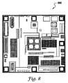
図8は、適応ホールIC 800のブロック図を示し、これは本発明の代替実施形態によって実施され得る。適応ホールIC 800は、図1のシステム100を実施するのに利用され得る。一般に、システム100およびIC 800は、例えばカムターゲット302および304などのカムターゲットに優れた精度(例えば±1.25°未満)を与える適応ホールセンサとして機能することができる。システム100およびIC 800の適応ホールセンサは、ほとんどのカム対象物向けのTPOならびに精度および空隙性能を最適化するために特定のターゲットに適合するように調節され得るスライスレベル(すなわち切換えレベル)を提供する。システム100は「捩れ」に感応せず、また逆電圧保護および出力短絡保護を利用して機能することができる。
FIG. 8 shows a block diagram of an
本明細書で説明された実施形態および例は、本発明およびその実用化について最も良く説明し、それによって当業者が本発明を作成し利用することを可能にするために示されるものである。しかし、上記説明および例は、説明および例のみの目的で示されたものであることを当業者なら理解するであろう。本発明の他の変形形態および変更形態は、当業者には明白であろう。また、そのような変形形態および変更形態が対象として含まれることが添付の特許請求の範囲の意図である。 The embodiments and examples described herein are presented to best explain the invention and its practical application, thereby enabling those skilled in the art to make and use the invention. However, one of ordinary skill in the art will appreciate that the above description and examples have been presented for purposes of illustration and example only. Other variations and modifications of the invention will be apparent to those skilled in the art. In addition, it is the intent of the appended claims to include such variations and modifications.
説明された記述は、網羅的であるか、または本発明の範囲を限定するようには意図されていない。上記の教示に照らして、添付の特許請求の範囲から逸脱することなしに、多くの変更形態および変形形態が可能である。本発明の使用は、様々な特性を有する構成要素を含むことができるように企図されている。本発明の範囲が、本明細書に添付の特許請求の範囲によって定義され、等価物に対してすべての点で十分な認識を与えることが意図されている。 The description as set forth is not intended to be exhaustive or to limit the scope of the invention. Many modifications and variations are possible in light of the above teaching without departing from the scope of the appended claims. It is contemplated that the use of the present invention can include components having various characteristics. The scope of the present invention is defined by the claims appended hereto, and is intended to provide full appreciation for the equivalents in all respects.
排他的な特性または権利が請求される本発明の実施形態が、特許請求の範囲に示されるように定義される。 Embodiments of the invention in which an exclusive property or right is claimed are defined as set forth in the claims.
Claims (25)
歯検出器およびスロット検出器を備え、前記バイアス磁石および前記回転ターゲットによって生成された前記磁気信号の正および負のピークを検出するデュアルピーク検出器と、
前記デュアルピーク検出器の前記歯検出器に対し最小値を設定し、前記デュアルピーク検出器の前記スロット検出器に対し最大値を設定することにより真のパワーオン(TPO)機能性が得られるように前記デュアルピーク検出器と関連し、それによって前記検出システムに電力が供給されると直ちに前記回転ターゲットが検出される、前記TPO機能性をもたらすクランプ回路と、
を備える検出システム。 A rotating target associated with a bias magnet having a magnetic field, and the bias magnet and the rotating target generate magnetic signals having positive and negative peaks;
A dual peak detector comprising a tooth detector and a slot detector for detecting positive and negative peaks of the magnetic signal generated by the bias magnet and the rotating target;
By setting a minimum value for the tooth detector of the dual peak detector and setting a maximum value for the slot detector of the dual peak detector, true power on (TPO) functionality can be obtained. A clamping circuit for providing said TPO functionality, associated with said dual peak detector, whereby said rotating target is detected as soon as power is supplied to said detection system;
A detection system comprising:
歯検出器およびスロット検出器を備え、前記バイアス磁石および前記回転ターゲットによって生成された前記磁気信号の正および負のピークを検出するデュアルピーク検出器と、
前記デュアルピーク検出器の前記ピーク検出器に対し最小値を設定し、前記デュアルピーク検出器の前記スロット検出器に対し最大値を設定することにより真のパワーオン(TPO)機能性が得られるように前記歯検出器およびスロット検出器と関連する、前記TPO機能性をもたらすクランプ回路と、
前記デュアルピーク検出器の前記歯検出器に対し前記最小値を保持し、かつ前記デュアルピーク検出器の前記スロット検出器に対し前記最大値を保持することにより、前記センサに電力が供給されると前記回転ターゲットが直ちに検出される、前記クランプ回路に関連する少なくとも1つのコンデンサと、
を備える検出システム。 A rotating target associated with a bias magnet, the bias magnet and the rotating target generating a magnetic signal having positive and negative peaks, comprising a plurality of teeth and at least one slot and at least one tooth of the plurality of teeth ,
A dual peak detector comprising a tooth detector and a slot detector for detecting positive and negative peaks of the magnetic signal generated by the bias magnet and the rotating target;
A true power-on (TPO) functionality can be obtained by setting a minimum value for the peak detector of the dual peak detector and a maximum value for the slot detector of the dual peak detector. A clamping circuit for providing said TPO functionality associated with said tooth detector and slot detector;
When the sensor is powered by holding the minimum value for the tooth detector of the dual peak detector and holding the maximum value for the slot detector of the dual peak detector At least one capacitor associated with the clamping circuit, wherein the rotating target is immediately detected;
A detection system comprising:
前記デュアルピーク検出器に関連付けられた切換えレベルは、前記バイアス磁石および前記回転ターゲットによって生成された前記磁気信号の前記正および負のピークのほぼ30%からほぼ70%で前記ICに調整される、請求項12に記載のシステム。 A DC coupled switch point circuit for communicating a calibration position of the bias magnet disposed in an integrated circuit (IC) in association with the bias magnet, the dual peak detector, and the clamp circuit;
The switching level associated with the dual peak detector is adjusted to the IC at approximately 30% to approximately 70% of the positive and negative peaks of the magnetic signal generated by the bias magnet and the rotating target. The system of claim 12.
前記バイアス磁石および前記回転ターゲットによって生成された前記磁気信号の正および負のピークを検出する、歯検出器およびスロット検出器を備えるデュアルピーク検出器を設けるステップと、
真のパワーオン(TPO)機能性をもたらすことができるクランプ回路を前記デュアルピーク検出器に関連付けるステップと、
前記デュアルピーク検出器の前記歯検出器に対し最小値を設定し、かつ前記デュアルピーク検出器の前記スロット検出器に対し最大値を設定することにより前記TPO機能性を得るステップと、これにより前記センサに電力が供給されると直ちに前記回転ターゲットが検出される、
各ステップを含む、回転ターゲットを検出するための方法。 Associating a bias magnet with a rotating target; and generating a magnetic signal having positive and negative peaks at the bias magnet and the rotating target;
Providing a dual peak detector comprising a tooth detector and a slot detector for detecting positive and negative peaks of the magnetic signal generated by the bias magnet and the rotating target;
Associating a clamping circuit capable of providing true power-on (TPO) functionality with the dual peak detector;
Obtaining the TPO functionality by setting a minimum value for the tooth detector of the dual peak detector and setting a maximum value for the slot detector of the dual peak detector; The rotating target is detected as soon as power is supplied to the sensor;
A method for detecting a rotating target, comprising each step.
Applications Claiming Priority (2)
| Application Number | Priority Date | Filing Date | Title |
|---|---|---|---|
| US11/003,845 US6967477B1 (en) | 2004-12-02 | 2004-12-02 | Adaptive geartooth sensor with dual peak detectors and true power on capability |
| PCT/US2005/043478 WO2006060577A1 (en) | 2004-12-02 | 2005-12-01 | Adaptive geartooth sensor with dual peak detectors and true power on capability |
Publications (2)
| Publication Number | Publication Date |
|---|---|
| JP2008522197A true JP2008522197A (en) | 2008-06-26 |
| JP2008522197A5 JP2008522197A5 (en) | 2008-08-21 |
Family
ID=35344903
Family Applications (1)
| Application Number | Title | Priority Date | Filing Date |
|---|---|---|---|
| JP2007544511A Withdrawn JP2008522197A (en) | 2004-12-02 | 2005-12-01 | Adaptive gear tooth sensor with dual peak detector and true power-on capability |
Country Status (5)
| Country | Link |
|---|---|
| US (1) | US6967477B1 (en) |
| EP (1) | EP1817548B1 (en) |
| JP (1) | JP2008522197A (en) |
| CN (1) | CN101111744A (en) |
| WO (1) | WO2006060577A1 (en) |
Cited By (1)
| Publication number | Priority date | Publication date | Assignee | Title |
|---|---|---|---|---|
| KR20140140572A (en) * | 2012-03-06 | 2014-12-09 | 알레그로 마이크로시스템스, 엘엘씨 | Magnetic field sensor for sensing rotation of an object |
Families Citing this family (8)
| Publication number | Priority date | Publication date | Assignee | Title |
|---|---|---|---|---|
| US7362094B2 (en) * | 2006-01-17 | 2008-04-22 | Allegro Microsystems, Inc. | Methods and apparatus for magnetic article detection |
| FR2978833B1 (en) | 2011-08-04 | 2014-05-02 | Continental Automotive France | AUTOMATIC CALIBRATION METHOD OF CAMSHAFT SENSOR FOR MOTOR VEHICLE |
| US9638548B2 (en) | 2012-05-07 | 2017-05-02 | Infineon Technologies Ag | Output switching systems and methods for magnetic field sensors |
| US10408892B2 (en) * | 2013-07-19 | 2019-09-10 | Allegro Microsystems, Llc | Magnet with opposing directions of magnetization for a magnetic sensor |
| US10102992B2 (en) | 2014-02-25 | 2018-10-16 | Infineon Technologies Ag | Switching apparatus, switching system and switching method |
| FR3041426B1 (en) * | 2015-09-18 | 2019-03-22 | Continental Automotive France | AUTOMATIC CALIBRATION METHOD OF CAMSHAFT SENSOR FOR MOTOR VEHICLE ENGINE |
| US10338642B2 (en) | 2016-05-20 | 2019-07-02 | Honeywell International Inc. | Hall switch with adaptive threshold |
| DE102019216292A1 (en) * | 2019-10-23 | 2021-04-29 | Robert Bosch Gmbh | Method for evaluating signals from a camshaft sensor |
Family Cites Families (14)
| Publication number | Priority date | Publication date | Assignee | Title |
|---|---|---|---|---|
| US5469054A (en) | 1993-04-22 | 1995-11-21 | Honeywell Inc. | Position sensor with two magnetically sensitive devices and two target tracks which are sensed in combination with each other to provide a synthesized signal |
| JPH08105707A (en) * | 1994-10-06 | 1996-04-23 | Nippondenso Co Ltd | Rotational position detector |
| US6297627B1 (en) * | 1996-01-17 | 2001-10-02 | Allegro Microsystems, Inc. | Detection of passing magnetic articles with a peak-to-peak percentage threshold detector having a forcing circuit and automatic gain control |
| US5698777A (en) | 1996-02-05 | 1997-12-16 | Ford Motor Company | Camshaft revolution sensing assembly |
| US5777465A (en) | 1996-02-16 | 1998-07-07 | Analog Devices, Inc. | Circuitry and method for sensing spatial transitions sensed with a magnetic sensor |
| US5694040A (en) | 1996-07-02 | 1997-12-02 | Honeywell Inc. | Magnetic sensor circuit with two magnetically sensitive devices |
| US5867021A (en) | 1997-02-11 | 1999-02-02 | Hancock; Peter G. | Method and apparatus for sensing the position of a ferromagnetic object |
| US6073713A (en) | 1998-03-25 | 2000-06-13 | Ford Global Technologies, Inc. | Crankshaft position sensing with combined starter alternator |
| JP3799270B2 (en) * | 2001-12-21 | 2006-07-19 | 株式会社日立製作所 | Control device for switching the driving state of an automobile |
| US6597205B2 (en) | 2001-12-21 | 2003-07-22 | Honeywell International Inc. | High accuracy method for determining the frequency of a pulse input signal over a wide frequency range |
| EP1472547B1 (en) * | 2002-02-05 | 2017-04-19 | Allegro Microsystems, LLC | Peak-to-peak signal detector |
| US6759843B2 (en) | 2002-11-15 | 2004-07-06 | Honeywell International Inc. | Sensing methods and systems for hall and/or MR sensors |
| US7026897B2 (en) | 2003-01-03 | 2006-04-11 | Honeywell International Inc. | Multiple output magnetic sensor |
| US6727689B1 (en) | 2003-07-24 | 2004-04-27 | Honeywell International Inc. | Magnetic-effect sensing apparatus with signal thresholding |
-
2004
- 2004-12-02 US US11/003,845 patent/US6967477B1/en active Active
-
2005
- 2005-12-01 WO PCT/US2005/043478 patent/WO2006060577A1/en active Application Filing
- 2005-12-01 EP EP05852642.7A patent/EP1817548B1/en active Active
- 2005-12-01 JP JP2007544511A patent/JP2008522197A/en not_active Withdrawn
- 2005-12-01 CN CNA2005800476553A patent/CN101111744A/en active Pending
Cited By (3)
| Publication number | Priority date | Publication date | Assignee | Title |
|---|---|---|---|---|
| KR20140140572A (en) * | 2012-03-06 | 2014-12-09 | 알레그로 마이크로시스템스, 엘엘씨 | Magnetic field sensor for sensing rotation of an object |
| JP2015513091A (en) * | 2012-03-06 | 2015-04-30 | アレグロ・マイクロシステムズ・エルエルシー | Magnetic field sensor for detecting the rotation of an object |
| KR102043035B1 (en) * | 2012-03-06 | 2019-11-11 | 알레그로 마이크로시스템스, 엘엘씨 | Magnetic field sensor for sensing rotation of an object |
Also Published As
| Publication number | Publication date |
|---|---|
| CN101111744A (en) | 2008-01-23 |
| EP1817548A1 (en) | 2007-08-15 |
| EP1817548B1 (en) | 2015-06-03 |
| WO2006060577A1 (en) | 2006-06-08 |
| US6967477B1 (en) | 2005-11-22 |
Similar Documents
| Publication | Publication Date | Title |
|---|---|---|
| JP2008522197A (en) | Adaptive gear tooth sensor with dual peak detector and true power-on capability | |
| US6291989B1 (en) | Differential magnetic position sensor with adaptive matching for detecting angular position of a toothed target wheel | |
| EP2391903B1 (en) | Magnetic field detector having a variable threshold | |
| US6400142B1 (en) | Steering wheel position sensor | |
| US7141964B2 (en) | Adaptive integrated circuit for magnetoresistive sensors | |
| EP2997390A1 (en) | Magnetic field sensor for detecting a magnetic field in any direction above thresholds | |
| JP3011774B2 (en) | Method for setting switching point in sensor output signal | |
| US10852328B2 (en) | Zero-crossing detection circuit and sensor device | |
| US6232770B1 (en) | Low cost single magnetoresistor position and speed sensor | |
| TWI670472B (en) | Zero-crossing detection circuit and sensing device | |
| JP3336668B2 (en) | Sensor signal processing device | |
| US10746572B2 (en) | Rotation detection device | |
| JP2011117731A (en) | Magnetic detection device | |
| US6954063B2 (en) | Motion detecting device using magnetoresistive unit | |
| US7323864B2 (en) | Absolute angular position sensor on 360 of a rotating element | |
| JP2007303925A (en) | Failure detection circuit of noncontact sensor | |
| JP4521808B2 (en) | Encoder | |
| CN110398623B (en) | Zero-cross detection circuit and sensor device | |
| JP3326933B2 (en) | Sensor signal processing device | |
| KR100417144B1 (en) | Rotation angle detecting device | |
| JP6056653B2 (en) | Rotation sensor | |
| JP2000337922A (en) | Rotation detecting device | |
| JPH11211740A (en) | Electromagnetic pickup sensor | |
| CN114551715A (en) | Signal processing circuit, signal processing method thereof and Hall sensing circuit | |
| JP2004245766A (en) | Device for detecting rotation angle |
Legal Events
| Date | Code | Title | Description |
|---|---|---|---|
| A521 | Written amendment |
Free format text: JAPANESE INTERMEDIATE CODE: A523 Effective date: 20080701 |
|
| A621 | Written request for application examination |
Free format text: JAPANESE INTERMEDIATE CODE: A621 Effective date: 20080701 |
|
| A761 | Written withdrawal of application |
Free format text: JAPANESE INTERMEDIATE CODE: A761 Effective date: 20081020 |