EP1817548B1 - Adaptive geartooth sensor with dual peak detectors and true power on capability - Google Patents
Adaptive geartooth sensor with dual peak detectors and true power on capability Download PDFInfo
- Publication number
- EP1817548B1 EP1817548B1 EP05852642.7A EP05852642A EP1817548B1 EP 1817548 B1 EP1817548 B1 EP 1817548B1 EP 05852642 A EP05852642 A EP 05852642A EP 1817548 B1 EP1817548 B1 EP 1817548B1
- Authority
- EP
- European Patent Office
- Prior art keywords
- detector
- dual peak
- tooth
- peak detector
- slot
- Prior art date
- Legal status (The legal status is an assumption and is not a legal conclusion. Google has not performed a legal analysis and makes no representation as to the accuracy of the status listed.)
- Active
Links
Images


Classifications
-
- G—PHYSICS
- G01—MEASURING; TESTING
- G01D—MEASURING NOT SPECIALLY ADAPTED FOR A SPECIFIC VARIABLE; ARRANGEMENTS FOR MEASURING TWO OR MORE VARIABLES NOT COVERED IN A SINGLE OTHER SUBCLASS; TARIFF METERING APPARATUS; MEASURING OR TESTING NOT OTHERWISE PROVIDED FOR
- G01D5/00—Mechanical means for transferring the output of a sensing member; Means for converting the output of a sensing member to another variable where the form or nature of the sensing member does not constrain the means for converting; Transducers not specially adapted for a specific variable
- G01D5/12—Mechanical means for transferring the output of a sensing member; Means for converting the output of a sensing member to another variable where the form or nature of the sensing member does not constrain the means for converting; Transducers not specially adapted for a specific variable using electric or magnetic means
- G01D5/14—Mechanical means for transferring the output of a sensing member; Means for converting the output of a sensing member to another variable where the form or nature of the sensing member does not constrain the means for converting; Transducers not specially adapted for a specific variable using electric or magnetic means influencing the magnitude of a current or voltage
- G01D5/142—Mechanical means for transferring the output of a sensing member; Means for converting the output of a sensing member to another variable where the form or nature of the sensing member does not constrain the means for converting; Transducers not specially adapted for a specific variable using electric or magnetic means influencing the magnitude of a current or voltage using Hall-effect devices
- G01D5/145—Mechanical means for transferring the output of a sensing member; Means for converting the output of a sensing member to another variable where the form or nature of the sensing member does not constrain the means for converting; Transducers not specially adapted for a specific variable using electric or magnetic means influencing the magnitude of a current or voltage using Hall-effect devices influenced by the relative movement between the Hall device and magnetic fields
-
- G—PHYSICS
- G01—MEASURING; TESTING
- G01D—MEASURING NOT SPECIALLY ADAPTED FOR A SPECIFIC VARIABLE; ARRANGEMENTS FOR MEASURING TWO OR MORE VARIABLES NOT COVERED IN A SINGLE OTHER SUBCLASS; TARIFF METERING APPARATUS; MEASURING OR TESTING NOT OTHERWISE PROVIDED FOR
- G01D18/00—Testing or calibrating apparatus or arrangements provided for in groups G01D1/00 - G01D15/00
- G01D18/001—Calibrating encoders
-
- G—PHYSICS
- G01—MEASURING; TESTING
- G01D—MEASURING NOT SPECIALLY ADAPTED FOR A SPECIFIC VARIABLE; ARRANGEMENTS FOR MEASURING TWO OR MORE VARIABLES NOT COVERED IN A SINGLE OTHER SUBCLASS; TARIFF METERING APPARATUS; MEASURING OR TESTING NOT OTHERWISE PROVIDED FOR
- G01D5/00—Mechanical means for transferring the output of a sensing member; Means for converting the output of a sensing member to another variable where the form or nature of the sensing member does not constrain the means for converting; Transducers not specially adapted for a specific variable
- G01D5/12—Mechanical means for transferring the output of a sensing member; Means for converting the output of a sensing member to another variable where the form or nature of the sensing member does not constrain the means for converting; Transducers not specially adapted for a specific variable using electric or magnetic means
- G01D5/14—Mechanical means for transferring the output of a sensing member; Means for converting the output of a sensing member to another variable where the form or nature of the sensing member does not constrain the means for converting; Transducers not specially adapted for a specific variable using electric or magnetic means influencing the magnitude of a current or voltage
- G01D5/142—Mechanical means for transferring the output of a sensing member; Means for converting the output of a sensing member to another variable where the form or nature of the sensing member does not constrain the means for converting; Transducers not specially adapted for a specific variable using electric or magnetic means influencing the magnitude of a current or voltage using Hall-effect devices
- G01D5/147—Mechanical means for transferring the output of a sensing member; Means for converting the output of a sensing member to another variable where the form or nature of the sensing member does not constrain the means for converting; Transducers not specially adapted for a specific variable using electric or magnetic means influencing the magnitude of a current or voltage using Hall-effect devices influenced by the movement of a third element, the position of Hall device and the source of magnetic field being fixed in respect to each other
-
- G—PHYSICS
- G01—MEASURING; TESTING
- G01D—MEASURING NOT SPECIALLY ADAPTED FOR A SPECIFIC VARIABLE; ARRANGEMENTS FOR MEASURING TWO OR MORE VARIABLES NOT COVERED IN A SINGLE OTHER SUBCLASS; TARIFF METERING APPARATUS; MEASURING OR TESTING NOT OTHERWISE PROVIDED FOR
- G01D5/00—Mechanical means for transferring the output of a sensing member; Means for converting the output of a sensing member to another variable where the form or nature of the sensing member does not constrain the means for converting; Transducers not specially adapted for a specific variable
- G01D5/12—Mechanical means for transferring the output of a sensing member; Means for converting the output of a sensing member to another variable where the form or nature of the sensing member does not constrain the means for converting; Transducers not specially adapted for a specific variable using electric or magnetic means
- G01D5/244—Mechanical means for transferring the output of a sensing member; Means for converting the output of a sensing member to another variable where the form or nature of the sensing member does not constrain the means for converting; Transducers not specially adapted for a specific variable using electric or magnetic means influencing characteristics of pulses or pulse trains; generating pulses or pulse trains
- G01D5/24471—Error correction
- G01D5/2448—Correction of gain, threshold, offset or phase control
-
- G—PHYSICS
- G01—MEASURING; TESTING
- G01D—MEASURING NOT SPECIALLY ADAPTED FOR A SPECIFIC VARIABLE; ARRANGEMENTS FOR MEASURING TWO OR MORE VARIABLES NOT COVERED IN A SINGLE OTHER SUBCLASS; TARIFF METERING APPARATUS; MEASURING OR TESTING NOT OTHERWISE PROVIDED FOR
- G01D5/00—Mechanical means for transferring the output of a sensing member; Means for converting the output of a sensing member to another variable where the form or nature of the sensing member does not constrain the means for converting; Transducers not specially adapted for a specific variable
- G01D5/12—Mechanical means for transferring the output of a sensing member; Means for converting the output of a sensing member to another variable where the form or nature of the sensing member does not constrain the means for converting; Transducers not specially adapted for a specific variable using electric or magnetic means
- G01D5/244—Mechanical means for transferring the output of a sensing member; Means for converting the output of a sensing member to another variable where the form or nature of the sensing member does not constrain the means for converting; Transducers not specially adapted for a specific variable using electric or magnetic means influencing characteristics of pulses or pulse trains; generating pulses or pulse trains
- G01D5/24471—Error correction
- G01D5/2449—Error correction using hard-stored calibration data
Definitions
- Embodiments are generally related to sensor devices, methods and systems. Embodiments are also related to cam and crankshaft sensors utilized in automotive applications. Embodiments are additionally related to Hall devices and True Power On (TPO) applications and capabilities.
- TPO True Power On
- Various sensors are known in the magnetic-effect sensing arts. Examples of common magnetic-effect sensors include Hall effect and magnetoresistive technologies. Such magnetic sensors generally respond to a change in the magnetic field as influenced by the presence or absence of a ferromagnetic target object of a designed shape passing through the sensory field of the magnetic-effect sensor. The sensor can then provide an electrical output, which can be further modified as necessary by subsequent electronics to yield sensing and control information. The subsequent electronics may be located either onboard or outboard of the sensor package.
- sensors utilized in automotive applications are configured as position sensors, which provide feedback to a control unit.
- Many of these types of sensors and related systems are mechanical in nature and are very sensitive to the wearing of contacts, contact contamination, and so forth.
- designers have searched for noncontacting electrical solutions provided by magnetoresistive and/or Hall-effect technologies, which have attempted to detect variance in a magnetic field.
- One of the primary problems with this approach is the inability of such systems to accurately detect position. The accuracy requirement of such systems makes it difficult, for example, to use a single Hall element because of the offset and shifts over temperature.
- Positions sensors must meet high repeatability requirements for both camshaft and crankshaft applications in automotive devices.
- camshaft sensors for newly developed engines require tighter accuracy over all environmental conditions and the ability to determine if the sensor is sensing a target tooth or a target slot as soon as power is applied (i.e., "True Power On” or TPO).
- TPO Truste Power On
- Such features allow the engine to be activated sooner and run more efficiently.
- the present inventor has thus concluded that a need exists for an improved adaptive sensing method and system that can provide high accuracy and highly repeatable switch points through a complete RPM range.
- the present invention is therefore directed toward improved magnetic sensing methods and systems.
- US patent 5867021 discloses a method and apparatus for sensing the position of a ferromagnetic object.
- a magnetic sensor is operated by a method which provides a magnetic field extending through a preselected detection zone.
- a permanent magnet can be used to provide the magnetic field.
- the method disposes a magnetically sensitive component within the magnetic field and the magnetically sensitive component, such as a Hall effect element, provides a first signal that is responsive to a portion of the magnetic field imposed on the magnetically sensitive component.
- the sensor also determines a base value and measures a maximum magnitude of the first signal during a preselected period of time, such as the time required for a gear to rotate so that all of its ferromagnetic teeth pass through the detection zone.
- the sensor also determines a reference value as a function of the base value and the maximum magnitude.
- the sensor compares the first signal to the reference value and provides a second signal that is a function of the relative magnitudes of the first signal and the reference value, whereby the second signal is representative of the position of the ferromagnetic object relative to the detection zone.
- US patent 5777465 discloses a circuit for use with a magnetic sensing device having at least first and second sensors has a summing amplifier for providing a difference signal and a peak detector for detecting peaks in the difference signal. The peaks determine a spatial offset of a transition in a sensed body.
- the present invention provides for a sensing system and corresponding method as claimed in the accompanying claims.
- FIG. 1(a) illustrates a schematic diagram of a dual-detector system, which can be implemented in accordance with a preferred embodiment
- FIG. 1 (b) illustrates a schematic diagram of a dual peak detector that can be adapted for utilization with the dual-detector system depicted in FIG. 1(a) in accordance with a preferred embodiment
- FIG. 2 illustrates a graph generally indicating switching tolerances
- FIG. 3 illustrates cam targets, which can be utilized in accordance with a preferred embodiment
- FIG. 4 illustrates a graph depicting signal levels at power-up with positive and negative Gauss signals in accordance with one embodiment
- FIG. 5 illustrates a block diagram of an adaptive Hall sensor configuration, which can be adapted for use in accordance with a preferred embodiment
- FIG. 6 illustrates a graph depicting an exemplary adaptive Hall-effect sensor magnetic field in accordance with a preferred embodiment.
- FIG. 7 illustrates a graph depicting adaptive Hall accuracy as a function of frequency and switching points, in accordance with a preferred embodiment.
- FIG. 8 illustrates an image of the adaptive Hall embodiment as an integrated circuit (IC), in accordance with the preferred embodiment.
- IC integrated circuit
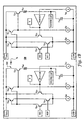
- FIG. 1(a) illustrates a block diagram of a dual-detector system 100, which can be implemented in accordance with a preferred embodiment of the present invention.
- FIG. 1(b) illustrates a schematic diagram of a dual peak detector 130 that can be adapted for utilization with the dual-detector system depicted in FIG. 1(a) in accordance with a preferred embodiment. Note that in FIGS. 1(a) and 1(b) , identical or similar parts are generally indicated by identical reference numerals.
- System 100 generally includes a sensing element 102, which can be associated with and/or interact with a rotating target and biasing magnet, such as, for example, targets 220, 218 and/or 224 depicted in FIG. 2 .
- the biasing magnet 508 possesses a magnet field such that the biasing magnet 508 and the rotating target generate a magnetic signal having positive and negative peaks thereof.
- System 100 further includes a signal amplifying circuit 104 used to amplify and condition the input signals from the sense element 102 and a voltage reference generator 107. Circuit 104 can be used to amplify and shift the signals to an appropriate level.
- System 100 also includes dual peak detector 130 (which is shown in greater detail in FIG. 1(b) ) that is configured to include a tooth detector 108 and a slot detector 110, wherein the dual peak detectors 108 and 110 detect positive and negative peaks of the magnetic signal generated by the biasing magnet, the sensing element 102 and the rotating target.
- dual peak detector 130 which is shown in greater detail in FIG. 1(b)
- the dual peak detectors 108 and 110 detect positive and negative peaks of the magnetic signal generated by the biasing magnet, the sensing element 102 and the rotating target.
- rotating targets which can be detected by system 100, cam targets 302 and 304 illustrated in FIG. 3 .
- Tooth detector 108 and slot detector 110 further includes clamping circuits that provides a true power on (TPO) functionality, wherein the clamping circuit is associated with the dual peak detector 130, such that the TPO functionality is obtained by setting a minimum value for the peak detector 108 of the dual peak detector 130 and a maximum value for the slot detector 110 of the dual peak detector 130, thereby permitting the rotating target to be sensed as soon as power is applied to rotate the rotating target.
- TPO true power on
- the sense element 102 can be implemented as a Hall magnetic device or another magnetoresistive device.
- Sense element 102 can be connected to an amplifier 104, which can function as a variable amplifier.
- the output from amplifier 104 can be coupled to a voltage reference circuit 107.
- Sig - Ref B*K* Sens, where K is a gain term, and Sens represents the sensitivity of the sense element and B is the applied magnetic field.
- the value of B crosses through a particular value, Bo, situated between the minimum tooth and maximum slot values of the magnetic signal.
- the voltage signal on Node 1 crosses the reference voltage on Node 2 as the magnetic signal moves between it's tooth and slot values.
- Nodes 1 and 2 carry the signal and reference voltages to the inputs of the dual peak detector system 130 depicted in FIG. 1(b) . It can be appreciated from FIG. 1 (b) that if the signal voltage (Sig) is less than the reference voltage (Ref) then Q41 is reverse biased and negative feedback will cause the differential stage Q42, Q43 to balance. Thus, T (and Tooth Cap) can attain a value equal to Ref.
- capacitors 135 and 137 can be utilized to capture the positive and negative peaks of waveforms. Very small discharge currents are incorporated to ensure that the capacitor voltages decay in an appropriate fashion.
- the dual peak detector outputs S and T are connected to a trim network 133.
- Resistors 114 and 116 function series with one another and are tied to one another at Node 3, which in turn is connected to an input (i.e., "Slice") of a calibration comparator 117 and an input (i.e., "Slice”) of an output comparator circuit 118.
- resistors 114 and 116 are trimmed such that the voltage on Node 3 (i.e., Slice) is a certain fraction of the difference between T and S.
- a second input (i.e., Sig) of calibration comparator circuit 117 and a second input (i.e., Sig) of output comparator circuit 118 are both connected to the signal voltage on Node 1.
- the slice input of the calibration comparator can be connected to Node 2 (i.e., ref voltage).
- Hysteresis is included in the comparator circuits 117 and 118 to prevent chattering and false triggering associated with noise and slowly varying inputs.
- System 100 can also include a voltage regulation stage 122 and an output driver 120 to properly match the application requirements.
- Output stage 120 may be configured as an open collector stage and may include a means to protect the circuitry against accidental shorting.
- Regulator 122 may include means for protecting system 100 from over-voltage or reverse supply conditions.
- system 100 utilizes dual peak detector 130 to find both the positive and the negative peaks of the magnetic signal generated by the biasing magnet, sense element 102 and the rotating target. Such tooth/slot values can be maintained with an external capacitor, such as, for example capacitors 135 and/or 137 in conjunction with Buffer Amplifiers 136 and 138.
- System 100 can be implemented in the context of an integrated circuit (IC). The switching level of system 100 can be trimmed into such an IC at approximately 30% to 70% of these peaks, depending on the target configuration. In the preferred embodiment then, the magnetic signal, Sig varies around the recovered slicing level, Slice. Comparator 118 transmits this information to the output. This aspect of system 100 provides high accuracy and repeatability.
- the TPO functionality can be obtained by setting a minimum value for the tooth detector 108 and a maximum value for the slot detector 110.
- a tooth i.e., a target
- the tooth detector 108 will be at a high magnetic field (i.e., depending on the air gap, which for estimation purposes may be approximately 0.02 Tesla / 200 Gauss)
- the slot detector 110 will be clamped to the reference voltage, which in the preferred embodiment represents zero Tesla / Gauss.
- Such a calculation positions the operation point at approximately 0.01 Tesla / 100 gauss if the switching level is trimmed at 50%.
- System 100 will then recognize that a tooth is present as Sig > Slice.
- System 100 can therefore transmit information beginning with a feature of a rotating target having a plurality of teeth and slots formed there between.
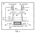
- FIG. 2 illustrates a graph 200 generally indicating switching tolerances.
- Graph 200 indicates an operate accuracy 216 and a release accuracy 204 which are located at opposing ends of a digital output signal 202, which corresponds approximately with the length of a target 218 of a rotating target.
- Operate refers to the slot to tooth transition
- Release refers to the tooth to slot transition.
- Target 218 is a tooth, while targets 220 and 224 comprise slots formed at either side of target 218 (i.e., the tooth).
- Target rotation is generally indicated by arrow 226.
- a hard edge offset 210 can be located to the left of analog output signal 206.
- a hard edge offset 208 can be located to the right of analog output signal 206.
- An operate voltage 212 and a release voltage 214 are also depicted in graph 200.
- Vrel Sig-Hyst. Note that graph 200 is not considered a limiting feature of the present invention, but is presented for generally illustrative and edification purposes only.
- FIG. 3 illustrates examples of cam targets 302 and 304, which can be utilized in accordance with a preferred embodiment.
- Cam targets 302 and 304 are examples of rotating targets which can be detected by system 100 illustrated in FIG. 1 (a) in associate with the configuration depicted in FIG. 1 (b) .
- Cam target 304 for example, includes one or more teeth 304, 306, 308 and 310 of varying size and shape.
- a slot 305 can be formed between tooth 304 and 305.
- a slot 307 can be formed between tooth 306 and 308.
- a slot 309 can be formed between tooth 308 and 310.
- a slot 311 can be formed between tooth 310 and 304.
- cam target 304 can be implemented as a rotating target that includes a plurality of teeth and respective slots formed therebetween.
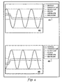
- FIG. 4 illustrates a graph 402 depicting signal levels at power- up with a positive magnetic flux density signal and a graph 406 depicting signal levels at power-up with a negative Gauss signal in accordance with one embodiment.
- Graph 402 is generally associated with a legend 404 depicting a Signal, Tooth cap, Slot cap, slicing level, operate and release levels.
- Graph 406 is associated with a similar legend 408.
- a tooth cap signal matches a transducer signal, and a slot cap signal clamps at zero Tesla / Gauss.
- the initial slicing level is determined by these levels, and the device is initially operated, since the signal level is above the operate level.
- the slot cap signal tracks the transducer signal until the lowest point is reached, and the tooth cap signal may decay towards, but not less than, zero.
- the Sig level will fall below the release value and the circuit will release.
- the slicing level adjusts accordingly.
- the slot cap signal matches the transducer signal, and the tooth cap signal clamps at zero Tesla / Gauss.
- the initial slicing level is determined by these levels, and the device is initially released, since the signal level is below the release level.
- the tooth cap signal tracks the transducer signal until the highest point is reached and the slot cap signal may decay towards, but not greater than, zero.
- the Sig level will rise above the operate value and the circuit will operate.
- the tooth and slot cap signals reach their steady state values, the slicing level adjusts accordingly.
- FIG. 5 illustrates a block diagram of an adaptive Hall sensor configuration 500, which can be adapted for use in accordance with a preferred embodiment.
- Configuration 500 can be implemented in the context of a sensor package 501.
- a Hall element 506 can be disposed a length L 2 from the package face 502.
- the center of Hall element 506 can be disposed a width W 3 from the center of package 501.
- a magnet 508 can be disposed a width W 2 from the center of package 501.
- Magnet 508 generally possesses a width W 1 and a length L 1 .
- a magnet calibration position 510 is also noted in configuration 500.
- FIG. 6 illustrates a graph 600 depicting an exemplary adaptive Hall sensor magnetic field in accordance with a preferred embodiment.
- Graph 600 generally indicates an adaptive Hall sensor magnetic field at 25°C with a cam target, such as, for example cam targets 302 and 304 depicted in FIG. 3 .
- Such an adaptive Hall sensor magnetic field can be implemented via, for example, biasing magnet 102 depicted in FIG. 1 in association with system 100 thereof.
- a legend 602 is associated with graph 600 and includes varying air gap lengths. Respective data indicative of magnetic field (i.e., magnetic flux density in Tesla) versus target rotation (in degrees) is depicted in graph 600.
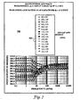
- FIG. 7 illustrates graph 700 depicting adaptive hall accuracy as a function of frequency and switching points, in accordance with a preferred embodiment.
- the data indicated in graph 700 can be generated via system 100 of FIG. 1 .
- Graph 700 illustrates adaptive Hall accuracy generated by system 100 in association with a rotating target at 25°C, +/-20 G peak limits, 50%, 0.1 uF capacitors (e.g., capacitors 137 and 135 of FIG. 1 ) and +/- 15 G Hyst.
- a legend 702 is associated with graph 700, which plots switching point in degrees versus frequency (RPM).
- FIG. 8 illustrates a block diagram of an adaptive Hall IC 800, which can be implemented in accordance with an alternative embodiment of the present invention.
- Adaptive Hall IC 800 can be utilized to implement system 100 of FIG. 1 .
- system 100 and IC 800 can function as an adaptive Hall sensor that offers excellent accuracy (e.g., less than +/- 1.25°C) on cam targets, such as, for example, cam targets 302 and 304.
- the adaptive Hall sensor of system 100 and IC 800 offers TPO for most cam targets and a slice level (i.e. switching level) that can be adjusted to suit a specific target to optimize accuracy and air gap performance.
- System 100 is "twist" insensitive and can function utilizing a reverse voltage and output short circuit protection.
Landscapes
- Physics & Mathematics (AREA)
- General Physics & Mathematics (AREA)
- Transmission And Conversion Of Sensor Element Output (AREA)
- Measuring Magnetic Variables (AREA)
Description
- Embodiments are generally related to sensor devices, methods and systems. Embodiments are also related to cam and crankshaft sensors utilized in automotive applications. Embodiments are additionally related to Hall devices and True Power On (TPO) applications and capabilities.
- Various sensors are known in the magnetic-effect sensing arts. Examples of common magnetic-effect sensors include Hall effect and magnetoresistive technologies. Such magnetic sensors generally respond to a change in the magnetic field as influenced by the presence or absence of a ferromagnetic target object of a designed shape passing through the sensory field of the magnetic-effect sensor. The sensor can then provide an electrical output, which can be further modified as necessary by subsequent electronics to yield sensing and control information. The subsequent electronics may be located either onboard or outboard of the sensor package.
- Many of the sensors utilized in automotive applications are configured as position sensors, which provide feedback to a control unit. Many of these types of sensors and related systems are mechanical in nature and are very sensitive to the wearing of contacts, contact contamination, and so forth. To help solve many of the warranty problems associated with mechanical sensors, designers have searched for noncontacting electrical solutions provided by magnetoresistive and/or Hall-effect technologies, which have attempted to detect variance in a magnetic field. One of the primary problems with this approach is the inability of such systems to accurately detect position. The accuracy requirement of such systems makes it difficult, for example, to use a single Hall element because of the offset and shifts over temperature.
- The difficulty with both Hall and magnetoresistive technologies is that high accuracy switching points at both low and high RPM's are difficult to achieve. Positions sensors must meet high repeatability requirements for both camshaft and crankshaft applications in automotive devices. In particular, camshaft sensors for newly developed engines require tighter accuracy over all environmental conditions and the ability to determine if the sensor is sensing a target tooth or a target slot as soon as power is applied (i.e., "True Power On" or TPO). Such features allow the engine to be activated sooner and run more efficiently. The present inventor has thus concluded that a need exists for an improved adaptive sensing method and system that can provide high accuracy and highly repeatable switch points through a complete RPM range. The present invention is therefore directed toward improved magnetic sensing methods and systems.
-
US patent 5867021 discloses a method and apparatus for sensing the position of a ferromagnetic object. In particular, a magnetic sensor is operated by a method which provides a magnetic field extending through a preselected detection zone. A permanent magnet can be used to provide the magnetic field. The method disposes a magnetically sensitive component within the magnetic field and the magnetically sensitive component, such as a Hall effect element, provides a first signal that is responsive to a portion of the magnetic field imposed on the magnetically sensitive component. The sensor also determines a base value and measures a maximum magnitude of the first signal during a preselected period of time, such as the time required for a gear to rotate so that all of its ferromagnetic teeth pass through the detection zone. The sensor also determines a reference value as a function of the base value and the maximum magnitude. The sensor compares the first signal to the reference value and provides a second signal that is a function of the relative magnitudes of the first signal and the reference value, whereby the second signal is representative of the position of the ferromagnetic object relative to the detection zone. -
US patent 5777465 discloses a circuit for use with a magnetic sensing device having at least first and second sensors has a summing amplifier for providing a difference signal and a peak detector for detecting peaks in the difference signal. The peaks determine a spatial offset of a transition in a sensed body. - The present invention provides for a sensing system and corresponding method as claimed in the accompanying claims.
- The accompanying figures, in which like reference numerals refer to identical or functionally-similar elements throughout the separate views and which are incorporated in and form a part of the specification, further illustrate the present invention and, together with the detailed description of the invention, serve to explain the principles of the present invention.
-
FIG. 1 (a) illustrates a schematic diagram of a dual-detector system, which can be implemented in accordance with a preferred embodiment; -
FIG. 1 (b) illustrates a schematic diagram of a dual peak detector that can be adapted for utilization with the dual-detector system depicted inFIG. 1 (a) in accordance with a preferred embodiment; -
FIG. 2 illustrates a graph generally indicating switching tolerances; -
FIG. 3 illustrates cam targets, which can be utilized in accordance with a preferred embodiment; -
FIG. 4 illustrates a graph depicting signal levels at power-up with positive and negative Tesla / Gauss signals in accordance with one embodiment; -
FIG. 5 illustrates a block diagram of an adaptive Hall sensor configuration, which can be adapted for use in accordance with a preferred embodiment; - The accompanying figures, in which like reference numerals refer to identical or functionally-similar elements throughout the separate views and which are incorporated in and form a part of the specification, further illustrate the present invention and, together with the detailed description of the invention, serve to explain the principles of the present invention.
-
FIG. 1(a) illustrates a schematic diagram of a dual-detector system, which can be implemented in accordance with a preferred embodiment; -
FIG. 1 (b) illustrates a schematic diagram of a dual peak detector that can be adapted for utilization with the dual-detector system depicted inFIG. 1(a) in accordance with a preferred embodiment; -
FIG. 2 illustrates a graph generally indicating switching tolerances; -
FIG. 3 illustrates cam targets, which can be utilized in accordance with a preferred embodiment; -
FIG. 4 illustrates a graph depicting signal levels at power-up with positive and negative Gauss signals in accordance with one embodiment; -
FIG. 5 illustrates a block diagram of an adaptive Hall sensor configuration, which can be adapted for use in accordance with a preferred embodiment; -
FIG. 6 illustrates a graph depicting an exemplary adaptive Hall-effect sensor magnetic field in accordance with a preferred embodiment. -
FIG. 7 illustrates a graph depicting adaptive Hall accuracy as a function of frequency and switching points, in accordance with a preferred embodiment; and -
FIG. 8 illustrates an image of the adaptive Hall embodiment as an integrated circuit (IC), in accordance with the preferred embodiment. - The particular values and configurations discussed in these non-limiting examples can be varied and are cited merely to illustrate at least one embodiment and are not intended to limit the scope of the invention.
-
FIG. 1(a) illustrates a block diagram of a dual-detector system 100, which can be implemented in accordance with a preferred embodiment of the present invention.FIG. 1(b) illustrates a schematic diagram of adual peak detector 130 that can be adapted for utilization with the dual-detector system depicted inFIG. 1(a) in accordance with a preferred embodiment. Note that inFIGS. 1(a) and1(b) , identical or similar parts are generally indicated by identical reference numerals. -
System 100 generally includes asensing element 102, which can be associated with and/or interact with a rotating target and biasing magnet, such as, for example,targets FIG. 2 . Thebiasing magnet 508 possesses a magnet field such that thebiasing magnet 508 and the rotating target generate a magnetic signal having positive and negative peaks thereof.System 100 further includes a signal amplifyingcircuit 104 used to amplify and condition the input signals from thesense element 102 and avoltage reference generator 107.Circuit 104 can be used to amplify and shift the signals to an appropriate level. -
System 100 also includes dual peak detector 130 (which is shown in greater detail inFIG. 1(b) ) that is configured to include atooth detector 108 and aslot detector 110, wherein thedual peak detectors sensing element 102 and the rotating target. Examples of rotating targets, which can be detected bysystem 100,cam targets FIG. 3 . -
Tooth detector 108 andslot detector 110 further includes clamping circuits that provides a true power on (TPO) functionality, wherein the clamping circuit is associated with thedual peak detector 130, such that the TPO functionality is obtained by setting a minimum value for thepeak detector 108 of thedual peak detector 130 and a maximum value for theslot detector 110 of thedual peak detector 130, thereby permitting the rotating target to be sensed as soon as power is applied to rotate the rotating target. - The
sense element 102 can be implemented as a Hall magnetic device or another magnetoresistive device.Sense element 102 can be connected to anamplifier 104, which can function as a variable amplifier. The output fromamplifier 104 can be coupled to avoltage reference circuit 107. Those skilled in the art will realize that the voltages onnodes - In a typical embodiment the value of B crosses through a particular value, Bo, situated between the minimum tooth and maximum slot values of the magnetic signal. In the preferred embodiment, Bo = 0 and Sig = Ref when B = Bo. Thus the voltage signal on
Node 1 crosses the reference voltage onNode 2 as the magnetic signal moves between it's tooth and slot values.Nodes peak detector system 130 depicted inFIG. 1(b) . It can be appreciated fromFIG. 1 (b) that if the signal voltage (Sig) is less than the reference voltage (Ref) then Q41 is reverse biased and negative feedback will cause the differential stage Q42, Q43 to balance. Thus, T (and Tooth Cap) can attain a value equal to Ref. However, if Sig is greater than Ref, then Q42 is reverse-biased and negative feedback will cause the differential stage Q41, Q43 to balance. In this case T (and Tooth Cap) attain a value equal to Sig. Thus, the value of T is the most positive of Ref and Sig, and clamping is achieved. Similarly, it can be appreciated that one skilled in the art can deduce that the value of S is the lesser of Sig and Ref and will recognize that the polarity of Slot Cap is inverted. - Note that capacitors 135 and 137 can be utilized to capture the positive and negative peaks of waveforms. Very small discharge currents are incorporated to ensure that the capacitor voltages decay in an appropriate fashion. The dual peak detector outputs S and T are connected to a
trim network 133. Resistors 114 and 116 function series with one another and are tied to one another atNode 3, which in turn is connected to an input (i.e., "Slice") of acalibration comparator 117 and an input (i.e., "Slice") of anoutput comparator circuit 118. - In the preferred embodiment, resistors 114 and 116 are trimmed such that the voltage on Node 3 (i.e., Slice) is a certain fraction of the difference between T and S. Note that a second input (i.e., Sig) of
calibration comparator circuit 117 and a second input (i.e., Sig) ofoutput comparator circuit 118 are both connected to the signal voltage onNode 1. In an alternative configuration the slice input of the calibration comparator can be connected to Node 2 (i.e., ref voltage). Hysteresis is included in thecomparator circuits -
System 100 can also include avoltage regulation stage 122 and anoutput driver 120 to properly match the application requirements.Output stage 120 may be configured as an open collector stage and may include a means to protect the circuitry against accidental shorting.Regulator 122 may include means for protectingsystem 100 from over-voltage or reverse supply conditions. - In general,
system 100 utilizesdual peak detector 130 to find both the positive and the negative peaks of the magnetic signal generated by the biasing magnet,sense element 102 and the rotating target. Such tooth/slot values can be maintained with an external capacitor, such as, for example capacitors 135 and/or 137 in conjunction with Buffer Amplifiers 136 and 138.System 100 can be implemented in the context of an integrated circuit (IC). The switching level ofsystem 100 can be trimmed into such an IC at approximately 30% to 70% of these peaks, depending on the target configuration. In the preferred embodiment then, the magnetic signal, Sig varies around the recovered slicing level, Slice.Comparator 118 transmits this information to the output. This aspect ofsystem 100 provides high accuracy and repeatability. - The TPO functionality can be obtained by setting a minimum value for the
tooth detector 108 and a maximum value for theslot detector 110. Thus, ifsystem 100 powers up on a tooth (i.e., a target), thetooth detector 108 will be at a high magnetic field (i.e., depending on the air gap, which for estimation purposes may be approximately 0.02 Tesla / 200 Gauss), and theslot detector 110 will be clamped to the reference voltage, which in the preferred embodiment represents zero Tesla / Gauss. Such a calculation positions the operation point at approximately 0.01 Tesla / 100 gauss if the switching level is trimmed at 50%.System 100 will then recognize that a tooth is present as Sig > Slice. - Likewise if
system 100 powers up on a slot, thetooth detector 108 will be clamped to zero Tesla / gauss whereas theslot detector 110 will attain a voltage representative of the field of the slot (say -0.01 tesla / -100 Gauss). In this case the operating point will be at -0.05 tesla / -50 Gauss andsystem 100 will recognize the presence of a slot, as Sig < Slice.System 100 can therefore transmit information beginning with a feature of a rotating target having a plurality of teeth and slots formed there between. -
FIG. 2 illustrates agraph 200 generally indicating switching tolerances.Graph 200 indicates an operateaccuracy 216 and arelease accuracy 204 which are located at opposing ends of adigital output signal 202, which corresponds approximately with the length of atarget 218 of a rotating target. In this context Operate" refers to the slot to tooth transition and "Release" refers to the tooth to slot transition.Target 218 is a tooth, whiletargets arrow 226. - A hard edge offset 210 can be located to the left of
analog output signal 206. Similarly, a hard edge offset 208 can be located to the right ofanalog output signal 206. An operatevoltage 212 and arelease voltage 214 are also depicted ingraph 200. Those skilled in the art will appreciate that the operate voltage Vop is in fact the sum of the magnetic signal, Sig and the hysteresis of theoutput comparator 118, i.e. Vop = Sig+Hyst. Likewise Vrel = Sig-Hyst. Note thatgraph 200 is not considered a limiting feature of the present invention, but is presented for generally illustrative and edification purposes only. -
FIG. 3 illustrates examples ofcam targets system 100 illustrated inFIG. 1 (a) in associate with the configuration depicted inFIG. 1 (b) .Cam target 304, for example, includes one ormore teeth slot 305 can be formed betweentooth slot 307 can be formed betweentooth slot 309 can be formed betweentooth slot 311 can be formed betweentooth cam target 304 can be implemented as a rotating target that includes a plurality of teeth and respective slots formed therebetween. -
FIG. 4 illustrates agraph 402 depicting signal levels at power- up with a positive magnetic flux density signal and agraph 406 depicting signal levels at power-up with a negative Gauss signal in accordance with one embodiment.Graph 402 is generally associated with alegend 404 depicting a Signal, Tooth cap, Slot cap, slicing level, operate and release levels.Graph 406 is associated with asimilar legend 408. - In
graph 402, initially, a tooth cap signal matches a transducer signal, and a slot cap signal clamps at zero Tesla / Gauss. The initial slicing level is determined by these levels, and the device is initially operated, since the signal level is above the operate level. As the transducer signal drops to a negative value, the slot cap signal tracks the transducer signal until the lowest point is reached, and the tooth cap signal may decay towards, but not less than, zero. At some point the Sig level will fall below the release value and the circuit will release. As speed increases, the tooth and slot cap signals reach their steady state values, the slicing level adjusts accordingly. - In
graph 406, initially the slot cap signal matches the transducer signal, and the tooth cap signal clamps at zero Tesla / Gauss. The initial slicing level is determined by these levels, and the device is initially released, since the signal level is below the release level. As the transducer signal increases to a positive value, the tooth cap signal tracks the transducer signal until the highest point is reached and the slot cap signal may decay towards, but not greater than, zero. At some point the Sig level will rise above the operate value and the circuit will operate. As speed increases, the tooth and slot cap signals reach their steady state values, the slicing level adjusts accordingly. -
FIG. 5 illustrates a block diagram of an adaptive Hall sensor configuration 500, which can be adapted for use in accordance with a preferred embodiment. Configuration 500 can be implemented in the context of asensor package 501. AHall element 506 can be disposed a length L2 from thepackage face 502. The center ofHall element 506 can be disposed a width W3 from the center ofpackage 501. Amagnet 508 can be disposed a width W2 from the center ofpackage 501.Magnet 508 generally possesses a width W1 and a length L1. Amagnet calibration position 510 is also noted in configuration 500. -
FIG. 6 illustrates agraph 600 depicting an exemplary adaptive Hall sensor magnetic field in accordance with a preferred embodiment.Graph 600 generally indicates an adaptive Hall sensor magnetic field at 25°C with a cam target, such as, for example cam targets 302 and 304 depicted inFIG. 3 . Such an adaptive Hall sensor magnetic field can be implemented via, for example, biasingmagnet 102 depicted inFIG. 1 in association withsystem 100 thereof. Alegend 602 is associated withgraph 600 and includes varying air gap lengths. Respective data indicative of magnetic field (i.e., magnetic flux density in Tesla) versus target rotation (in degrees) is depicted ingraph 600. -
FIG. 7 illustratesgraph 700 depicting adaptive hall accuracy as a function of frequency and switching points, in accordance with a preferred embodiment. The data indicated ingraph 700 can be generated viasystem 100 ofFIG. 1 .Graph 700 illustrates adaptive Hall accuracy generated bysystem 100 in association with a rotating target at 25°C, +/-20 G peak limits, 50%, 0.1 uF capacitors (e.g., capacitors 137 and 135 ofFIG. 1 ) and +/- 15 G Hyst. Alegend 702 is associated withgraph 700, which plots switching point in degrees versus frequency (RPM). -
FIG. 8 illustrates a block diagram of anadaptive Hall IC 800, which can be implemented in accordance with an alternative embodiment of the present invention.Adaptive Hall IC 800 can be utilized to implementsystem 100 ofFIG. 1 . In general,system 100 andIC 800 can function as an adaptive Hall sensor that offers excellent accuracy (e.g., less than +/- 1.25°C) on cam targets, such as, for example, cam targets 302 and 304. The adaptive Hall sensor ofsystem 100 andIC 800 offers TPO for most cam targets and a slice level (i.e. switching level) that can be adjusted to suit a specific target to optimize accuracy and air gap performance.System 100 is "twist" insensitive and can function utilizing a reverse voltage and output short circuit protection. - The embodiments and examples set forth herein are presented to best explain the present invention and its practical application and to thereby enable those skilled in the art to make and utilize the invention. Those skilled in the art, however, will recognize that the foregoing description and examples have been presented for the purpose of illustration and example only. Other variations and modifications of the present invention will be apparent to those of skill in the art, and it is the intent of the appended claims that such variations and modifications be covered.
- Many modifications and variations are possible in light of the above teaching without departing from the scope of the following claims. It is contemplated that the use of the present invention can involve components having different characteristics. targets and a slice level (i.e. switching level) that can be adjusted to suit a specific target to optimize accuracy and air gap performance.
System 100 is "twist" insensitive and can function utilizing a reverse voltage and output short circuit protection. - The embodiments and examples set forth herein are presented to best explain the present invention and its practical application and to thereby enable those skilled in the art to make and utilize the invention. Those skilled in the art, however, will recognize that the foregoing description and examples have been presented for the purpose of illustration and example only. Other variations and modifications of the present invention will be apparent to those of skill in the art, and it is the intent of the appended claims that such variations and modifications be covered.
- The description as set forth is not intended to be exhaustive or to limit the scope of the invention. Many modifications and variations are possible in light of the above teaching without departing from the scope of the following claims. It is contemplated that the use of the present invention can involve components having different characteristics. It is intended that the scope of the present invention be defined by the claims appended hereto, giving full cognizance to equivalents in all respects.
Claims (9)
- A sensing system (100), comprising:a rotating target (218, 220, 224) with at least one tooth and one slot, the target being associated with a biasing magnet (508) having a magnetic field, wherein said biasing magnet (508) and said rotating target (218, 220, 224) generate a magnetic signal having positive and negative peaks thereof;a dual peak detector (130) comprising a tooth detector (108) and a slot detector (110), wherein said dual peak detector (130) detects positive and negative peaks of said magnetic signal generated by said biasing magnet (508) and said rotating target (218, 220, 224); anda clamping circuit that provides a true power on, TPO, functionality, wherein said clamping circuit is associated with said dual peak detector (130), such that said TPO functionality is obtained by setting a minimum initial value for said tooth detector (108) of said dual peak detector (130) at power up and a maximum initial value for said slot detector (110) of said dual peak detector (130) at power up, thereby permitting said rotating target (218, 220, 224) to be sensed as soon as power is applied to said sensing system.
- The system of claim 1 further comprising at least one capacitor associated with said clamping circuit, wherein said at least one capacitor maintains said minimum-value-for-said tooth detector (108) of said dual peak detector (130) and said maximum value for said slot detector (110) of said dual peak detector (130).
- The system of claim 1 further comprising D to A converters and storage registers associated with said clamping circuit, wherein said D to A converters and storage registers maintains said minimum value for said tooth detector (108) of said dual peak detector (130) and said maximum value for said slot detector (110) of said dual peak detector (130).
- The system of claim 1 further comprising camshaft and crankshaft sensors comprising said clamping circuit, said dual peak detector (130) and said biasing magnet (508).
- The system of claim 1 wherein said rotating target (218, 220, 224) comprises a plurality of teeth and at least one slot and at least one tooth of said plurality of teeth.
- The system of claim 1 wherein said biasing magnet (508) is calibrated during assembly of said system such that said magnetic field associated with said biasing magnet (508) is centered at a specified magnetic flux density.
- The system of claim 1 wherein said biasing magnet (508) is calibrated during assembly of said system such that said magnetic field associated with said biasing magnet (508) is centered at a specified magnetic flux density.
- A method for detecting a rotating target (218, 220, 224) with at least one tooth and one slot, said method comprising the steps of:associating a biasing magnet (508) with a rotating target (218, 220, 224), wherein said biasing magnet (508) and said rotating target (218, 220, 224) generate a magnetic signal having positive and negative peaks thereof;providing a dual peak detector (130) comprising a tooth detector (108) and a slot (110) detector, wherein said dual peak detector (130) detects positive and negative peaks of said magnetic signal generated by said biasing magnet (508) and said rotating target (218, 220, 224);associating a clamping circuit with said dual peak detector (130), wherein said clamping circuit can provide a true power on, TPO, functionality; andobtaining said TPO functionality by setting a minimum initial value for said tooth detector (108) of said dual peak detector (130) at power up and a maximum initial value for said slot detector (110) of said dual peak detector (108) at power up, thereby permitting said rotating target (218, 220, 224) to be sensed as soon as power is applied to the sensor.
- The method of claim 8 further comprising the step of associating at least one capacitor with said clamping circuit, wherein said at least one capacitor maintains said minimum value for said tooth detector (108) of said dual peak detector (130) and said maximum value for said slot detector (110) of said dual peak detector (130).
Applications Claiming Priority (2)
| Application Number | Priority Date | Filing Date | Title |
|---|---|---|---|
| US11/003,845 US6967477B1 (en) | 2004-12-02 | 2004-12-02 | Adaptive geartooth sensor with dual peak detectors and true power on capability |
| PCT/US2005/043478 WO2006060577A1 (en) | 2004-12-02 | 2005-12-01 | Adaptive geartooth sensor with dual peak detectors and true power on capability |
Publications (2)
| Publication Number | Publication Date |
|---|---|
| EP1817548A1 EP1817548A1 (en) | 2007-08-15 |
| EP1817548B1 true EP1817548B1 (en) | 2015-06-03 |
Family
ID=35344903
Family Applications (1)
| Application Number | Title | Priority Date | Filing Date |
|---|---|---|---|
| EP05852642.7A Active EP1817548B1 (en) | 2004-12-02 | 2005-12-01 | Adaptive geartooth sensor with dual peak detectors and true power on capability |
Country Status (5)
| Country | Link |
|---|---|
| US (1) | US6967477B1 (en) |
| EP (1) | EP1817548B1 (en) |
| JP (1) | JP2008522197A (en) |
| CN (1) | CN101111744A (en) |
| WO (1) | WO2006060577A1 (en) |
Families Citing this family (9)
| Publication number | Priority date | Publication date | Assignee | Title |
|---|---|---|---|---|
| US7362094B2 (en) * | 2006-01-17 | 2008-04-22 | Allegro Microsystems, Inc. | Methods and apparatus for magnetic article detection |
| FR2978833B1 (en) * | 2011-08-04 | 2014-05-02 | Continental Automotive France | AUTOMATIC CALIBRATION METHOD OF CAMSHAFT SENSOR FOR MOTOR VEHICLE |
| US9182456B2 (en) * | 2012-03-06 | 2015-11-10 | Allegro Microsystems, Llc | Magnetic field sensor for sensing rotation of an object |
| US9638548B2 (en) | 2012-05-07 | 2017-05-02 | Infineon Technologies Ag | Output switching systems and methods for magnetic field sensors |
| US10408892B2 (en) * | 2013-07-19 | 2019-09-10 | Allegro Microsystems, Llc | Magnet with opposing directions of magnetization for a magnetic sensor |
| US10102992B2 (en) | 2014-02-25 | 2018-10-16 | Infineon Technologies Ag | Switching apparatus, switching system and switching method |
| FR3041426B1 (en) * | 2015-09-18 | 2019-03-22 | Continental Automotive France | AUTOMATIC CALIBRATION METHOD OF CAMSHAFT SENSOR FOR MOTOR VEHICLE ENGINE |
| US10338642B2 (en) | 2016-05-20 | 2019-07-02 | Honeywell International Inc. | Hall switch with adaptive threshold |
| DE102019216292A1 (en) * | 2019-10-23 | 2021-04-29 | Robert Bosch Gmbh | Method for evaluating signals from a camshaft sensor |
Citations (3)
| Publication number | Priority date | Publication date | Assignee | Title |
|---|---|---|---|---|
| EP1323956A2 (en) * | 2001-12-21 | 2003-07-02 | Hitachi, Ltd. | A module to control a rotating output shaft and a module to change a driving condition of vehicle |
| US6727689B1 (en) * | 2003-07-24 | 2004-04-27 | Honeywell International Inc. | Magnetic-effect sensing apparatus with signal thresholding |
| US20040095129A1 (en) * | 2002-11-15 | 2004-05-20 | Furlong Gregory R. | Sensing methods and systems for hall and/or mr sensors |
Family Cites Families (11)
| Publication number | Priority date | Publication date | Assignee | Title |
|---|---|---|---|---|
| US5469054A (en) | 1993-04-22 | 1995-11-21 | Honeywell Inc. | Position sensor with two magnetically sensitive devices and two target tracks which are sensed in combination with each other to provide a synthesized signal |
| JPH08105707A (en) * | 1994-10-06 | 1996-04-23 | Nippondenso Co Ltd | Rotational position detector |
| US6297627B1 (en) * | 1996-01-17 | 2001-10-02 | Allegro Microsystems, Inc. | Detection of passing magnetic articles with a peak-to-peak percentage threshold detector having a forcing circuit and automatic gain control |
| US5698777A (en) | 1996-02-05 | 1997-12-16 | Ford Motor Company | Camshaft revolution sensing assembly |
| US5777465A (en) | 1996-02-16 | 1998-07-07 | Analog Devices, Inc. | Circuitry and method for sensing spatial transitions sensed with a magnetic sensor |
| US5694040A (en) | 1996-07-02 | 1997-12-02 | Honeywell Inc. | Magnetic sensor circuit with two magnetically sensitive devices |
| US5867021A (en) | 1997-02-11 | 1999-02-02 | Hancock; Peter G. | Method and apparatus for sensing the position of a ferromagnetic object |
| US6073713A (en) | 1998-03-25 | 2000-06-13 | Ford Global Technologies, Inc. | Crankshaft position sensing with combined starter alternator |
| US6597205B2 (en) | 2001-12-21 | 2003-07-22 | Honeywell International Inc. | High accuracy method for determining the frequency of a pulse input signal over a wide frequency range |
| WO2003067269A2 (en) * | 2002-02-05 | 2003-08-14 | Allegro Microsystems, Inc. | Peak-to-peak signal detector |
| US7026897B2 (en) | 2003-01-03 | 2006-04-11 | Honeywell International Inc. | Multiple output magnetic sensor |
-
2004
- 2004-12-02 US US11/003,845 patent/US6967477B1/en active Active
-
2005
- 2005-12-01 JP JP2007544511A patent/JP2008522197A/en not_active Withdrawn
- 2005-12-01 EP EP05852642.7A patent/EP1817548B1/en active Active
- 2005-12-01 CN CNA2005800476553A patent/CN101111744A/en active Pending
- 2005-12-01 WO PCT/US2005/043478 patent/WO2006060577A1/en active Application Filing
Patent Citations (3)
| Publication number | Priority date | Publication date | Assignee | Title |
|---|---|---|---|---|
| EP1323956A2 (en) * | 2001-12-21 | 2003-07-02 | Hitachi, Ltd. | A module to control a rotating output shaft and a module to change a driving condition of vehicle |
| US20040095129A1 (en) * | 2002-11-15 | 2004-05-20 | Furlong Gregory R. | Sensing methods and systems for hall and/or mr sensors |
| US6727689B1 (en) * | 2003-07-24 | 2004-04-27 | Honeywell International Inc. | Magnetic-effect sensing apparatus with signal thresholding |
Also Published As
| Publication number | Publication date |
|---|---|
| CN101111744A (en) | 2008-01-23 |
| JP2008522197A (en) | 2008-06-26 |
| US6967477B1 (en) | 2005-11-22 |
| WO2006060577A1 (en) | 2006-06-08 |
| EP1817548A1 (en) | 2007-08-15 |
Similar Documents
| Publication | Publication Date | Title |
|---|---|---|
| EP1817548B1 (en) | Adaptive geartooth sensor with dual peak detectors and true power on capability | |
| US6291989B1 (en) | Differential magnetic position sensor with adaptive matching for detecting angular position of a toothed target wheel | |
| US6498409B1 (en) | Tachometer apparatus and method for motor velocity measurement | |
| US6400142B1 (en) | Steering wheel position sensor | |
| US20030107366A1 (en) | Sensor with off-axis magnet calibration | |
| US6232770B1 (en) | Low cost single magnetoresistor position and speed sensor | |
| WO2013156916A1 (en) | Angular position sensing device and method for making the same | |
| US6777926B2 (en) | Phase stability of non-sinusoidal signals utilizing two differential halls | |
| JP3336668B2 (en) | Sensor signal processing device | |
| US6404185B1 (en) | Apparatus and method for sensing an angular position of a flux linkage member | |
| EP0916953B1 (en) | Pulse signal generator | |
| US10746572B2 (en) | Rotation detection device | |
| US5970794A (en) | Shock sensor | |
| US6636036B1 (en) | Sensor with signal amplitude adaptive hysteresis | |
| US5952824A (en) | Magnetic detecting apparatus with giant magnetoresistive sensing element and level shifting waveform processing circuit | |
| US6954063B2 (en) | Motion detecting device using magnetoresistive unit | |
| US9618400B2 (en) | Temperature detection circuit for a magnetic sensor | |
| US5777465A (en) | Circuitry and method for sensing spatial transitions sensed with a magnetic sensor | |
| US20040085061A1 (en) | Geartooth sensor with angled faced magnet | |
| US7019607B2 (en) | Precision non-contact digital switch | |
| JP4521808B2 (en) | Encoder | |
| JPH08335253A (en) | Detecting circuit for insertion and ejection of magnetic card into and from magnetic card reader | |
| KR20050014835A (en) | Method and device for detection of the movement of an element | |
| JPH11507126A (en) | Motion detection device | |
| US7245122B2 (en) | Vane actuated magnetic drive mode sensor |
Legal Events
| Date | Code | Title | Description |
|---|---|---|---|
| PUAI | Public reference made under article 153(3) epc to a published international application that has entered the european phase |
Free format text: ORIGINAL CODE: 0009012 |
|
| 17P | Request for examination filed |
Effective date: 20070531 |
|
| AK | Designated contracting states |
Kind code of ref document: A1 Designated state(s): DE FR GB |
|
| DAX | Request for extension of the european patent (deleted) | ||
| RBV | Designated contracting states (corrected) |
Designated state(s): DE FR GB |
|
| 17Q | First examination report despatched |
Effective date: 20130729 |
|
| REG | Reference to a national code |
Ref country code: DE Ref legal event code: R079 Ref document number: 602005046712 Country of ref document: DE Free format text: PREVIOUS MAIN CLASS: G01D0005200000 Ipc: G01D0005244000 |
|
| GRAP | Despatch of communication of intention to grant a patent |
Free format text: ORIGINAL CODE: EPIDOSNIGR1 |
|
| RIC1 | Information provided on ipc code assigned before grant |
Ipc: G01D 5/244 20060101AFI20141212BHEP Ipc: G01D 5/14 20060101ALI20141212BHEP |
|
| INTG | Intention to grant announced |
Effective date: 20150121 |
|
| GRAS | Grant fee paid |
Free format text: ORIGINAL CODE: EPIDOSNIGR3 |
|
| GRAA | (expected) grant |
Free format text: ORIGINAL CODE: 0009210 |
|
| AK | Designated contracting states |
Kind code of ref document: B1 Designated state(s): DE FR GB |
|
| REG | Reference to a national code |
Ref country code: GB Ref legal event code: FG4D |
|
| REG | Reference to a national code |
Ref country code: DE Ref legal event code: R096 Ref document number: 602005046712 Country of ref document: DE |
|
| REG | Reference to a national code |
Ref country code: FR Ref legal event code: PLFP Year of fee payment: 11 |
|
| RAP2 | Party data changed (patent owner data changed or rights of a patent transferred) |
Owner name: HONEYWELL INTERNATIONAL INC. |
|
| REG | Reference to a national code |
Ref country code: DE Ref legal event code: R097 Ref document number: 602005046712 Country of ref document: DE |
|
| PLBE | No opposition filed within time limit |
Free format text: ORIGINAL CODE: 0009261 |
|
| STAA | Information on the status of an ep patent application or granted ep patent |
Free format text: STATUS: NO OPPOSITION FILED WITHIN TIME LIMIT |
|
| 26N | No opposition filed |
Effective date: 20160304 |
|
| REG | Reference to a national code |
Ref country code: FR Ref legal event code: PLFP Year of fee payment: 12 |
|
| REG | Reference to a national code |
Ref country code: FR Ref legal event code: PLFP Year of fee payment: 13 |
|
| PGFP | Annual fee paid to national office [announced via postgrant information from national office to epo] |
Ref country code: DE Payment date: 20211228 Year of fee payment: 17 |
|
| PGFP | Annual fee paid to national office [announced via postgrant information from national office to epo] |
Ref country code: GB Payment date: 20221220 Year of fee payment: 18 Ref country code: FR Payment date: 20221222 Year of fee payment: 18 |
|
| REG | Reference to a national code |
Ref country code: DE Ref legal event code: R119 Ref document number: 602005046712 Country of ref document: DE |
|
| PG25 | Lapsed in a contracting state [announced via postgrant information from national office to epo] |
Ref country code: DE Free format text: LAPSE BECAUSE OF NON-PAYMENT OF DUE FEES Effective date: 20230701 |