JP2008517811A - Adapting image data packets to printhead properties - Google Patents
Adapting image data packets to printhead properties Download PDFInfo
- Publication number
- JP2008517811A JP2008517811A JP2007538968A JP2007538968A JP2008517811A JP 2008517811 A JP2008517811 A JP 2008517811A JP 2007538968 A JP2007538968 A JP 2007538968A JP 2007538968 A JP2007538968 A JP 2007538968A JP 2008517811 A JP2008517811 A JP 2008517811A
- Authority
- JP
- Japan
- Prior art keywords
- image
- image data
- printhead
- printing device
- Prior art date
- Legal status (The legal status is an assumption and is not a legal conclusion. Google has not performed a legal analysis and makes no representation as to the accuracy of the status listed.)
- Pending
Links
Images


Classifications
-
- G—PHYSICS
- G06—COMPUTING; CALCULATING OR COUNTING
- G06F—ELECTRIC DIGITAL DATA PROCESSING
- G06F3/00—Input arrangements for transferring data to be processed into a form capable of being handled by the computer; Output arrangements for transferring data from processing unit to output unit, e.g. interface arrangements
- G06F3/12—Digital output to print unit, e.g. line printer, chain printer
- G06F3/1201—Dedicated interfaces to print systems
- G06F3/1202—Dedicated interfaces to print systems specifically adapted to achieve a particular effect
- G06F3/1203—Improving or facilitating administration, e.g. print management
- G06F3/1204—Improving or facilitating administration, e.g. print management resulting in reduced user or operator actions, e.g. presetting, automatic actions, using hardware token storing data
-
- G—PHYSICS
- G06—COMPUTING; CALCULATING OR COUNTING
- G06F—ELECTRIC DIGITAL DATA PROCESSING
- G06F3/00—Input arrangements for transferring data to be processed into a form capable of being handled by the computer; Output arrangements for transferring data from processing unit to output unit, e.g. interface arrangements
- G06F3/12—Digital output to print unit, e.g. line printer, chain printer
- G06F3/1201—Dedicated interfaces to print systems
- G06F3/1223—Dedicated interfaces to print systems specifically adapted to use a particular technique
- G06F3/1237—Print job management
- G06F3/1244—Job translation or job parsing, e.g. page banding
- G06F3/1247—Job translation or job parsing, e.g. page banding by conversion to printer ready format
-
- G—PHYSICS
- G06—COMPUTING; CALCULATING OR COUNTING
- G06F—ELECTRIC DIGITAL DATA PROCESSING
- G06F3/00—Input arrangements for transferring data to be processed into a form capable of being handled by the computer; Output arrangements for transferring data from processing unit to output unit, e.g. interface arrangements
- G06F3/12—Digital output to print unit, e.g. line printer, chain printer
- G06F3/1201—Dedicated interfaces to print systems
- G06F3/1278—Dedicated interfaces to print systems specifically adapted to adopt a particular infrastructure
- G06F3/1284—Local printer device
Abstract
プリント装置のプリントヘッドのプロパティへの画像データパケットの適合を容易にする技法、装置及びコンピュータプログラム製品。(1つまたは複数の)プリントヘッドから離れているプリント装置の制御ソフトウエアが制御チャネルを通じてプリントヘッドにクエリーを送り、プリントヘッドのパラメータに対応する情報、例えば特定の構成情報またはパーツ番号、を含む回答を受け取ることができる。制御ソフトウエアは、プリントヘッドのプリント素子のレイアウトの詳細仕様をルックアップするためにプリントヘッドのプロパティに対応する情報を用いることができ、その情報を用いて特定のプリントヘッドレイアウトについて制御ソフトウエア内のコンポーネントを生成する画像データパケットを構成することができる。 Techniques, devices, and computer program products that facilitate the adaptation of image data packets to the printhead properties of a printing device. The control software of the printing device remote from the print head (s) sends a query to the print head through the control channel and includes information corresponding to the print head parameters, eg specific configuration information or part number You can receive an answer. The control software can use information corresponding to the properties of the printhead to look up the detailed specifications of the printhead's print element layout and use that information in the control software for a particular printhead layout. An image data packet for generating the following components can be configured.
Description
本発明は画像をプリントするための、装置、コンピュータプログラム製品及び技法に関する。 The present invention relates to an apparatus, a computer program product and a technique for printing an image.
絵画/写真またはテキストページなどの画像がプリントされる場合、画像データは一般に、ソフトウエアによって、プリントデバイス(すなわちプリンタ)が了解できるフォーマットに書き換えられ、プリントデバイスに付帯するプリントバッファに渡される。プリントバッファは書き換えられた画像データを受け取り、プリントデバイスによる以降のプリントのために画像データの少なくとも一部を格納する。 When an image such as a picture / photo or text page is printed, the image data is generally rewritten by software into a format that can be understood by the print device (ie, printer) and passed to a print buffer associated with the print device. The print buffer receives the rewritten image data and stores at least a portion of the image data for subsequent printing by the printing device.
プリントデバイスの多くは複数の個別プリント素子(例えば、インクジェットプリンタ用ノズル)を有する。プリント素子は画像の選択されたコンポーネントをプリントするように展開することができる。例えば、選択されたプリント素子をワークピース上の選択された位置においてプリントするように展開することができる。別の例として、カラープリントにおいては、選択された色をプリントするように選択されたプリント素子を展開することができる。プリントバッファからの画像データは展開されたプリント素子による画像プリントを整合させるために制御エレクトロニクスによって用いることができる。 Many printing devices have a plurality of individual print elements (eg, nozzles for inkjet printers). The print element can be deployed to print selected components of the image. For example, a selected print element can be deployed to print at a selected location on a workpiece. As another example, in color printing, a selected print element can be deployed to print a selected color. The image data from the print buffer can be used by the control electronics to align the image print with the expanded print element.
プリントデバイスのプリント素子は、プリントモジュールと呼ばれる群(例えば物理的インクジェットノズル群)に構成することができる。モジュール内のプリント素子は構成要素の展開にしたがって群にまとめることができる。例えば、選択された位置アレイにおいてプリントするプリント素子をプリントモジュール内で群にまとめることができる。別の例として、(選択された位置アレイにおいて)選択された色をプリントするプリント素子をプリントモジュール内で群にまとめることができる。 The print elements of the print device can be configured in groups called print modules (for example, physical inkjet nozzle groups). The print elements in the module can be grouped according to the development of the components. For example, print elements to be printed in a selected position array can be grouped together in a print module. As another example, print elements that print selected colors (in a selected position array) can be grouped together in a print module.
単プリントヘッドは一般に複数のプリントモジュールで形成され、それぞれのプリントモジュールは相異なるプロパティを有することができる。さらに、1つのプリント装置内のプリントヘッドは、モジュール当りのインクジェットノズル数及びノズル間隔などのプロパティに関して別の装置内のプリントヘッドと異なることができる。 A single printhead is generally formed of a plurality of print modules, and each print module can have different properties. Further, a print head in one printing device can differ from a print head in another device with respect to properties such as the number of inkjet nozzles per module and nozzle spacing.
これらの差異を補整するため、プリント装置を制御するソフトウエアは特定のプリントヘッド構成を受け入れるように適合させる必要がある。 To compensate for these differences, the software that controls the printing device needs to be adapted to accept a particular printhead configuration.
画像プリントを容易にする、コンピュータプログラム製品を含む、方法及び装置が本明細書に説明される。一実施形態において、1つまたはそれより多くのプリントデバイス、例えばプリントヘッドを備えるプリント装置の制御モジュール内の画像データパケット構成モジュールが、プリントデバイスのプロパティに対応する情報について装置内のプリントデバイスにクエリーを送る。情報は、プリントデバイスについての特定の構成パラメータまたは、プリントデバイスの構成パラメータを構成モジュールがルックアップすることができる、プリントデバイスに関係付けられた識別子を含めることができる。構成モジュールは複数のプリントデバイス間の関係を識別する情報も受け取ることができる。 Methods and apparatus, including computer program products, that facilitate image printing are described herein. In one embodiment, an image data packet configuration module in a control module of a printing device comprising one or more printing devices, eg, print heads, queries the printing device in the device for information corresponding to the properties of the printing device. Send. The information can include specific configuration parameters for the printing device or an identifier associated with the printing device that allows the configuration module to look up the configuration parameters of the printing device. The configuration module can also receive information identifying relationships between the plurality of printing devices.
構成モジュールは識別された構成パラメータを用いて画像を画像データパケットに分割し、それぞれのデータパケットは1つまたはそれより多くの部分画像を有する。構成モジュールはテーブル駆動型処理ルーチンを用いて画像を分割することができる。次いでプリントするために制御モジュールが画像データパケットをプリントデバイスに送る。 The composition module uses the identified composition parameters to divide the image into image data packets, each data packet having one or more partial images. The configuration module can divide the image using a table driven processing routine. The control module then sends the image data packet to the printing device for printing.
構成モジュールは、制御モジュールとプリントデバイスを接続している制御チャネルを通じて、クエリーを含む制御パケットを送ることによってプリントデバイスにクエリーを送ることができる。制御モジュールは画像データチャネルを通じて画像データパケットをプリントデバイスに送ることができる。 The configuration module can send a query to the printing device by sending a control packet containing the query over a control channel connecting the control module and the printing device. The control module can send image data packets to the printing device through the image data channel.
画像データパケットを生成する、説明される装置、コンピュータプログラム製品及び技法は、以下の利点の1つまたはそれより多くを実現するように実施することができる。プリント装置の制御ソフトウエアは双方向制御チャネルを通じてプリントヘッドにより提供される情報に基づいて制御ソフトウエア自体を自動的に構成することができる。これにより、特定のプリントヘッド設定に対してソフトウエアを適合させるための手作業コーディングが不要になる。この技法により、プリント装置の個々のプリントヘッドのアップグレード及び交換が容易になり、プリント装置間の移植性が高められる。 The described apparatus, computer program products and techniques for generating image data packets can be implemented to realize one or more of the following advantages. The control software of the printing device can automatically configure the control software itself based on information provided by the print head through the bidirectional control channel. This eliminates the need for manual coding to adapt the software to specific printhead settings. This technique facilitates the upgrade and replacement of individual printheads in the printing device and increases portability between printing devices.
1つまたはそれより多くの実施形態の詳細は、添付図面に示され、以下の説明に述べられる。本発明のその他の特徴及び利点は説明及び図面から、また特許請求の範囲から、明らかであろう。 The details of one or more embodiments are set forth in the accompanying drawings and are described in the following description. Other features and advantages of the invention will be apparent from the description and drawings, and from the claims.
様々な図面において、同様の参照符号は同様の要素を示す。 Like reference symbols in the various drawings indicate like elements.
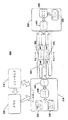
図1はプリント装置100のブロック図である。プリント装置100はワークピースコンベア105及び、プリントヘッドとも称される、プリンタハウジング110を備える。ワークピースコンベア105は一連のワークピース115,120,125,130,135,140,145とプリントヘッド110の間の相対運動を生じさせる。詳しくは、ワークピースコンベア105はプリントヘッド110の面150を横切る方向Dにワークピース115,120,125,130,135,140,145を搬送する。ワークピースコンベア105は、搬送中にワークピース115,120,125,130,135,140,145を保持できるローラー、ベルトまたはその他の素子を動かすステップモーターまたは連続回転モーターを備えることができる。ワークピース115,120,125,130,135,140,145は、その上に装置がプリントすることができる、数多くの様々な基板のいずれかとすることができる。例えば、ワークピース115,120,125,130,135,140,145は、紙、ボール紙、マイクロエレクトロニクスデバイスまたは食料品とすることができる。
FIG. 1 is a block diagram of the
プリントヘッド110はワークピース検出器155を収める。ワークピース検出器155は1つまたはそれより多くのワークピース115,120,125,130,135,140,145の位置を検出することができる。例えば、ワークピース検出器155は、面150の前面の一定の点を横切るワークピース115,120,125,130,135,140,145の縁端の通過を検出する、集成レーザ/光検出器とすることができる。
The
プリントヘッド110から離れた場所に制御エレクトロニクス160が配置される。制御エレクトロニクス160はケーブル195(例えば光ケーブル)及び最小限エレクトロニクス190によってプリントヘッド110とインターフェースする。制御エレクトロニクス160は装置100によるプリント作業の実施を制御する。制御エレクトロニクス160は一組の機械読取可能な命令の論理にしたがって作業を実施する1つまたはそれより多くのデータ処理デバイスを有することができる。制御エレクトロニクス160は、例えば、画像処理ソフトウエア及びプリントヘッド110におけるプリントを制御するためのシフトウエアを実行するパーソナルコンピュータ装置とすることができる。
制御エレクトロニクス160内にプリント画像バッファ165がおかれる。プリント画像バッファ165はプリント素子によるプリントのための画像データを格納する1つまたはそれより多くのデータ記憶デバイスである。例えば、プリント画像バッファ165はランダムアクセスメモリ(RAM)デバイスの集合体とすることができる。プリント画像バッファ165は、画像データを格納及び検索するために制御エレクトロニクス160がアクセスすることができる。
A
制御エレクトロニクス160はケーブル195及び最小限エレクトロニクス190を介してプリントヘッド110とインターフェースする。制御エレクトロニクス160はケーブル195を通じてデータを送ることができ、最小限エレクトロニクス190はプリントヘッド110におけるプリントのためにそのデータを受け取ることができる。制御エレクトロニクス160はプリントヘッド110に送るべきデータを生成するための特別の回路(例えば、図4を参照してさらに詳細に説明されるような、データポンプ)を有することができる。最小限エレクトロニクス190は、例えば、マイクロプロセッサ、トランシーバ及び最小限のメモリを有するフィールドプログラマブルゲートアレイ(FPGA)とすることができる。最小限エレクトロニクス190は、最小限エレクトロニクス190を切り離してプリントヘッド110及び/またはプリントヘッド110内のハードウエアを容易に変更できるように、プリントヘッド110に接続することができる。例えば、プリントヘッド110が新しいプリントモジュールを収める新しいプリントヘッドと交換される場合には、最小限エレクトロニクス190を古いプリントヘッド110から切り離して新しいプリントヘッドに接続することができる。
画像のプリントは、制御エレクトロニクス160が画像処理を実施し、プリントを制御し、最小限エレクトロニクス190がケーブル195を介して送られるデータを受取り、そのデータを用いてプリントヘッド110においてプリント素子を起動させるように、制御エレクトロニクス160と最小限エレクトロニクス190の間で分割される。したがって、例えば、画像データはジェットマップ画像データに変換することができ、これはジェットマップ画像データへの変換プロセスの一環として画像データを離散ユニット(例えば、以下でさらに詳細に説明される、画像バッファ)に分割する工程を含むことができる。遅延を画像データに挿入する(例えば、プリント素子連の展開に対応する遅延を挿入する)ことができる。制御エレクトロニクス160によって適切な時間に画像データを送る(例えば、画像データのデータパケットをエンコードしてトランシーバで送る)ことができ、一方、最小限エレクトロニクス190は画像データを受け取り(例えば、ケーブル195を通じて送られた画像データパケットをデコードし)、画像データがワークピース上にプリントされる(例えば、画像データにしたがってインクジェットノズルを起動させる)ように、画像データを渡すだけで済ませることができる。制御エレクトロニクス160はプリントヘッド110における画像のプリントを同期させることができる。先の例にしたがえば、制御エレクトロニクス160はワークピースの前縁の表示を受け取り、プリントヘッド110において画像をプリントさせるためにケーブル195を通じて画像データを送ることによって画像プリントを同期させることができる。
The image is printed by the
制御エレクトロニクス160は、ワークピースのワークピースコンベア105に沿う移動にしたがって、ワークピース上の「ジャストインタイム」画像プリントを可能にするような高データレートでプリントヘッド110に画像データを送ることができる。ジャストインタイムプリントの一実施形態において、プリントヘッド110への画像データ伝送は、パケット内の画像データをデータがプリントヘッド110に到着すると「実質的に即時に」プリントさせるトリガとしてはたらくことができる。本実施形態において、画像データは画像データのプリントに先立ちプリントヘッド上の記憶コンポーネントに格納されることはなく、データがプリントヘッドに到着するとプリントされ得る。ジャストインタイムプリントは画像データのプリントヘッド到着と実質的に即時の画像データプリントを指すこともある。
The
ジャストインタイムプリントの別の実施形態において、プリントヘッドで受け取られたデータは1つまたはそれより多くのラッチに格納され、プリントヘッドで受け取られている新しいデータまたは後続データがラッチされたデータをプリントするためのトリガとしてはたらくことができる。データ、後続データ及びラッチされたデータは、画像データパケットの形態で、プリントヘッドで受け取り、及び/または格納することができる。一事例において、プリントヘッドに到着する後続データは次順の後続データである。あるいは、プリントヘッドに到着する後続データは、次順の後続データの後に到着する後続データなどの、次順の後続データとは別の後続データである。画像データはそのような高データレートでプリントされているから、ラッチされたデータからプリントされるデータは、データがプリントヘッドに到着すると「実質的に即時に」プリントされると見ることもできる。 In another embodiment of just-in-time printing, data received at the printhead is stored in one or more latches, and new data or subsequent data received at the printhead is printed as latched data. It can act as a trigger to do. Data, subsequent data and latched data can be received and / or stored at the printhead in the form of image data packets. In one case, the subsequent data arriving at the print head is subsequent data in the next order. Alternatively, the subsequent data that arrives at the print head is subsequent data that is different from the subsequent data in the next order, such as subsequent data that arrives after the subsequent data in the next order. Since the image data is printed at such a high data rate, the data printed from the latched data can also be viewed as being "substantially immediately" printed when the data arrives at the printhead.
プリントヘッド110は最小限エレクトロニクス190及び小容量のメモリを有するから、プリントヘッド110は比較的低コストで実装することができる。プリントヘッド110上で用いられるメモリも低コストで実装できるタイプのメモリとすることができる。一実施形態において、プリントヘッド110上に実装されるメモリのタイプは、最小限エレクトロニクス190の一部とすることができるフィールドプログラマブルゲートアレイ(FPGA)集積回路(IC)の一部である。プリントヘッド110において画像データを高速でバッファする必要がほとんどまたは全くないから、プリントヘッド110を実装するためのコスト及び技術設計工数も低減できる。装置100は、例えば、それぞれが最小限エレクトロニクス190及び1本またはそれより多くのケーブルを用いる1つまたはそれより多くのデータポンプとのインターフェースを実装することができる、プリントヘッド110に複数のFPGAをもつ構成を含む、多くの構成においてプリントヘッド110への、広帯域で、同期し、ジャストインタイムの画像データのスケーラブル伝送を提供することができる。
Since the
図2及び3はプリントヘッド上のプリントモジュール及びプリント素子の構成を示す。詳しくは、図2はプリントヘッド110を側方から示し、図3はプリントヘッド110を下方から示す。プリントヘッド110は面150上にプリントモジュール205,210,215,220,225,230,305,310,315からなる集合体を有する。プリントモジュール205,210,215,220,225,230,305,310,315はそれぞれ1つまたはそれより多くのプリント素子を有する。例えば、プリントモジュール205,210,215,220,225,230,305,310,315はそれぞれ線形のインクジェットノズルアレイを有することができる。
2 and 3 show the configuration of the print module and the print element on the print head. Specifically, FIG. 2 shows the
この特定のプリントヘッド構成において、プリントモジュール205,305はコラム320に沿って並べて配置される。プリントモジュール210はコラム325に沿って配置される。プリントモジュール215,310はコラム330に沿って並べて配置される。プリントモジュール220はコラム335に沿って配置される。プリントモジュール225,315はコラム340に沿って並べて配置される。プリントモジュール230はコラム345に沿って配置される。コラム320,325,330,335,340,345に沿うこのプリントモジュール205,210,215,220,225,230,305,310,315の配置は面150上の有効プリント領域235をカバーする。有効プリント領域235は、プリントモジュール205,305のプリント素子からプリントモジュール230のプリント素子にわたる縦幅Wを有する。
In this particular printhead configuration,
プリントモジュール205,210,215,220,225,230,305,310,315は、画像の選択されたコンポーネントをプリントするためのプリント素子連に展開することができる。例えば、プリントモジュール205,210,305は面150の前面を移動していく基板の全横幅にわたって第1の色をプリントするための第1のプリント素子連に展開することができ、プリントモジュール215,220,310は全横幅にわたって第2の色をプリントするための第2のプリント素子連に展開することができ、プリントモジュール225,230,315は全横幅にわたって第3の色をプリントするための第3のプリント素子連に展開することができる。
別の例として、プリントモジュール205,210,215,220,225,230,305,310,315からなる群はモジュールの構成プリント素子のコラム位置に基づくプリント素子連に展開できる。例えば、第1のプリント素子連はそれぞれの構成プリント素子が単一コラムに配置されるように展開されたモジュール205,305を有することができる。第2のプリント素子連はプリントモジュール210だけを有することができる。モジュール215,310は第3の連を形成することができる。連4,5及び6はそれぞれ、モジュール220,225,モジュール315及びモジュール230を有する。このコラム態様でのプリント素子連形成により、画像データの複雑な実時間調整を必要とせずに、縦幅Wに対して、最終画像領域間に、無プリント領域が可変ではあるが小さいかまたは存在しない、連続する異種画像のプリントが可能になる。
As another example, a group of
別の例として、プリントモジュール205,210,215,220,225,230,305,310,315からなる群はモジュールの構成プリント素子の横位置に基づくプリント素子連に展開することができる。例えば、第1のプリント素子連は、それぞれの構成プリント素子が、モジュール215,220,310のプリント素子に対して、またモジュール225,230,315のプリント素子に対して、横方向の位置にシフトされるように展開された、モジュール205,210,305を有することができる。第2のプリント素子連は、それぞれの構成プリント素子が、モジュール205,210,305のプリント素子に対して、またモジュール225,230,315のプリント素子に対して、横方向の位置にシフトされるように展開された、モジュール215,220,310を有することができる。モジュール225,230,315は第3の連合を形成することができる。位置の相対シフトは、正味の効果として、プリントヘッド上のプリント素子間の横方向間隔を縮小し、よって画像をプリントすることができる解像度を実効的に高めるために、モジュールのプリント素子の横間隔より小さくすることができる。
As another example, the group of
それぞれのプリント素子連は、そのメモリ位置にいったん収められた画像データを連がプリントする、(図1に示される)プリント画像バッファ165内の専用メモリ位置を有することができる。例えば、プリント画像バッファ165が個々のバッファの待ち行列の集合体である場合、それぞれのプリント素子連はバッファの、個別の、専用待ち行列を有することができる。
Each print element series may have a dedicated memory location in the print image buffer 165 (shown in FIG. 1) where the series prints the image data once stored in that memory location. For example, if the
図4は一実施形態にしたがうプリント装置400の実装の略図を示す。装置400は、ワークピースコンベア405,プリントヘッド410,ワークピース検出器455及び制御エレクトロニクス460を備える。
FIG. 4 shows a schematic diagram of an implementation of a
ワークピースコンベア405はプリントヘッド410の有効プリント領域440の前面を方向Dにワークピース420,425,430,435を搬送する。ワークピースコンベア405はワークピース420,425,430,435の速度を検知するエンコーダ407を有する。エンコーダ407は検知した速度をエンコードする信号も発生し、その信号を制御エレクトロニクス460に渡す。ワークピース検出器455は、1つまたはそれより多くのワークピース420,425,430,435の位置を検出し、検出に基づいて(トリガ信号456及び457などの)トリガ信号を発生する、光センサである。
The
プリントヘッド410は一連のコラム411,412,413,414,415,416,417,418に沿って並べて配置されたプリントモジュールの集合体を有する。プリントモジュールのこの配置は有効プリント領域440をカバーする。コラム411,412,413,414,415,416,417,418のそれぞれに沿って展開されたそれぞれのプリントモジュール群はプリント素子連を構成する。例として、プリントモジュール491,493,495はコラム418に沿うプリント素子連を構成し、プリントモジュール492,494はコラム417に沿うプリント素子連を構成する。
The
制御エレクトロニクス460は装置400によるプリント作業の実施を制御する。制御エレクトロニクス460はプリント画像バッファの集合体465を有する。制御エレクトロニクス460は集合体465のプリント画像バッファにアクセスして画像データの格納及び検索を行うことができる。図4に示される構成において、集合体465には8つのプリント画像バッファがあり、それぞれのプリント画像バッファはコラム411,412,413,414,415,416,417,418の1つに沿って配置されたプリント素子連に専用である。例えば、プリント画像バッファ466,467,468,469はそれぞれ、コラム415,416,417,418に沿って配置されたそれぞれのプリント素子連に対応することができる。詳しくは、それぞれのプリント素子連は関係付けられているプリント画像バッファからの画像データしかプリントしない。
制御エレクトロニクス460はデータポンプ470も有する。「データポンプ」は、例えば、データを処理してプリントのために1つまたはそれより多くのプリントデバイスに送る、ハードウエア、ソフトウエア、プログラマブルロジックまたはこれらの組合せで実施される、機能コンポーネントを指す。一実施形態において、データポンプはダイレクトメモリアクセス(DMA)デバイスを指すことができる。データポンプ470はプリント素子連と、集合体465のそれぞれの専用プリント画像バッファの間のデータ通信路に沿って配置される。データポンプ470は集合体465のそれぞれのプリント画像バッファから画像データを検索し、格納することができる。データポンプ470は、集合体465のプリント画像バッファからプリント素子連への情報の通信に遅延をかけるための、制御エレクトロニクス460によるプログラムが可能である。
動作において、制御エレクトロニクス460は有効プリント領域440におけるプリント素子連の展開にしたがって画像データを分割することができる。制御エレクトロニクス460は分割された画像データを集合体465の適切なプリント画像バッファに割り当てることもできる。
In operation, the
ワークピース435がワークピースコンベア405で搬送されて有効プリント領域440に入ると、ワークピース検出器455がワークピース435の前縁を検出し、トリガ信号456を発生する。トリガ信号456の受信に基づいて、制御エレクトロニクス460はデータポンプ470を位置遅延471,472,473,474,475,476,477,478でプログラムすることができる。遅延471は集合体465の第1のプリント画像バッファからコラム411に沿って配置されたプリント素子連への画像データの通信を遅延させる。遅延472は集合体465の第2のプリント画像バッファからコラム412に沿って配置されたプリント素子連への画像データの通信を遅延させる。遅延473,474,475,476,477,478は集合体465のそれぞれのプリント画像バッファからコラム413,414,415,416,417,418に沿って配置されたそれぞれのプリント素子連への画像データの通信を遅延させる。
When the workpiece 435 is conveyed by the
ワークピース435がワークピースコンベア405で搬送されて有効プリント領域440の前面を通過していくと、コラム411,412,413,414,415,416,417,418に沿って配置されたプリント素子連が順次にプリントする。詳しくは、ワークピース435が有効プリント領域440の前面で一走査線を前進すると、データポンプ470が、コラム411,412,413,414,415,416,417,418に沿って配置されたプリント素子連における適切な受信器エレクトロニクスに画像データをダンプする(すなわちデータポンプ470はプリントデバイスへの画像データの送信を行わせる)。ダンプされた画像データは、有効プリント領域440におけるワークピース435のその時点での位置に対して起動されるべきプリント素子を識別する。プリント素子の識別は内在型、例えば、プリントデバイスにおけるプリント素子及び/またはプリント素子連の順序に対応するフォーマットにおける画像データパケット内の画像データの順序とすることができる。順次起動に対するデータは起動中に集合体465のプリント画像バッファからデータポンプ470にロードすることができる。
When the workpiece 435 is conveyed by the
ワークピース435がまだプリントされている間に、ワークピース430がワークピースコンベア405で搬送されて有効プリント領域440に入ることができる。ワークピース検出器455がワークピース430の前縁を検出し、トリガ信号457を発生する。トリガ信号457の受信に基づいて、制御エレクトロニクス460はデータポンプ470に遅延479,480,481,482,483,484,485,486を挿入させることができる。遅延479は集合体465の第1のプリント画像バッファからコラム411に沿って配置されたプリント素子連への画像データの通信を遅延させる。遅延480は集合体465の第2のプリント画像バッファからコラム412に沿って配置されたプリント素子連への画像データの通信を遅延させる。遅延481,482,483,484,485,486は集合体465のそれぞれのプリント画像バッファからコラム413,414,415,416,417,418に沿って配置されたプリント素子連のそれぞれへの画像データの通信を遅延させる。あるいは、遅延を既に画像データに挿入しておくことができ、トリガ信号がデータポンプ470に画像データを送信させることができる。
While the workpiece 435 is still being printed, the
ワークピース430がワークピースコンベア405で搬送されて有効プリント領域440に入ると、コラム411,412,413,414,415,416,417,418に沿って配置されたプリント素子連がワークピース430,435にプリントする。詳しくは、ワークピース435,430が一走査線を前進すると、データポンプ470がプリント素子に対する適切な受信器エレクトロニクスに画像データをダンプし、ワークピース435,430は同時にプリントされる。
When the
データ(例えばプリント走査線を定める画像データ)は、パケットベースプロトコルにしたがって、制御エレクトロニクス460とプリントヘッド410の間で送信することができる。図5はそのようなプロトコルにしたがってデータを送信するための装置500の概念図である。装置500は、メモリ505,データポンプ510,ソフトウエア515及びプリントデバイス520、例えば単プリントヘッドを備える。メモリ505,データダンプ510及びソフトウエア515は通常のパーソナルコンピュータ(PC)に収めることができる。メモリ505は、ペリフェラルコンポーネントインターコネクト(PCI)バス、PCI-X(拡張ペリフェラルコンポーネントインターコネクト)バス、PCIエクスプレスバスまたはその他の適するバスを介して利用できる、DMAアクセス可能なメモリとすることができる。メモリはデータポンプ510による処理のための画像データの格納に用いられる。
Data (eg, image data defining a print scan line) can be transmitted between the
ソフトウエア515は画像データの伝送を制御することができ、画像データをメモリ505に送ることができる。データポンプ510は画像データを用いて画像データパケットジェネレータ525において(「画像走査線パケット」とも称される)画像データパケットを生成することができる。画像データパケットの生成には、画像データパケットジェネレータ525における画像データパケットのシリアル化を含めることができる。メモリ505への画像データの送信に加えて、ソフトウエア515は制御データをデータポンプ510に送ることができる。制御データはプリントデバイス520を制御するために用いることができるいずれかのタイプのデータを含むことができる。制御データパケットは制御データパケットジェネレータ545において制御データから生成することができる。
画像データパケット565などの、画像データパケットは、フレーム開始、データセクション及びフレーム終端を含むことができる。データセクションはプリントのためにプリントデバイスにおいて用いることができる画像データを含む。画像データパケットのためのフレームフォーマットを定めるプロトコルが、画像データパケットは画像データの1本またはそれより多くの走査線並びに一定のフレーム開始及びフレーム終端を含むべきであると定めることができる。例えば、プロトコルは32ビットのフレーム開始、1本またはそれより多くの走査線を表すデータセクションとして3,552ビットのビットマップ画像データ及び32ビットのフレーム終端を含むように画像データパケットを定めることができる。
An image data packet, such as
画像データパケットの走査線の各部分はプリントデバイスにおけるプリント素子連に対応することができる。例として、プリントデバイスが8つのプリント素子連を有していれば、そのプリントデバイス用にフレームが形成された画像データパケットは一走査線につき、それぞれのプリント素子連に対して1つの部分の、8つの部分を表す画像データを有することがでよう。画像データパケットは単一の画像からのデータを含むように制限される必要はない。例えば、プロトコルは画像データパケットがそれぞれのプリント素子連に対する画像データ部分を含むべきであり、その場合、それぞれの部分はプリント素子連に1回プリントさせる(例えば、プリント素子がインクジェットプリントノズルの場合、これは、単刷とも称される、インクジェットノズルの単起動であろう)に十分であると定めることができる。装置が8つのプリント素子連をもつこの例においては、画像データの第1の4つの部分が第1の画像に対応し、画像データの第2の4つの部分が第2の画像に対応していれば、画像データパケットは2つの画像からの画像データ部分を含むことができる。単一の画像データパケットが2つの異なる画像からの画像データを含むことができれば、画像データパケットにより2つの異なるワークピース上に(類似しているかまたは同様の)2つの画像のプリントが可能になる点で有利となり得る。同様に、画像データパケットはいくつかの異なる画像からの画像情報を含むことができ、対応するプリント素子連によるこれらの画像の同時プリントが可能になる。別の実施形態において、画像データパケットが1本またはそれより多くの走査線を表す必要はなく、むしろ、プリント素子連に対応する画像データの別の分割(すなわち部分)を含むように画像データパケットを定めることができる。例えば、それぞれのプリント素子連が一定の色をプリントする場合には、画像データの各部分が異なるプリント素子連によってプリントされることが必要な異なる色に対応することができるように、画像データを分割し、画像データパケットに含めることができる。 Each portion of the scan line of the image data packet can correspond to a printing element sequence in the printing device. As an example, if a printing device has eight printing element series, an image data packet in which a frame is formed for that printing device is one part for each printing element series per scan line. It would be possible to have image data representing 8 parts. The image data packet need not be limited to contain data from a single image. For example, the protocol should include an image data packet for each print element series, in which case each part is printed once by the print element series (e.g., if the print element is an inkjet print nozzle, This may be sufficient to be a single activation of the inkjet nozzle, also referred to as a single press). In this example where the device has eight print element series, the first four portions of the image data correspond to the first image and the second four portions of the image data correspond to the second image. Thus, the image data packet can include image data portions from two images. If a single image data packet can contain image data from two different images, the image data packet allows the printing of two images (similar or similar) on two different workpieces. Can be advantageous in terms. Similarly, an image data packet can contain image information from several different images, allowing simultaneous printing of these images by a corresponding series of print elements. In another embodiment, the image data packet need not represent one or more scan lines, but rather includes another division (ie, a portion) of the image data corresponding to the print element series. Can be determined. For example, if each print element series prints a certain color, the image data is stored so that each part of the image data can correspond to a different color that needs to be printed by a different print element series. It can be divided and included in the image data packet.
制御データパケット570などの制御データパケットは、フレーム開始、データセクション及びフレーム終端を含むことができる。データセクションは制御情報を表す。例えば、データセクションは図のデータポンプ側からプリンタ側へのコマンドまたは図のプリンタ側からデータポンプ側へのステータス情報を含むことができる。コマンドは、プリントモジュールの温度についてのクエリー、プリントモジュールの温度を上げるかまたは下げるためのコマンド、プリント素子の間隔を変えるためのコマンド等を含むことができる。ステータス情報は、例えば、プリントモジュール温度、プリント素子間隔、プリント素子数等を含むことができる。
A control data packet, such as
データパケットの送信及び受信は論理的に2つのデータチャネルを含むことができ、第1のデータチャネルはデータポンプ510からプリントデバイス520への一方向性画像データチャネルであり、第2のデータチャネルは双方向性制御データチャネルである。データパケットは、画像データが送られていないときにデータダンプ510からプリントデバイス520に制御データパケットが送られるように、インターリーブすることができる。例えば、画像データパケットの送信と干渉せずに制御データパケットの送信をサポートするに十分な帯域幅がある場合、画像データパケットの直後に制御データパケットを送ることができる。別の例として、画像のプリントにおける一定の時間を、例えば画像またはプリントジョブ間の、制御データパケットの送信に用いられる時間とすることができる。双方向シリアル通信には送信回線及び受信回線が含まれ得るから、制御データパケットをプリントデバイス520からデータポンプ510に送り、同時に画像データパケットをプリントデバイス520に送ることができる。データ送信のための2つの論理チャネルの定義及びこれらのチャネルの様々な態様は、データ送信のための、先に説明したプロトコルの1つに含めることができる。
The transmission and reception of data packets can logically include two data channels, the first data channel is a unidirectional image data channel from the data pump 510 to the
画像データパケット及び制御データパケットはエンコーダ/デコーダ530でエンコードされる。エンコーダ/デコーダ530は8B/10Bエンコード方式にしたがってデータをエンコードすることができる。エンコードされた画像データパケットはトランシーバ535で送信される。トランシーバ535はプリントデバイス520に接続された送信回線540を通じて画像データパケットを送受するように作用することができる。
The image data packet and the control data packet are encoded by the encoder /
プリントデバイス520において、FPGAに実装された制御エレクトロニクスなどの、制御エレクトロニクスがトランシーバ550における画像データパケットの送信及び/または受信のために作用することができる。画像データパケットは、8B/10Bエンコード方式にしたがってエンコーダ/デコーダ530でエンコード及び/またはデコードすることができる。別の実施形態において、物理的通信インターフェースを通してDCバランスを確実にとるために8B/10Bエンコード以外の技法を用いることができる。いくつかの別の実施形態は(短距離伝送では特に)伝送媒体にDCバランスを必要とせず、非バランス型エンコード手法を用いることができる。制御パケットは制御パケットジェネレータ560で生成することができる。これらの制御パケットは、例えば、プリントモジュール温度などの、ステータス情報を含むことができる。制御パケットはデータポンプ側から送られた制御パケットに応答してプリンタ側で生成することができる。
At
単プリントヘッドは複数のプリントモジュールを有することができ、プリントモジュールのそれぞれは相異なるプロパティを有することができる。これらのプロパティには、例えば、プリントモジュールのインクジェットノズル数、ノズル間隔並びにノズル及び/またはモジュールの方位を含めることができる。さらに、1つのプリント装置のプリントヘッドは、顧客の最終用途(例えば、新聞印刷または食品、例えばキャンディへの印刷)に基づいて、別の装置のプリントヘッドと異なることができる。これらの差異を補整するため、プリント装置を制御するソフトウエアは、特定のプリントヘッド構成に適合させる必要がある。 A single printhead can have multiple print modules, and each of the print modules can have different properties. These properties can include, for example, the number of inkjet nozzles in the print module, nozzle spacing, and nozzle and / or module orientation. Furthermore, the print head of one printing device can differ from the print head of another device based on the customer's end use (eg, newspaper printing or food, eg, printing on candy). In order to compensate for these differences, the software that controls the printing device needs to be adapted to the particular printhead configuration.
一実施形態において、制御エレクトロニクス160の制御ソフトウエアはプリント装置の(1つまたは複数の)プリントヘッドのプロパティを検出することができる。例えば、制御ソフトウエアはプリントヘッドに問い合せてその構成を判定するために制御通信チャネルを用いることができる。この情報は次いで、特定のプリントヘッド構成に合せるためにソフトウエアを構成するための手作業コーディングを必要とせずに、自動的に画像データパケットを生成するために用いることができる。
In one embodiment, the control software of the
図6A及び6Bには一実施形態にしたがう画像データパケット生成プロセスを説明するフローチャートがある。プリント装置は複数のプリントヘッドを有することができ、プリントヘッドのそれぞれは、異なる、プリントモジュールの数、構成及び/またはタイプを有することができる。制御ソフトウエアは、ステップ602において、プリント装置の起動中またはプリント装置の新しい(1つまたは複数の)プリントヘッドの装着中に、プリントヘッドにクエリーを送ることができる。クエリーは制御パケットに入れて通信チャネルを通じて送ることができる。
6A and 6B are flowcharts illustrating an image data packet generation process according to one embodiment. A printing device can have multiple printheads, each of which can have a different number, configuration and / or type of print modules. The control software may send a query to the print head at
プリントヘッドは制御ソフトウエアに制御パケットを送ることで回答することができる。制御パケットは、プリントヘッドのメモリ(例えばROMまたはフラッシュメモリ)に格納されたプリントヘッドのプロパティに対応する情報を含むことができる。情報は、プリントモジュールの寸法、量及びプリントヘッド内のレイアウトなどの、プリントヘッドの物理的属性を含む固有の構成情報とすることができる。定義は、プリントヘッドのプリント素子及び/またはプリントモジュールの順序、プリント素子及び/またはプリントモジュールの間隔、及びプリントヘッドの本来の解像度を識別することもできる。 The printhead can respond by sending a control packet to the control software. The control packet may include information corresponding to the printhead properties stored in the printhead memory (eg, ROM or flash memory). The information may be specific configuration information including physical attributes of the print head, such as the print module dimensions, quantity, and layout within the print head. The definition may also identify the order of the printhead print elements and / or print modules, the print element and / or print module spacing, and the printhead's native resolution.
あるいは、プリントヘッドのプロパティに対応する情報は、制御センタにおいて既知の情報、例えば、制御ソフトウエアに格納されたテーブルの構成情報収録項目、に対応するパーツ番号または構成タイプ表示子などの、より一般的な情報とすることができる。 Alternatively, the information corresponding to the properties of the printhead is more general, such as part number or configuration type indicator corresponding to information known in the control center, for example, configuration information recording items of the table stored in the control software. Information.
制御ソフトウエアはステップ604で回答制御パケットを受け取り、ステップ606で、パケット内の情報を用いて、例えばテーブルルックアップを行うことにより、プリントヘッド構成を識別する。制御ソフトウエアはステップ608で構成情報を格納することができる。この格納された情報は、たとえば起動またはリセット状態に応答して更新することができる。
The control software receives the reply control packet at step 604 and identifies the printhead configuration at step 606 using information in the packet, for example, by performing a table lookup. The control software can store the configuration information at
個々のプリントヘッドからの情報は一水準の構成情報を与え、最終書換水準として用いられる。より高水準の構成情報は別のソースから得ることができる。例えば、複数のプリントヘッドをもつ装置において、複数のプリントヘッドの内の1つまたはそれより多くは同じデータポンプに関連付けられ、複数のプリントヘッドの物理的関係を識別する装置レベル構成情報をアプリケーションが提供することができる。アプリケーションは、プリント解像度、グレイスケール(すなわち、それぞれのピクセルで用いられるビット数)、プリント方向(例えば、プリントヘッドの横方向走査)及び(例えば、集成プリントヘッドが180°回転されるならば)ヘッド方位などの、プリントのための動的パラメータを含む構成情報も提供することもできる。 Information from individual printheads provides a level of configuration information and is used as the final rewrite level. Higher levels of configuration information can be obtained from other sources. For example, in a device with multiple printheads, one or more of the multiple printheads may be associated with the same data pump and the application may provide device level configuration information that identifies the physical relationship of the multiple printheads. Can be provided. Applications include print resolution, gray scale (ie, the number of bits used in each pixel), print direction (eg, lateral scan of the print head) and head (eg, if the integrated print head is rotated 180 °) Configuration information including dynamic parameters for printing, such as orientation, can also be provided.
特定のプリントヘッド構成に適切な画像データパケットを生成するために、制御ソフトウエアはステップ610で構成情報を用いて画像データパケット生成を担当するコンポーネント、例えば、図5のソフトウエア515,画像データパケットジェネレータ525及びエンコーダ/デコーダ530を設定する。すなわち、制御ソフトウエアは、プリントヘッドのプリント素子に所望の画像の走査線の対応する部分を忠実にプリントさせるであろう画像データパケットを生成するように画像データ生成コンポーネントを構成する。構成作業には、ステップ612における、プリントヘッドのプリント素子及びプリントモジュールの特定のレイアウトに適切なプリント素子連を定める作業を含めることができる。ソフトウエアは次いで、ステップ614でプリント素子連に基づいて画像を分割し、ステップ616でプリント素子連に基づいて画像待ち行列を生成する。
In order to generate an image data packet appropriate for a particular printhead configuration, the control software uses the configuration information at step 610 to identify the component responsible for generating the image data packet, such as
画像の分割及び画像待ち行列の生成には、プリント素子連のそれぞれのプリントモジュールに対する画像データのバッファの生成、同じプリント素子連に関連付けられたバッファの結合、及び画像待ち行列に関連付けられた結合バッファを含む画像待ち行列の生成を含めることができる。例えば、図4においては、プリントヘッドに20のプリントモジュールがある。それぞれのバッファがプリントモジュールに対応する画像データを有するように画像を分割することができる。次いで、コラム418のプリントモジュールを含むプリント素子連のプリントモジュール491,493,495などの、同じプリント素子連のプリントモジュールに対応するバッファを結合し、よって結合されたバッファ(例えば、コラム418に沿うプリント素子の全てに関連付けられたバッファ)をプリント素子連に関連付けることができる。次いで、同じプリント素子に関連付けられた結合バッファを、画像待ち行列が生成され、それぞれの画像待ち行列が同じプリント素子連に対応する結合バッファを有するように、画像待ち行列に入れることができる。 Image segmentation and image queue generation include generating image data buffers for each print module in a print element series, combining buffers associated with the same print element series, and combining buffers associated with image queues. The generation of an image queue containing can be included. For example, in FIG. 4, there are 20 print modules in the print head. The image can be divided so that each buffer has image data corresponding to the print module. A buffer corresponding to the same print element series print module, such as a print element series print module 491,493,495 including the print module of column 418, is then combined, and thus the combined buffer (eg, along column 418). A buffer associated with all of the print elements) can be associated with the print element series. The combined buffers associated with the same print element can then be placed in the image queue such that an image queue is generated and each image queue has a combined buffer corresponding to the same series of print elements.
ソフトウエアはテーブル駆動型手法を用いて、画像を分割して画像待ち行列を満たすことができる。ソフトウエアは構成情報を用いてテーブルを生成することができる。テーブルには、プリントヘッドのプリント素子のレイアウトにしたがってデータを抽出するときに用いることができるビットパターン及びシフトパターンを含めることができる。次いで、一組の画像データのバッファを生成するために汎用処理ルーチンをテーブルとともに用いることができ、それぞれのバッファはプリントヘッドのプリント素子連に対応する。処理ルーチンは見いだされた情報及び処理を実行するためにアプリケーションから受け取ったより高水準の構成情報のいずれも用いる。次いで、同じプリント素子連に対応する画像データバッファが同じ画像待ち行列に入るように、画像待ち行列をプリント素子連に対応する画像データバッファで満たすことができる(例えば、第1のプリント素子連に対応する全てのバッファが第1の画像待ち行列にあり、第2のプリント素子連に対応する全てのバッファが第2の画像待ち行列にあり、以下同様とすることができる)。画像待ち行列は、画像バイトを並列操作することができる、並列処理によって効率的に満たすことができる。テーブル駆動型手法を用いることにより製品ファミリーを含む様々なタイプのプリントヘッドにかけて、高度に最適化された待ち行列生成ルーチン(例えば、上述した汎用ルーチンを含むルーチン)を、最適化されたルーチンをほとんどまたは全く改変せずに、用いることができる。 Software can use table-driven techniques to divide the image and fill the image queue. The software can generate a table using the configuration information. The table can include bit patterns and shift patterns that can be used when extracting data according to the print element layout of the printhead. A general purpose processing routine can then be used with the table to generate a set of image data buffers, each buffer corresponding to a print element series of the printhead. The processing routine uses both the information found and the higher level configuration information received from the application to perform the processing. The image queue can then be filled with image data buffers corresponding to the print element series such that the image data buffers corresponding to the same print element series enter the same image queue (eg, the first print element series). All corresponding buffers are in the first image queue, all buffers corresponding to the second print element series are in the second image queue, and so on). The image queue can be efficiently filled by parallel processing, which can manipulate image bytes in parallel. Using table-driven techniques, many types of printheads, including product families, can use highly optimized queuing routines (eg, routines including the generic routines described above) and most optimized routines. Or it can be used without any modification.
ソフトウエアで生成された画像バッファをデータポンプがメモリから検索することができ、ステップ618で画像データパケットを生成するために画像データパケットジェネレータが検索された画像バッファを用いることができる。次いでステップ620で画像データパケットがエンコードされ、プリントヘッドに送信される。
The software generated image buffer can be retrieved from memory by the data pump, and the image buffer retrieved by the image data packet generator can be used to generate an image data packet in
上述したように、制御ソフトウエアに格納された構成情報は起動またはリセット状態に応答して更新することができる。制御ソフトウエアはそのような状態の発生に応答して接続された(1つまたは複数の)プリントヘッドにクエリーを送ることができ、何らかの変更がなされていれば、構成情報を更新する。これにより、プリント装置の個々のプリントヘッドのアップグレードまたは交換が容易になり、プリント装置間の制御ソフトの移植性が高められる。 As described above, the configuration information stored in the control software can be updated in response to a startup or reset state. The control software can send a query to the connected print head (s) in response to the occurrence of such a condition and updates the configuration information if any changes have been made. This facilitates upgrade or replacement of individual print heads of the printing apparatus, and improves portability of control software between the printing apparatuses.
本明細書に開示された主題及び説明された機能動作の全てはデジタルエレクトロニクス回路で、あるいは、本明細書に開示された構造的手段及びその構造的等価物またはこれらの組合せを含む、コンピュータソフトウエア、ファームウエアまたはハードウエアで実施することができる。開示された主題は、データ処理装置、例えば、プログラマブルプロセッサ、単体コンピュータまたは複合コンピュータによる実行のため、またはこれらの動作を制御するための、1つまたはそれより多くのコンピュータプログラム製品に、すなわち情報記憶媒体、例えば機械読出可能記憶装置または伝搬信号に、実態的に具現化された1つまたはそれより多くのコンピュータプログラムとして実施することができる。(プログラム、ソフトウエア、ソフトウエアアプリケーションまたはコードとしても知られる)コンピュータプログラムは、コンパイラ言語またはインタプリータ言語を含む、いずれかの形態のプログラミング言語で書くことができ、スタンドアローンプログラムとしての形態あるいはモジュール、サブルーチン、またはコンピュータ環境における使用に適するその他のユニットとしての形態を含む、いずれかの形態で展開することができる。 All of the subject matter disclosed herein and the described functional operations are digital software circuits, or computer software comprising structural means disclosed herein and structural equivalents thereof or combinations thereof Can be implemented in firmware or hardware. The disclosed subject matter relates to one or more computer program products, i.e., information storage, for execution by a data processing device, e.g., a programmable processor, a single computer or a complex computer, or for controlling these operations. It can be implemented as one or more computer programs that are practically embodied on a medium, such as a machine-readable storage device or a propagated signal. A computer program (also known as a program, software, software application or code) can be written in any form of programming language, including a compiler language or an interpreter language, in the form or module as a stand-alone program, It can be deployed in any form, including as a subroutine or other unit suitable for use in a computer environment.
開示された主題の方法工程を含む、本明細書に説明されたプロセスフロー及び論理フローは、入力データの処理及び出力の生成により開示された主題の機能を実施するために1つまたはそれより多くのコンピュータプログラムを実行する1つまたはそれより多くのプログラマブルプロセッサによって実施することができる。プロセスフロー及び論理フローは、専用目的論理回路、例えば、FPGAまたはASIC(特定目的集積回路)により実施することができ、開示された主題の装置は専用目的論理回路、例えば、FPGAまたはASIC(特定目的集積回路)として実施することができる。 The process flows and logic flows described herein, including method steps of the disclosed subject matter, can include one or more to perform the disclosed subject matter functions by processing input data and generating output. Can be implemented by one or more programmable processors executing a computer program. Process flows and logic flows can be implemented by dedicated purpose logic circuits, such as FPGAs or ASICs (special purpose integrated circuits), and the disclosed subject matter can be implemented by dedicated purpose logic circuits, such as FPGAs or ASICs (special purpose integrated circuits). Integrated circuit).
多くの実施形態を説明した。それにもかかわらず、様々な改変がなされ得ることは当然であろう。例えば、図6A及び6Bのフローチャートを参照して説明されたプロセスは、ある数の、ある種類のプロセスからなるが、別の実施形態は追加の及び/または異なるプロセスを含むことができる。したがって、他の実施形態も添付される特許請求の範囲内にある。 A number of embodiments have been described. Nevertheless, it will be appreciated that various modifications can be made. For example, the process described with reference to the flowcharts of FIGS. 6A and 6B consists of a certain number of types of processes, but other embodiments can include additional and / or different processes. Accordingly, other embodiments are within the scope of the appended claims.
100 プリント装置
105 ワークピースコンベア
110 プリントヘッド
115,120,125,130,135,140,145 ワークピース
150 プリントヘッド面
155 ワークピース検出器
160 制御エレクトロニクス
165 プリント画像バッファ
190 最小限エレクトロニクス
195 ケーブル
205,210,215,220,225,230,305,310,315 プリントモジュール
235 有効プリント領域
DESCRIPTION OF
Claims (27)
プリントデバイスのプロパティに対応する情報についてのリクエストを前記プリントデバイスに送る工程、
前記プリントデバイスのプロパティに対応する情報を前記プリントデバイスから受け取る工程、
前記受け取った情報に基づいて前記プリントデバイスの構成パラメータを識別する工程、
前記構成パラメータに基づいて画像を部分画像に分割する工程、
それぞれが1つまたはそれより多くの部分画像を含む複数の画像データパケットを生成する工程、及び
前記画像データパケットを前記プリントデバイスに送る工程、
を含むことを特徴とする方法。 In a computer-implemented method,
Sending a request for information corresponding to properties of the printing device to the printing device;
Receiving from the printing device information corresponding to properties of the printing device;
Identifying configuration parameters of the print device based on the received information;
Dividing the image into partial images based on the configuration parameters;
Generating a plurality of image data packets each containing one or more partial images; and sending the image data packets to the printing device;
A method comprising the steps of:
前記プリントデバイスのプロパティに対応する情報を受け取る前記工程が、前記制御データチャネルを通じて第2の制御データパケットを受け取る工程を含むことを特徴とする請求項1に記載の方法。 Sending the request comprises sending a first control data packet over a control data channel;
The method of claim 1, wherein the step of receiving information corresponding to a property of the printing device includes receiving a second control data packet over the control data channel.
構成パラメータを識別する前記工程が前記識別子に基づいてテーブル内の構成パラメータを識別する工程を含むことを特徴とする請求項1に記載の方法。 The information corresponding to the property of the printhead includes an identifier assigned to the printhead;
The method of claim 1, wherein identifying the configuration parameter comprises identifying a configuration parameter in a table based on the identifier.
画像を分割する前記工程が、前記テーブルを用いて前記画像を分割する工程を含むことを特徴とする請求項1に記載の方法。 Further comprising generating a table based on the configuration parameters;
The method of claim 1, wherein the step of dividing an image includes the step of dividing the image using the table.
をさらに含み、
分割する前記工程が前記プリント素子連に基づいて前記画像を部分画像に分割する工程を含む、
ことを特徴とする請求項1に記載の方法。 Using the configuration parameters to generate a print element string;
Further including
The step of dividing includes dividing the image into partial images based on the print element sequence;
The method according to claim 1.
をさらに含み、
画像を分割する前記工程が、前記構成パラメータに基づいて前記画像を部分画像に分割する工程を含むことを特徴とする請求項1に記載の方法。 Receiving information corresponding to a relationship between the print head and one or more print heads;
Further including
The method of claim 1, wherein the step of dividing an image includes the step of dividing the image into partial images based on the configuration parameters.
プリントデバイスのプロパティに対応する情報についてのリクエストを前記プリントデバイスに向けて送らせる、
前記プリントデバイスのプロパティに対応する情報を前記プリントデバイスから受け取らせる、
前記受け取った情報に基づいて前記プリントデバイスの構成パラメータを識別させる、
前記構成情報に基づいて画像を部分画像に分割させる、
それぞれが1つまたはそれより多くの部分画像を含む複数の画像データパケットを生成させる、及び
前記画像データパケットを前記プリントデバイスに向けて送らせる、
ために使用できることを特徴とする製品。 In a computer program product that is actually embodied in an information storage medium,
Sending a request for information corresponding to the properties of the printing device to the printing device;
Receiving information corresponding to properties of the printing device from the printing device;
Identifying configuration parameters of the print device based on the received information;
Dividing the image into partial images based on the configuration information;
Generating a plurality of image data packets, each including one or more partial images, and sending the image data packets toward the printing device;
Products that can be used for.
前記装置に前記プリントデバイスのプロパティに対応する情報を受け取らせるために作用する命令が前記装置に前記制御データチャネルを通じて第2の制御データパケットを受け取らせるために作用する命令を含む、
ことを特徴とする請求項10に記載の製品。 Instructions that act to cause the device to send a request include instructions that act to cause the device to send a first control data packet over a control data channel;
Instructions that act to cause the apparatus to receive information corresponding to properties of the printing device include instructions that act to cause the apparatus to receive a second control data packet over the control data channel;
The product of claim 10.
前記装置に構成パラメータを識別させるために作用する命令が前記装置に前記識別子に基づいてテーブル内の構成パラメータを識別させるために作用する命令を含む、
ことを特徴とする請求項10に記載の製品。 The information corresponding to the property of the printhead includes an identifier assigned to the printhead;
Instructions that act to cause the device to identify configuration parameters include instructions that act to cause the device to identify configuration parameters in a table based on the identifier;
The product of claim 10.
前記装置に画像を分割させるために作用する命令が、前記装置に前記テーブルを用いて前記画像を分割させるために作用する命令を含むことを特徴とする請求項10に記載の製品。 Further comprising instructions for causing the apparatus to generate a table based on the configuration parameters;
11. The product of claim 10, wherein the instructions that operate to cause the device to split an image include instructions that operate to cause the device to split the image using the table.
前記装置に分割させるために作用する命令が前記装置に前記プリント素子連に基づいて前記画像を部分画像に分割させるために作用する命令を含む、
ことを特徴とする請求項10に記載の製品。 Further comprising instructions for causing the apparatus to generate a print element string using the configuration parameters;
Instructions that act to cause the device to divide include instructions that act to cause the device to divide the image into partial images based on the print element sequence;
The product of claim 10.
前記装置に画像を分割させるために作用する命令が前記装置に前記構成パラメータに基づいて前記画像を部分画像に分割させるために作用する命令を含む、
ことを特徴とする請求項10に記載の製品。 Further comprising instructions that operate to cause the apparatus to receive information corresponding to a relationship between the print head and one or more print heads;
Instructions that act to cause the device to divide the image include instructions that act to cause the device to divide the image into partial images based on the configuration parameters;
The product of claim 10.
プリントデバイスのプロパティに対応する情報についてのリクエストを前記プリントデバイスに送るための手段、
前記プリントデバイスのプロパティに対応する情報を前記プリントデバイスから受け取るための手段、
前記受け取った情報に基づいて前記プリントデバイスの構成パラメータを識別するための手段、
前記構成パラメータに基づいて画像を部分画像に分割するための手段、
それぞれが1つまたはそれより多くの部分画像を含む複数の画像データパケットを生成するための手段、及び
前記画像データパケットを前記プリントデバイスに送るための手段、
を備えることを特徴とする装置。 In the printing device,
Means for sending a request for information corresponding to properties of the printing device to said printing device;
Means for receiving information from the printing device corresponding to properties of the printing device;
Means for identifying a configuration parameter of the printing device based on the received information;
Means for dividing the image into partial images based on the configuration parameters;
Means for generating a plurality of image data packets each including one or more partial images; and means for sending the image data packets to the printing device;
A device comprising:
制御データチャネルを通じて第2の制御データパケットを受け取るための手段をさらに含むことを特徴とする請求項19に記載の装置。 Said means for sending a request comprises means for sending a first control data packet over a control data channel;
The apparatus of claim 19, further comprising means for receiving a second control data packet over a control data channel.
をさらに含むことを特徴とする請求項19に記載の装置。 Means for sending the image data packet over an image data channel;
20. The apparatus of claim 19, further comprising:
前記識別子に基づいてテーブル内の構成パラメータを識別するための手段をさらに含むことを特徴とする請求項19に記載の装置。 The information corresponding to the property of the printhead includes an identifier assigned to the printhead;
The apparatus of claim 19, further comprising means for identifying a configuration parameter in a table based on the identifier.
をさらに含み、
画像の前記分割が前記テーブルを用いる前記画像の分割を含む、
ことを特徴とする請求項19に記載の装置。 Means for generating a table based on the configuration parameters;
Further including
The segmentation of the image includes segmentation of the image using the table;
The apparatus of claim 19.
前記プリント素子連に基づいて前記画像を分割するための手段、
をさらに含むことを特徴とする請求項19に記載の装置。 Means for using the configuration parameter to generate a print element series; and means for segmenting the image based on the print element series;
20. The apparatus of claim 19, further comprising:
前記構成パラメータに基づいて前記画像を部分画像に分割するための手段、
をさらに含むことを特徴とする請求項19に記載の装置。 Means for receiving information corresponding to a relationship between the print head and one or more print heads; and means for dividing the image into partial images based on the configuration parameters;
20. The apparatus of claim 19, further comprising:
Applications Claiming Priority (2)
| Application Number | Priority Date | Filing Date | Title |
|---|---|---|---|
| US10/977,298 US8199342B2 (en) | 2004-10-29 | 2004-10-29 | Tailoring image data packets to properties of print heads |
| PCT/US2005/036807 WO2006049836A2 (en) | 2004-10-29 | 2005-10-11 | Tailoring image data packets to properties of print heads |
Publications (2)
| Publication Number | Publication Date |
|---|---|
| JP2008517811A true JP2008517811A (en) | 2008-05-29 |
| JP2008517811A5 JP2008517811A5 (en) | 2008-12-04 |
Family
ID=35708633
Family Applications (1)
| Application Number | Title | Priority Date | Filing Date |
|---|---|---|---|
| JP2007538968A Pending JP2008517811A (en) | 2004-10-29 | 2005-10-11 | Adapting image data packets to printhead properties |
Country Status (6)
| Country | Link |
|---|---|
| US (1) | US8199342B2 (en) |
| EP (1) | EP1805593A2 (en) |
| JP (1) | JP2008517811A (en) |
| KR (1) | KR101187389B1 (en) |
| CN (1) | CN100483327C (en) |
| WO (1) | WO2006049836A2 (en) |
Cited By (7)
| Publication number | Priority date | Publication date | Assignee | Title |
|---|---|---|---|---|
| US7722147B2 (en) | 2004-10-15 | 2010-05-25 | Fujifilm Dimatix, Inc. | Printing system architecture |
| US7907298B2 (en) | 2004-10-15 | 2011-03-15 | Fujifilm Dimatix, Inc. | Data pump for printing |
| US7911625B2 (en) | 2004-10-15 | 2011-03-22 | Fujifilm Dimatrix, Inc. | Printing system software architecture |
| US8068245B2 (en) | 2004-10-15 | 2011-11-29 | Fujifilm Dimatix, Inc. | Printing device communication protocol |
| US8085428B2 (en) | 2004-10-15 | 2011-12-27 | Fujifilm Dimatix, Inc. | Print systems and techniques |
| US8199342B2 (en) | 2004-10-29 | 2012-06-12 | Fujifilm Dimatix, Inc. | Tailoring image data packets to properties of print heads |
| US8251471B2 (en) | 2003-08-18 | 2012-08-28 | Fujifilm Dimatix, Inc. | Individual jet voltage trimming circuitry |
Families Citing this family (15)
| Publication number | Priority date | Publication date | Assignee | Title |
|---|---|---|---|---|
| US7556327B2 (en) * | 2004-11-05 | 2009-07-07 | Fujifilm Dimatix, Inc. | Charge leakage prevention for inkjet printing |
| JP5485987B2 (en) | 2008-06-06 | 2014-05-07 | フジフィルム ディマティックス, インコーポレイテッド | Object detection for printing |
| US8395798B2 (en) | 2010-07-15 | 2013-03-12 | Fujifilm Dimatix, Inc. | Printing objects using a rolling buffer |
| WO2013001366A1 (en) * | 2011-06-29 | 2013-01-03 | Markem-Imaje | Universal printing controller |
| CN103182864B (en) * | 2011-12-31 | 2015-05-20 | 北大方正集团有限公司 | Digital printing synchronous control device and control method |
| WO2013124737A2 (en) * | 2012-02-21 | 2013-08-29 | Markem-Imaje | A field programmable gate array and corresponding method for dynamic print technologies |
| EP3212405B1 (en) * | 2014-10-29 | 2021-12-01 | Hewlett-Packard Development Company, L.P. | Printhead fire signal control |
| WO2017058125A2 (en) * | 2015-09-28 | 2017-04-06 | Ali Turan | Data transfer and use method in inkjet printheads |
| US9925804B2 (en) * | 2016-01-29 | 2018-03-27 | Electronics For Imaging, Inc. | Printing independent images by sharing printer heads |
| US11407218B2 (en) | 2019-02-06 | 2022-08-09 | Hewlett-Packard Development Company, L.P. | Identifying random bits in control data packets |
| EP3921168A4 (en) | 2019-02-06 | 2022-11-30 | Hewlett-Packard Development Company, L.P. | Data packets comprising random numbers for controlling fluid dispensing devices |
| BR112021014394A2 (en) | 2019-02-06 | 2021-09-21 | Hewlett-Packard Development Company, L.P. | INTEGRATED CIRCUITS INCLUDING CUSTOMIZATION BITS |
| JP7146102B2 (en) | 2019-02-06 | 2022-10-03 | ヒューレット-パッカード デベロップメント カンパニー エル.ピー. | Printed component with memory array using intermittent clock signal |
| PL3717254T3 (en) | 2019-02-06 | 2024-03-18 | Hewlett-Packard Development Company, L.P. | Integrated circuit with address drivers for fluidic die |
| CN113696647B (en) * | 2021-09-13 | 2022-12-30 | 武汉先同科技有限公司 | Image data compression method and system applied to ink-jet printer |
Citations (3)
| Publication number | Priority date | Publication date | Assignee | Title |
|---|---|---|---|---|
| JP2001001570A (en) * | 1999-06-23 | 2001-01-09 | Seiko Epson Corp | Printer, method for printing, image processing device, method for image processing and recording medium |
| WO2003094502A1 (en) * | 2002-04-27 | 2003-11-13 | Hewlett-Packard Company | Image processing in printing systems |
| JP2004094586A (en) * | 2002-08-30 | 2004-03-25 | Seiko Epson Corp | Printer driver, information processing device and printing system |
Family Cites Families (142)
| Publication number | Priority date | Publication date | Assignee | Title |
|---|---|---|---|---|
| US4486739A (en) | 1982-06-30 | 1984-12-04 | International Business Machines Corporation | Byte oriented DC balanced (0,4) 8B/10B partitioned block transmission code |
| US4563689A (en) * | 1983-02-05 | 1986-01-07 | Konishiroku Photo Industry Co., Ltd. | Method for ink-jet recording and apparatus therefor |
| US4887100A (en) * | 1987-01-10 | 1989-12-12 | Am International, Inc. | Droplet deposition apparatus |
| GB8829567D0 (en) * | 1988-12-19 | 1989-02-08 | Am Int | Method of operating pulsed droplet deposition apparatus |
| US5512922A (en) * | 1989-10-10 | 1996-04-30 | Xaar Limited | Method of multi-tone printing |
| ATE116908T1 (en) * | 1989-10-10 | 1995-01-15 | Xaar Ltd | PRINTING PROCESS WITH MULTIPLE TONES. |
| GB9010289D0 (en) * | 1990-05-08 | 1990-06-27 | Xaar Ltd | Drop-on-demand printing apparatus and method of manufacture |
| US5150048A (en) * | 1990-09-12 | 1992-09-22 | Hewlett-Packard Company | General purpose, reconfigurable system for processing serial bit streams |
| GB9021677D0 (en) | 1990-10-05 | 1990-11-21 | Xaar Ltd | Method of testing multi-channel array pulsed droplet deposition apparatus |
| GB9022662D0 (en) * | 1990-10-18 | 1990-11-28 | Xaar Ltd | Method of operating multi-channel array droplet deposition apparatus |
| GB9025706D0 (en) * | 1990-11-27 | 1991-01-09 | Xaar Ltd | Laminate for use in manufacture of ink drop printheads |
| GB9100614D0 (en) * | 1991-01-11 | 1991-02-27 | Xaar Ltd | Ink composition |
| GB9100613D0 (en) * | 1991-01-11 | 1991-02-27 | Xaar Ltd | Reduced nozzle viscous impedance |
| US5359350A (en) * | 1991-06-14 | 1994-10-25 | Ricoh Company, Ltd. | Method of driving ink jet printing head |
| GB9113023D0 (en) * | 1991-06-17 | 1991-08-07 | Xaar Ltd | Multi-channel arrary droplet deposition apparatus and method of manufacture thereof |
| US5408590A (en) * | 1991-12-09 | 1995-04-18 | Domino Amjet, Inc. | Direct ink drop interface board |
| GB9202434D0 (en) * | 1992-02-05 | 1992-03-18 | Xaar Ltd | Method of and apparatus for forming nozzles |
| US5648806A (en) | 1992-04-02 | 1997-07-15 | Hewlett-Packard Company | Stable substrate structure for a wide swath nozzle array in a high resolution inkjet printer |
| JPH0679885A (en) * | 1992-06-24 | 1994-03-22 | Sony Corp | Printing method, printer, printing head, printed article container and printing method of cassette |
| JPH06113143A (en) | 1992-09-25 | 1994-04-22 | Canon Inc | Picture processing system |
| JP3237685B2 (en) * | 1992-11-05 | 2001-12-10 | セイコーエプソン株式会社 | Ink jet recording device |
| JP3029165B2 (en) | 1992-12-04 | 2000-04-04 | キヤノン株式会社 | Ink jet recording device |
| US5361420A (en) | 1993-03-30 | 1994-11-08 | C & P Products | Protective head gear for wrestlers |
| US5668579A (en) * | 1993-06-16 | 1997-09-16 | Seiko Epson Corporation | Apparatus for and a method of driving an ink jet head having an electrostatic actuator |
| GB9316605D0 (en) * | 1993-08-10 | 1993-09-29 | Xaar Ltd | Droplet deposition apparatus and method of manufacture |
| GB9318985D0 (en) * | 1993-09-14 | 1993-10-27 | Xaar Ltd | Passivation of ceramic piezoelectric ink jet print heads |
| JP3503656B2 (en) * | 1993-10-05 | 2004-03-08 | セイコーエプソン株式会社 | Drive unit for inkjet head |
| GB9321786D0 (en) * | 1993-10-22 | 1993-12-15 | Xaar Ltd | Droplet deposition apparatus |
| GB9400036D0 (en) | 1994-01-04 | 1994-03-02 | Xaar Ltd | Manufacture of ink jet printheads |
| US5606349A (en) * | 1994-03-04 | 1997-02-25 | Diagraph Corporation | Ink jet system with serial data printheads |
| US6123405A (en) * | 1994-03-16 | 2000-09-26 | Xaar Technology Limited | Method of operating a multi-channel printhead using negative and positive pressure wave reflection coefficient and a driving circuit therefor |
| US5903754A (en) * | 1994-06-21 | 1999-05-11 | Microsoft Corporation | Dynamic layered protocol stack |
| GB9417445D0 (en) * | 1994-08-30 | 1994-10-19 | Xaar Ltd | Coating, coating composition and method of forming coating |
| US5604771A (en) * | 1994-10-04 | 1997-02-18 | Quiros; Robert | System and method for transmitting sound and computer data |
| GB9421395D0 (en) | 1994-10-24 | 1994-12-07 | Xaar Ltd | Ink jet ink composition |
| JP3488528B2 (en) * | 1994-12-26 | 2004-01-19 | 京セラミタ株式会社 | Head drive device for inkjet recording device |
| KR100413073B1 (en) | 1995-02-08 | 2004-06-26 | 자르 리미티드 | Ink composition for ink jet printer |
| JP2887572B2 (en) * | 1995-04-07 | 1999-04-26 | 富士ゼロックス株式会社 | Image output device and image processing method |
| US5604711A (en) * | 1995-05-19 | 1997-02-18 | Cypress Semiconductor, Corporation | Low power high voltage switch with gate bias circuit to minimize power consumption |
| GB9515337D0 (en) * | 1995-07-26 | 1995-09-20 | Xaar Ltd | Pulsed droplet deposition apparatus |
| GB9521673D0 (en) * | 1995-10-23 | 1996-01-03 | Xaar Ltd | Ink jet printer dispersion inks |
| EP0810097B1 (en) | 1995-11-21 | 1999-03-31 | Citizen Watch Co., Ltd. | Drive circuit and drive method for ink jet head |
| GB9523926D0 (en) * | 1995-11-23 | 1996-01-24 | Xaar Ltd | Operation of pulsed droplet deposition apparatus |
| GB9601049D0 (en) * | 1996-01-18 | 1996-03-20 | Xaar Ltd | Methods of and apparatus for forming nozzles |
| GB9605547D0 (en) * | 1996-03-15 | 1996-05-15 | Xaar Ltd | Operation of droplet deposition apparatus |
| JP3156055B2 (en) * | 1996-03-18 | 2001-04-16 | ザール テクノロジー リミテッド | Grayscale level interpolation |
| US5854886A (en) | 1996-03-29 | 1998-12-29 | Hewlett-Packard Company | Method and system for printing rasterized documents |
| WO1997039897A1 (en) * | 1996-04-23 | 1997-10-30 | Xaar Technology Limited | Droplet deposition apparatus |
| JP2733465B2 (en) | 1996-05-10 | 1998-03-30 | キヤノン株式会社 | Data communication device and method |
| JP3349891B2 (en) * | 1996-06-11 | 2002-11-25 | 富士通株式会社 | Driving method of piezoelectric ink jet head |
| JPH1016211A (en) * | 1996-07-05 | 1998-01-20 | Seiko Epson Corp | Ink jet recorder |
| JP3667001B2 (en) * | 1996-09-06 | 2005-07-06 | キヤノン株式会社 | Image processing apparatus and method |
| EP1332876B1 (en) | 1996-09-09 | 2006-03-22 | Seiko Epson Corporation | Ink jet printer and ink printing method |
| GB9622177D0 (en) * | 1996-10-24 | 1996-12-18 | Xaar Ltd | Passivation of ink jet print heads |
| US6088050A (en) * | 1996-12-31 | 2000-07-11 | Eastman Kodak Company | Non-impact recording apparatus operable under variable recording conditions |
| US5997124A (en) | 1997-03-12 | 1999-12-07 | Raster Graphics Inc. | Method and apparatus for drop volume normalization in an ink jet printing operation |
| WO1998046432A1 (en) | 1997-04-16 | 1998-10-22 | Seiko Epson Corporation | Method of driving ink jet recording head |
| US6517195B1 (en) * | 1997-04-18 | 2003-02-11 | Seiko Epson Corporation | Ink jet head with an integrated charging control circuit |
| JP2940542B2 (en) | 1997-05-07 | 1999-08-25 | セイコーエプソン株式会社 | Driving waveform generating apparatus and driving waveform generating method for ink jet print head |
| GB9802871D0 (en) * | 1998-02-12 | 1998-04-08 | Xaar Technology Ltd | Operation of droplet deposition apparatus |
| CN1089690C (en) * | 1997-05-15 | 2002-08-28 | 萨尔技术有限公司 | Operation of droplet deposition apparatus |
| GB9713872D0 (en) * | 1997-07-02 | 1997-09-03 | Xaar Ltd | Droplet deposition apparatus |
| US6352328B1 (en) * | 1997-07-24 | 2002-03-05 | Eastman Kodak Company | Digital ink jet printing apparatus and method |
| US5975672A (en) | 1997-07-24 | 1999-11-02 | Eastman Kodak Company | Ink jet printing apparatus and method accommodating printing mode control |
| US6339480B1 (en) * | 1997-07-28 | 2002-01-15 | Canon Kabushiki Kaisha | Print driver for a color printer |
| IL134659A (en) * | 1997-08-22 | 2003-01-12 | Xaar Technology Ltd | Method of manufacture of printing apparatus |
| JPH1158891A (en) | 1997-08-22 | 1999-03-02 | Canon Inc | Recording system, recording method, and memory medium |
| EP1231172A1 (en) * | 1997-09-04 | 2002-08-14 | Xaar Technology Limited | Vacuum drums for printing and duplex printers |
| GB9719071D0 (en) * | 1997-09-08 | 1997-11-12 | Xaar Ltd | Drop-on-demand multi-tone printing |
| US6102513A (en) | 1997-09-11 | 2000-08-15 | Eastman Kodak Company | Ink jet printing apparatus and method using timing control of electronic waveforms for variable gray scale printing without artifacts |
| US6572221B1 (en) * | 1997-10-10 | 2003-06-03 | Xaar Technology Limited | Droplet deposition apparatus for ink jet printhead |
| US5941951A (en) * | 1997-10-31 | 1999-08-24 | International Business Machines Corporation | Methods for real-time deterministic delivery of multimedia data in a client/server system |
| AU755025B2 (en) | 1997-11-28 | 2002-11-28 | Sony Corporation | Apparatus and method for driving recording head for ink-jet printer |
| JPH11240146A (en) * | 1997-12-26 | 1999-09-07 | Canon Inc | Recording device |
| US6046822A (en) * | 1998-01-09 | 2000-04-04 | Eastman Kodak Company | Ink jet printing apparatus and method for improved accuracy of ink droplet placement |
| GB9802210D0 (en) | 1998-02-02 | 1998-04-01 | Xaar Technology Ltd | Ink jet printer ink |
| GB9805038D0 (en) * | 1998-03-11 | 1998-05-06 | Xaar Technology Ltd | Droplet deposition apparatus and method of manufacture |
| JP3827049B2 (en) * | 1998-03-25 | 2006-09-27 | セイコーエプソン株式会社 | Printer control circuit, printer and printing system |
| US6185620B1 (en) | 1998-04-03 | 2001-02-06 | Lsi Logic Corporation | Single chip protocol engine and data formatter apparatus for off chip host memory to local memory transfer and conversion |
| US6276772B1 (en) * | 1998-05-02 | 2001-08-21 | Hitachi Koki Co., Ltd. | Ink jet printer using piezoelectric elements with improved ink droplet impinging accuracy |
| EP1092116A4 (en) * | 1998-06-02 | 2004-07-28 | Herbert L Willke Jr | Compact air handling unit with integral silencing |
| JPH11353146A (en) | 1998-06-09 | 1999-12-24 | Nec Corp | Printing system |
| GB2338928B (en) * | 1998-07-02 | 2000-08-09 | Tokyo Electric Co Ltd | A driving method of an ink-jet head |
| GB2338927B (en) * | 1998-07-02 | 2000-08-09 | Tokyo Electric Co Ltd | A driving method of an ink-jet head |
| JP3309806B2 (en) * | 1998-07-31 | 2002-07-29 | 富士通株式会社 | Ink jet recording apparatus and ink jet recording method |
| JP2000103089A (en) * | 1998-07-31 | 2000-04-11 | Seiko Epson Corp | Printer and printing method |
| GB9820755D0 (en) | 1998-09-23 | 1998-11-18 | Xaar Technology Ltd | Drop on demand ink jet printing apparatus |
| JP2000141829A (en) | 1998-11-12 | 2000-05-23 | Seiko Epson Corp | Printer and print system |
| US5951978A (en) * | 1998-12-10 | 1999-09-14 | Tatko Biotech, Inc. | Microorganisms for improving plant productivity |
| JP2000246862A (en) | 1999-03-01 | 2000-09-12 | Dainippon Printing Co Ltd | Image inspecting apparatus and sheet for result of inspection |
| JP2000255019A (en) | 1999-03-10 | 2000-09-19 | Dainippon Printing Co Ltd | Apparatus for detecting superimposed position and instructional direction |
| US6728803B1 (en) | 1999-03-30 | 2004-04-27 | Mcdata Corporation | Interconnection architecture for managing multiple low bandwidth connections over a high bandwidth link |
| US6882711B1 (en) * | 1999-09-20 | 2005-04-19 | Broadcom Corporation | Packet based network exchange with rate synchronization |
| US6873630B1 (en) | 1999-05-19 | 2005-03-29 | Sun Microsystems, Inc. | Method and apparatus for a multi-gigabit ethernet architecture |
| JP2000326560A (en) | 1999-05-24 | 2000-11-28 | Seiko Epson Corp | Printing system using serial printer, intermediate hardware therefor, and serial printer |
| EP1057640B1 (en) * | 1999-06-04 | 2006-03-22 | Canon Kabushiki Kaisha | Ink jet recording head, and ink recording device |
| JP3669210B2 (en) | 1999-06-25 | 2005-07-06 | セイコーエプソン株式会社 | Inkjet recording device |
| AUPQ228699A0 (en) | 1999-08-18 | 1999-09-09 | Champion Forms Pty Ltd | Multi-layer continuous paper printer |
| JP2001334706A (en) | 2000-05-26 | 2001-12-04 | Sharp Corp | Device for color imaging |
| DE10031030B4 (en) * | 2000-06-26 | 2005-08-04 | Bauer, Jörg R. | Method and device for producing flat components with a predetermined surface appearance and planar component, in particular front panel of a kitchen element |
| US6845886B2 (en) * | 2000-08-23 | 2005-01-25 | Paul Henry | Valve for dispensing two liquids at a predetermined ratio |
| JP2002094364A (en) * | 2000-09-19 | 2002-03-29 | Toshiba Tec Corp | Drive method for capacitive element and driver |
| JP2002171257A (en) | 2000-11-29 | 2002-06-14 | Sony Corp | Radio transmitter and radio transmitting method |
| JP3754896B2 (en) * | 2001-02-06 | 2006-03-15 | キヤノン株式会社 | Inkjet recording apparatus and inkjet recording method |
| JP4446624B2 (en) | 2001-03-30 | 2010-04-07 | 株式会社リコー | Image writing device |
| US20020186393A1 (en) | 2001-06-11 | 2002-12-12 | Pochuev Denis A. | Document printing using format-specific translation modules |
| JP2003001879A (en) | 2001-06-20 | 2003-01-08 | Canon Aptex Inc | Recording system, recording device, and recording method |
| JP3714894B2 (en) * | 2001-09-13 | 2005-11-09 | 大日本スクリーン製造株式会社 | Image recording apparatus and image recording system including image recording apparatus |
| US6685297B2 (en) * | 2001-09-24 | 2004-02-03 | Xerox Corporation | Print head alignment method, test pattern used in the method, and a system thereof |
| US7575315B2 (en) * | 2001-10-30 | 2009-08-18 | Hewlett-Packard Development Company, L.P. | Multiple print unit configurations |
| TW508309B (en) | 2001-11-08 | 2002-11-01 | Benq Corp | Compact printhead and method of delivering ink to the printhead |
| JP2003165263A (en) | 2001-12-03 | 2003-06-10 | Olympus Optical Co Ltd | Image recorder |
| US6752482B2 (en) * | 2002-02-01 | 2004-06-22 | Seiko Epson Corporation | Device and method for driving jetting head |
| US6565191B1 (en) * | 2002-02-11 | 2003-05-20 | Lexmark International, Inc. | Method of color shingling to reduce visible printing defects |
| JP3741056B2 (en) | 2002-02-21 | 2006-02-01 | ノーリツ鋼機株式会社 | PHOTO PRINT CREATION SYSTEM, PHOTO PROCESSING DEVICE USED FOR THE SYSTEM, AND FOLDER MANAGEMENT PROGRAM INSTALLED IN THE PHOTO PROCESSING DEVICE |
| WO2004001981A1 (en) * | 2002-06-25 | 2003-12-31 | Lockheed Martin Corporation | System and method for forward error correction |
| US6666537B1 (en) | 2002-07-12 | 2003-12-23 | Hewlett-Packard Development Company, L.P. | Pen to paper spacing for inkjet printing |
| GB0217248D0 (en) * | 2002-07-25 | 2002-09-04 | Willett Int Ltd | Device and method |
| JP3797300B2 (en) * | 2002-08-30 | 2006-07-12 | セイコーエプソン株式会社 | Inkjet printer head drive device |
| US7573603B2 (en) | 2002-10-11 | 2009-08-11 | Avago Technologies Fiber Ip (Singapore) Pte. Ltd. | Image data processing |
| CN1261770C (en) | 2002-10-16 | 2006-06-28 | 西安交通大学 | Radar video frequency data real time compression and decompression transmission method |
| DE10248835A1 (en) | 2002-10-19 | 2004-04-29 | Jos. L. Meyer Gmbh | Seagoing vessels, especially passenger ships |
| US6796636B2 (en) * | 2002-12-17 | 2004-09-28 | Lexmark International, Inc. | Two shot molded inkjet printhead lid for laser welding |
| JP4072439B2 (en) | 2003-01-09 | 2008-04-09 | キヤノン株式会社 | Image processing apparatus, data communication method, and program |
| JP2004268511A (en) | 2003-03-11 | 2004-09-30 | Konica Minolta Holdings Inc | Inkjet recording apparatus |
| JP2004276394A (en) | 2003-03-14 | 2004-10-07 | Seiko Epson Corp | Printer and its print head fixing method |
| JP2005061614A (en) * | 2003-07-25 | 2005-03-10 | Ntn Corp | Thrust needle roller bearing |
| US8251471B2 (en) * | 2003-08-18 | 2012-08-28 | Fujifilm Dimatix, Inc. | Individual jet voltage trimming circuitry |
| US7360853B2 (en) * | 2004-03-04 | 2008-04-22 | Fujifilm Dimatix, Inc. | Morphology-corrected printing |
| WO2005108094A1 (en) | 2004-04-30 | 2005-11-17 | Dimatix, Inc. | Droplet ejection apparatus alignment |
| JP4622400B2 (en) * | 2004-09-08 | 2011-02-02 | 富士ゼロックス株式会社 | Image recording device |
| JP2006095767A (en) * | 2004-09-28 | 2006-04-13 | Fuji Photo Film Co Ltd | Image forming device |
| US7907298B2 (en) | 2004-10-15 | 2011-03-15 | Fujifilm Dimatix, Inc. | Data pump for printing |
| US8085428B2 (en) | 2004-10-15 | 2011-12-27 | Fujifilm Dimatix, Inc. | Print systems and techniques |
| US8068245B2 (en) * | 2004-10-15 | 2011-11-29 | Fujifilm Dimatix, Inc. | Printing device communication protocol |
| US7722147B2 (en) | 2004-10-15 | 2010-05-25 | Fujifilm Dimatix, Inc. | Printing system architecture |
| US7911625B2 (en) * | 2004-10-15 | 2011-03-22 | Fujifilm Dimatrix, Inc. | Printing system software architecture |
| US8199342B2 (en) | 2004-10-29 | 2012-06-12 | Fujifilm Dimatix, Inc. | Tailoring image data packets to properties of print heads |
| US7234788B2 (en) * | 2004-11-03 | 2007-06-26 | Dimatix, Inc. | Individual voltage trimming with waveforms |
| US7556327B2 (en) * | 2004-11-05 | 2009-07-07 | Fujifilm Dimatix, Inc. | Charge leakage prevention for inkjet printing |
| US20070206038A1 (en) * | 2006-03-03 | 2007-09-06 | Richard Baker | Ink jet printing with multiple conveyors |
| US7524050B2 (en) * | 2006-04-11 | 2009-04-28 | Fujifilm Dimatix, Inc. | Ink jet printing |
-
2004
- 2004-10-29 US US10/977,298 patent/US8199342B2/en active Active
-
2005
- 2005-10-11 CN CNB2005800375139A patent/CN100483327C/en active Active
- 2005-10-11 EP EP05810801A patent/EP1805593A2/en not_active Withdrawn
- 2005-10-11 KR KR1020077008030A patent/KR101187389B1/en active IP Right Grant
- 2005-10-11 JP JP2007538968A patent/JP2008517811A/en active Pending
- 2005-10-11 WO PCT/US2005/036807 patent/WO2006049836A2/en active Application Filing
Patent Citations (3)
| Publication number | Priority date | Publication date | Assignee | Title |
|---|---|---|---|---|
| JP2001001570A (en) * | 1999-06-23 | 2001-01-09 | Seiko Epson Corp | Printer, method for printing, image processing device, method for image processing and recording medium |
| WO2003094502A1 (en) * | 2002-04-27 | 2003-11-13 | Hewlett-Packard Company | Image processing in printing systems |
| JP2004094586A (en) * | 2002-08-30 | 2004-03-25 | Seiko Epson Corp | Printer driver, information processing device and printing system |
Cited By (8)
| Publication number | Priority date | Publication date | Assignee | Title |
|---|---|---|---|---|
| US8251471B2 (en) | 2003-08-18 | 2012-08-28 | Fujifilm Dimatix, Inc. | Individual jet voltage trimming circuitry |
| US7722147B2 (en) | 2004-10-15 | 2010-05-25 | Fujifilm Dimatix, Inc. | Printing system architecture |
| US7907298B2 (en) | 2004-10-15 | 2011-03-15 | Fujifilm Dimatix, Inc. | Data pump for printing |
| US7911625B2 (en) | 2004-10-15 | 2011-03-22 | Fujifilm Dimatrix, Inc. | Printing system software architecture |
| US8068245B2 (en) | 2004-10-15 | 2011-11-29 | Fujifilm Dimatix, Inc. | Printing device communication protocol |
| US8085428B2 (en) | 2004-10-15 | 2011-12-27 | Fujifilm Dimatix, Inc. | Print systems and techniques |
| US8259334B2 (en) | 2004-10-15 | 2012-09-04 | Fujifilm Dimatix, Inc. | Data pump for printing |
| US8199342B2 (en) | 2004-10-29 | 2012-06-12 | Fujifilm Dimatix, Inc. | Tailoring image data packets to properties of print heads |
Also Published As
| Publication number | Publication date |
|---|---|
| CN100483327C (en) | 2009-04-29 |
| WO2006049836A3 (en) | 2007-02-01 |
| WO2006049836A2 (en) | 2006-05-11 |
| KR20070095277A (en) | 2007-09-28 |
| CN101052943A (en) | 2007-10-10 |
| KR101187389B1 (en) | 2012-10-02 |
| US20060092437A1 (en) | 2006-05-04 |
| US8199342B2 (en) | 2012-06-12 |
| EP1805593A2 (en) | 2007-07-11 |
Similar Documents
| Publication | Publication Date | Title |
|---|---|---|
| JP2008517811A (en) | Adapting image data packets to printhead properties | |
| US8259334B2 (en) | Data pump for printing | |
| JP5027664B2 (en) | Print system architecture | |
| JP4805940B2 (en) | Printing system software architecture | |
| WO2006044530A1 (en) | Print systems and techniques | |
| JP3613076B2 (en) | Image processing apparatus, image processing method, and recording medium | |
| US7425054B2 (en) | Reduced memory usage for delay buffer during printing swaths in an inkjet printer | |
| JP2000108385A (en) | Print apparatus and control method thereof | |
| JP4371644B2 (en) | Printing apparatus and control method thereof | |
| JP2004127262A (en) | Printing control apparatus and printing control method | |
| JP2004351657A (en) | Recording system, printing program and recording device | |
| GB2449940A (en) | Lateral Position Adjustment in a Printing Device |
Legal Events
| Date | Code | Title | Description |
|---|---|---|---|
| A521 | Written amendment |
Free format text: JAPANESE INTERMEDIATE CODE: A523 Effective date: 20081007 |
|
| A621 | Written request for application examination |
Free format text: JAPANESE INTERMEDIATE CODE: A621 Effective date: 20081007 |
|
| A131 | Notification of reasons for refusal |
Free format text: JAPANESE INTERMEDIATE CODE: A131 Effective date: 20101012 |
|
| A601 | Written request for extension of time |
Free format text: JAPANESE INTERMEDIATE CODE: A601 Effective date: 20110112 |
|
| A602 | Written permission of extension of time |
Free format text: JAPANESE INTERMEDIATE CODE: A602 Effective date: 20110119 |
|
| A521 | Written amendment |
Free format text: JAPANESE INTERMEDIATE CODE: A523 Effective date: 20110210 |
|
| A02 | Decision of refusal |
Free format text: JAPANESE INTERMEDIATE CODE: A02 Effective date: 20110621 |