JP4072439B2 - Image processing apparatus, data communication method, and program - Google Patents
Image processing apparatus, data communication method, and program Download PDFInfo
- Publication number
- JP4072439B2 JP4072439B2 JP2003002968A JP2003002968A JP4072439B2 JP 4072439 B2 JP4072439 B2 JP 4072439B2 JP 2003002968 A JP2003002968 A JP 2003002968A JP 2003002968 A JP2003002968 A JP 2003002968A JP 4072439 B2 JP4072439 B2 JP 4072439B2
- Authority
- JP
- Japan
- Prior art keywords
- image processing
- image
- processing apparatus
- communication
- data
- Prior art date
- Legal status (The legal status is an assumption and is not a legal conclusion. Google has not performed a legal analysis and makes no representation as to the accuracy of the status listed.)
- Expired - Fee Related
Links
Images


Description
【0001】
【発明の属する技術分野】
本発明は、例えば、デジタル複写機の制御部等、画像処理装置と通信可能な画像処理装置、データ通信方法、及びプログラムに関するものである。
【0002】
【従来の技術】
従来より、PDLにより記述されたプリントジョブの各ページを画像展開し、ラスター画像データを生成するPDLコントローラが使われてきている。このPDLコントローラは、複写機などの画像処理装置に、コマンドのやり取りを行うためのコマンドI/Fと、Video画像データのやり取りを行うためのVideoI/Fで接続されており、PDLプリント画像処理システムとして使用されている。
【0003】
PDLコントローラでは、ネットワークなどを介して接続されたホストコンピュータより、受け取ったPDLジョブを解析・ラスター画像形成する。そして、画像処理装置の制御部に対して、コマンドI/Fを介して、解析結果を基に構築したコマンドシーケンスを送り、然る後に或いは並行して、画像データをVideoI/Fを介して送る。画像処理装置制御部では、受け取ったコマンドシーケンスと画像データに基づき、画像形成装置部を起動して用紙媒体上に画像形成し、機外へと出力する。なお、このような機能を有するPDLコントローラは、例えば、特開2001-027939号公報等に開示されている。
【0004】
一方で、PDLコントローラはスキャンコントローラも兼ねている場合もあって、接続される画像処理装置はプリンタ等の画像形成装置のみ備えたものではなく、複写機等の画像形成装置と画像読取装置を合わせて持った画像処理装置に接続される。
【0005】
この従来のスキャン可能な画像処理システムにおいては、コントローラと画像処理装置間の画像データ転送には、画像転送路であるVideoI/Fを用いている。このVideoI/Fは、双方向の通信ハードウェアを用いており、プリント時にはコントローラから画像処理装置へ、スキャン時には画像処理装置からコントローラへと、データ転送の方向を切り替えることが可能である。
【0006】
【発明が解決しようとする課題】
しかしながら、このようなPDLプリント画像処理システムでは、以下に述べるような問題が生じる。すなわち、通常、ホストコンピュータからのプリントは、原稿を作成したアプリケーションソフトウェアからプリンタドライバを起動し、ネットワーク等のI/Fを通じてプリンタコントローラ装置へと印刷指令が出される。これに対し、スキャンにおいては、ホストコンピュータ上でスキャン用アプリケーションを起動してコントローラ装置にスキャン指令を出し、画像が送られてくるのを待つか、あるいはコントローラ装置そのものが備える操作部よりスキャン指令を出し、コントローラ装置のハードディスク装置などの記憶部に一旦画像データを保存する。そして、然る後に操作部からホストコンピュータに画像データを送りつけたり、あるいはホストコンピュータより保存されている画像をダウンロードしたりする作業フローが一般的である。
【0007】
上記の従来の画像処理システムにおいては、同一ハードウェアの双方向VideoI/Fを用いているがため、プリント作業とスキャン作業では使用する画像処理装置の部位が異なるにも拘らず、どちらか一方の作業中の場合には、もう一方の作業を行おうとするユーザは、作業中の作業が終了するまで待たされることになった。このとき、スキャン中にプリントする場合は、プリントジョブは通常ユーザからみると投げっぱなしでよいので、ジョブスタートが遅くなるくらいで、あまり問題はないが、プリント動作中にスキャンを行おうとするユーザはプリント作業が一旦終了するまで、なにもできないことになっていた。
【0008】
また、上述のとおり、画像転送に用いるVideoI/Fとして、双方向のハードウェアを用いる必要があり、システムとしてのコストアップにも繋がっていた。
【0009】
さらには、コントローラ装置とホストコンピュータの間のI/Fには、イーサネット(登録商標)などのネットワークI/Fが用いられることも多く、I/Fの帯域幅の問題から、特にカラー多値画像の場合には、ビットマップラスター画像をそのまま送ることは容量的に不可能で、せっかくコントローラ装置に高画質のラスター画像を読み込んでも、結局コントローラ装置内で画質劣化を伴う高圧縮率の不可逆圧縮を行って、しかる後にホストコンピュータに画像データ転送を行う必要があり、せっかくの高画質の双方向VideoI/Fが無駄になっていた。
【0010】
本発明は上述した問題点を解決するためのものであり、双方向に制御データの通信を行う第1通信手段と、単方向に画像データの通信を行う第2通信手段とを使用して、他の画像処理装置との間でのデータ通信を行う際に、画像データの通信のために第1通信手段を使用するように制御することことにより、画像通信に係る構成のコストアップを招くことなく、所望とする画像入出力動作の状態に応じた最適な画像データ通信ができる画像処理装置、データ通信方法、及びプログラムを提供することを目的とする。
【0011】
また、本発明は、双方向に制御データの通信を行う第1通信手段と、単方向に画像データの通信を行う第2通信手段とを使用して、他の画像処理装置との間でのデータ通信を行う際に、圧縮された画像データを必要とする場合、他の画像処理装置からの圧縮された画像データの受信のために第1通信手段を使用するように制御することにより、圧縮された画像データを必要とする場合において効率的な画像データ通信ができる画像処理装置、データ通信方法、及びプログラムを提供することを目的とする。
【0012】
【課題を解決するための手段】
本発明は、他の画像処理装置と通信可能な画像処理装置であって、前記他の画像処理装置との間で双方向に制御データの通信を行う第1通信手段と、前記他の画像処理装置との間で前記画像処理装置から前記他の画像処理装置へ単方向に画像データの通信を行う第2通信手段と、前記他の画像処理装置から前記画像処理装置への画像データの通信において、前記他の画像処理装置からの画像データの受信のために前記第1通信手段を使用するように前記第1通信手段を制御する制御手段と、を有することを特徴とする。
【0013】
また、本発明は、他の画像処理装置と通信可能な画像処理装置であって、前記他の画像処理装置との間で双方向に制御データの通信を行う第1通信手段と、前記他の画像処理装置との間で前記他の画像処理装置から前記画像処理装置へ単方向に画像データの通信を行う第2通信手段と、前記画像処理装置から前記他の画像処理装置への画像データの通信において、前記他の画像処理装置への画像データの送信のために前記第1通信手段を使用するように前記第1通信手段を制御する制御手段と、を有することを特徴とする。
【0014】
また、本発明は、第1の画像処理装置と第2の画像処理装置との間で双方向に制御データの通信を行う第1通信手段と、前記第1の画像処理装置から前記第2の画像処理装置への単方向に画像データの通信を行う第2通信手段とを使用して、前記第1の画像処理装置と前記第2の画像処理装置との間でのデータ通信を行うデータ通信方法であって、前記第2の画像処理装置から前記第1の画像処理装置への画像データの通信において、画像データの通信のために前記第1通信手段を使用するように前記第1通信手段を制御することを特徴とする。
【0015】
また、本発明は、第1の画像処理装置と第2の画像処理装置との間で双方向に制御データの通信を行う第1通信手段と、前記第1の画像処理装置から前記第2の画像処理装置への単方向に画像データの通信を行う第2通信手段とを使用して、前記第1の画像処理装置と前記第2の画像処理装置との間でのデータ通信を行うデータ通信方法であって、圧縮された画像データを前記第1の画像処理装置が必要とする場合、前記第2の画像処理装置から前記第1の画像処理装置への圧縮された画像データの通信のために前記第1通信手段を使用するように前記第1通信手段を制御することを特徴とする。
【0016】
また、本発明は、第1の画像処理装置と第2の画像処理装置との間で双方向に制御データの通信を行う第1通信手段と、前記第1の画像処理装置から前記第2の画像処理装置への単方向に画像データの通信を行う第2通信手段とを使用して、前記第1の画像処理装置と前記第2の画像処理装置との間でのデータ通信を行うデータ通信方法を実行するためのコンピュータにより実行可能なプログラムであって、前記第2の画像処理装置から前記第1の画像処理装置への画像データの通信において、画像データの通信のために前記第1通信手段を使用するように前記第1通信手段を制御することを特徴とする。
【0017】
また、本発明は、第1の画像処理装置と第2の画像処理装置との間で双方向に制御データの通信を行う第1通信手段と、前記第1の画像処理装置から前記第2の画像処理装置への単方向に画像データの通信を行う第2通信手段とを使用して、前記第1の画像処理装置と前記第2の画像処理装置との間でのデータ通信を行うデータ通信方法を実行するためのコンピュータにより実行可能なプログラムであって、圧縮された画像データを前記第1の画像処理装置が必要とする場合、前記第2の画像処理装置から前記第1の画像処理装置への圧縮された画像データの通信のために前記第1通信手段を使用するように前記第1通信手段を制御することを特徴とする。
【0018】
【発明の実施の形態】
以下、図面を参照して本発明の実施の形態を説明する。
【0019】
(第1の実施形態)
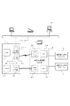
図1は本実施形態で用いられる、画像処理システムの一例を示すブロック図である。
【0020】
[画像処理システム構成の説明]
画像処理装置制御部(10)は、CPU(101)によって制御を行っており、HDD装置(104)や不図示のメモリ等を備える。またネットワークI/F部(102)とVideoI/F部(103)を備え、これらを介してネットワークPDLコントローラ(11)と接続されている。さらに、不図示のI/Fを介して、画像読取装置部(スキャナ)(12)、画像形成装置部(プリンタ)(13)と接続している。また、不図示のキーおよび液晶表示装置を備えたユーザI/F部を備えている。
【0021】
画像形成装置(13)と画像読取装置(12)へのI/Fは専用ハードウェアを用いており、制御信号線とVideoデータ信号線等により構成されている。Videoデータ信号線は、画像データを送信または受信するための信号線であって、制御信号線はVideoデータの送受信のタイミング制御や、各種制御命令を画像読取装置または画像形成装置に対し送信するための信号線である。
【0022】
画像読取装置(12)は、CCD等の画素毎の階調を読み取ることのできる光学センサを備え、原稿台にセットされた原稿の画像を画素毎に読み取り、ラスタービットマップイメージの電子データを生成し、画像処理装置制御部(10)へと送ることができる。構成によっては、画像読取装置(12)にDF(自動原稿送り装置)を備え、複数枚からなる原稿を連続して画像読み取りすることもできる。
【0023】
画像形成装置(13)は、電子写真方式やインクジェット方式といったプリントエンジンを備え、用紙媒体上に、画像処理装置制御部(10)から送られてくる画像データを形成し、機外へと出力することができる。構成によっては、複数の給紙段を備え、異なった複数のサイズ・種類の媒体を選択して給紙し、画像形成することも可能である。また、構成によっては、ある特定のFinishing装置を備え、出力される複数部の原稿をソートしたり、Booklet型にサドル製本するといったことも可能である。
【0024】
画像処理装置制御部(10)では、受け取った画像を圧縮したり、HDD(104)内に保存したり、あるいは所望の方向に回転させたり、所望のサイズに拡大または縮小する、あるいは画素間を保管してラインやエッジを滑らかにするスムージングといった画像データ処理を行うことができる。プリンタ(13)で印刷した調整用画像をスキャナ(12)で読み取って濃度調整するキャリブレーション等の色味調整も行うことができる。
【0025】
画像処理装置制御部(10)は、上述のとおり不図示のメモリも備えており、このメモリはこれら画像データを一時的に保持するだけでなく、画像その他処理の作業領域としても使用する。
【0026】
これらの処理は、主としてCPU(101)で動作する不図示のROMまたはHDD(104)に格納されたプログラムによって、ソフト的に行われるが、高速化のため一部の画像処理をハード化し、ハード的な画像処理部を設けて行うようにもしている。この画像処理ハード回路は、やはりCPU(101)によって、レジスタ等に値を書き込むことによって制御される。
【0027】
また、PDLコントローラ(11)からのラスター画像データを受け取るためのVideoI/F部(103)と、コマンドやステータスのやり取りを行うためのネットワークI/F部(102)を備えている。本実施形態では、イーサ・ネットワークハードウェア上にTCP/IPプロトコル用いて実装しており、多チャンネルのポートを備えたコマンドI/Fとなっているが、多重化さえ可能であれば、IEEE1394やUSB2.0等の他のI/Fハードウェア/プロトコルを用いても、もちろん構わない。
【0028】
ネットワークPDLコントローラ(11)は、CPU(111)で動作するプログラムによって制御されている。外部I/FとしてはネットワークI/F部(112−1)を備えており、外部I/Fを介してホストコンピュータ(14)等に接続される。
【0029】
プリント時においては、ホストコンピュータ(14)上で動作するアプリケーションソフト等により生成された印刷原稿が、同コンピュータ上に搭載されたドライバソフトにより、ページ記述言語(PDL)で記述された印刷ジョブに変換され、これネットワークI/F部(112−1)を介して受け取る。
【0030】
PDLコントローラ(11)は、ホストコンピュータ(14)から受け取ったPDLジョブにより、プリントジョブシーケンスを組み立て、ラスター画像を展開し、画像処理装置制御部(10)に指令を出し画像データを送って、プリントジョブを開始する。
【0031】
また、ホストコンピュータ(14)上などで起動される、スキャンアプリケーションによる指令を受けて、画像処理装置制御部(10)に原稿読み取り指令を送り、送られてきた画像データをホストコンピュータ等に送出するスキャンジョブを実行することも可能となっている。
【0032】
さらには、不図示の操作部を備え、操作部から、PDLコントローラ(11)に内蔵される不図示のHDD装置内に画像データを保存するスキャンジョブを起動したり、テストプリントや以前に転送されてきたプリントジョブの再プリントなどのプリントジョブを起動したりすることも可能である。
【0033】
ネットワークI/F部(112)は画像処理装置制御部(10)と主にコマンドやステータスのやり取りを行うためのコマンドI/Fであって、前述のとおりイーサネット(登録商標)とTCP/IPプロトコルで実現される多チャンネル(ポート)構成となっている。各ポートは、プリントジョブ制御コマンド用ポート(プリントポート)、スキャンジョブ制御コマンド用ポート(スキャンポート)およびプリントスキャンによらず使用される管理コマンド用ポート等がある。この他、VideoI/Fにおける転送タイミングを制御するためのVideo制御ポートもある。
【0034】
VideoI/F部(113)はプリントするラスター画像を画像処理コントローラに送信するためのI/Fである。本実施形態では、CMYK各色8ビット×4色からなるデータ信号、画素クロック信号、ページ同期信号等の制御信号等を並列に送ることのできる多ビットハードウェア信号線群から構成されている。またこれらの多ビット並列信号を、送信側機器で一端直列に並べて、コントローラ−制御部間を十分高速な1ビットシリアル回線で繋ぎ、シリアル信号を受け取った受信側機器で再び多ビット並列信号に直して処理するチャネルリンクと呼ばれる構成を用いることも可能である。
【0035】
メモリ(114)はプログラムの動作上の作業領域や、展開した画像を一時的に格納するためのフレームバッファとしても用いられる。
【0036】
その他、PDLコントローラ(11)には、不図示のHDD装置を備えており、OSや各種制御プログラム、ジョブデータや展開した画像を格納するのに用いられる。もちろん、OSや制御プログラムをROMに格納したり、データや画像をフラッシュメモリなどのRAMメモリ装置に保存する構成にしても構わない。
【0037】
尚、上述の操作部は画像処理装置制御部(10)に内蔵される操作部を、PDLコントローラ(11)も使ったり、あるいはその逆にPDLコントローラ(11)に内蔵される操作部を、画像処理装置制御部も使ったりする兼用構成とすることも可能であり、この場合はコマンドI/Fには操作部制御用コマンドのチャンネル(ポート)が追加される。
【0038】
[コピー時の動作の説明]
図1の画像処理装置制御部(10)と画像読取装置(12)および画像形成装置(13)から成るシステムは、いわゆる複写機として構成されており、コピー動作を行うことが可能である。不図示の操作部のキーによって、ユーザからコピー動作のスタート命令が出されると、画像処理装置制御部(10)はまず、予め設定されたFinishingやカラーモード等のコピーモードに従い、コピージョブのシーケンスを生成する。
【0039】
そして、まず、画像読取装置(12)に対し画像読取指令を出し、画像読取装置(12)の不図示の原稿台にセットされた原稿から、画像データを読み取り、読み取った画像データを、一旦HDD(104)またはメモリ内のフレームバッファに格納する。
【0040】
次に画像形成装置(13)に対し、印刷開始指令を出し、画像形成装置から送られてくる画先同期信号に従い、コピージョブシーケンスに基づく画像順で、HDD(104)またはフレームバッファに格納されている画像データを送出する。
【0041】
このとき、不図示のユーザI/Fで、Finishing動作が指定されているならば、CPU(101)は印刷開始指令時に合わせてFinishing動作モードを指定する。画像形成装置(13)は、モード指定に従って動作を開始し、送られてくる画像を順に用紙媒体上に形成し、Finisherへと出力する。Finisherでは指定されたFinishingモードに従い、特定枚数ごとにステープルやビン送り等の動作を行い、Finishing動作を実行する。
【0042】
画像読取装置(12)に不図示のDFが備えられている場合は、DFにセットされた複数枚の原稿を1枚ずつ連続して画像読取りすることができる。このときの1枚ずつの読取間隔は、画像処理コントローラ(10)の構成に合わせて、CPU(101)で動作するプログラムで指定することができる。例えば、画像処理コントローラが十分な容量のHDD(104)またはメモリを持つ場合は、一旦全ての原稿を読み取って保存し、然る後に画像形成装置にFinishing等の形態に合わせて所望の順に1枚ずつの画像データを送るようにしても良いし、十分な容量がない場合や最初の1枚が出力されるまでの時間(FCOT)を短くしたい場合は、画像読み取り開始と並行して、画像形成装置を起動しておき、1枚画像を読み取る毎に、画像形成装置の画先タイミングに合わせて画像を出力するようにしてもよい。
【0043】
また、読み取った画像のサイズと、画像形成する用紙のサイズや方向のミスマッチを解消すべく、拡大/縮小や回転といった処理の行った後に、画像形成装置(13)に画像出力するようにシーケンスを組むことも可能である。
【0044】
[プリンタと画像処理装置制御部間のI/Fの説明]
本実施形態における画像形成装置(13)は、入力画像として、CMYKカラー多値の画像信号を受けることができる。また画素毎のTAG信号を受けることもできる。TAGビットとは、特定の画素が構成するオブジェクトの種類を特定するものであって、ある画素が文字の一部なのか画像の一部なのかそれともグラフィック図形の一部なのかといった情報などを表すものである。
【0045】
カラー多値画像の場合は、1画素につきCMYK各色8ビットの計32ビット信号を必要とする。その際の画素クロックは、画像形成装置(13)の画像形成速度に合わせて、600dpiの画像を形成することのできるものとなっている。すなわち、本実施形態の画像形成装置では、カラー600dpiの画像形成を基本としている。しかし特定画素に写真画像領域であることを示すTAG信号がついている場合は、画像形成装置(13)内部で隣接する2画素を一組の単位として300dpiで解像度を落とし、階調性を上げて画像形成することも可能である。つまり、TAG信号を、写真画像の領域を表す信号として、文字領域と区別し、それぞれの領域ごとに特性に合わせて、高解像度または高階調性を選択し、良好な画像形成をすることができるようになっている。
【0046】
ハード信号線としては、8ビット×4本(CMYK)とTAG用の1ビット×1本の計5本の信号線を持つ。もちろんそれ以外にタイミング信号線や、プリントに起動をかけたり、JAM等の状態を得る制御信号線もある。
【0047】
タイミング信号とは、ページ毎の画像の先端を示すページシンク信号や、ライン毎の区切りを示すラインシンク信号、および画素の区切りを示す画素クロック信号などである。ページシンク信号は、プリンタ内における用紙の搬送にあわせて、用紙が画像形成装置分に差し掛かったときに、ページの先頭のデータが画像形成装置分に届くタイミングで、プリンタから画像処理装置へ送られる信号である。また、ラインシンク信号は、例えばプリンタが電子写真式プリンタである場合には、レーザポリゴンの回転速度に比例するライン毎の切れ目を示すタイミングとなる。画素クロックは、ラインシンクの1ライン分において600dpiの密度で画素データを送ることのできる同期信号となる。
【0048】
これらの信号線はパラレル信号線としてもよいが、高速なシリアル線を使い両端のドライバにて仮想的に5本+αの信号線を実現することも可能である。
【0049】
[スキャナと画像処理装置制御部間のI/Fの説明]
スキャナ(12)は、原稿画像を8ビット多値のRGBデータとして読み取る。すなわち画像処理装置制御部(10)とのI/Fは、8ビット×RGB3色の24ビット信号およびスキャン動作させるための制御信号およびタイミング信号線より構成される。
【0050】
タイミング信号とは、プリンタとのI/Fの場合と同様に、ページ毎の先端を示すページシンク信号や、1ライン毎の区切りを示すラインシンク信号および画素クロックがあって、これらはスキャナのメカ的な読取速度と光学センサの読取解像度によって定まってくる。
【0051】
[PDLコントローラと画像処理コントローラ間のI/Fの説明]
PDLコントローラ(11)と画像処理装置制御部(10)間の第1のI/Fは、Etherネットを用いたネットワークI/F2(112)である。これはコマンドI/Fであって、主として両コントローラ間での印刷指令やモード指定等といったコマンドや、画像形成装置(13)や画像読取装置(12)がReadyになっているか、あるいはエラー等が起こっているか、といった情報であるステータスのやり取りを行う。プロトコルはTCP/IPを用いて多重化を実現しており、プリントポート、スキャンポート、管理ポート、イベントポートおよびビデオポートを備え、それぞれ並列に独立してコマンド通信を行えるようになっている。
【0052】
第2のI/Fは、画像データの転送を行う、VideoI/F部(113)である。このI/FはCMYK各8ビットの信号と、画像の領域の性質を表す1または2ビットのTAGビット信号線、および信号の画素単位を表す画素クロック、ラインごとの区切りを表すLineイネーブル信号等の信号線が(論理的に)パラレルに送られるように構成されている。物理的に必要本数の信号線を配置してもよいが、それだとケーブルが太くなってしまうので、数本の高速シリアル線を用い、両端のドライバで仮想的に必要本数の信号線を実現している。
【0053】
ネットワークI/F部2(112)は汎用のEtherネットI/Fであり、一度に送れる情報量は比較的少なく、比較的低速のI/Fである。しかしながらTCP/IPを用いており、アドレスやポートを複数設定して、複数種類の情報を一度にやり取りする多チャンネル化が可能である。また、双方向I/Fであり、PDLコントローラ側からも画像処理装置制御部側からもどちらからも所望のコマンドや情報を送ることが可能となっている。
【0054】
これに対し、ビデオI/F部はシステムのパフォーマンスを考慮して専用に設計されており、プリンタの画像形成速度に合わせて十分に高速なデータ転送が可能となっているが、送れる情報は一度に1つの画像データのみの1チャンネルI/Fであり、データ転送方向はPDLコントローラから画像処理装置制御部(10)への1方向I/Fである。
【0055】
[PDLコントローラプロセス構成]
図2はPDLコントローラにおける制御ソフトのプロセス構成とデータ/コマンドフローの一例を、模式的に示した図である。なお、この制御ソフトは、CPU(111)により実行され、模式図に表される各ブロックは、メモリ(114)上に構成されている。
【0056】
206はOSの機能を用いて実現されているTCP/IP通信部を表している。周知のとおりTCP/IPは多重化されており、物理的に一つの回線で接続されている、あるIPアドレスを備える機器に対して、論理的に多数のポートを持って、並列に通信することができる。例えば画像処理装置のIPアドレスが192.168.1.2であるとし、管理ポートは9000に、イベントポートは9001に割り振ると、ポート9000と9001は全く独立に通信動作することが可能である。またそれぞれのポートで用いられるトランスポート層プロトコルは、TCPまたはUDPである。TCPでは接続のセッションを確立してから、データ転送動作を行うので、基本的に送信パケットを相手側が受信したことが保障され、UDPはセッションを確立せずに転送する可能であるので、相手側の受信は保障されないがその分高速である。本実施形態では、イベントポート(Event port)にはUDPを用いており、その他のポートにはTCPを用いて、その上のアプリケーション層プロトコルを実装している。
【0057】
201は管理プロセスである。このプロセスは、画像処理装置制御部(10)の管理ポートと通信し、すべてのプロセスに先んじて起動される。主に、プリント、ビデオ、スキャンといった他のプロセスを順次起動する他、画像処理装置制御部(10)側の静的状態、動的状態等の情報を入手する。例えば後述するポートでジョブシーケンスを送信すると、画像処理装置制御部ソフトはジョブオブジェクトを生成するが、そのジョブの動作(印刷または画像読取)が完了すると、そのジョブオブジェクトは消滅する。この、ジョブオブジェクトの生成・消滅といった情報も、このポートを通じて入手することができる。
【0058】
管理プロセス(201)は、起動するとまず、図3に示す初期化動作を行う。画像処理装置側の管理ポートはTCPの9000番に固定されており、イベントプロセスはOSの機能を用いて、画像処理装置のIPアドレスの9000番ポートに接続に行き、セッションを確立する(S301)。このとき画像処理装置側がサーバとなっており、クライアントであるPDLコントローラ側のポート番号(Admin port)は、任意の番号を用いることができる。セッションの確立時にこのポート番号は、相手側に通知されるので、その後問題なく双方向通信することができる。また、セッションが確立したら、画像処理装置に初期化コマンドを送信し、必要な初期化処理を促す。
【0059】
そして次に、イベントを送ってほしいUDPのポート番号(Event port)を空いているものの内から定め、管理ポート9000を通じて、画像処理装置に知らせる(S302)。画像処理装置はここで知らされたポート番号に、発生したイベントを通知するようになる。
【0060】
Admin portや後述するPrint,Video,Scan portのコマンドは、管理プロセス側から投げられ、それに対して画像処理装置側が返答するという、Command−Replyの組の形式を取ったアプリケーション層プロトコルとなっている。例えば、上述のイベントポート番号の通知は、SetEventコマンドにポート番号と送信してほしいイベントを示すパラメータからなるCommandパケットとなっており、それを受信した画像処理装置は、イベント送信先をセットするとともに、OKのReplyパケット返す。
【0061】
これに対し、Event portは、画像処理装置側からPDLコントローラへの一方通行プロトコルを採っており、画像処理装置は、PDLコントローラが送ったイベントを受信したかどうか確認せず、イベントが発生するたびに次々と送信する。イベントを受け取った管理プロセスは、割り込み処理をして必要な内部処理を行う。
【0062】
次に、画像処理装置側のプリントポート番号を問い合わせる(S303)。すなわち、プリントポート番号の問い合わせは、管理ポートを通じて行われるので、固定値とする必要はなく、画像処理装置は内部状態に合わせて、空いている任意ポート番号を定めることができる。
【0063】
PDLコントローラはReplyでプリントポート番号(Print port)を得ると、プリントプロセス(202)を起動する(S304)。このとき、Printプロセスには、Replyで得たポート番号が通知され、Printプロセスは自身の初期化処理において、画像処理装置のPrintPortに接続することができる。
【0064】
画像処理装置が何らかの都合により、プリント不可能な機器あるいは状態となっていたときは、このReplyにおいてエラーを返すことも可能である。このとき管理プロセスはプリントプロセスを起動しないようにして、無駄にCPUリソースを消費しないようにする構成ももちろん可能である。
【0065】
起動したプリントプロセスと管理プロセスの間では、OSのプロセス間通信の仕組みを用いて、データのやり取りを行うことができる。211から215は、このプロセス間通信を現し、管理プロセスとプリントプロセスの通信には212で現すチャネルを用いている。すなわち、上述のPrintPortの番号をプリントプロセスに通知するのは、この仕組みを用いている。OSによって、プロセス間通信の仕組みには、メッセージキューやパイプあるいはソケットと呼ばれるものがあるが、もちろんどれを用いて実装してもかまわない。本実施形態では、双方向通信チャネルとしているが、片方向通信の仕組みを2チャンネル用いて実装してももちろん構わない。
【0066】
管理プロセスは次に、ステップ305からS308において、プリントプロセスと同様に、ビデオプロセス(203)とスキャンプロセス(204)を起動する。ここまで行った後に、管理プロセスは一端Admin portへの接続セッションを切断し、通常処理状態となる(S309)。通常処理状態とは、各プロセスその他の要求および自身の必要に応じて、Admin portに再度セッションを張り、必要なCommand−Replyのやり取りを行う処理である。すなわち、以後は一組のCommand−Replyの組毎に、Admin portのセッションは接続・切断される。
【0067】
また、起動された個々のプロセスが、ジョブ処理での必要性に応じて、直接Admin portに接続して、情報を入手するということも可能である。Admin portはCommand−Reply毎にセッションが張られるので、このルールさえ守ればサーバ側のOpenするポートは1つでも構わないが、TCPの機能を用いて、サーバ側で多重接続を可能とすることももちろん可能である。このときサーバ側の用意するAdminポートは9000番のみであるが、クライアントはプロセスごとにAdmin用のポートを割り振る必要がある。
【0068】
ビデオプロセス203は起動されると、ビデオI/F制御プロセス(205)を起動する。ビデオI/F制御プロセスは、ドライバ(207)を通じてVideoI/Fハードウェアの制御を行うプロセスで、直接ハードウェアを扱うためタイミング的にシビアであり、別プロセスとしてしる。ビデオI/F制御プロセスは、ビデオプロセスから可能なタイミングを教えてもらい、ページメモリから画像データを転送する。データはCMYKカラー多値の場合膨大な容量となるため、転送処理事態はハードウェア回路により行われ、VideoI/Fに信号同期して転送される。これを制御するためのI/FとしてVideoI/Fドライバ(207)が用意されている。
【0069】
[プリント動作の流れの説明]
図4は、プリントプロセスのプリント時の処理を示した処理フローである。外部I/F(112−1)を介して、ホストコンピュータよりプリントジョブを受け取ると、プリントプロセスは処理を開始し、まず、送られてきたPDLジョブを受信する(S401)。プリントジョブは、PSやPCL,LIPSといった、いわゆるページ記述言語(PDL)で書かれPDLジョブ形式ものであり、ホストコンピュータ等の上で動作しているアプリケーションプログラムから、プリントドライバを介して生成されたものである。すなわちPDLジョブは、各ページの要求する用紙のサイズやメディア、両面/片面指定、カラーモード、Finishingと言った、シーケンスを構築するのに必要な情報(モード指定)と、各ページのPDL形式の画像データを合わせて持っている。
【0070】
そして、受け取ったPDLジョブから、モード指定を抽出する(S402)。これを解析してFinishingや両面等の処理を含めてどの給紙段から何枚ずつ給紙しどの排紙段に出すか、あるいは途中何枚目で給紙段を切り替えるか、といった一連のジョブ・コマンド・シーケンスを組み立てる(S403)。
【0071】
コマンドシーケンスは、StartJob→JobParameterSet(複数回)→StartBinder→BinderParameterSet(複数回)→StartDocument→DocumentParameterSet(複数回)→StartPage→PageParameterSet(複数回)→EndPage→EndDocument→EndBinder→EndJobという流れで送られるコマンドの列である。プリントポートより、各々のコマンドを画像処理装置に送ると、それに対応するReplyが画像処理装置側から送られてくる。
【0072】
ここで、StartJobからEndJobまでが一つのジョブのシーケンスとなる。JobParameterSetは、そのジョブ全体にかかわるパラメータ、例えばユーザ名やパスワード等をセットするコマンドである。
【0073】
一つのジョブ中には複数のバインダー単位を含めることができる。バインダー単位とは、主にFinishingを行う単位を示したもので、StartBinderからEndBinderまでが一つのバインダーを示す。BinderParameterSetはそのバインダにおけるFinishing指定などのパラメータをセットするコマンドである。
【0074】
同様に一つのバインダ中には、複数のドキュメント単位を含めることができる。StartDocumentからEndDocumentまでが一つのドキュメントとなる。ドキュメント単位とは、主にカラーか白黒かといったからモードや、複数ページに渡る画像処理の指定を行う単位である。DocumentParameterSetコマンドでそのドキュメントにおけるこれらのパラメータを指定する。
【0075】
一つのドキュメントは複数のページから構成される。StartPageからEndPageまでが1ページを示し、PageParameterSetによってそのページ固有の処理パラメータを指定する。例えば、ページによって印刷する媒体のサイズが異なる場合には、ここでそのページ固有のサイズが指定される。
【0076】
通常は、1ジョブ中に1バインダ、1ドキュメント、複数ページの構成となっている。図を簡略化するため、ステップS404におけるジョブパラメータ送信は、この通常のジョブ構成における、JobParameterSet,BinderParameterSet,DocumentParameterSetのパラメータを送信することとしている。すなわちジョブシーケンスにおけるStartJobコマンドからDocumentParameterSetまでがジョブ全体に関るパラメータとなる。
【0077】
ステップS404において、ジョブ全体にかかわるパラメータを画像処理装置に送信すると、次にステップS405においてページデータの解析および画像展開を行う。これはページ単位のPDLデータを切り出して、メモリ上のフレームバッファ領域に、ビットマップイメージであるラスターイメージデータとして展開することである。これとともに、そのページのみに指定されるべきパラメータも抽出される。
【0078】
展開した1ページの画像データは、ステップS406において、圧縮して一旦メモリまたはHDDに格納する。
【0079】
そして、次に、ステップS407において、ジョブパラメータと同様にプリントポートを介して、画像処理装置に、そのページのページパラメータ、すなわちStartPageおよびPageParameterSetを送る。
【0080】
このとき、ステップS408において、ビデオプロセスに対し、上述したプロセス間通信の仕組みを用い、そのページの画像送信依頼を出す。ステップS430はプロセス間通信を示しており、いわゆるFIFO動作を行うキューとなっている。プリントプロセスからは、転送要求に付随するパラメータとしてページのIDが送られている。
【0081】
転送依頼を出した後は、ステップS409において、そのページがジョブ中の最終ページであったかどうかを確認する。最終ページでない場合は、ステップS405の処理に戻り、続くページの一連の処理を行う。
【0082】
最終ページであった場合は、ステップS410において、ジョブエンドすなわち、EndDocument,EndBinder,EndJobコマンドを送信し、1ジョブ分の処理終了となる。
【0083】
尚、先に述べたとおり、ジョブ中には複数のバインダ、バインダ中には複数のドキュメントを含むことも可能である。このような場合に対応するため、実際には、ステップS404およびステップS410の処理はジョブ、バインダ、ドキュメントのパラメータ送信およびエンド送信に分割されている。バインダおよびドキュメントのエンド送信の直後には、それぞれ最終バインダあるいはドキュメントであったかどうかの判断が入っており、最終でなかった場合には、それぞれのスタートまでループする構造としている。このようにして、複数バインダおよびドキュメントの処理も可能となっているのである。
【0084】
画像処理装置は、すでに受け取ったページパラメータに基づき、ページ単位でのVideoI/Fからの画像受信の準備を行っている。
【0085】
ビデオポートにおけるページ画像データ送信のコマンドシーケンスは、RequestVideo→VideoStart→VideoI/Fによる画像転送→VideoEndというシーケンスになっている。これは、ハードウェアVideoI/Fの送信開始と終了のタイミングを同期するためのシーケンスである。
【0086】
ビデオプロセスは、ステップS521に示すとおり、スタートすると常にステップS430のキューから、画像転送依頼が届いているかを確認している。転送依頼が来たら、ステップS421において、画像処理装置に対して、受信準備が完了しているかの問い合わせを行う。このとき用いられるのがRequestVideoコマンドであり、ステップS430のキューから得た、転送すべきページのIDを画像処理装置に通知し、転送準備ができているかどうかを確認する。
【0087】
画像処理装置側の受け入れ準備が完了していたら、ステップS423において、ビデオプロセスはビデオI/F制御プロセス(205)に対し、ページIDの示すメモリ領域の画像を転送可能とするように指令する。ビデオI/F制御プロセス(205)は、ハードウェアのページシンク等の同期信号を待ち、同期して画像送信できるようにビデオI/Fのレジスタをセットする。ビデオI/F制御プロセスの準備完了を待って、ビデオプロセスが、画像処理装置にVideoStartコマンドを出し、それのReplyがAckで返った後、すぐに画像処理装置からVideoI/Fに同期信号が出され、画像データの転送処理が開始される。
【0088】
ビデオプロセスはVideoStartコマンドのReplyを受け取ったら、一定のタイミングをもってVideoEndコマンドを送っている。このコマンドがステップS424における転送成功確認のコマンドであって、画像処理装置は転送完了を待って、その結果がOKならば成功を、圧縮保存等の処理が間に合わず正しく転送完了できなかった場合(後述)はNGを、Replyとして返す。このNGは再送要求を兼ねており、同一ページ画像の再転送を要求している意である。
【0089】
従って、転送が失敗した場合は、ステップS423に戻り、同じページIDのページデータを再度転送処理する。成功した場合は、ステップS421の処理に戻って、続くページの転送依頼があれば、再び同じシーケンスを繰り返すようになっている。
【0090】
このように、プリントプロセスとビデオプロセスを別プロセスとすることにより、ある程度のページのRIPおよびパラメータ送信を先行した後には、プリントジョブシーケンス送信と、VideoI/Fにおける画像データ転送処理とを並列に処理することが可能となっている。もちろん、1ジョブのシーケンスを送り終わった後に、そのジョブの画像転送が全ページ完了していなくとも、次のジョブシーケンスを送り始めることが可能となる。
【0091】
[画像処理装置制御部のプリント動作]
画像処理装置制御部(10)は画像データを圧縮しつつ、内蔵するメモリ上のフレームバッファに格納していく。予め設定された圧縮率が十分でなく、フレームバッファがオーバーフローしたり、転送速度に画像処理制御部の処理が追いつかなかった場合は、そのページの転送は失敗となり、圧縮率を再設定するなど転送失敗しにくい条件に内部状態を変更して再送要求を出す。
【0092】
PDLコントローラ(11)から画像処理装置制御部(10)に送られてきた画像データは、フレームバッファに格納後、一旦HDDまたはメモリの特定領域に保存される。このとき、予めプリントポートにて送られてきているジョブシーケンスのFinishingその他の各種モードの設定値により、全ページ分の画像データを受信するまで待つようにしたり、あるいは、1ページ分以上の画像データを受信した時点でプリンタに起動を掛けるようにできる。
【0093】
例えば、ジョブは通常1ページ目から最終ページまで順に並んだ形で画像送信されるが、FaceUp出力である場合には、最終ページから印刷すると、出力が1ページから順に並んだ状態でユーザが受け取れる。このような場合には、一端全ページ分のデータを格納した後にプリンタを起動するのがよい。しかしFinishingする場合には、FaceDown出力であるプリンタでは、Finishing指定された場合は、1ページ目から印刷する必要がある。この場合には、全ページ受信まで待たなくともプリンタ起動することができ、印刷開始時期を早めることもできる。
【0094】
画像形成装置(13)の起動においては、PDLコントローラ(11)から送られてきたジョブシーケンスに基づき、給紙段や両面印刷、Finishing等のモードを指定し、画像形成装置(13)の動作が要求するページ順にて、画像データに関連するページ情報を不図示のメモリ上の内部キューに配置する。このとき少なくとも最初に送信される画像データは、メモリ上のフレームバッファに展開しておき、残りのHDDに格納されている画像データは、フレームバッファが空き次第、順次HDDからメモリに転送されるようにする。
【0095】
そして、画像形成装置(13)からの画先信号に同期して、キューに入っているページ情報の順に、画像データを画像形成装置(13)に送出する。画像形成装置(13)は送られてくる1ページごとの画像を、指定された給紙段の媒体上に形成し、指定されたFinishigを行って機外に排出する。
【0096】
[TAGビット信号]
PDLコントローラ(11)が、ホストコンピュータ(14)からのジョブを、画像に展開をする際に、PDL言語の記述に基づくと、画像の特定領域が文字/グラフィックであるか、それとも写真のようなもともとビットマップの画像であるかを判別することができる。PDLコントローラ(11)は、ラスターイメージへの展開時に、これらの情報を合わせて領域情報として保存しておく。これを、画像処理装置制御部(10)に対するTAG信号の生成に用いることができる。
【0097】
言ってみれば、これは「画素単位パラメータ」であって、画像処理装置制御部(10)はこのTAG信号を画像データと共にVideoI/Fよりハード的に受け取り、これを用いて、画素単位で最適の画像処理を行って、出力を行うことができる。
【0098】
[PDLコントローラの圧縮機能]
PDLコントローラ(11)は、展開したラスター画像の圧縮および展開機能を備えている。ラスター展開した画像データを、一旦圧縮してHDDに保存し、VideoI/Fにおける画像データ転送時に、再びフレームバッファ上に展開する。これによって、前のページの転送が終わっていなくとも、画像展開を、HDDの容量など処理の可能な範囲で先行して行っておくことが可能である。
【0099】
[その他のプリント動作の特徴]
本実施形態のPDLコントローラでは、PDL言語としてPostScript(PS)を処理することができるようにしている。しかし、その他PCL,PDF,LIPS等の複数のPDLデータを処理するように構築することももちろん可能である。
【0100】
また、ユーザはドライバ(PPD)にて所望する画像の画質の高低を指定できる。この指定によって、PDLコントローラは、この指定をもって、HDDに一時格納する画像の圧縮率の高低を調整し、画質劣化の度合いを調整することができる。
【0101】
[スキャン動作の流れの説明]
次に、図5を用いて、スキャンプロセス(204)におけるスキャン動作について説明する。
【0102】
スキャンプロセス(204)は、ホストコンピュータ(14)よりスキャン動作の要求を受け取ると(S501)、同時に指定されてくるモード指定情報を抽出する(S502)。モード指定情報とは、読み取る画像をRGBカラー多値として読み込みたいのか、白黒として読み込みたいのか、あるいは原稿に応じて自動でカラー・白黒を切り替えて読み取りたいのか、というカラーモード指定や、読み取る画像がプラテンガラス上にセットされた1枚の画像なのか、あるいは自動原稿送り装置(DF)にセットされた複数枚からなるドキュメントなのか、という読取モード指定の指定、あるいは画像を読み取る範囲の座標情報間などである。
【0103】
そして、ステップS503において、抽出した情報を元に、ジョブシーケンスを構築する。スキャンジョブのコマンドシーケンスは、StartScanJob→ScanParameterSet→EndScanJobの3つのコマンドから構成される。ただし、ScanParameterSetに関しては必要なパラメータの数に応じて複数回連続で送ることができる。
【0104】
ステップS504において、このジョブシーケンスを画像処理装置制御部(10)にスキャンポートを介して送信する。このジョブシーケンスは、あくまで画像処理装置制御部(10)に読取動作の開始を指示するだけのものである。読み取った画像データをPDLコントローラ側に吸い上げるには、また別のコマンド群を用いている。
【0105】
ジョブシーケンスを受け取った画像処理装置制御部(10)側においては、セットされてきたパラメータに基づくモードで、画像読取装置(12)を起動する。そしてハードウェアのSync信号に合わせて画像読取装置(12)から送られてくる画像データを受け取り、内蔵するメモリまたはHDD装置(104)に、ページ毎に順次格納してゆく。
【0106】
ステップS505においては、スキャンプロセスは画像処理装置制御部(10)に対し、1ページ分の画像読み込みが完了したかどうかを問い合わせている。このコマンドは、RetrieveRequestであり、画像処理装置制御部(10)はそのReplyでOK/Not yetを返す。OKの場合は、少なくとも1ページ分の画像データが読み取られ、圧縮されて画像処理装置制御部(10)内のメモリ領域またはHDD装置(104)に格納されている状態で、PDLコントローラに対し画像データ転送できる状態となったことを示す。このときのReplyにはページIDが不可されている。このページIDは、読み取ったページの順となっている。尚、Not yetのリプライのときは、まだ読み取り動作中であって格納が完了していない。このときスキャンプロセスは一定時間を置いて、ステップS505の処理を繰り返すことになる。
【0107】
ステップS506でスキャンプロセス(204)は、RetrievePageコマンドをRequesutで受け取ったページIDと共に送り、そのReplyに付随するデータとして、ページデータを受け取る。ここで画像がカラーRGB多値の場合は、JPEG圧縮されたデータが送られてくる。白黒2値の場合はJBIG圧縮されたデータとなる。つまり、スキャンポートによって画像データを受信するわけである。
【0108】
いずれの場合も単なるパラメータの場合とは異なり、非常に大きなバイト列となるため、このReplyパケットはいくつかに分割されて送られる。スキャンポートは説明してきたとおりイーサネット(登録商標)上に多重チャンネルの一つとして構築されているので、転送スピードは大したものではない。従って、読み取りパラメータをあまり高画質に設定すると、すなわちそれは低圧縮画像となって容量がさらに巨大になり、パフォーマンスが出ないことになる。尚、画像読取装置(12)と画像処理装置制御部(10)との間の画像転送は、VideoI/Fと同様の画像転送専用ハードウェア信号線を用いているので、画像読取装置(12)の読取速度に合わせた転送が可能である。よってこれらのことを加味し、十分なパフォーマンスが出てそれなりの画質を得られる圧縮率を設定する必要がある。これはネットワークI/F自体のスピードにも依存する。
【0109】
受け取りが完了したページIDの画像に対しては、消去要求DeletePageを、ページIDをパラメータとして付随して送る。これを受け取った画像処理装置制御部(10)は内蔵メモリ領域またはHDDから、そのページ画像を消去する。
【0110】
画像データの読み込みが終わったページデータは、順次ホストコンピュータにデータ送信してゆく(S507)。もちろん図5のように、ページごとに順次ホストに送るのではなく、最終ページまで読み取ってから、ジョブ全体のページをまとめて(あるいは順番を並べかえて)送信するようにしてもよい。また、ビデオとプリントの関係のように、専用にホストコンピュータへの画像送信用プロセスを持つ構成とし、画像処理装置制御部(10)からの読取処理とホストへの送信処理を並列に行うようにすることももちろん可能である。
【0111】
そして、ステップS507において、画像処理装置制御部(10)から受け取った画像が、最終ページであったがどうかを確認する。これはLastPageCheckコマンドによって行われ、ReplyでYes/Noが返される。最終ページでないばあいには、ステップS505まで戻り繰り返す。最終ページであったなら、そのスキャンジョブは完了となる。
【0112】
尚、ここではホストコンピュータ(14)からジョブが来てホストコンピュータに画像データを送る場合について説明したが、PDLコントローラ(11)自身の操作部からジョブを送り、PDLコントローラ(11)内に格納して完了としたり、あるいはPDLコントローラ(11)内に格納してある画像を、例えばEmail添付の形で、任意のアドレスで送ったりするようにすることも、もちろん可能である。PDLコントローラへの読取格納までの指示のみをホストコンピュータが出すようにしたり、すでにPDLコントローラ内に格納されている画像データをホストコンピュータ側から取り出したりすることももちろん可能である。さらには、PDLコントローラ内部に格納されている画像データを、プリントポートで送るプリントジョブにマージしてプリント処理するといったユーティリティへの応用も考えられる。いずれにせよ、図5の本質的な部分は、スキャンプロセス(204)と画像処理装置制御部(10)との間の制御である。
【0113】
[プリントとスキャンの並列動作]
以上述べてきたように、本実施形態のPDLコントローラによれば、ホストコンピュータからのプリント指令の実行と、他のホストコンピュータからのスキャン指令の実行を、パフォーマンスに影響させずに並列に処理することが可能となる。
【0114】
外部ホストに対するプリント用のポートは、図1における外部ネットワークI/F部1(112−1)を介して、トランスポート層のTCP/IPプロトコル上に実装されている。例えば、LPRプロトコル用としては、515番ポートを、Port9100用としては9100〜9103ポートまでをプリント用として開いている。PDLコントローラ(11)はサーバとして動作しており、プリント用ポートは多重化されているため、同一ポート番号であっても複数のクライアントPCと接続可能である。
【0115】
スキャン用ポートについてももちろん、専用に1ポート割り当てても良いが、プリント用ポートと兼用することも可能である。すなわち、スキャンユーティリティ(あるいはドライバ)に、サーバに接続した時点で、自身がスキャン用として接続したい旨を通知するプロトコルとし、サーバ側では外部ポートに対し接続の振り分けプロセスを起動しておき、スキャン用ユーティリティと判別した際には、Scanプロセスに接続させるようにすればよい。
【0116】
プリントに関しては、同時に複数のクライアントから印刷要求が来ても、ジョブだけ受け取っておけばクライアント側は開放される。受け取ったジョブは内部でキューイングしておき、実際のプリント動作は順に実行すればよい。
【0117】
スキャンに関しては、通常スキャナを動かし、読み取った画像をクライアントに返すという作業が必要になるため、1台のクライアントがスキャンプロセスに接続している状態では他のクライアントは接続しない方が良い。従って振り分けプロセスにおいては、1台のクライアントが接続されている状態では、他のクライアントにはビジーを返すようにしている。
【0118】
このように、クライアント側の接続に関しては、プリントと(一つの)スキャンの並列動作については全く支障がない。問題は画像データの転送部であって、ここが共通のVideoI/F部を使用していると、PDLコントローラ(11)内でビデオプロセスが画像転送中である場合には、スキャンジョブは待たされ、さらにはスキャンプロセスに接続しているクライアントPC自体も処理を待たされることになる。また、VideoI/Fというハードウェアリソースを、プリントとスキャンという別のプロセスが使用することになるので、排他制御等が必要となって、処理も若干複雑になる。
【0119】
しかし、上記で示してきたとおり、本実施形態では、VideoI/Fはプリント用画像データ専用の転送経路としているため、PDLコントローラと画像処理装置間でのプリントとスキャンの画像転送は、互いに影響することなく、完全に並列に行うことができる。
【0120】
コマンド通信路であるネットワークI/Fは、スキャン以外のプロセスは、通常、コマンドとそれに付随するパラメータ以外は送受信しないため、帯域幅のほとんどをスキャンデータ転送に使用することが可能であるため、双方向VideoI/F通信路を用いるときよりは、若干転送パフォーマンスは劣るが、コマンド通信路でプリントもスキャンもどちらのデータも転送する場合よりは有利となる。
【0121】
また、スキャンデータ転送にコマンド通信路を用いることにより、画像処理側で予めJPEG/JBIG等の圧縮を行っておく必要があるため、画質的にはVideoI/Fを用いた場合よりも落ちることになるはずである。しかし、実際には、PDLコントローラからホストコンピュータへの画像転送もネットワークを介してであるため、PDLコントローラがラスター・データを取り込めたとしても、どのみちホストに転送する場合には圧縮が必要であるため、スキャン画質に対する影響はない。
【0122】
もちろん、ホストおよび画像処理装置の両方に、ギガビット・イーサのような広帯域ネットワークI/Fを用いることができる場合には、ラスター・データをPDLコントローラに取り込みホストへ送信するようにする系も、もちろん実装可能である。その場合であっても、プリントとの並列同時動作において、本発明がパフォーマンス的に有効であることは明らかである。
【0123】
以上説明してきたように、本実施形態によれば、双方向に制御データの通信を行うネットワークI/F部と、単方向に画像データの通信を行うVideoI/F部とを使用して、PDLコントローラと画像処理装置制御部との間でのデータ通信を行う画像処理システムにおいて、PDLコントローラ及び画像処理装置制御部がスキャン動作する場合に、画像データの通信のために、ネットワークI/F部を使用するように制御した。
【0124】
特に、スキャン動作とプリント動作の並列動作を行う場合において、スキャン入力のためにネットワークI/F部を使用し、プリント出力のためにVideoI/F部を使用することにより、装置のコストアップを招くことなく、既存の通信路の性能を最大限に生かした、並列動作に適した画像データ通信ができる。
【0125】
また、PDLコントローラはホストへの送信のために圧縮された画像データを必要とするので、画像処理装置制御部で入力画像データを圧縮させ、圧縮した画像データをネットワークI/F部を使用して受信するように制御した。これにより、及び各インタフェース部の帯域と転送データ量との最適化が図れ、効率的な画像データ通信ができる。
【0126】
(第2の実施形態)
タイミング処理等、ソフト構成上問題がないならば、ビデオI/F制御プロセスは、ビデオプロセス内で同等の処理を行い、あえて別プロセスとしない構成をとることも可能である。また、プリントシーケンスをシーケンシャルに処理するならば、ビデオプロセス自身も独立プロセスとせず、プリントプロセス内で処理するようにする構成ももちろん可能である。この場合、画像処理装置制御部側のポート構成も、PrintとVideoを兼ねて一つのポート番号のみを用いるようにできる。この場合のプロセス構成図を図4に示す。
【0127】
尚、第1の実施形態で述べたPDLコントローラからのホストコンピュータに対するポートと同様に、PrintとScanのポートを共通化することももちろん可能であるが、この場合は、画像処理装置制御部側に振り分けタスク等の仕組みを実装する必要があり、またこのネットワークI/F(112−2)は、PDLコントローラ−画像処理装置間専用であるため、特にポートが不足する等の問題もないので、各々専用ポートとしている。さらに、接続するクライアントとなる、PDLコントローラ側のプロセスも、基本的に1プロセスであるため、特にポートを多重化してはいない。
【0128】
このようなプロセス構成とした場合、プリント処理のシーケンスは、図7に示すものとなる。
【0129】
プリント&ビデオプロセス(以下プリントプロセス)は、まず、ステップS701において、外部I/F(112−1)を介して、ホストコンピュータ(14)よりPDLジョブ形式のプリントジョブを受け取る。
【0130】
そして、ステップS702において、受け取ったPDLジョブから、モード指定を抽出し、解析してFinishingや両面等の処理を含めてどの給紙段から何枚ずつ給紙しどの排紙段に出すか、あるいは途中何枚目で給紙段を切り替えるか、といった一連のジョブシーケンスを組み立てる。
【0131】
それと共に、ステップS704において、PDLジョブ内の全ページの画像データ部分を取り出し、メモリ上のフレームバッファ領域に、ビットマップイメージであるラスターイメージデータに展開する。展開した画像データは、ステップS705にて、圧縮して一旦メモリまたはHDDに格納する。本実施形態においては、画像データの転送は、全ページ連続してまとめて行うので、ジョブの全ページについて展開・圧縮・保存しておく。
【0132】
そして、次にステップS706において、画像処理装置との内部ネットワークI/F(112−1)上のプリントポートを介して、画像処理装置制御部(10)に、構築したジョブシーケンスを実現するコマンドシーケンスを通知する。これは、第1の実施形態で述べた、StartJobからEndJobまでの一連のコマンドシーケンスである。もちろん、ジョブ内に複数バインダ、ドキュメント内に複数ドキュメントを含んでいても構わない。
【0133】
画像処理装置制御部(10)では、受け取ったジョブシーケンスに基づき、VideoI/F部での画像受信の準備を行う。1ページでも準備が完了している状態となっていれば、ステップS707にて、PDLコントローラから送られてくるRequestVideoコマンドに対して、転送して欲しい最初のページIDをReplyに付けて返すのは、第1の実施形態のVideoポートでの動作と同様である。
【0134】
ステップS708、709の画像データ転送および再送処理についても、第1の実施形態のビデオプロセスおよびビデオI/F制御プロセスと同様である。プリントプロセスは、ハードウェアのページシンク等の同期信号を待ち、同期して画像送信できるようにビデオI/Fをセットしてから、画像処理装置制御部(10)にVideoStartコマンドを出す。そのReplyがAckで返れば、すぐに画像処理装置制御部(10)からVideoI/Fに同期信号が出され、画像データが転送処理が開始される。転送完了後はVideoEndコマンドを送り、そのReplyによって、同一ページを再送するか、次のページの画像を送るかを判断する。
【0135】
ステップS710においては、今送った画像が最終ページであったかどうかを判断する。これは送ったジョブのコマンドシーケンスに基づくので、第1の実施形態とは異なり、特に画像処理装置に問い合わせに行く必要はない。
【0136】
プリントジョブシーケンスの全ページ分の画像転送を確認したら、プリントプロセスにおけるジョブの処理は完了となる。
【0137】
(他の実施形態)
以上の2つの実施形態は、画像読取装置と画像形成装置を備えるデジタル複写機と、それに接続されるコントローラ装置から構成されるシステムについて説明してきたが、本発明はこれに限定されるものではなく、複数の画像処理デバイスを備え同数以上のデータ転送可能な入出力通信経路を備える画像処理装置とそれに接続されるコントローラ装置から構成されるシステムであれば、適用可能であることは自明である。
【0138】
また、画像データの転送方向については、1つあるいは一部の通信経路が一方向であることが本質的であって、その方向がコントローラ装置から画像処理装置であってもその逆であってもどちらでも構わない。さらには、残りの通信経路で送られる画像データの転送方向が反対方向である必要もなく、接続されるデバイスに応じて、どちらの転送方向も同じであってももちろん差し支えない。
【0139】
また、上記実施形態では、スキャン動作のためにネットワークI/F部をプリント動作のためにVideoI/F部を固定的に割り当てているが、スキャンジョブとプリントジョブが並列に実行されるときだけ、以上のような割り当てとし、一方で、直列に実行される限りは両方の動作に関してVideoI/F部を共有して使用するようにしてもよい。
【0140】
また、本発明は、前述した実施の形態の機能を実現するソフトウェアのプログラムコードを記憶した記憶媒体をシステムあるいは装置に供給し、そのシステムあるいは装置のコンピュータ(またはCPUやMPU)が記憶媒体(ホスト14が備える記憶媒体、メモリ114等)に格納されたプログラムコードを読み出し実行することによっても、完成されることは言うまでもない。
【0141】
この場合、記憶媒体から読み出されたプログラムコード自体が前述した実施形態の機能を実現することになり、そのプログラムコードを記憶した記憶媒体は本発明を構成することになる。プログラムコードを供給するための記憶媒体としては、例えば、フロッピー(登録商標)ディスク、ハードディスク、光ディスク、光磁気ディスク、CD−ROM、CD−R、磁気テープ、不揮発性のメモリカード、ROMを用いることができる。また、コンピュータが読み出したプログラムコードを実行することにより、前述した実施形態の機能が実現されるだけではなく、そのプログラムコードの指示に基づき、コンピュータ上で稼動しているOSなどが実際の処理の一部または全部を行い、その処理によって前述した実施形態の機能が実現される場合も含まれることは言うまでもない。
【0142】
さらに、記憶媒体から読み出されたプログラムコードが、コンピュータに挿入された機能拡張ボードやコンピュータに接続された機能拡張ユニットに備わるメモリに書きもまれた後、次のプログラムコードの指示に基づき、その拡張機能を拡張ボードや拡張ユニットに備わるCPUなどが処理を行って実際の処理の一部または全部を行い、その処理によって前述した実施形態の機能が実現される場合も含まれることは言うまでもない。
【0143】
また、このような記憶媒体を含む装置をネットワーク上に配置させておき、記憶媒体に記憶されたプログラムをネットワークを介して所定の装置へダウンロードし、ダウンロードしたプログラムを実行することによっても、本発明の上記実施形態の機能が実現されることは言うまでもない。
【0144】
【発明の効果】
以上説明してきたように、本発明によれば、第1の画像処理装置と第2の画像処理装置との間で双方向に制御データの通信を行う第1通信手段と、第1の画像処理装置から第2の画像処理装置へ単方向に画像データの通信を行う第2通信手段とを使用して、第1の画像処理装置と第2の画像処理装置との間でのデータ通信を行う際に、第2の画像処理装置から第1の画像処理装置への画像データの通信において、画像データの通信のために第1通信手段を使用するように第1通信手段を制御することことにより、画像データの通信に係る構成のコストアップを招くことなく、第1の画像処理装置と第2の画像処理装置との間の画像データの通信に応じた最適な画像データ通信ができるという効果がある。
【0145】
また、本発明によれば、第1の画像処理装置と第2の画像処理装置との間で双方向に制御データの通信を行う第1通信手段と、第1の画像処理装置から第2の画像処理装置へ単方向に画像データの通信を行う第2通信手段とを使用して、第1の画像処理装置と第2の画像処理装置との間でのデータ通信を行う際に、圧縮された画像データを第1の画像処理装置が必要とする場合、第2の画像処理装置から第1の画像処理装置への圧縮画像データの通信のために第1通信手段を使用するように第1通信手段を制御することにより、圧縮された画像データを必要とする場合において効率的な画像データ通信ができるという効果がある。
【図面の簡単な説明】
【図1】本発明に係る画像処理システムのシステム構成を示すブロック図である。
【図2】第1の実施形態における、PDLコントローラの制御プログラムのプロセス構造とデータフローの一例を示すブロック図である。
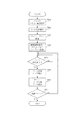
【図3】第1の実施形態における、管理プロセスの起動時の処理を示したフローチャートである。
【図4】第1の実施形態における、プリント時のプリントプロセスおよびビデオプロセスの、処理の一例を示すフローチャートである。
【図5】第1の実施形態における、スキャン時時のスキャンプロセスの、処理の一例を示すフローチャートである。
【図6】第2の実施形態における、PDLコントローラの制御プログラムのプロセス構造とデータフローの一例を示すブロック図である。
【図7】第2の実施形態における、プリント時のプリントプロセスおよびビデオプロセスの、処理の例を示すフローチャートである。
【符号の説明】
10 画像処理装置制御部
11 PDLコントローラ
12 画像読取装置
13 画像形成装置
14 ホストコンピュータ
101 CPU
102 ネットワークI/F部
103 VideoI/F部
104 HDD装置
111 CPU
112 ネットワークI/F部2
112−1 ネットワークI/F部1
113 VideoI/F部
114 メモリ[0001]
BACKGROUND OF THE INVENTION
The present invention relates to an image processing apparatus capable of communicating with an image processing apparatus, such as a control unit of a digital copying machine, a data communication method, and a program.
[0002]
[Prior art]
2. Description of the Related Art Conventionally, a PDL controller that expands an image of each page of a print job described in PDL and generates raster image data has been used. This PDL controller is connected to an image processing apparatus such as a copying machine via a command I / F for exchanging commands and a Video I / F for exchanging video image data, and a PDL print image processing system It is used as
[0003]
The PDL controller analyzes a PDL job received from a host computer connected via a network or the like and forms a raster image. Then, a command sequence constructed based on the analysis result is sent to the control unit of the image processing apparatus via the command I / F, and after that, in parallel, the image data is sent via the Video I / F. . Based on the received command sequence and image data, the image processing apparatus control unit activates the image forming apparatus unit to form an image on a paper medium and outputs the image to the outside. A PDL controller having such a function is disclosed in, for example, Japanese Patent Application Laid-Open No. 2001-027939.
[0004]
On the other hand, the PDL controller may also serve as a scan controller, and the connected image processing apparatus is not only equipped with an image forming apparatus such as a printer, but the image forming apparatus such as a copier and the image reading apparatus are combined. Connected to the image processing apparatus.
[0005]
In this conventional scanable image processing system, Video I / F which is an image transfer path is used for image data transfer between the controller and the image processing apparatus. This Video I / F uses bi-directional communication hardware, and can switch the direction of data transfer from the controller to the image processing apparatus during printing and from the image processing apparatus to the controller during scanning.
[0006]
[Problems to be solved by the invention]
However, such a PDL print image processing system has the following problems. That is, normally, for printing from a host computer, a printer driver is activated from application software that created a document, and a print command is issued to the printer controller device via an I / F such as a network. On the other hand, in scanning, a scan application is started on the host computer and a scan command is issued to the controller device, waiting for an image to be sent, or a scan command is issued from an operation unit provided in the controller device itself. The image data is temporarily stored in a storage unit such as a hard disk device of the controller device. Thereafter, a general work flow is to send image data from the operation unit to the host computer or download an image stored from the host computer.
[0007]
In the above-described conventional image processing system, since bidirectional Video I / F of the same hardware is used, either one of the parts of the image processing apparatus used for the printing work and the scanning work is different, but either one is used. In the case of work, the user who wants to perform the other work has to wait until the work in progress is completed. At this time, if printing is performed during scanning, the print job can be thrown normally from the user's point of view, so there is no problem as long as the job start is delayed, but the user who wants to scan during the printing operation Was supposed to be unable to do anything until the printing was finished.
[0008]
Further, as described above, it is necessary to use bi-directional hardware as the Video I / F used for image transfer, leading to an increase in the cost of the system.
[0009]
In addition, a network I / F such as Ethernet (registered trademark) is often used for the I / F between the controller device and the host computer. In this case, it is impossible in terms of capacity to send a bitmap raster image as it is. Even if a high-quality raster image is read into the controller device, irreversible compression with a high compression rate accompanied by image quality degradation is eventually performed in the controller device. After that, it is necessary to transfer the image data to the host computer, and the high-quality bidirectional Video I / F with high image quality is wasted.
[0010]
The present invention is for solving the above-described problems, using a first communication means for communicating control data bidirectionally and a second communication means for communicating image data unidirectionally, When performing data communication with another image processing apparatus, controlling the use of the first communication means for image data communication increases the cost of the configuration related to image communication. It is another object of the present invention to provide an image processing apparatus, a data communication method, and a program capable of optimal image data communication according to a desired state of image input / output operation.
[0011]
In addition, the present invention uses a first communication unit that communicates control data in both directions and a second communication unit that communicates image data in a single direction, and communicates with other image processing apparatuses. When compressed image data is required when performing data communication, compression is performed by controlling to use the first communication means for receiving compressed image data from another image processing apparatus. An object of the present invention is to provide an image processing apparatus, a data communication method, and a program capable of performing efficient image data communication when the image data thus obtained is required.
[0012]
[Means for Solving the Problems]
The present invention is an image processing apparatus capable of communicating with another image processing apparatus, the first communication means for bidirectionally communicating control data with the other image processing apparatus, and the other image processing In communication of image data in one direction with the image processing apparatus from the image processing apparatus to the other image processing apparatus, and in communication of image data from the other image processing apparatus to the image processing apparatus. And control means for controlling the first communication means so as to use the first communication means for receiving the image data from the other image processing apparatus.
[0013]
The present invention is also an image processing apparatus capable of communicating with another image processing apparatus, the first communication means for bidirectionally communicating control data with the other image processing apparatus, and the other Second communication means for unidirectionally communicating image data with the image processing apparatus from the other image processing apparatus to the image processing apparatus; and image data from the image processing apparatus to the other image processing apparatus. In the communication, control means for controlling the first communication means so as to use the first communication means for transmitting image data to the other image processing apparatus.
[0014]
The present invention also provides a first communication means for bidirectionally communicating control data between the first image processing apparatus and the second image processing apparatus, and the second image from the first image processing apparatus. Data communication for performing data communication between the first image processing apparatus and the second image processing apparatus using second communication means for performing communication of image data in one direction to the image processing apparatus In the method of communicating image data from the second image processing apparatus to the first image processing apparatus, the first communication means is configured to use the first communication means for image data communication. It is characterized by controlling.
[0015]
The present invention also provides a first communication means for bidirectionally communicating control data between the first image processing apparatus and the second image processing apparatus, and the second image from the first image processing apparatus. Data communication for performing data communication between the first image processing apparatus and the second image processing apparatus using second communication means for performing communication of image data in one direction to the image processing apparatus A method for communicating compressed image data from the second image processing device to the first image processing device when the first image processing device requires compressed image data. The first communication means is controlled to use the first communication means.
[0016]
The present invention also provides a first communication means for bidirectionally communicating control data between the first image processing apparatus and the second image processing apparatus, and the second image from the first image processing apparatus. Data communication for performing data communication between the first image processing apparatus and the second image processing apparatus using second communication means for performing communication of image data in one direction to the image processing apparatus A computer-executable program for executing the method, wherein the first communication for communication of image data in communication of image data from the second image processing apparatus to the first image processing apparatus The first communication means is controlled to use the means.
[0017]
The present invention also provides a first communication means for bidirectionally communicating control data between the first image processing apparatus and the second image processing apparatus, and the second image from the first image processing apparatus. Data communication for performing data communication between the first image processing apparatus and the second image processing apparatus using second communication means for performing communication of image data in one direction to the image processing apparatus A computer executable program for executing the method, wherein the first image processing device requires compressed image data from the second image processing device to the first image processing device. The first communication means is controlled to use the first communication means for communication of compressed image data.
[0018]
DETAILED DESCRIPTION OF THE INVENTION
Embodiments of the present invention will be described below with reference to the drawings.
[0019]
(First embodiment)
FIG. 1 is a block diagram showing an example of an image processing system used in this embodiment.
[0020]
[Description of image processing system configuration]
The image processing device control unit (10) is controlled by the CPU (101), and includes an HDD device (104), a memory (not shown), and the like. In addition, a network I / F unit (102) and a video I / F unit (103) are provided, and are connected to the network PDL controller (11) through these. Furthermore, it is connected to an image reading device (scanner) (12) and an image forming device (printer) (13) via an I / F (not shown). In addition, a user I / F unit including a key and a liquid crystal display (not shown) is provided.
[0021]
The I / F to the image forming apparatus (13) and the image reading apparatus (12) uses dedicated hardware, and is composed of a control signal line, a video data signal line, and the like. The video data signal line is a signal line for transmitting or receiving image data, and the control signal line is for transmitting / receiving timing control of video data and for transmitting various control commands to the image reading apparatus or the image forming apparatus. This is a signal line.
[0022]
The image reading device (12) includes an optical sensor capable of reading the gradation of each pixel, such as a CCD, and reads an image of the document set on the document table for each pixel to generate electronic data of a raster bitmap image. Then, it can be sent to the image processing apparatus control unit (10). Depending on the configuration, the image reading device (12) may be provided with a DF (automatic document feeder), and images of a plurality of documents can be read continuously.
[0023]
The image forming apparatus (13) includes a print engine such as an electrophotographic system or an inkjet system, forms image data sent from the image processing apparatus control unit (10) on a paper medium, and outputs the image data to the outside. be able to. Depending on the configuration, a plurality of paper feed stages may be provided, and a plurality of different sizes and types of media may be selected and fed to form an image. Further, depending on the configuration, a specific finishing device may be provided, and a plurality of output originals may be sorted or saddle bound into a booklet type.
[0024]
In the image processing device control unit (10), the received image is compressed, stored in the HDD (104), rotated in a desired direction, enlarged or reduced to a desired size, or between pixels. Image data processing such as smoothing that stores and smoothes lines and edges can be performed. Color adjustment such as calibration for adjusting the density by reading the adjustment image printed by the printer (13) with the scanner (12) can also be performed.
[0025]
As described above, the image processing apparatus control unit (10) also includes a memory (not shown). The memory not only temporarily stores these image data but also is used as a work area for images and other processing.
[0026]
These processes are performed in software by a program stored in a ROM (not shown) or an HDD (104) that is mainly operated by the CPU (101), but some image processing is hardwareized to increase the speed. A typical image processing unit is also provided. This image processing hardware circuit is also controlled by the CPU (101) writing a value in a register or the like.
[0027]
In addition, a video I / F unit (103) for receiving raster image data from the PDL controller (11) and a network I / F unit (102) for exchanging commands and statuses are provided. In this embodiment, the TCP / IP protocol is implemented on the Ethernet network hardware, and the command I / F is provided with a multi-channel port. However, as long as multiplexing is possible, IEEE1394 or Of course, other I / F hardware / protocol such as USB 2.0 may be used.
[0028]
The network PDL controller (11) is controlled by a program operating on the CPU (111). The external I / F includes a network I / F unit (112-1) and is connected to the host computer (14) and the like via the external I / F.
[0029]
At the time of printing, a print document generated by application software or the like running on the host computer (14) is converted into a print job described in page description language (PDL) by driver software installed on the computer. This is received via the network I / F unit (112-1).
[0030]
The PDL controller (11) assembles a print job sequence based on the PDL job received from the host computer (14), develops a raster image, sends a command to the image processing device controller (10), sends image data, and prints. Start the job.
[0031]
In response to a command from a scan application activated on the host computer (14) or the like, a document reading command is sent to the image processing apparatus control unit (10), and the sent image data is sent to the host computer or the like. It is also possible to execute a scan job.
[0032]
Furthermore, an operation unit (not shown) is provided, and from the operation unit, a scan job for saving image data in an HDD device (not shown) built in the PDL controller (11) is started, a test print or a previous transfer is performed. It is also possible to activate a print job such as reprinting a print job that has been received.
[0033]
The network I / F unit (112) is a command I / F mainly for exchanging commands and status with the image processing apparatus control unit (10). As described above, the Ethernet (registered trademark) and the TCP / IP protocol are used. The multi-channel (port) configuration realized by Each port includes a print job control command port (print port), a scan job control command port (scan port), a management command port that is used regardless of print scanning, and the like. In addition, there is a Video control port for controlling the transfer timing in the Video I / F.
[0034]
The Video I / F unit (113) is an I / F for transmitting a raster image to be printed to the image processing controller. In this embodiment, it is composed of a multi-bit hardware signal line group capable of sending in parallel data signals such as 8 bits × 4 colors of CMYK, control signals such as pixel clock signals, page synchronization signals, and the like. In addition, these multi-bit parallel signals are serially arranged in series at the transmitting device, the controller and the control unit are connected by a sufficiently fast 1-bit serial line, and the receiving device receiving the serial signal converts it back to a multi-bit parallel signal. It is also possible to use a configuration called a channel link for processing.
[0035]
The memory (114) is also used as a work area for program operation and as a frame buffer for temporarily storing the developed image.
[0036]
In addition, the PDL controller (11) includes an HDD device (not shown), and is used to store an OS, various control programs, job data, and developed images. Of course, the OS and control program may be stored in the ROM, and data and images may be stored in a RAM memory device such as a flash memory.
[0037]
Note that the above-described operation unit uses the operation unit built in the image processing apparatus control unit (10) and also uses the PDL controller (11), or vice versa, the operation unit built in the PDL controller (11). It is possible to use a shared configuration in which the processor control unit is also used. In this case, a command channel (port) for controlling the operation unit is added to the command I / F.
[0038]
[Description of copy operation]
The system including the image processing apparatus control unit (10), the image reading apparatus (12), and the image forming apparatus (13) shown in FIG. 1 is configured as a so-called copying machine and can perform a copying operation. When a user issues a copy operation start command using an operation unit key (not shown), the image processing apparatus control unit (10) first performs a copy job sequence in accordance with a preset copy mode such as finishing or color mode. Is generated.
[0039]
First, an image reading command is issued to the image reading device (12), image data is read from a document set on a document table (not shown) of the image reading device (12), and the read image data is temporarily stored in the HDD. (104) or stored in a frame buffer in the memory.
[0040]
Next, a print start command is issued to the image forming apparatus (13), and the image is stored in the HDD (104) or the frame buffer in the image order based on the copy job sequence in accordance with the image destination synchronization signal sent from the image forming apparatus. Send the image data.
[0041]
At this time, if the finishing operation is designated by a user I / F (not shown), the CPU (101) designates the finishing operation mode in accordance with the print start command. The image forming apparatus (13) starts the operation according to the mode designation, sequentially forms the sent images on a paper medium, and outputs them to the finisher. In Finisher, according to the designated Finishing mode, operations such as stapling and bin feeding are performed for each specific number of sheets, and the Finishing operation is executed.
[0042]
When the image reading device (12) is provided with a DF (not shown), a plurality of originals set in the DF can be continuously read one by one. The reading interval for each sheet at this time can be specified by a program operating on the CPU (101) in accordance with the configuration of the image processing controller (10). For example, when the image processing controller has an HDD (104) or memory having a sufficient capacity, all originals are once read and stored, and then one sheet in the desired order in accordance with a form such as finishing on the image forming apparatus. Each image data may be sent, or when there is not enough capacity or when it is desired to shorten the time until the first one is output (FCOT), image formation is performed in parallel with the start of image reading. The apparatus may be activated to output an image in accordance with the image destination timing of the image forming apparatus every time one image is read.
[0043]
Further, in order to eliminate a mismatch between the size of the read image and the size and direction of the paper on which the image is formed, a sequence is performed so that the image is output to the image forming apparatus (13) after performing processing such as enlargement / reduction and rotation. It can also be assembled.
[0044]
[Description of I / F between Printer and Image Processing Device Control Unit]
The image forming apparatus (13) in the present embodiment can receive a CMYK color multivalued image signal as an input image. It is also possible to receive a TAG signal for each pixel. The TAG bit specifies the type of object that a specific pixel constitutes, and represents information such as whether a certain pixel is part of a character, part of an image, or part of a graphic figure. Is.
[0045]
In the case of a color multivalued image, a total of 32 bit signals of 8 bits for each color of CMYK are required per pixel. The pixel clock at that time is capable of forming an image of 600 dpi in accordance with the image forming speed of the image forming apparatus (13). In other words, the image forming apparatus according to the present embodiment is based on color 600 dpi image formation. However, if a TAG signal indicating a photographic image area is attached to a specific pixel, the resolution is reduced by 300 dpi with two adjacent pixels inside the image forming apparatus (13) as a set unit, and the gradation is increased. It is also possible to form an image. In other words, the TAG signal can be distinguished from the character area as a signal representing the area of the photographic image, and high resolution or high gradation can be selected according to the characteristics of each area to form a good image. It is like that.
[0046]
As the hard signal lines, there are a total of five signal lines: 8 bits × 4 (CMYK) and 1 bit × 1 for TAG. Of course, there are other timing signal lines and control signal lines for activating prints and obtaining a state such as JAM.
[0047]
The timing signal includes a page sync signal indicating the leading edge of an image for each page, a line sync signal indicating a break for each line, a pixel clock signal indicating a break of pixels, and the like. The page sync signal is sent from the printer to the image processing apparatus at the timing when the top data of the page reaches the image forming apparatus when the sheet reaches the image forming apparatus as the sheet is conveyed within the printer. Signal. The line sync signal is a timing indicating a break for each line that is proportional to the rotational speed of the laser polygon when the printer is an electrophotographic printer, for example. The pixel clock is a synchronization signal that can send pixel data at a density of 600 dpi in one line of line sync.
[0048]
These signal lines may be parallel signal lines, but it is also possible to virtually realize 5 + α signal lines by using high-speed serial lines and drivers at both ends.
[0049]
[Description of I / F between Scanner and Image Processing Device Control Unit]
The scanner (12) reads an original image as 8-bit multi-value RGB data. That is, the I / F with the image processing apparatus control unit (10) is composed of a 24-bit signal of 8 bits × RGB 3 colors, a control signal for performing a scanning operation, and a timing signal line.
[0050]
As in the case of the I / F with the printer, the timing signal includes a page sync signal indicating the leading edge of each page, a line sync signal indicating a break for each line, and a pixel clock. Depends on the typical reading speed and the reading resolution of the optical sensor.
[0051]
[Description of I / F between PDL Controller and Image Processing Controller]
A first I / F between the PDL controller (11) and the image processing apparatus control unit (10) is a network I / F 2 (112) using an Ether net. This is a command I / F, and mainly a command such as a print command or mode designation between the two controllers, whether the image forming apparatus (13) or the image reading apparatus (12) is Ready, or an error or the like. Exchanges status, which is information such as whether it is happening. The protocol realizes multiplexing using TCP / IP, and includes a print port, a scan port, a management port, an event port, and a video port, and can perform command communication independently in parallel.
[0052]
The second I / F is a Video I / F unit (113) that transfers image data. This I / F is an 8-bit signal for each CMYK, a 1 or 2-bit TAG bit signal line that represents the nature of the image area, a pixel clock that represents the pixel unit of the signal, a Line enable signal that represents the separation for each line, etc. The signal lines are sent (logically) in parallel. Physically necessary number of signal lines may be arranged, but then the cable becomes thick, so several high-speed serial lines are used and the necessary number of signal lines are virtually realized with the drivers at both ends is doing.
[0053]
The network I / F unit 2 (112) is a general-purpose Ether network I / F, and the amount of information that can be sent at one time is relatively small, and is a relatively low-speed I / F. However, TCP / IP is used, and a multi-channel configuration is possible in which a plurality of addresses and ports are set and a plurality of types of information are exchanged at a time. In addition, it is a bidirectional I / F, and a desired command or information can be sent from either the PDL controller side or the image processing apparatus control unit side.
[0054]
On the other hand, the video I / F unit is designed exclusively in consideration of the performance of the system, and can transfer data at a sufficiently high speed according to the image forming speed of the printer. 1 channel I / F for only one image data, and the data transfer direction is one direction I / F from the PDL controller to the image processing apparatus controller (10).
[0055]
[PDL controller process configuration]
FIG. 2 is a diagram schematically showing an example of the process configuration of the control software and the data / command flow in the PDL controller. The control software is executed by the CPU (111), and each block shown in the schematic diagram is configured on the memory (114).
[0056]
[0057]
[0058]
When the management process (201) is activated, it first performs an initialization operation shown in FIG. The management port on the image processing apparatus side is fixed to TCP number 9000, and the event process uses the OS function to connect to the port number 9000 of the IP address of the image processing apparatus and establish a session (S301). . At this time, the image processing apparatus side is a server, and an arbitrary number can be used as the port number (Admin port) on the PDL controller side as a client. Since this port number is notified to the other party when the session is established, the two-way communication can be performed without any problem thereafter. When the session is established, an initialization command is transmitted to the image processing apparatus to prompt necessary initialization processing.
[0059]
Next, a UDP port number (Event port) to which an event is to be sent is determined from the available ones, and is notified to the image processing apparatus through the management port 9000 (S302). The image processing apparatus notifies the generated event to the port number notified here.
[0060]
The command of Admin port and Print, Video, and Scan port, which will be described later, is an application layer protocol that takes the form of a Command-Reply pair, which is thrown from the management process side and the image processing apparatus side responds to it. . For example, the event port number notification described above is a command packet including a port number and a parameter indicating an event to be transmitted in the SetEvent command, and the image processing apparatus that has received the event packet sets an event transmission destination. , OK Reply packet is returned.
[0061]
In contrast, Event port uses a one-way protocol from the image processing apparatus side to the PDL controller, and the image processing apparatus does not check whether an event sent by the PDL controller has been received, and every time an event occurs. One after another. The management process that receives the event performs interrupt processing and performs necessary internal processing.
[0062]
Next, an inquiry is made about the print port number on the image processing apparatus side (S303). That is, since the inquiry about the print port number is performed through the management port, it is not necessary to use a fixed value, and the image processing apparatus can determine a free arbitrary port number according to the internal state.
[0063]
When the PDL controller obtains the print port number (Print port) by Reply, the PDL controller starts the print process (202) (S304). At this time, the Print process is notified of the port number obtained by Reply, and the Print process can connect to the PrintPort of the image processing apparatus in its own initialization process.
[0064]
If the image processing apparatus is in an unprintable device or state for some reason, an error can be returned in this reply. In this case, it is possible to adopt a configuration in which the management process does not activate the print process so that CPU resources are not wasted.
[0065]
Data can be exchanged between the activated print process and management process using the inter-process communication mechanism of the OS. 211 to 215 represent the inter-process communication, and the channel represented by 212 is used for communication between the management process and the print process. That is, this mechanism is used to notify the print process of the above-mentioned PrintPort number. Depending on the OS, the inter-process communication mechanism may be called a message queue, pipe, or socket, but of course, any of them may be implemented. In this embodiment, a bidirectional communication channel is used. However, it is of course possible to implement a one-way communication mechanism using two channels.
[0066]
Next, in
[0067]
It is also possible for each activated process to directly connect to Admin port and obtain information according to the necessity for job processing. The Admin port has a session for each command-reply, so if you follow this rule, you can have only one port on the server side, but multiple connections can be made on the server side using the TCP function. Of course it is possible. At this time, the Admin port prepared on the server side is only the number 9000, but the client needs to allocate an Admin port for each process.
[0068]
When the
[0069]
[Description of print operation flow]
FIG. 4 is a processing flow showing processing at the time of printing in the printing process. When a print job is received from the host computer via the external I / F (112-1), the print process starts processing, and first receives the sent PDL job (S401). A print job is a PDL job format written in a so-called page description language (PDL) such as PS, PCL, or LIPS, and is generated via a print driver from an application program running on a host computer or the like. Is. That is, the PDL job includes information required for constructing the sequence (mode designation) such as the paper size and media required for each page, duplex / single-sided designation, color mode, and finishing, and the PDL format of each page. I have image data together.
[0070]
Then, mode designation is extracted from the received PDL job (S402). Analyzing this, a series of jobs such as how many sheets are fed from each paper feed stage, including finishing and double-sided processing, and how many papers are output to which paper feed stage, or how many paper feed stages are switched in the middle Assemble the command sequence (S403).
[0071]
The command sequence is StartJob → JobParameterSet (multiple times) → StartBinder → BinderParameterSet (multiple times) → StartDocument → DocumentParameterSet (multiple times) → DenPet Is a column. When each command is sent from the print port to the image processing apparatus, a corresponding Reply is sent from the image processing apparatus side.
[0072]
Here, the sequence from StartJob to EndJob is one job sequence. The JobParameterSet is a command for setting parameters related to the entire job, such as a user name and a password.
[0073]
One job can contain a plurality of binder units. The binder unit mainly indicates a unit for performing finishing, and StartBinder to EndBinder indicate one binder. BinderParameterSet is a command for setting parameters such as Finishing designation in the binder.
[0074]
Similarly, a plurality of document units can be included in one binder. From StartDocument to EndDocument is one document. The document unit is a unit for designating a mode or image processing over a plurality of pages mainly depending on whether it is color or black and white. Specify these parameters in the document with the DocumentParameterSet command.
[0075]
One document is composed of a plurality of pages. A page from StartPage to EndPage indicates one page, and a page-specific processing parameter is specified by PageParameterSet. For example, when the size of the medium to be printed differs depending on the page, the size specific to the page is designated here.
[0076]
Normally, one job consists of one binder, one document, and multiple pages. In order to simplify the drawing, the job parameter transmission in step S404 is to transmit the parameters of JobParameterSet, BinderParameterSet, and DocumentParameterSet in this normal job configuration. That is, the parameters related to the entire job are from StartJob command to DocumentParameterSet in the job sequence.
[0077]
In step S404, when parameters related to the entire job are transmitted to the image processing apparatus, page data analysis and image development are performed in step S405. This means that PDL data in page units is cut out and developed as raster image data, which is a bitmap image, in a frame buffer area on the memory. At the same time, parameters to be specified only for the page are also extracted.
[0078]
In step S406, the developed image data of one page is compressed and temporarily stored in the memory or the HDD.
[0079]
In step S407, the page parameters of the page, that is, StartPage and PageParameterSet are sent to the image processing apparatus via the print port in the same manner as the job parameters.
[0080]
At this time, in step S408, an image transmission request for the page is issued to the video process using the above-described inter-process communication mechanism. Step S430 indicates inter-process communication, which is a queue for performing a so-called FIFO operation. A page ID is sent from the print process as a parameter accompanying the transfer request.
[0081]
After issuing the transfer request, in step S409, it is confirmed whether or not the page is the last page in the job. If it is not the last page, the process returns to step S405, and a series of processes for the subsequent pages are performed.
[0082]
If it is the last page, in step S410, a job end, that is, an EndDocument, EndBinder, EndJob command is transmitted, and the processing for one job is completed.
[0083]
As described above, a job can include a plurality of binders, and a binder can include a plurality of documents. In order to deal with such a case, in practice, the processing in step S404 and step S410 is divided into job parameter, binder parameter, document parameter transmission and end transmission. Immediately after the end transmission of the binder and the document, it is determined whether the document is the final binder or the document. If it is not the final, the structure loops to the start. In this way, a plurality of binders and documents can be processed.
[0084]
The image processing apparatus prepares to receive an image from the Video I / F in units of pages based on the already received page parameters.
[0085]
The command sequence of page image data transmission in the video port is a sequence of Request Video → Video Start → Image transfer by Video I / F → Video End. This is a sequence for synchronizing the transmission start and end timings of the hardware Video I / F.
[0086]
As shown in step S521, the video process always checks whether an image transfer request has arrived from the queue in step S430 when it starts. When a transfer request is received, in step S421, an inquiry is made to the image processing apparatus as to whether preparation for reception has been completed. A RequestVideo command is used at this time, and notifies the image processing apparatus of the ID of the page to be transferred, obtained from the queue in step S430, and confirms whether or not the transfer is ready.
[0087]
If preparation for reception on the image processing apparatus side is completed, in step S423, the video process instructs the video I / F control process (205) to enable transfer of the image in the memory area indicated by the page ID. The video I / F control process (205) waits for a synchronization signal such as a hardware page sync and sets the video I / F register so that images can be transmitted in synchronization. Waiting for the video I / F control process to be ready, the video process issues a VideoStart command to the image processing apparatus, and immediately after the reply is returned as Ack, a synchronization signal is output from the image processing apparatus to the video I / F. Then, the image data transfer process is started.
[0088]
When the video process receives a VideoStart command Reply, it sends a VideoEnd command at a fixed timing. If this command is a transfer success confirmation command in step S424, the image processing apparatus waits for the completion of transfer, and if the result is OK, the success is confirmed, and if the process such as compression and storage is not in time, the transfer cannot be completed correctly ( (Described later) returns NG as Reply. This NG also serves as a retransmission request, meaning that it requests a re-transfer of the same page image.
[0089]
Therefore, if the transfer fails, the process returns to step S423 to transfer the page data with the same page ID again. If successful, the process returns to step S421, and if there is a subsequent page transfer request, the same sequence is repeated again.
[0090]
In this way, by separating the print process and the video process from each other, the print job sequence transmission and the image data transfer process in the Video I / F are processed in parallel after a certain amount of page RIP and parameter transmission are preceded. It is possible to do. Of course, after sending the sequence of one job, even if image transfer of that job is not completed for all pages, it is possible to start sending the next job sequence.
[0091]
[Printing operation of image processing device controller]
The image processing device controller (10) compresses the image data and stores it in a frame buffer on a built-in memory. If the preset compression rate is not sufficient, the frame buffer overflows, or the processing of the image processing control unit cannot catch up with the transfer rate, the page transfer fails and the transfer rate is reset. Change the internal state to make it difficult to fail, and send a resend request.
[0092]
Image data sent from the PDL controller (11) to the image processing apparatus controller (10) is stored in a frame buffer and then temporarily stored in a specific area of the HDD or memory. At this time, depending on the setting values of Finishing and other various modes of the job sequence sent in advance at the print port, it waits until image data for all pages is received, or image data for one page or more. The printer can be activated when it is received.
[0093]
For example, images are usually sent in the form of jobs arranged in order from the first page to the last page, but in the case of FaceUp output, when printing from the last page, the user can receive the output in an order arranged from the first page. . In such a case, it is preferable to start up the printer after storing data for all pages. However, in the case of finishing, a printer that is a FaceDown output needs to print from the first page if finishing is specified. In this case, the printer can be activated without waiting for all pages to be received, and the printing start time can be advanced.
[0094]
In starting up the image forming apparatus (13), a mode such as a paper feed stage, double-sided printing, or finishing is specified based on the job sequence sent from the PDL controller (11), and the operation of the image forming apparatus (13) is performed. The page information related to the image data is arranged in an internal queue on a memory (not shown) in the requested page order. At this time, at least the first image data to be transmitted is developed in a frame buffer on the memory, and the image data stored in the remaining HDD is sequentially transferred from the HDD to the memory as soon as the frame buffer is available. To.
[0095]
Then, in synchronization with the image destination signal from the image forming apparatus (13), the image data is sent to the image forming apparatus (13) in the order of the queued page information. The image forming apparatus (13) forms an image for each page that is sent on a medium in a designated paper feed stage, performs a designated finish, and discharges the image outside the apparatus.
[0096]
[TAG bit signal]
When the PDL controller (11) develops a job from the host computer (14) into an image, based on the description of the PDL language, whether the specific area of the image is a character / graphic or a photo It is possible to determine whether the image is originally a bitmap image. The PDL controller (11) stores these pieces of information together as region information when developing into a raster image. This can be used to generate a TAG signal for the image processing apparatus control unit (10).
[0097]
In other words, this is a “pixel unit parameter”, and the image processing device control unit (10) receives this TAG signal together with image data in hardware from the Video I / F, and uses this to optimize the pixel unit. The image processing can be performed and output can be performed.
[0098]
[Compression function of PDL controller]
The PDL controller (11) has a compression and expansion function for the raster image that has been expanded. The rasterized image data is temporarily compressed and stored in the HDD, and is expanded again on the frame buffer when the image data is transferred by the Video I / F. As a result, even if the transfer of the previous page is not completed, the image development can be performed in advance within a processable range such as the HDD capacity.
[0099]
[Other print operation features]
In the PDL controller of this embodiment, PostScript (PS) can be processed as a PDL language. However, it is of course possible to construct other PDL data such as PCL, PDF, and LIPS.
[0100]
In addition, the user can designate a desired image quality level using a driver (PPD). With this designation, the PDL controller can adjust the level of image quality deterioration by adjusting the compression rate of the image temporarily stored in the HDD with this designation.
[0101]
[Explanation of scan operation flow]
Next, the scanning operation in the scanning process (204) will be described with reference to FIG.
[0102]
Upon receiving a scan operation request from the host computer (14) (S501), the scan process (204) extracts mode designation information designated at the same time (S502). The mode specification information includes color mode specification such as whether to read an image to be read as RGB color multi-value, black and white, or whether to automatically switch between color and black and white depending on the document, Specifying the reading mode, whether it is a single image set on the platen glass or a document consisting of multiple sheets set on the automatic document feeder (DF), or between coordinate information of the range to read the image Etc.
[0103]
In step S503, a job sequence is constructed based on the extracted information. The scan job command sequence includes three commands: StartScanJob.fwdarw.ScanParameterSet.fwdarw.EndScanJob. However, ScanParameterSet can be sent continuously several times depending on the number of necessary parameters.
[0104]
In step S504, the job sequence is transmitted to the image processing apparatus control unit (10) via the scan port. This job sequence merely instructs the image processing apparatus control unit (10) to start the reading operation. Another command group is used to draw the read image data to the PDL controller side.
[0105]
On the image processing apparatus control unit (10) side that has received the job sequence, the image reading apparatus (12) is activated in a mode based on the set parameters. Then, the image data sent from the image reading device (12) is received in accordance with the hardware Sync signal, and is sequentially stored for each page in the built-in memory or HDD device (104).
[0106]
In step S505, the scan process inquires of the image processing apparatus control unit (10) whether image reading for one page has been completed. This command is RetrieveRequest, and the image processing apparatus control unit (10) returns OK / Not yet with the reply. In the case of OK, at least one page of image data is read, compressed, and stored in the memory area in the image processing device control unit (10) or the HDD device (104). Indicates that data transfer is ready. In this case, the page ID is not allowed for the reply. This page ID is in the order of the read pages. At the time of Not reply, the reading operation is still in progress and the storage is not completed. At this time, the scan process repeats the process of step S505 after a certain period of time.
[0107]
In step S506, the scan process (204) sends a RetrievePage command together with the page ID received by the Request, and receives page data as data accompanying the Reply. If the image is multi-valued in color RGB, JPEG compressed data is sent. In the case of black and white binary data, the data is JBIG compressed. That is, the image data is received by the scan port.
[0108]
In any case, unlike a simple parameter case, the reply packet is divided into several parts and sent because it is a very large byte string. Since the scan port is constructed as one of multiple channels on the Ethernet (registered trademark) as described above, the transfer speed is not great. Therefore, if the reading parameter is set to a high image quality, that is, it becomes a low-compressed image, the capacity becomes even larger, and the performance does not appear. Note that image transfer between the image reading device (12) and the image processing device control unit (10) uses a dedicated hardware signal line for image transfer similar to the Video I / F, and therefore the image reading device (12). Can be transferred according to the reading speed. Therefore, it is necessary to set a compression rate that takes these into account and obtains sufficient image quality and a reasonable image quality. This also depends on the speed of the network I / F itself.
[0109]
For the image of the page ID that has been received, an erase request DeletePage is sent with the page ID as a parameter. Receiving this, the image processing apparatus control unit (10) deletes the page image from the built-in memory area or HDD.
[0110]
The page data for which the image data has been read is sequentially transmitted to the host computer (S507). Of course, as shown in FIG. 5, instead of sequentially sending to the host for each page, the pages of the entire job may be sent together (or rearranged) after reading to the last page. Further, as in the relationship between video and print, the image transmission process to the host computer is dedicated, and the reading process from the image processing apparatus control unit (10) and the transmission process to the host are performed in parallel. Of course it is also possible to do.
[0111]
In step S507, it is confirmed whether the image received from the image processing apparatus control unit (10) is the last page. This is performed by the LastPageCheck command, and Yes / No is returned in Reply. If it is not the last page, the process returns to step S505 and repeats. If it is the last page, the scan job is completed.
[0112]
Here, the case where a job comes from the host computer (14) and image data is sent to the host computer has been described. However, the job is sent from the operation unit of the PDL controller (11) itself and stored in the PDL controller (11). Of course, it is possible to send the image stored in the PDL controller (11) at an arbitrary address, for example, in the form of an Email attachment. Of course, it is possible for the host computer to issue only instructions until reading and storing to the PDL controller, and it is possible to take out the image data already stored in the PDL controller from the host computer side. Furthermore, application to a utility is also conceivable in which image data stored in the PDL controller is merged with a print job sent by a print port and printed. In any case, the essential part of FIG. 5 is the control between the scanning process (204) and the image processing device controller (10).
[0113]
[Parallel operation of print and scan]
As described above, according to the PDL controller of the present embodiment, execution of a print command from a host computer and execution of a scan command from another host computer are processed in parallel without affecting performance. Is possible.
[0114]
The port for printing with respect to the external host is implemented on the TCP / IP protocol of the transport layer via the external network I / F unit 1 (112-1) in FIG. For example, for the LPR protocol, port 515 is opened, and for port 9100, ports 9100 to 9103 are opened for printing. Since the PDL controller (11) operates as a server and the print ports are multiplexed, it can be connected to a plurality of client PCs even with the same port number.
[0115]
Of course, one port may be allocated exclusively for the scan port, but it can also be used as a print port. In other words, it is a protocol that notifies the scan utility (or driver) that it wants to connect for scanning when it connects to the server. On the server side, a connection distribution process is started for the external port, When it is determined as a utility, it may be connected to a Scan process.
[0116]
Regarding printing, even if print requests are received from a plurality of clients at the same time, the client side is released if only the job is received. The received job is queued internally, and the actual printing operation may be executed in order.
[0117]
Regarding scanning, it is usually necessary to move the scanner and return the scanned image to the client. Therefore, it is better not to connect other clients when one client is connected to the scanning process. Therefore, in the distribution process, when one client is connected, busy is returned to the other clients.
[0118]
As described above, regarding the connection on the client side, there is no problem with the parallel operation of printing and (one) scanning. The problem is the image data transfer unit, which uses a common Video I / F unit. If the video process is transferring an image in the PDL controller (11), the scan job is waited. Furthermore, the client PC itself connected to the scanning process is also waited for processing. In addition, since the hardware resource of Video I / F is used by separate processes of printing and scanning, exclusive control or the like is required, and the processing is slightly complicated.
[0119]
However, as described above, in this embodiment, since the Video I / F is a transfer path dedicated to print image data, print and scan image transfers between the PDL controller and the image processing apparatus affect each other. Without being able to do it completely in parallel.
[0120]
The network I / F which is a command communication path normally does not transmit / receive processes other than the scan except for the command and its accompanying parameters, so that most of the bandwidth can be used for scan data transfer. Although the transfer performance is slightly inferior to that when the video I / F communication path is used, it is more advantageous than the case where both print and scan data are transferred on the command communication path.
[0121]
In addition, by using a command communication path for scan data transfer, it is necessary to perform compression such as JPEG / JBIG in advance on the image processing side, so that the image quality is lower than when Video I / F is used. Should be. However, since the image transfer from the PDL controller to the host computer is actually via the network, even if the PDL controller captures the raster data, any transfer to the host requires compression. Therefore, there is no influence on the scan image quality.
[0122]
Of course, when a broadband network I / F such as Gigabit Ethernet can be used for both the host and the image processing apparatus, a system that captures raster data into the PDL controller and transmits it to the host is of course possible. Can be implemented. Even in such a case, it is clear that the present invention is effective in terms of performance in parallel operation with printing.
[0123]
As described above, according to the present embodiment, the network I / F unit that communicates control data bidirectionally and the Video I / F unit that communicates image data unidirectionally, In an image processing system that performs data communication between a controller and an image processing apparatus control unit, when the PDL controller and the image processing apparatus control unit perform a scanning operation, a network I / F unit is provided for image data communication. Controlled to use.
[0124]
In particular, when performing a parallel operation of a scan operation and a print operation, the network I / F unit is used for scan input, and the Video I / F unit is used for print output, thereby increasing the cost of the apparatus. Therefore, it is possible to perform image data communication suitable for parallel operation by making the best use of the performance of the existing communication path.
[0125]
In addition, since the PDL controller requires compressed image data for transmission to the host, the image processing apparatus control unit compresses the input image data and uses the network I / F unit to compress the compressed image data. Controlled to receive. As a result, the bandwidth of each interface unit and the transfer data amount can be optimized, and efficient image data communication can be performed.
[0126]
(Second Embodiment)
If there is no problem in software configuration such as timing processing, the video I / F control process can be configured to perform the same processing in the video process and not to make it a separate process. Further, if the print sequence is processed sequentially, the video process itself is not an independent process, and it is of course possible to perform the process within the print process. In this case, the port configuration on the image processing apparatus control unit side can also use only one port number for both Print and Video. A process block diagram in this case is shown in FIG.
[0127]
Of course, it is possible to share the Print and Scan ports as well as the port from the PDL controller to the host computer described in the first embodiment. It is necessary to implement a mechanism such as a distribution task, and since this network I / F (112-2) is dedicated between the PDL controller and the image processing apparatus, there is no problem such as a shortage of ports. It is a dedicated port. Furthermore, the process on the PDL controller side, which is a client to be connected, is basically one process, and therefore no port is multiplexed.
[0128]
In the case of such a process configuration, the print processing sequence is as shown in FIG.
[0129]
In step S701, a print & video process (hereinafter referred to as a print process) first receives a PDL job format print job from the host computer (14) via the external I / F (112-1).
[0130]
In step S702, a mode designation is extracted from the received PDL job, analyzed, and how many sheets are fed from which paper feed stage including finishing and double-sided processing, etc. Assemble a series of job sequences, such as how many sheets are to be switched in the middle.
[0131]
At the same time, in step S704, the image data portions of all pages in the PDL job are taken out and expanded into raster image data which is a bitmap image in the frame buffer area on the memory. In step S705, the developed image data is compressed and temporarily stored in the memory or HDD. In the present embodiment, the transfer of image data is performed collectively for all pages, so that all pages of the job are expanded, compressed, and stored.
[0132]
In step S706, the command sequence for realizing the constructed job sequence is sent to the image processing apparatus control unit (10) via the print port on the internal network I / F (112-1) with the image processing apparatus. To be notified. This is a series of command sequences from StartJob to EndJob described in the first embodiment. Of course, a job may include a plurality of binders and a document may include a plurality of documents.
[0133]
The image processing apparatus control unit (10) prepares for image reception in the Video I / F unit based on the received job sequence. If even one page is ready, in step S707, in response to the RequestVideo command sent from the PDL controller, the first page ID to be transferred is returned in Reply. This is the same as the operation at the Video port of the first embodiment.
[0134]
The image data transfer and retransmission processing in steps S708 and 709 are also the same as the video process and video I / F control process of the first embodiment. The print process waits for a synchronization signal such as a hardware page sync, sets a video I / F so that images can be transmitted in synchronization, and then issues a VideoStart command to the image processing apparatus control unit (10). When the Reply is returned as Ack, a synchronization signal is immediately output from the image processing apparatus control unit (10) to the Video I / F, and image data transfer processing is started. After the transfer is completed, a VideoEnd command is sent, and it is determined by the reply whether the same page is retransmitted or the next page image is sent.
[0135]
In step S710, it is determined whether the image that has just been sent is the last page. Since this is based on the command sequence of the sent job, unlike the first embodiment, there is no need to go to the image processing apparatus.
[0136]
When the image transfer for all pages of the print job sequence is confirmed, the job processing in the print process is completed.
[0137]
(Other embodiments)
In the above two embodiments, a digital copying machine including an image reading apparatus and an image forming apparatus and a system including a controller device connected thereto have been described. However, the present invention is not limited to this. It is obvious that the present invention can be applied to any system including a plurality of image processing devices and an image processing apparatus having input / output communication paths capable of transferring the same number of data and a controller device connected thereto.
[0138]
As for the transfer direction of image data, it is essential that one or a part of the communication path is one direction, and the direction is from the controller device to the image processing device or vice versa. Either one does not matter. Furthermore, the transfer direction of the image data sent through the remaining communication path does not need to be the opposite direction, and of course, either transfer direction may be the same depending on the connected device.
[0139]
In the above embodiment, the network I / F unit is fixedly assigned for the scan operation and the Video I / F unit is fixedly assigned for the print operation. However, only when the scan job and the print job are executed in parallel, On the other hand, the video I / F unit may be shared and used for both operations as long as they are executed in series.
[0140]
In addition, the present invention supplies a storage medium storing software program codes for realizing the functions of the above-described embodiments to a system or apparatus, and the computer (or CPU or MPU) of the system or apparatus stores the storage medium (host). Needless to say, the program code is also read and executed by reading and executing the program code stored in the storage medium included in 14, the
[0141]
In this case, the program code itself read from the storage medium realizes the functions of the above-described embodiments, and the storage medium storing the program code constitutes the present invention. As a storage medium for supplying the program code, for example, a floppy (registered trademark) disk, hard disk, optical disk, magneto-optical disk, CD-ROM, CD-R, magnetic tape, nonvolatile memory card, ROM is used. Can do. In addition, by executing the program code read by the computer, not only the functions of the above-described embodiments are realized, but also the OS running on the computer based on the instruction of the program code performs the actual processing. Needless to say, a case where the function of the above-described embodiment is realized by performing part or all of the processing is also included.
[0142]
Furthermore, after the program code read from the storage medium is written in the memory provided in the function expansion board inserted into the computer or the function expansion unit connected to the computer, the program code is read based on the instruction of the next program code. It goes without saying that the CPU of the expansion board or expansion unit performs the processing of the extended function to perform part or all of the actual processing, and the function of the above-described embodiment is realized by the processing.
[0143]
Further, the present invention can also be realized by arranging an apparatus including such a storage medium on a network, downloading a program stored in the storage medium to a predetermined apparatus via the network, and executing the downloaded program. It goes without saying that the functions of the above embodiment are realized.
[0144]
【The invention's effect】
As described above, according to the present invention, the first communication means for bidirectionally communicating control data between the first image processing apparatus and the second image processing apparatus, and the first image processing Data communication is performed between the first image processing apparatus and the second image processing apparatus using second communication means for performing communication of image data in one direction from the apparatus to the second image processing apparatus. In the communication of the image data from the second image processing apparatus to the first image processing apparatus, the first communication means is controlled so as to use the first communication means for the communication of the image data. There is an effect that it is possible to perform optimal image data communication according to image data communication between the first image processing apparatus and the second image processing apparatus without incurring a cost increase in the configuration related to image data communication. is there.
[0145]
Further, according to the present invention, the first communication means for bidirectionally communicating control data between the first image processing apparatus and the second image processing apparatus, and the first image processing apparatus to the second Compressed when data communication is performed between the first image processing apparatus and the second image processing apparatus using the second communication means that performs communication of image data in one direction to the image processing apparatus. When the first image processing apparatus needs the acquired image data, the first communication means is used to communicate the compressed image data from the second image processing apparatus to the first image processing apparatus. By controlling the communication means, there is an effect that efficient image data communication can be performed when compressed image data is required.
[Brief description of the drawings]
FIG. 1 is a block diagram showing a system configuration of an image processing system according to the present invention.
FIG. 2 is a block diagram illustrating an example of a process structure and a data flow of a control program of a PDL controller in the first embodiment.
FIG. 3 is a flowchart showing processing at the start of a management process in the first embodiment.
FIG. 4 is a flowchart showing an example of processing of a printing process and a video process at the time of printing in the first embodiment.
FIG. 5 is a flowchart illustrating an example of processing of a scanning process at the time of scanning in the first embodiment.
FIG. 6 is a block diagram illustrating an example of a process structure and a data flow of a control program of a PDL controller in the second embodiment.
FIG. 7 is a flowchart showing an example of processing of a printing process and a video process at the time of printing in the second embodiment.
[Explanation of symbols]
10 Image processing device controller
11 PDL controller
12 Image reader
13 Image forming apparatus
14 Host computer
101 CPU
102 Network I / F section
103 Video I / F section
104 HDD device
111 CPU
112 Network I /
112-1 Network I /
113 Video I / F section
114 memory
Claims (11)
前記他の画像処理装置との間で双方向に制御データの通信を行う第1通信手段と、
前記他の画像処理装置との間で前記画像処理装置から前記他の画像処理装置へ単方向に画像データの通信を行う第2通信手段と、
前記他の画像処理装置から前記画像処理装置への画像データの通信において、前記他の画像処理装置からの画像データの受信のために前記第1通信手段を使用するように前記第1通信手段を制御する制御手段と、
を有することを特徴とする画像処理装置。An image processing apparatus capable of communicating with another image processing apparatus,
First communication means for bidirectionally communicating control data with the other image processing apparatus;
Second communication means for unidirectionally communicating image data from the image processing apparatus to the other image processing apparatus with the other image processing apparatus;
In the communication of image data from the other image processing apparatus to the image processing apparatus, the first communication means is used so as to use the first communication means for receiving image data from the other image processing apparatus. Control means for controlling;
An image processing apparatus comprising:
前記制御手段は、前記画像入力装置によって入力される画像データを前記他の画像処理装置から前記画像処理装置へ入力する画像入力動作と、前記画像出力装置によって出力されるべき画像データを前記画像処理装置から前記他の画像出力装置へ出力する画像出力動作の並列動作を実行する場合において、前記画像入力装置によって入力される画像データの受信のために前記第1通信手段を使用するように前記第1通信手段を制御することを特徴とする請求項1に記載の画像処理装置。The other image processing apparatus is connected to an image input apparatus that inputs image data and an image output apparatus that outputs image data.
The control means includes an image input operation for inputting image data input by the image input device from the other image processing device to the image processing device, and image data to be output by the image output device. In the case of executing a parallel operation of an image output operation to be output from the device to the other image output device, the first communication means is used to receive the image data input by the image input device. The image processing apparatus according to claim 1, wherein one communication unit is controlled.
前記第1通信手段は、前記画像入力要求または前記画像出力要求に応じて、前記画像入力動作または前記画像出力動作に関する指示を前記他の画像処理装置へ送信することを特徴とする請求項2に記載の画像処理装置。A receiving means for receiving an image input request or an image output request from an external device different from the other image processing device;
The said 1st communication means transmits the instruction | indication regarding the said image input operation | movement or the said image output operation | movement to the said other image processing apparatus according to the said image input request | requirement or the said image output request | requirement. The image processing apparatus described.
前記他の画像処理装置との間で双方向に制御データの通信を行う第1通信手段と、
前記他の画像処理装置との間で前記他の画像処理装置から前記画像処理装置へ単方向に画像データの通信を行う第2通信手段と、
前記画像処理装置から前記他の画像処理装置への画像データの通信において、前記他の画像処理装置への画像データの送信のために前記第1通信手段を使用するように前記第1通信手段を制御する制御手段と、
を有することを特徴とする画像処理装置。An image processing apparatus capable of communicating with another image processing apparatus,
First communication means for bidirectionally communicating control data with the other image processing apparatus;
Second communication means for unidirectionally communicating image data with the other image processing apparatus from the other image processing apparatus to the image processing apparatus;
In communication of image data from the image processing apparatus to the other image processing apparatus, the first communication means is used to use the first communication means for transmitting image data to the other image processing apparatus. Control means for controlling;
An image processing apparatus comprising:
前記制御手段は、前記画像入力装置によって入力される画像データを前記他の画像処理装置へ送信する画像入力動作と、前記画像出力装置によって出力されるべき画像データを前記他の画像処理装置から受信する画像出力動作の並列動作を実行する場合において、前記画像入力装置によって入力される画像データの前記他の画像処理装置への送信のために前記第1通信手段を使用するように前記第1通信手段を制御することを特徴とする請求項6に記載の画像処理装置。The image processing device is connected to an image input device that inputs image data and an image output device that outputs image data.
The control means receives image data input by the image input device to the other image processing device, and receives image data to be output by the image output device from the other image processing device. When performing the parallel operation of the image output operations to be performed, the first communication means uses the first communication means for transmitting the image data input by the image input device to the other image processing device. The image processing apparatus according to claim 6, wherein the means is controlled.
前記第2の画像処理装置から前記第1の画像処理装置への画像データの通信において、画像データの通信のために前記第1通信手段を使用するように前記第1通信手段を制御することを特徴とするデータ通信方法。A first communication means for bidirectionally communicating control data between the first image processing apparatus and the second image processing apparatus; and a simple communication from the first image processing apparatus to the second image processing apparatus. A data communication method for performing data communication between the first image processing apparatus and the second image processing apparatus using second communication means for communicating image data in a direction,
In the communication of image data from the second image processing apparatus to the first image processing apparatus, the first communication means is controlled to use the first communication means for communication of image data. A featured data communication method.
圧縮された画像データを前記第1の画像処理装置が必要とする場合、前記第2の画像処理装置から前記第1の画像処理装置への圧縮された画像データの通信のために前記第1通信手段を使用するように前記第1通信手段を制御することを特徴とするデータ通信方法。A first communication means for bidirectionally communicating control data between the first image processing apparatus and the second image processing apparatus; and a simple communication from the first image processing apparatus to the second image processing apparatus. A data communication method for performing data communication between the first image processing apparatus and the second image processing apparatus using second communication means for communicating image data in a direction,
When the first image processing device needs compressed image data, the first communication is used for communication of the compressed image data from the second image processing device to the first image processing device. A data communication method for controlling the first communication means to use a means.
前記第2の画像処理装置から前記第1の画像処理装置への画像データの通信において、画像データの通信のために前記第1通信手段を使用するように前記第1通信手段を制御することを特徴とするプログラム。A first communication means for bidirectionally communicating control data between the first image processing apparatus and the second image processing apparatus; and a simple communication from the first image processing apparatus to the second image processing apparatus. A data communication method for performing data communication between the first image processing apparatus and the second image processing apparatus using a second communication unit that performs image data communication in a direction. A program executable by a computer,
In communication of image data from the second image processing apparatus to the first image processing apparatus, controlling the first communication means to use the first communication means for communication of image data. A featured program.
圧縮された画像データを前記第1の画像処理装置が必要とする場合、前記第2の画像処理装置から前記第1の画像処理装置への圧縮された画像データの通信のために前記第1通信手段を使用するように前記第1通信手段を制御することを特徴とするプログラム。A first communication means for bidirectionally communicating control data between the first image processing apparatus and the second image processing apparatus; and a simple communication from the first image processing apparatus to the second image processing apparatus. A data communication method for performing data communication between the first image processing apparatus and the second image processing apparatus using a second communication unit that performs image data communication in a direction. A program executable by a computer,
When the first image processing device needs compressed image data, the first communication is used for communication of the compressed image data from the second image processing device to the first image processing device. A program for controlling the first communication means to use a means.
Priority Applications (1)
| Application Number | Priority Date | Filing Date | Title |
|---|---|---|---|
| JP2003002968A JP4072439B2 (en) | 2003-01-09 | 2003-01-09 | Image processing apparatus, data communication method, and program |
Applications Claiming Priority (1)
| Application Number | Priority Date | Filing Date | Title |
|---|---|---|---|
| JP2003002968A JP4072439B2 (en) | 2003-01-09 | 2003-01-09 | Image processing apparatus, data communication method, and program |
Publications (3)
| Publication Number | Publication Date |
|---|---|
| JP2004221629A JP2004221629A (en) | 2004-08-05 |
| JP2004221629A5 JP2004221629A5 (en) | 2006-05-18 |
| JP4072439B2 true JP4072439B2 (en) | 2008-04-09 |
Family
ID=32894368
Family Applications (1)
| Application Number | Title | Priority Date | Filing Date |
|---|---|---|---|
| JP2003002968A Expired - Fee Related JP4072439B2 (en) | 2003-01-09 | 2003-01-09 | Image processing apparatus, data communication method, and program |
Country Status (1)
| Country | Link |
|---|---|
| JP (1) | JP4072439B2 (en) |
Families Citing this family (6)
| Publication number | Priority date | Publication date | Assignee | Title |
|---|---|---|---|---|
| US8251471B2 (en) | 2003-08-18 | 2012-08-28 | Fujifilm Dimatix, Inc. | Individual jet voltage trimming circuitry |
| US8068245B2 (en) * | 2004-10-15 | 2011-11-29 | Fujifilm Dimatix, Inc. | Printing device communication protocol |
| US7907298B2 (en) | 2004-10-15 | 2011-03-15 | Fujifilm Dimatix, Inc. | Data pump for printing |
| US8085428B2 (en) | 2004-10-15 | 2011-12-27 | Fujifilm Dimatix, Inc. | Print systems and techniques |
| US8199342B2 (en) | 2004-10-29 | 2012-06-12 | Fujifilm Dimatix, Inc. | Tailoring image data packets to properties of print heads |
| JP6164823B2 (en) * | 2012-11-30 | 2017-07-19 | キヤノン株式会社 | Printing device |
-
2003
- 2003-01-09 JP JP2003002968A patent/JP4072439B2/en not_active Expired - Fee Related
Also Published As
| Publication number | Publication date |
|---|---|
| JP2004221629A (en) | 2004-08-05 |
Similar Documents
| Publication | Publication Date | Title |
|---|---|---|
| US7124212B2 (en) | Data processing apparatus connected to a network connectable a plurality of devices | |
| US6587735B1 (en) | Data processing apparatus and processor selection method | |
| US7809807B2 (en) | Image forming system, image forming method, and server | |
| US8593656B2 (en) | Information processing system, information processor and signal transmitting device | |
| JP3559656B2 (en) | Image forming apparatus and image processing method | |
| US8040536B2 (en) | Image data communication in image processing system | |
| JP3787434B2 (en) | Image forming apparatus and control method therefor, and image input apparatus and control method therefor | |
| US6671065B1 (en) | Method and apparatus to optimize transition of resources from a lower priority to a higher priority job | |
| US7548333B2 (en) | Data transfer method and image formation system | |
| US7724741B2 (en) | Image forming apparatus connected to network | |
| JP2004086809A (en) | Image formation system and back-end processor | |
| JP4072439B2 (en) | Image processing apparatus, data communication method, and program | |
| JP2004287519A (en) | Image forming system and front end processor | |
| JP2003050689A (en) | Image forming system, image forming method, and server device | |
| JP4063017B2 (en) | Image forming system, back-end processor, front-end processor | |
| JP3912931B2 (en) | Image processing system and cooperative processing method thereof | |
| JP4006379B2 (en) | Image forming system | |
| JP2000151873A (en) | Information processing system and information processing method | |
| JP2004255745A (en) | Network device control method | |
| JP4135439B2 (en) | Image processing system, image processing apparatus, image processing method, program, and storage medium | |
| JP4411189B2 (en) | Print control apparatus, image forming system, and network communication method | |
| JP4352669B2 (en) | Image processing system, image processing apparatus, image processing method, and program | |
| JP2005086726A (en) | Image processing system | |
| JP3860785B2 (en) | Image processing device | |
| JP3761547B2 (en) | Image data output apparatus and image data output method |
Legal Events
| Date | Code | Title | Description |
|---|---|---|---|
| A621 | Written request for application examination |
Free format text: JAPANESE INTERMEDIATE CODE: A621 Effective date: 20060106 |
|
| A521 | Request for written amendment filed |
Free format text: JAPANESE INTERMEDIATE CODE: A523 Effective date: 20060317 |
|
| A977 | Report on retrieval |
Free format text: JAPANESE INTERMEDIATE CODE: A971007 Effective date: 20071213 |
|
| TRDD | Decision of grant or rejection written | ||
| A01 | Written decision to grant a patent or to grant a registration (utility model) |
Free format text: JAPANESE INTERMEDIATE CODE: A01 Effective date: 20080108 |
|
| A61 | First payment of annual fees (during grant procedure) |
Free format text: JAPANESE INTERMEDIATE CODE: A61 Effective date: 20080121 |
|
| R150 | Certificate of patent or registration of utility model |
Free format text: JAPANESE INTERMEDIATE CODE: R150 Ref document number: 4072439 Country of ref document: JP Free format text: JAPANESE INTERMEDIATE CODE: R150 |
|
| FPAY | Renewal fee payment (event date is renewal date of database) |
Free format text: PAYMENT UNTIL: 20110125 Year of fee payment: 3 |
|
| FPAY | Renewal fee payment (event date is renewal date of database) |
Free format text: PAYMENT UNTIL: 20120125 Year of fee payment: 4 |
|
| FPAY | Renewal fee payment (event date is renewal date of database) |
Free format text: PAYMENT UNTIL: 20130125 Year of fee payment: 5 |
|
| FPAY | Renewal fee payment (event date is renewal date of database) |
Free format text: PAYMENT UNTIL: 20140125 Year of fee payment: 6 |
|
| LAPS | Cancellation because of no payment of annual fees |