JP2008501531A - Ablation method and apparatus - Google Patents
Ablation method and apparatus Download PDFInfo
- Publication number
- JP2008501531A JP2008501531A JP2007520873A JP2007520873A JP2008501531A JP 2008501531 A JP2008501531 A JP 2008501531A JP 2007520873 A JP2007520873 A JP 2007520873A JP 2007520873 A JP2007520873 A JP 2007520873A JP 2008501531 A JP2008501531 A JP 2008501531A
- Authority
- JP
- Japan
- Prior art keywords
- dem
- flow
- substrate
- region
- debris
- Prior art date
- Legal status (The legal status is an assumption and is not a legal conclusion. Google has not performed a legal analysis and makes no representation as to the accuracy of the status listed.)
- Pending
Links
Images


Classifications
-
- B—PERFORMING OPERATIONS; TRANSPORTING
- B23—MACHINE TOOLS; METAL-WORKING NOT OTHERWISE PROVIDED FOR
- B23K—SOLDERING OR UNSOLDERING; WELDING; CLADDING OR PLATING BY SOLDERING OR WELDING; CUTTING BY APPLYING HEAT LOCALLY, e.g. FLAME CUTTING; WORKING BY LASER BEAM
- B23K26/00—Working by laser beam, e.g. welding, cutting or boring
- B23K26/36—Removing material
-
- B—PERFORMING OPERATIONS; TRANSPORTING
- B23—MACHINE TOOLS; METAL-WORKING NOT OTHERWISE PROVIDED FOR
- B23K—SOLDERING OR UNSOLDERING; WELDING; CLADDING OR PLATING BY SOLDERING OR WELDING; CUTTING BY APPLYING HEAT LOCALLY, e.g. FLAME CUTTING; WORKING BY LASER BEAM
- B23K26/00—Working by laser beam, e.g. welding, cutting or boring
- B23K26/14—Working by laser beam, e.g. welding, cutting or boring using a fluid stream, e.g. a jet of gas, in conjunction with the laser beam; Nozzles therefor
- B23K26/142—Working by laser beam, e.g. welding, cutting or boring using a fluid stream, e.g. a jet of gas, in conjunction with the laser beam; Nozzles therefor for the removal of by-products
-
- B—PERFORMING OPERATIONS; TRANSPORTING
- B23—MACHINE TOOLS; METAL-WORKING NOT OTHERWISE PROVIDED FOR
- B23K—SOLDERING OR UNSOLDERING; WELDING; CLADDING OR PLATING BY SOLDERING OR WELDING; CUTTING BY APPLYING HEAT LOCALLY, e.g. FLAME CUTTING; WORKING BY LASER BEAM
- B23K26/00—Working by laser beam, e.g. welding, cutting or boring
- B23K26/02—Positioning or observing the workpiece, e.g. with respect to the point of impact; Aligning, aiming or focusing the laser beam
- B23K26/06—Shaping the laser beam, e.g. by masks or multi-focusing
- B23K26/064—Shaping the laser beam, e.g. by masks or multi-focusing by means of optical elements, e.g. lenses, mirrors or prisms
-
- B—PERFORMING OPERATIONS; TRANSPORTING
- B23—MACHINE TOOLS; METAL-WORKING NOT OTHERWISE PROVIDED FOR
- B23K—SOLDERING OR UNSOLDERING; WELDING; CLADDING OR PLATING BY SOLDERING OR WELDING; CUTTING BY APPLYING HEAT LOCALLY, e.g. FLAME CUTTING; WORKING BY LASER BEAM
- B23K26/00—Working by laser beam, e.g. welding, cutting or boring
- B23K26/12—Working by laser beam, e.g. welding, cutting or boring in a special atmosphere, e.g. in an enclosure
- B23K26/127—Working by laser beam, e.g. welding, cutting or boring in a special atmosphere, e.g. in an enclosure in an enclosure
-
- B—PERFORMING OPERATIONS; TRANSPORTING
- B23—MACHINE TOOLS; METAL-WORKING NOT OTHERWISE PROVIDED FOR
- B23K—SOLDERING OR UNSOLDERING; WELDING; CLADDING OR PLATING BY SOLDERING OR WELDING; CUTTING BY APPLYING HEAT LOCALLY, e.g. FLAME CUTTING; WORKING BY LASER BEAM
- B23K26/00—Working by laser beam, e.g. welding, cutting or boring
- B23K26/14—Working by laser beam, e.g. welding, cutting or boring using a fluid stream, e.g. a jet of gas, in conjunction with the laser beam; Nozzles therefor
- B23K26/146—Working by laser beam, e.g. welding, cutting or boring using a fluid stream, e.g. a jet of gas, in conjunction with the laser beam; Nozzles therefor the fluid stream containing a liquid
Abstract
【課題】本発明はアブレーションの分野で多くのアスペクトにおいて実質的な利益を提供する。
【解決手段】レーザビーム(3)を介して基板(1)の領域を除去するものであり、流体(7)、即ち、ガスまたは蒸気、液体またはこれらの結合体の流れを介して領域から除去されたデブリを除くことを特徴とし、流体(7)は領域上を流れて上述のデブリを取り込み、その後、流体は取り込んだデブリと共に領域から離れるように所定の経路(6)に沿って流れ、取り込んだデブリを領域から取り除き取り込んだデブリが基板上にさらに堆積しないようにする。
【選択図】図1The present invention provides substantial benefits in many aspects in the field of ablation.
An area of a substrate (1) is removed via a laser beam (3) and removed from the area via a flow of fluid (7), ie gas or vapor, liquid or combination thereof. Fluid (7) flows over the region to take in the debris described above, and then the fluid flows along the predetermined path (6) away from the region with the taken in debris, The captured debris is removed from the area so that the captured debris does not further accumulate on the substrate.
[Selection] Figure 1
Description
本発明はパルス化されたレーザビームにより加工物から物質を除去し、粒子や加工生成物などのデブリを制御するためのアブレーション方法及び装置に関する。特に、本発明は、例えば平面パネルデイスプレイ(‘FPD’)または太陽電池パネルの製造に用いられる大きな基板から有機、無機または金属材料の薄膜を削除し、スクライブしまたは除去するためのレーザの使用に関し、複雑な密度の高い3次元構造をポリマーの大面積のシートにして表示ユニットのためのレンズアレー、拡散器等を製造するためのマスターを作り出すレーザアブレーションに関する。 The present invention relates to an ablation method and apparatus for removing material from a workpiece by a pulsed laser beam and controlling debris such as particles and processed products. In particular, the present invention relates to the use of a laser to remove, scribe or remove thin films of organic, inorganic or metallic materials from large substrates used, for example, in the manufacture of flat panel displays ('FPD') or solar panels. The present invention relates to laser ablation which creates a master for manufacturing lens arrays, diffusers and the like for display units by converting complex high density three-dimensional structures into large sheets of polymer.
パルス化されたレーザビームによるアブレーションの直接プロセスを用いる材料の組み立ては、精密機器においてしかし限定される訳ではないが医用、自動車、太陽電池、表示及び半導体産業での製造のために広く用いられるよく完成された技術である。 The assembly of materials using a direct process of ablation with a pulsed laser beam is widely used for manufacturing in the medical, automotive, solar cell, display and semiconductor industries, but not limited to precision instruments. It is a completed technology.
アブレーションプロセスはパルス化されたレーザ源により生成される強い放射のひとつまたはそれ以上のパルスで材料表面を露光することを含む。もしもレーザ波長が材料の最上層で放射が強く吸収されそしてエネルギー密度が高く吸収されたエネルギーが最上層の温度を材料の融点以上に引き上げられたとしたら、この場合、材料の最上層が分解され表面から膨張するガス状、液状または固体粒子の副産物に変化する。アブレーションプロセスが生ずるための本質的な必要条件は十分なエネルギーが、温度を迅速に材料が分解する温度まで引き上げられる十分に短い時間で材料に吸収されることである。 The ablation process involves exposing the material surface with one or more pulses of intense radiation generated by a pulsed laser source. If the laser wavelength is strongly absorbed by the top layer of the material and the energy density is high and the absorbed energy raises the top layer temperature above the melting point of the material, then the top layer of the material is decomposed and the surface To by-products of expanding gaseous, liquid or solid particles. An essential requirement for the ablation process to occur is that sufficient energy is absorbed into the material in a sufficiently short time that the temperature is quickly raised to a temperature at which the material decomposes.
厚い材料を除去するのに、各レーザパルスは、エネルギー密度、レーザ波長及び材料吸収係数にもよるが50nmと数ミクロンの間で材料を除去する。各パルスは同一の方法で振舞うのでパルスの連続の後には数ミリメートルの材料の破片が除去できる。除去された材料はしばしばガス状材料に変換されるが、多くの場合それは液体と固体の成分も含む。 To remove thick material, each laser pulse removes material between 50 nm and several microns, depending on energy density, laser wavelength, and material absorption coefficient. Each pulse behaves in the same way so that several millimeters of material debris can be removed after the pulse continues. The removed material is often converted to a gaseous material, but in many cases it also includes liquid and solid components.
材料の薄膜に対してアブレーションプロセスは少々異なる。膜が異なる材料からなる基板の表面に付着されそして膜厚が小さいとき(例えば1ミクロン以下)、2つの方法のうちのひとつでアブレーションを行うことができる。もしも膜がレーザ照射を強く吸収すると、照射は下方の基板には浸透せず膜内に吸収される。薄膜でのそのような強い吸収により膜の温度は急速に上昇し、熱は膜と下方に基板との間の接着の崩壊を引き起こす下方側に伝えられる。そのようなプロセスは薄い金属膜で生ずる。この場合、金属は粒子と液体の混合物の形でひとつのレーザパルスで除去される。 The ablation process is slightly different for thin films of material. When the film is attached to the surface of a substrate made of a different material and the film thickness is small (eg, 1 micron or less), ablation can be performed in one of two ways. If the film absorbs laser radiation strongly, the irradiation will not penetrate the underlying substrate and will be absorbed into the film. Due to such strong absorption in the thin film, the temperature of the film rises rapidly and heat is transferred down, causing a breakdown of the adhesion between the film and the substrate below. Such a process occurs with a thin metal film. In this case, the metal is removed in one laser pulse in the form of a mixture of particles and liquid.
膜が全体としてまたは部分的にレーザ照射に対して透明であり下方の基板が膜以上に照射を吸収する場合には、エネルギーは2つの層の間の界面で下方の基板の表面に吸収されて急速な温度上昇と最上層のアブレーションを引き起こす。この場合、除去された最上層は一般的にサブミクロンから数十ミクロンに範囲のサイズの粒子に分解される。 If the film is wholly or partly transparent to laser irradiation and the lower substrate absorbs more radiation than the film, energy is absorbed by the surface of the lower substrate at the interface between the two layers. Causes rapid temperature rise and top layer ablation. In this case, the removed top layer is generally broken down into particles with sizes ranging from sub-micron to tens of microns.
もしも下にある基板材料がレーザ照射に対して透明であり薄膜がそれを吸収するとしたら、レーザビームを基板を介して直接基板と膜の界面までもたらすのは好都合でもある。そのような場合、膜はしばしば適度なエネルギー密度のひとつのレーザショットのみで基板から層離される。レーザによる材料アブレーションのすべてのプロセスは、ガス状、液状または固体の範囲のアブレーション生成物成分の発生に行き着く。これらは原子、分子、クラスター、粒子、ポリマー鎖、大小材料断片、液体のしずく及び噴射物その他である。我々は以下においてこれらをアブレーションデブリと呼ぶ。このアブレーションデブリの制御は重要な問題であり、基板表面へのアブレーションデブリの堆積は汚染を避けるために最小としなければならない。特に、直接レーザアブレーションプロセスが湿式化学またはプラズマエッチングプロセス(微粒子の汚染がすぐには生じない)に取って代わるFPD製造のための薄膜アブレーションの場合には、レーザアブレーションFPD生産プロセス中の基板表面へのアブレーションデブリの再堆積は許容できない。本発明は基板表面からのアブレーションデブリの流れを制御しかつ基板へのその再堆積を最小とすることを目的とする。 If the underlying substrate material is transparent to laser irradiation and the thin film absorbs it, it is advantageous to bring the laser beam directly through the substrate to the substrate-film interface. In such cases, the film is often delaminated from the substrate with only one laser shot of moderate energy density. All processes of laser material ablation end up with the generation of ablation product components in the gaseous, liquid or solid range. These are atoms, molecules, clusters, particles, polymer chains, small and large material fragments, liquid drops and propellants and others. We call these ablation debris in the following. This control of ablation debris is an important issue and the deposition of ablation debris on the substrate surface must be minimized to avoid contamination. In particular, in the case of thin film ablation for FPD production where the direct laser ablation process replaces the wet chemical or plasma etching process (which does not cause particulate contamination immediately), to the substrate surface during the laser ablation FPD production process Re-deposition of ablation debris is not acceptable. The present invention aims to control the flow of ablation debris from the substrate surface and minimize its redeposition on the substrate.
レーザアブレーションプロセス中に生成されたアブレーションデブリを捕らえ、制御する試みは以前からいくつかの方法が用いられてきた。これらの方法のほとんどは除去される表面近くの何らかのタイプのガスの流れに依存している。流れの方向はしばしば表面に沿い、領域の一方の側から風をおくり他方の側で強く吸い出すことによりつくりだされる。用いられるガスはしばしば空気であり、ある場合には例えばヘリウム、酸素またはアルゴンが用いられる。全ての場合において、ガスの流れは移動しているアブレーションデブリを別の方向に向け直し、臨界領域から離れるように向けるかまたは好ましくは基板領域からすべて除去するために用いられる。このプロセスは、ガス分子とアブレーションデブリとの間の運動量の交換に依存しており、それ故にそれを効果的にするためには高圧と高いガス流量が必要とされる。例えばアルゴンのような重いガスを用いることがこのプロセスを促進することができる。もしもヘリウムを用いるとしたらヘリウム分子の質量が空気の分子よりも非常に小さいので効果は異なったものとなり、ヘリウムは空気よりもアブレーションデブリに相互作用する点において効果的ではない。この場合、移動しているアブレーションデブリは減速され、堆積する前にアブレーションサイトから更に移動できる。このことは発生源の場所から更に堆積した材料を遠くに移動させる効果を有するが、再堆積する材料の全体量を甚だしく減少させるものではない。 Several approaches have been used in the past to capture and control the ablation debris generated during the laser ablation process. Most of these methods rely on some type of gas flow near the surface being removed. The direction of flow is often along the surface and is created by blowing wind from one side of the area and sucking it out strongly on the other side. The gas used is often air, in some cases for example helium, oxygen or argon. In all cases, the gas flow is used to redirect the moving ablation debris in a different direction, away from the critical region, or preferably all removed from the substrate region. This process relies on the exchange of momentum between gas molecules and ablation debris and therefore high pressures and high gas flow rates are required to make it effective. The use of a heavy gas such as argon can facilitate this process. If helium is used, the effect is different because the mass of the helium molecule is much smaller than that of air, and helium is less effective in interacting with ablation debris than air. In this case, the moving ablation debris is decelerated and can move further from the ablation site before deposition. This has the effect of moving further deposited material away from the source location, but does not significantly reduce the total amount of material redeposited.
例えば酸素のような反応性ガスを用いると、アブレーションデブリが反応性ガスと反応して反応性ガスを純粋なガスに変えて堆積物の量を減少させることができる。この例はいくつかのポリマー材料のアブレーションである。ここにおいて、創りだされた有機粒子は酸素と反応して例えば二酸化炭素または一酸化炭素のような純粋ガスを形成する。 For example, when a reactive gas such as oxygen is used, the ablation debris can react with the reactive gas to change the reactive gas to a pure gas and reduce the amount of deposits. An example of this is the ablation of several polymer materials. Here, the created organic particles react with oxygen to form a pure gas such as carbon dioxide or carbon monoxide.
表面を流れる液体の流れは、アブレーションデブリを取り込むためのガス流の代替物として用いられる。レーザアブレーションプロセス中では水の薄い層または他の液体はアブレーション領域の表面を横切るように向けられる。層は入射されるレーザビームを吸収または妨害しないように薄くなければならず、一般的にはアブレーション領域の一方の側に位置するアトマイザーノズルのいくつかのタイプにより形成される。そのようなシステムはクリーンレーザマシニング(インダストリアル レーザ ソリューション、2003年5月)に最近記載されている。基板表面を横切った後、基板を保持するチャックの周りの幾つかの型のチャンネルに集められる。 The liquid stream flowing over the surface is used as an alternative to the gas stream to capture ablation debris. During the laser ablation process, a thin layer of water or other liquid is directed across the surface of the ablation region. The layer must be thin so as not to absorb or interfere with the incident laser beam and is generally formed by several types of atomizer nozzles located on one side of the ablation region. Such a system has recently been described in Clean Laser Machining (Industrial Laser Solutions, May 2003). After crossing the substrate surface, it is collected in several types of channels around the chuck that holds the substrate.
上述のごとくリストアップされた方法は、拘束されないガスまたは表面を横切るように向けられた液体流を利用している。そのような利用においては、デブリの捕集が全体として効果的ではなく基板の他の領域においてしばしば再堆積が起こるので、アブレーションデブリの除去においては限定された効果でしかない。除去されたデブリは基板の別の領域に単純に吹き飛ばすか流され、再堆積する。さらに液体流の方法の極めて不都合な点は、この場合基板への取り付けチャックが非常に大きく、水分捕集チャンネルがアブレーション点から離れているので、FPD製造に関連する大きな基板を取り扱うには適切ではないことである。その結果、流体の流れからのアブレーションデブリが基板上に再堆積しやすい。 The methods listed above utilize an unconstrained gas or liquid stream that is directed across the surface. In such applications, debris collection is not effective as a whole, and redeposition often occurs in other areas of the substrate, so there is only a limited effect in removing ablation debris. The removed debris is simply blown or flowed to another area of the substrate and redeposited. Furthermore, the very disadvantage of the liquid flow method is that in this case the attachment chuck to the substrate is very large and the moisture collection channel is far from the ablation point, so it is not suitable for handling large substrates related to FPD manufacturing. It is not. As a result, ablation debris from the fluid flow tends to redeposit on the substrate.
本発明は、これらの制約を避け、基板表面への重大な再堆積なしに、如何なる寸法のアブレーションデブリもその表面から除去することを目的とする。 The present invention avoids these limitations and aims to remove any size of ablation debris from the surface without significant redeposition on the substrate surface.
本発明の第1のアスペクトは、レーザビーム(3)を用いて基板(1)の領域を除去するステップを含むアブレーション処理方法であって、流体(7)即ちガスまたは蒸気、液体またはこれらの結合体を用いて領域(1)から除去されたデブリを取り除くステップをさらに有し、流体(7)は領域上を流れて上述のデブリを取り込み、その後、流体は取り込んだデブリと共に領域から離れるように所定の経路(6)に沿って流れ取り込んだデブリを領域から取り除き、取り込んだデブリが基板上にさらに堆積しないようにすることを特徴とする。 A first aspect of the present invention is an ablation processing method comprising the step of removing a region of a substrate (1) using a laser beam (3), wherein the fluid (7) is a gas or vapor, a liquid or a combination thereof. Using the body to further remove debris removed from region (1), fluid (7) flows over the region and captures the debris described above, after which the fluid leaves the region with the captured debris. The debris flowing along the predetermined path (6) is removed from the region, and the taken-in debris is not further deposited on the substrate.
本発明の第1のアスペクトの第1の好ましい変形例によれば、上記アブレーション方法は流体(7)の流れはガスにより構成されることを特徴とする。 According to a first preferred variant of the first aspect of the invention, the ablation method is characterized in that the flow of fluid (7) is constituted by a gas.
本発明の第1のアスペクトの第2の好ましい変形例または第1の好ましい第1の変形例によれば、上記アブレーション方法は流体(7)の流れは領域に対して実質的に垂直に流れるようになされることを特徴とする。 According to a second preferred variant of the first aspect of the invention or a first preferred first variant, the ablation method is such that the flow of fluid (7) flows substantially perpendicular to the region. It is characterized by being made.
本発明の第1のアスペクトの第3の好ましい変形例または前述の好ましい変形例によれば、上記アブレーション方法は流体(7)の流れは領域を横断して流れるようになされることを特徴とする。 According to a third preferred variant of the first aspect of the invention or the preferred variant described above, the ablation method is characterized in that the flow of fluid (7) is made to flow across the region. .
本発明の第2のアスペクトは、レーザを用いて基板の領域を除去する装置であって、前記レーザビーム(3)用のフォーカスまたは撮像レンズ(2)と前記基板(1)の前記領域との間に位置する部分閉塞デブリ除去モジュール(“DEM”)(4)を有し、前記DEM(4)は流入ポート(8)と流出ポート(6)を有し、それらを用いて前記領域から除去されたデブリを取り込むために流体(即ち、ガスまたは蒸気、液体またはそれらの複合体)の流れが前記領域(1)上を流れるようにし、その後、取り込んだデブリと共に流体を所定の経路に沿って領域から離すように設けられた手段により取り込んだデブリを前記領域から除去し、取り込んだデブリが基板上にさらに堆積しないようにすることを特徴とする。 According to a second aspect of the present invention, there is provided an apparatus for removing a region of a substrate using a laser, wherein the focus for the laser beam (3) or the imaging lens (2) and the region of the substrate (1) are separated. It has a partial debris removal module ("DEM") (4) located in between, said DEM (4) has an inflow port (8) and an outflow port (6) and uses them to remove from the area Flow of fluid (i.e., gas or vapor, liquid, or a composite thereof) to flow over the region (1) to take in the debris that has been taken, and then the fluid along with the taken-in debris along a predetermined path The debris taken in by means provided away from the region is removed from the region so that the taken-in debris does not further accumulate on the substrate.
本発明の第2のアスペクトの第1の好ましい変形例によれば、上記装置は流体(7)の流れは液体により構成されることを特徴とする。 According to a first preferred variant of the second aspect of the invention, the device is characterized in that the flow of fluid (7) is constituted by a liquid.
本発明の第2のアスペクトの第2の好ましい変形例によれば、上記装置は流体の流れが領域に対して実質的に垂直に流れるようにする手段(4、6)を有することを特徴とする。 According to a second preferred variant of the second aspect of the invention, the device comprises means (4, 6) for allowing the fluid flow to flow substantially perpendicular to the region. To do.
本発明の第2のアスペクトの第3の好ましい変形例または前述の好ましい変形例の何れかによれば、上記装置はDEM(4)がレーザビーム(3)を透過する窓(5)によりレンズ(2)に近い側で閉塞されていることを特徴とする。一般的に、窓(5)は窓(5)に堆積するデブリを除去するワイパー手段を有している。 According to either the third preferred variant of the second aspect of the invention or the preferred variant described above, the device comprises a lens (by means of a window (5) through which the DEM (4) transmits the laser beam (3). It is characterized by being closed on the side close to 2). Generally, the window (5) has wiper means for removing debris that accumulates on the window (5).
本発明の第2のアスペクトの第4の好ましい変形例または前述の好ましい変形例の何れかによれば、上記装置は、ビーム(13)がDEM(4)を介して領域(1)に通される穴または穴のアレーを有するレンズ(2)の絞りに位置するプレート(12)によってレンズ(2)に最も近い側で、DEM(4)が閉塞されていることを特徴とする。 According to any of the fourth preferred variations of the second aspect of the invention or the aforementioned preferred variations, the apparatus includes a beam (13) passed through region (1) through a DEM (4). The DEM (4) is closed on the side closest to the lens (2) by the plate (12) positioned at the stop of the lens (2) having a hole or an array of holes.
本発明の第2のアスペクトの第5の好ましい変形例または前述の好ましい変形例の何れかによれば、上記装置はDEM(4′)と基板(1)との間に、流体の流れをDEM(4′)に流入させ領域の少なくとも一部に流れ込むようにする間隙(G′)を設けたことを特徴とする。一般的に、DEM(4′)は移動可能なスライド上に取り付けられ、DEM(4′)の下方縁(5)に設けられる間隙は、スライドに連結された適切な基板表面位置センサーにより基板が移動中は一定に維持される。 In accordance with either the fifth preferred variation of the second aspect of the invention or the preferred variation described above, the apparatus directs fluid flow between the DEM (4 ') and the substrate (1). A gap (G ′) is provided so as to flow into (4 ′) and flow into at least a part of the region. In general, the DEM (4 ') is mounted on a movable slide, and the gap provided at the lower edge (5) of the DEM (4') can be adjusted by a suitable substrate surface position sensor connected to the slide. It remains constant during movement.
本発明の第2のアスペクトの第6の好ましい変形例または前述の好ましい変形例の何れかによれば、DEM(4′)は基板(1)上で浮揚するエアーパックに取り付けられていることを特徴とする。 According to either the sixth preferred variant of the second aspect of the invention or the preferred variant described above, the DEM (4 ') is attached to an air pack that floats on the substrate (1). Features.
本発明の第2のアスペクトの第7の好ましい変形例または前述の好ましい変形例の何れかによれば、上記装置はDEM(4)を介する流体の流れを、ポンプ手段により流体がDEMに流入させることで作り出すことを特徴とする。 According to any of the seventh preferred variations of the second aspect of the invention or the aforementioned preferred variations, the apparatus causes the fluid flow through the DEM (4) to flow into the DEM by pump means. It is characterized by producing.
本発明の第2のアスペクトの第8の好ましい変形例または前述の好ましい変形例の何れかによれば、上記装置はDEM(4)を介する流体の流れを、ポンプ手段により流体をDEMから除去することで作り出すことを特徴とする。 According to either the eighth preferred variant of the second aspect of the invention or the preferred variant described above, the apparatus removes the fluid flow through the DEM (4) from the DEM by pump means. It is characterized by producing.
本発明の第2のアスペクトの第9の好ましい変形例または前述の好ましい変形例の何れかによれば、上記装置はガス流入ポート(8)が窓上に堆積するデブリを除去するためのガスの流れを供給するために領域(1)からオフセットされているDEM(4)の領域に配置されていることを特徴とする。 According to any of the ninth preferred variations of the second aspect of the present invention or the aforementioned preferred variations, the apparatus includes a gas inlet port (8) for removing gas debris that accumulates on the window. It is arranged in the region of the DEM (4) that is offset from the region (1) to supply the flow.
本発明は製品素材のいたるところに無作為にデブリが堆積するのをさけるために、アブレーションから発生するデブリを領域の近くから積極的に除去しつつ、加工対象物上の領域のレーザアブレーションが迅速かつ正確に行うことができる方法及び装置を提供する。 The present invention avoids random deposition of debris everywhere in the product material, while actively removing the debris generated from ablation from near the area, and rapidly ablating the area on the workpiece. And a method and apparatus that can be performed accurately.
本発明はアブレーションの分野で多くのアスペクトにおいて実質的な利益を提供する。ガスの流れの場合においては、ガスの流れが表面を横切るよりもむしろ基板表面から略垂直に離れるように方向づけられればアブレーションデブリの除去の効率において重要な改良が成し遂げられると信じている。これはガスの流れをアブレーションサイトの全てにわたって横切るように内向きに方向づけ、サイト上で強く吸い出すことにより成し遂げられる。これは、基板と基板を露光するために用いられるレーザビームフォーカシングまたは撮像レンズとの間の間隙の、いくらかの部分を占めて配設されている適切なセルを構成することにより実行される。このセルはレーザビームを透過する窓により頂部側で密閉されそしてその下方縁を基板表面に接近させている。セルはレンズを保持する装置に取り付けられておりそれ故に基板はセルの下方で自由に移動可能となっている。セルは吸い込みポンプ手段により部分的に真空とされているのでガスは基板に接近している間隙を介して吸い込まれる。このようにして強く内向きに方向づけられた表面の流れは上向きの流れに変換され表面からアブレーションデブリを除去する。流れが十分に強ければアブレーションデブリ成分のほとんどは如何なる再堆積もなしに表面から除去できる。以下、セルのこの一般的な型をデブリ除去モジュール(Debris Extract Module)(‘DEM’)と呼ぶこととする。 The present invention provides substantial benefits in many aspects in the field of ablation. In the case of gas flow, we believe that significant improvements in the efficiency of ablation debris removal can be achieved if the gas flow is directed substantially perpendicularly away from the substrate surface rather than across the surface. This is accomplished by directing the gas flow inward across the entire ablation site and sucking out strongly on the site. This is accomplished by constructing a suitable cell that occupies some portion of the gap between the substrate and the laser beam focusing or imaging lens used to expose the substrate. The cell is sealed on the top side by a window that transmits the laser beam and has its lower edge close to the substrate surface. The cell is attached to the device that holds the lens, so that the substrate is freely movable below the cell. Since the cell is partially evacuated by the suction pump means, the gas is sucked through the gap approaching the substrate. The strongly inwardly directed surface flow is thus converted to an upward flow to remove ablation debris from the surface. If the flow is strong enough, most of the ablation debris components can be removed from the surface without any redeposition. Hereinafter, this general type of cell will be referred to as a Debris Extract Module ('DEM').
強力な吸い込みに関連するばかりでなく、DEMは基板からのデブリの除去を促進しかつDEMの頂部で窓にデブリが堆積するのを防止するような他の機能を発揮するための付加的なガス流入ポートを有することができる。 In addition to being associated with strong suction, the DEM is an additional gas used to facilitate the removal of debris from the substrate and to perform other functions such as preventing debris from depositing on the windows at the top of the DEM. It can have an inflow port.
基板近くでの内向きの流れと窓の近くでの流れの両方のために、多くのガスまたは蒸気をDEM内で用いることができるのは明らかである。しかし多くの場合便宜とコストの理由の両面から、用いられる適切なガスは空気である。 It is clear that many gases or vapors can be used in the DEM for both inward flow near the substrate and flow near the window. However, in many cases, for convenience and cost reasons, the appropriate gas used is air.
DEM設計の重大なアスペクトは、基板が横に移動しても基板が平坦でなくても、一定のガス流状態を維持するために、常にその下方縁と基板の間の距離は一定でなければならないことである。フオーカシングまたは撮像レンズも基板から固定した距離に留まる必要があるので、DEMはレンズと同じ取り付け機構に取り付けられ、両方とも移動中は段差のある基板の表面を辿ることができる。レンズとDEMを基板の頂部から一定の距離に保持するいくつかの機構が、機械的、光学的、空気力学的な、超音波、容量性そして他のセンサーシステムを含めて存在する。そのような装置がDEMの下面に取り付けられ、DEMとレンズがスライド駆動するようサーボモーターに取り付けられているとしたら、モーターへのセンサー信号のフィードバックを用いることによりDEMの下縁をレンズとの距離を基板から常に一定とすることができる。 A critical aspect of DEM design is that the distance between its lower edge and the substrate must always be constant in order to maintain a constant gas flow condition regardless of whether the substrate moves laterally or is not flat. It is not to be. Since the focusing or imaging lens also needs to remain at a fixed distance from the substrate, the DEM is attached to the same attachment mechanism as the lens, and both can follow the stepped substrate surface during movement. Several mechanisms exist that hold the lens and DEM at a fixed distance from the top of the substrate, including mechanical, optical, aerodynamic, ultrasonic, capacitive, and other sensor systems. If such a device is attached to the underside of the DEM and is attached to a servo motor so that the DEM and lens slide, the distance of the lens from the lower edge of the DEM by using sensor signal feedback to the motor. Can always be constant from the substrate.
DEM(及びレンズ)を基板から一定の距離に保持する別の方法も存在する。このことは我々の特許出願PCT/GB2004/001432号に記載されているようなエアーパックの使用によるものである。本例において、DEMとレンズは、それらと基板表面の間に一定の距離を常に維持するようその表面上に“浮遊”するエアーパックの頂部に取り付けられている。 There are other ways to hold the DEM (and lens) at a constant distance from the substrate. This is due to the use of an air pack as described in our patent application PCT / GB2004 / 001432. In this example, the DEM and lens are mounted on top of an air pack that “floats” on the surface so as to always maintain a constant distance between them and the substrate surface.
この方法は、別の高さ感知装置やサーボ制御されたDEM及びレンズ移動システムが必要としないという鍵となる利点を有している。その理由は、パック下面と基板の間の空気層が自動的に高い精度レベルで同一の厚さに維持されるので、パック、DEM及びレンズ組み立て体が常に基板表面の外形に従うようになされているからである。そのようなシステムは、ガラス基板の厚さの変化がミリの端数まで変化するFPD装置の製造ための大面積の基板の処理には勿論理想的である。 This method has the key advantage of not requiring a separate height sensing device, servo controlled DEM and lens movement system. The reason is that the air layer between the bottom surface of the pack and the substrate is automatically maintained at the same thickness with a high accuracy level, so that the pack, DEM and lens assembly always follow the contour of the substrate surface. Because. Such a system is of course ideal for the processing of large area substrates for the manufacture of FPD devices in which the change in thickness of the glass substrate varies to millimeter fractions.
エアーパックに取り付けられたDEMの最も単純なケースにおいては、下方部でセルに入りアブレーション領域をとおり上昇する流れを起こしアブレーションデブリを捕集するガスは、パックのチャンネルに向かう空気の流れから派生し、空気サスペンション層を作りだす。この場合、空のパックの下方側から内側方向に逃げるほんの少しの空気はDEMの頂部の近くに取り付けられた強力な注出ポンプにより吸引される。そのような方法は単純であるがパックの内側に移動できる空気の量が制限される。このことは空気の効果的な上方への流れを少ないものとするので、アブレーションデブリの抽出の効果は限定されたものとなる。 In the simplest case of a DEM attached to an air pack, the gas that enters the cell at the bottom and rises through the ablation zone and collects the ablation debris is derived from the air flow toward the pack channel. Create an air suspension layer. In this case, only a small amount of air escaping inwardly from the lower side of the empty pack is sucked by a powerful extraction pump attached near the top of the DEM. Such a method is simple but limits the amount of air that can move inside the pack. This reduces the effective upward flow of air, thus limiting the effect of ablation debris extraction.
この限界を克服するために、空のパックの中心にさらなる空気(または他のガス)を向けることができるエアーパックにポートを作ることが提案されている。ポートは流れをパックの外側から内側に放射状に内向させるように構成され、そしてパックの内側に放出するガスが基板表面に非常に近く放出され及び表面に対して小さな角度で向かうような形状とされている。この方法によりガスはアブレーションゾーンに向かって表面に沿って内側方向に向かって高速で流れるようになる。ガスがパックの空の中核部内に移動するにつれて、DEMに適用された吸引により流れが放射状の内向き方向から上向きに変化され、上方に移動するアブレーションデブリをより効果的に捕捉することとなる。 In order to overcome this limitation, it has been proposed to create a port in the air pack that can direct additional air (or other gas) to the center of the empty pack. The port is configured to direct the flow radially inward from the outside to the inside of the pack, and is shaped so that the gas released to the inside of the pack is released very close to the substrate surface and directed at a small angle with respect to the surface. ing. This method allows the gas to flow at high speed along the surface inward toward the ablation zone. As the gas moves into the empty core of the pack, the suction applied to the DEM changes the flow from a radially inward direction upwards, and more effectively captures the ablation debris that moves upward.
アブレーションプロセスにより生成されるデブリは量も大きさも様々であり、幾つかの除去タイプは、デブリの向上した伴出のためにガスの流れを増加することにより更に効果的になることが見出されている。エアーパックに設置されたDEMはさらなるガス流入及び流出ポートを有して、基板からのデブリ除去を向上させDEM窓上へのデブリの再堆積を減少することができる。ポートは適切なポンプまたはコンプレッサーへの接続により空気またはガスを基板に運ぶことができる。また、ガスは吸引ポンプに接続されたポートにより除去できる。 The debris produced by the ablation process varies in volume and size, and several removal types have been found to be more effective by increasing gas flow for improved entrainment of debris. ing. The DEM installed in the air pack can have additional gas inflow and outflow ports to improve debris removal from the substrate and reduce debris redeposition on the DEM window. The port can carry air or gas to the substrate by connection to a suitable pump or compressor. Gas can also be removed by a port connected to a suction pump.
パック内のポートは、スキャンモードプロセスの操作における基板の動きに対して、ガスまた空気の流れを平行、斜めまたは垂直な方向に選択的に基板表面に沿って向けるように構成される。移動する基板のアブレーションデブリ除去効率がガスの流れる方向に関連している状況においては、適切なバルブを開閉することによりポートを交互に接続して、流れを流入させたり流出させてこの方向を変更できる。または、パック組み立て体の全体を、基板の動きに対してポートが正確に整列するよう回転させる。 The ports in the pack are configured to selectively direct gas or air flow along the substrate surface in a parallel, oblique or vertical direction with respect to the movement of the substrate in operation of the scan mode process. In situations where the ablation debris removal efficiency of the moving substrate is related to the direction of gas flow, the ports are alternately connected by opening and closing appropriate valves to change the direction by flowing in and out. it can. Alternatively, the entire pack assembly is rotated so that the ports are accurately aligned with respect to the movement of the substrate.
DEMに関して、提案されている他の様々な特徴をここで論ずる。レーザ窓の位置は様々な異なる位置とすることができる。ある場合には、DEMがレンズと基板との間の空間を殆どすべて占有するようにレンズの下方に近接するDEMの頂部側に窓を設けることは有益である。他の場合には、窓をレンズと基板との間の中間位置に配置することも有益である。位置の選択はレンズと基板との間のレーザビームの形状によるところが大きい。レンズがビームを集束するとビームの寸法は基板に接近して非常に小さくなり、その結果、基板から距離を十分にとって窓を配置することは高レーザ出力により引き起こされるダメージを避けるためには重要である。一方、レンズが大きい像を投射するとき及び特にレンズが望遠型の場合、窓の位置はレーザビームによるダメージの危険なしに基板に近づけることができる。 Various other proposed features for DEM are discussed here. The position of the laser window can be various different positions. In some cases, it is beneficial to provide a window on the top side of the DEM proximate to the bottom of the lens so that the DEM occupies almost all of the space between the lens and the substrate. In other cases, it may be beneficial to place the window at an intermediate position between the lens and the substrate. The position selection largely depends on the shape of the laser beam between the lens and the substrate. When the lens focuses the beam, the beam dimensions become very small close to the substrate, and as a result, placing the window at a sufficient distance from the substrate is important to avoid damage caused by high laser power . On the other hand, when the lens projects a large image and particularly when the lens is a telephoto type, the position of the window can be brought close to the substrate without risk of damage by the laser beam.
メインテナンスなしにDEMを長い期間にわたって動作させるためには、DEM内でのアブレーションデブリの堆積を防止することが重要である。そのような現象が生じると堆積したデブリは基板上に落下する。それ故DEMは、好ましくは段差、不連続または突然の寸法の変化なしに平滑な内部表面を有するよう設計される必要がある。DEMのそのような設計により、妨げられることのないガスの流れが作り出されユニット内でのデブリの堆積の危険を最小とすることができる。 In order to operate a DEM for a long period of time without maintenance, it is important to prevent ablation debris accumulation in the DEM. When such a phenomenon occurs, the accumulated debris falls on the substrate. Therefore, the DEM needs to be designed to have a smooth internal surface, preferably without steps, discontinuities or sudden dimensional changes. Such a design of the DEM can create an unimpeded gas flow and minimize the risk of debris deposition in the unit.
これらの対策にも拘わらずガスの流れの速度はDEMの壁の近くでは遅くなっているので、ガスの流れからデブリがDEMの壁に堆積する可能性がある。基板上にこの物質が落下するのを防止するために、DEMはデブリがDEMの壁から基板に向かう直接の経路を持たないように構成される。それは適切に設計された逆向きに傾斜する表面または段差を用いることにより得られる。 Despite these measures, the gas flow rate is slow near the DEM wall, so debris can accumulate on the DEM wall from the gas flow. In order to prevent this material from falling onto the substrate, the DEM is configured so that the debris does not have a direct path from the DEM wall to the substrate. It is obtained by using an appropriately designed reversely inclined surface or step.
レーザビームはDEMの窓を通過しなければならないので、窓上のデブリの堆積を最小とすることは重要である。これは窓に近い流入ガスの正しい流れにより成し遂げられるが、それでもある程度の堆積は生じる。この場合、窓を移動可能に構成して窓の汚染された部分をビームから除去し清潔な領域と交換することにより、DEMの動作寿命を延ばすことが重要である。そのような移動は手動または自動で行うことができる。 Since the laser beam must pass through the DEM window, it is important to minimize deposition of debris on the window. This is accomplished by the correct flow of incoming gas close to the window, but some deposition still occurs. In this case, it is important to extend the operating life of the DEM by configuring the window to be movable so that the contaminated portion of the window is removed from the beam and replaced with a clean area. Such movement can be performed manually or automatically.
窓クリーニングシステムにおける組み立てがDEMの寿命を延ばすために提供される。そのようなシステムは可動型の刷子羽根かまたは静止型の刷子羽根から構成され、それを介して窓の汚染された側は定期的に移動できる。別のバージョンにおいては動力によるまたは手動による窓の一連の駆動が提供でき、ひとつは作業窓として機能するよう配置され、残りの一連の構成要素が掃除される。 Assembly in the window cleaning system is provided to extend the life of the DEM. Such systems consist of either movable or stationary brush blades through which the contaminated side of the window can be moved periodically. In another version, a series of power or manual window drives can be provided, one arranged to function as a working window and the remaining series of components cleaned.
レーザビームの直径が小さくDEMがレンズと基板の間の空間の実質的な部分を占めているような場合には、透明な窓を開口部または孔を有する不透明板で置き換えることができる。開口部が適切な寸法(板でのビームの寸法よりも大きい)でありDEMに加えられる吸引が十分であれば、基板近くのガスの上方への流れそして同時に開口部を介したガスの下方への流れが造りだされ、基板からの個々の微粒子からなるデブリを除去することを確実なものとし、デブリはレンズへは到達しない。 In cases where the laser beam diameter is small and the DEM occupies a substantial portion of the space between the lens and the substrate, the transparent window can be replaced with an opaque plate having openings or holes. If the opening is of an appropriate size (larger than the size of the beam at the plate) and the suction applied to the DEM is sufficient, the gas near the substrate will flow upward and simultaneously down the gas through the opening. Is created to ensure that the debris consisting of individual particles from the substrate is removed, and the debris does not reach the lens.
レンズが投射レンズでありテレセントリック系ではない場合には、レーザビームはレンズと基板との間の位置に焦点を形成する。この位置はストップと呼ばれる。殆どの場合このストップポイントでのビーム寸法は小さく、それ故にDEMの頂部を封止するためにこのポイントに配置される板は小さな開口部のみを必要とする。この場合、DEMにおけるガスの流れの上での孔の効果は小さい。 If the lens is a projection lens and not a telecentric system, the laser beam forms a focal point at a position between the lens and the substrate. This position is called a stop. In most cases, the beam size at this stop point is small and therefore the plate placed at this point only needs a small opening to seal the top of the DEM. In this case, the effect of the holes on the gas flow in the DEM is small.
レンズにより投射されるビームをマスク(開口)の手前で均質化するために、マルチーエレメントレンズシステムが用いられるとすれば、ストップ位置でのビームはもはや単一の焦点スポットではなく焦点スポットの配列から構成される。スポットの数はマルチーエレメント均質化光学により従来 “ビームレット”と記述されるものの数に等しい。一般的にこの数は少数から100またはそれ以上であるが実行可能な数のスポットが使用できる。この場合、DEMの頂部を封止する板は適切な寸法の孔の配列を有し、かつ全てのビームレットを通過させる間隔を有している。必要とされる孔の各々の寸法はレーザビームの拡散によるが、殆どのレーザでレンズの焦点距離は実質的には1ミリ未満である。 If a multi-element lens system is used to homogenize the beam projected by the lens before the mask (aperture), the beam at the stop position is no longer a single focal spot, but an array of focal spots. Composed. The number of spots is equal to the number of spots conventionally described as “beamlets” by multi-element homogenization optics. Generally this number is from a small number to 100 or more, but a feasible number of spots can be used. In this case, the plate that seals the top of the DEM has an array of appropriately sized holes and a spacing through which all beamlets pass. The required size of each hole depends on the diffusion of the laser beam, but for most lasers the lens focal length is substantially less than 1 mm.
レーザが例えば紫外線エキシマレーザまたは近赤外線固体レーザのようなマルチモード型のときは、ストップ位置に配置される孔の配列を有する板によりDEMの頂部が封止される場合がよくある。これらのレーザビームには、投射のために均一のパターンを創りだすためにビームを多数のビームに分割することを含む均質化システムが最も普通に用いられる。 When the laser is a multimode type, such as an ultraviolet excimer laser or a near infrared solid laser, the top of the DEM is often sealed by a plate having an array of holes arranged at the stop position. These laser beams are most commonly used with homogenization systems that involve splitting the beam into multiple beams to create a uniform pattern for projection.
ある場合にはDEMに入れ、その後DEMから引きだされる空気またはガスは閉サイクル循環ループシステムに含むことができる。そのような場合、除去された粒子を捕捉するための流れのループ内にポンプとフィルタユニットを配置することが便利である。他の場合には、DEMから吸引された空気または他のガスをDEMに戻すよりはむしろ放出するほうがより賢明である。この場合、新鮮なガスまたは空気がDEMに供給される。 In some cases, air or gas that enters the DEM and is subsequently drawn from the DEM can be included in the closed cycle circulation loop system. In such cases, it is convenient to place the pump and filter unit in a flow loop to trap the removed particles. In other cases, it is more sensible to release air or other gas aspirated from the DEM rather than return it to the DEM. In this case, fresh gas or air is supplied to the DEM.
エアーパックに設けられたり、または他の手段により自身の位置を維持するDEMは殆どの向きで動作できる。基板を垂直にそしてビームを水平としたDEMを動作させることが可能である。垂直と水平の間の如何なる中間角度に基板を有する他の相対的位置付けも可能である。 A DEM provided in an air pack or maintaining its position by other means can operate in most orientations. It is possible to operate a DEM with the substrate vertical and the beam horizontal. Other relative positioning with the substrate at any intermediate angle between vertical and horizontal is possible.
基板を水平にそして下から垂直に上方にビームを向けてDEMを動作させることも可能である。除去する物質をレーザ照射を透過する基板上に置くと、適切であればレーザビームは基板を介してフィルムを照射することができる。この場合、DEMは基板の一方の側に位置し、レーザビームは他方の側に位置する。水平の場合には、ビームは頂部から放出され基板を介して下方に向かう。その際、DEMは基板の下方に位置し、下面から除去されたデブリを捕集する。または、ビームが基板の下から上方に向かい、上側でアブレーションを起こし生ずるデブリを除去することもできる。後者の場合、DEMは頂部にある。両方の場合において、レーザビームはDEMを透過しないので窓または穴あきのビーム流入板は必要ない。 It is also possible to operate the DEM with the substrate directed horizontally and from below to vertically upward. When the material to be removed is placed on a substrate that is transparent to laser radiation, the laser beam can illuminate the film through the substrate, if appropriate. In this case, the DEM is located on one side of the substrate and the laser beam is located on the other side. In the horizontal case, the beam is emitted from the top and travels downward through the substrate. At that time, the DEM is located below the substrate and collects debris removed from the lower surface. Alternatively, the debris caused by ablation on the upper side of the beam from the bottom to the top of the substrate can be removed. In the latter case, the DEM is at the top. In both cases, the window or perforated beam entry plate is not necessary because the laser beam does not pass through the DEM.
(液体の流れの活用)
ここで、基板上に位置する液体の薄い層の使用に起因する改良を提案する。この場合、この液体は常に窓を基板との間で捕捉される。液体層の厚さは薄い必要はなくそして基板とレンズとの間の全体の空間を満たすことができればよい。しかし、層が数分の1ミリメートルから1または2ミリメートルの範囲の薄さであればアブレーションデブリのより効果的な捕捉と除去ができることが予想される。
(Utilization of liquid flow)
Here we propose an improvement due to the use of a thin layer of liquid located on the substrate. In this case, this liquid is always trapped between the window and the substrate. The thickness of the liquid layer need not be thin and only needs to fill the entire space between the substrate and the lens. However, it is anticipated that more effective capture and removal of ablation debris will be possible if the layer is as thin as a fraction of a millimeter to 1 or 2 millimeters.
窓はレンズと同一の取り付け構成体に取り付けられ、両者は基板の上部の位置を検出する適切なセンサー装置により駆動、スライド、作動されるサーボモータにより基板から一定の距離に維持されている。基板と窓との間隙はこのようにして常に一定である。間隙は、液体が通過してアブレーションプロセス中に生成された粒子を除去するセルまたはDEMを形成する。DEMの横方向の寸法は一般的にレーザビームが占める領域よりも少し大きくなされている。撮像ビームの場合には寸法は20ミリメートルまでとなる。走査光学システムの場合には寸法は少し大きくされる。DEMの形状は円形、正方形、角型またはビーム形状に基板で最も適合する適切な如何なる形状でも良い。液体は一方の側からDEMに注入され逆側から抜き取られるので、その結果、窓と基板との間のDEMを横切る液体に流れが存在することとなる。液体はアブレーションデブリを捕捉しアブレーション領域からそれを除去する。 The window is mounted on the same mounting structure as the lens, and both are maintained at a constant distance from the substrate by a servo motor that is driven, slid and actuated by a suitable sensor device that detects the position of the top of the substrate. In this way, the gap between the substrate and the window is always constant. The gap forms a cell or DEM through which liquid passes and removes particles generated during the ablation process. The lateral dimension of the DEM is generally slightly larger than the area occupied by the laser beam. In the case of an imaging beam, the dimensions are up to 20 millimeters. In the case of a scanning optical system, the dimensions are slightly increased. The shape of the DEM can be circular, square, square, or any suitable shape that best fits the substrate in the beam shape. As liquid is injected into the DEM from one side and withdrawn from the other side, there will be a flow in the liquid across the DEM between the window and the substrate. The liquid captures the ablation debris and removes it from the ablation area.
そのようなシステムは、ウエハステッパーまたはスキャナーツールとの間の間隙が液体で満たされ光学解像度と焦点深度を改良する光学イマーションリソグラフィ用に提案されている方法を類似している。この場合、基板は一般的にレジスト被覆ウエハであり、その上にレンズにより作り出される照射パターンはレジストを露光し、次いで現像されて構造を形成する。この場合、光の強度は非常に弱いのでレジストの直接のアブレーションは生ずることがなくそれ故にアブレーションデブリも生成されない。最悪の場合、露光工程中幾らかのガスが放出される。これは液体中に捕捉されて除去される。 Such a system is similar to the method proposed for optical immersion lithography in which the gap between the wafer stepper or scanner tool is filled with liquid to improve optical resolution and depth of focus. In this case, the substrate is typically a resist-coated wafer on which the irradiation pattern created by the lens exposes the resist and is then developed to form the structure. In this case, the intensity of the light is so weak that no direct ablation of the resist occurs and therefore no ablation debris is generated. In the worst case, some gas is released during the exposure process. This is trapped in the liquid and removed.
我々が提案する発明は、特にレーザビーム強度が十分に高く直接材料をアブレーションしアブレーションデブリを形成する場合についてである。DEM窓により液体を保持しているため本発明はアブレーションプロセス中大きな圧力が生成される場合には適切ではない。それはポリマーの高エネルギー最低密度の照射の場合と言える。形成されるガスによりアブレーションプロセス中に高圧力になるとしたら、このことは液体の流れを妨害しおそらくはDEM窓を傷つけるかもしれない。我々の発明は有機または無機材料からなる薄い層が適度なまたは低エネルギー密度で下方基板から分離される際に特に重要である。この場合、ガスは殆どまたはまったく生成されず、そして圧力も発生せず、液体の流れとセルは揺らぐことがない。そのような状況はFPDにおけるような材料の薄い層がレーザによりパターン化されるときに起こる。 The invention we propose is especially for the case where the laser beam intensity is sufficiently high to directly ablate the material to form ablation debris. Since the liquid is held by the DEM window, the present invention is not suitable when large pressures are generated during the ablation process. This is the case for high energy minimum density irradiation of polymers. If the gas formed creates high pressures during the ablation process, this may interfere with liquid flow and possibly damage the DEM window. Our invention is particularly important when a thin layer of organic or inorganic material is separated from the lower substrate at a moderate or low energy density. In this case, little or no gas is produced, no pressure is generated, and the liquid flow and cell do not fluctuate. Such a situation occurs when a thin layer of material as in an FPD is patterned by a laser.
DEM窓が基板に近接しているので、この液体セルの発明は、ビームが合焦されそして窓に対して小さな寸法であるような場合には適切ではないのは明らかである。本発明は像の寸法が比較的大きくそして材料の薄い層をアブレートするのに必要とされるエネルギー密度が低い場合に適切である。 Obviously, because the DEM window is close to the substrate, this liquid cell invention is not appropriate when the beam is focused and is small in size relative to the window. The present invention is suitable when the image size is relatively large and the energy density required to ablate a thin layer of material is low.
窓が直接レンズに取り付けられ、窓(及びレンズ)が窓と基板との間の液体の薄い層上に浮遊する上記したタイプの液体DEMを想定することができる。これは上述のエアーパックとDEMに類似しているが、しかしこの場合、液体セルは浮遊とDEMの機能の両方を同時に行うものである。 One can envisage a liquid DEM of the type described above in which the window is attached directly to the lens and the window (and the lens) floats on a thin layer of liquid between the window and the substrate. This is similar to the air pack and DEM described above, but in this case the liquid cell performs both floating and DEM functions simultaneously.
上述したDEM発明のガスと液体の両方のバージョンは、遠赤外(例えば10.6μm)から下って深紫外線(例えば157nm)までの波長の如何なるタイプのレーザシステムと共に使用できる。主な必要条件としては、光学放射が重大な損失なしに窓材料を透過できることであり、そして液体の場合には液体はレーザ放射を透過できることである。一般的に本発明は波長193nm乃至1.06μmのレーザを用いるときに最も有用であると予想できる。この範囲においては溶融したシリカは理想的な窓材料であり、水は理想的な液体である。特に、248nmまたは308nmで動作するUVエキシマレーザを用いるとき、液体DEM装置の多くの応用が重要になると我々は予想している。 Both the gas and liquid versions of the DEM invention described above can be used with any type of laser system with wavelengths from the far infrared (eg 10.6 μm) down to deep ultraviolet (eg 157 nm). The main requirement is that the optical radiation can be transmitted through the window material without significant loss, and in the case of a liquid that the liquid can transmit the laser radiation. In general, the present invention can be expected to be most useful when using a laser having a wavelength of 193 nm to 1.06 μm. In this range, fused silica is an ideal window material and water is an ideal liquid. We anticipate that many applications of liquid DEM devices will be important, especially when using UV excimer lasers operating at 248 nm or 308 nm.
ガス及び液体形態の両方のDEMが、基板に対して静止しているDEMとしてまたは相対的な動きがある場合にも動作可能である。静的な場合はレーザ処理が段階的な繰り返しモードで行われるとき生じる。移動する場合はレーザ処理が走査モードで行われるとき生ずる。 Both gas and liquid form DEMs are operable as DEMs that are stationary relative to the substrate or when there is relative movement. The static case occurs when the laser process is performed in a stepwise repeat mode. The movement occurs when laser processing is performed in scan mode.
本発明の例示的な実施例を今DEMの図解の図である図1乃至10から構成される添付の図面を参照して述べる。
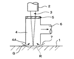
図1について述べると、流体の流れが用いられるDEM概念のガスバージョンは空気である。平たい基板1はレンズ2により合焦または撮像されるレーザビーム3により照射される。レーザビーム3は透明窓5によりその上方端部を閉止されたDEMを通過し、領域Rにおいて基板1をアブレートする。そしてアブレーションプロセスによりつくりだされる引き起こされたデブリDEM4を介してポート6から抜き取られ、DEM4の下方縁4Aと基板1との間の間隙Gを介して吸引される流入空気7に置き換えられる。DEM4とレンズ2はサーボモータ駆動スライド機構(図示せず)に連結された高さセンサーによって基板に対して一定に位置に保持される。
Exemplary embodiments of the present invention will now be described with reference to the accompanying drawings, which are composed of FIGS.
Referring to FIG. 1, the gas version of the DEM concept in which fluid flow is used is air. A
図2について述べると、ガス使用のDEM4はガスを内部に流入せしめるためにDEM4の上方領域にはめ込まれる追加ポート8を具備している。この追加ポート8は窓5の下方側を超えて保持される空気8Aの清掃の流れを準備する。
Referring to FIG. 2, the gas-powered
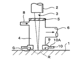
図3について述べると、ガス使用DEM4のより複雑な形態は、間隙Gを所定の高さに維持するために基板1上にパック9を浮揚させる、ポート10を介して空気の流れ10Aが供給される空気パック9に取り付けられる。
Referring to FIG. 3, a more complex form of gas-powered
図4について述べると、空気の流れDEM4はアブレーションサイトRに近接するパック9の内側に追加の空気の流れ11Aを向ける特別のガス流入ポート11を具備している。ポート11はアブレーションサイトRに向かって内側方向に空気の流れ11Aと指向させ、そしていくつかの適切な小さな角度でまたは基板表面にできるだけ平行に空気の流れを指向させるのに役立つ。ポート11はパック9の2つまたはそれ以上の側に構成することができまたはパック9の周りに構成することができる。
Referring to FIG. 4, the
図5について述べると、DEM4′は透明な基板1に使用して好適である。レーザビーム3は、基板1を通過して、レンズ2がその上に位置している側1Bの反対側の基板1の側1A上の領域R′から材料を除去する。この場合、DEM4′はレーザ窓を必要としない。
Referring to FIG. 5, the
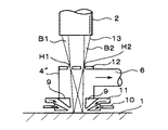
図6について述べると、DEM4′は孔(孔H1,H2により例示される)の配列を有する板12に置き換えられる窓として図1乃至4に記述されるものを図示している。孔の各々はビームレットB1,B2がDEM4′の内側に入りこむことを許可する。板12は上流均質化光学機器により作りだされるビームレット13がフィールドレンズにより焦点スポットの配列に合焦されるレンズ絞りに位置される。これは非望遠中心投射レンズとともに起こる状況である。図6では2つのビームレットB1,B2のみが図示されているが、絞りでのビームレット及び合焦スポットの数は均質化光学機器において用いられるレンズの数に依存して100を超えることもできる。
Referring to FIG. 6, DEM 4 'illustrates what is described in FIGS. 1-4 as a window that is replaced by a
図7について述べると、ガスDEM4は、DEMの壁に堆積されるまたは基板表面に落下するデブリの可能性を最小をするように形成される内的構造を有している。ポート6、6′は内側のポート6、6′のデブリがDEM4に内側に向かって戻らないように下方に傾斜されて構成されている。DEM4の直径は、DEM4の壁から分離される堆積されるデブリを捕まえるよう適切に配置されている適切に噴出するデブリ捕集チャンネル14を有し底部から頂部に向かって次第に増加するようになされている。
Referring to FIG. 7, the
図8について述べると、ガスセル4は、レーザビーム3が水平でありそして基板15が垂直に取り付けられている場合に使用されるエアーパックPに取り付けられている。この場合、基板の後ろ側に取り付けられている第2のエアーパック16はセル4を間隙Gを一定の寸法に維持するよう取り付けられているパックPに基板15を圧接するのに用いられる。
Referring to FIG. 8, the
図9について述べると、この図はパック12と一体化されたDEM11を図示している。DEM11は上方端部14を有する箱13、DEM11を介してレーザビームLが矢印Aの方向に向けられる窓及び基板製品素材17の領域16での開口15を組み入れている。入り口ダクト18、19はパック12中に提供され、レーザビームLが現在除去している領域16の一部分上の領域20にガス(この場合空気)に向かわせることができる。空気の流れはボリューム22に入りそして流出ポート23によりDEMから出るまでダクト21を介して捕捉されたデブリを有する領域20から垂直に移動するようになされる。流入ダクト18、19、領域20、ボリューム22そして流出ポート23の寸法及び割合は利用できる圧力差動分を有する空気の流れが作用し除去されたデブリの量が最適なものとなるのを確実なものとする。この場合、ダクト18及び19は空気の流れを領域20に向かうようにする。しかしながら、これらのダクトのひとつへの流れが逆転して領域20からダクトに沿って流出をなさしめる用意もある。更にダクト18、19に共通の軸に対して直角な軸に沿って流入ダクト18、19と互換性のあるダクト(図示せず)が提供されており、その結果4つの流入ダクトが領域20の周辺に90°の間隔で設けられることとなる。
Referring to FIG. 9, this figure illustrates the
図10について述べると、液体流れDEM4′は基板1に近接する窓5を具備しており、液体17の層は窓5と基板1の上面Uとの間で止められている。窓5はレンズ2を保持する同一の機構に取り付けられている。これらの両方は、センサーとサーボモータ駆動スライド装置により基板表面Uに関してより制御された方法で制御されるようになされ窓5と基板表面U及びレンズ2と基板Uとの間の間隔を一定とする。液体層17はポート18により窓5と基板1との間に間隙Gに入りこみそしてポート19により引き抜かれる。
Referring to FIG. 10, the
1…基板、2…レンズ、3…レーザビーム、4…DEM、4′…DEM,4A…下縁、5…窓、6…流出ポート、7…液体の流れ、8…流入ポート、9…エアーパック、10…ポート、11…特別なガス流入ポート、11A…空気の流れ、12…プレート、13…ビームレット、14…デブリ捕捉チャンネル、15…基板、16…第2のエアーパック、17…基板製品素材、18,19…流入ダクト、20…領域、21…ダクト、22…ボリューム、23…流出ポート、G,G′…間隙、R…領域、R′…領域、B1,B2…ビームレット、H1,H2…孔、U…上面
DESCRIPTION OF
Claims (20)
流体(7)、即ち、ガスまたは蒸気、液体またはこれらの結合体の流れを用いて領域(1)から除去されたデブリを取り除くステップを更に有し、
前記流体(7)は領域上を流れて上述のデブリを取り込み、その後、流体は取り込んだデブリと共に領域から離れるように所定の経路(6)に沿って流れ取り込んだデブリを領域から取り除き、取り込んだデブリが基板上にさらに堆積しないようにすることを特徴とするアブレーション処理方法。 A method of ablation comprising removing a region of the substrate (1) using a laser beam (3),
Further comprising removing debris removed from region (1) using a flow of fluid (7), ie gas or vapor, liquid or combination thereof;
The fluid (7) flows over the region and takes in the above-mentioned debris, and then the fluid flows along the predetermined path (6) so as to leave the region together with the taken-in debris, and removes the taken-in debris from the region. An ablation processing method characterized in that debris is not further deposited on a substrate.
前記レーザビーム(3)用のフォーカスまたは撮像レンズ(2)と前記基板(1)の前記領域との間に位置する部分閉塞デブリ除去モジュール(“DEM”)(4)を有し、
前記DEM(4)は流入ポート(8)と流出ポート(6)を有し、前記領域から除去されたデブリを取り込むために流体(即ち、ガスまたは蒸気、液体またはそれらの複合体)の流れが前記領域(1)上を流れるようにし、その後、取り込んだデブリと共に流体を所定の経路に沿って領域から離すように設けられた手段により取り込んだデブリを前記領域から除去し、取り込んだデブリが基板上にさらに堆積しないようにすることを特徴とする装置。 An apparatus for removing a region of a substrate using a laser,
A partially occluded debris removal module ("DEM") (4) positioned between the focus or imaging lens (2) for the laser beam (3) and the region of the substrate (1);
The DEM (4) has an inflow port (8) and an outflow port (6) so that a flow of fluid (ie, gas or vapor, liquid or complex thereof) can be taken in to remove debris removed from the area. The debris taken in by the means provided to flow over the region (1) and then to move the fluid away from the region along the predetermined path together with the taken-in debris is removed from the region, and the taken-in debris is the substrate An apparatus characterized by preventing further deposition on the top.
Applications Claiming Priority (2)
| Application Number | Priority Date | Filing Date | Title |
|---|---|---|---|
| GB0413029A GB2414954B (en) | 2004-06-11 | 2004-06-11 | Process and apparatus for ablation |
| PCT/GB2005/002326 WO2005120763A2 (en) | 2004-06-11 | 2005-06-13 | Process and apparatus for ablation |
Related Child Applications (1)
| Application Number | Title | Priority Date | Filing Date |
|---|---|---|---|
| JP2012180204A Division JP5389236B2 (en) | 2004-06-11 | 2012-08-15 | Ablation method and apparatus |
Publications (2)
| Publication Number | Publication Date |
|---|---|
| JP2008501531A true JP2008501531A (en) | 2008-01-24 |
| JP2008501531A5 JP2008501531A5 (en) | 2008-07-31 |
Family
ID=32732303
Family Applications (2)
| Application Number | Title | Priority Date | Filing Date |
|---|---|---|---|
| JP2007520873A Pending JP2008501531A (en) | 2004-06-11 | 2005-06-13 | Ablation method and apparatus |
| JP2012180204A Expired - Fee Related JP5389236B2 (en) | 2004-06-11 | 2012-08-15 | Ablation method and apparatus |
Family Applications After (1)
| Application Number | Title | Priority Date | Filing Date |
|---|---|---|---|
| JP2012180204A Expired - Fee Related JP5389236B2 (en) | 2004-06-11 | 2012-08-15 | Ablation method and apparatus |
Country Status (6)
| Country | Link |
|---|---|
| US (2) | US8344285B2 (en) |
| JP (2) | JP2008501531A (en) |
| KR (1) | KR100890295B1 (en) |
| CN (1) | CN101018639B (en) |
| GB (1) | GB2414954B (en) |
| WO (1) | WO2005120763A2 (en) |
Cited By (10)
| Publication number | Priority date | Publication date | Assignee | Title |
|---|---|---|---|---|
| WO2009155202A2 (en) * | 2008-06-18 | 2009-12-23 | Electro Scientific Industries, Inc | Debris capture and removal for laser micromachining |
| JP2010000500A (en) * | 2008-06-23 | 2010-01-07 | Commiss Energ Atom | Method of eliminating engraving defect from metallic film deposited on flexible carrier |
| JP2011125871A (en) * | 2009-12-15 | 2011-06-30 | Disco Abrasive Syst Ltd | Laser beam machining apparatus |
| JP2011251322A (en) * | 2010-06-03 | 2011-12-15 | Disco Corp | Laser machining device |
| JP2012101230A (en) * | 2010-11-08 | 2012-05-31 | Disco Corp | Laser beam machining device |
| JP2013252532A (en) * | 2012-06-06 | 2013-12-19 | Disco Corp | Laser beam machining apparatus |
| JP2014024117A (en) * | 2012-07-26 | 2014-02-06 | Electro Scientific Industries Inc | Material collection method and material collection apparatus |
| JP2015134364A (en) * | 2014-01-16 | 2015-07-27 | 株式会社デンソー | Laser processing apparatus and laser processing method |
| JP2019076911A (en) * | 2017-10-20 | 2019-05-23 | 株式会社Ihi | Laser welding device and laser welding method |
| US10847759B2 (en) | 2018-12-10 | 2020-11-24 | Samsung Display Co., Ltd. | Method of manufacturing display apparatus |
Families Citing this family (53)
| Publication number | Priority date | Publication date | Assignee | Title |
|---|---|---|---|---|
| US20050064137A1 (en) * | 2003-01-29 | 2005-03-24 | Hunt Alan J. | Method for forming nanoscale features and structures produced thereby |
| EP1657020A1 (en) * | 2004-11-10 | 2006-05-17 | Synova S.A. | Process and device for optimising the coherence of a fluidjet used for materialworking and fluid flow nozzle for such a device |
| CN100536046C (en) * | 2005-02-25 | 2009-09-02 | 京瓷株式会社 | Method for machining compound crude piece |
| US7863542B2 (en) | 2005-12-22 | 2011-01-04 | Sony Corporation | Laser processing apparatus and laser processing method as well as debris extraction mechanism and debris extraction method |
| GB2438527B (en) * | 2006-03-07 | 2008-04-23 | Sony Corp | Laser processing apparatus, laser processing head and laser processing method |
| JP5165203B2 (en) * | 2006-03-07 | 2013-03-21 | ソニー株式会社 | Laser processing apparatus and laser processing method |
| SE530592C2 (en) * | 2007-01-16 | 2008-07-15 | Tetra Laval Holdings & Finance | Apparatus for laser processing of a packaging material web |
| CN101518854B (en) * | 2008-02-29 | 2011-08-31 | 深圳市大族激光科技股份有限公司 | Dust suction protection device of lens |
| JP5094535B2 (en) * | 2008-05-07 | 2012-12-12 | 富士フイルム株式会社 | Recess formation method, uneven product manufacturing method, light emitting element manufacturing method, and optical element manufacturing method |
| US8288678B2 (en) * | 2008-12-18 | 2012-10-16 | Ppg Industries Ohio, Inc. | Device for and method of maintaining a constant distance between a cutting edge and a reference surface |
| FR2940154B1 (en) * | 2008-12-23 | 2011-02-25 | Commissariat Energie Atomique | FINE PARTICLE SUCTION AVALATOR AND DEVICE FOR LASER ABLATION OF A SURFACE LAYER OF A WALL COMPRISING SUCH AN AVALER |
| KR101135499B1 (en) * | 2010-05-28 | 2012-04-13 | 삼성에스디아이 주식회사 | Laser cleaning device of electrode tab for battery and laser cleaning method using the same |
| GB2481190B (en) * | 2010-06-04 | 2015-01-14 | Plastic Logic Ltd | Laser ablation |
| KR101256430B1 (en) * | 2011-03-15 | 2013-04-18 | 삼성에스디아이 주식회사 | Laser welding apparatus |
| DE102011001322A1 (en) * | 2011-03-16 | 2012-09-20 | Ipg Laser Gmbh | Machine and method for material processing of workpieces with a laser beam |
| DE102011107982A1 (en) * | 2011-07-20 | 2013-01-24 | Rena Gmbh | Tool head (LCP head) |
| WO2013029038A2 (en) | 2011-08-25 | 2013-02-28 | Preco, Inc. | Method and apparatus for making a clean cut with a laser |
| DE102012202330B4 (en) * | 2012-02-16 | 2017-08-17 | Trumpf Laser Gmbh | Laser processing apparatus with a laser processing head movable relative to a clamping claw |
| CN102642085A (en) * | 2012-04-01 | 2012-08-22 | 上海交通大学 | Plasma-side-suction negative pressure device for laser welding |
| CN102692447B (en) * | 2012-06-11 | 2014-04-02 | 燕山大学 | Miniaturized high pulse single-rail discharging ablation device |
| JP5663776B1 (en) * | 2014-03-27 | 2015-02-04 | 福井県 | Suction method, suction device, laser processing method, and laser processing device |
| EP2944413A1 (en) * | 2014-05-12 | 2015-11-18 | Boegli-Gravures S.A. | Device for mask projection of femtosecond and picosecond laser beams with a blade, a mask and lenses' systems |
| CN111496379B (en) * | 2014-08-19 | 2022-08-26 | 亮锐控股有限公司 | Sapphire collector for reducing mechanical damage sustained during die-level laser lift-off |
| CN105458495B (en) * | 2014-09-11 | 2017-03-22 | 大族激光科技产业集团股份有限公司 | Matched system used for laser precise machining |
| GB2530982B (en) * | 2014-09-30 | 2018-10-24 | M Solv Ltd | Bernoulli process head |
| US10335899B2 (en) * | 2014-10-31 | 2019-07-02 | Prima Power Laserdyne | Cross jet laser welding nozzle |
| CN104625404B (en) * | 2014-12-12 | 2016-08-17 | 南通富士通微电子股份有限公司 | A kind of cleaning plant in laser marking technique |
| CN105772942B (en) * | 2014-12-25 | 2018-07-03 | 大族激光科技产业集团股份有限公司 | A kind of coaxial air blowing protector of laser welded seam and application process |
| KR102572643B1 (en) * | 2015-05-13 | 2023-08-31 | 루미리즈 홀딩 비.브이. | Sapphire collector to reduce mechanical damage during die-level laser lift-off |
| US10328529B2 (en) | 2015-08-26 | 2019-06-25 | Electro Scientific Industries, Inc | Laser scan sequencing and direction with respect to gas flow |
| EP3167998B1 (en) * | 2015-11-16 | 2021-01-06 | Preco, Inc. | Galvo cooling air bypass to reduce contamination |
| CN105499804B (en) * | 2016-01-18 | 2018-01-02 | 华中科技大学 | The control method and control device of weld seam inner void in a kind of laser beam welding |
| KR101739839B1 (en) * | 2016-02-02 | 2017-05-25 | 한동대학교 산학협력단 | Beam Homogenizer for Surface Modification |
| JP6999264B2 (en) * | 2016-08-04 | 2022-01-18 | 株式会社日本製鋼所 | Laser peeling device, laser peeling method, and manufacturing method of organic EL display |
| CN108098155B (en) * | 2016-11-17 | 2020-10-09 | 宁德新能源科技有限公司 | Dust removing device |
| JP6450783B2 (en) * | 2017-01-19 | 2019-01-09 | ファナック株式会社 | Nozzle for laser processing head |
| JP6450784B2 (en) * | 2017-01-19 | 2019-01-09 | ファナック株式会社 | Laser processing machine |
| KR101876963B1 (en) * | 2017-03-14 | 2018-07-10 | 주식회사 에이치비테크놀러지 | Thin film forming apparatus |
| KR101876961B1 (en) * | 2017-03-14 | 2018-07-10 | 주식회사 에이치비테크놀러지 | Thin film forming apparatus |
| JP6508549B2 (en) * | 2017-05-12 | 2019-05-08 | パナソニックIpマネジメント株式会社 | Laser processing equipment |
| KR20190110442A (en) * | 2018-03-20 | 2019-09-30 | 오르보테크 엘티디. | System for removal of debris from a substrate in an optical processing system |
| WO2020003421A1 (en) | 2018-06-27 | 2020-01-02 | ギガフォトン株式会社 | Laser machining device, laser machining system, and laser machining method |
| JP6852031B2 (en) * | 2018-09-26 | 2021-03-31 | 株式会社東芝 | Welding equipment and nozzle equipment |
| CN109623140B (en) * | 2018-12-11 | 2021-07-27 | 中国科学院宁波材料技术与工程研究所 | Optical fiber and water-guide laser coupling processing device and system |
| KR20200093724A (en) * | 2019-01-28 | 2020-08-06 | 삼성디스플레이 주식회사 | Suction deivice and panel processing apparatus including the same |
| US11273520B2 (en) | 2019-01-31 | 2022-03-15 | General Electric Company | System and method for automated laser ablation |
| DE102019103659B4 (en) * | 2019-02-13 | 2023-11-30 | Bystronic Laser Ag | Gas guide, laser cutting head and laser cutting machine |
| GB2581378A (en) * | 2019-02-15 | 2020-08-19 | Hanbury Robert | Laser cutting sheet/material support system |
| JP7306860B2 (en) * | 2019-04-11 | 2023-07-11 | Jswアクティナシステム株式会社 | Laser processing equipment |
| US11267075B2 (en) * | 2019-05-16 | 2022-03-08 | Raytheon Technologies Corporation | By-product removal device for laser welding |
| JP7081050B2 (en) * | 2019-06-28 | 2022-06-06 | 三菱重工業株式会社 | Laser processing equipment |
| CN112620255B (en) * | 2020-12-15 | 2022-05-03 | 哈尔滨工业大学(深圳) | Underwater laser water flow composite cleaning system and method |
| CN114378446B (en) * | 2022-03-22 | 2022-07-29 | 苏州密尔光子科技有限公司 | Laser processing auxiliary device, method and laser equipment with device |
Citations (5)
| Publication number | Priority date | Publication date | Assignee | Title |
|---|---|---|---|---|
| JPH09141484A (en) * | 1995-11-22 | 1997-06-03 | Nikon Corp | Laser beam machine |
| JPH09206975A (en) * | 1996-01-30 | 1997-08-12 | Mitsubishi Electric Corp | Laser beam machining method and device therefor |
| JPH09277071A (en) * | 1996-04-18 | 1997-10-28 | Nisshinbo Ind Inc | Method and device for laser beam machining |
| JP2002210582A (en) * | 2001-01-19 | 2002-07-30 | Ricoh Microelectronics Co Ltd | Beam-machining device |
| JP2003245791A (en) * | 2002-02-25 | 2003-09-02 | Sony Corp | Laser beam machining device and laser beam machining method |
Family Cites Families (22)
| Publication number | Priority date | Publication date | Assignee | Title |
|---|---|---|---|---|
| FR2627409A1 (en) * | 1988-02-24 | 1989-08-25 | Lectra Systemes Sa | LASER CUTTING APPARATUS WITH A FUME EXHAUST DEVICE |
| DE3923829A1 (en) * | 1989-07-19 | 1991-01-31 | Fraunhofer Ges Forschung | Suction extraction hood for laser cutting and sputtering unit - has inclined nozzles to direct curtain of gas to focus of laser beam and esp. neutralise and remove dangerous reaction products |
| US5359176A (en) * | 1993-04-02 | 1994-10-25 | International Business Machines Corporation | Optics and environmental protection device for laser processing applications |
| NZ272635A (en) * | 1994-08-02 | 1998-02-26 | Mcneil Ppc Inc | Laser cutting/drilling processing head that creates a vortex gas flow within the head to clean and prevent back spatting of particles onto the lens therein |
| JP3203294B2 (en) * | 1994-09-30 | 2001-08-27 | 三菱電機株式会社 | Lens cover for laser processing equipment |
| GB9507719D0 (en) * | 1995-04-13 | 1995-05-31 | Boc Group Plc | Machining of materials |
| US5922225A (en) * | 1996-03-06 | 1999-07-13 | Blake; Ronald J. | Apparatus for reducing vaporized material deposits during laser cutting |
| US6064035A (en) * | 1997-12-30 | 2000-05-16 | Lsp Technologies, Inc. | Process chamber for laser peening |
| US6262390B1 (en) * | 1998-12-14 | 2001-07-17 | International Business Machines Corporation | Repair process for aluminum nitride substrates |
| US6359257B1 (en) * | 1999-02-19 | 2002-03-19 | Lsp Technologies, Inc. | Beam path clearing for laser peening |
| US6342687B1 (en) | 2000-02-17 | 2002-01-29 | Universal Laser Systems, Inc. | Portable laser system with portable or stationary fume evacuation |
| EP1149660A1 (en) * | 2000-04-03 | 2001-10-31 | Rexam Beverage Packaging AB | Method and device for dust protection in a laser processing apparatus |
| JP2001321979A (en) * | 2000-05-12 | 2001-11-20 | Matsushita Electric Ind Co Ltd | Machining dust collecting device for laser beam hole machining device |
| JP3479833B2 (en) * | 2000-08-22 | 2003-12-15 | 日本電気株式会社 | Laser correction method and apparatus |
| US6580053B1 (en) * | 2000-08-31 | 2003-06-17 | Sharp Laboratories Of America, Inc. | Apparatus to control the amount of oxygen incorporated into polycrystalline silicon film during excimer laser processing of silicon films |
| DE10123097B8 (en) | 2001-05-07 | 2006-05-04 | Jenoptik Automatisierungstechnik Gmbh | Tool head for laser material processing |
| US6635844B2 (en) * | 2002-01-03 | 2003-10-21 | United Microelectronics Corp. | Apparatus for on-line cleaning a wafer chuck with laser |
| JP4459514B2 (en) * | 2002-09-05 | 2010-04-28 | 株式会社半導体エネルギー研究所 | Laser marking device |
| JP2004160463A (en) * | 2002-11-11 | 2004-06-10 | Hyogo Prefecture | Laser processing apparatus and machining method for workpiece using the same |
| GB2400063B (en) * | 2003-04-03 | 2006-02-15 | Exitech Ltd | Positioning method and apparatus and a product thereof |
| JP4205486B2 (en) * | 2003-05-16 | 2009-01-07 | 株式会社ディスコ | Laser processing equipment |
| JP4404085B2 (en) * | 2006-11-02 | 2010-01-27 | ソニー株式会社 | Laser processing apparatus, laser processing head, and laser processing method |
-
2004
- 2004-06-11 GB GB0413029A patent/GB2414954B/en not_active Expired - Fee Related
-
2005
- 2005-06-13 WO PCT/GB2005/002326 patent/WO2005120763A2/en active Application Filing
- 2005-06-13 CN CN2005800265196A patent/CN101018639B/en not_active Expired - Fee Related
- 2005-06-13 KR KR1020067026294A patent/KR100890295B1/en not_active IP Right Cessation
- 2005-06-13 JP JP2007520873A patent/JP2008501531A/en active Pending
- 2005-06-13 US US11/628,911 patent/US8344285B2/en not_active Expired - Fee Related
-
2012
- 2012-08-15 JP JP2012180204A patent/JP5389236B2/en not_active Expired - Fee Related
- 2012-12-19 US US13/720,009 patent/US8809732B2/en not_active Expired - Fee Related
Patent Citations (5)
| Publication number | Priority date | Publication date | Assignee | Title |
|---|---|---|---|---|
| JPH09141484A (en) * | 1995-11-22 | 1997-06-03 | Nikon Corp | Laser beam machine |
| JPH09206975A (en) * | 1996-01-30 | 1997-08-12 | Mitsubishi Electric Corp | Laser beam machining method and device therefor |
| JPH09277071A (en) * | 1996-04-18 | 1997-10-28 | Nisshinbo Ind Inc | Method and device for laser beam machining |
| JP2002210582A (en) * | 2001-01-19 | 2002-07-30 | Ricoh Microelectronics Co Ltd | Beam-machining device |
| JP2003245791A (en) * | 2002-02-25 | 2003-09-02 | Sony Corp | Laser beam machining device and laser beam machining method |
Cited By (12)
| Publication number | Priority date | Publication date | Assignee | Title |
|---|---|---|---|---|
| WO2009155202A2 (en) * | 2008-06-18 | 2009-12-23 | Electro Scientific Industries, Inc | Debris capture and removal for laser micromachining |
| WO2009155202A3 (en) * | 2008-06-18 | 2010-05-06 | Electro Scientific Industries, Inc | Debris capture and removal for laser micromachining |
| US8207472B2 (en) | 2008-06-18 | 2012-06-26 | Electro Scientific Industries, Inc. | Debris capture and removal for laser micromachining |
| JP2010000500A (en) * | 2008-06-23 | 2010-01-07 | Commiss Energ Atom | Method of eliminating engraving defect from metallic film deposited on flexible carrier |
| JP2011125871A (en) * | 2009-12-15 | 2011-06-30 | Disco Abrasive Syst Ltd | Laser beam machining apparatus |
| JP2011251322A (en) * | 2010-06-03 | 2011-12-15 | Disco Corp | Laser machining device |
| JP2012101230A (en) * | 2010-11-08 | 2012-05-31 | Disco Corp | Laser beam machining device |
| JP2013252532A (en) * | 2012-06-06 | 2013-12-19 | Disco Corp | Laser beam machining apparatus |
| JP2014024117A (en) * | 2012-07-26 | 2014-02-06 | Electro Scientific Industries Inc | Material collection method and material collection apparatus |
| JP2015134364A (en) * | 2014-01-16 | 2015-07-27 | 株式会社デンソー | Laser processing apparatus and laser processing method |
| JP2019076911A (en) * | 2017-10-20 | 2019-05-23 | 株式会社Ihi | Laser welding device and laser welding method |
| US10847759B2 (en) | 2018-12-10 | 2020-11-24 | Samsung Display Co., Ltd. | Method of manufacturing display apparatus |
Also Published As
| Publication number | Publication date |
|---|---|
| GB2414954B (en) | 2008-02-06 |
| JP2012254482A (en) | 2012-12-27 |
| US8344285B2 (en) | 2013-01-01 |
| US8809732B2 (en) | 2014-08-19 |
| CN101018639A (en) | 2007-08-15 |
| US20130140287A1 (en) | 2013-06-06 |
| WO2005120763A2 (en) | 2005-12-22 |
| CN101018639B (en) | 2010-04-21 |
| GB2414954A (en) | 2005-12-14 |
| US20080041832A1 (en) | 2008-02-21 |
| WO2005120763A3 (en) | 2006-02-23 |
| KR20070039493A (en) | 2007-04-12 |
| KR100890295B1 (en) | 2009-03-26 |
| JP5389236B2 (en) | 2014-01-15 |
| GB0413029D0 (en) | 2004-07-14 |
Similar Documents
| Publication | Publication Date | Title |
|---|---|---|
| JP5389236B2 (en) | Ablation method and apparatus | |
| TWI374070B (en) | Laser processing apparatus and laser processing method as well as debris extraction mechanism and debris extraction method | |
| JP4404085B2 (en) | Laser processing apparatus, laser processing head, and laser processing method | |
| KR101299039B1 (en) | Laser processing apparatus, laser processing head and laser processing method | |
| CN1212643C (en) | Cleaning device of on-line laser wafer bearing | |
| JP4848003B2 (en) | Immersion lithography system with tilted showerhead and immersion lithography method | |
| TWI778159B (en) | Laser processing equipment | |
| JP2022189840A (en) | Photomask pellicle glue residue removal | |
| KR20080075613A (en) | Treatment method of processing residue and origination gas by laser processing and treatment apparatus | |
| JP3932930B2 (en) | Laser processing apparatus and laser processing method | |
| TWI801596B (en) | Laser processing device | |
| TWI303591B (en) | Process and apparatus for ablation | |
| JP2003303799A (en) | Surface-cleaning equipment and surface-cleaning method | |
| JP4185016B2 (en) | Dust collection method and apparatus for laser processing by-products, and laser processing apparatus | |
| JP2003303800A (en) | Surface-cleaning equipment and surface-cleaning method | |
| US20210063890A1 (en) | Lithography exposure method with debris removing mechanism | |
| CN109530930B (en) | Method for processing chip by laser | |
| US8585824B2 (en) | Method of ablating a surface layer of a wall, and associated device | |
| GB2438527A (en) | Laser processing apparatus,laser processing head and laser processing method |
Legal Events
| Date | Code | Title | Description |
|---|---|---|---|
| A521 | Request for written amendment filed |
Free format text: JAPANESE INTERMEDIATE CODE: A523 Effective date: 20080611 |
|
| A621 | Written request for application examination |
Free format text: JAPANESE INTERMEDIATE CODE: A621 Effective date: 20080611 |
|
| A131 | Notification of reasons for refusal |
Free format text: JAPANESE INTERMEDIATE CODE: A131 Effective date: 20110524 |
|
| A521 | Request for written amendment filed |
Free format text: JAPANESE INTERMEDIATE CODE: A523 Effective date: 20110719 |
|
| A131 | Notification of reasons for refusal |
Free format text: JAPANESE INTERMEDIATE CODE: A131 Effective date: 20110823 |
|
| A521 | Request for written amendment filed |
Free format text: JAPANESE INTERMEDIATE CODE: A523 Effective date: 20111011 |
|
| A02 | Decision of refusal |
Free format text: JAPANESE INTERMEDIATE CODE: A02 Effective date: 20120417 |