EP2944413A1 - Device for mask projection of femtosecond and picosecond laser beams with a blade, a mask and lenses' systems - Google Patents
Device for mask projection of femtosecond and picosecond laser beams with a blade, a mask and lenses' systems Download PDFInfo
- Publication number
- EP2944413A1 EP2944413A1 EP14167931.6A EP14167931A EP2944413A1 EP 2944413 A1 EP2944413 A1 EP 2944413A1 EP 14167931 A EP14167931 A EP 14167931A EP 2944413 A1 EP2944413 A1 EP 2944413A1
- Authority
- EP
- European Patent Office
- Prior art keywords
- laser beam
- mask
- imaging
- laser
- lens system
- Prior art date
- Legal status (The legal status is an assumption and is not a legal conclusion. Google has not performed a legal analysis and makes no representation as to the accuracy of the status listed.)
- Withdrawn
Links
- 238000003384 imaging method Methods 0.000 claims abstract description 64
- 239000000758 substrate Substances 0.000 claims abstract description 47
- 230000003287 optical effect Effects 0.000 claims abstract description 29
- 230000005855 radiation Effects 0.000 claims description 11
- 239000003638 chemical reducing agent Substances 0.000 claims description 7
- 238000000034 method Methods 0.000 description 17
- 239000000463 material Substances 0.000 description 14
- 210000002381 plasma Anatomy 0.000 description 10
- 238000007493 shaping process Methods 0.000 description 10
- 230000005540 biological transmission Effects 0.000 description 6
- 230000001681 protective effect Effects 0.000 description 5
- 230000009467 reduction Effects 0.000 description 5
- 238000012545 processing Methods 0.000 description 4
- 238000013507 mapping Methods 0.000 description 3
- 238000002679 ablation Methods 0.000 description 2
- 230000004075 alteration Effects 0.000 description 2
- 238000004364 calculation method Methods 0.000 description 2
- 239000003795 chemical substances by application Substances 0.000 description 2
- 238000013461 design Methods 0.000 description 2
- 238000005516 engineering process Methods 0.000 description 2
- 238000004519 manufacturing process Methods 0.000 description 2
- 239000007769 metal material Substances 0.000 description 2
- 238000011160 research Methods 0.000 description 2
- 238000000926 separation method Methods 0.000 description 2
- 239000007787 solid Substances 0.000 description 2
- 125000006850 spacer group Chemical group 0.000 description 2
- 230000003746 surface roughness Effects 0.000 description 2
- VYPSYNLAJGMNEJ-UHFFFAOYSA-N Silicium dioxide Chemical compound O=[Si]=O VYPSYNLAJGMNEJ-UHFFFAOYSA-N 0.000 description 1
- 238000010521 absorption reaction Methods 0.000 description 1
- 238000009412 basement excavation Methods 0.000 description 1
- 230000015572 biosynthetic process Effects 0.000 description 1
- 238000011109 contamination Methods 0.000 description 1
- 230000003247 decreasing effect Effects 0.000 description 1
- 230000001419 dependent effect Effects 0.000 description 1
- 230000008021 deposition Effects 0.000 description 1
- 230000000694 effects Effects 0.000 description 1
- 238000002474 experimental method Methods 0.000 description 1
- 239000005350 fused silica glass Substances 0.000 description 1
- 238000000265 homogenisation Methods 0.000 description 1
- 230000010354 integration Effects 0.000 description 1
- 238000000608 laser ablation Methods 0.000 description 1
- SYHGEUNFJIGTRX-UHFFFAOYSA-N methylenedioxypyrovalerone Chemical compound C=1C=C2OCOC2=CC=1C(=O)C(CCC)N1CCCC1 SYHGEUNFJIGTRX-UHFFFAOYSA-N 0.000 description 1
- 238000012986 modification Methods 0.000 description 1
- 230000004048 modification Effects 0.000 description 1
- 239000011368 organic material Substances 0.000 description 1
- 230000008569 process Effects 0.000 description 1
- 235000019592 roughness Nutrition 0.000 description 1
- 230000035939 shock Effects 0.000 description 1
- 238000004088 simulation Methods 0.000 description 1
- 230000002123 temporal effect Effects 0.000 description 1
- 239000010409 thin film Substances 0.000 description 1
Images


Classifications
-
- B—PERFORMING OPERATIONS; TRANSPORTING
- B23—MACHINE TOOLS; METAL-WORKING NOT OTHERWISE PROVIDED FOR
- B23K—SOLDERING OR UNSOLDERING; WELDING; CLADDING OR PLATING BY SOLDERING OR WELDING; CUTTING BY APPLYING HEAT LOCALLY, e.g. FLAME CUTTING; WORKING BY LASER BEAM
- B23K26/00—Working by laser beam, e.g. welding, cutting or boring
- B23K26/02—Positioning or observing the workpiece, e.g. with respect to the point of impact; Aligning, aiming or focusing the laser beam
- B23K26/06—Shaping the laser beam, e.g. by masks or multi-focusing
- B23K26/064—Shaping the laser beam, e.g. by masks or multi-focusing by means of optical elements, e.g. lenses, mirrors or prisms
- B23K26/066—Shaping the laser beam, e.g. by masks or multi-focusing by means of optical elements, e.g. lenses, mirrors or prisms by using masks
-
- B—PERFORMING OPERATIONS; TRANSPORTING
- B23—MACHINE TOOLS; METAL-WORKING NOT OTHERWISE PROVIDED FOR
- B23K—SOLDERING OR UNSOLDERING; WELDING; CLADDING OR PLATING BY SOLDERING OR WELDING; CUTTING BY APPLYING HEAT LOCALLY, e.g. FLAME CUTTING; WORKING BY LASER BEAM
- B23K26/00—Working by laser beam, e.g. welding, cutting or boring
- B23K26/02—Positioning or observing the workpiece, e.g. with respect to the point of impact; Aligning, aiming or focusing the laser beam
- B23K26/04—Automatically aligning, aiming or focusing the laser beam, e.g. using the back-scattered light
- B23K26/046—Automatically focusing the laser beam
-
- B—PERFORMING OPERATIONS; TRANSPORTING
- B23—MACHINE TOOLS; METAL-WORKING NOT OTHERWISE PROVIDED FOR
- B23K—SOLDERING OR UNSOLDERING; WELDING; CLADDING OR PLATING BY SOLDERING OR WELDING; CUTTING BY APPLYING HEAT LOCALLY, e.g. FLAME CUTTING; WORKING BY LASER BEAM
- B23K26/00—Working by laser beam, e.g. welding, cutting or boring
- B23K26/02—Positioning or observing the workpiece, e.g. with respect to the point of impact; Aligning, aiming or focusing the laser beam
- B23K26/06—Shaping the laser beam, e.g. by masks or multi-focusing
- B23K26/062—Shaping the laser beam, e.g. by masks or multi-focusing by direct control of the laser beam
- B23K26/0622—Shaping the laser beam, e.g. by masks or multi-focusing by direct control of the laser beam by shaping pulses
- B23K26/0624—Shaping the laser beam, e.g. by masks or multi-focusing by direct control of the laser beam by shaping pulses using ultrashort pulses, i.e. pulses of 1ns or less
-
- B—PERFORMING OPERATIONS; TRANSPORTING
- B23—MACHINE TOOLS; METAL-WORKING NOT OTHERWISE PROVIDED FOR
- B23K—SOLDERING OR UNSOLDERING; WELDING; CLADDING OR PLATING BY SOLDERING OR WELDING; CUTTING BY APPLYING HEAT LOCALLY, e.g. FLAME CUTTING; WORKING BY LASER BEAM
- B23K26/00—Working by laser beam, e.g. welding, cutting or boring
- B23K26/02—Positioning or observing the workpiece, e.g. with respect to the point of impact; Aligning, aiming or focusing the laser beam
- B23K26/06—Shaping the laser beam, e.g. by masks or multi-focusing
- B23K26/064—Shaping the laser beam, e.g. by masks or multi-focusing by means of optical elements, e.g. lenses, mirrors or prisms
- B23K26/0643—Shaping the laser beam, e.g. by masks or multi-focusing by means of optical elements, e.g. lenses, mirrors or prisms comprising mirrors
-
- B—PERFORMING OPERATIONS; TRANSPORTING
- B23—MACHINE TOOLS; METAL-WORKING NOT OTHERWISE PROVIDED FOR
- B23K—SOLDERING OR UNSOLDERING; WELDING; CLADDING OR PLATING BY SOLDERING OR WELDING; CUTTING BY APPLYING HEAT LOCALLY, e.g. FLAME CUTTING; WORKING BY LASER BEAM
- B23K26/00—Working by laser beam, e.g. welding, cutting or boring
- B23K26/02—Positioning or observing the workpiece, e.g. with respect to the point of impact; Aligning, aiming or focusing the laser beam
- B23K26/06—Shaping the laser beam, e.g. by masks or multi-focusing
- B23K26/064—Shaping the laser beam, e.g. by masks or multi-focusing by means of optical elements, e.g. lenses, mirrors or prisms
- B23K26/0648—Shaping the laser beam, e.g. by masks or multi-focusing by means of optical elements, e.g. lenses, mirrors or prisms comprising lenses
-
- B—PERFORMING OPERATIONS; TRANSPORTING
- B23—MACHINE TOOLS; METAL-WORKING NOT OTHERWISE PROVIDED FOR
- B23K—SOLDERING OR UNSOLDERING; WELDING; CLADDING OR PLATING BY SOLDERING OR WELDING; CUTTING BY APPLYING HEAT LOCALLY, e.g. FLAME CUTTING; WORKING BY LASER BEAM
- B23K26/00—Working by laser beam, e.g. welding, cutting or boring
- B23K26/12—Working by laser beam, e.g. welding, cutting or boring in a special atmosphere, e.g. in an enclosure
- B23K26/1224—Working by laser beam, e.g. welding, cutting or boring in a special atmosphere, e.g. in an enclosure in vacuum
-
- B—PERFORMING OPERATIONS; TRANSPORTING
- B23—MACHINE TOOLS; METAL-WORKING NOT OTHERWISE PROVIDED FOR
- B23K—SOLDERING OR UNSOLDERING; WELDING; CLADDING OR PLATING BY SOLDERING OR WELDING; CUTTING BY APPLYING HEAT LOCALLY, e.g. FLAME CUTTING; WORKING BY LASER BEAM
- B23K26/00—Working by laser beam, e.g. welding, cutting or boring
- B23K26/12—Working by laser beam, e.g. welding, cutting or boring in a special atmosphere, e.g. in an enclosure
- B23K26/127—Working by laser beam, e.g. welding, cutting or boring in a special atmosphere, e.g. in an enclosure in an enclosure
-
- B—PERFORMING OPERATIONS; TRANSPORTING
- B23—MACHINE TOOLS; METAL-WORKING NOT OTHERWISE PROVIDED FOR
- B23K—SOLDERING OR UNSOLDERING; WELDING; CLADDING OR PLATING BY SOLDERING OR WELDING; CUTTING BY APPLYING HEAT LOCALLY, e.g. FLAME CUTTING; WORKING BY LASER BEAM
- B23K26/00—Working by laser beam, e.g. welding, cutting or boring
- B23K26/14—Working by laser beam, e.g. welding, cutting or boring using a fluid stream, e.g. a jet of gas, in conjunction with the laser beam; Nozzles therefor
- B23K26/1462—Nozzles; Features related to nozzles
-
- B—PERFORMING OPERATIONS; TRANSPORTING
- B23—MACHINE TOOLS; METAL-WORKING NOT OTHERWISE PROVIDED FOR
- B23K—SOLDERING OR UNSOLDERING; WELDING; CLADDING OR PLATING BY SOLDERING OR WELDING; CUTTING BY APPLYING HEAT LOCALLY, e.g. FLAME CUTTING; WORKING BY LASER BEAM
- B23K26/00—Working by laser beam, e.g. welding, cutting or boring
- B23K26/16—Removal of by-products, e.g. particles or vapours produced during treatment of a workpiece
-
- B—PERFORMING OPERATIONS; TRANSPORTING
- B23—MACHINE TOOLS; METAL-WORKING NOT OTHERWISE PROVIDED FOR
- B23K—SOLDERING OR UNSOLDERING; WELDING; CLADDING OR PLATING BY SOLDERING OR WELDING; CUTTING BY APPLYING HEAT LOCALLY, e.g. FLAME CUTTING; WORKING BY LASER BEAM
- B23K26/00—Working by laser beam, e.g. welding, cutting or boring
- B23K26/352—Working by laser beam, e.g. welding, cutting or boring for surface treatment
Definitions
- the invention relates to a device for mask projection of femtosecond and picosecond laser beams.
- the laser beam emitted from an excimer laser having a wavelength of 157 nm, 193 nm, 248 nm, 308 nm or 351 nm has a nearly rectangular cross section, an inhomogeneous intensity distribution across the laser beam cross section and a short coherence length Therefore, without further beam shaping can not be used for microstructuring, by means of a homogenizer, which decomposes the laser beam into a predetermined number of sub-beams and these preferably superimposed again, and a field lens to a laser beam with a predetermined square laser beam cross-section with a homogeneous intensity distribution (top flat intensity profile) so-called homogeneous spot formed at the location P in beam propagation direction.
- a mask having a predetermined geometry of the transmissive mask area areas is positioned.
- the intensity profile required for the microstructure to be generated over the laser beam cross section eg a lattice-shaped intensity profile, is formed from the homogeneous intensity distribution of the laser beam in the homogeneous spot and determined by means of a focusing optical system suitable for the excimer laser wavelength with a predetermined reduction imaging ratio on the imaged to be structured substrate.
- the geometric shape of the transmitting surface or the opening of a diaphragm which is arranged at a short distance before or after the mask or preferably in contact with this, thereby generates the cross-sectional geometry (outline shape) of the through Mask shaped intensity profile of the laser beam (see, for example, publications WO2010111798 and EP 2 336 823 A1 ).
- the minimum feature dimensions achievable by the excimer laser mask projection method are in the range of a few microns.
- Femtosecond lasers fs lasers
- picosecond lasers ps lasers
- fs lasers emit laser beams with central wavelengths predominantly in the range of 775 nm to 1064 nm, with an almost Gaussian intensity distribution over the laser beam cross section and with a much greater coherence length than the excimer lasers.
- These fs and ps laser beams are shaped by means of commercially available focusing optics into beams with a low focus cross section and used, for example, for the microstructuring of solid surfaces.
- the intensity distribution over the focus cross section of the laser beam is also Gaussian and not homogeneous; At the location of the Gaussian radius, the intensity is only 1 / e - fold, ie 36.8%, and at the location of the beam radius only 1 / e 2 times, ie 13.5%, of the value in the beam center.
- beam homogenizers have been developed, which are arranged between the laser output and the focusing optics.
- beam homogenizers for fs and ps laser beams see, eg A. Laskin and V.
- the focal radius of the Gaussian distributed laser beam is a function of the wavelength, the radius of the raw beam emitted by the laser and the focus distance and can not be arbitrarily reduced.
- a FS-150-10 fs laser microstructuring unit from 3D-Micromac AG Chemnitz with a CPA 2010 laser from Clark Inc., USA, with 775 nm central wavelength and 1 mJ (1 millijoule) pulse energy and 150 fs Pulse duration, for example, the smallest Gaussian focus radius is 5.7 microns with a lens with 32 mm focal length, despite 2-fold beam expansion of 3 mm Gaussian radius to 6 mm and homogenization.
- the achievable focus radii of a few microns are too large for a variety of applications in the field of micro- and nanostructuring, structural dimensions of a few micrometers ( ⁇ m) and below are not achievable.
- the edge sharpness of the microstructures produced by means of the focus method with dimensions of up to a few tens of micrometers is too low, for example even with pulse overlapping of the laser beam.
- Optically acting transmission and reflection gratings with lattice constants of up to one micron and below for the visible wavelength range can e.g. not produced using the focus method.
- the removal depths over the focus cross section and therefore across the width of a structured track in the track center are substantially greater than at the track edge.
- this leads to a high surface roughness even in the case of track overlap in order to produce a planar removal of material.
- this intensity distribution leads, for example, to incomplete layer removal at the track edges or to damage of the substrate material in the middle of the track.
- this disadvantage can be partially remedied by using a beam homogenizer; however, smaller track widths of up to 1 micrometer and below with a uniform excavation depth can not be achieved with the aid of the focus method.
- At sufficiently high pulse energy of the fs and ps laser of at least 1 mJ and the resulting resulting and also of the required for the structuring beam intensity and the imaging ratio dependent possible adjustable cross-sectional size of the homogeneous spot should also with the help of a positioned in the homogeneous spot mask given geometry of the transmitting mask surface areas from the homogeneous intensity distribution of the laser beam and the required for the production of a predetermined microstructure intensity profile over the laser beam cross-section, eg a lattice-shaped intensity profile, shaped and can be imaged by means of a suitable focusing optics with a predetermined decreasing Ab Struktursdorf on the substrate to be structured.
- the solution according to the invention comprises a device for mask projection of femto- and picosecond laser beams onto a substrate surface in which the laser beam consisting of laser beam pulses is shaped at a location of the optical axis into laser beam pulses with increased laser beam cross-section or laser beam pulses with reduced laser beam cross-section and a homogeneous intensity distribution has over the laser beam cross section.
- a diaphragm with a predetermined aperture geometry and a mask with a predetermined mask aperture geometry are successively positioned in the beam path.
- the device further includes a field lens system and an imaging lens, positioned such that the transmitted from the aperture and the mask undeflected and diffracted beam portions of the laser beam pulses are directed by means of the field lens system in the imaging lens with a predetermined aperture that in the image plane a detailed, with a predetermined imaging ratio, reduced imaging of the intensity profile generated by the diaphragm and the mask over the laser beam cross section of the laser beam pulses is formed.
- an auxiliary lens system, the field lens system and the imaging lens are positioned relative to each other so that a focus 1 between the imaging lens and the substrate surface is formed and in a beam guiding variant 2, the auxiliary lens system, the field lens system and the imaging lens relative to each other so positioned that a Focus 2 is created between the field lens system and the imaging lens.
- At least one vacuum cuvette enclosing the area of the focus 1 or the focus 2 is present.
- a 90 ° deflecting mirror is arranged between the field lens system and the imaging objective.
- means are provided for varying the distance between the main plane of the imaging objective and the substrate surface, with the aid of which the imaging plane, whose predetermined position at the distance of the image distance from the main plane of the imaging objective by varying the Distance between the main plane of the imaging lens and the substrate surface is optionally placed over, on or below the substrate surface.
- the means for varying the distance between the principal plane of the imaging lens and the substrate surface is the z-axis of the xyz coordinate stage on which the substrate is mounted.
- the means for varying the distance between the main plane of the imaging objective and the substrate surface are the linear axes, with the aid of which the field lens system attached to these linear axes and the imaging objective are displaceable along the optical axis by a predetermined path.
- a cross-jet protective gas nozzle is arranged in the beam guidance variant 1 between the at least one vacuum cuvette and the substrate surface.
- a protective gas nozzle system is mounted in the beam guidance variant 2 between the imaging objective and the substrate surface.
- the apertures of the optical components which comprise at least the field lens system, the imaging objective and the at least one vacuum cuvette are chosen to be so large that the laser beam portions diffracted as a result of the mask mask opening geometry also vary from the first to at least the third order of diffraction be imaged on the substrate surface.
- the laser used is operated in burst mode .
- the apparatus further comprises a beam expander or a beam cross-section reducer; and a second harmonic generator (frequency doubling, SHG) or third harmonic (frequency tripling, THG) or fourth harmonic (frequency quadrupling, FHG) positioned between the laser and the beam expander or beam cross-section reducer.
- a second harmonic generator frequency doubling, SHG
- third harmonic frequency tripling, THG
- fourth harmonic frequency quadrupling, FHG
- the femtosecond laser beam pulses or the picosecond laser beam pulses each pass through the second harmonic generator (frequency doubling, SHG) or the third harmonic (frequency tripling, THG) or the fourth harmonic (frequency quadrupling, FHG) after leaving the laser ), and at least the beam expander or beam cross-section reducer, the auxiliary lens system, the aperture, the mask, the field lens system, the imaging lens and the at least one vacuum cuvette for the transmission of the resulting photon radiation designed with half or one-third or one-quarter of the fundamental wavelength suitably.
- the second harmonic generator frequency doubling, SHG
- the third harmonic frequency tripling, THG
- FHG frequency quadrupling
- Fig. 1 the pulsed laser beam (2) of a femto- or pikosen Humanlasers with approximately Gaussian intensity distribution over the laser beam cross section (IG) after its exit from the laser (1) by means of at least one beam expander (3) to a laser beam with approximately Gaussian intensity distribution but enlarged Cross-section (IGA) shaped.
- the laser beam passes through a beam homogenizer (4) and optionally an additional lens or a supplementary lens system (16) in the homogeneous spot at the location (P) on the optical axis (5) of the laser beam (beam axis) a homogeneous, top-flat intensity profile Generate designated intensity distribution (IAH) of the laser beam.
- IAH Generate designated intensity distribution
- a diaphragm (6) with a predetermined aperture geometry and a mask (7) with a predetermined mask opening geometry in place P.
- the undiffracted and diffracted beam portions of the laser beam pulses transmitted by the diaphragm (6) and the mask (7) positioned in the homogeneous spot at location (P) are detected by means of a field lens or a field lens system (8) and, after reflection, at least one 90 ° -Umlenkspiegel (9), a lens (10) in the image plane (11) shown.
- a detailed, with a predetermined mapping ratio (V (a O / a S ): 1), reduced image (14) of the generated by the diaphragm and the mask given structured intensity profile over the laser beam cross section.
- the variation of the distance (s) between the main plane (35) of the imaging objective (10) and the substrate surface (12) is preferably effected by means of the z-axis of the xyz coordinate stage (32) on which the substrate (13) is positioned.
- the variation of the distance (s) can also take place with the aid of the linear axes (33, 34), to which the field lens or the field lens system (8) and the objective (10) are fastened and thus along a predetermined path the optical axis (5) are displaceable, without changing the imaging properties of the optical system.
- a beam cross-section reducer must be used instead of the beam expander (3). This may be necessary, for example, in frequency doubling (SHG) or frequency tripling (THG) or frequency quadrupling (FHG) of the fundamental wavelength of the laser beam with the aid of the optional device (15); For example, in the frequency doubling of the CPA 2010 laser from Clark Inc. with 775 nm central fundamental wavelength, only about 40% and with frequency tripling are only 6-8% of the original pulse energy of the laser beam with the fundamental wavelength available.
- the usable mask surface would then be very small, but it would be sufficient, with a small Aperture or mask opening, ie with a very small imaging cross-section of, for example, 1 micron 2 and below on the substrate, very fine holes and precise structure edges and the layers structured material removal even very small three-dimensional microstructures (3d structures) to produce.
- a detailed, with a predetermined mapping ratio (V), reduced image (14) of the intensity profile generated by the diaphragm (6) and the mask (7) over the laser beam cross section and thus the generation of predetermined microstructures using the fs and ps mask projection method is only possible if the at the transmitting mask areas, eg at a grating mask, diffracted laser beam components to the imaging plane (11) and contribute to the image, otherwise a loss of information occurs and the transmission geometry of the mask and thus generated by the mask, predetermined structured intensity profile of the laser beam is imaged only inaccurately in the image plane. All optical components which are arranged according to the mask (7) must therefore have a sufficiently large aperture so that the diffracted laser beam components can also be imaged and contribute to the imaging. Simulation calculations and experiments have shown that the first to at least the third order of diffraction must also be mapped in order to obtain a detailed representation of the mask generated by the mask intensity profile of the laser radiation in the imaging plane (11).
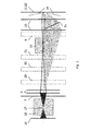
- the high photon densities in the laser beam focusses of fs and ps laser beams lead to the formation of intense air plasmas or plasmas of the protective gas used in the beam path to protect the optical components against contamination in the focal areas of the beam guiding and shaping system (see also US Pat Fig. 2 and 3 ).
- the plasma ignited by the intermediate focus (17) in the beam path of the laser beam between the beam homogenizer (4) and the mask (7) reduces the homogeneity of the fluence distribution of the laser beam in the plane of the mask (7) and that by the focus 1 (19) in The focus distance f of the objective (10) or the plasma ignited by the focus 2 (22) between the field lens system (8) and the objective (10) leads to a reduction in the quality of the imaged mask opening geometry, eg to reduce the sharpness of edges Image plane (11), so that no homogeneous removal of material via the predetermined by the opening geometries of the mask (7) surface areas on the substrate (13).
- These plasmas thus influence the optical quality of the subsequent laser beam components, in particular at high pulse repetition frequencies (repetition rates) of the laser, and cause a reduction in the level of detail of the image and thus also of the microstructures produced.
- vacuum cuvettes (18, 20, 23) are inserted into the beam path in the region of the foci (17, 19, 22). These cuvettes surround the focus area, have two windows (25) coated with transmitting interference layer systems or a window (25) and a pinhole (26) for the almost lossless transmission of the laser radiation, are evacuated to at least pre-vacuum and must be included in the calculation of the total optical Systems are involved.
- the entire optical system starting at the output of the laser (1) to the imaging lens (10) can be positioned in a vacuum chamber.
- an auxiliary lens (16) a field lens system (8) consisting of two lenses, for example, and an objective (10) consisting of two lenses, for example, are used.
- a field lens system (8) consisting of two lenses, for example
- an objective (10) consisting of two lenses, for example
- the intermediate focus (17) of the beam path is located between the additional lens (16) and the diaphragm-mask combination (6, 7).
- the focus 1 (19) of the imaging optical system consisting of the field lens system (8) and the objective (10) is located between the objective (10) and substrate surface (12); the image plane (11) is located on the substrate surface (12).
- the painted area (2a) illustrates the propagation of the diffracted laser beam portions of the diffraction orders 1 to 5 of a fs laser beam having a central wavelength of 775 nm, for example, from the center of a bar grating mask (7) having a grating period of 200 ⁇ m for the generation of a Beam intensity profile according to (14) in Fig. 1 , but with an in Fig. 1 not shown higher number of radiation transmitting and diffracting columns, go out.
- the vacuum cuvette 1 (18) surrounds the intermediate focus (17) and the vacuum cuvette 2 (20) surrounds the focus 1 (19).
- the imaging plane (11) is located on the substrate surface (12).
- the dotted rectangles indicate further 90 ° deflection mirrors (29, 30, 31) which can be used to fold the beam path and increase the compactness of the entire beam guidance and shaping system (see Fig. 5 ). If a sufficiently long space is available, the entire optical system can also be realized without the deflecting mirrors (9, 29, 30, 31).
- FIG. 4a schematically illustrated vacuum cuvette 1 (18) consists of two interchangeable plane-parallel circular windows (25) made of a material transparent to the laser wavelength material and a hollow cylindrical spacer (27) having a flange (28) for connecting a vacuum pump.
- the windows are attached vacuum-tight to the spacer.
- the vacuum cuvette 1 (18) is positioned so that the laser beam focus (17) is at its center.
- the distance between the window inner surfaces parallel to the optical axis is at least 100 mm.
- FIG. 4b schematically illustrated vacuum cuvette 2 (20) has only one transmitting window (25) for the transmission of the laser radiation coming from the lens; the diameter of the transmitting window surface must be chosen so large that the propagation of the diffracted laser beam components (2a) (see Fig. 2 ) at least the diffraction orders 1 to 3 is possible without hindrance.
- a disc with a pinhole (26) for the transmission of the laser radiation is inserted, because the intensity of the laser radiation in this area can be above the damage threshold of the window material.
- the cross-section of the pinhole (26) is only slightly larger than the total laser beam cross-section at that location and is in the range of one to several tens of square microns, in particular for the intended applications in the fields of micro- and nanostructuring.
- the vacuum required to avoid a plasma in the region of the focus (19) is achieved with the aid of a vacuum pump with sufficiently high suction power.
- a cross-jet protective gas nozzle (21) is mounted between the vacuum cuvette (20) and the substrate (13) Transverse gas flow generated.
- the beam-guiding variant 1 is preferably suitable for the realization of the smallest imaging cross-sections for the generation of structures with detail dimensions in the micro and nano-meter range, since after the focus 1 no further optical Components are present whose aberrations errors (eg aberrations of lenses) can affect the detail accuracy of the image negative.
- an additional lens (16) a field lens system (8) consisting of two lenses and an objective (10) consisting of two lenses are also used.
- a field lens system (8) consisting of two lenses and an objective (10) consisting of two lenses are also used.
- the intermediate focus (17) of the beam path is again between the additional lens (16) and the diaphragm mask combination (6,7).
- the focus 2 (22) of the imaging optical system consisting of the field lens system (8) and the objective (10) is located between field lens system (8) and objective (10) in this beam guidance variant 2, so that in order to avoid a plasma in the region of focus 2 (22) the vacuum cuvette (23) can be used with two transmitting windows for the laser radiation (see Fig.
- the diameter of the transmitting window surfaces must be chosen so large that the propagation of the diffracted laser beam components (2a) (see Fig. 3 ) at least the diffraction orders 1 to 3 is possible without hindrance.
- the imaging plane (11) is located on the substrate surface (12).
- a shielding gas nozzle system (24) is provided which generates a gas flow between the objective (10) and the substrate (13).
- the dotted rectangles indicate further 90 ° deflection mirrors (29, 30, 31), which can be used to fold the beam path and increase the compactness of the entire beam guidance and shaping system (see Fig. 5 ).
- the entire optical system can also be realized without the deflecting mirrors (9, 29, 30, 31).
- the beam guidance variant 2 is preferably suitable for the realization of larger imaging cross sections in the range of more than a few 10 ⁇ m 2 to 1 mm 2 .
- FIG. 5 an fs-laser mask projection system for the realization of the beam guidance variant 2 is shown (see Fig. 3 ).
- the dimension arrows with the dimensions indicate the distances of the optical components in millimeters.
- Four 90 ° deflection mirrors (29, 30, 31, 9) are used to achieve a compact design of the system and its integration into a FS-150-10 fs laser microstructuring system of the company "3D-Mikromac AG ", which is designed for microstructuring by means of the fs laser focus method to enable.
- this system uses a Clark MXR CPA 2010 laser with the following parameters: central wavelength 775 nm, pulse duration 150 fs, pulse energy 1 mJ, pulse repetition frequency 1 kHz; Beam diameter at the laser output 3 mm, Gaussian intensity distribution over the laser beam cross section.
- the intensity profile of the laser beam pulse is thereby formed in the homogeneous spot at location P at which the mask (7) is positioned.
- microstructures with detail dimensions down to the submicron range can be created. These include, for example, optical diffraction gratings for the visible wavelength range with grating periods of 1 ⁇ m and below.
- the three-dimensional microstructures preferably produced by layer-wise structured removal, have a high edge sharpness, a high wall steepness, and low wall and floor roughnesses. Due to the low thermal and shock wave load of the adjacent, non-structured substrate areas, material modifications and pocketing at the structural edges are avoided to a great extent in the structuring of brittle materials.
- a multi-beam processing in the micro range e.g. parallel generation of trench-shaped and truncated-pyramidal structures or parallel structuring or separation of thin-film stacks.
Landscapes
- Physics & Mathematics (AREA)
- Optics & Photonics (AREA)
- Engineering & Computer Science (AREA)
- Plasma & Fusion (AREA)
- Mechanical Engineering (AREA)
- Laser Beam Processing (AREA)
- Lasers (AREA)
Abstract
Eine Vorrichtung zur Maskenprojektion von Femto- und Pikosekunden-Laserstrahlen auf eine Substratoberfläche (12), in der, der aus Laserstrahlpulsen bestehende Laserstrahl (2) an einem Ort (P) der optischen Achse (5) zu Laserstrahlpulsen mit vergrößertem Laserstrahlquerschnitt oder zu Laserstrahlpulsen mit verkleinertem Laserstrahlquerschnitt geformt ist und eine homogene Intensitätsverteilung über den Laserstrahlquerschnitt besitzt. An dem Ort (P) sind nacheinander eine Blende (6) mit vorgegebener Blendenöffnungsgeometrie und eine Maske (7) mit vorgegebener Maskenöffnungsgeometrie in den Strahlengang positioniert. Die Vorrichtung beinhaltet weiter ein Feldlinsensystem (8) und ein Abbildungsobjektiv (10), derart positioniert, dass die von der Blende (6) und der Maske (7) transmittierten ungebeugten und gebeugten Strahlanteile der Laserstrahlpulse mit Hilfe des Feldlinsensystems (8) so in das Abbildungsobjektiv (10) mit vorgegebener Apertur gelenkt werden, dass in der Abbildungsebene eine detailgenaue, mit einem vorgegebenen Abbildungsverhältnis, verkleinerte Abbildung des von der Blende (6) und der Maske (7) erzeugten Intensitätsprofils über den Laserstrahlquerschnitt der Laserstrahlpulse entsteht. In einer Strahlführungsvariante 1 werden ein Zusatzlinsensystem (16), das Feldlinsensystem (8) und das Abbildungsobjektiv 810) relativ zueinander so positioniert, dass ein Fokus 1 zwischen dem Abbildungsobjektiv (10) und der Substratoberfläche (12) entsteht und in einer Strahlführungsvariante 2 werden das Zusatzlinsensystem (16), das Feldlinsensystem (8) und das Abbildungsobjektiv (10) relativ zueinander so positioniert, dass ein Fokus 2 zwischen dem Feldlinsensystem (8) und dem Abbildungsobjektiv (10) entsteht. Mindestens eine Vakuumküvette (20), die den Bereich des Fokus 1 bzw. des Fokus 2 umschließt ist vorhanden.A device for mask projection of femtosecond and picosecond laser beams on a substrate surface (12), in which, consisting of laser beam pulses laser beam (2) at a location (P) of the optical axis (5) to laser beam pulses with increased laser beam cross-section or to laser beam pulses reduced laser beam cross-section is shaped and has a homogeneous intensity distribution over the laser beam cross-section. At the location (P), a diaphragm (6) with a predetermined aperture geometry and a mask (7) with a predetermined mask aperture geometry are successively positioned in the beam path. The device further comprises a field lens system (8) and an imaging objective (10), positioned such that the undiffracted and diffracted beam portions of the laser beam pulses transmitted by the diaphragm (6) and the mask (7) into the field Imaging lens (10) are guided with a predetermined aperture, that in the image plane a detailed, with a predetermined ratio, reduced image of the diaphragm (6) and the mask (7) generated intensity profile on the laser beam cross section of the laser beam pulses. In a beam guidance variant 1, a supplementary lens system (16), the field lens system (8) and the imaging objective 810) are positioned relative to one another such that a focus 1 is formed between the imaging objective (10) and the substrate surface (12) and in a beam guidance variant 2 Additional lens system (16), the field lens system (8) and the imaging lens (10) positioned relative to each other so that a focus 2 between the field lens system (8) and the imaging lens (10) is formed. At least one vacuum cuvette (20) which encloses the area of the focus 1 or the focus 2 is present.
Description
Die Erfindung betrifft eine Vorrichtung zur Maskenprojektion von Femtosekunden- und Pikosekunden- Laserstrahlen.The invention relates to a device for mask projection of femtosecond and picosecond laser beams.
Verfahren und Vorrichtungen zur Maskenprojektion von Excimer-Laser-Strahlen sind bereits bekannt und werden zur Mikrostrukturierung von Festkörperoberflächen und insbesondere auch zur Erzeugung von dreidimensionalen Mikrostrukturen durch strukturierten schichtweisen Materialabtrag mit Hilfe von Excimerlasern eingesetzt (siehe u.a.
Weiter vergleichbare Verfahren und Vorrichtungen zur Maskenprojektion von Femtosekunden-Laserstrahlen und Pikosekunden-Laserstrahlen sind nach den Recherchen der Erfinder nicht bekannt. Femtosekunden-Laser (fs-Laser) und Pikosekunden-Laser (ps-Laser) emittieren Laserstrahlen mit zentralen Wellenlängen vorwiegend im Bereich von 775 nm bis 1064 nm, mit nahezu gaußförmiger Intensitätsverteilung über den Laserstrahlquerschnitt und mit wesentlich größerer Kohärenzlänge als die Excimerlaser. Diese fs- und ps-Laserstrahlen werden mittels handelsüblicher Fokussieroptiken zu Strahlen mit geringem Fokusquerschnitt geformt und beispielsweise auch zur Mikrostrukturierung von Festkörperoberflächen eingesetzt. Bei diesem Fokusverfahren ist die Intensitätsverteilung über den Fokusquerschnitt des Laserstrahls folglich ebenfalls gaußförmig und nicht homogen; am Ort des gaußschen Radius beträgt die Intensität nur das 1/e - fache, d.h. 36,8%, und am Ort des Strahlradius nur das 1/e2 - fache, d.h. 13,5 %, des Wertes im Strahlzentrum.Further comparable methods and devices for mask projection of femtosecond laser beams and picosecond laser beams are not known according to the research of the inventors. Femtosecond lasers (fs lasers) and picosecond lasers (ps lasers) emit laser beams with central wavelengths predominantly in the range of 775 nm to 1064 nm, with an almost Gaussian intensity distribution over the laser beam cross section and with a much greater coherence length than the excimer lasers. These fs and ps laser beams are shaped by means of commercially available focusing optics into beams with a low focus cross section and used, for example, for the microstructuring of solid surfaces. Consequently, in this focus method, the intensity distribution over the focus cross section of the laser beam is also Gaussian and not homogeneous; At the location of the Gaussian radius, the intensity is only 1 / e - fold, ie 36.8%, and at the location of the beam radius only 1 / e 2 times, ie 13.5%, of the value in the beam center.
Zur Erzeugung einer homogeneren Intensitätsverteilung über den Fokusquerschnitt von fs- und ps-Laserstrahlen sind Strahlhomogenisierer entwickelt worden, die zwischen Laserausgang und Fokussieroptik angeordnet werden. In den bisher bekannten Strahlhomogenisierern für fs- und ps-Laserstrahlen (siehe z.B.
Der Fokusradius des gaußverteilten Laserstrahls ist eine Funktion der Wellenlänge, des Radiuses des vom Laser emittierten Rohstrahls und der Fokusentfernung und lässt sich nicht beliebig verkleinern. In einer fs-Lasermikrostrukturierungsanlage vom Typ FS-150-10 der Firma 3D-Micromac AG Chemnitz mit einem Laser vom Typ CPA 2010 der Firma Clark Inc., USA, mit 775 nm zentrale Wellenlänge und 1 mJ (1 Millijoule) Pulsenergie und 150 fs Pulsdauer beträgt beispielsweise der kleinste Gaußsche Fokusradius 5,7 µm mit einem Objektiv mit 32 mm Brennweite, trotz 2-facher Strahlaufweitung von 3 mm Gaußschem Radius auf 6 mm und Homogenisierung.The focal radius of the Gaussian distributed laser beam is a function of the wavelength, the radius of the raw beam emitted by the laser and the focus distance and can not be arbitrarily reduced. In a FS-150-10 fs laser microstructuring unit from 3D-Micromac AG Chemnitz with a CPA 2010 laser from Clark Inc., USA, with 775 nm central wavelength and 1 mJ (1 millijoule) pulse energy and 150 fs Pulse duration, for example, the smallest Gaussian focus radius is 5.7 microns with a lens with 32 mm focal length, despite 2-fold beam expansion of 3 mm Gaussian radius to 6 mm and homogenization.
Die erreichbaren Fokusradien von minimal wenigen Mikrometern sind für eine Vielzahl von Anwendungen im Bereich der Mikro- und Nanostrukturierung zu groß, Strukturabmessungen von wenigen Mikrometern (µm) und darunter sind nicht erreichbar. Die Kantenschärfe der mittels des Fokusverfahrens erzeugten Mikrostrukturen mit Abmessungen von bis zu einigen zehn Mikrometern ist beispielsweise auch bei Pulsüberlappung des Laserstrahls zu gering. Optisch wirkende Transmissions- und Reflexionsgitter mit Gitterkonstanten bis zu einem Mikrometer und darunter für den sichtbaren Wellenlängenbereich können z.B. mit Hilfe des Fokusverfahrens nicht hergestellt werden.The achievable focus radii of a few microns are too large for a variety of applications in the field of micro- and nanostructuring, structural dimensions of a few micrometers (μm) and below are not achievable. The edge sharpness of the microstructures produced by means of the focus method with dimensions of up to a few tens of micrometers is too low, for example even with pulse overlapping of the laser beam. Optically acting transmission and reflection gratings with lattice constants of up to one micron and below for the visible wavelength range can e.g. not produced using the focus method.
Durch die gaußförmige Intensitätsverteilung über den Laserstrahlquerschnitt sind die Abtragstiefen über den Fokusquerschnitt und damit über die Breite einer strukturierten Spur in der Spurmitte wesentlich größer als am Spurrand. Dies führt beispielsweise beim mäanderförmigen Linienscan des fokussierten Laserstrahls zur Erzeugung eines flächenhaften Materialabtrags auch bei Spurüberlappung zu einer hohen Oberflächenrauhigkeit. Bei der Mikrostrukturierung und beim Trennen von Schichtstapeln, die aus mehreren Subschichten aus unterschiedlichen Materialien mit wenigen Nanometern Dicke bestehen, führt diese Intensitätsverteilung beispielsweise zum unvollständigen Schichtabtrag an den Spurrändern oder zur Beschädigung des Substratmaterials in Spurmitte. Bei Spurbreiten von größer 10 Mikrometer kann dieser Nachteil durch Einsatz eines Strahlhomogenisierers teilweise behoben werden; geringere Spurbreiten bis zu 1 Mikrometer und darunter mit gleichmäßiger Abtragstiefe sind aber mit Hilfe das Fokusverfahrens nicht zu erreichen.Due to the Gaussian intensity distribution over the laser beam cross section, the removal depths over the focus cross section and therefore across the width of a structured track in the track center are substantially greater than at the track edge. In the case of the meander-shaped line scan of the focused laser beam, for example, this leads to a high surface roughness even in the case of track overlap in order to produce a planar removal of material. In the microstructuring and in the separation of layer stacks, which consist of several sublayers of different materials with a few nanometers thickness, this intensity distribution leads, for example, to incomplete layer removal at the track edges or to damage of the substrate material in the middle of the track. For track widths greater than 10 micrometers, this disadvantage can be partially remedied by using a beam homogenizer; however, smaller track widths of up to 1 micrometer and below with a uniform excavation depth can not be achieved with the aid of the focus method.
Die Erzeugung eines vorgegeben strukturierten Intensitätsprofils über den Laserstrahlquerschnitt ist beim Fokusverfahren nicht möglich.The generation of a predetermined structured intensity profile over the laser beam cross section is not possible in the focus method.
Mit der erfindungsgemäßen Lösung sollen die Nachteile der bisher eingesetzten fs- und ps-Fokusverfahren überwunden werden. Insbesondere sollen eine homogene Intensitätsverteilung über den gesamten Abbildungsquerschnitt auf der zu bearbeitenden Substratoberfläche (Werkstückoberfläche) und, im Vergleich zu den mit dem Fokusverfahren einstellbaren Fokusquerschnitten, wesentlich kleinere Abbildungsquerschnitte, beispielsweise eine kreisförmige Abbildungsquerschnittsfläche von 1 µm Durchmesser bzw. eine quadratische Abbildungsquerschnittsfläche von 1 µm2 bei zentralen Laserstrahlgrundwellenlängen vorzugsweise im Bereich von 775 nm bis 1064 nm sowie bei Einsatz der Frequenzverdopplung (SHG) oder Frequenzverdreifachung (THG) oder Frequenzvervierfachung (FHG) des Laserstrahls auch darunter, d.h. im Bereich von einigen 100 Nanometern, erreicht werden.With the solution according to the invention, the disadvantages of the previously used fs and ps focus methods are to be overcome. In particular, to a homogeneous intensity distribution across the entire image cross-section of the substrate to be processed surface (work surface) and, in comparison with the adjustable with the focus method focus cross sections considerably smaller picture cross-sections, for example a circular image cross-sectional area of 1 micron diameter or a square figure cross-sectional area of 1 micron 2 at central laser beam fundamental wavelengths, preferably in the range from 775 nm to 1064 nm, and when using the frequency doubling (SHG) or frequency tripling (THG) or frequency quadrupling (FHG) of the laser beam also below, ie in the range of a few 100 nanometers.
Bei genügend hoher Pulsenergie des fs- und ps-Lasers von wenigstens 1 mJ und der daraus resultierenden und auch von der für die Strukturierung erforderliche Strahlintensität und dem Abbildungsverhältnis abhängigen möglichen einstellbaren Querschnittsgröße des homogenen Flecks soll des Weiteren mit Hilfe einer im homogenen Fleck positionierten Maske mit vorgegebener Geometrie der transmittierenden Maskenflächenbereiche aus der homogenen Intensitätsverteilung des Laserstrahls auch das für die Erzeugung einer vorgegebenen Mikrostruktur erforderliche Intensitätsprofil über den Laserstrahlquerschnitt, z.B. ein gitterförmiges Intensitätsprofil, geformt und mittels einer geeigneten Fokussieroptik mit einem vorgegebenen verkleinernden Abbildungsverhältnis auf dem zu strukturierenden Substrat abgebildet werden können.At sufficiently high pulse energy of the fs and ps laser of at least 1 mJ and the resulting resulting and also of the required for the structuring beam intensity and the imaging ratio dependent possible adjustable cross-sectional size of the homogeneous spot should also with the help of a positioned in the homogeneous spot mask given geometry of the transmitting mask surface areas from the homogeneous intensity distribution of the laser beam and the required for the production of a predetermined microstructure intensity profile over the laser beam cross-section, eg a lattice-shaped intensity profile, shaped and can be imaged by means of a suitable focusing optics with a predetermined decreasing Abbildungsverhältnis on the substrate to be structured.
Die erfindungsgemäße Lösung beinhaltet eine Vorrichtung zur Maskenprojektion von Femto- und Pikosekunden-Laserstrahlen auf eine Substratoberfläche, in der, der aus Laserstrahlpulsen bestehende Laserstrahl an einem Ort der optischen Achse zu Laserstrahlpulsen mit vergrößertem Laserstrahlquerschnitt oder zu Laserstrahlpulsen mit verkleinertem Laserstrahlquerschnitt geformt ist und eine homogene Intensitätsverteilung über den Laserstrahlquerschnitt besitzt. An dem Ort sind nacheinander eine Blende mit vorgegebener Blendenöffnungsgeometrie und eine Maske mit vorgegebener Maskenöffnungsgeometrie in den Strahlengang positioniert. Die Vorrichtung beinhaltet weiter ein Feldlinsensystem und ein Abbildungsobjektiv, derart positioniert, dass die von der Blende und der Maske transmittierten ungebeugten und gebeugten Strahlanteile der Laserstrahlpulse mit Hilfe des Feldlinsensystems so in das Abbildungsobjektiv mit vorgegebener Apertur gelenkt werden, dass in der Abbildungsebene eine detailgenaue, mit einem vorgegebenen Abbildungsverhältnis, verkleinerte Abbildung des von der Blende und der Maske erzeugten Intensitätsprofils über den Laserstrahlquerschnitt der Laserstrahlpulse entsteht. In einer Strahlführungsvariante 1 werden ein Zusatzlinsensystem, das Feldlinsensystem und das Abbildungsobjektiv relativ zueinander so positioniert, dass ein Fokus 1 zwischen dem Abbildungsobjektiv und der Substratoberfläche entsteht und in einer Strahlführungsvariante 2 werden das Zusatzlinsensystem, das Feldlinsensystem und das Abbildungsobjektiv relativ zueinander so positioniert, dass ein Fokus 2 zwischen dem Feldlinsensystem und dem Abbildungsobjektiv entsteht. Mindestens eine Vakuumküvette, die den Bereich des Fokus 1 bzw. des Fokus 2 umschließt ist vorhanden.The solution according to the invention comprises a device for mask projection of femto- and picosecond laser beams onto a substrate surface in which the laser beam consisting of laser beam pulses is shaped at a location of the optical axis into laser beam pulses with increased laser beam cross-section or laser beam pulses with reduced laser beam cross-section and a homogeneous intensity distribution has over the laser beam cross section. At the location, a diaphragm with a predetermined aperture geometry and a mask with a predetermined mask aperture geometry are successively positioned in the beam path. The device further includes a field lens system and an imaging lens, positioned such that the transmitted from the aperture and the mask undeflected and diffracted beam portions of the laser beam pulses are directed by means of the field lens system in the imaging lens with a predetermined aperture that in the image plane a detailed, with a predetermined imaging ratio, reduced imaging of the intensity profile generated by the diaphragm and the mask over the laser beam cross section of the laser beam pulses is formed. In a
In einer weiteren bevorzugten Ausführung ist zwischen dem Feldlinsensystem und dem Abbildungsobjektiv ein 90°-Umlenkspiegel angeordnet.In a further preferred embodiment, a 90 ° deflecting mirror is arranged between the field lens system and the imaging objective.
In einer weiteren bevorzugten Ausführung sind Mittel zur Variation des Abstandes zwischen der Hauptebene des Abbildungsobjektivs und der Substratoberfläche vorhanden, mit dessen Hilfe die Abbildungsebene, deren vorgegebene Position im Abstand der Bildweite von der Hauptebene des Abbildungsobjektivs durch Variation des Abstandes zwischen der Hauptebene des Abbildungsobjektivs und der Substratoberfläche wahlweise über, auf oder unter die Substratoberfläche gelegt wird.In a further preferred embodiment, means are provided for varying the distance between the main plane of the imaging objective and the substrate surface, with the aid of which the imaging plane, whose predetermined position at the distance of the image distance from the main plane of the imaging objective by varying the Distance between the main plane of the imaging lens and the substrate surface is optionally placed over, on or below the substrate surface.
In einer weiteren bevorzugten Ausführung sind die Mittel zur Variation des Abstandes zwischen der Hauptebene des Abbildungsobjektivs und der Substratoberfläche die z-Achse des xyz-Koordinatentischs, auf dem das Substrat befestigt ist.In another preferred embodiment, the means for varying the distance between the principal plane of the imaging lens and the substrate surface is the z-axis of the xyz coordinate stage on which the substrate is mounted.
In einer weiteren bevorzugten Ausführung sind die Mittel zur Variation des Abstandes zwischen der Hauptebene des Abbildungsobjektivs und der Substratoberfläche die Linearachsen, mit deren Hilfe das an diesen Linearachsen befestigte Feldlinsensystem und das Abbildungsobjektiv entlang der optischen Achse um einen vorgegebenen Weg verschiebbar angeordnet sind.In a further preferred embodiment, the means for varying the distance between the main plane of the imaging objective and the substrate surface are the linear axes, with the aid of which the field lens system attached to these linear axes and the imaging objective are displaceable along the optical axis by a predetermined path.
In einer weiteren bevorzugten Ausführung ist in der Strahlführungsvariante 1 zwischen der mindestens einen Vakuumküvette und der Substratoberfläche eine Cross-Jet-Schutzgasdüse angeordnet.In a further preferred embodiment, a cross-jet protective gas nozzle is arranged in the
In einer weiteren bevorzugten Ausführung ist in der Strahlführungsvariante 2 zwischen dem Abbildungsobjektiv und der Substratoberfläche eine Schutzgasdüsensystem angebracht.In a further preferred embodiment, a protective gas nozzle system is mounted in the
In einer weiteren bevorzugten Ausführung sind die Aperturen der optischen Bauteile, die wenigstens das Feldlinsensystem, das Abbildungsobjektiv und die mindestens eine Vakuumküvette umfassen, so groß gewählt, dass auch die infolge der vorgegebenen Maskenöffnungsgeometrie der Maske, gebeugten Laserstrahlanteile von der ersten bis wenigstens zur dritten Beugungsordnung auf der Substratoberfläche mit abgebildet werden.In a further preferred embodiment, the apertures of the optical components which comprise at least the field lens system, the imaging objective and the at least one vacuum cuvette are chosen to be so large that the laser beam portions diffracted as a result of the mask mask opening geometry also vary from the first to at least the third order of diffraction be imaged on the substrate surface.
In einer weiteren bevorzugten Ausführung wird der eingesetzte Laser im burst mode betrieben.In a further preferred embodiment, the laser used is operated in burst mode .
In einer weiteren bevorzugten Ausführung umfasst die Vorrichtung weiter einen Strahlaufweiter oder einen Strahlquerschnittsverringerer; und eine zwischen dem Laser und dem Strahlaufweiter oder Strahlquerschnittsverringerer positionierte Vorrichtung zur Erzeugung der zweiten Harmonischen (Frequenzverdopplung, SHG) oder der dritten Harmonischen (Frequenzverdreifachung, THG) oder der vierten Harmonischen (Frequenzvervierfachung, FHG). Die Femtosekunden-Laserstrahl-Pulse oder die Pikosekunden-Laserstrahl-Pulse durchlaufen nach ihrem Austritt aus dem Laser jeweils die Vorrichtung zur Erzeugung der zweiten Harmonischen (Frequenzverdopplung, SHG) oder der dritten Harmonischen (Frequenzverdreifachung, THG) oder der vierten Harmonischen (Frequenzvervierfachung, FHG), und wenigstens sind der Strahlaufweiter oder Strahlquerschnittsverringerer, das Zusatzlinsensystem, die Blende, die Maske, das Feldlinsensystem, das Abbildungsobjektiv und die mindestens eine Vakuumküvette für die Transmission der entstehenden Photonenstrahlung mit der halben oder eindrittel oder einviertel der Grund-Wellenlänge geeignet konstruiert.In a further preferred embodiment, the apparatus further comprises a beam expander or a beam cross-section reducer; and a second harmonic generator (frequency doubling, SHG) or third harmonic (frequency tripling, THG) or fourth harmonic (frequency quadrupling, FHG) positioned between the laser and the beam expander or beam cross-section reducer. The femtosecond laser beam pulses or the picosecond laser beam pulses each pass through the second harmonic generator (frequency doubling, SHG) or the third harmonic (frequency tripling, THG) or the fourth harmonic (frequency quadrupling, FHG) after leaving the laser ), and at least the beam expander or beam cross-section reducer, the auxiliary lens system, the aperture, the mask, the field lens system, the imaging lens and the at least one vacuum cuvette for the transmission of the resulting photon radiation designed with half or one-third or one-quarter of the fundamental wavelength suitably.
Die Erfindung wird im Folgenden anhand schematisierter Zeichnungen näher erläutert:
-
Fig. 1 zeigt die schematische Anordnung der optischen Bauelemente des Strahlführungs- und -Formungssystems zur Realisierung des Femtosekunden- und Pikosekunden-Laser-Maskenprojektionsverfahrens (fspsMP); -
Fig. 2 zeigt den berechneten optischen Weg der Laserstrahlen im Strahlführungs- und -Formungssystems gemäßFig. 1 für dieStrahlführungsvariante 1 mit den Fokuslagen zwischen Zusatzlinse (16) und Maske (7) und zwischen Objektiv (10) und Substrat (13); -
Fig. 3 zeigt den berechneten optischen Weg der Laserstrahlen im Strahlführungs- und -Formungssystems gemäßFig. 1 für dieStrahlführungsvariante 2 mit den Fokuslagen zwischen Zusatzlinse (16) und Maske (7) und zwischen Feldlinsensystem (8) und Objektiv (10); -
Fig. 4a zeigt schematisch den Querschnitt der Vakuum-Küvette 1, die zwischen Zusatzlinse (16) und Maske (7) angeordnet ist, und dergleichartigen Vakuumküvette 3, die zwischen Feldlinsensystem (8) und Objektiv (10) angeordnet ist; -
Fig. 4b zeigt schematisch den Querschnitt derVakuumküvette 2, die zwischen Objektiv (10) und Substrat (13) angeordnet ist, mit angefügter Cross-Jet-Schutzgasdüse (21); und -
Fig. 5 zeigt beispielhaft die Anordnung der optischen Bauelemente eines realisierten Femtosekunden- und Pikosekunden-Laser-Maskenprojektionssystems mit vier Umlenkspiegeln zur Verkleinerung der Gesamtabmessungen des Systems.
-
Fig. 1 shows the schematic arrangement of the optical components of the beam guiding and shaping system for realizing the femtosecond and picosecond laser mask projection method (fspsMP); -
Fig. 2 shows the calculated optical path of the laser beams in the beam guiding and shaping system according to FIGFig. 1 for the beam-guidingvariant 1 with the focal positions between additional lens (16) and mask (7) and between lens (10) and substrate (13); -
Fig. 3 shows the calculated optical path of the laser beams in the beam guiding and shaping system according to FIGFig. 1 for thebeam guidance variant 2 with the focal positions between additional lens (16) and mask (7) and between field lens system (8) and lens (10); -
Fig. 4a shows schematically the cross section of thevacuum cuvette 1, which is arranged between the additional lens (16) and mask (7), and thesimilar vacuum cuvette 3, which is arranged between field lens system (8) and lens (10); -
Fig. 4b schematically shows the cross section of thevacuum cuvette 2, which is arranged between the lens (10) and substrate (13), with attached cross-jet protective gas nozzle (21); and -
Fig. 5 FIG. 4 shows by way of example the arrangement of the optical components of a realized femtosecond and picosecond laser mask projection system with four deflection mirrors for reducing the overall dimensions of the system.
Gemäß
Danach passiert der Laserstrahl einen Strahlhomogenisierer (4) und wahlweise noch eine Zusatzlinse oder ein Zusatzlinsensystem (16), die im homogenen Fleck am Ort (P) auf der optischen Achse (5) des Laserstrahls (Strahlachse) eine homogene, als top-flat Intensitätsprofil bezeichnete Intensitätsverteilung (IAH) des Laserstrahls erzeugen.Thereafter, the laser beam passes through a beam homogenizer (4) and optionally an additional lens or a supplementary lens system (16) in the homogeneous spot at the location (P) on the optical axis (5) of the laser beam (beam axis) a homogeneous, top-flat intensity profile Generate designated intensity distribution (IAH) of the laser beam.
Zur Erzeugung eines vorgegeben strukturierten Intensitätsprofils der Laserstrahlpulse über den Laserstrahlquerschnitt werden nacheinander, in sehr geringem Abstand zueinander von bis zu wenigen zehntel Millimeter oder im Kontakt miteinander, eine Blende (6) mit vorgegebener Blendenöffnungsgeometrie und eine Maske (7) mit vorgegebener Maskenöffnungsgeometrie am Ort (P) positioniert. Die von der Blende (6) und der im homogenen Fleck am Ort (P) positionierten Maske (7) transmittierten ungebeugten und gebeugten Strahlanteile der Laserstrahlpulse werden mit Hilfe einer Feldlinse oder eines Feldlinsensystems (8) und, nach der Reflexion an wenigstens einem 90°-Umlenkspiegel (9), eines Objektivs (10) in der Abbildungsebene (11) abgebildet. In der Abbildungsebene (11), deren vorgegebene Position im Abstand der Bildweite b von der Hauptebene (35) des Objektiv (10) durch Variation des Abstandes (s) zwischen der Hauptebene (35) des Objektivs (10) und der Oberfläche (12) des Substrats (13) wahlweise über (siehe
Die Variation des Abstandes (s) zwischen der Hauptebene (35) des Abbildungsobjektivs (10) und der Substratoberfläche (12) erfolgt vorzugsweise mit Hilfe der z-Achse des xyz-Koordinatentischs (32), auf dem das Substrat (13) positioniert ist. Bei nicht verfahrbarem Substrat kann die Variation des Abstands (s) auch mit Hilfe der Linearachsen (33, 34) erfolgen, an denen die Feldlinse bzw. das Feldlinsensystem (8) und das Objektiv (10) befestigt sind und somit um einen vorgegeben Weg entlang der optischen Achse (5) verschiebbar sind, ohne dass sich die Abbildungseigenschaften des optischen Systems ändern.The variation of the distance (s) between the main plane (35) of the imaging objective (10) and the substrate surface (12) is preferably effected by means of the z-axis of the xyz coordinate stage (32) on which the substrate (13) is positioned. With a non-movable substrate, the variation of the distance (s) can also take place with the aid of the linear axes (33, 34), to which the field lens or the field lens system (8) and the objective (10) are fastened and thus along a predetermined path the optical axis (5) are displaceable, without changing the imaging properties of the optical system.
Die mittels des Strahlaufweiters (3) realisierbare Querschnittsvergrößerung des Laserstrahls, der aus dieser Querschnittsvergrößerung und der Fokusentfernung (Brennweite) der Zusatzlinse oder des Zusatzlinsensystems (16) resultierende Querschnitt des Laserstrahls im homogenen Fleck in der Ebene der Maske (7) und das realisierbare Abbildungsverhältnis V hängen von der Pulsenergie des Laserstrahls ab und müssen so aufeinander abgestimmt werden, dass in der Abbildungsebene (11) die für den geplanten Laserbearbeitungsprozess erforderliche Laserstrahlfluenz erreicht wird. Wenn der vom Laser emittierte Strahl eine zu geringe Pulsenergie besitzt, so dass in der Ebene der Maske (7) die Fluenz zu klein ist, um beim vorgegebenen Abbildungsverhältnis V die notwendige Fluenz für den Materialabtrag in der Abbildungsebene (11) zu erreichen, muss an Stelle des Strahlaufweiters (3) ein Strahlquerschnittsverringerer eingesetzt werden. Das kann z.B. bei Frequenzverdopplung (SHG) oder Frequenzverdreifachung (THG) oder Frequenzvervierfachung (FHG) der Grundwellenlänge des Laserstrahls mit Hilfe der optionalen Vorrichtung (15) erforderlich sein; bei der Frequenzverdopplung des Lasers vom Typ CPA 2010 der Firma Clark Inc. mit 775 nm zentraler Grundwellenlänge stehen beispielsweise nur etwa 40 % und bei Frequenzverdreifachung stehen nur noch 6-8 % der ursprünglichen Pulsenergie des Laserstrahls mit der Grundwellenlänge zur Verfügung. Die nutzbare Maskenfläche wäre dann aber sehr klein, sie würde jedoch ausreichen, um mit einer kleinen Blenden- bzw. Maskenöffnung, d.h. mit einem sehr geringen Abbildungsquerschnitt von beispielsweise 1 µm2 und darunter auf dem Substrat, sehr feine Bohrungen und genaue Strukturkanten sowie beim schichtweisen strukturierten Materialabtrag auch sehr kleine dreidimensionale Mikrostrukturen (3d-Strukturen) zu erzeugen.The cross-sectional enlargement of the laser beam that can be realized by means of the beam expander (3), the cross section of the laser beam in the homogeneous spot in the plane of the mask (7) resulting from this cross-sectional enlargement and the focal distance of the additional lens or auxiliary lens system (16) and the realizable imaging ratio V Depend on the pulse energy of the laser beam and must be coordinated so that in the imaging plane (11) required for the planned laser processing process laser beam fluence is achieved. If the beam emitted by the laser has too low a pulse energy, so that in the plane of the mask (7) the fluence is too small to be at the given imaging ratio In order to achieve the necessary fluence for the removal of material in the imaging plane (11), a beam cross-section reducer must be used instead of the beam expander (3). This may be necessary, for example, in frequency doubling (SHG) or frequency tripling (THG) or frequency quadrupling (FHG) of the fundamental wavelength of the laser beam with the aid of the optional device (15); For example, in the frequency doubling of the CPA 2010 laser from Clark Inc. with 775 nm central fundamental wavelength, only about 40% and with frequency tripling are only 6-8% of the original pulse energy of the laser beam with the fundamental wavelength available. The usable mask surface would then be very small, but it would be sufficient, with a small Aperture or mask opening, ie with a very small imaging cross-section of, for example, 1 micron 2 and below on the substrate, very fine holes and precise structure edges and the layers structured material removal even very small three-dimensional microstructures (3d structures) to produce.
Eine detailgenaue, mit einem vorgegebenen Abbildungsverhältnis (V), verkleinerte Abbildung (14) des von der Blende (6) und der Maske (7) erzeugten Intensitätsprofils über den Laserstrahlquerschnitt und damit die Erzeugung von vorgegebenen Mikrostrukturen mit Hilfe des fs- und ps-Maskenprojektionsverfahrens ist nur dann möglich, wenn auch die an den transmittierenden Maskenbereichen, z.B. an einer Strichgitter-Maske, gebeugten Laserstrahlanteile zur Abbildungsebene (11) gelangen und zur Abbildung beitragen, da sonst ein Informationsverlust auftritt und die Transmissionsgeometrie der Maske und damit das von der Maske erzeugte, vorgegebene strukturierte Intensitätsprofil des Laserstrahls nur ungenau in der Abbildungsebene abgebildet wird. Alle optischen Bauteile, die nach der Maske (7) angeordnet sind, müssen deshalb eine genügend große Apertur besitzen, damit auch die gebeugten Laserstrahlanteile abgebildet werden und mit zur Abbildung beitragen können. Simulationsrechnungen und Experimente habe ergeben, dass die erste bis wenigstens die dritte Beugungsordnung mit abgebildet werden muss, um eine detailgenaue Abbildung des von der Maske erzeugten Intensitätsprofils der Laserstrahlung in der Abbildungsebene (11) zu erhalten.A detailed, with a predetermined mapping ratio (V), reduced image (14) of the intensity profile generated by the diaphragm (6) and the mask (7) over the laser beam cross section and thus the generation of predetermined microstructures using the fs and ps mask projection method is only possible if the at the transmitting mask areas, eg at a grating mask, diffracted laser beam components to the imaging plane (11) and contribute to the image, otherwise a loss of information occurs and the transmission geometry of the mask and thus generated by the mask, predetermined structured intensity profile of the laser beam is imaged only inaccurately in the image plane. All optical components which are arranged according to the mask (7) must therefore have a sufficiently large aperture so that the diffracted laser beam components can also be imaged and contribute to the imaging. Simulation calculations and experiments have shown that the first to at least the third order of diffraction must also be mapped in order to obtain a detailed representation of the mask generated by the mask intensity profile of the laser radiation in the imaging plane (11).
Die hohen Photonendichten in den Laserstrahlfokussen von fs- und ps-Laserstrahlen führen zur Entstehung von intensiven Luft-Plasmen bzw. Plasmen des im Strahlengang zum Schutz der optischen Bauelemente vor Kontaminationen eingesetzten Schutzgases in den Fokusbereichen des Strahlführungs- und -Formungssystems (siehe auch
Um das Auftreten dieser Plasmen zu vermeiden, werden im Bereich der Fokusse (17, 19, 22) Vakuumküvetten (18, 20, 23) in den Strahlengang eingefügt. Diese Küvetten umgeben den Fokusbereich, besitzen zwei mit transmittierenden Interferenzschichtsystemen beschichtete Fenster (25) oder ein Fenster (25) und eine Lochblende (26) für die nahezu verlustlose Transmission der Laserstrahlung, werden bis wenigstens auf Vorvakuum evakuiert und müssen in die Berechnung des gesamten optischen Systems mit einbezogen werden. Alternativ kann auch das gesamte optische System, beginnend am Ausgang des Lasers (1) bis zu dem Abbildungsobjektiv (10) in eine Vakuumkammer positioniert werden.In order to avoid the occurrence of these plasmas, vacuum cuvettes (18, 20, 23) are inserted into the beam path in the region of the foci (17, 19, 22). These cuvettes surround the focus area, have two windows (25) coated with transmitting interference layer systems or a window (25) and a pinhole (26) for the almost lossless transmission of the laser radiation, are evacuated to at least pre-vacuum and must be included in the calculation of the total optical Systems are involved. Alternatively, the entire optical system, starting at the output of the laser (1) to the imaging lens (10) can be positioned in a vacuum chamber.
Ein besonderer, bisher für ausgewählte ps-Laser-Typen entwickelter Betriebsmodus ist der "burst-mode". Im "burst mode" werden im Unterschied zum Einzelpulsbetrieb eines ps-Lasers mit einer vorgegebenen Repetitionsrate keine ps-Laserstrahlpulse sondern ps-Laserstrahl-Pulszüge generiert mit zeitlichen Puls zu Puls-Abständen der einzelnen Pulse im Zug ("burst") im Bereich von einigen Zehn Nanosekunden, typisch 20 ns, und zeitlichen Pulszug zu Pulszug-Abständen im Bereich von 10-3 bis 10-7 Sekunden, typisch 10 µs, d.h. mit einer Pulszug-Wiederholfrequenz (Repetitionsrate des Lasers) von 1kHz bis 10 MHz. Die mögliche maximale Repetitionsrate des ps-Lasers im "burst mode" hängt von der Anzahl der einzelnen Pulse im Pulszug ab und wird durch diese begrenzt. Die Pulsdauer der Einzelpulse des ps-Lasers und die Pulsdauern der Pulse im "burst mode" sind gleich. Ein Pulszug ("burst") kann, einstellbar, aus bis zu 20 einzelnen ps-Pulsen bestehen. Die Pulsenergie der einzelnen Pulse im Pulszug kann sich dabei nach einer für das Lasergerät typischen Funktion exponentiell verringern bei gleichem zeitlichen Puls zu Puls-Abstand der einzelnen Pulse im Pulszug (z.B. Pulszug des ps-Lasers vom Typ " Lumera Hyperrapid" der Firma "Lumera Laser GmbH") oder der Verlauf der Pulsenergie der Einzelpulse im Pulszug kann vorgegeben werden, so dass eine gleich bleibende Pulsenergie der Pulse im Pulszug oder eine Verringerung oder Vergrößerung der Pulsenergie der Pulse im Pulszug oder auch zuerst eine Verringerung und danach wieder eine Vergrößerung der Pulsenergie der Pulse im Pulszug möglich ist; des Weiteren können auch ein Puls oder mehrere Pulse im Pulszug unterdrückt werden (z.B. im "FlexBurst™-Mode" bei den Lasertypen "Time-Bandwidth Duetto™" und " Time-Bandwidth Fuego™" der Firma "Time-Bandwidth Products"). Eine Frequenzverdopplung oder Frequenzverdreifachung (SHG oder THG) der Laserstrahlung ist auch im "burst mode"- Betrieb des ps-Lasers möglich. Die "burst mode"-Bearbeitung weist im Vergleich zur ps-Laser-Bearbeitung mit Einzelpulsen folgende Vorteile auf:
- höhere Abtragraten bei der Strukturierung von metallischen Werkstoffen im Vergleich zur ps-Pulsbestrahlung mit Einzelpulsen mit der gleichen Energie wie die Pulszug-Gesamtenergie, d.h. bei den gleichen Fluenzen der Einzelpulse und der Pulszüge, und bei gleichem Puls zu Puls - Abstand (Überlappungsgrad) der Einzelpulse und der Pulszüge, d.h. bei der gleichen Repetitionsrate der Einzelpulse wie die Pulszugrepetitionsrate;
- bessere Qualität, insbesondere geringere Flächenrauhigkeiten, der erzeugten Strukturformen in metallischen Werkstoffen im Vergleich zur ps-Pulsbestrahlung mit Einzelpulsen bei gleichem Überlappungsgrad, auch bei höheren Fluenzen des "burst".
- higher ablation rates in the structuring of metallic materials compared to ps pulse irradiation with single pulses with the same energy as the pulse train total energy, ie at the same fluences of the individual pulses and the pulse trains, and at the same pulse to pulse - distance (degree of overlap) of the individual pulses and the pulse trains, ie at the same repetition rate of the individual pulses as the pulse train repetition rate;
- better quality, especially lower surface roughness, of the generated structural forms in metallic materials in comparison to the ps pulse irradiation with single pulses with the same degree of overlap, even at higher fluences of the "burst".
Die Erzeugung des "burst mode" von Femtosekunden-Laserstrahlpulsen befindet sich gegenwärtig noch im Stadium der Grundlagenforschung (z.B. J. Hernandez-Ruedal, J. Siegel, D. Puerto2, M. Galvan-Sosa, W. Gawelda3, and J. Solis : Ad-hoc design of temporally shaped fs laser pulses based on plasma dynamics for deep ablation in fused silica, Appl.Phys. A (2013) 112).The generation of the "burst mode" of femtosecond laser beam pulses is currently still in the basic research stage (eg J. Hernandez-Ruedal, J. Siegel, D. Puerto2, M. Galvan-Sosa, W. Gawelda3, and J. Solis: Ad hoc design of temporally shaped laser pulses based on plasma dynamics for deep ablation in fused silica, Appl. Phys. A (2013) 112).
In der Strahlführungsvariante 1 gemäß
Die in
Die in
An Stelle des Fensters für den Austritt der Laserstrahlung nach dem Fokus in Richtung Substratoberfläche (12) ist eine Scheibe mit einer Lochblende (26) für die Transmission der Laserstrahlung eingefügt, weil die Intensität der Laserstrahlung in diesem Bereich über der Zerstörschwelle des Fenstermaterials liegen kann. Der Querschnitt der Lochblende (26) ist nur geringfügig größer als der Laserstrahlgesamtquerschnitt an diesem Ort und liegt insbesondere für die geplanten Anwendungen auf den Gebieten Mikro- und Nanostrukturierung im Bereich von einem bis zu einigen zehn Quadratmikrometern. Das für die Vermeidung eines Plasmas im Bereich des Fokus (19) erforderliche Vakuum wird mit Hilfe einer Vakuumpumpe mit genügend hoher Saugleistung erreicht. Zum Schutz des Fensters (25) der Vakuumküvette 2 (20) vor der Belegung mit ablatiertem Material vom Substrat (13) ist eine Cross-Jet-Schutzgasdüse (21) angebracht, die zwischen der Vakuumküvette (20) und dem Substrat (13) eine Quer-Gasströmung erzeugt.Instead of the window for the exit of the laser radiation after the focus in the direction of the substrate surface (12) a disc with a pinhole (26) for the transmission of the laser radiation is inserted, because the intensity of the laser radiation in this area can be above the damage threshold of the window material. The cross-section of the pinhole (26) is only slightly larger than the total laser beam cross-section at that location and is in the range of one to several tens of square microns, in particular for the intended applications in the fields of micro- and nanostructuring. The vacuum required to avoid a plasma in the region of the focus (19) is achieved with the aid of a vacuum pump with sufficiently high suction power. To protect the window (25) of the vacuum cuvette 2 (20) before the deposition of ablated material from the substrate (13) a cross-jet protective gas nozzle (21) is mounted between the vacuum cuvette (20) and the substrate (13) Transverse gas flow generated.
Die Strahlführungsvariante 1 ist vorzugsweise für die Realisierung geringster Abbildungsquerschnitte zur Erzeugung von Strukturen mit Detailabmessungen im Mikro- und Nano-Meterbereich geeignet, da nach dem Fokus 1 keine weiteren optischen Bauelemente vorhanden sind, deren Abbildungsfehler Fehler (z.B. Abbildungsfehler von Linsen) die Detailgenauigkeit der Abbildung negativ beeinflussen können.The beam-guiding
In der Strahlführungsvariante 2 gemäß
Die punktiert dargestellten Rechtecke deuten weitere 90°- Umlenkspiegel (29, 30, 31) an, die zur Faltung des Strahlengangs genutzt werden können und die Kompaktheit des gesamten Strahlführungs- und -Formungssystems erhöhen (siehe
Wenn ein genügend langer Raum zur Verfügung steht, kann das gesamte optische System aber auch ohne die Umlenkspiegel (9, 29, 30, 31) realisiert werden.If a sufficiently long space is available, the entire optical system can also be realized without the deflecting mirrors (9, 29, 30, 31).
Die Strahlführungsvariante 2 ist vorzugsweise für die Realisierung größerer Abbildungsquerschnitte im Bereich von größer einigen 10 µm2 bis zu 1 mm2 geeignet.The
In
Mit Hilfe des Feldlinsensystems (8) und dem Abbildungsobjektiv (10), das eine Brennweite von 100 mm besitzt, wird in der Bildweite b = 110 mm in der Abbildungsebene (11) eine verkleinerte Abbildung (14) des mit der Blende (6) erzeugten Laserstrahlquerschnitts und mit der Maske (7) geformten Laserstrahlintensitätsprofils mit einem Abbildungsverhältnis von V = 11:1 und mit einer Laserstrahlpulsfluenz von 280 mJ/cm2 erzeugt.With the help of the field lens system (8) and the imaging lens (10), which has a focal length of 100 mm, in the image width b = 110 mm in the image plane (11) a reduced image (14) of the generated with the diaphragm (6) Laser beam cross section and with the mask (7) shaped laser beam intensity profile with a mapping ratio of V = 11: 1 and with a laser beam pulse fluence of 280 mJ / cm 2 generated.
Durch den Einsatz des fs- und ps-Maskenprojektionsverfahrens können Mikrostrukturen mit Detailabmessungen bis in den Submikrometerbereich erzeugt werden. Dazu gehören beispielsweise optische Beugungsgitter für den sichtbaren Wellenlängenbereich mit Gitterperioden von 1 µm und darunter. Die vorzugsweise durch schichtweisen strukturierten Abtrag erzeugten dreidimensionalen Mikrostrukturen besitzen eine hohe Kantenschärfe, eine hohe Wandsteilheit sowie geringe Wand- und Bodenrauhigkeiten. Durch die geringe thermische- und Stoßwellen-Belastung der angrenzenden, nicht strukturierten Substratbereiche werden Materialmodifizierungen sowie Ausplatzungen an den Strukturkanten bei der Strukturierung spröder Materialien weitestgehend vermieden. Bei genügend hoher Pulsenergie der eingesetzten Laser und der daraus resultierenden möglichen Größe des Querschnitts des homogenen Flecks und damit auch der Maske kann bei gleicher vorgegebener Geometrie der transmittierenden Maskenöffnungen und ihres Abstandes zueinander mittels der so entstehenden Teilstrahlen eine Mehrstrahlbearbeitung im Mikrobereich, z.B. paralleles Erzeugen von grabenförmigen und pyramidenstumpfförmigen Strukturen oder paralleles Strukturieren bzw. Trennen von Dünnschichtstapeln, durchgeführt werden.By using the fs and ps mask projection technique, microstructures with detail dimensions down to the submicron range can be created. These include, for example, optical diffraction gratings for the visible wavelength range with grating periods of 1 μm and below. The three-dimensional microstructures, preferably produced by layer-wise structured removal, have a high edge sharpness, a high wall steepness, and low wall and floor roughnesses. Due to the low thermal and shock wave load of the adjacent, non-structured substrate areas, material modifications and pocketing at the structural edges are avoided to a great extent in the structuring of brittle materials. At sufficiently high pulse energy of the laser used and the resulting possible size of the cross section of the homogeneous spot and thus the mask, with the same predetermined geometry of the transmitting mask openings and their distance from each other by means of the resulting partial beams a multi-beam processing in the micro range, e.g. parallel generation of trench-shaped and truncated-pyramidal structures or parallel structuring or separation of thin-film stacks.
Claims (10)
dadurch gekennzeichnet,
dass der aus Laserstrahlpulsen bestehende Laserstrahl (2) an einem Ort (P) der optischen Achse (5) zu Laserstrahlpulsen mit vergrößertem Laserstrahlquerschnitt oder zu Laserstrahlpulsen mit verkleinertem Laserstrahlquerschnitt geformt ist und eine homogene Intensitätsverteilung über den Laserstrahlquerschnitt besitzt,
dass an dem Ort (P) nacheinander eine Blende (6) mit vorgegebener Blendenöffnungsgeometrie und eine Maske (7) mit vorgegebener Maskenöffnungsgeometrie in den Strahlengang positioniert sind,
dass die Vorrichtung weiter beinhaltet ein Feldlinsensystem (8) und ein Abbildungsobjektiv (10), derart positioniert, dass die von der Blende (6) und der Maske (7) transmittierten ungebeugten und gebeugten Strahlanteile der Laserstrahlpulse mit Hilfe des Feldlinsensystems (8) so in das Abbildungsobjektiv (10) mit vorgegebener Apertur gelenkt werden, dass in der Abbildungsebene (11) eine detailgenaue, mit einem vorgegebenen Abbildungsverhältnis (V), verkleinerte Abbildung (14) des von der Blende und der Maske erzeugten Intensitätsprofils über den Laserstrahlquerschnitt der Laserstrahlpulse entsteht,
und die Vorrichtung weiter dadurch gekennzeichnet ist,
dass in einer Strahlführungsvariante 1 ein Zusatzlinsensystem (16), das Feldlinsensystem (8) und das Abbildungsobjektiv relativ zueinander so positioniert werden, dass ein Fokus 1 (19) zwischen dem Abbildungsobjektiv (10) und der Substratoberfläche (12) entsteht und dass in einer Strahlführungsvariante 2 das Zusatzlinsensystem (16), das Feldlinsensystem (8) und das Abbildungsobjektiv relativ zueinander so positioniert werden, dass ein Fokus 2 (22) zwischen dem Feldlinsensystem (8) und dem Abbildungsobjektiv (10) entsteht,
dass mindestens eine Vakuumküvette vorhanden ist, die den Bereich des Fokus 1 (19) bzw. des Fokus 2 (22) umschließt.Device for mask projection of femtosecond and picosecond laser beams onto a substrate surface,
characterized,
that consists of laser beam pulses laser beam (2) at a location (P) of the optical axis (5) is shaped to laser beam pulses having an enlarged beam cross-section or laser pulses with a reduced laser beam cross section, and has a homogenous intensity distribution over the laser beam cross section,
in that a diaphragm (6) with a predetermined aperture geometry and a mask (7) with a predetermined mask aperture geometry are successively positioned in the beam path at the location (P),
in that the device further comprises a field lens system (8) and an imaging objective (10), positioned such that the undiffracted and diffracted beam portions of the laser beam pulses transmitted by the diaphragm (6) and the mask (7) by means of the field lens system (8) the imaging objective (10) is guided with a predetermined aperture such that in the imaging plane (11) a detailed image (14) of the intensity profile generated by the diaphragm and the mask over the laser beam cross section of the laser beam pulses is produced with a predetermined imaging ratio (V),
and the device is further characterized
that an additional lens system (16), the field lens system (8) and the imaging lens are positioned relative to each other in a beam guide Version 1 that a focus 1 (19) is formed between the imaging lens (10) and the substrate surface (12) and that in a beam guide Description 2, the auxiliary lens system (16), the field lens system (8) and the imaging lens are positioned relative to one another such that a focus 2 (22) is formed between the field lens system (8) and the imaging objective (10),
that at least one Vakuumküvette is provided which surrounds the region of the focus 1 (19) or the focus 2 (22).
dadurch gekennzeichnet,
dass zwischen dem Feldlinsensystem (8) und dem Abbildungsobjektiv (10) ein 90°-Umlenkspiegel (9) angeordnet ist.Device according to claim 1,
characterized,
in that a 90 ° deflecting mirror (9) is arranged between the field lens system (8) and the imaging objective (10).
dadurch gekennzeichnet,
dass Mittel zur Variation des Abstandes (s) zwischen der Hauptebene (35) des Abbildungsobjektivs (10) und der Substratoberfläche (12) vorhanden sind, mit dessen Hilfe die Abbildungsebene (11), deren vorgegebene Position im Abstand der Bildweite (b) von der Hauptebene (35) des Abbildungsobjektivs (10) durch Variation des Abstandes (s) zwischen der Hauptebene des Abbildungsobjektivs und der Substratoberfläche (12) wahlweise über, auf oder unter die Substratoberfläche (12) gelegt wird.Apparatus according to claim 1 or 2
characterized,
in that there are means for varying the distance (s) between the main plane (35) of the imaging objective (10) and the substrate surface (12), by means of which the imaging plane (11) whose predetermined position is spaced apart from the image width (b) by the image plane (11) Main plane (35) of the imaging lens (10) is selectively placed over, on or under the substrate surface (12) by varying the distance (s) between the main plane of the imaging lens and the substrate surface (12).
dadurch gekennzeichnet,
dass die Mittel zur Variation des Abstandes (s) zwischen der Hauptebene (35) des Abbildungsobjektivs (10) und der Substratoberfläche (12) die z-Achse des xyz-Koordinatentischs (32) ist, auf dem das Substrat (13) befestigt ist.Apparatus according to claim 3
characterized,
that the means for varying the distance (s) between the principal plane (35) of the imaging lens (10) and the substrate surface (12) is the z-axis of the xyz coordinate table (32), on which the substrate (13) is attached.
dadurch gekennzeichnet,
dass die Mittel zur Variation des Abstandes (s) zwischen der Hauptebene (35) des Abbildungsobjektivs (10) und der Substratoberfläche (12) die Linearachsen (33, 34) sind, mit deren Hilfe das an diesen Linearachsen befestigte Feldlinsensystem (8) und das Abbildungsobjektiv (10) entlang der optischen Achse (5) um einen vorgegebenen Weg verschiebbar angeordnet sind.Apparatus according to claim 3
characterized,
in that the means for varying the distance (s) between the main plane (35) of the imaging objective (10) and the substrate surface (12) are the linear axes (33, 34) with the aid of which the field lens system (8) attached to these linear axes and Imaging lens (10) along the optical axis (5) are arranged displaceable by a predetermined path.
dadurch gekennzeichnet,
dass in der Strahlführungsvariante 1 zwischen der mindestens einen Vakuumküvette (20) und der Substratoberfläche (12) eine Cross-Jet-Schutzgasdüse (21) angeordnet ist.Device according to one of claims 1 to 5,
characterized,
that in the beam guide Variant 1 between the at least one Vakuumküvette (20) and the substrate surface (12) has a cross-jet-Shield (21) is arranged.
dadurch gekennzeichnet,
dass in der Strahlführungsvariante 2 zwischen dem Abbildungsobjektiv (10) und der Substratoberfläche (12) eine Schutzgasdüsensystem (24) angebracht ist.Device according to one of claims 1 to 5,
characterized,
that in the beam guidance variant 2 between the imaging lens (10) and the substrate surface (12) a shielding gas nozzle system (24) is mounted.
dadurch gekennzeichnet,
dass die Aperturen der optischen Bauteile, die wenigstens das Feldlinsensystem (8), das Abbildungsobjektiv (10) und die mindestens eine Vakuumküvette umfassen, so groß gewählt sind, dass auch die infolge der vorgegebenen Maskenöffnungsgeometrie der Maske (7), gebeugten Laserstrahlanteile von der ersten bis wenigstens zur dritten Beugungsordnung auf der Substratoberfläche mit abgebildet werden.Device according to one of claims 1 to 7,
characterized,
that the apertures of the optical components, at least the field lens system (8), the imaging objective (10) and comprising at least one Vakuumküvette are selected such that the result of the predetermined mask aperture geometry of the mask (7), the diffracted laser beam portions first of the to at least the third diffraction order on the substrate surface to be imaged.
dadurch gekennzeichnet,
dass der eingesetzte Laser (1) im "burst mode" betrieben wird.Device according to one of claims 1 to 8,
characterized,
that the laser (1) used in the "burst mode" is operated.
weiter umfassend einen Strahlaufweiter (3) oder einen Strahlquerschnittsverringerer (3); und
eine zwischen dem Laser (1) und dem Strahlaufweiter (3) oder Strahlquerschnittsverringerer (3) positionierte Vorrichtung (15) zur Erzeugung der zweiten Harmonischen (Frequenzverdopplung, SHG) oder der dritten Harmonischen (Frequenzverdreifachung, THG) oder der vierten Harmonischen (Frequenzvervierfachung, FHG),
dadurch gekennzeichnet,
dass die Femtosekunden-Laserstrahl-Pulse oder die Pikosekunden-Laserstrahl-Pulse nach ihrem Austritt aus dem Laser (1) jeweils die Vorrichtung (15) zur Erzeugung der zweiten Harmonischen (Frequenzverdopplung, SHG) oder der dritten Harmonischen (Frequenzverdreifachung, THG) oder der vierten Harmonischen (Frequenzvervierfachung, FHG) durchlaufen und wenigstens der Strahlaufweiter (3) oder Strahlquerschnittsverringerer (3), das Zusatzlinsensystem (16), die Blende (6), die Maske (7), das Feldlinsensystem (8), das Abbildungsobjektiv (10) und die mindestens eine Vakuumküvette eine für die Transmission der entstehenden Photonenstrahlung mit der halben oder eindrittel oder einviertel der Grund-Wellenlänge geeignet konstruiert sind.Device according to one of claims 1 to 9,
further comprising a beam expander (3) or a beam cross-section reducer (3); and
a device (15) positioned between the laser (1) and the beam expander (3) or beam cross-section reducer (3) for generating the second harmonic (frequency doubling, SHG) or the third harmonic (frequency tripling, THG) or the fourth harmonic (frequency quadrupling, FHG )
characterized,
that the femtosecond laser beam pulses or the picosecond laser beam pulses after their exit from the laser (1) each have the device (15) for generating the second harmonic (frequency doubling, SHG) or the third harmonic (frequency tripling, THG) or the fourth harmonic (frequency quadrupling, FHG) and at least the beam expander (3) or beam cross section reducer (3), the auxiliary lens system (16), the diaphragm (6), the mask (7 ), the field lens system (8), the imaging objective (10) and the at least one vacuum cuvette are suitably constructed for transmitting the resulting photon radiation at half or one third or one quarter of the fundamental wavelength.
Priority Applications (7)
| Application Number | Priority Date | Filing Date | Title |
|---|---|---|---|
| EP14167931.6A EP2944413A1 (en) | 2014-05-12 | 2014-05-12 | Device for mask projection of femtosecond and picosecond laser beams with a blade, a mask and lenses' systems |
| RU2016147555A RU2689018C2 (en) | 2014-05-12 | 2015-05-12 | Device for projecting mask with beam of femtosecond and picosecond laser, containing limiter, mask and system of lenses |
| US15/302,792 US10780525B2 (en) | 2014-05-12 | 2015-05-12 | Device for mask projection of femtosecond and picosecond laser beams with blade, mask, and lens system |
| EP15731108.5A EP3142824B1 (en) | 2014-05-12 | 2015-05-12 | Device for mask projection of femtosecond and picosecond laser beams with a blade, a mask and lenses' systems |
| CN201580027326.6A CN106457467B (en) | 2014-05-12 | 2015-05-12 | Device for projecting a femtosecond or picosecond laser beam mask onto a substrate surface |
| PCT/IB2015/053494 WO2015173735A1 (en) | 2014-05-12 | 2015-05-12 | Device for mask projection of femtosecond and picosecond laser beams with a blade, a mask and lenses' systems |
| BR112016024485-0A BR112016024485B1 (en) | 2014-05-12 | 2015-05-12 | DEVICE FOR MASK PROJECTION OF FEMTOSECONDS AND PICOSECONDS LASER BEAMS ON A SUBSTRATE SURFACE |
Applications Claiming Priority (1)
| Application Number | Priority Date | Filing Date | Title |
|---|---|---|---|
| EP14167931.6A EP2944413A1 (en) | 2014-05-12 | 2014-05-12 | Device for mask projection of femtosecond and picosecond laser beams with a blade, a mask and lenses' systems |
Publications (1)
| Publication Number | Publication Date |
|---|---|
| EP2944413A1 true EP2944413A1 (en) | 2015-11-18 |
Family
ID=50687336
Family Applications (2)
| Application Number | Title | Priority Date | Filing Date |
|---|---|---|---|
| EP14167931.6A Withdrawn EP2944413A1 (en) | 2014-05-12 | 2014-05-12 | Device for mask projection of femtosecond and picosecond laser beams with a blade, a mask and lenses' systems |
| EP15731108.5A Active EP3142824B1 (en) | 2014-05-12 | 2015-05-12 | Device for mask projection of femtosecond and picosecond laser beams with a blade, a mask and lenses' systems |
Family Applications After (1)
| Application Number | Title | Priority Date | Filing Date |
|---|---|---|---|
| EP15731108.5A Active EP3142824B1 (en) | 2014-05-12 | 2015-05-12 | Device for mask projection of femtosecond and picosecond laser beams with a blade, a mask and lenses' systems |
Country Status (6)
| Country | Link |
|---|---|
| US (1) | US10780525B2 (en) |
| EP (2) | EP2944413A1 (en) |
| CN (1) | CN106457467B (en) |
| BR (1) | BR112016024485B1 (en) |
| RU (1) | RU2689018C2 (en) |
| WO (1) | WO2015173735A1 (en) |
Cited By (2)
| Publication number | Priority date | Publication date | Assignee | Title |
|---|---|---|---|---|
| CN106141427A (en) * | 2015-04-27 | 2016-11-23 | 维嘉数控科技(苏州)有限公司 | Automatically the method obtaining laser spot |
| CN113296178A (en) * | 2021-06-09 | 2021-08-24 | 中国工程物理研究院激光聚变研究中心 | CO (carbon monoxide)2Method for directly preparing sinusoidal phase grating on fused quartz surface by laser |
Families Citing this family (19)
| Publication number | Priority date | Publication date | Assignee | Title |
|---|---|---|---|---|
| EP2944413A1 (en) | 2014-05-12 | 2015-11-18 | Boegli-Gravures S.A. | Device for mask projection of femtosecond and picosecond laser beams with a blade, a mask and lenses' systems |
| EP3037253A1 (en) | 2014-12-22 | 2016-06-29 | Boegli-Gravures S.A. | Micro-embossing |
| DE102015211999A1 (en) * | 2015-06-29 | 2016-12-29 | Trumpf Werkzeugmaschinen Gmbh + Co. Kg | Laser processing head and laser processing machine with it |
| EP3184292A1 (en) | 2015-12-22 | 2017-06-28 | Boegli-Gravures S.A. | Device for fine embossing of packaging materials with a set of embossing rollers of the male-female die type |
| EP3251825A1 (en) | 2016-05-31 | 2017-12-06 | Boegli-Gravures S.A. | Method and device for embossing planar material |
| EP3300612A1 (en) | 2016-10-03 | 2018-04-04 | Boegli-Gravures S.A. | Paper joint without discontinuity for tube shaped paper wraps closed by means of embossed paper and re-sealable innerliner seal by means of structured innerliner |
| EP3339012A1 (en) | 2016-12-20 | 2018-06-27 | Boegli-Gravures S.A. | Method and embossing structure for maximizing pressure buildup at rotational embossing of foils |
| DE102017206461B4 (en) * | 2017-04-13 | 2019-05-02 | Schott Ag | Apparatus and method for laser-based separation of a transparent, brittle-breaking workpiece |
| EP3415306A1 (en) | 2017-06-14 | 2018-12-19 | Boegli-Gravures S.A. | Method and embossing structure using high density pressure for creating shadowed or curved highly reflective areas on rotationally embossed foils |
| EP3437849A1 (en) | 2017-08-03 | 2019-02-06 | Boegli-Gravures SA | Tool and method for embossing packaging material with an embossing pattern having a code with low visibility |
| US11819894B2 (en) | 2018-06-26 | 2023-11-21 | Boegli-Gravures Sa | Method and device for embossing relief structures |
| US20200316722A1 (en) * | 2019-04-02 | 2020-10-08 | Asm Technology Singapore Pte Ltd | Optimised laser cutting |
| CN113825587B (en) * | 2019-04-16 | 2024-06-07 | 艾普伦 | Method for producing iridescent visual effects on a surface of a material, device for implementing said method and component obtained |
| JP7353171B2 (en) * | 2019-12-26 | 2023-09-29 | 株式会社ディスコ | laser processing equipment |
| EP3964355A1 (en) | 2020-09-03 | 2022-03-09 | Boegli-Gravures S.A. | A method and system for manufacturing an embossing device |
| EP3964356A1 (en) | 2020-09-03 | 2022-03-09 | Boegli-Gravures SA | A method and system for manufacturing an embossing device by using an etch mask |
| CN112222609A (en) * | 2020-09-22 | 2021-01-15 | 中国科学院上海光学精密机械研究所 | Method for positioning high peak power laser focus |
| EP4177057A1 (en) | 2021-11-05 | 2023-05-10 | Boegli-Gravures S.A. | Method for engraving code patterns in a solid piece's tool surface |
| CN114406450B (en) * | 2022-01-25 | 2023-11-07 | 中国工程物理研究院激光聚变研究中心 | Regulation and control device and method for high-uniformity tightly-focused long optical needle in laser processing |
Citations (6)
| Publication number | Priority date | Publication date | Assignee | Title |
|---|---|---|---|---|
| US20030127441A1 (en) * | 2002-01-07 | 2003-07-10 | Haight Richard A. | Debris minimization and improved spatial resolution in pulsed laser ablation of materials |
| JP2003211278A (en) * | 2002-01-22 | 2003-07-29 | Sumitomo Heavy Ind Ltd | Laser beam machining device |
| US20050059265A1 (en) * | 2003-09-16 | 2005-03-17 | The Trustees Of Columbia University In The City Of New York | Systems and methods for processing thin films |
| WO2010111798A1 (en) | 2009-03-30 | 2010-10-07 | Boegli-Gravures S.A. | Method and device for structuring a solid body surface with a hard coating with a first laser with pulses in the nanosecond field and a second laser with pulses in the pico- or femtosecond field |
| EP2336823A1 (en) | 2009-12-18 | 2011-06-22 | Boegli-Gravures S.A. | Method and device for producing masks for a laser assembly for generating microstructures |
| US20120243094A1 (en) * | 2009-12-18 | 2012-09-27 | Boegli-Gravures S.A. | Method and device for producing color pattern by means of diffraction gratings |
Family Cites Families (67)
| Publication number | Priority date | Publication date | Assignee | Title |
|---|---|---|---|---|
| ATE33215T1 (en) | 1983-10-21 | 1988-04-15 | Boegli Gravures | DEVICE FOR SATINING A FOIL. |
| SU1508468A1 (en) | 1988-01-14 | 1995-01-20 | Ю.В. Лакиза | Laser machining device |
| US5359176A (en) * | 1993-04-02 | 1994-10-25 | International Business Machines Corporation | Optics and environmental protection device for laser processing applications |
| CH688205A5 (en) | 1994-06-06 | 1997-06-13 | Boegli Gravures Sa | Apparatus for the treatment of flat material. |
| GB9514558D0 (en) * | 1995-07-17 | 1995-09-13 | Gersan Ets | Marking diamond |
| ES2150308T5 (en) | 1997-12-19 | 2007-06-01 | Boegli-Gravures S.A. | DEVICE FOR THE SATINING OF A SHEET, APPLICATION OF THIS DEVICE, PROCEDURE FOR ITS APPLICATION AND PROCEDURE FOR THE EXPLOITATION OF THE DEVICE. |
| SE9800665D0 (en) * | 1998-03-02 | 1998-03-02 | Micronic Laser Systems Ab | Improved method for projection printing using a micromirror SLM |
| US6333485B1 (en) * | 1998-12-11 | 2001-12-25 | International Business Machines Corporation | Method for minimizing sample damage during the ablation of material using a focused ultrashort pulsed beam |
| US6262390B1 (en) * | 1998-12-14 | 2001-07-17 | International Business Machines Corporation | Repair process for aluminum nitride substrates |
| US6359257B1 (en) * | 1999-02-19 | 2002-03-19 | Lsp Technologies, Inc. | Beam path clearing for laser peening |
| EP1048369A1 (en) | 1999-03-22 | 2000-11-02 | Boegli-Gravures S.A. | Embossing device for spreaded flat material |
| AU772613B2 (en) | 1999-05-06 | 2004-05-06 | Boegli-Gravures S.A. | Device for embossing a foil, application of the device, method for its manufacture, and method for the operation of the device |
| CN1273905A (en) | 1999-05-17 | 2000-11-22 | 伯格利-格拉维瑞斯股份有限公司 | Equipment for treating flat materials |
| CN2382502Y (en) * | 1999-06-10 | 2000-06-14 | 吴建良 | High efficiency anti-fake mask laser marking device |
| CN1277133A (en) * | 1999-06-10 | 2000-12-20 | 吴建良 | High-efficiency laser marker producing anti-fake mask mark |
| JP2001321979A (en) * | 2000-05-12 | 2001-11-20 | Matsushita Electric Ind Co Ltd | Machining dust collecting device for laser beam hole machining device |
| US6715411B1 (en) | 2000-05-17 | 2004-04-06 | Boegli Gravures S.A. | Device for the treatment of flat materials |
| US6665998B1 (en) | 2000-05-17 | 2003-12-23 | Boegli-Gravures Sa | Embossing device for planar materials |
| JP3479833B2 (en) * | 2000-08-22 | 2003-12-15 | 日本電気株式会社 | Laser correction method and apparatus |
| US6580053B1 (en) * | 2000-08-31 | 2003-06-17 | Sharp Laboratories Of America, Inc. | Apparatus to control the amount of oxygen incorporated into polycrystalline silicon film during excimer laser processing of silicon films |
| AU2001289469B9 (en) | 2000-10-13 | 2007-06-07 | Boegli-Gravures S.A. | Device for embossing and/or satin-finishing a flat material |
| EP1372946B9 (en) | 2001-03-26 | 2009-03-25 | Boegli-Gravures S.A. | Device for treating flat material |
| DE10123097B8 (en) * | 2001-05-07 | 2006-05-04 | Jenoptik Automatisierungstechnik Gmbh | Tool head for laser material processing |
| US6635844B2 (en) * | 2002-01-03 | 2003-10-21 | United Microelectronics Corp. | Apparatus for on-line cleaning a wafer chuck with laser |
| JP4459514B2 (en) * | 2002-09-05 | 2010-04-28 | 株式会社半導体エネルギー研究所 | Laser marking device |
| TW200414280A (en) * | 2002-09-25 | 2004-08-01 | Adv Lcd Tech Dev Ct Co Ltd | Semiconductor device, annealing method, annealing apparatus and display apparatus |
| EP1437213A1 (en) | 2002-12-23 | 2004-07-14 | Boegli-Gravures S.A. | Device for satin-finishing and embossing a flat material |
| NL1022860C2 (en) * | 2003-03-06 | 2004-09-07 | Concepto Worldwide Ltd | Device for stimulating the female sexual organ, packaging and dosing device. |
| JP4205486B2 (en) * | 2003-05-16 | 2009-01-07 | 株式会社ディスコ | Laser processing equipment |
| GB2414954B (en) * | 2004-06-11 | 2008-02-06 | Exitech Ltd | Process and apparatus for ablation |
| ES2318259T3 (en) | 2004-06-22 | 2009-05-01 | Boegli-Gravures S.A. | DEVICE FOR GOFRING AND SATINING FLAT METERIALS. |
| US7744770B2 (en) * | 2004-06-23 | 2010-06-29 | Sony Corporation | Device transfer method |
| WO2007012215A1 (en) | 2005-07-28 | 2007-02-01 | Boegli-Gravures Sa | Method and device for the defined structuring of a surface with a laser unit |
| DE102006007750A1 (en) | 2006-02-20 | 2007-08-23 | Wavelight Ag | Method for laser material processing device or micro structuring device for biological and metallic materials, involves inserting specific optical elements in illuminating system around focal position for making possible beam product |
| KR100795526B1 (en) | 2006-03-02 | 2008-01-16 | 한국표준과학연구원 | Laser Processing Method and Processing Apparatus based on conventional laser-induced material changes |
| PT1867470E (en) | 2006-06-15 | 2009-09-03 | Boegli Gravures Sa | Method and device for the authentication of identification marks on a packaging foil or package |
| JP4404085B2 (en) * | 2006-11-02 | 2010-01-27 | ソニー株式会社 | Laser processing apparatus, laser processing head, and laser processing method |
| ES2391648T3 (en) | 2006-11-22 | 2012-11-28 | Boegli-Gravures S.A. | Satin and embossing device for packaging sheets |
| CA2684499A1 (en) | 2007-05-04 | 2008-11-13 | Boegli-Gravures S.A. | Method and device for the recognition of an authenticating mark on an enveloped surface of an object |
| EP2027993A1 (en) | 2007-08-23 | 2009-02-25 | Boegli-Gravures S.A. | Device for preparing packing paper for the subsequent packing process |
| US8274735B2 (en) * | 2007-09-14 | 2012-09-25 | Fry Robert C | Analytical laser ablation of solid samples for ICP, ICP-MS, and FAG-MS analysis |
| US8495900B2 (en) | 2008-06-26 | 2013-07-30 | Boegli-Gravures S.A. | Device for satinizing and embossing packaging foils |
| RU2573160C2 (en) | 2009-03-30 | 2016-01-20 | Боэгли-Гравюр С.А. | Method and device for structuring of surface of solid body coated with solid material with help of laser |
| EP2353858A1 (en) | 2010-02-09 | 2011-08-10 | Boegli-Gravures S.A. | Device for embossing wrapping films |
| JP5853210B2 (en) * | 2010-04-20 | 2016-02-09 | パナソニックIpマネジメント株式会社 | Laser light source and laser processing machine |
| EP2399732A1 (en) | 2010-06-22 | 2011-12-28 | Boegli-Gravures S.A. | Device for embossing films |
| EP2468493A1 (en) | 2010-12-23 | 2012-06-27 | Boegli-Gravures S.A. | Device for embossing films |
| US8582612B2 (en) * | 2011-01-27 | 2013-11-12 | Applied Energetics, Inc. | Optical amplifier for microwave bursts |
| EP2511088A1 (en) | 2011-04-12 | 2012-10-17 | Boegli-Gravures S.A. | Method and device for producing a package for tobacco articles |
| EP2572820A1 (en) | 2011-09-23 | 2013-03-27 | Boegli-Gravures S.A. | Method and device for creating a structured surface on a steel embossing roller |
| RU2614502C2 (en) | 2011-09-23 | 2017-03-28 | Бёльи-Гравюр Са | Method and device for contoured surface formation on steel embossing shaft |
| RU2620044C2 (en) | 2012-04-17 | 2017-05-22 | Бёльи-Гравюр Са | Method of producing set of embossing rollers embossing rollers |
| EP2653301A1 (en) | 2012-04-17 | 2013-10-23 | Boegli-Gravures S.A. | Method for manufacturing a set of embossing rollers |
| EP2671714A1 (en) | 2012-06-08 | 2013-12-11 | Boegli-Gravures S.A. | Device for embossing and/or perforating sheets for tobacco goods |
| EP2711666A1 (en) | 2012-09-20 | 2014-03-26 | Boegli-Gravures S.A. | Method for manufacturing a set of embossing rollers that cooperate with one another and model device to execute the method |
| EP2842730A1 (en) | 2013-08-28 | 2015-03-04 | Boegli-Gravures S.A. | Device for embossing packaging materials with a set of embossing rollers of the male matrix type |
| EP2944413A1 (en) | 2014-05-12 | 2015-11-18 | Boegli-Gravures S.A. | Device for mask projection of femtosecond and picosecond laser beams with a blade, a mask and lenses' systems |
| KR102267532B1 (en) * | 2014-06-06 | 2021-06-18 | 트럼프 레이저시스템즈 포 세미컨덕터 매뉴팩처링 게엠베하 | Device and method for monitoring a laser beam |
| US20160074968A1 (en) * | 2014-09-11 | 2016-03-17 | Suss Microtec Photonic Systems Inc. | Laser etching system including mask reticle for multi-depth etching |
| CH708200A8 (en) | 2014-09-12 | 2015-03-13 | Boegli Gravures Sa | Method and device for authentication of identification features on a packaging film. |
| EP3037253A1 (en) | 2014-12-22 | 2016-06-29 | Boegli-Gravures S.A. | Micro-embossing |
| EP3127435A1 (en) | 2015-07-23 | 2017-02-08 | Boegli-Gravures S.A. | Method and device for applying identification features to a packing strip in order to authenticate the processed packing |
| EP3184292A1 (en) | 2015-12-22 | 2017-06-28 | Boegli-Gravures S.A. | Device for fine embossing of packaging materials with a set of embossing rollers of the male-female die type |
| EP3251825A1 (en) | 2016-05-31 | 2017-12-06 | Boegli-Gravures S.A. | Method and device for embossing planar material |
| EP3300612A1 (en) | 2016-10-03 | 2018-04-04 | Boegli-Gravures S.A. | Paper joint without discontinuity for tube shaped paper wraps closed by means of embossed paper and re-sealable innerliner seal by means of structured innerliner |
| EP3415306A1 (en) | 2017-06-14 | 2018-12-19 | Boegli-Gravures S.A. | Method and embossing structure using high density pressure for creating shadowed or curved highly reflective areas on rotationally embossed foils |
| DE202017105458U1 (en) | 2017-08-03 | 2017-10-27 | Boegli-Gravures S.A. | Apparatus and system for embossing packaging material with an embossed pattern having a low visibility code |
-
2014
- 2014-05-12 EP EP14167931.6A patent/EP2944413A1/en not_active Withdrawn
-
2015
- 2015-05-12 RU RU2016147555A patent/RU2689018C2/en active
- 2015-05-12 WO PCT/IB2015/053494 patent/WO2015173735A1/en active Application Filing
- 2015-05-12 EP EP15731108.5A patent/EP3142824B1/en active Active
- 2015-05-12 CN CN201580027326.6A patent/CN106457467B/en active Active
- 2015-05-12 BR BR112016024485-0A patent/BR112016024485B1/en active IP Right Grant
- 2015-05-12 US US15/302,792 patent/US10780525B2/en active Active
Patent Citations (6)
| Publication number | Priority date | Publication date | Assignee | Title |
|---|---|---|---|---|
| US20030127441A1 (en) * | 2002-01-07 | 2003-07-10 | Haight Richard A. | Debris minimization and improved spatial resolution in pulsed laser ablation of materials |
| JP2003211278A (en) * | 2002-01-22 | 2003-07-29 | Sumitomo Heavy Ind Ltd | Laser beam machining device |
| US20050059265A1 (en) * | 2003-09-16 | 2005-03-17 | The Trustees Of Columbia University In The City Of New York | Systems and methods for processing thin films |
| WO2010111798A1 (en) | 2009-03-30 | 2010-10-07 | Boegli-Gravures S.A. | Method and device for structuring a solid body surface with a hard coating with a first laser with pulses in the nanosecond field and a second laser with pulses in the pico- or femtosecond field |
| EP2336823A1 (en) | 2009-12-18 | 2011-06-22 | Boegli-Gravures S.A. | Method and device for producing masks for a laser assembly for generating microstructures |
| US20120243094A1 (en) * | 2009-12-18 | 2012-09-27 | Boegli-Gravures S.A. | Method and device for producing color pattern by means of diffraction gratings |
Non-Patent Citations (4)
| Title |
|---|
| "Excimer laser technology", 2001 |
| A. LASKIN; V. LASKIN: "nshaper - Refractive Beam Shaping Optics for Advanced Laser Technologies", JOURNAL OF PHYSICS: CONFERENCE SERIES, vol. 276, 2011, pages 012171 |
| J. HERNANDEZ-RUEDAL, J. SIEGEL; D. PUERTO2; M. GALVAN-SOSA; W. GAWELDA3; J. SOLIS: "Ad-hoc design of temporally shaped fs laser pulses based on plasma dynamics for deep ablation in fused silica", APPL.PHYS. A, 2013, pages 112 |
| WEISSMANTEL, S.; REISSE, G.; HAEHNEL, F.; BERTRAM, R.; BOETTCHER, R.: "Production of microstructures in wide-band-gap and organic materials using pulsed laser ablation at 157 nm wavelength", APPLIED PHYSICS A, vol. 101, 2010, pages 491, XP019844854 |
Cited By (3)
| Publication number | Priority date | Publication date | Assignee | Title |
|---|---|---|---|---|
| CN106141427A (en) * | 2015-04-27 | 2016-11-23 | 维嘉数控科技(苏州)有限公司 | Automatically the method obtaining laser spot |
| CN106141427B (en) * | 2015-04-27 | 2018-05-18 | 维嘉数控科技(苏州)有限公司 | The automatic method for obtaining laser spot |
| CN113296178A (en) * | 2021-06-09 | 2021-08-24 | 中国工程物理研究院激光聚变研究中心 | CO (carbon monoxide)2Method for directly preparing sinusoidal phase grating on fused quartz surface by laser |
Also Published As
| Publication number | Publication date |
|---|---|
| US10780525B2 (en) | 2020-09-22 |
| WO2015173735A1 (en) | 2015-11-19 |
| CN106457467A (en) | 2017-02-22 |
| BR112016024485B1 (en) | 2022-07-12 |
| BR112016024485A2 (en) | 2017-08-15 |
| RU2016147555A3 (en) | 2018-11-01 |
| RU2689018C2 (en) | 2019-05-23 |
| EP3142824A1 (en) | 2017-03-22 |
| CN106457467B (en) | 2019-04-16 |
| US20170066079A1 (en) | 2017-03-09 |
| RU2016147555A (en) | 2018-06-14 |
| EP3142824B1 (en) | 2018-08-29 |
Similar Documents
| Publication | Publication Date | Title |
|---|---|---|
| EP2944413A1 (en) | Device for mask projection of femtosecond and picosecond laser beams with a blade, a mask and lenses' systems | |
| EP1871566B1 (en) | Method for finely polishing/structuring thermosensitive dielectric materials by a laser beam | |
| EP2964416A2 (en) | Method and device for separating a substrate | |
| EP3221727A1 (en) | System for asymmetric optical beam shaping | |
| WO2014161534A2 (en) | Method and device for providing through-openings in a substrate and a substrate produced in said manner | |
| EP3169475A1 (en) | Method and device for the laser-based working of two-dimensional, crystalline substrates, in particular semiconductor substrates | |
| DE102005007792B4 (en) | Method and device for build-up welding of layers of particles with a particle size of less than 20 μm onto substrates | |
| DE102020102077B4 (en) | Laser processing device and method for laser processing a workpiece | |
| EP4034329A1 (en) | Method for producing microstructures on an optical crystal | |
| DE10029110B4 (en) | Method for material processing and use thereof | |
| EP3624984B1 (en) | Device for and method of dividing a workpiece along a predetermined processing line using a pulsed polychromatic laser beam and a filter | |
| WO2022122251A1 (en) | Laser machining of a material using a gradient filter element | |
| WO2021028534A1 (en) | Method for machining a workpiece | |
| DE102020107760A1 (en) | Laser machining device and method for laser machining a workpiece | |
| DE102018120011A1 (en) | Welding method for connecting a transparent, aluminum oxide-containing first substrate to an opaque second substrate | |
| WO2021151925A1 (en) | Laser-machining device and method for laser machining a workpiece | |
| DE102020127116B4 (en) | Device and method for laser machining a workpiece | |
| DE102018106579A1 (en) | Method for processing a workpiece by means of irradiation with laser radiation and device therefor | |
| DE10140533A1 (en) | Method and device for micromachining a workpiece with laser radiation | |
| DE102007020704B4 (en) | Device for processing a workpiece with a laser beam | |
| DE102021109579B4 (en) | METHOD AND APPARATUS FOR MAKING MODIFICATIONS WITH A LASER BEAM IN A MATERIAL WITH A CURVED SURFACE | |
| DE4202941A1 (en) | Material removal from moving workpiece by pulse laser - using process gas contg. oxygen@ to increase removal rate | |
| DE69503693T2 (en) | Process for processing oxidic materials using a laser beam | |
| DE102021214310A1 (en) | Method and device for producing at least one hollow structure, EUV mirror and EUV lithography system | |
| EP4079443A1 (en) | Method for controlling an energy distribution and substrate introduced within a substrate by means of a line focus of a laser beam |
Legal Events
| Date | Code | Title | Description |
|---|---|---|---|
| PUAI | Public reference made under article 153(3) epc to a published international application that has entered the european phase |
Free format text: ORIGINAL CODE: 0009012 |
|
| AK | Designated contracting states |
Kind code of ref document: A1 Designated state(s): AL AT BE BG CH CY CZ DE DK EE ES FI FR GB GR HR HU IE IS IT LI LT LU LV MC MK MT NL NO PL PT RO RS SE SI SK SM TR |
|
| AX | Request for extension of the european patent |
Extension state: BA ME |
|
| STAA | Information on the status of an ep patent application or granted ep patent |
Free format text: STATUS: THE APPLICATION IS DEEMED TO BE WITHDRAWN |
|
| 18D | Application deemed to be withdrawn |
Effective date: 20160519 |