JP2008212965A - Method and equipment for hot-rolling steel bar or wire rod - Google Patents
Method and equipment for hot-rolling steel bar or wire rod Download PDFInfo
- Publication number
- JP2008212965A JP2008212965A JP2007052288A JP2007052288A JP2008212965A JP 2008212965 A JP2008212965 A JP 2008212965A JP 2007052288 A JP2007052288 A JP 2007052288A JP 2007052288 A JP2007052288 A JP 2007052288A JP 2008212965 A JP2008212965 A JP 2008212965A
- Authority
- JP
- Japan
- Prior art keywords
- rolling
- rolling mill
- steel
- hot
- mills
- Prior art date
- Legal status (The legal status is an assumption and is not a legal conclusion. Google has not performed a legal analysis and makes no representation as to the accuracy of the status listed.)
- Pending
Links
Images


Abstract
Description
本発明は、鋼片加熱炉、デスケラー(デスケーリング装置)、粗圧延機列、中間圧延機列、および仕上圧延機列を順次、連続的に配列した棒鋼または線材の熱間圧延設備による棒鋼・線材の熱間圧延において、特に難加工性素材の良好な熱間加工性を得る棒鋼・線材の熱間圧延方法および熱間圧延設備に関するものであり、詳しくは、誘導加熱装置を効果的に配置して、圧延過程での鋼材表面温度を高める技術に関するものである。 The present invention relates to a steel bar by a hot rolling facility for steel bars or wire rods in which a steel slab heating furnace, a descaler (descaling device), a rough rolling mill row, an intermediate rolling mill row, and a finish rolling mill row are sequentially arranged. In hot rolling of wire, it relates to a hot rolling method and hot rolling equipment for steel bars and wires that can obtain good hot workability of particularly difficult-to-work materials. And it is related with the technique which raises the steel material surface temperature in a rolling process.
棒材・線材は、一般的に、鋼片加熱炉、デスケラー、粗圧延機列、中間圧延機列、および仕上圧延機列を順次、連続的に配列した熱間圧延設備により製造される。
特に、快削鋼やばね鋼などの難加工材や細径の棒材・線材を熱間圧延する際には、圧延中の鋼材温度を高めることが良好な熱間加工性を得るために有利な手段である。
従来においても圧延中の鋼材温度を高めるため、例えば特許文献1では、三重式圧延機により粗圧延の後、連続圧延して線材を製造するに際し、連続圧延の過程で誘導加熱装置により鋼材表面を加熱する技術が開示されている。
また、例えば特許文献2には、棒線材の熱間圧延ラインの粗圧延機列に効果的な適用が可能な誘導加熱装置が内設された圧延機出口ガイドが開示されている。
In particular, when hot-rolling difficult-to-work materials such as free-cutting steel and spring steel, and small-diameter bars and wires, increasing the steel temperature during rolling is advantageous for obtaining good hot workability. Means.
Conventionally, in order to increase the steel material temperature during rolling, in
Further, for example,
上記の鋼片加熱炉、デスケラー、粗圧延機列、中間圧延機列、および仕上圧延機列を順次、連続的に配列した熱間圧延設備により棒材・線材を熱間圧延する際、加熱炉から抽出された圧延素材の温度推移は、概略的には下記のとおりとなる。
加熱炉より抽出された後、温度はデスケラーにて大きく降下し、その後の粗圧延機列では、圧延に従って、さらに低下するが、中間圧延機列以降は、上昇して行くので、上記の熱間圧延設備では、粗圧延機後段から中間圧延機列前段までの間で鋼材表面温度が最も低くなる。
従って、難加工材や細径材の熱間加工性を良好にするには、特に粗圧延機後段から中間圧延機列までの間で最も低くなる鋼材表面温度を高める必要があるが、一方では、圧延素材の結晶粒粗大化、脱炭を防止するためには、加熱炉での高温加熱を避ける必要がある。
When hot-rolling bars and wire rods with a hot rolling facility in which the above steel slab heating furnace, descaler, rough rolling mill row, intermediate rolling mill row, and finishing rolling mill row are sequentially and continuously arranged, The temperature transition of the rolled material extracted from is roughly as follows.
After being extracted from the heating furnace, the temperature is greatly reduced by the descaler, and in the subsequent rough rolling mill row, it further decreases as the rolling progresses. In the rolling equipment, the steel surface temperature is lowest between the latter stage of the rough rolling mill and the first stage of the intermediate rolling mill row.
Therefore, in order to improve the hot workability of difficult-to-process materials and small-diameter materials, it is necessary to increase the steel surface temperature, which is the lowest particularly between the latter stage of the rough rolling mill and the intermediate rolling mill row. In order to prevent coarsening of the rolling material and decarburization, it is necessary to avoid high-temperature heating in a heating furnace.
前掲の特許文献1に開示された技術では、熱間圧延設備の基本的な構成が本発明で対象とするものとは異なると共に、誘導加熱装置の配置位置は、粗圧延後の連続圧延過程と記載されているのみで、熱間圧延ライン全体の鋼材温度推移から見た効果的配置を開示していない。
また、前掲の特許文献2に開示された技術は、本発明対象と同様の設備構成の粗圧延機に誘導加熱装置を内設した圧延機出口ガイドを設けるものであるが、この技術も熱間圧延ライン全体の鋼材温度推移から見た誘導加熱装置の効果的配置を開示していない。
さらには、両特許文献とも、圧延素材の加熱温度については、何ら言及していない。いずれにしろ両特許文献の開示技術では、圧延素材の結晶粒粗大化、脱炭を防止して良好な熱間加工性を得ることは困難であるといえる。
In the technique disclosed in the above-mentioned
Further, the technique disclosed in the above-mentioned
Furthermore, both patent documents do not mention anything about the heating temperature of the rolling material. In any case, it can be said that it is difficult to obtain good hot workability by preventing the coarsening of crystal grains and decarburization of the rolled material with the disclosed technologies of both patent documents.
かかる事情を鑑みて、本発明が解決しようとする課題は、鋼片加熱炉、デスケラー、粗圧延機列、中間圧延機列、および仕上圧延機列を順次、連続的に配列した棒鋼または線材の熱間圧延設備により棒鋼・線材を熱間圧延するに際し、難加工材や細径材の熱間加工性を良好とするために、熱間圧延ライン全体の鋼材表面温度推移を勘案して、鋼材表面温度を誘導加熱により効果的に高める方法とそれを実施するための圧延設備を提供するものであり、さらには、熱間加工性を良好としつつ、圧延素材の結晶粒粗大化、脱炭を防止する方法を提供するものである。 In view of such circumstances, the problem to be solved by the present invention is a steel bar or wire rod in which a steel slab heating furnace, a descaler, a rough rolling mill row, an intermediate rolling mill row, and a finishing rolling mill row are successively arranged. In order to improve the hot workability of difficult-to-process materials and small-diameter materials when hot rolling steel bars and wire rods with hot rolling equipment, the steel materials are taken into account in the steel surface temperature transition of the entire hot rolling line. The present invention provides a method for effectively increasing the surface temperature by induction heating and a rolling facility for carrying out the method. Further, while improving the hot workability, it is possible to increase the grain size and decarburization of the rolled material. It provides a way to prevent.
鋼片加熱炉、デスケラー、粗圧延機列、中間圧延機列、および仕上圧延機列を順次、連続的に配列した棒鋼または線材の熱間圧延設備による棒鋼・線材の熱間圧延においては、粗圧延機列中の最上流側の複数の圧延機間に誘導加熱装置を設けて通過中の鋼材を加熱することが最も効果的であることを知見し、本発明を完成した。 In hot rolling of steel bars and wire rods using a hot rolling facility for steel bars or wire rods in which steel slab heating furnace, descaler, rough rolling mill row, intermediate rolling mill row, and finish rolling mill row are sequentially arranged in sequence, It has been found that it is most effective to provide an induction heating device between a plurality of the most upstream rolling mills in the rolling mill row to heat the passing steel material, thereby completing the present invention.
即ち、本発明の要旨は、次のとおりである。
(1)鋼片加熱炉、デスケラー、粗圧延機列、中間圧延機列、および仕上圧延機列を順次、連続的に配列した棒鋼または線材の熱間圧延設備により棒鋼・線材を熱間圧延するに際し、粗圧延機列の第1圧延機と第2圧延機との間から連続して複数の圧延機間の各々に誘導加熱装置を設けて、該誘導加熱装置により、各圧延機間を通過中の鋼材を加熱して、粗圧延機列(但し、第1圧延機を除く)および中間圧延機列の全圧延機における鋼材の圧延噛み込み表面温度を高めることを特徴とする棒鋼・線材の熱間圧延方法。
(2)誘導加熱装置による圧延機間の鋼材を加熱は、粗圧延機の第1圧延機と第2圧延機との間から連続して第N圧延機と第(N+1)圧延機(Nは4以下の整数)との間までの各圧延機間を通過中の鋼材を加熱することを特徴とする上記(1)記載の棒鋼・線材の熱間圧延方法。
(3)上記(1)または(2)に記載の熱間圧延方法によって、粗圧延機列および中間圧延機列における鋼材の圧延噛み込み表面温度を高めることにより、鋼片加熱炉による鋼片加熱温度を可及的に低下させることを特徴とする棒鋼・線材の熱間圧延方法。
(4)難加工材もしくは細径材の棒鋼または線材を熱間圧延するに際し、鋼片加熱炉による鋼片加熱温度を1200℃以下、粗圧延機列および中間圧延機列の全圧延機における鋼材の圧延噛み込み表面温度を1000℃以上とすることを特徴とする上記(1)または(2)記載の棒鋼・線材の熱間圧延方法。
(5)鋼片加熱炉、デスケラー、粗圧延機列、中間圧延機列、および仕上圧延機列を順次、連続的に配列した棒鋼または線材の熱間圧延設備において、粗圧延機の第1圧延機と第2圧延機との間から連続して複数の圧延機間の各々に誘導加熱装置を設けたことを特徴とする棒鋼・線材の熱間圧延設備。
(6)誘導加熱装置は、粗圧延機の第1圧延機と第2圧延機との間から連続して第N圧延機と第(N+1)圧延機(Nは4以下の整数)との間までの各圧延機間に設けたことを特徴とする上記(5)の棒鋼・線材の熱間圧延設備。
That is, the gist of the present invention is as follows.
(1) Steel bars and wire rods are hot-rolled by means of hot rolling equipment for steel bars or wire rods in which steel slab heating furnaces, descalers, rough rolling mill rows, intermediate rolling mill rows, and finish rolling mill rows are successively arranged. In this case, an induction heating device is provided between each of the plurality of rolling mills continuously from between the first rolling mill and the second rolling mill in the rough rolling mill row, and the induction heating apparatus passes between the rolling mills. The steel bar is heated to increase the rolling biting surface temperature of the steel bar in all rolling mills of the rough rolling mill row (excluding the first rolling mill) and the intermediate rolling mill row. Hot rolling method.
(2) The steel material between the rolling mills by the induction heating device is heated continuously between the first rolling mill and the second rolling mill of the rough rolling mill, and the Nth rolling mill and the (N + 1) rolling mill (N is The steel bar / wire rod hot-rolling method according to the above (1), wherein the steel material passing between the rolling mills up to an integer of 4 or less is heated.
(3) Billet heating by a billet heating furnace by increasing the rolling biting surface temperature of the steel material in the rough rolling mill row and the intermediate rolling mill row by the hot rolling method described in (1) or (2) above. A method of hot rolling steel bars and wires characterized by lowering the temperature as much as possible.
(4) When hot-rolling difficult-to-process or small-diameter steel bars or wires, the steel slab heating temperature in the steel slab heating furnace is 1200 ° C. or less, and the steel materials in all rolling mills of the rough rolling mill and intermediate rolling mill The method of hot rolling steel bars / wires according to (1) or (2) above, wherein the rolling biting surface temperature is 1000 ° C. or higher.
(5) First rolling of a rough rolling mill in a hot rolling facility for steel bars or wire rods in which a steel slab heating furnace, a descaler, a rough rolling mill row, an intermediate rolling mill row, and a finishing rolling mill row are successively arranged. A hot rolling facility for steel bars and wire rods, wherein an induction heating device is provided between each of a plurality of rolling mills continuously from between the mill and the second rolling mill.
(6) The induction heating device is continuously between the N-th rolling mill and the (N + 1) -th rolling mill (N is an integer of 4 or less) from between the first rolling mill and the second rolling mill of the rough rolling mill. The hot-rolling equipment for steel bars and wire rods according to (5) above, which is provided between the rolling mills.
本発明によれば、熱間圧延中の鋼材表面温度を効果的に高めることができ、硫黄含有快削鋼やばね鋼の如き難加工材もしくは細径材の熱間加工性を良好とすることができる。さらには、熱間加工性を良好としつつ、併せて圧延素材の結晶粒粗大化、脱炭を防止することができる。その結果、鋼材の圧延噛み込み表面温度を高めることにより、鋼片加熱炉による鋼片加熱温度を可及的に低下させることが可能となり、その操業上の効果はきわめて大きい。 According to the present invention, the surface temperature of a steel material during hot rolling can be effectively increased, and the hot workability of a difficult-to-work material such as sulfur-containing free-cutting steel or spring steel or a small-diameter material is improved. Can do. Furthermore, while improving the hot workability, it is possible to prevent coarsening of the rolled material and decarburization of the rolled material. As a result, by increasing the rolling biting surface temperature of the steel material, it is possible to reduce the slab heating temperature in the slab heating furnace as much as possible, and the operational effect is extremely large.
本発明で対象とする棒鋼・線材の熱間圧延設備は、図1にて模式的に示すように、鋼片加熱炉、デスケラー、粗圧延機列、中間圧延機列、および仕上圧延機列を順次、連続的に配列した設備列であり、その後に、冷却設備が配置されている。
上記の熱間圧延設備を詳しくしたのが図2、3である。すなわち、図2、3の横軸の下に示すように、鋼片加熱炉1にて加熱し抽出した鋼片は、デスケラー2にてスケールを除去した後、粗圧延機列3、中間圧延機列4、および仕上圧延機列(図示せず)にて連続圧延され、所定の径まで圧延される。図2、3では、粗圧延機列3は、8機の圧延機(#1〜#8)で構成された例を図示しているが、通常は、6〜10機の圧延機で構成される。また、図2、3では、中間圧延機列4は、3機の圧延機(#9〜#11)を図示し、後続する圧延機を省略しているが、通常は、4〜10機の圧延機で構成される。
粗圧延機列3、中間圧延機列4、および仕上圧延機列(図示せず)は、それぞれ直列に配置された複数の水平および竪型の圧延機から構成され、鋼材は、各圧延機で1パスの圧延が施される。
As shown schematically in FIG. 1, the hot rolling equipment for steel bars and wires targeted in the present invention includes a steel slab heating furnace, a descaler, a rough rolling mill row, an intermediate rolling mill row, and a finish rolling mill row. The equipment rows are arranged sequentially and sequentially, and after that, cooling equipment is arranged.
2 and 3 show the details of the hot rolling facility. That is, as shown under the horizontal axis in FIGS. 2 and 3, the steel slab heated and extracted in the steel
The rough
このような棒鋼・線材の熱間圧延では、例えば図2の細線6で示すように、鋼片加熱炉から抽出した後は鋼材を加熱しない場合は、加熱炉より抽出された鋼材の表面温度は、先ず、デスケラーの高圧水により大きく降下し、その後の粗圧延機列では、圧延速度が遅いため、圧延により発生する加工発熱よりも圧延ロールによる抜熱、および圧延機間の放熱による失熱により、圧延するに従ってさらに低下することになる。中間圧延機列以降は、圧延速度の上昇に伴い加工発熱に対し放散熱が減少するため、表面温度は上昇して行くので、上記の熱間圧延設備では、粗圧延機列後段から中間圧延機列前段までの間で鋼材表面温度が最も低くなる。図2の細線6で示す例では、中間圧延機列の第1圧延機の噛み込み表面温度が最も低くなっている。
本発明者らは、このような鋼材表面温度推移において、熱間圧延過程での鋼材表面温度を効果的に高めるには、粗圧延機列中の最上流側の複数の圧延機間に誘導加熱装置を設けて通過中の鋼材を加熱することが最も有効であることを知見し、本発明を完成したものである。
In such hot rolling of steel bars and wires, for example, as shown by the
In order to effectively increase the steel surface temperature in the hot rolling process in such a steel surface temperature transition, the present inventors have conducted induction heating between a plurality of the most upstream rolling mills in the row of rough rolling mills. The present invention has been completed by finding that it is most effective to provide a device to heat the steel material passing through.
すなわち本発明は、粗圧延機列の第1圧延機と第2圧延機との間から連続して複数の圧延機間の各々に誘導加熱装置を設けて、該誘導加熱装置により、各圧延機間を通過中の鋼材を加熱して、粗圧延機列および中間圧延機列の全圧延機における鋼材の圧延噛み込み表面温度を高めるものである。
より具体的には、少なくとも、第1圧延機と第2圧延機との間、および第2圧延機と第3圧延機との間の両方に誘導加熱装置を設けて、該誘導加熱装置により、両圧延機間を通過中の鋼材を加熱するものであり、さらには第3圧延機と第4圧延機との間以降の後続する圧延機間にも連続して設けることを含むものである。
That is, the present invention provides an induction heating device between each of a plurality of rolling mills continuously from between the first rolling mill and the second rolling mill in the rough rolling mill row, and each rolling mill is provided with the induction heating apparatus. The steel material passing through is heated to increase the rolling biting surface temperature of the steel material in all rolling mills of the rough rolling mill row and the intermediate rolling mill row.
More specifically, an induction heating device is provided at least between the first rolling mill and the second rolling mill and between the second rolling mill and the third rolling mill. The steel material passing between the two rolling mills is heated, and further, it is provided continuously between subsequent rolling mills between the third rolling mill and the fourth rolling mill.
本発明で上記の特定事項とした理由は、次のとおりである。
鋼材表面温度が大幅に低下するデスケラーの後面、且つ粗圧延機の第1圧延機前に誘導加熱装置を設けないのは、デスケラーでスケールを除去した後は、スケールが再生する前に即座に粗圧延機の第1圧延機に噛み込ませる必要があり、誘導加熱装置を設けて加熱することは避けるべきであるからである。
粗圧延機列の第1圧延機と第2圧延機との間から連続して複数の圧延機間の各々に誘導加熱装置を設けて、該誘導加熱装置により、各圧延機間を通過中の鋼材を加熱するのは、鋼材の圧延機噛み込み表面温度が最も低温となる粗圧延機の後段で加熱するよりも、圧延速度が遅いため、圧延により発生する加工発熱よりも圧延ロールによる抜熱、および圧延機間の放熱による失熱が大きい最上流側圧延機間で加熱する方が、加熱効率が良く、また、その後の圧延により、鋼材の表面および断面内の温度分布が均一化するからである。
複数の圧延機間に誘導加熱装置を設けるのは、1台の加熱装置だけでは、加熱温度を相当な高温まで高める必要があり、鋼材の表面に粗大粒が生じる等の品質上好ましくない事態が生じるおそれがあり、また、誘導加熱装置が大規模なものになり、既設の圧延設備に設置することが困難になるからである。
The reason why the above-mentioned specific matters are used in the present invention is as follows.
The induction heating device is not provided on the rear surface of the descaler where the steel surface temperature is greatly reduced and before the first rolling mill of the roughing mill. After the scale is removed by the descaler, the scale is immediately roughened before the scale is regenerated. This is because it is necessary to bite the first rolling mill of the rolling mill, and it should be avoided to provide an induction heating device and heat.
An induction heating device is provided in each of a plurality of rolling mills continuously from between the first rolling mill and the second rolling mill in the rough rolling mill row, and the induction heating apparatus is passing between the rolling mills. The steel material is heated because the rolling speed is slower than the latter stage of the rough rolling mill where the surface temperature of the rolling mill bites the steel material is the lowest. Heating between the most upstream rolling mills, where heat loss due to heat radiation between the rolling mills is large, provides better heating efficiency, and subsequent rolling makes the temperature distribution in the surface and cross section of the steel material uniform. It is.
It is necessary to increase the heating temperature to a considerably high temperature by using only one heating device between a plurality of rolling mills, and there is an unfavorable situation in terms of quality such that coarse grains are generated on the surface of the steel material. This is because there is a possibility that it will occur, and the induction heating device becomes large-scale, making it difficult to install it in existing rolling equipment.
上記のとおり、粗圧延機列の最上流側圧延機間の連続する複数位置で加熱する方が効果的であるが、設備費などを考慮すると、誘導加熱は、粗圧延機の第1圧延機と第2圧延機との間から連続して第N圧延機と第(N+1)圧延機(ここでNは4以下の整数)との間までに止めるのが好ましい。
尚、誘導加熱装置としては、鋼材表面の4面を同時に加熱するものが適用される。本発明においては、既存の圧延機列を大幅に改造することなく容易に配置でき、かつ、鋼片の急速加熱が達成できるという面から、誘導加熱装置を選択したが、該誘導加熱装置としては、通常用いられている300Hz〜3000Hzの高周波誘導加熱装置が適しており、目標とする昇温温度範囲としては10℃〜200℃であり、できるだけ圧延機入側に近接して配置することが望ましい。
As described above, it is more effective to heat at a plurality of continuous positions between the most upstream rolling mills in the rough rolling mill row. However, in consideration of equipment costs, induction heating is the first rolling mill of the rough rolling mill. It is preferable to stop between the second rolling mill and the N-th rolling mill and the (N + 1) -th rolling mill (where N is an integer of 4 or less).
In addition, as an induction heating apparatus, what heats 4 surfaces of steel materials simultaneously is applied. In the present invention, the induction heating device was selected from the viewpoint that it can be easily arranged without significantly remodeling the existing rolling mill row and that the rapid heating of the steel slab can be achieved. A commonly used high-frequency induction heating apparatus of 300 Hz to 3000 Hz is suitable, and the target temperature increase temperature range is 10 ° C. to 200 ° C., and it is desirable to arrange as close to the rolling mill entrance as possible. .
一般的に、連続圧延ラインの鋼材表面温度は、加熱炉での加熱温度が最高となり粗圧延機列で最低となる。鋼材の最低温度は抽出温度と圧延速度により決まり、圧延速度は設備能力制約により自由度がないため、圧延最低温度を設定すると、一義的に抽出温度が決定される。
圧延時の必要最低温度は圧延性を確保するために二層域を回避し、また、変形抵抗不足による表面疵発生や圧延機モーターの負荷オーバーを防止できる温度とし、加熱炉での加熱温度は前記必要圧延最低温度が確保でき、かつスケールロスや燃焼コストが最低になるように設定する。
以下に、圧延温度を圧延機噛み込み直前の鋼材表面温度と定義し、温度範囲は圧延機噛み込み温度の最低値と、加熱炉での加熱温度を最高値とし、この最低値から最高値までを鋼材表面温度範囲と定義して、本発明を説明する。
In general, the surface temperature of a steel material in a continuous rolling line is the highest in the heating furnace and the lowest in the roughing mill row. Since the minimum temperature of the steel material is determined by the extraction temperature and the rolling speed, and the rolling speed has no degree of freedom due to equipment capacity constraints, the extraction temperature is uniquely determined when the rolling minimum temperature is set.
The minimum required temperature during rolling is a temperature that avoids the two-layer region to ensure rollability, prevents the occurrence of surface flaws due to insufficient deformation resistance and overload of the rolling mill motor, and the heating temperature in the heating furnace is The minimum required rolling temperature can be secured, and the scale loss and the combustion cost are set to the minimum.
Below, the rolling temperature is defined as the steel surface temperature immediately before biting into the rolling mill, and the temperature range is the minimum value of the rolling mill biting temperature and the heating temperature in the heating furnace, and from this minimum value to the maximum value. Is defined as the steel surface temperature range, and the present invention will be described.
一般的には、鋼材表面温度範囲は900℃〜1200℃である。しかし、例えば、JIS G 4804で規定されるS:0.08〜0.33%を含有する硫黄快削鋼または硫黄複合快削鋼の他、近年ではBN快削鋼のようにS含有量の上限を0.6%まで高めた快削鋼が開発され、これらSを必須成分とした硫黄含有快削鋼のような難加工材においては、圧延機直前の温度が低下すると前圧延機で鋼材に発生した歪みが開放されないまま次圧延機により圧縮されることで表面疵が発生する事がある。そこで、鋼材先端割れや表面疵発生を防止するため各圧延機直前の表面温度を1000℃以上とする必要がある。また鋼材表面最高温度は粗大粒発生による表面疵を防止する為に1200℃以下、好ましくは、1180℃以下にする必要があるため、鋼材表面温度範囲は1000℃以上1200℃以下、好ましくは1180℃以下と一般的な材料より狭くなる。
さらに、例えば、直径5.5mmの細径線材では、仕上圧延機列での圧延速度制約により、粗圧延速度が遅くなり、粗圧延機列での失熱が大きくなるため、上記の鋼材表面温度範囲に収めることが、益々困難となって来る。
Generally, the steel material surface temperature range is 900 ° C to 1200 ° C. However, for example, in addition to sulfur free-cutting steel or sulfur composite free-cutting steel containing S: 0.08 to 0.33% as defined in JIS G 4804, in recent years, the content of S is not limited to BN free-cutting steel. Free-cutting steel with an upper limit increased to 0.6% has been developed, and in difficult-to-work materials such as sulfur-containing free-cutting steel with S as an essential component, the steel material in the pre-rolling machine decreases when the temperature immediately before the rolling mill decreases. In some cases, surface flaws may be generated by being compressed by the next rolling mill without releasing the distortion generated in. Therefore, it is necessary to set the surface temperature immediately before each rolling mill to 1000 ° C. or higher in order to prevent cracking of the steel material and generation of surface flaws. The steel surface maximum temperature needs to be 1200 ° C. or less, preferably 1180 ° C. or less in order to prevent surface flaws due to the generation of coarse grains, and therefore the steel material surface temperature range is 1000 ° C. or more and 1200 ° C. or less, preferably 1180 ° C. Narrower than general materials below.
Furthermore, for example, in the case of a thin wire rod having a diameter of 5.5 mm, the rolling speed restriction in the finish rolling mill row slows down the rough rolling speed, and the heat loss in the rough rolling mill row increases. Keeping it in range becomes increasingly difficult.
本発明においては、圧延機間に誘導加熱装置を設置し圧延最低温度を上昇させる事により許容される温度範囲の下限値に対し余裕が持たせられる。また、加熱炉抽出温度を下げる事で許容温度範囲の上限にも余裕が生じさせ、許容温度範囲に対し圧延温度範囲を従来よりも狭くするものである。
誘導加熱装置は、圧延機直前の鋼材表面温度を上昇させ、前圧延機で生じた歪みを開放するために、粗圧延機列の第1粗圧延機より下流に設置するのが良い。また、誘導加熱装置を、粗圧延機列の最上流側の圧延機機間に連続させて設置する事により、加熱炉抽出温度を低温化させた場合でも、粗圧延機列前段から中間圧延機列前段までの間で生じる圧延最低温度を高めることができ、例えば硫黄含有快削鋼において、加熱温度を1200℃以下、さらには1180℃以下、圧延最低温度を1000℃以上にすることができる。
In the present invention, a margin is provided for the lower limit value of the allowable temperature range by installing an induction heating device between the rolling mills and raising the rolling minimum temperature. Further, by lowering the heating furnace extraction temperature, a margin is also generated in the upper limit of the allowable temperature range, and the rolling temperature range is narrower than the conventional temperature range.
The induction heating device is preferably installed downstream of the first roughing mill in the row of roughing mills in order to increase the surface temperature of the steel material immediately before the rolling mill and release the distortion generated in the pre-rolling mill. Even if the extraction temperature of the heating furnace is lowered by installing the induction heating device continuously between the uppermost rolling mills of the rough rolling mill row, the intermediate rolling mill from the preceding stage of the rough rolling mill row is reduced. The minimum rolling temperature generated before the first row can be increased. For example, in sulfur-containing free-cutting steel, the heating temperature can be 1200 ° C. or lower, further 1180 ° C. or lower, and the minimum rolling temperature can be 1000 ° C. or higher.
以上説明してきたように、この発明によれば連続圧延中の鋼材表面温度範囲を狭くでき、難加工材、例えば快削鋼のような圧延素材表面温度の許容範囲が狭い鋼種を連続圧延にて製造するのに際して、表面疵の発生を抑制できる。また、生産性にすぐれた連続圧延により圧延して線材製品や棒材製品などの細径化された圧延品を得ることが可能となる。
さらに、誘導加熱装置を第1粗圧延機から連続で配置する事で平均断面温度を粗圧延機列の開始から上昇させる事ができる。難加工材、例えば、ばね鋼のような材料は圧延機への負荷が大きく、加熱炉内で発生する脱炭を抑制するために加熱炉抽出温度を低下させると設備能力を超える事がある。圧延機の設備能力は従来の温度条件で設計されているため、誘導加熱装置を粗圧延機列の途中で設置し低温抽出を行うと、加熱装置を設置した前段の圧延機負荷が従来よりも大きくなる問題が発生する。そこで、誘導加熱装置を第1粗圧延機から設置し、粗圧延開始から平均断面温度を上昇させることで、従来よりも圧延温度が低下する圧延機数を最小にし、ばね鋼のような難加工材の加熱炉抽出温度低温化も可能とするものである。
As described above, according to the present invention, the steel surface temperature range during continuous rolling can be narrowed, and difficult-to-work materials, for example, steel types having a narrow allowable range of rolling material surface temperature, such as free-cutting steel, can be obtained by continuous rolling. In manufacturing, the generation of surface flaws can be suppressed. Further, it is possible to obtain a rolled product having a reduced diameter such as a wire product or a bar product by rolling by continuous rolling with excellent productivity.
Furthermore, by arranging the induction heating device continuously from the first roughing mill, the average cross-sectional temperature can be increased from the start of the roughing mill row. Difficult-to-process materials, such as spring steel, have a heavy load on the rolling mill, and if the heating furnace extraction temperature is lowered to suppress decarburization that occurs in the heating furnace, the equipment capacity may be exceeded. Since the equipment capacity of the rolling mill is designed under the conventional temperature conditions, if the induction heating device is installed in the middle of the rough rolling mill row and low temperature extraction is performed, the rolling mill load in the previous stage where the heating device is installed will be higher than before. A growing problem occurs. Therefore, the induction heating device is installed from the first rough rolling mill, and the average section temperature is increased from the start of the rough rolling, thereby minimizing the number of rolling mills where the rolling temperature is lower than before, and difficult processing such as spring steel. It is also possible to lower the temperature at which the material is extracted from the furnace.
供試材として、表1に示す成分組成(単位は質量%)の快削鋼の断面サイズが幅162mm×高さ162mmの鋼片を用いた。 As a test material, a steel piece having a cross-sectional size of 162 mm in width and 162 mm in height of free-cutting steel having the composition shown in Table 1 (unit: mass%) was used.

<実施例1>
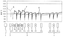
上記供試材を加熱炉内にて加熱したのち、仕上圧延後の直径が9.5mmとなるようにパススケジュールをとったときの表面温度推移を図2に示す。図2において、細線6は、比較例であり、鋼片加熱炉での抽出温度を1130℃とし、加熱炉抽出後は、誘導加熱装置等で鋼材を加熱しなかった例である。この比較例では、鋼材の圧延最低温度は、1000℃を下回っている。図2において、太線7は、発明例であり、鋼片加熱炉での抽出温度は、比較例と同じくし、粗圧延機列での第1圧延機と第2圧延機の間、第2圧延機と第3圧延機の間、および第3圧延機と第4圧延機の間に設けたそれぞれの誘導加熱装置(5a、5b、5c)により鋼材を加熱した例である。この発明例では、鋼材の圧延最低温度は、1000℃を上回っている。比較例と発明例における、熱間圧延後の鋼材の表面疵による不良率を表2に示す。表2に示すとおり、発明例の表面疵不良率は、比較例よりも低減されていることがわかる。
<Example 1>
FIG. 2 shows the change in surface temperature when the sample material is heated in a heating furnace and then a pass schedule is taken so that the diameter after finish rolling is 9.5 mm. In FIG. 2, the
<実施例2>
上記供試材を加熱炉内にて加熱したのち、仕上圧延後の直径が5.5mmとなるようにパススケジュールをとったときの表面温度推移を図3に示す。図3において、細線6は、比較例であり、鋼片加熱炉での抽出温度を1210℃とし、加熱炉抽出後は、誘導加熱装置等で鋼材を加熱しなかった例である。この比較例では、鋼材の圧延最低温度は、1000℃を下回っている。図3において、太線8は、発明例1であり、鋼片加熱炉での抽出温度は、比較例と同じくし、実施例1と同様に設けた誘導加熱装置により鋼材を加熱した例である。この発明例1では、鋼材の圧延最低温度は、1000℃を上回っている。図3おいて、点線9は、発明例2であり、鋼片加熱炉での抽出温度は1160℃とし、誘導加熱装置の出力をアップして誘導加熱以降の圧延温度推移を発明例1と同じくした例である。比較例と発明例1、2における、熱間圧延後の鋼材の表面疵による不良率を表3に示す。
表3に示すとおり、発明例1の表面疵不良率は、比較例より低減しており、発明例2では、さらに低減している。
<Example 2>
FIG. 3 shows the transition of the surface temperature when the test material is heated in a heating furnace and the pass schedule is taken so that the diameter after finish rolling is 5.5 mm. In FIG. 3, a
As shown in Table 3, the surface defect rate of Invention Example 1 is lower than that of Comparative Example, and in Invention Example 2, it is further reduced.
実施例1、2に示すように、硫黄含有快削鋼においては、圧延最低温度が1000℃を下回ると延性不足により、1200℃を超えると粗大粒起因により、表面疵が著しく増加するが、粗圧延機列の最上流側で誘導加熱を行い、圧延最低温度を高めて1000℃以上とすることにより表面疵が低減し、さらには、加熱炉抽出温度を低下させることにより、さらに表面疵を低減させることができる。
尚、上記実施例は、硫黄含有快削鋼における実施例であるが、本発明は、上記実施例に限定されるものではない。
As shown in Examples 1 and 2, in the sulfur-containing free-cutting steel, when the minimum rolling temperature is below 1000 ° C., the ductility is insufficient, and when it exceeds 1200 ° C., the surface flaws are remarkably increased due to coarse grains. Induction heating is performed on the uppermost stream side of the rolling mill row, the surface flaw is reduced by raising the rolling minimum temperature to 1000 ° C or higher, and further reducing the flaw extraction temperature by lowering the heating furnace extraction temperature. Can be made.
In addition, although the said Example is an Example in sulfur containing free cutting steel, this invention is not limited to the said Example.
1:加熱炉
2:デスケーラー
3:粗圧延機列
4:中間圧延機列
5a、5b、5c:誘導加熱装置
#1〜#11:圧延機No.
1: Heating furnace 2: Descaler 3: Rough rolling mill row 4: Intermediate rolling
Claims (6)
Priority Applications (1)
| Application Number | Priority Date | Filing Date | Title |
|---|---|---|---|
| JP2007052288A JP2008212965A (en) | 2007-03-02 | 2007-03-02 | Method and equipment for hot-rolling steel bar or wire rod |
Applications Claiming Priority (1)
| Application Number | Priority Date | Filing Date | Title |
|---|---|---|---|
| JP2007052288A JP2008212965A (en) | 2007-03-02 | 2007-03-02 | Method and equipment for hot-rolling steel bar or wire rod |
Publications (1)
| Publication Number | Publication Date |
|---|---|
| JP2008212965A true JP2008212965A (en) | 2008-09-18 |
Family
ID=39833634
Family Applications (1)
| Application Number | Title | Priority Date | Filing Date |
|---|---|---|---|
| JP2007052288A Pending JP2008212965A (en) | 2007-03-02 | 2007-03-02 | Method and equipment for hot-rolling steel bar or wire rod |
Country Status (1)
| Country | Link |
|---|---|
| JP (1) | JP2008212965A (en) |
Cited By (2)
| Publication number | Priority date | Publication date | Assignee | Title |
|---|---|---|---|---|
| CN103736727A (en) * | 2013-12-27 | 2014-04-23 | 西安建筑科技大学 | TC16 titanium alloy bar temperature control continuous rolling method |
| CN104174649A (en) * | 2014-07-21 | 2014-12-03 | 攀钢集团攀枝花钢铁研究院有限公司 | Method for producing titanium and titanium alloy wires through hot continuous rolling |
Citations (4)
| Publication number | Priority date | Publication date | Assignee | Title |
|---|---|---|---|---|
| JPH0299204A (en) * | 1988-09-30 | 1990-04-11 | Daido Steel Co Ltd | Method for continuous rolling |
| JP2001009504A (en) * | 1999-06-30 | 2001-01-16 | Hitachi Metals Ltd | Thin wire rolling method and equipment |
| JP2001300623A (en) * | 2000-04-25 | 2001-10-30 | Nippon Steel Corp | Outlet guide of rolling mill on hot-rolling line for bar and wire |
| JP2004001041A (en) * | 2002-05-31 | 2004-01-08 | Kobe Steel Ltd | Method for hot rolling wire rod and steel bar |
-
2007
- 2007-03-02 JP JP2007052288A patent/JP2008212965A/en active Pending
Patent Citations (4)
| Publication number | Priority date | Publication date | Assignee | Title |
|---|---|---|---|---|
| JPH0299204A (en) * | 1988-09-30 | 1990-04-11 | Daido Steel Co Ltd | Method for continuous rolling |
| JP2001009504A (en) * | 1999-06-30 | 2001-01-16 | Hitachi Metals Ltd | Thin wire rolling method and equipment |
| JP2001300623A (en) * | 2000-04-25 | 2001-10-30 | Nippon Steel Corp | Outlet guide of rolling mill on hot-rolling line for bar and wire |
| JP2004001041A (en) * | 2002-05-31 | 2004-01-08 | Kobe Steel Ltd | Method for hot rolling wire rod and steel bar |
Cited By (4)
| Publication number | Priority date | Publication date | Assignee | Title |
|---|---|---|---|---|
| CN103736727A (en) * | 2013-12-27 | 2014-04-23 | 西安建筑科技大学 | TC16 titanium alloy bar temperature control continuous rolling method |
| CN103736727B (en) * | 2013-12-27 | 2015-12-30 | 西安建筑科技大学 | A kind of TC16 titanium alloy rod bar temperature control method for tandem rolling |
| CN104174649A (en) * | 2014-07-21 | 2014-12-03 | 攀钢集团攀枝花钢铁研究院有限公司 | Method for producing titanium and titanium alloy wires through hot continuous rolling |
| CN104174649B (en) * | 2014-07-21 | 2016-01-20 | 攀钢集团攀枝花钢铁研究院有限公司 | Hot continuous rolling produces the method for titanium or titanium alloy wire rod |
Similar Documents
| Publication | Publication Date | Title |
|---|---|---|
| JP4513807B2 (en) | Fe-Ni alloy tube and method of manufacturing the same | |
| JP2008212965A (en) | Method and equipment for hot-rolling steel bar or wire rod | |
| JP2008019480A (en) | Method for manufacturing steel pipe, and facility line for manufacturing steel pipe | |
| JP4415914B2 (en) | Method for producing hot-rolled steel sheet having fine ferrite structure | |
| RU2011119637A (en) | METHOD AND DEVICE FOR MANUFACTURING A HOT-ROLLED SILICON STEEL STRIP | |
| CN113102526A (en) | Rolling process of C45 round steel | |
| JP5009520B2 (en) | Method for producing Fe-Cr martensitic stainless steel bar | |
| CN113102527A (en) | Rolling process of 45Mn2 round steel | |
| JP5632624B2 (en) | Steel bar manufacturing method | |
| JP3374757B2 (en) | Manufacturing method of steel sheet with excellent surface properties | |
| KR101696113B1 (en) | Wire rod enabling omitting heat treatment, method for manufacturing same and method for manufacturing steel wire using the same | |
| JP4670538B2 (en) | Method for producing hot-rolled steel sheet having fine ferrite structure | |
| JP3796209B2 (en) | Hot rolling method for austenitic stainless steel pieces | |
| JP5854177B1 (en) | Hot rolling method for high carbon steel | |
| JP5935541B2 (en) | Manufacturing method of hot-rolled steel sheet | |
| CN115491592B (en) | 20MnCr5 gear steel and rolling method thereof | |
| JP4305207B2 (en) | Method for producing hot-rolled steel sheet having fine ferrite structure | |
| JP2009255107A (en) | Method of preventing crack in rolling caused by change of set temperature of heating furnace in 18-8 stainless steel | |
| JP2010005659A (en) | Method of manufacturing magnesium sheet | |
| JP6617858B1 (en) | Ferritic stainless steel sheet and manufacturing method thereof | |
| JP4586479B2 (en) | Manufacturing method of high-tensile cold-rolled steel sheet in continuous annealing process | |
| JP2015131311A (en) | Method of hot-working steel material excellent in surface quality | |
| JP2007330984A (en) | Method of hot-rolling steel | |
| JP4935461B2 (en) | Manufacturing method and manufacturing equipment for hot rolled steel sheet | |
| JP2705411B2 (en) | Manufacturing method of high toughness ferritic stainless steel strip |
Legal Events
| Date | Code | Title | Description |
|---|---|---|---|
| A621 | Written request for application examination |
Free format text: JAPANESE INTERMEDIATE CODE: A621 Effective date: 20090217 |
|
| A977 | Report on retrieval |
Free format text: JAPANESE INTERMEDIATE CODE: A971007 Effective date: 20110304 |
|
| A131 | Notification of reasons for refusal |
Free format text: JAPANESE INTERMEDIATE CODE: A131 Effective date: 20110607 |
|
| A521 | Written amendment |
Free format text: JAPANESE INTERMEDIATE CODE: A523 Effective date: 20110729 |
|
| A02 | Decision of refusal |
Free format text: JAPANESE INTERMEDIATE CODE: A02 Effective date: 20110816 |