JP2008209654A - Optical communication system - Google Patents
Optical communication system Download PDFInfo
- Publication number
- JP2008209654A JP2008209654A JP2007046255A JP2007046255A JP2008209654A JP 2008209654 A JP2008209654 A JP 2008209654A JP 2007046255 A JP2007046255 A JP 2007046255A JP 2007046255 A JP2007046255 A JP 2007046255A JP 2008209654 A JP2008209654 A JP 2008209654A
- Authority
- JP
- Japan
- Prior art keywords
- optical fiber
- optical
- value
- communication system
- dispersion
- Prior art date
- Legal status (The legal status is an assumption and is not a legal conclusion. Google has not performed a legal analysis and makes no representation as to the accuracy of the status listed.)
- Pending
Links
Images


Classifications
-
- G—PHYSICS
- G02—OPTICS
- G02B—OPTICAL ELEMENTS, SYSTEMS OR APPARATUS
- G02B6/00—Light guides; Structural details of arrangements comprising light guides and other optical elements, e.g. couplings
- G02B6/02—Optical fibres with cladding with or without a coating
- G02B6/036—Optical fibres with cladding with or without a coating core or cladding comprising multiple layers
- G02B6/03616—Optical fibres characterised both by the number of different refractive index layers around the central core segment, i.e. around the innermost high index core layer, and their relative refractive index difference
- G02B6/03622—Optical fibres characterised both by the number of different refractive index layers around the central core segment, i.e. around the innermost high index core layer, and their relative refractive index difference having 2 layers only
- G02B6/03627—Optical fibres characterised both by the number of different refractive index layers around the central core segment, i.e. around the innermost high index core layer, and their relative refractive index difference having 2 layers only arranged - +
-
- G—PHYSICS
- G02—OPTICS
- G02B—OPTICAL ELEMENTS, SYSTEMS OR APPARATUS
- G02B6/00—Light guides; Structural details of arrangements comprising light guides and other optical elements, e.g. couplings
- G02B6/02—Optical fibres with cladding with or without a coating
- G02B6/02004—Optical fibres with cladding with or without a coating characterised by the core effective area or mode field radius
- G02B6/02009—Large effective area or mode field radius, e.g. to reduce nonlinear effects in single mode fibres
- G02B6/02014—Effective area greater than 60 square microns in the C band, i.e. 1530-1565 nm
- G02B6/02019—Effective area greater than 90 square microns in the C band, i.e. 1530-1565 nm
-
- G—PHYSICS
- G02—OPTICS
- G02B—OPTICAL ELEMENTS, SYSTEMS OR APPARATUS
- G02B6/00—Light guides; Structural details of arrangements comprising light guides and other optical elements, e.g. couplings
- G02B6/02—Optical fibres with cladding with or without a coating
- G02B6/02214—Optical fibres with cladding with or without a coating tailored to obtain the desired dispersion, e.g. dispersion shifted, dispersion flattened
- G02B6/0228—Characterised by the wavelength dispersion slope properties around 1550 nm
-
- G—PHYSICS
- G02—OPTICS
- G02B—OPTICAL ELEMENTS, SYSTEMS OR APPARATUS
- G02B6/00—Light guides; Structural details of arrangements comprising light guides and other optical elements, e.g. couplings
- G02B6/02—Optical fibres with cladding with or without a coating
- G02B6/02295—Microstructured optical fibre
- G02B6/02314—Plurality of longitudinal structures extending along optical fibre axis, e.g. holes
- G02B6/02342—Plurality of longitudinal structures extending along optical fibre axis, e.g. holes characterised by cladding features, i.e. light confining region
-
- G—PHYSICS
- G02—OPTICS
- G02B—OPTICAL ELEMENTS, SYSTEMS OR APPARATUS
- G02B6/00—Light guides; Structural details of arrangements comprising light guides and other optical elements, e.g. couplings
- G02B6/24—Coupling light guides
- G02B6/26—Optical coupling means
- G02B6/28—Optical coupling means having data bus means, i.e. plural waveguides interconnected and providing an inherently bidirectional system by mixing and splitting signals
- G02B6/293—Optical coupling means having data bus means, i.e. plural waveguides interconnected and providing an inherently bidirectional system by mixing and splitting signals with wavelength selective means
- G02B6/29371—Optical coupling means having data bus means, i.e. plural waveguides interconnected and providing an inherently bidirectional system by mixing and splitting signals with wavelength selective means operating principle based on material dispersion
- G02B6/29374—Optical coupling means having data bus means, i.e. plural waveguides interconnected and providing an inherently bidirectional system by mixing and splitting signals with wavelength selective means operating principle based on material dispersion in an optical light guide
- G02B6/29376—Optical coupling means having data bus means, i.e. plural waveguides interconnected and providing an inherently bidirectional system by mixing and splitting signals with wavelength selective means operating principle based on material dispersion in an optical light guide coupling light guides for controlling wavelength dispersion, e.g. by concatenation of two light guides having different dispersion properties
- G02B6/29377—Optical coupling means having data bus means, i.e. plural waveguides interconnected and providing an inherently bidirectional system by mixing and splitting signals with wavelength selective means operating principle based on material dispersion in an optical light guide coupling light guides for controlling wavelength dispersion, e.g. by concatenation of two light guides having different dispersion properties controlling dispersion around 1550 nm, i.e. S, C, L and U bands from 1460-1675 nm
-
- G—PHYSICS
- G02—OPTICS
- G02B—OPTICAL ELEMENTS, SYSTEMS OR APPARATUS
- G02B6/00—Light guides; Structural details of arrangements comprising light guides and other optical elements, e.g. couplings
- G02B6/02—Optical fibres with cladding with or without a coating
- G02B6/02214—Optical fibres with cladding with or without a coating tailored to obtain the desired dispersion, e.g. dispersion shifted, dispersion flattened
- G02B6/02219—Characterised by the wavelength dispersion properties in the silica low loss window around 1550 nm, i.e. S, C, L and U bands from 1460-1675 nm
- G02B6/02252—Negative dispersion fibres at 1550 nm
- G02B6/02261—Dispersion compensating fibres, i.e. for compensating positive dispersion of other fibres
-
- G—PHYSICS
- G02—OPTICS
- G02B—OPTICAL ELEMENTS, SYSTEMS OR APPARATUS
- G02B6/00—Light guides; Structural details of arrangements comprising light guides and other optical elements, e.g. couplings
- G02B6/24—Coupling light guides
- G02B6/26—Optical coupling means
- G02B6/28—Optical coupling means having data bus means, i.e. plural waveguides interconnected and providing an inherently bidirectional system by mixing and splitting signals
- G02B6/293—Optical coupling means having data bus means, i.e. plural waveguides interconnected and providing an inherently bidirectional system by mixing and splitting signals with wavelength selective means
- G02B6/29304—Optical coupling means having data bus means, i.e. plural waveguides interconnected and providing an inherently bidirectional system by mixing and splitting signals with wavelength selective means operating by diffraction, e.g. grating
- G02B6/29316—Light guides comprising a diffractive element, e.g. grating in or on the light guide such that diffracted light is confined in the light guide
- G02B6/29317—Light guides of the optical fibre type
-
- G—PHYSICS
- G02—OPTICS
- G02B—OPTICAL ELEMENTS, SYSTEMS OR APPARATUS
- G02B6/00—Light guides; Structural details of arrangements comprising light guides and other optical elements, e.g. couplings
- G02B6/24—Coupling light guides
- G02B6/26—Optical coupling means
- G02B6/28—Optical coupling means having data bus means, i.e. plural waveguides interconnected and providing an inherently bidirectional system by mixing and splitting signals
- G02B6/293—Optical coupling means having data bus means, i.e. plural waveguides interconnected and providing an inherently bidirectional system by mixing and splitting signals with wavelength selective means
- G02B6/29379—Optical coupling means having data bus means, i.e. plural waveguides interconnected and providing an inherently bidirectional system by mixing and splitting signals with wavelength selective means characterised by the function or use of the complete device
- G02B6/29392—Controlling dispersion
- G02B6/29394—Compensating wavelength dispersion
Abstract
Description
本発明は、光伝送路として光ファイバを用いた光通信システムに関するものである。 The present invention relates to an optical communication system using an optical fiber as an optical transmission line.
ハイパワー光の伝送に代表される非通信用として、フォトニックバンドギャップ光ファイバ(Photonic BandGap Fiber,PBGF)の使用が盛んに検討されている。フォトニックバンドギャップ光ファイバとは、クラッド部にこのクラッド部とは屈折率が異なる空気などの媒質を周期的に配列してブラッグ回折格子を形成し、前記クラッド部内に設けた空孔をコアとして前記ブラック回折格子が形成するフォトニックバンドギャップ内の所定の使用波長の光を伝搬するものである。このフォトニックバンドギャップ光ファイバに関しては、非特許文献1に示されるように、商用ベースでの紹介がなされている。
As non-communications typified by transmission of high-power light, use of a photonic bandgap optical fiber (Photonic Bandgap Fiber, PBGF) has been actively studied. A photonic bandgap optical fiber is a Bragg diffraction grating formed by periodically arranging a medium such as air having a refractive index different from that of the cladding part in the cladding part, and the holes provided in the cladding part are used as cores. It propagates light of a predetermined use wavelength within the photonic band gap formed by the black diffraction grating. The photonic bandgap optical fiber has been introduced on a commercial basis as shown in Non-Patent
一方、フォトニックバンドギャップ現象を用いない穴あき系光ファイバ(Microstructure Optical Fiber,MOF)であるホーリーファイバ、あるいはフォトニッククリスタル光ファイバ(Potonic Crystal Fiber,PCF)に関しては、その広帯域伝送ポテンシャルなどから、通信用としての使用可能性が盛んに議論されている。たとえば非特許文献2では、PCFと分散補償光ファイバ(Dispersion Compensating Fiber,DCF)とを組み合わせて、長さ100kmにおよぶ光伝送路を用いた伝送速度が10Gb/sの分散マネージメントソリトンの伝送特性を報告している。
On the other hand, for holey optical fibers (Microstructure Optical Fiber, MOF) that do not use the photonic bandgap phenomenon, or photonic crystal optical fibers (Photonic Crystal Fiber, PCF), because of their broadband transmission potential, The possibility of use for communication is actively discussed. For example, in Non-Patent
ところで、前記のフォトニックバンドギャップ光ファイバに関しても、低光学非線形性や低伝送損失ポテンシャルを有することから、通信用として大きな魅力がある。 By the way, the photonic bandgap optical fiber is also attractive for communication because of its low optical nonlinearity and low transmission loss potential.
しかしながら、非特許文献1に示されるように、フォトニックバンドギャップ光ファイバは、通信に使用する光信号の波長である使用波長において、大きな波長分散値と分散スロープ値とを有し、波長分散値を分散スロープ値で除算したD/S値が極めて小さい。その結果、フォトニックバンドギャップ光ファイバを用いて光伝送路を構成した場合、従来の分散補償光ファイバなどの分散補償器を用いても波長分散と分散スロープとを補償できず、長距離かつ広帯域の光信号伝送ができないという問題があった。
However, as shown in Non-Patent
本発明は、上記に鑑みてなされたものであって、フォトニックバンドギャップ光ファイバの低光学非線形性と低伝送損失特性とを活用しながら、光伝送路の波長分散特性を容易に補償できる光通信システムを提供することを目的とする。 The present invention has been made in view of the above, and is an optical device that can easily compensate for the chromatic dispersion characteristic of an optical transmission line while utilizing the low optical nonlinearity and low transmission loss characteristic of a photonic bandgap optical fiber. An object is to provide a communication system.
上述した課題を解決し、目的を達成するために、本発明に係る光通信システムは、光伝送路として光ファイバを用いた光通信システムであって、前記光伝送路は、中心に位置し、空孔が構成するコアと、前記コアの外側に位置する外側クラッドと、前記コアと前記外側クラッドの間に位置し、該外側クラッドとは屈折率が異なる媒質を周期的に配列してブラッグ回折格子を形成した内側クラッドと、を有し、前記ブラック回折格子が形成するフォトニックバンドギャップ内の所定の使用波長の光を伝搬するフォトニックバンドギャップ光ファイバと、前記フォトニックバンドギャップ光ファイバに隣接して接続し、前記使用波長において前記フォトニックバンドギャップ光ファイバの波長分散値よりも小さく0ps/nm/km以上の波長分散値を有するとともに波長分散値を分散スロープ値で除算したD/S値が該フォトニックバンドギャップ光ファイバのD/S値よりも大きい光ファイバと、を備えることを特徴とする。 In order to solve the above-described problems and achieve the object, an optical communication system according to the present invention is an optical communication system using an optical fiber as an optical transmission line, and the optical transmission line is located at the center, Bragg diffraction by periodically arranging a core formed by holes, an outer clad positioned outside the core, and a medium positioned between the core and the outer clad and having a refractive index different from that of the outer clad. A photonic bandgap optical fiber that propagates light of a predetermined use wavelength within the photonic bandgap formed by the black diffraction grating, and the photonic bandgap optical fiber. Connected adjacent to each other, and a wavelength component of 0 ps / nm / km or more smaller than the chromatic dispersion value of the photonic band gap optical fiber at the used wavelength. D / S value of the chromatic dispersion value is divided by the dispersion slope which has a value which is characterized in that and a optical fiber is greater than D / S value of the photonic bandgap fiber.
また、本発明に係る光通信システムは、上記の発明において、前記光ファイバは、前記使用波長において、25ps/nm/km以下の波長分散値と100nm以上のD/S値とを有することを特徴とする。 In the optical communication system according to the present invention as set forth in the invention described above, the optical fiber has a chromatic dispersion value of 25 ps / nm / km or less and a D / S value of 100 nm or more at the used wavelength. And
また、本発明に係る光通信システムは、上記の発明において、前記光伝送路は、前記フォトニックバンドギャップ光ファイバまたは前記光ファイバに隣接して接続し、前記使用波長において前記フォトニックバンドギャップ光ファイバと前記光ファイバとの波長分散の総和および平均分散スロープを補償する負の波長分散値および分散スロープ値を有する分散補償器を備えることを特徴とする。 The optical communication system according to the present invention is the optical communication system according to the above invention, wherein the optical transmission line is connected adjacent to the photonic band gap optical fiber or the optical fiber, and the photonic band gap light is used at the used wavelength. A dispersion compensator having a negative chromatic dispersion value and a dispersion slope value for compensating for the total chromatic dispersion and the average dispersion slope of the fiber and the optical fiber is provided.
また、本発明に係る光通信システムは、上記の発明において、前記分散補償器は、前記フォトニックバンドギャップ光ファイバと前記光ファイバとの平均D/S値の70〜130%のD/S値を有することを特徴とする。 In the optical communication system according to the present invention, the dispersion compensator is a D / S value that is 70 to 130% of an average D / S value of the photonic bandgap optical fiber and the optical fiber. It is characterized by having.
また、本発明に係る光通信システムは、上記の発明において、前記使用波長は、800〜1700nmであることを特徴とする。 The optical communication system according to the present invention is characterized in that, in the above-mentioned invention, the wavelength used is 800 to 1700 nm.
また、本発明に係る光通信システムは、上記の発明において、前記使用波長は、1530〜1625nmであることを特徴とする。 The optical communication system according to the present invention is characterized in that, in the above invention, the wavelength used is 1530 to 1625 nm.
また、本発明に係る光通信システムは、上記の発明において、前記光ファイバは、中心コア部と、前記中心コア部の外周に形成され前記中心コア部よりも屈折率が低い外側コア層と、前記外側コア層の外周に形成され前記中心コア部よりも屈折率が低くかつ前記外側コア層よりも屈折率が高いクラッド層と、を有し、波長1500nmにおいて、波長分散値が25ps/nm/km以下であり、D/S値が300nm以上であり、有効コア断面積が80μm2以上であり、伝送損失が0.25dB/km以下であることを特徴とする。 Further, in the optical communication system according to the present invention, in the above invention, the optical fiber includes a central core portion, an outer core layer formed on an outer periphery of the central core portion and having a lower refractive index than the central core portion, A cladding layer formed on the outer periphery of the outer core layer and having a refractive index lower than that of the central core portion and higher than that of the outer core layer, and having a wavelength dispersion value of 25 ps / nm / at a wavelength of 1500 nm. It is not more than km, D / S value is not less than 300 nm, effective core area is not less than 80 μm 2 , and transmission loss is not more than 0.25 dB / km.
また、本発明に係る光通信システムは、上記の発明において、前記光ファイバは、中心コア部と、前記中心コア部の外周に形成され前記中心コア部よりも屈折率が低い外側コア層と、前記外側コア層の外周に形成され前記中心コア部よりも屈折率が低くかつ前記外側コア層よりも屈折率が高いクラッド層と、を有し、前記中心コア部の前記クラッド層に対する比屈折率差Δ1が0.15〜0.4%であり、前記外側コア層の前記クラッド層に対する比屈折率差Δ2が−0.35〜−0.05%であり、前記中心コア部の直径に対する前記外側コア層の外径の比b/aが1.5〜6であることを特徴とする。 Further, in the optical communication system according to the present invention, in the above invention, the optical fiber includes a central core portion, an outer core layer formed on an outer periphery of the central core portion and having a lower refractive index than the central core portion, A clad layer formed on an outer periphery of the outer core layer and having a refractive index lower than that of the central core portion and higher than that of the outer core layer, and a relative refractive index of the central core portion with respect to the cladding layer The difference Δ1 is 0.15 to 0.4%, the relative refractive index difference Δ2 of the outer core layer to the cladding layer is −0.35 to −0.05%, and the diameter relative to the diameter of the central core portion is The outer core layer has an outer diameter ratio b / a of 1.5 to 6.
また、本発明に係る光通信システムは、上記の発明において、前記分散補償器は、前記使用波長において、−80ps/nm/km以下の波長分散値を有することを特徴とする。 In the optical communication system according to the present invention as set forth in the invention described above, the dispersion compensator has a chromatic dispersion value of −80 ps / nm / km or less at the used wavelength.
本発明に係る光通信システムは、光伝送路が、フォトニックバンドギャップ光ファイバと、フォトニックバンドギャップ光ファイバの波長分散値よりも小さく0ps/nm/km以上の波長分散値を有するとともに波長分散値を分散スロープ値で除算したD/S値が該フォトニックバンドギャップ光ファイバのD/S値よりも大きい光ファイバとを備えることにより、フォトニックバンドギャップ光ファイバが極めて小さいD/S値を有していても、光伝送路の波長分散の総和および平均分散スロープが大幅に小さくなるので、フォトニックバンドギャップ光ファイバの低光学非線形性と低伝送損失特性とを活用しながら、光伝送路の波長分散特性を容易に補償できるという効果を奏する。 In the optical communication system according to the present invention, the optical transmission line has a chromatic dispersion value that is smaller than the chromatic dispersion value of the photonic band gap optical fiber and the photonic band gap optical fiber and is 0 ps / nm / km or more. By providing an optical fiber having a D / S value obtained by dividing the value by the dispersion slope value larger than the D / S value of the photonic band gap optical fiber, the photonic band gap optical fiber has an extremely small D / S value. Even if the optical transmission line is included, the total chromatic dispersion and the average dispersion slope of the optical transmission line are greatly reduced, so that the optical transmission line can be utilized while utilizing the low optical nonlinearity and low transmission loss characteristics of the photonic bandgap optical fiber. It is possible to easily compensate for the chromatic dispersion characteristics.
以下に、図面を参照して本発明に係る光通信システムの実施の形態を詳細に説明する。なお、この実施の形態によりこの発明が限定されるものではない。また、以下ではフォトニックバンドギャップ光ファイバをPBGF、分散補償光ファイバをDCFと記載する。また、本明細書においては、カットオフ波長(λc)とは、ITU−T(国際電気通信連合)G.650.1で定義するファイバカットオフ波長をいう。その他、本明細書で特に定義しない用語についてはITU−T G.650.1における定義、測定方法に従うものとする。 Embodiments of an optical communication system according to the present invention will be described below in detail with reference to the drawings. Note that the present invention is not limited to the embodiments. Hereinafter, the photonic band gap optical fiber is referred to as PBGF, and the dispersion compensating optical fiber is referred to as DCF. In this specification, the cutoff wavelength (λ c ) is ITU-T (International Telecommunication Union) This refers to the fiber cutoff wavelength defined in 650.1. For other terms not specifically defined in this specification, see ITU-T G.C. It shall follow the definition and measurement method in 650.1.
(実施の形態)
図1は、本発明の実施の形態に係る光通信システムのブロック図である。図1に示すように、本実施の形態に係る光通信システム10は、光信号を送信する光送信器5と、光送信器5が送信した光信号を再生中継する光中継器7−1〜7−n−1と、光信号を受信する光受信器6と、光送信器5と光中継器7−1〜7−n−1と光受信器6とを接続して光信号を伝送する光伝送路4−1〜4−nとを備える。なお、nは、2以上の整数である。
(Embodiment)
FIG. 1 is a block diagram of an optical communication system according to an embodiment of the present invention. As shown in FIG. 1, an
光伝送路4−1〜4−nは、PBGF1−1〜1−nと、PBGF1−1〜1−nに接続点C−1〜C−nにおいて接続する光ファイバ2−1〜2−nと、光ファイバ2−1〜2−nに隣接して接続する分散補償器3−1〜3−nとを備える。なお、光伝送路4−1〜4−nのPBGF1−1〜1−n、光ファイバ2−1〜2−n、分散補償器3−1〜3−n以外の部分は標準のシングルモード光ファイバなどからなる。 The optical transmission lines 4-1 to 4-n are PBGF 1-1 to 1-n and optical fibers 2-1 to 2-n connected to the PBGF 1-1 to 1-n at connection points C-1 to C-n. And dispersion compensators 3-1 to 3-n connected adjacent to the optical fibers 2-1 to 2-n. The portions other than the PBGF 1-1 to 1-n, the optical fibers 2-1 to 2-n, and the dispersion compensators 3-1 to 3-n of the optical transmission lines 4-1 to 4-n are standard single mode light. It consists of fiber.
図2は、本実施の形態に係るPBGF1を模式的に示した断面図である。なお、PBGF1−1〜1−nは、いずれもPBGF1と同様のものである。このPBGF1は、非特許文献1に開示されたものと同様のものであり、外側クラッド部11と、この外側クラッド部11とは屈折率が異なる媒質である微細な空孔を周期的に配列してブラッグ回折格子を形成した内側クラッド部12とを有し、PBGF1の中心部付近に空孔が構成するコア13を設け、ブラック回折格子が形成するフォトニックバンドギャップ内の使用波長の光を伝搬する。この使用波長は、たとえばブラック回折格子が形成するフォトニックバンドギャップの中心波長である1550nmである。また、PBGF1は使用波長1550nmにおいて50ps/nm/km以上の大きな波長分散値を有するとともに、0.5ps/nm2/km以上の大きな分散スロープ値を有する。
FIG. 2 is a cross-sectional view schematically showing
一方、光ファイバ2−1〜2−nは、使用波長1550nmにおいて、PBGF1−1〜1−nの波長分散値よりも小さく0ps/nm/km以上の波長分散値を有するとともに、波長分散値を分散スロープ値で除算したD/S値がPBGF1−1〜1−nのD/S値よりも大きいものである。したがって、光伝送路4−1〜4−nは、光伝送路4−1〜4−nと同一の長さの光伝送路をPBGFのみで構成した場合よりも波長分散の総和が大幅に小さくなり、D/S値が大幅に大きくなる。 On the other hand, the optical fibers 2-1 to 2-n have a chromatic dispersion value of 0 ps / nm / km or more smaller than the chromatic dispersion value of the PBGF 1-1 to 1-n at the used wavelength of 1550 nm, and have a chromatic dispersion value. The D / S value divided by the dispersion slope value is larger than the D / S values of PBGF 1-1 to 1-n. Therefore, the total of chromatic dispersion is significantly smaller in the optical transmission lines 4-1 to 4-n than in the case where the optical transmission lines having the same length as the optical transmission lines 4-1 to 4-n are configured by only PBGF. Thus, the D / S value is significantly increased.
以下、光ファイバ2−1〜2−nについてさらに詳細に説明する。図3は、本発明の実施の形態に係る光ファイバ2を模式的に示した断面図である。なお、光ファイバ2−1〜2−nは、いずれも光ファイバ2と同様のものである。この光ファイバ2は、中心コア部21と、中心コア部21の外周に形成され中心コア部21よりも屈折率が低い外側コア層22と、外側コア層22の外周に形成され中心コア部21よりも屈折率が低くかつ外側コア層22よりも屈折率が高いクラッド層23とを有する。
Hereinafter, the optical fibers 2-1 to 2-n will be described in more detail. FIG. 3 is a cross-sectional view schematically showing the
そして、屈折率プロファイルに関しては、中心コア部21のクラッド層23に対する比屈折率差Δ1が0.15〜0.4%であり、外側コア層22のクラッド層23に対する比屈折率差Δ2が−0.35〜−0.05%であり、中心コア部21の直径2aに対する外側コア層22の外径2bの比b/aが1.5〜6である。その結果、光ファイバ2は、波長分散値が0ps/nm/km以上25ps/nm/km以下となり、D/S値が100nm以上、特には300nm以上となり、有効コア断面積が80μm2以上となるので、光伝送路4−1〜4−nの波長分散の総和を低減し、D/S値を大きくするとともに、光学非線形性が小さいものとなる。また、伝送損失も容易に0.25dB/kmとできる。
Regarding the refractive index profile, the relative refractive index difference Δ1 of the
また、光ファイバ2は、Δ1が上記の範囲にあるので、有効コア断面積が上記の値になるとともに曲げ損失が十分小さくなり、Δ2が上記の範囲にあるので、波長分散値および分散スロープ値が上記の値になるとともに曲げ損失が十分小さくなり、b/aが上記の範囲にあるので、GeやFなどの屈折率調整用のドーパントの添加量に伴う製造コストの上昇を抑制できるとともに曲げ損失が十分小さくなる。
In addition, since the
一方、図4は、本実施の形態に係る分散補償器3の構成を模式的に示したブロック図である。なお、分散補償器3−1〜3−nは、いずれも分散補償器3と同様のものである。この分散補償器3は、ファイバ型分散補償器であって、DCF31は接続点32、33を介して光伝送路4と接続している。
On the other hand, FIG. 4 is a block diagram schematically showing the configuration of the
本実施の形態に係る分散補償器3は、PBGF1と光ファイバ2との波長分散の総和および平均分散スロープを補償する負の波長分散値および分散スロープ値を有する。ここで、上述のように、光伝送路をPBGF1のみで構成した場合と比較して、PBGF1と光ファイバ2との波長分散の総和は、大幅に小さく、D/S値は大幅に大きくなっている。したがって、分散補償器3として、たとえば従来の標準のシングルモード光ファイバ(SMF)からなる光伝送路の分散補償に用いられる、使用波長における波長分散値が−80〜−180ps/nm/km程度であり、D/Sが250nm〜350nm程度の分散補償器を用いて、容易かつ十分に分散補償ができる。したがって、この光通信システム10は、PBGF1−1〜1−nの低光学非線形性と低伝送損失特性を活用しつつ、従来の安価な分散補償器によって波長分散および分散スロープが補償された、長距離かつ広帯域の光信号伝送ができるものとなる。
The
なお、光伝送路4−1〜4−nにおいて、光信号の強度は光送信器5または光中継器7−1〜7−nの出力部において最大であるから、光信号に非線形歪が発生することを回避するために、低光学非線形性のPBGF1−1〜1−nを光送信器5または光中継器7−1〜7−nの出力部側に配置することが好ましい。 In the optical transmission lines 4-1 to 4-n, since the intensity of the optical signal is maximum at the output part of the optical transmitter 5 or the optical repeaters 7-1 to 7-n, nonlinear distortion occurs in the optical signal. In order to avoid this, it is preferable to arrange the PBGF 1-1 to 1-n having low optical nonlinearity on the output side of the optical transmitter 5 or the optical repeaters 7-1 to 7-n.
以下、本実施の形態について、シミュレーション計算の結果を用いてさらに具体的に説明する。図5は、図3に示す光ファイバ2の光学特性の一例を示す図であり、図6は、図4に示すDCF31の光学特性の一例を示す図である。なお、図5においては、光ファイバ2のΔ1を0.3%、Δ2を−0.2%、b/aを4.0、2aを13.5μmとした。また、図5、6において、「D」は波長分散値を意味し、「Slope」は分散スロープ値を意味し、「MFD」はモードフィールド径を意味し、「Aeff」は有効コア断面積を意味し、「λc」はカットオフ波長を意味する。また、曲げ損失は、直径20mmで16ターン巻いたときの値である。
Hereinafter, the present embodiment will be described more specifically using the results of simulation calculation. FIG. 5 is a diagram illustrating an example of the optical characteristics of the
そして、図7は、図2に示すPBGF1と図3に示す光ファイバ2との長さの比を変えて構成した光伝送路の、波長1550nmにおける波長分散の総和、平均分散スロープ、平均D/S値について示す図である。なお、図7においては、PBGF1を、非特許文献1に開示されるような、中心波長1550nmにおいて波長分散値が97ps/nm/km、分散スロープ値が0.5ps/nm2/kmのものとした。また、「光伝送路1」〜「光伝送路3」はいずれも長さが100kmであるが、「光伝送路1」は、長さ100kmのPBGF1のみで構成した光伝送路であり、「光伝送路2」は、長さ50kmのPBGF1と長さ50kmの光ファイバ2とを用いて構成した光伝送路であり、「光伝送路3」は、長さ20kmのPBGF1と長さ80kmの光ファイバ2とを用いて構成した光伝送路である。図7に示すように、PBGF1と光ファイバ2とを用いた「光伝送路2」、「光伝送路3」は、波長分散の総和と平均分散スロープとが小さくなり、平均D/S値が大きくなるので、PBGF1のみからなる「光伝送路1」よりも分散補償が容易になる。
7 shows the sum of the chromatic dispersion, the average dispersion slope, the average D / D of the optical transmission line constructed by changing the length ratio between the
つぎに、図8は、図7に示す各光伝送路に図6に示すDCFを用いた分散補償器を接続した場合の、光伝送路の波長1550nmにおける波長分散の総和および平均分散スロープ、ならびにDCFの長さおよび伝送損失を示す図である。なお、各DCFは、各光伝送路の波長1550nmにおける波長分散値がゼロとなるような長さとした。図8に示すように、PBGF1と光ファイバ2とを備える「光伝送路2」、「光伝送路3」は、「光伝送路1」と比較して、残留する平均分散スロープ値が小さくなり、より広帯域の光信号伝送に適するものとなる。また、「光伝送路2」、「光伝送路3」は「光伝送路1」と比較して、必要なDCFの長さが短くなるので、伝送損失も22dB以下と小さくなり、たとえばエルビウム添加光ファイバ増幅器(EDFA)などの光増幅器を用いて容易に損失補償できる。
Next, FIG. 8 shows the sum and average dispersion slope of the chromatic dispersion at the
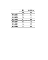
同様に、図9は、図2に示すPBGF1と図3に示す光ファイバ2との長さの比を変えて構成した光伝送路の、波長1570nmにおける波長分散の総和、平均分散スロープ、平均D/S値について示す図である。なお、図9において、PBGF1を、非特許文献1に開示されるような、中心波長1570nmにおいて波長分散値が50ps/nm/km、分散スロープ値が1.5ps/nm2/kmのものとした。また、「光伝送路4」〜「光伝送路6」はいずれも長さが100kmであるが、「光伝送路4」は、長さ100kmのPBGF1のみで構成した光伝送路であり、「光伝送路5」は、長さ50kmのPBGF1と長さ50kmの光ファイバ2とを用いて構成した光伝送路であり、「光伝送路6」は、長さ20kmのPBGF1と長さ80kmの光ファイバ2とを用いて構成した光伝送路である。図9に示すように、PBGF1と光ファイバ2とを用いた「光伝送路5」、「光伝送路6」は、波長分散の総和と平均分散スロープとが小さくなり、平均D/S値が大きくなるので、PBGF1のみからなる「光伝送路4」よりも分散補償が容易になる。
Similarly, FIG. 9 shows a sum of chromatic dispersion at a wavelength of 1570 nm, an average dispersion slope, and an average D of an optical transmission line configured by changing the length ratio between the
つぎに、図10は、図9に示す光伝送路に図6に示すDCFを用いた分散補償器を接続した場合の、光伝送路の波長1570nmにおける波長分散の総和および平均分散スロープ、ならびにDCFの長さおよび伝送損失を示す図である。なお、各DCFは、各伝送路の波長1570nmにおける波長分散値がゼロとなるような長さとした。図10に示すように、PBGF1と光ファイバ2とを備える「光伝送路5」、「光伝送路6」は、「光伝送路4」と比較して、残留する分散スロープ値が小さくなり、より広帯域の光信号伝送に適するものとなる。また、「光伝送路5」、「光伝送路6」は、「光伝送路4」と比較して、必要なDCFの長さが短くなるので、伝送損失も小さくなり、光増幅器を用いてより容易に損失補償できる。
Next, FIG. 10 shows the sum of the chromatic dispersion and the average dispersion slope at the
また、分散補償器に用いるDCFが、伝送損失に対して分散補償量の大きい、例えば、単位長さ当たりの分散の絶対値/伝送損失が350ps/nm/dB以上のいわゆる高FOM(Figure OF Merit)型のDCFであれば、よりDCFの長さを短くでき、伝送損失を小さくすることができる。 The DCF used in the dispersion compensator has a large dispersion compensation amount with respect to the transmission loss, for example, a so-called high FOM (Figure OF Merit) in which the absolute value of dispersion per unit length / transmission loss is 350 ps / nm / dB or more. ) Type DCF, the length of the DCF can be further shortened, and the transmission loss can be reduced.
図11は、図7、9に示す各光伝送路に高FOM型のDCFを用いた分散補償器を接続し、光伝送路の波長1550nmまたは1570nmにおける波長分散値をゼロにする場合の、DCFの長さおよび伝送損失を示す図である。なお、この高FOM型のDCFは、波長1550nmおよび1570nmにおける波長分散値がいずれも−250ps/nm/kmであって、伝送損失がいずれも0.6dB/kmのものである。
FIG. 11 shows a DCF in the case where a dispersion compensator using a high FOM type DCF is connected to each optical transmission line shown in FIGS. 7 and 9, and the chromatic dispersion value at the
図11に示すように、高FOM型のDCFを用いた場合、図8および図10に示す場合と比較して、よりDCFの長さを短くでき、伝送損失を小さくすることができる。たとえば、「光伝送路1」に関しては、図8に示す場合はDCFの長さが57.06km、伝送損失が34.2dBであるのに対して、図11に示す場合はDCF長さが38.8km、伝送損失が23.3dBであり、伝送損失を10dB以上低減できる。また、「光伝送路4」に関しては、図10に示す場合はDCFの長さが27.03km、伝送損失が13.5dBであるのに対して、図11に示す場合はDCF長さが20.0km、伝送損失が12dBであり、伝送損失を1.5dB程度低減できる。
As shown in FIG. 11, when the high FOM type DCF is used, the length of the DCF can be further shortened and the transmission loss can be reduced as compared with the cases shown in FIGS. For example, regarding “
なお、光ファイバ2は、図3に示す屈折率プロファイルを有するが、この屈折率プロファイルを実現するためには、光ファイバ2をシリカ系の光ファイバとして、中心コア部21に所定量のGeを添加し、外側コア層22に所定量のFを添加し、クラッド層23は屈折率調整用のドーパントを添加しない純シリカとすればよい。また、中心コア部21を純シリカとし、外側コア層22とクラッド層23とにそれぞれ所定量のFを添加して、上記屈折率プロファイルを実現してもよい。中心コア部21を純シリカとすれば、光ファイバ2の伝送損失を0.17dB/km程度に低下させることができる。また、Geを中心コア部21に添加しないので、光ファイバ2の光学非線形性を一層低下させることができる。
The
また、WDM伝送などの用途のために、DCFがどの程度広帯域にわたって波長分散を補償できるかの指標として、分散補償率を考慮することが重要である。分散補償率は式(1)で与えられる。 For applications such as WDM transmission, it is important to consider the dispersion compensation rate as an index of how far the DCF can compensate chromatic dispersion over a wide band. The dispersion compensation rate is given by equation (1).
分散補償率=(光伝送路の平均D/S値)/(DCFのD/S値)×100 (1) Dispersion compensation rate = (average D / S value of optical transmission line) / (D / S value of DCF) × 100 (1)
この分散補償率が70〜130%であれば、光伝送路の波長分散がDCF31によってより広帯域にわたって補償されるので好ましい。
A dispersion compensation rate of 70 to 130% is preferable because the chromatic dispersion of the optical transmission line is compensated over a wider band by the
ここで、図6に示すように、DCF31のD/S値は波長1550nmにおいて283nmである。したがって、図8に示す各光伝送路における分散補償率は、「光伝送路1」の場合で約68%であるのに対して、「光伝送路2」の場合で約74%、「光伝送路3」の場合で約86%にまで向上する。
Here, as shown in FIG. 6, the D / S value of the
また、DCF31については、SMFの光伝送路用のものに限らない。たとえば、ノンゼロ分散シフト光ファイバ(NZ−DSF)の光伝送路用のものであれば、たとえばD/S値が100nm程度と小さいので、たとえば、「光伝送路6」に対して、分散補償率を81%とすることができる。したがって、DCF31の種類については、PBGF1と光ファイバ2との平均D/S値に応じて適宜選択すればよい。
Further, the
また、上記実施の形態では、PBGF1として中心波長がCバンド(1530〜1565nm)内の1550nmのものと、Lバンド(1565〜1625nm)内の1570nmのものについて説明したが、PBGFを適宜設計することによって、石英系光ファイバの低伝送損失帯域である800〜1700nm内のいずれかを中心波長とできる。 In the above embodiment, the PBGF1 has been described with a center wavelength of 1550 nm in the C band (1530 to 1565 nm) and 1570 nm in the L band (1565 to 1625 nm). However, the PBGF should be designed appropriately. Thus, the center wavelength can be any one of 800 to 1700 nm, which is the low transmission loss band of the silica-based optical fiber.
また、上記の実施の形態に係る光通信システムにおいては、分散補償器としてファイバ型分散補償器を用いたが、上記の実施の形態の変形例として、ファイバブラッググレーティング型分散補償器を用いもよい。図12は、本発明の実施の形態の変形例に係るファイバブラッググレーティング型分散補償器の構成を模式的に示したブロック図である。このファイバブラッググレーティング型の分散補償器8は、分散補償ファイバブラッググレーティング81と光サーキュレータ82とを備え、光サーキュレータ82の入出力ポートは光伝送路4、4と分散補償ファイバブラッググレーティング81とにそれぞれ接続している。光サーキュレータ82は、図面上左側の光伝送路4から光伝送路4の波長分散によって波形が歪んだ光信号を入力し、分散補償ファイバブラッググレーティング81に出力する。そして、分散補償ファイバブラッググレーティング81は、入力した光信号をコア部に形成したグレーティングによって分布的に反射して光信号の波形歪みを解消し、光サーキュレータ82に出力する。さらに、光サーキュレータ82は図面上右側の光伝送路4から波形歪みを解消した光信号を出力する。その結果、ファイバブラッググレーティング型分散補償器8は使用波長において光伝送路4の波長分散を補償することができる。
In the optical communication system according to the above embodiment, a fiber type dispersion compensator is used as a dispersion compensator. However, a fiber Bragg grating type dispersion compensator may be used as a modification of the above embodiment. . FIG. 12 is a block diagram schematically showing the configuration of a fiber Bragg grating type dispersion compensator according to a modification of the embodiment of the present invention. The fiber Bragg grating
1、1−1〜1−n PBGF
2、2−1〜2−n 光ファイバ
3、3−1〜3−n、8 分散補償器
4、4−1〜4−n 光伝送路
5 光送信器
6 光受信器
7−1〜7−n−1 光中継器
10 光通信システム
11 外側クラッド部
12 内側クラッド部
13 コア
21 中心コア部
22 外側コア層
23 クラッド層
31 DCF
32、33 接続点
81 分散補償ファイバブラッググレーティング
82 光サーキュレータ
C−1〜C−n 接続点
1, 1-1 to 1-n PBGF
2, 2-1 to 2-
32, 33
Claims (9)
前記光伝送路は、
中心に位置し、空孔が構成するコアと、前記コアの外側に位置する外側クラッドと、前記コアと前記外側クラッドの間に位置し、該外側クラッドとは屈折率が異なる媒質を周期的に配列してブラッグ回折格子を形成した内側クラッドと、を有し、前記ブラック回折格子が形成するフォトニックバンドギャップ内の所定の使用波長の光を伝搬するフォトニックバンドギャップ光ファイバと、
前記フォトニックバンドギャップ光ファイバに隣接して接続し、前記使用波長において前記フォトニックバンドギャップ光ファイバの波長分散値よりも小さく0ps/nm/km以上の波長分散値を有するとともに波長分散値を分散スロープ値で除算したD/S値が該フォトニックバンドギャップ光ファイバのD/S値よりも大きい光ファイバと、
を備えることを特徴とする光通信システム。 An optical communication system using an optical fiber as an optical transmission line,
The optical transmission line is
A core that is located in the center and formed with holes, an outer cladding that is positioned outside the core, and a medium that is positioned between the core and the outer cladding and has a refractive index different from that of the outer cladding is periodically An inner clad arranged to form a Bragg diffraction grating, and a photonic band gap optical fiber that propagates light of a predetermined use wavelength within a photonic band gap formed by the black diffraction grating,
Connected adjacent to the photonic bandgap optical fiber, has a chromatic dispersion value of 0 ps / nm / km or more smaller than the chromatic dispersion value of the photonic bandgap optical fiber at the used wavelength, and disperses the chromatic dispersion value An optical fiber having a D / S value divided by a slope value larger than the D / S value of the photonic band gap optical fiber;
An optical communication system comprising:
中心コア部と、
前記中心コア部の外周に形成され前記中心コア部よりも屈折率が低い外側コア層と、
前記外側コア層の外周に形成され前記中心コア部よりも屈折率が低くかつ前記外側コア層よりも屈折率が高いクラッド層と、
を有し、波長1500nmにおいて、波長分散値が25ps/nm/km以下であり、D/S値が300nm以上であり、有効コア断面積が80μm2以上であり、伝送損失が0.25dB/km以下であることを特徴とする請求項1〜6のいずれか1つに記載の光通信システム。 The optical fiber is
A central core,
An outer core layer formed on the outer periphery of the central core portion and having a lower refractive index than the central core portion;
A cladding layer formed on the outer periphery of the outer core layer and having a refractive index lower than that of the central core portion and higher than that of the outer core layer;
The wavelength dispersion value is 25 ps / nm / km or less, the D / S value is 300 nm or more, the effective core area is 80 μm 2 or more, and the transmission loss is 0.25 dB / km. The optical communication system according to claim 1, wherein the optical communication system is:
中心コア部と、
前記中心コア部の外周に形成され前記中心コア部よりも屈折率が低い外側コア層と、
前記外側コア層の外周に形成され前記中心コア部よりも屈折率が低くかつ前記外側コア層よりも屈折率が高いクラッド層と、
を有し、前記中心コア部の前記クラッド層に対する比屈折率差Δ1が0.15〜0.4%であり、前記外側コア層の前記クラッド層に対する比屈折率差Δ2が−0.35〜−0.05%であり、前記中心コア部の直径に対する前記外側コア層の外径の比b/aが1.5〜6であることを特徴とする請求項1〜6のいずれか1つに記載の光通信システム。 The optical fiber is
A central core,
An outer core layer formed on the outer periphery of the central core portion and having a lower refractive index than the central core portion;
A cladding layer formed on the outer periphery of the outer core layer and having a refractive index lower than that of the central core portion and higher than that of the outer core layer;
The relative refractive index difference Δ1 of the central core portion relative to the cladding layer is 0.15 to 0.4%, and the relative refractive index difference Δ2 of the outer core layer relative to the cladding layer is −0.35. The ratio b / a of the outer diameter of the outer core layer to the diameter of the central core portion is -0.05%, and the ratio b / a is 1.5-6. An optical communication system according to claim 1.
Priority Applications (4)
| Application Number | Priority Date | Filing Date | Title |
|---|---|---|---|
| JP2007046255A JP2008209654A (en) | 2007-02-26 | 2007-02-26 | Optical communication system |
| PCT/JP2008/052815 WO2008105284A1 (en) | 2007-02-26 | 2008-02-20 | Optical communication system |
| EP08711621A EP2000832A2 (en) | 2007-02-26 | 2008-02-20 | Optical communication system |
| US12/185,841 US7805040B2 (en) | 2007-02-26 | 2008-08-05 | Optical communication system |
Applications Claiming Priority (1)
| Application Number | Priority Date | Filing Date | Title |
|---|---|---|---|
| JP2007046255A JP2008209654A (en) | 2007-02-26 | 2007-02-26 | Optical communication system |
Publications (1)
| Publication Number | Publication Date |
|---|---|
| JP2008209654A true JP2008209654A (en) | 2008-09-11 |
Family
ID=39721119
Family Applications (1)
| Application Number | Title | Priority Date | Filing Date |
|---|---|---|---|
| JP2007046255A Pending JP2008209654A (en) | 2007-02-26 | 2007-02-26 | Optical communication system |
Country Status (4)
| Country | Link |
|---|---|
| US (1) | US7805040B2 (en) |
| EP (1) | EP2000832A2 (en) |
| JP (1) | JP2008209654A (en) |
| WO (1) | WO2008105284A1 (en) |
Cited By (1)
| Publication number | Priority date | Publication date | Assignee | Title |
|---|---|---|---|---|
| JP2018081328A (en) * | 2016-04-01 | 2018-05-24 | 株式会社フジクラ | Optical fiber |
Families Citing this family (3)
| Publication number | Priority date | Publication date | Assignee | Title |
|---|---|---|---|---|
| JP5520622B2 (en) * | 2010-01-29 | 2014-06-11 | 古河電気工業株式会社 | Photonic band gap fiber manufacturing method and photonic band gap fiber |
| JP5619516B2 (en) | 2010-08-04 | 2014-11-05 | 古河電気工業株式会社 | Optical fiber |
| US10845268B1 (en) * | 2019-06-03 | 2020-11-24 | Ciena Corporation | Monitorable hollow core optical fiber |
Citations (2)
| Publication number | Priority date | Publication date | Assignee | Title |
|---|---|---|---|---|
| JP2003337242A (en) * | 2002-05-17 | 2003-11-28 | Sumitomo Electric Ind Ltd | Dispersion compensating unit and optical communication system |
| JP2005202440A (en) * | 1999-04-13 | 2005-07-28 | Sumitomo Electric Ind Ltd | Optical fiber and optical communication system containing optical fiber |
Family Cites Families (3)
| Publication number | Priority date | Publication date | Assignee | Title |
|---|---|---|---|---|
| BR0007020A (en) * | 1999-08-20 | 2001-07-03 | Furukawa Eletric Co Ltd | Optical fiber and optical transmission line |
| EP1263155A1 (en) * | 2001-05-29 | 2002-12-04 | Aston Photonic Technologies Ltd. | Chromatic dispersion compensation in an optical transmission system |
| JP2008096933A (en) * | 2006-10-16 | 2008-04-24 | Furukawa Electric Co Ltd:The | Optical communication system and dispersion compensating optical fiber |
-
2007
- 2007-02-26 JP JP2007046255A patent/JP2008209654A/en active Pending
-
2008
- 2008-02-20 EP EP08711621A patent/EP2000832A2/en not_active Withdrawn
- 2008-02-20 WO PCT/JP2008/052815 patent/WO2008105284A1/en active Application Filing
- 2008-08-05 US US12/185,841 patent/US7805040B2/en not_active Expired - Fee Related
Patent Citations (2)
| Publication number | Priority date | Publication date | Assignee | Title |
|---|---|---|---|---|
| JP2005202440A (en) * | 1999-04-13 | 2005-07-28 | Sumitomo Electric Ind Ltd | Optical fiber and optical communication system containing optical fiber |
| JP2003337242A (en) * | 2002-05-17 | 2003-11-28 | Sumitomo Electric Ind Ltd | Dispersion compensating unit and optical communication system |
Non-Patent Citations (2)
| Title |
|---|
| AKIRA SHIRAKAWA ET AL.: "Dispersion-managed All-Fiber Chirped-pulse Amplifier yielding High-power Clean Sub-500-fs Pulses at", CLEO/QELS 2006, JPN6013000051, May 2006 (2006-05-01), pages 71, ISSN: 0002426845 * |
| ZHIGANG LIU ET AL.: "Photonic True Time Delay Using Air-Guiding Photonic Bandgap Fibers", CLEO/QELS 2006, JPN6013000048, May 2006 (2006-05-01), pages 1, ISSN: 0002426844 * |
Cited By (2)
| Publication number | Priority date | Publication date | Assignee | Title |
|---|---|---|---|---|
| JP2018081328A (en) * | 2016-04-01 | 2018-05-24 | 株式会社フジクラ | Optical fiber |
| US10578796B2 (en) | 2016-04-01 | 2020-03-03 | Fujikura Ltd. | Optical fiber and method for manufacturing same |
Also Published As
| Publication number | Publication date |
|---|---|
| EP2000832A9 (en) | 2009-04-08 |
| US7805040B2 (en) | 2010-09-28 |
| US20090080844A1 (en) | 2009-03-26 |
| WO2008105284A1 (en) | 2008-09-04 |
| EP2000832A2 (en) | 2008-12-10 |
Similar Documents
| Publication | Publication Date | Title |
|---|---|---|
| JP6397899B2 (en) | Low mode fiber optic optical link for space division multiplexing. | |
| JP4065716B2 (en) | Positive dispersion optical fiber with wide effective area | |
| US7881579B2 (en) | Optical transmission system and dispersion-compensating optical fiber | |
| JP3760557B2 (en) | Dispersion compensating fiber and optical transmission system including the same | |
| JP5242405B2 (en) | Optical fiber and optical fiber transmission line | |
| WO2009107414A1 (en) | Optical transmission system and multi-core optical fiber | |
| JP4851371B2 (en) | Optical fiber and optical fiber transmission line | |
| JP4496649B2 (en) | Optical fiber and optical transmission line including the same | |
| JPH10221562A (en) | Wavelength division multiplexing optical fiber communication system | |
| JP2007086776A (en) | Compensating fiber for cumulated chromatic dispersion and cumulated chromatic dispersion slope | |
| JP2009122277A (en) | Optical fiber and optical transmission system | |
| JP5137492B2 (en) | Optical transmission line and optical transmission system | |
| JP2016534376A (en) | Low-mode optical fiber for space division multiplexing. | |
| JP2013201755A (en) | Controlling differential group delay in mode division multiplexed optical fiber systems | |
| US20080219667A1 (en) | Optical communication system and dispersion-compensating optical fiber | |
| JP2008209654A (en) | Optical communication system | |
| JP6258618B2 (en) | Multi-core optical fiber | |
| JP5697157B2 (en) | Core expansion single mode optical fiber and optical transmission system | |
| JP5937974B2 (en) | Multimode optical fiber and optical fiber transmission system | |
| JP2010217472A (en) | Hole structure optical fiber and optical transmission system using the same | |
| JP2005196231A (en) | Optical transmission system | |
| JP2005017517A (en) | Mode converter | |
| US6898361B2 (en) | Dispersion-compensating optical fiber and optical transmission line | |
| JP2003098374A (en) | Optical fiber for wavelength division multiplex transmission system | |
| JP2001255433A (en) | Dispersed flat optical fiber |
Legal Events
| Date | Code | Title | Description |
|---|---|---|---|
| A621 | Written request for application examination |
Free format text: JAPANESE INTERMEDIATE CODE: A621 Effective date: 20091001 |
|
| A131 | Notification of reasons for refusal |
Free format text: JAPANESE INTERMEDIATE CODE: A131 Effective date: 20130108 |
|
| A02 | Decision of refusal |
Free format text: JAPANESE INTERMEDIATE CODE: A02 Effective date: 20130618 |