JP4851371B2 - Optical fiber and optical fiber transmission line - Google Patents
Optical fiber and optical fiber transmission line Download PDFInfo
- Publication number
- JP4851371B2 JP4851371B2 JP2007062100A JP2007062100A JP4851371B2 JP 4851371 B2 JP4851371 B2 JP 4851371B2 JP 2007062100 A JP2007062100 A JP 2007062100A JP 2007062100 A JP2007062100 A JP 2007062100A JP 4851371 B2 JP4851371 B2 JP 4851371B2
- Authority
- JP
- Japan
- Prior art keywords
- optical fiber
- wavelength
- signal light
- less
- value
- Prior art date
- Legal status (The legal status is an assumption and is not a legal conclusion. Google has not performed a legal analysis and makes no representation as to the accuracy of the status listed.)
- Expired - Fee Related
Links
Images


Classifications
-
- G—PHYSICS
- G02—OPTICS
- G02B—OPTICAL ELEMENTS, SYSTEMS OR APPARATUS
- G02B6/00—Light guides; Structural details of arrangements comprising light guides and other optical elements, e.g. couplings
- G02B6/02—Optical fibres with cladding with or without a coating
- G02B6/036—Optical fibres with cladding with or without a coating core or cladding comprising multiple layers
- G02B6/03616—Optical fibres characterised both by the number of different refractive index layers around the central core segment, i.e. around the innermost high index core layer, and their relative refractive index difference
- G02B6/03638—Optical fibres characterised both by the number of different refractive index layers around the central core segment, i.e. around the innermost high index core layer, and their relative refractive index difference having 3 layers only
- G02B6/03644—Optical fibres characterised both by the number of different refractive index layers around the central core segment, i.e. around the innermost high index core layer, and their relative refractive index difference having 3 layers only arranged - + -
-
- G—PHYSICS
- G02—OPTICS
- G02B—OPTICAL ELEMENTS, SYSTEMS OR APPARATUS
- G02B6/00—Light guides; Structural details of arrangements comprising light guides and other optical elements, e.g. couplings
- G02B6/02—Optical fibres with cladding with or without a coating
- G02B6/02214—Optical fibres with cladding with or without a coating tailored to obtain the desired dispersion, e.g. dispersion shifted, dispersion flattened
- G02B6/02219—Characterised by the wavelength dispersion properties in the silica low loss window around 1550 nm, i.e. S, C, L and U bands from 1460-1675 nm
- G02B6/02228—Dispersion flattened fibres, i.e. having a low dispersion variation over an extended wavelength range
- G02B6/02238—Low dispersion slope fibres
- G02B6/02242—Low dispersion slope fibres having a dispersion slope <0.06 ps/km/nm2
-
- G—PHYSICS
- G02—OPTICS
- G02B—OPTICAL ELEMENTS, SYSTEMS OR APPARATUS
- G02B6/00—Light guides; Structural details of arrangements comprising light guides and other optical elements, e.g. couplings
- G02B6/02—Optical fibres with cladding with or without a coating
- G02B6/02214—Optical fibres with cladding with or without a coating tailored to obtain the desired dispersion, e.g. dispersion shifted, dispersion flattened
- G02B6/02219—Characterised by the wavelength dispersion properties in the silica low loss window around 1550 nm, i.e. S, C, L and U bands from 1460-1675 nm
- G02B6/02266—Positive dispersion fibres at 1550 nm
-
- G—PHYSICS
- G02—OPTICS
- G02B—OPTICAL ELEMENTS, SYSTEMS OR APPARATUS
- G02B6/00—Light guides; Structural details of arrangements comprising light guides and other optical elements, e.g. couplings
- G02B6/02—Optical fibres with cladding with or without a coating
- G02B6/028—Optical fibres with cladding with or without a coating with core or cladding having graded refractive index
- G02B6/0288—Multimode fibre, e.g. graded index core for compensating modal dispersion
-
- G—PHYSICS
- G02—OPTICS
- G02B—OPTICAL ELEMENTS, SYSTEMS OR APPARATUS
- G02B6/00—Light guides; Structural details of arrangements comprising light guides and other optical elements, e.g. couplings
- G02B6/24—Coupling light guides
- G02B6/26—Optical coupling means
- G02B6/28—Optical coupling means having data bus means, i.e. plural waveguides interconnected and providing an inherently bidirectional system by mixing and splitting signals
- G02B6/293—Optical coupling means having data bus means, i.e. plural waveguides interconnected and providing an inherently bidirectional system by mixing and splitting signals with wavelength selective means
- G02B6/29371—Optical coupling means having data bus means, i.e. plural waveguides interconnected and providing an inherently bidirectional system by mixing and splitting signals with wavelength selective means operating principle based on material dispersion
- G02B6/29374—Optical coupling means having data bus means, i.e. plural waveguides interconnected and providing an inherently bidirectional system by mixing and splitting signals with wavelength selective means operating principle based on material dispersion in an optical light guide
- G02B6/29376—Optical coupling means having data bus means, i.e. plural waveguides interconnected and providing an inherently bidirectional system by mixing and splitting signals with wavelength selective means operating principle based on material dispersion in an optical light guide coupling light guides for controlling wavelength dispersion, e.g. by concatenation of two light guides having different dispersion properties
- G02B6/29377—Optical coupling means having data bus means, i.e. plural waveguides interconnected and providing an inherently bidirectional system by mixing and splitting signals with wavelength selective means operating principle based on material dispersion in an optical light guide coupling light guides for controlling wavelength dispersion, e.g. by concatenation of two light guides having different dispersion properties controlling dispersion around 1550 nm, i.e. S, C, L and U bands from 1460-1675 nm
-
- G—PHYSICS
- G02—OPTICS
- G02B—OPTICAL ELEMENTS, SYSTEMS OR APPARATUS
- G02B6/00—Light guides; Structural details of arrangements comprising light guides and other optical elements, e.g. couplings
- G02B6/02—Optical fibres with cladding with or without a coating
- G02B6/02004—Optical fibres with cladding with or without a coating characterised by the core effective area or mode field radius
- G02B6/02009—Large effective area or mode field radius, e.g. to reduce nonlinear effects in single mode fibres
- G02B6/02014—Effective area greater than 60 square microns in the C band, i.e. 1530-1565 nm
-
- G—PHYSICS
- G02—OPTICS
- G02B—OPTICAL ELEMENTS, SYSTEMS OR APPARATUS
- G02B6/00—Light guides; Structural details of arrangements comprising light guides and other optical elements, e.g. couplings
- G02B6/02—Optical fibres with cladding with or without a coating
- G02B6/02214—Optical fibres with cladding with or without a coating tailored to obtain the desired dispersion, e.g. dispersion shifted, dispersion flattened
- G02B6/02219—Characterised by the wavelength dispersion properties in the silica low loss window around 1550 nm, i.e. S, C, L and U bands from 1460-1675 nm
- G02B6/02252—Negative dispersion fibres at 1550 nm
-
- G—PHYSICS
- G02—OPTICS
- G02B—OPTICAL ELEMENTS, SYSTEMS OR APPARATUS
- G02B6/00—Light guides; Structural details of arrangements comprising light guides and other optical elements, e.g. couplings
- G02B6/02—Optical fibres with cladding with or without a coating
- G02B6/02214—Optical fibres with cladding with or without a coating tailored to obtain the desired dispersion, e.g. dispersion shifted, dispersion flattened
- G02B6/02219—Characterised by the wavelength dispersion properties in the silica low loss window around 1550 nm, i.e. S, C, L and U bands from 1460-1675 nm
- G02B6/02266—Positive dispersion fibres at 1550 nm
- G02B6/02271—Non-zero dispersion shifted fibres, i.e. having a small positive dispersion at 1550 nm, e.g. ITU-T G.655 dispersion between 1.0 to 10 ps/nm.km for avoiding nonlinear effects
-
- G—PHYSICS
- G02—OPTICS
- G02B—OPTICAL ELEMENTS, SYSTEMS OR APPARATUS
- G02B6/00—Light guides; Structural details of arrangements comprising light guides and other optical elements, e.g. couplings
- G02B6/02—Optical fibres with cladding with or without a coating
- G02B6/028—Optical fibres with cladding with or without a coating with core or cladding having graded refractive index
- G02B6/0281—Graded index region forming part of the central core segment, e.g. alpha profile, triangular, trapezoidal core
Description
本発明は、長距離の光伝送に用いる光ファイバおよび光ファイバ伝送路に関するものである。 The present invention relates to an optical fiber used for long-distance optical transmission and an optical fiber transmission line.
たとえば、海底に敷設する光伝送路として、有効コア断面積の大きい大Aeff型のノンゼロ分散シフト光ファイバと分散スロープ値の小さい低スロープ型のノンゼロ分散シフト光ファイバとを組み合わせた光ファイバ伝送路が用いられている(非特許文献1参照)。ノンゼロ分散シフト光ファイバとは、信号光の波長においてたとえば−1〜−5ps/nm/km程度または1〜5ps/nm/km程度の微小の波長分散値を有するシングルモード光ファイバであり、海底伝送路においては、負の分散を有するノンゼロ分散シフト光ファイバが多く用いられている。 For example, as an optical transmission line laid on the seabed, there is an optical fiber transmission line that combines a large Aeff type non-zero dispersion shifted optical fiber with a large effective core area and a low slope type non-zero dispersion shifted optical fiber with a small dispersion slope value. Used (see Non-Patent Document 1). The non-zero dispersion shifted optical fiber is a single mode optical fiber having a minute wavelength dispersion value of, for example, about -1 to -5 ps / nm / km or about 1 to 5 ps / nm / km at the wavelength of signal light. In the path, non-zero dispersion shifted optical fibers having negative dispersion are often used.
ここで、大Aeff型のノンゼロ分散シフト光ファイバの光学特性は、たとえば有効コア断面積が75μm2、分散スロープ値が0.10ps/nm2/kmであり、低スロープ型のノンゼロ分散シフト光ファイバの光学特性は、たとえば有効コア断面積が50μm2、分散スロープ値が0.05ps/nm2/kmである。そして、これらをほぼ同じ長さで接続した光ファイバ伝送路の平均の光学特性は、有効コア断面積が65μm2、分散スロープ値が0.07ps/nm2/kmである。 Here, the optical characteristics of the large Aeff type non-zero dispersion shifted optical fiber are, for example, an effective core area of 75 μm 2 , a dispersion slope value of 0.10 ps / nm 2 / km, and a low slope type non-zero dispersion shifted optical fiber. For example, the effective core area is 50 μm 2 and the dispersion slope value is 0.05 ps / nm 2 / km. The average optical characteristics of the optical fiber transmission lines in which these are connected with approximately the same length are an effective core area of 65 μm 2 and a dispersion slope value of 0.07 ps / nm 2 / km.
通常、ノンゼロ分散シフト光ファイバ伝送路においては、光信号は大Aeff型のノンゼロ分散シフト光ファイバ側から伝送される。その結果、光信号の光強度が大きい状態では、光伝送路の有効コア断面積が大きいので非線形光学現象の発生が抑制される。その後、光信号は、光強度が光ファイバの伝送損失によって減衰した後で、低スロープ型のノンゼロ分散シフト光ファイバに入力する。低スロープ型ノンゼロ分散シフト光ファイバは有効コア断面積がやや小さいものの分散スロープ値が小さく、波長分散値の波長による差異が小さい。その結果、異なる波長の信号光を波長多重した広帯域のWDM信号光の伝送時において、光信号間の波長分散の偏差の発生が抑制される。 Usually, in a non-zero dispersion shifted optical fiber transmission line, an optical signal is transmitted from the large Aeff type non-zero dispersion shifted optical fiber side. As a result, when the light intensity of the optical signal is high, the effective core area of the optical transmission line is large, so that the occurrence of nonlinear optical phenomena is suppressed. Thereafter, the optical signal is input to the low slope type non-zero dispersion shifted optical fiber after the light intensity is attenuated by the transmission loss of the optical fiber. Although the low-slope non-zero dispersion shifted optical fiber has a slightly small effective core area, it has a small dispersion slope value and a small difference in wavelength dispersion value depending on the wavelength. As a result, the occurrence of a deviation in chromatic dispersion between optical signals is suppressed during transmission of broadband WDM signal light in which signal lights of different wavelengths are wavelength-multiplexed.
すなわち、ノンゼロ分散シフト光ファイバにおいて有効コア断面積と分散スロープ値とはトレードオフの関係にある。そのため、大Aeff型ノンゼロ分散シフト光ファイバと低スロープ型ノンゼロ分散シフト光ファイバとを組み合わせて光ファイバ伝送路を構成し、光ファイバ伝送路全体としてのトレードオフの関係の緩和を図っている。 That is, in the non-zero dispersion shifted optical fiber, the effective core area and the dispersion slope value are in a trade-off relationship. For this reason, an optical fiber transmission line is configured by combining a large Aeff type non-zero dispersion shifted optical fiber and a low slope type non-zero dispersion shifted optical fiber to ease the trade-off relationship of the entire optical fiber transmission line.
なお、上述のトレードオフの関係を緩和して有効コア断面積を大幅に拡大する技術として、マルチモード型の光ファイバを用いる技術が開示されている(特許文献1参照)。 In addition, a technique using a multimode optical fiber is disclosed as a technique for greatly expanding the effective core area by relaxing the above-described trade-off relationship (see Patent Document 1).
ここで、上述のノンゼロ分散シフト光ファイバは、いずれも信号光の波長において負の波長分散値を有するので、光ファイバ伝送路全体として負の累積波長分散が生じるため、信号光波長において正の波長分散値を有する分散補償光ファイバを用いて分散補償を行う必要がある。従来、この種の分散補償ファイバとしては、ゼロ分散波長が1310nm程度である標準のシングルモード光ファイバと同様の構成からなり、カットオフ波長を1550nmにシフトして基底伝搬モードの曲げ耐性を強化したカットオフシフト光ファイバが用いられている。 Here, since the above-described non-zero dispersion shifted optical fibers all have a negative chromatic dispersion value at the wavelength of the signal light, negative cumulative chromatic dispersion occurs in the entire optical fiber transmission line, and therefore, a positive wavelength at the signal light wavelength. It is necessary to perform dispersion compensation using a dispersion compensating optical fiber having a dispersion value. Conventionally, this type of dispersion compensating fiber has the same configuration as a standard single mode optical fiber having a zero dispersion wavelength of about 1310 nm, and the bending wavelength of the fundamental propagation mode is enhanced by shifting the cutoff wavelength to 1550 nm. A cut-off shift optical fiber is used.
しかしながら、従来の大Aeff型および低スロープ型のノンゼロ分散シフト光ファイバとカットオフシフト光ファイバとは、いずれも正の分散スロープ値を有する。したがって、たとえばカットオフシフト光ファイバを用いて波長1550nmにおける光ファイバ伝送路の波長分散を補償したとしても、分散スロープの補償までは行うことができなかった。その結果、分散補償した1550nm以外の波長においては累積波長分散が残留してしまい、波長が1550nmから離れるほど残留する累積波長分散が大きくなるので、より広帯域のWDM伝送ができないという問題があった。 However, both the conventional large Aeff type and low slope type non-zero dispersion-shifted optical fibers and cut-off shift optical fibers have positive dispersion slope values. Therefore, even if the chromatic dispersion of the optical fiber transmission line at the wavelength of 1550 nm is compensated using, for example, a cut-off shift optical fiber, it is not possible to compensate for the dispersion slope. As a result, the accumulated chromatic dispersion remains at wavelengths other than the dispersion-compensated 1550 nm, and the remaining accumulated chromatic dispersion increases as the wavelength goes away from 1550 nm, so that there is a problem that WDM transmission over a wider band cannot be performed.
本発明は、上記に鑑みてなされたものであって、負の波長分散値と正の分散スロープ値とを有する光ファイバの波長分散と分散スロープとを同時に補償できる光ファイバおよび光ファイバ伝送路を提供することを目的とする。 The present invention has been made in view of the above, and provides an optical fiber and an optical fiber transmission line that can simultaneously compensate for the chromatic dispersion and dispersion slope of an optical fiber having a negative chromatic dispersion value and a positive dispersion slope value. The purpose is to provide.
上述した課題を解決し、目的を達成するために、本発明に係る光ファイバは、少なくとも波長1550mの信号光を基底伝搬モードで伝送する光ファイバであって、前記信号光の波長以上のカットオフ波長を有し、前記信号光の波長における基底伝搬モードの波長分散値が0ps/nm/kmより大きく、分散スロープ値が−0.05ps/nm2/km以下であることを特徴とする。 In order to solve the above-described problems and achieve the object, an optical fiber according to the present invention is an optical fiber that transmits at least signal light having a wavelength of 1550 m in a fundamental propagation mode, and has a cutoff greater than or equal to the wavelength of the signal light. A wavelength dispersion value of a fundamental propagation mode at a wavelength of the signal light is greater than 0 ps / nm / km, and a dispersion slope value is −0.05 ps / nm 2 / km or less.
また、本発明に係る光ファイバは、上記の発明において、直径20mmで16周巻いた場合の前記信号光の波長における基底伝搬モードの曲げ損失が20dB/m以下であることを特徴とする。 The optical fiber according to the present invention is characterized in that, in the above invention, the bending loss of the base propagation mode at the wavelength of the signal light when wound 16 times with a diameter of 20 mm is 20 dB / m or less.
また、本発明に係る光ファイバは、上記の発明において、前記信号光の波長における基底伝搬モードの波長分散値が8ps/nm/km以上であり、波長分散値を分散スロープ値で除算したDPS値が−100nm以上の負の値であり、有効コア断面積が40μm2以上であることを特徴とする。 The optical fiber according to the present invention is the DPS value obtained by dividing the chromatic dispersion value by the dispersion slope value in the above invention, wherein the chromatic dispersion value of the fundamental propagation mode at the wavelength of the signal light is 8 ps / nm / km or more. Is a negative value of −100 nm or more, and the effective core area is 40 μm 2 or more.
また、本発明に係る光ファイバは、上記の発明において、中心コア部と、前記中心コア部の外周に形成され前記中心コア部よりも屈折率が低い内側コア層と、前記内側コア層の外周に形成され前記中心コア部よりも屈折率が低くかつ前記内側コア層よりも屈折率が高い外側コア層と、前記外側コア層の周囲に形成され前記内側コア層よりも屈折率が高くかつ前記外側コア層よりも屈折率が低いクラッド層と、を有し、前記中心コア部の前記クラッド層に対する比屈折率差Δ1が0.75%以下であり、前記内側コア層の前記クラッド層に対する比屈折率差Δ2が−0.7%以上、0%未満であり、前記外側コア層の前記クラッド層に対する比屈折率差Δ3が0.2〜0.3%であり、前記中心コア部の直径に対する前記内側コア層の外径の比b/aが1.5以上であり、前記中心コア部の直径に対する前記外側コア層の外径の比c/aが2.8以上であり、前記中心コア部の直径2aが6.4μm以上であることを特徴とする。
Further, the optical fiber according to the present invention is the optical fiber according to the above invention, wherein the center core portion, the inner core layer formed on the outer periphery of the center core portion and having a lower refractive index than the center core portion, and the outer periphery of the inner core layer An outer core layer having a refractive index lower than that of the central core portion and having a refractive index higher than that of the inner core layer, and being formed around the outer core layer and having a refractive index higher than that of the inner core layer and the A cladding layer having a refractive index lower than that of the outer core layer, a relative refractive index difference Δ1 of the central core portion with respect to the cladding layer is 0.75% or less, and a ratio of the inner core layer to the cladding layer The refractive index difference Δ2 is −0.7 % or more and less than 0%, the relative refractive index difference Δ3 of the outer core layer to the cladding layer is 0.2 to 0.3%, and the diameter of the central core portion Ratio of the outer diameter of the inner core layer to / A is 1.5 or more, the ratio c / a of the outer diameter of the outer core layer to the diameter of the central core portion is 2.8 or more, and the
また、本発明に係る光ファイバ伝送路は、上記発明のいずれか1つの光ファイバと、前記光ファイバに接続し、前記信号光の波長よりも短いカットオフ波長を有するとともに前記信号光の波長において0ps/nm/kmより小さい波長分散値と0ps/nm2/kmより大きい分散スロープ値とを有するシングルモード光ファイバとを備え、前記シングルモード光ファイバ側から前記信号光を伝送することを特徴とする。 An optical fiber transmission line according to the present invention is connected to the optical fiber according to any one of the above inventions and has a cutoff wavelength shorter than the wavelength of the signal light, and the wavelength of the signal light. A single mode optical fiber having a chromatic dispersion value smaller than 0 ps / nm / km and a dispersion slope value larger than 0 ps / nm 2 / km, and transmitting the signal light from the single mode optical fiber side. To do.
また、本発明に係る光ファイバ伝送路は、上記の発明において、前記シングルモード光ファイバは、前記信号光の波長において−1〜−5ps/nm/kmの波長分散値を有することを特徴とする。 The optical fiber transmission line according to the present invention is characterized in that, in the above invention, the single mode optical fiber has a chromatic dispersion value of −1 to −5 ps / nm / km at the wavelength of the signal light. .
また、本発明に係る光ファイバ伝送路は、上記の発明において、前記シングルモード光ファイバは、前記信号光波長において、−50〜−20nmのDPS値を有することを特徴とする。 The optical fiber transmission line according to the present invention is characterized in that, in the above invention, the single mode optical fiber has a DPS value of −50 to −20 nm at the signal light wavelength.
本発明に係る光ファイバは、信号光の波長以上のカットオフ波長を有し、信号光の波長における基底伝搬モードの波長分散値が0ps/nm/kmより大きく、分散スロープ値が−0.05ps/nm2/km以下であるので、負の波長分散値と正の分散スロープ値とを有する光ファイバの波長分散と分散スロープとを同時に補償できる光ファイバを実現できるという効果を奏する。 The optical fiber according to the present invention has a cutoff wavelength equal to or greater than the wavelength of the signal light, the chromatic dispersion value of the base propagation mode at the wavelength of the signal light is greater than 0 ps / nm / km, and the dispersion slope value is −0.05 ps. Since / nm 2 / km or less, there is an effect that it is possible to realize an optical fiber that can simultaneously compensate for the chromatic dispersion and dispersion slope of an optical fiber having a negative chromatic dispersion value and a positive dispersion slope value.
以下に、図面を参照して本発明に係る光ファイバおよび光ファイバ伝送路の実施の形態を詳細に説明する。なお、この実施の形態によりこの発明が限定されるものではない。また、曲げ損失とは、直径20mmで16周巻いた場合の曲げ損失を意味するものとする。また、単にカットオフ波長と称した場合は、ITU−T(国際電気通信連合)G.650.1で定義するファイバカットオフ波長λcを意味する。その他、本明細書で特に定義しない用語についてはITU−T G.650.1における定義、測定方法に従うものとする。 Embodiments of an optical fiber and an optical fiber transmission line according to the present invention will be described below in detail with reference to the drawings. Note that the present invention is not limited to the embodiments. Moreover, a bending loss shall mean the bending loss at the time of winding 16 times with a diameter of 20 mm. In addition, when simply referred to as a cut-off wavelength, ITU-T (International Telecommunication Union) G.I. This means the fiber cutoff wavelength λc defined by 650.1. For other terms not specifically defined in this specification, see ITU-T G.C. It shall follow the definition and measurement method in 650.1.
(実施の形態1)
本実施の形態1に係る光ファイバは、Cバンドである1530〜1565nmの波長帯域のWDM信号光を基底伝搬モードで伝送する光ファイバであって、1550nm以上のカットオフ波長を有し、波長1550nmにおける基底伝搬モードの波長分散値が0ps/nm/kmより大きく、分散スロープ値が−0.05ps/nm2/km以下である。
(Embodiment 1)
The optical fiber according to the first embodiment is an optical fiber that transmits WDM signal light having a wavelength band of 1530 to 1565 nm, which is C band, in the base propagation mode, has a cutoff wavelength of 1550 nm or more, and has a wavelength of 1550 nm. The chromatic dispersion value of the fundamental propagation mode at 0 is greater than 0 ps / nm / km, and the dispersion slope value is −0.05 ps / nm 2 / km or less.
すなわち、本実施の形態1に係る光ファイバは、カットオフ波長より短い信号光の波長における伝搬モードが、基底伝搬モードであるLP01モード以外に、高次モードであるLP02モード、LP11モード、LP21モード、LP31モード、LP41モードなど複数存在するマルチモードの光ファイバとなっている。すなわち、伝搬モードとして基底伝搬モードのみが存在するシングルモード光ファイバとするためにカットオフ波長を最短の信号光波長よりも短くしなければならない、という設計上の制限を行っていないので、波長1550nmにおける基底伝搬モードの波長分散値が0ps/nm/kmより大きく、分散スロープ値が−0.05ps/nm2/km以下という光学特性が実現されている。 That is, in the optical fiber according to the first embodiment, the propagation mode at the wavelength of the signal light shorter than the cutoff wavelength is the LP02 mode, the LP11 mode, and the LP21 mode that are higher-order modes besides the LP01 mode that is the base propagation mode. , LP31 mode, LP41 mode, and other multimode optical fibers. That is, since there is no design limitation that the cut-off wavelength must be shorter than the shortest signal light wavelength in order to obtain a single mode optical fiber in which only the base propagation mode exists as a propagation mode, the wavelength of 1550 nm The optical characteristics are realized such that the chromatic dispersion value of the fundamental propagation mode is greater than 0 ps / nm / km and the dispersion slope value is −0.05 ps / nm 2 / km or less.
さらに、本実施の形態1に係る光ファイバは、上述の波長分散値と分散スロープ値とを実現するとともに、曲げ損失を20dB/m以下と十分に低いものとしている。 Furthermore, the optical fiber according to the first embodiment realizes the above-described chromatic dispersion value and dispersion slope value, and the bending loss is sufficiently low at 20 dB / m or less.
なお、本実施の形態1に係る光ファイバにおいて各信号光を基底伝搬モードで伝送させるためには、たとえばカットオフ波長が各信号光の波長よりも短いシングルモード光ファイバを接続し、このシングルモード光ファイバを介して本実施の形態1に係る光ファイバに信号光を入力する。その結果、基底伝搬モードのみが選択的に励振され、本実施の形態1に係る光ファイバは各信号光を基底伝搬モードで伝送する。 In order to transmit each signal light in the base propagation mode in the optical fiber according to the first embodiment, for example, a single mode optical fiber whose cut-off wavelength is shorter than the wavelength of each signal light is connected, and this single mode is connected. Signal light is input to the optical fiber according to the first embodiment via the optical fiber. As a result, only the base propagation mode is selectively excited, and the optical fiber according to the first embodiment transmits each signal light in the base propagation mode.
つぎに、本実施の形態1に係る光ファイバの構造と設計パラメータについて具体的に説明する。図1は、本実施の形態1に係る光ファイバの断面と対応する屈折率プロファイルとを示す概略図である。図1に示すように、本実施の形態1に係る光ファイバ10は、中心コア部1と、中心コア部1の外周に形成され、中心コア部1よりも屈折率が低い内側コア層2と、内側コア層2の外周に形成され、中心コア部1よりも屈折率が低くかつ内側コア層2よりも屈折率が高い外側コア層3と、外側コア層3の周囲に形成され、内側コア層2よりも屈折率が高くかつ外側コア層3よりも屈折率が低いクラッド層4とを有する。すなわち、光ファイバ10はいわゆるW−セグメント型の屈折率プロファイル5を有する。なお、中心コア部1はα型の屈折率プロファイルを有し、内側コア層2および外側コア層3はステップ型の屈折率プロファイルを有する。
Next, the structure and design parameters of the optical fiber according to the first embodiment will be specifically described. FIG. 1 is a schematic view showing a cross section of an optical fiber according to the first embodiment and a corresponding refractive index profile. As shown in FIG. 1, an
ここで、α型の屈折率プロファイルを規定するパラメータであるα値をα1とすると、α1は式(1)で定義される。
n2(r)=ncore 2×{1−2×(Δ/100)×(r/a)^α1}
(但し、0<r<a) (1)
ただし、rは中心コア部の中心からの半径方向の位置を示し、n(r)は位置rにおける屈折率、ncoreは中心コア部のr=0における屈折率、aは中心コア部の半径を表している。また、記号「^」はべき乗を表す記号である。
Here, when α is a parameter that defines the α-type refractive index profile, α1 is defined by equation (1).
n 2 (r) = n core 2 × {1-2 × (Δ / 100) × (r / a) ^ α1}
(However, 0 <r <a) (1)
Here, r indicates a position in the radial direction from the center of the central core part, n (r) is a refractive index at the position r, n core is a refractive index at r = 0 of the central core part, and a is a radius of the central core part. Represents. The symbol “^” is a symbol representing a power.
そして、光ファイバ10の設計パラメータについては、屈折率プロファイル5において、中心コア部1のクラッド層4に対する比屈折率差Δ1が0.75%以下であり、内側コア層2のクラッド層4に対する比屈折率差Δ2が−0.7%以上、0%未満であり、外側コア層3のクラッド層4に対する比屈折率差Δ3が0.2〜0.3%であり、中心コア部1の直径2aに対する内側コア層2の外径2bの比すなわちb/aが1.5以上であり、中心コア部1の直径2aに対する外側コア層3の外径2cの比すなわちc/aが2.8以上であり、中心コア部1の直径2aが6.4μm以上である。
As for the design parameters of the
光ファイバ10が上述の構造および設計パラメータを有するものであれば、光ファイバ10は、上述したように、1550nm以上のカットオフ波長を有し、波長1550nmにおける基底伝搬モードの波長分散値が0ps/nm/kmより大きく、分散スロープ値が−0.05ps/nm2/km以下であるとともに、有効コア断面積が40μm2以上であり、曲げ損失が20dB/m以下であり、波長分散値を分散スロープ値で除算した値であるDPS(Dispersion Per Slope)値が−100nm以上の負の値のものとなる。
If the
ここで、上述した大Aeff型ノンゼロ分散シフト光ファイバと低スロープ型ノンゼロ分散シフト光ファイバとを組み合わせた海底用光ファイバ伝送路のDPS値は、通常−50〜−20nmである。したがって、光ファイバ10のDPS値が−100nm以上の負の値であれば、これを海底用光ファイバ伝送路の波長分散および分散スロープの補償に用いた場合に、分散補償率を50%以上にできるので好ましい。
Here, the DPS value of the optical fiber transmission line for the submarine where the large Aeff type non-zero dispersion shifted optical fiber and the low slope type non-zero dispersion shifted optical fiber are combined is usually -50 to -20 nm. Therefore, if the DPS value of the
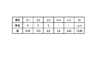
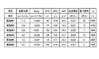
なお、図2は、光ファイバ10の設計パラメータの一例を示す図であり、図3は、図2に示す設計パラメータを用いて数値シミュレーションにより計算した光ファイバ10の光学特性を示す図である。図3において、「MFD」は、モードフィールド径を示し、「β/k」は、伝搬定数βを波数kで除算した実効屈折率を示す。また、図3における理論カットオフ以外の各値は、いずれも波長1550nmにおける値である。なお、β/kが1.4465程度であれば、曲げ損失が10dB/m程度となる。
2 is a diagram illustrating an example of design parameters of the
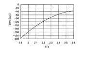
つぎに、光ファイバ10の設計パラメータについて、数値シミュレーションによる計算結果を用いてさらに具体的に説明する。まず、光学特性として、基底伝搬モードであるLP01モードにおける波長分散値を8ps/nm/km以上、β/kを1.4465に維持した場合の、設計パラメータとDPS値または有効コア断面積との関係について調べた。はじめに、中心コア部1、内側コア層2、および外側コア層3がいずれもステップ型の屈折率プロファイルを有しているものとして、Δ2を−0.3%、Δ3を0.2%に固定した場合の、設計パラメータであるΔ1、b/a、c/a、または2aと、分散スロープ値または有効コア断面積との関係について計算した。その結果、図4、5に示すように、b/a、c/aとDPS値との間には相関があり、b/aを2.2以上、c/aを4.15以上にすれば、DPS値を−100nm以上の負の値にできることが確認された。
Next, the design parameters of the
また、図6、7に示すように、Δ1、2aと有効コア断面積との間には相関があり、Δ1を0.52%以下、2aを6.5μm以上にすれば、有効コア断面積を40μm2以上にできることが確認された。 Further, as shown in FIGS. 6 and 7, there is a correlation between Δ1, 2a and the effective core area, and if Δ1 is 0.52% or less and 2a is 6.5 μm or more, the effective core area is Has been confirmed to be 40 μm 2 or more.
同様に、中心コア部1がα型の屈折率プロファイルを有し、内側コア層2、および外側コア層3がいずれもステップ型の屈折率プロファイルを有しているものとして、α1を2からステップ型となる無限大まで変化された場合、Δ2を−0.7%以上、0%未満で変化させた場合、およびΔ3を0.2〜0.4%で変化させた場合についても計算を行った。その結果、Δ1が0.75%以下であり、Δ2が−0.7%以上、0%未満であり、Δ3が0.2〜0.3%であり、b/aが1.5以上であり、c/aが2.8以上であり、2aが6.4μm以上であれば、波長分散値が0ps/nm/kmより大きくなり、β/kが1.4465、DPS値が−100nm以上の負の値、有効コア断面積が40μm2以上となることが確認された。さらに、Δ1が0.6%以下であれば、波長分散値が8ps/nm/km以上となることが確認された。
Similarly, assuming that the
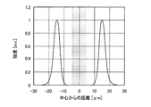
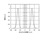
つぎに、本実施の形態1に係る光ファイバ10における伝搬モードについて説明する。図8〜13は、光ファイバ10の波長1550nmにおける伝搬モードのフィールド分布を示す図であり、図8はLP01モード、図9はLP02モード、図10はLP11モード、図11はLP21モード、図12はLP31モード、図13はLP41モードをそれぞれ示す。また、図8〜13において、横軸は中心コア部の中心からの距離を示し、横軸はフィールドの電界強度を任意単位で示す。また、図8〜13中の色付き部分は、ゼロ分散波長が1310nm程度である標準のシングルモード光ファイバのフィールド分布の存在する領域を示している。
Next, a propagation mode in the
図8に示すように、LP01モードは、中心コア部の中心付近をピークとしてフィールドが分布する。また、図9に示すように、LP02モードは、中心コア部の中心付近と、中心コア部の外側の位置とをピークとしてフィールドが分布している。また、図10〜13に示すように、LP11モード〜LP41モードは、中心コア部の外側の位置をピークとしてフィールドが分布している。 As shown in FIG. 8, in the LP01 mode, the field is distributed with a peak near the center of the central core portion. Further, as shown in FIG. 9, in the LP02 mode, fields are distributed with peaks near the center of the central core portion and positions outside the central core portion. As shown in FIGS. 10 to 13, in the LP11 mode to LP41 mode, the field is distributed with the position outside the central core portion as a peak.
ここで、光ファイバ10に標準シングルモード光ファイバを接続し、これを介して光ファイバ10に波長1550nmの信号光を入力する場合を考える。このとき、標準シングルモード光ファイバのフィールド分布は色付きの部分に存在するが、図8に示すように、色付き部分とLP01モードのフィールド分布とは中心付近で重なる。その結果、標準シングルモード光ファイバを介して光ファイバ10に波長1550nmの信号光を入力した場合は、LP01モードが十分に励振されると考えられる。一方、図10〜13においては、色付きの部分とLP11モード〜LP41モードのフィールド分布とはほとんど重ならない。その結果、LP11モード〜LP41はほとんど励振されないと考えられる。他方、図10においては、色付きの部分とLP02モードのフィールド分布とは中心付近で重なるから、LP02モードは励振されるおそれがある。
Here, a case where a standard single mode optical fiber is connected to the
そこで、光ファイバ10に標準シングルモード光ファイバを接続し、これを介して光ファイバ10に波長1550nmの信号光を入力する場合の、信号光の各伝搬モードへの結合効率を、数値シミュレーションを用いて計算した。
Therefore, when a standard single mode optical fiber is connected to the
図14は、伝搬モードと伝搬モードへの信号光の結合効率との関係を示す図である。図14に示すように、LP01モードへの結合効率は、フィールド分布の重なりから予想されるとおりに0.90と大きく、LP11モード〜LP41モードへの結合効率は極めてゼロに近い小さい値であった。一方、LP02モードへの結合効率は0.03であり、LP01モードへの結合効率と比較して十分に小さい値であった。したがって、光ファイバ10に標準シングルモード光ファイバを接続し、これを介して光ファイバ10に信号光を入力することによって、実質的に基底伝搬モードであるLP01モードのみを選択的に励振できることが確認された。
FIG. 14 is a diagram showing the relationship between the propagation mode and the coupling efficiency of signal light into the propagation mode. As shown in FIG. 14, the coupling efficiency to the LP01 mode was as large as 0.90 as expected from the overlap of the field distribution, and the coupling efficiency from the LP11 mode to the LP41 mode was a very small value close to zero. . On the other hand, the coupling efficiency to the LP02 mode was 0.03, which was a sufficiently small value compared to the coupling efficiency to the LP01 mode. Therefore, it is confirmed that only the LP01 mode, which is the fundamental propagation mode, can be selectively excited by connecting a standard single mode optical fiber to the
なお、光ファイバ10に接続するのは、上述のように波長1310nm付近にゼロ分散波長を有する標準のシングルモード光ファイバに限られない。その他のシングルモード光ファイバを接続しても、光ファイバ10のLP01モードのみを選択的に励振できる。
The connection to the
また、上述のように、LP02モードは中心コア部の中心付近と、中心コア部の外側の位置とをピークとしたフィールド分布を有する。したがって、光ファイバ10の設計パラメータを調整して、LP02モードの中心のピーク強度に対する外側のピーク強度の比が大きくなるようすれば、シングルモード光ファイバを介して信号光を入力した場合に励振されるLP02モードの割合が抑制され、LP01モードをさらに高効率で励振できると考えられる。
Further, as described above, the LP02 mode has a field distribution having peaks near the center of the central core portion and at positions outside the central core portion. Therefore, by adjusting the design parameters of the
つぎに、本発明の実施例1〜6として、本実施の形態1に従う光ファイバを実際に作製した場合の光学特性について説明する。図15は、実施例1〜6に係る光ファイバの設計パラメータを示す図であり、図16は、実施例1〜6に係る光ファイバの光学特性を示す図である。なお、図16に示す光学特性は、波長1550nmにおいて測定した基底伝搬モードのものである。また、「λc」はカットオフ波長を示す。カットオフ波長については、信号光波長よりも長波長側に存在するので、従来の光通信用の測定器では測定が困難であるため、設計パラメータからの推測値を示す。 Next, as Examples 1 to 6 of the present invention, optical characteristics when an optical fiber according to the first embodiment is actually manufactured will be described. FIG. 15 is a diagram illustrating design parameters of the optical fibers according to the first to sixth examples, and FIG. 16 is a diagram illustrating optical characteristics of the optical fibers according to the first to sixth examples. Note that the optical characteristics shown in FIG. 16 are of the fundamental propagation mode measured at a wavelength of 1550 nm. “Λc” indicates a cutoff wavelength. Since the cutoff wavelength exists on the longer wavelength side than the signal light wavelength, it is difficult to measure with a conventional measuring instrument for optical communication, so an estimated value from a design parameter is shown.
図16に示すように、実施例1〜6に係る光ファイバは、カットオフ波長が1550nm以上であり、波長1550nmにおける基底伝搬モードの波長分散値が0ps/nm/kmより大きく、分散スロープ値が−0.05ps/nm2/km以下であり、DPS値が−100nm以上の負の値であり、曲げ損失が20dB/m以下であった。 As shown in FIG. 16, the optical fibers according to Examples 1 to 6 have a cutoff wavelength of 1550 nm or more, the chromatic dispersion value of the base propagation mode at the wavelength of 1550 nm is larger than 0 ps / nm / km, and the dispersion slope value is It was −0.05 ps / nm 2 / km or less, the DPS value was a negative value of −100 nm or more, and the bending loss was 20 dB / m or less.
(実施の形態2)
つぎに、本発明の実施の形態2に係る光ファイバ伝送路について説明する。図17は、本実施の形態2に係る光ファイバ伝送路を模式的に表した概略図である。この光ファイバ伝送路100は、nを1以上の整数として、大Aeff型のノンゼロ分散シフト光ファイバ21−1〜21−nと低スロープ型のノンゼロ分散シフト光ファイバ22−1〜22−nとを交互に接続した複合ノンゼロ分散シフト光ファイバ20と、実施の形態1に係る光ファイバ10と、複合ノンゼロ分散シフト光ファイバ20と光ファイバ10との間に介挿された光増幅器30とを備え、複合ノンゼロ分散シフト光ファイバ20側からCバンドのWDM信号光を伝送するものである。
(Embodiment 2)
Next, an optical fiber transmission line according to
ノンゼロ分散シフト光ファイバ21−1〜21−nは、波長1550nmにおいて、−3ps/nm/kmの波長分散値と、0.10ps/nm2/kmの分散スロープ値と、75μm2の有効コア断面積と、0.215dB/kmの伝送損失を有する。一方、光ファイバ22−1〜22−nは、波長1550nmにおいて、−3ps/nm/kmの波長分散値と、0.05ps/nm2/kmの分散スロープ値と、50μm2の有効コア断面積と、0.215dB/kmの伝送損失とを有する。また、ノンゼロ分散シフト光ファイバ21−1〜21−nと22−1〜22−nとはそれぞれ同一の長さを有する。したがって、複合ノンゼロ分散シフト光ファイバ20は、波長1550nmにおいて、全長での平均値として、−3ps/nm/kmの波長分散値と、0.075ps/nm2/kmの分散スロープ値と、63μm2の有効コア断面積と、0.215dB/kmの伝送損失とを有するものとなっている。
The non-zero dispersion shifted optical fibers 21-1 to 21-n have a wavelength dispersion value of −3 ps / nm / km, a dispersion slope value of 0.10 ps / nm 2 / km, and an effective core break of 75 μm 2 at a wavelength of 1550 nm. And has a transmission loss of 0.215 dB / km. On the other hand, the optical fibers 22-1 to 22-n have a wavelength dispersion value of −3 ps / nm / km, a dispersion slope value of 0.05 ps / nm 2 / km, and an effective core area of 50 μm 2 at a wavelength of 1550 nm. And a transmission loss of 0.215 dB / km. The non-zero dispersion shifted optical fibers 21-1 to 21-n and 22-1 to 22-n have the same length. Therefore, the composite non-zero dispersion shifted
光増幅器30は、たとえばエルビウム添加光ファイバ増幅器(EDFA)であり、複合ノンゼロ分散シフト光ファイバ20を伝送したWDM信号光を増幅し、光ファイバ10の伝送損失によるWDM信号光のパワーの減衰を予め補償する。ここで、光増幅器30は、信号光の入出力部に標準のシングルモード光ファイバを備える。その結果、光ファイバ10においては基底伝搬モードのみが選択的に励振され、光ファイバ10はWDM光信号を基底伝搬モードで伝送し、シングルモード光伝送が実現される。
The
また、本実施の形態2に係る光ファイバ伝送路の光入力側に、融着接続などによってシングルモード光ファイバを予め接続しておいてもよい。光ファイバ伝送路の光入力側にシングルモード光ファイバを接続する際に、各中心軸を精密に位置合わせすれば、LP02モードの結合効率比をより低くできるので、光ファイバ伝送路においてより確実に基底伝搬モードを選択的に励振できる。 Further, a single mode optical fiber may be connected in advance to the optical input side of the optical fiber transmission line according to the second embodiment by fusion splicing or the like. When a single mode optical fiber is connected to the optical input side of the optical fiber transmission line, if the center axes are precisely aligned, the coupling efficiency ratio of the LP02 mode can be lowered, so that the optical fiber transmission line can be more reliably connected. The base propagation mode can be selectively excited.
そして、光ファイバ10は、波長1550nmにおける基底伝搬モードの波長分散値が0ps/nm/kmより大きく、分散スロープ値が−0.05ps/nm2/km以下であるから、複合ノンゼロ分散シフト光ファイバ20の波長分散と分散スロープとを同時に補償することができる。その結果、光ファイバ伝送路100は、光信号間の累積波長分散の偏差が大幅に抑制され、より広帯域のWDM伝送に適するものとなる。
Since the
ここで、長さ500kmの光ファイバ伝送路を3本接続し、合計で1500kmの光ファイバ伝送路を構築する場合について、本実施の形態2に係る光ファイバ伝送路100を用いた場合と、光ファイバ伝送路100の光ファイバ10を従来のカットオフシフト光ファイバに置き換えて用いた従来例の場合とで、伝送距離と累積波長分散との関係について比較した。
Here, when three optical fiber transmission lines having a length of 500 km are connected to construct a total optical fiber transmission line of 1500 km, the case where the optical
なお、従来のカットオフシフト光ファイバとして、波長1550nmにおいて、17ps/nm/kmの波長分散値と、0.06ps/nm2/kmの分散スロープ値と、80μm2の有効コア断面積と、0.185dB/kmの伝送損失とを有するものを用い、光ファイバ10として、図3に示した、波長1550nmにおいて9.1ps/nm/kmの波長分散値と、−0.172ps/nm2/kmの分散スロープ値と、79.5μm2の有効コア断面積とを有するものを用いた。
As a conventional cutoff shift optical fiber, at a wavelength of 1550 nm, a chromatic dispersion value of 17 ps / nm / km, a dispersion slope value of 0.06 ps / nm 2 / km, an effective core area of 80 μm 2 , and 0 As the
図18は、従来例の光ファイバ伝送路における伝送距離と累積波長分散との関係を表した分散マップを示す図である。この従来例の光ファイバ伝送路は、波長1550nmの累積波長分散をゼロとするために、425kmの複合ノンゼロ分散シフト光ファイバ20と、75kmのカットオフシフト光ファイバとを交互に接続したものである。その結果、図18に示すように、波長1550nmにおける累積波長分散はゼロであるが、波長1530nmにおける累積波長分散は約−2182.5ps/nmとなり、波長1565nmにおける累積波長分散は約1636.9ps/nmとなる。すなわち、Cバンドの両端での累積波長分散の偏差A1は3819.4ps/nmと極めて大きいものとなる。
FIG. 18 is a diagram showing a dispersion map representing the relationship between transmission distance and cumulative chromatic dispersion in a conventional optical fiber transmission line. In this conventional optical fiber transmission line, a 425 km composite non-zero dispersion shifted
一方、図19は、本実施の形態2に係る光ファイバ伝送路100における伝送距離と累積波長分散との関係を表した分散マップを示す図である。この光ファイバ伝送路100は、波長1550nmの累積波長分散をゼロとするために、376kmの複合ノンゼロ分散シフト光ファイバ20と、124kmの光ファイバ10とを交互に接続したものである。その結果、図19に示すように、波長1550nmにおける累積波長分散はほぼゼロであるとともに、波長1530nmにおける累積波長分散は約−412.8ps/nmとなり、波長1565nmにおける累積波長分散は約309.6ps/nmとなる。すなわち、Cバンドの両端での累積波長分散の偏差は722.4ps/nmであり、従来例よりも大幅に低減されたものとなる。
On the other hand, FIG. 19 is a diagram showing a dispersion map representing the relationship between the transmission distance and the accumulated chromatic dispersion in the optical
また、本実施の形態2において、光ファイバ10の条長は124kmであるから、伝送損失が図16の実施例1と同等の0.237dB/kmとすると、全長での伝送損失は29.4dBである。一方、従来例において、カットオフシフト光ファイバの条長は75kmであるから、全長での伝送損失は13.9dBである。したがって、光ファイバ10の方が全長での伝送損失は大きいが、29.4dB程度であれば、光増幅器30として従来のものを用いて十分に信号光のパワーの減衰を補償できる。
In the second embodiment, since the length of the
上述したように、光ファイバ10は、カットオフシフト光ファイバよりも波長分散値が小さいので、分散補償をするのに必要な条長が長くなり、全長での伝送損失も大きくなる。そこで、光ファイバ10の基底伝搬モードの波長分散値が8ps/nm/km以上であれば、カットオフシフト光ファイバを用いる場合と比較して必要な条長が約2倍以下でよいので好ましい。この場合、光ファイバ10の全長での伝送損失をたとえば30dB程度以下にできるので、従来の光増幅器30を用いて、光ファイバ10における信号光のパワーの減衰を十分に補償できる。
As described above, since the
なお、光ファイバ10の基底伝搬モードの波長分散値が8ps/nm/kmより小さい場合であって、全長での伝送損失がさらに大きくなる場合は、たとえばさらに高利得の光増幅器を用いたり、光ファイバ10を複数に分割し、分割した光ファイバの各々に光増幅器を接続したりすることによって、光ファイバ10における信号光のパワーの減衰を補償できる。
When the chromatic dispersion value of the fundamental propagation mode of the
1 中心コア部
2 内側コア層
3 外側コア層
4 クラッド層
5 屈折率プロファイル
10 光ファイバ
20 複合ノンゼロ分散シフト光ファイバ
21−1〜21−n、22−1〜22−n ノンゼロ分散シフト光ファイバ
30 光増幅器
100 光ファイバ伝送路
DESCRIPTION OF
Claims (6)
中心コア部と、
前記中心コア部の外周に形成され前記中心コア部よりも屈折率が低い内側コア層と、
前記内側コア層の外周に形成され前記中心コア部よりも屈折率が低くかつ前記内側コア層よりも屈折率が高い外側コア層と、
前記外側コア層の周囲に形成され前記内側コア層よりも屈折率が高くかつ前記外側コア層よりも屈折率が低いクラッド層と、
を有し、前記中心コア部の前記クラッド層に対する比屈折率差Δ1が0.3%以上、0.75%以下であり、前記内側コア層の前記クラッド層に対する比屈折率差Δ2が−0.7%以上、0%未満であり、前記外側コア層の前記クラッド層に対する比屈折率差Δ3が0.2%〜0.3%であり、前記中心コア部の直径に対する前記内側コア層の外径の比b/aが1.5以上、2.9以下であり、前記中心コア部の直径に対する前記外側コア層の外径の比c/aが2.8以上、4.8以下であり、前記中心コア部の直径2aが6.4μm以上、12.07μm以下であり、
前記信号光の波長以上のカットオフ波長を有し、
前記信号光の波長における基底伝搬モードの波長分散値が0ps/nm/kmより大きく、15.4ps/nm/km以下であり、分散スロープ値が−0.397ps/nm2/km以上、−0.05ps/nm2/km以下であることを特徴とする光ファイバ。 An optical fiber that transmits signal light having a wavelength of 1550 m in a base propagation mode,
A central core,
An inner core layer formed on the outer periphery of the central core portion and having a lower refractive index than the central core portion;
An outer core layer formed on the outer periphery of the inner core layer and having a refractive index lower than that of the central core portion and higher than that of the inner core layer;
A cladding layer formed around the outer core layer and having a higher refractive index than the inner core layer and a lower refractive index than the outer core layer;
The relative refractive index difference Δ1 of the central core portion with respect to the cladding layer is 0.3% or more and 0.75% or less, and the relative refractive index difference Δ2 of the inner core layer with respect to the cladding layer is −0. 0.7% or more and less than 0%, and the relative refractive index difference Δ3 of the outer core layer to the cladding layer is 0.2% to 0.3%, and the inner core layer has a diameter of the central core portion. The outer diameter ratio b / a is 1.5 or more and 2.9 or less, and the outer diameter ratio c / a of the outer core layer to the diameter of the central core portion is 2.8 or more and 4.8 or less. And the diameter 2a of the central core portion is 6.4 μm or more and 12.07 μm or less,
Having a cutoff wavelength equal to or greater than the wavelength of the signal light;
The chromatic dispersion value of the fundamental propagation mode at the wavelength of the signal light is greater than 0 ps / nm / km and less than or equal to 15.4 ps / nm / km, the dispersion slope value is greater than or equal to −0.397 ps / nm 2 / km, −0 .05 ps / nm 2 / km or less, an optical fiber.
Priority Applications (2)
| Application Number | Priority Date | Filing Date | Title |
|---|---|---|---|
| JP2007062100A JP4851371B2 (en) | 2007-03-12 | 2007-03-12 | Optical fiber and optical fiber transmission line |
| US12/041,230 US7773845B2 (en) | 2007-03-12 | 2008-03-03 | Optical fiber and optical-fiber transmission line |
Applications Claiming Priority (1)
| Application Number | Priority Date | Filing Date | Title |
|---|---|---|---|
| JP2007062100A JP4851371B2 (en) | 2007-03-12 | 2007-03-12 | Optical fiber and optical fiber transmission line |
Publications (2)
| Publication Number | Publication Date |
|---|---|
| JP2008224969A JP2008224969A (en) | 2008-09-25 |
| JP4851371B2 true JP4851371B2 (en) | 2012-01-11 |
Family
ID=39843677
Family Applications (1)
| Application Number | Title | Priority Date | Filing Date |
|---|---|---|---|
| JP2007062100A Expired - Fee Related JP4851371B2 (en) | 2007-03-12 | 2007-03-12 | Optical fiber and optical fiber transmission line |
Country Status (2)
| Country | Link |
|---|---|
| US (1) | US7773845B2 (en) |
| JP (1) | JP4851371B2 (en) |
Families Citing this family (11)
| Publication number | Priority date | Publication date | Assignee | Title |
|---|---|---|---|---|
| JP4851371B2 (en) | 2007-03-12 | 2012-01-11 | 古河電気工業株式会社 | Optical fiber and optical fiber transmission line |
| JP5170909B2 (en) | 2008-02-27 | 2013-03-27 | 古河電気工業株式会社 | Optical transmission system and multi-core optical fiber |
| US8768131B2 (en) * | 2008-08-13 | 2014-07-01 | Corning Incorporated | Multimode fiber with at least dual cladding |
| JP5415728B2 (en) * | 2008-08-29 | 2014-02-12 | 古河電気工業株式会社 | Multi-core holey fiber and optical transmission system |
| CN102257415B (en) * | 2008-12-24 | 2013-10-16 | 古河电气工业株式会社 | Multi-core optical fiber |
| JP5224371B2 (en) * | 2008-12-25 | 2013-07-03 | 古河電気工業株式会社 | Multi-core optical fiber |
| US9075183B2 (en) * | 2009-08-17 | 2015-07-07 | Ofs Fitel, Llc | Optical fibers with truncated cores |
| US8385703B2 (en) * | 2010-03-02 | 2013-02-26 | Corning Incorporated | High numerical aperture multimode optical fiber |
| US8737793B2 (en) | 2010-03-16 | 2014-05-27 | Furukawa Electric Co., Ltd. | Multi-core optical fiber and method of manufacturing the same |
| US9678269B2 (en) | 2014-05-16 | 2017-06-13 | Corning Incorporated | Multimode optical fiber transmission system including single mode fiber |
| US20150331181A1 (en) * | 2014-05-16 | 2015-11-19 | Corning Incorporated | Multimode optical fiber and system including such |
Family Cites Families (8)
| Publication number | Priority date | Publication date | Assignee | Title |
|---|---|---|---|---|
| JPH0923187A (en) * | 1995-07-10 | 1997-01-21 | Fujitsu Ltd | Optical transmission system |
| JPH09318833A (en) * | 1996-03-28 | 1997-12-12 | Furukawa Electric Co Ltd:The | Dispersion shift optical fiber and wavelength multiplexing optical transmission system using the same |
| JP2005196231A (en) * | 1996-04-15 | 2005-07-21 | Sumitomo Electric Ind Ltd | Optical transmission system |
| US6526209B1 (en) * | 2000-04-17 | 2003-02-25 | Sumitomo Electric Industries, Ltd. | Optical fiber having improved optics and structure |
| FR2839221B1 (en) * | 2002-04-29 | 2006-01-27 | Cit Alcatel | FIBER FOR COMPENSATION OF THE CHROMATIC DISPERSION CUMULATED IN A NEGATIVE CHROMATIC DISPERSION FIBER |
| JP4346328B2 (en) | 2003-03-07 | 2009-10-21 | 古河電気工業株式会社 | Optical transmission line |
| JP4481014B2 (en) * | 2004-01-06 | 2010-06-16 | 株式会社フジクラ | Optical fiber transmission line |
| JP4851371B2 (en) | 2007-03-12 | 2012-01-11 | 古河電気工業株式会社 | Optical fiber and optical fiber transmission line |
-
2007
- 2007-03-12 JP JP2007062100A patent/JP4851371B2/en not_active Expired - Fee Related
-
2008
- 2008-03-03 US US12/041,230 patent/US7773845B2/en not_active Expired - Fee Related
Also Published As
| Publication number | Publication date |
|---|---|
| JP2008224969A (en) | 2008-09-25 |
| US20080310807A1 (en) | 2008-12-18 |
| US7773845B2 (en) | 2010-08-10 |
Similar Documents
| Publication | Publication Date | Title |
|---|---|---|
| JP4851371B2 (en) | Optical fiber and optical fiber transmission line | |
| JP5242405B2 (en) | Optical fiber and optical fiber transmission line | |
| JP6397899B2 (en) | Low mode fiber optic optical link for space division multiplexing. | |
| JP5925842B2 (en) | Extended effective area fiber | |
| JP6071030B2 (en) | Large effective area fiber with Ge-free core | |
| JP6397898B2 (en) | Low-mode optical fiber for space division multiplexing. | |
| JP5324012B2 (en) | Multi-core optical fiber and optical transmission system | |
| JP5193398B2 (en) | Optical fiber and optical transmission system | |
| JPWO2008093870A1 (en) | Optical transmission system and dispersion compensating optical fiber | |
| KR20130131291A (en) | Large effective area fiber with graded index ge-free core | |
| US8861915B2 (en) | Optical fiber, optical transmission system, and method for measuring optical fiber | |
| JP4496649B2 (en) | Optical fiber and optical transmission line including the same | |
| JP5059797B2 (en) | Optical fiber, optical fiber design method, and optical wavelength division multiplexing communication system | |
| JP2009517702A (en) | Low attenuation / non-zero dispersion shifted optical fiber | |
| US10782478B2 (en) | Inter-mode loss difference compensator and optical amplifier | |
| JP2009122277A (en) | Optical fiber and optical transmission system | |
| JPWO2010122790A1 (en) | Single mode optical fiber with holes and optical transmission system using the same | |
| US7492999B2 (en) | Optical fiber and optical-fiber transmission line | |
| KR101858459B1 (en) | Dispersion compensating system and dispersion compensating fiber with improved figure of merit | |
| JP2008096933A (en) | Optical communication system and dispersion compensating optical fiber | |
| JP6092029B2 (en) | Multimode optical fiber and optical fiber transmission system | |
| JP5937974B2 (en) | Multimode optical fiber and optical fiber transmission system | |
| JP2008209654A (en) | Optical communication system | |
| JP4570388B2 (en) | Optical transmission line | |
| JP5184011B2 (en) | Optical fiber and optical fiber transmission line |
Legal Events
| Date | Code | Title | Description |
|---|---|---|---|
| A621 | Written request for application examination |
Free format text: JAPANESE INTERMEDIATE CODE: A621 Effective date: 20091102 |
|
| A977 | Report on retrieval |
Free format text: JAPANESE INTERMEDIATE CODE: A971007 Effective date: 20110413 |
|
| A131 | Notification of reasons for refusal |
Free format text: JAPANESE INTERMEDIATE CODE: A131 Effective date: 20110510 |
|
| A521 | Request for written amendment filed |
Free format text: JAPANESE INTERMEDIATE CODE: A523 Effective date: 20110706 |
|
| A131 | Notification of reasons for refusal |
Free format text: JAPANESE INTERMEDIATE CODE: A131 Effective date: 20110802 |
|
| A521 | Request for written amendment filed |
Free format text: JAPANESE INTERMEDIATE CODE: A523 Effective date: 20110927 |
|
| TRDD | Decision of grant or rejection written | ||
| A01 | Written decision to grant a patent or to grant a registration (utility model) |
Free format text: JAPANESE INTERMEDIATE CODE: A01 Effective date: 20111018 |
|
| A01 | Written decision to grant a patent or to grant a registration (utility model) |
Free format text: JAPANESE INTERMEDIATE CODE: A01 |
|
| A61 | First payment of annual fees (during grant procedure) |
Free format text: JAPANESE INTERMEDIATE CODE: A61 Effective date: 20111020 |
|
| FPAY | Renewal fee payment (event date is renewal date of database) |
Free format text: PAYMENT UNTIL: 20141028 Year of fee payment: 3 |
|
| LAPS | Cancellation because of no payment of annual fees |