JP2008196628A - Clutch device - Google Patents
Clutch device Download PDFInfo
- Publication number
- JP2008196628A JP2008196628A JP2007033501A JP2007033501A JP2008196628A JP 2008196628 A JP2008196628 A JP 2008196628A JP 2007033501 A JP2007033501 A JP 2007033501A JP 2007033501 A JP2007033501 A JP 2007033501A JP 2008196628 A JP2008196628 A JP 2008196628A
- Authority
- JP
- Japan
- Prior art keywords
- retaining plate
- plate
- drum
- drive
- snap ring
- Prior art date
- Legal status (The legal status is an assumption and is not a legal conclusion. Google has not performed a legal analysis and makes no representation as to the accuracy of the status listed.)
- Granted
Links
Images


Abstract
Description
本発明は、クラッチ装置に関する。 The present invention relates to a clutch device.
従来、多板式クラッチや多板式ブレーキ等の摩擦係合要素には、動力を入力する側に連設するドライブプレートと、動力を出力する側に連設するドリブンプレートとが交互に配列されており、この両摩擦プレートをリテーニングプレートとピストンとで挟着することで、両摩擦プレートが圧着して両プレート間でトルク授受が行われて動力が伝達される。 Conventionally, in a friction engagement element such as a multi-plate clutch or a multi-plate brake, a drive plate connected to a power input side and a driven plate connected to a power output side are alternately arranged. By sandwiching both the friction plates between the retaining plate and the piston, the friction plates are pressure-bonded, and torque is transmitted and received between the plates to transmit power.
リテーニングプレートをドラムに拘束しておく方法としては、特許文献1と特許文献2が提案されている。特許文献1記載の技術では、リテーニングプレートの一方にスナップリング、他方にリテーニングプレートのクラッチ側への移動を防止するためのスプライン段差またはストッパリングを取り付けた構造となっている。また、特許文献2記載の技術では、リテーニングプレート取付部のドラムにスプライン方向とは直角方向の切欠きを設け、リテーニングプレートの外周突起を当該切欠きに嵌め込み、弾性部材にてリテーニングプレートの抜けを防止する構造となっている。
しかしながら、特許文献1の方法によると、スナップリングおよびリテーニングプレートにプリロードを与えるような寸法に形成されたディッシュプレートをスナップリングとリテーニングプレートとの間に設ける必要があるため、組立作業性が悪化する。さらに、スプラインの途中にストッパとしての段部を形成する必要があり構成が複雑となる。一方、特許文献2の方法によると、リテーニングプレートはトルク伝達方向への回転移動は規制されているものの、スプラインの嵌合溝に平行な方向に対して比較的移動しやすい構成となっている。このため、リテーニングプレートを含めたクラッチ機構が地面に対して斜めに車両に搭載された場合、リテーニングプレートの自重により、リテーニングプレートがドライブプレート側に移動する可能性がある。リテーニングプレートがドライブプレートに押し付けられてしまうと、ピストン非作動時であっても各摩擦プレートが摩擦係合することによりフリクションロスを増大するおそれがある。
However, according to the method of
本発明は、上記問題点に鑑みて成されたものであり、簡単な構成で組立作業性に優れ、リテーニングプレートがドライブプレートに押し付けられる事を防止することができるクラッチ装置を提供することを目的とする。 The present invention has been made in view of the above-described problems, and provides a clutch device that has a simple structure and is excellent in assembling workability and can prevent the retaining plate from being pressed against the drive plate. Objective.
上記課題を解決するために、本発明のクラッチ装置は、ドラム内で軸方向に移動可能なピストンと、前記ドラム内の開口部側に設けられたリテーニングプレートと、前記ピストンと前記リテーニングプレートとの間にドライブハブのスプラインに咬合する複数のドライブプレートと、前記複数のドライブプレートと交互に重ね合わせて嵌装され、前記ドラムのスプラインに咬合する複数のドリブンプレートと、前記ドラムに固定され、前記ドライブプレートと前記ドリブンプレートの脱出を防止するためのスナップリングとを備え、前記リテーニングプレートの前記スナップリングから離間する方向への移動を防止するためのクリップを有する。この構成により、簡単な構成でリテーニングプレートが自重でドライブプレートに押し付けられる事を防止することができる。よって、フリクションロスを低減でき、燃費を向上させることができる。 In order to solve the above problems, a clutch device of the present invention includes a piston that is movable in an axial direction in a drum, a retaining plate provided on an opening side in the drum, the piston, and the retaining plate. A plurality of drive plates that engage with the splines of the drive hub, a plurality of driven plates that are alternately overlapped with the plurality of drive plates, and are engaged with the splines of the drum, and are fixed to the drum And a snap ring for preventing the drive plate and the driven plate from escaping, and a clip for preventing the retaining plate from moving away from the snap ring. With this configuration, it is possible to prevent the retaining plate from being pressed against the drive plate by its own weight with a simple configuration. Therefore, friction loss can be reduced and fuel consumption can be improved.
前記リテーニングプレートは、外周方向の突設された外歯を有し、前記クリップは、前記リテーニングプレートの外歯を把持する把持部と、前記スナップリングに当接して前記リテーニングプレートの軸方向の移動を規制する保持部とを備える。この構成により、簡単な構造でかつ取り付け作業性を向上させることができる。前記保持部は軸方向に弾性変形可能である。この構成により、リテーニングプレートの板厚差を吸収して、厚さの異なるリテーニングプレートに対しても同一のクリップで対応することができる。 The retaining plate has external teeth protruding in the outer peripheral direction, and the clip is in contact with the gripping portion for gripping the external teeth of the retaining plate and the snap ring, and the shaft of the retaining plate And a holding unit that restricts movement in the direction. With this configuration, it is possible to improve the mounting workability with a simple structure. The holding part is elastically deformable in the axial direction. With this configuration, it is possible to absorb the difference in thickness of the retaining plates and cope with retaining plates having different thicknesses with the same clip.
本発明によれば、簡単な構成でリテーニングプレートがドライブプレートに押し付けられる事を防止することができるクラッチ装置を提供できる。 According to the present invention, it is possible to provide a clutch device that can prevent the retaining plate from being pressed against the drive plate with a simple configuration.
以下、本発明の最良の実施形態について、添付図面を参照しつつ説明する。 DESCRIPTION OF EXEMPLARY EMBODIMENTS Hereinafter, exemplary embodiments of the invention will be described with reference to the accompanying drawings.
図1は、本発明の実施形態に係るクラッチ装置1を説明するための図である。図示は省略するが、自動変速機の動力伝達列には、入力側からトルクコンバータ、オイルポンプ、多段変速機3が配設され、エンジン出力軸からの駆動力がトルクコンバータを経て多段変速機3の入力軸に伝達される。
FIG. 1 is a view for explaining a
多段変速機3は、フロントプラネタリギヤユニット3aとリヤプラネタリギヤユニット3bとを備えている。フロントプラネタリギヤユニット3aの側方に、ハイクラッチ(不図示)、リバースクラッチ9、ブレーキ10が並列に配設されている。リバースクラッチ9のリバースクラッチドラム9aがハイクラッチドラム(不図示)に連続して形成されており、このリバースクラッチドラム9aに対設するリバースクラッチハブ9bがフロントプラネタリギヤユニット3aのフロントリングギヤに連設されている。リバースクラッチハブ9bがブレーキ10のブレーキハブ10aに連設され、このブレーキハブ10aに対設する円筒形のブレーキドラム10bが自動変速機ケースに一体形成されている。
The
両プラネタリギヤユニット3a,3bの外周に、ロークラッチ13が配設され、このロークラッチ13のロークラッチドラム13aがフロントプラネタリキャリヤに連設され、このロークラッチドラム13aに対設するロークラッチハブがリヤプラネタリギヤユニット3bのリヤリングギヤに連設されている。
A
ブレーキ10は、ブレーキドラム10bのトルクコンバータ方向に指向する開口端の内周にスナップリング16が嵌着され、このスナップリング16の内方にリテーニングプレート17が配設され、このリテーニングプレート17の内方面にドライブプレート18aとドリブンプレート18bとが交互に配設され、最内部のドライブプレート18aの内方面にプレッシャプレート19が配設され、このプレッシャプレート19の内方面に、図示しないピストン作動室から延出するブレーキピストン20が対設されている。
In the
リテーニングプレート17は、ドラム内の開口部側に設けられ、外周方向に突設するように設けられた外歯17aを有する。ブレーキピストン20は、ドラム内の底面側に軸方向に移動可能である。ドライブプレート18aとドリブンプレート18bは、摩擦締結部材として機能するものである。複数のドライブプレート18aは、ブレーキピストン20とリテーニングプレート17との間にブレーキハブ10aのスプライン10cに咬合され、軸方向に移動可能に支持されている。
The
複数のドリブンプレート18bは、複数のドライブプレート18aと交互に重ね合わせて嵌装され、ブレーキドラム10bのスプライン10dに咬合され、軸方向に移動可能に支持されている。プレッシャプレート19は、ドライブプレート18aおよびドリブンプレート18bを軸方向に押圧するものである。リテーニングプレート17、ドライブプレート18aおよびドリブンプレート18bとで摩擦プレートを形成している。スナップリング16は、ブレーキドラム10bに固定され、ドライブプレート18aとドリブンプレート18bの脱出を防止するためのものである。クリップ30は、板状の弾性部材であり、リテーニングプレート17をスナップリング16に固定するために用いられ、リテーニングプレート17のスナップリング16から離間する方向への移動を防止する。このクリップ30は、リテーニングプレート17の溝部の空間を利用して、スナップリング16にリテーニングプレート17を係止する。
The plurality of driven
以上のようなクラッチ装置1では、ブレーキピストン20はその背面側に供給される油圧によってリターンスプリングに抗して摩擦プレートを押圧する方向に移動するようになされている。また、リテーニングプレート17、ドリブンプレート18bはブレーキドラム10bと共回りし、ドライブプレート18aはブレーキハブ10aと共回りしてこれらは各々異速回転しており、ブレーキピストン20に油圧が作動してドライブプレート18a、ドリブンプレート18bが押圧されると、これらは互いに摩擦しながら次第に締結されブレーキドラム10bとブレーキハブ10aとが同速回転になりブレーキハブ10aの回転力が伝達される。そして、ブレーキドラム10bとブレーキハブ10aとが異速回転中には軸芯から油路を経由して油が供給されて、遠心力によりブレーキハブ10aに形成された穴から摩擦プレートに供給され摩擦プレートの潤滑と冷却が行われる。
In the
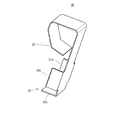
図2は、クリップ30の拡大斜視図である。図3は、図2で示したクリップの使用状態を示す図である。クリップ30は、リテーニングプレート17の外歯17aを把持する把持部31と、スナップリング16に当接する際に軸方向に弾性変形可能な保持部32とを備える。把持部31は3枚の把持板31a、31b、31cによって構成され、リテーニングプレート17の外歯17と取り囲むように外歯17の周方向側面とクラッチ板側の下部を把持する。なお、リテーニングプレートはクラッチクリアランスを調整するために数種類の厚さの異なるもの中から選択して使用される。上記の様にクリップ30の保持部32は軸方向に弾性変形可能なため、リテーニングプレートの板厚差を吸収して、厚さの異なるリテーニングプレートに対しても同一のクリップで対応することができる。
FIG. 2 is an enlarged perspective view of the
クリップ30の使用に際しては、まず、リテーニングプレート17の外歯17aにクリップ30の把持部31を取り付ける。リテーニングプレート17を自動変速機ケース内に挿入する。次に、クリップ30の保持部32とリテーニングプレート17の間にスナップリング16を固定する。本実施形態に係るクラッチ装置1では、リテーニングプレート17の抜け止めに用いているスナップリング16とリテーニングプレート17を弾性部材であるクリップ30で係合しておくことにより、多板クラッチの回転軸が傾いた場合においても、スナップリング16がリテーニングプレート17を係止しているため、保持部32がリテーニングプレートの軸方向の移動を規制して、リテーニングプレート17の重力による軸方向力がクラッチ板に作用しなくなる。
When using the
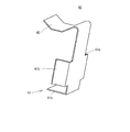
図4は、クリップの形状の変形例を示す図である。図5は、図4で示したクリップの使用状態を示す図である。クリップ40は、リテーニングプレート17の外歯17aを把持する把持部41と、スナップリング16に接触する際に弾性変形可能な保持部42とを備える。この保持部42の形状が図2のクリップ30とは異なる。
FIG. 4 is a diagram showing a modification of the shape of the clip. FIG. 5 is a diagram illustrating a usage state of the clip illustrated in FIG. 4. The
クリップ40の使用に際しては、まず、リテーニングプレート17の外歯17aにクリップ40の把持部41を取り付ける。リテーニングプレート17を自動変速機ケース内に挿入する。次に、クリップ40の保持部42とリテーニングプレート17の間にスナップリング16を固定する。把持板41a、41b、41cによって左右と下部を把持する。
When using the
以上、本発明の実施形態に係るクラッチ装置では、リテーニングプレート17をスナップリング16に固定するためのクリップ30、40を設けることにより、多板クラッチの回転軸の傾きによりリテーニングプレート17がクラッチ板の方へ移動して、クラッチ板がリテーニングプレート17により一方向に押し付けられ、クラッチ板が摺動回転するのを防止することができる。よって、フリクションロスを低減でき、燃費を向上させることができる。
As described above, in the clutch device according to the embodiment of the present invention, by providing the
以上、本発明の好ましい実施例について詳述したが、本発明は上述した実施例に限定されるものではなく、特許請求の範囲に記載された本発明の要旨の範囲内において、種々の変形、変更が可能である。 The preferred embodiments of the present invention have been described in detail above. However, the present invention is not limited to the above-described embodiments, and various modifications may be made within the scope of the gist of the present invention described in the claims. It can be changed.
1…クラッチ装置
3…多段変速機
3a…フロントプラネタリギヤユニット
3b…リヤプラネタリギヤユニット
9…クラッチ
9a…リバースクラッチドラム
9b…リバースクラッチハブ
10…ブレーキ
10a…ブレーキハブ
10b…ブレーキドラム
13…ロークラッチ
13a…ロークラッチドラム
16…スナップリング
17…リテーニングプレート
17a…外歯
18a…ドライブプレート
18b…ドリブンプレート
19…プレッシャプレート
20…ブレーキピストン
30、40…クリップ
31、41…保持部
32、42…接触部
DESCRIPTION OF
Claims (3)
前記ドラム内の開口部側に設けられたリテーニングプレートと、
前記ピストンと前記リテーニングプレートとの間にドライブハブのスプラインに咬合する複数のドライブプレートと、
前記複数のドライブプレートと交互に重ね合わせて嵌装され、前記ドラムのスプラインに咬合する複数のドリブンプレートと、
前記ドラムに固定され、前記ドライブプレートと前記ドリブンプレートの脱出を防止するためのスナップリングとを備え、
前記リテーニングプレートの前記スナップリングから離間する方向への移動を防止するためのクリップを有することを特徴とするクラッチ装置。 A piston movable axially within the drum;
A retaining plate provided on the opening side in the drum;
A plurality of drive plates that engage a spline of a drive hub between the piston and the retaining plate;
A plurality of driven plates that are alternately overlapped and fitted with the plurality of drive plates and mesh with the splines of the drum;
A snap ring fixed to the drum, for preventing the drive plate and the driven plate from escaping;
A clutch device comprising a clip for preventing the retaining plate from moving in a direction away from the snap ring.
前記クリップは、前記リテーニングプレートの外歯を把持する把持部と、前記スナップリングに当接して前記リテーニングプレートの軸方向の移動を規制する保持部と、を備えることを特徴とする請求項1に記載のクラッチ装置。 The retaining plate has external teeth protruding in the outer peripheral direction,
The clip includes a holding portion that holds external teeth of the retaining plate, and a holding portion that contacts the snap ring and restricts movement of the retaining plate in the axial direction. The clutch device according to 1.
Priority Applications (1)
| Application Number | Priority Date | Filing Date | Title |
|---|---|---|---|
| JP2007033501A JP4818150B2 (en) | 2007-02-14 | 2007-02-14 | Clutch device |
Applications Claiming Priority (1)
| Application Number | Priority Date | Filing Date | Title |
|---|---|---|---|
| JP2007033501A JP4818150B2 (en) | 2007-02-14 | 2007-02-14 | Clutch device |
Publications (2)
| Publication Number | Publication Date |
|---|---|
| JP2008196628A true JP2008196628A (en) | 2008-08-28 |
| JP4818150B2 JP4818150B2 (en) | 2011-11-16 |
Family
ID=39755760
Family Applications (1)
| Application Number | Title | Priority Date | Filing Date |
|---|---|---|---|
| JP2007033501A Expired - Fee Related JP4818150B2 (en) | 2007-02-14 | 2007-02-14 | Clutch device |
Country Status (1)
| Country | Link |
|---|---|
| JP (1) | JP4818150B2 (en) |
Cited By (1)
| Publication number | Priority date | Publication date | Assignee | Title |
|---|---|---|---|---|
| CN109268402A (en) * | 2018-09-30 | 2019-01-25 | 厦门南超机械有限公司 | A kind of clutch and its installation method with follower |
Families Citing this family (1)
| Publication number | Priority date | Publication date | Assignee | Title |
|---|---|---|---|---|
| US10371215B2 (en) | 2016-06-28 | 2019-08-06 | Ford Global Technologies, Llc | Transmission and transmission clutch system |
Citations (5)
| Publication number | Priority date | Publication date | Assignee | Title |
|---|---|---|---|---|
| JPS61133149A (en) * | 1984-11-30 | 1986-06-20 | 花王株式会社 | Manufacture of ultrafine particle |
| JPH04107324A (en) * | 1990-08-24 | 1992-04-08 | Nissan Motor Co Ltd | Wet type multiple disk clutch |
| JPH0587156A (en) * | 1991-06-17 | 1993-04-06 | Jatco Corp | Friction fastening device |
| JPH0953657A (en) * | 1995-08-10 | 1997-02-25 | Yamakawa Ind Co Ltd | Multiple disk clutch structure |
| JP2002250367A (en) * | 2001-02-22 | 2002-09-06 | Exedy Corp | Multiple disc clutch device |
-
2007
- 2007-02-14 JP JP2007033501A patent/JP4818150B2/en not_active Expired - Fee Related
Patent Citations (5)
| Publication number | Priority date | Publication date | Assignee | Title |
|---|---|---|---|---|
| JPS61133149A (en) * | 1984-11-30 | 1986-06-20 | 花王株式会社 | Manufacture of ultrafine particle |
| JPH04107324A (en) * | 1990-08-24 | 1992-04-08 | Nissan Motor Co Ltd | Wet type multiple disk clutch |
| JPH0587156A (en) * | 1991-06-17 | 1993-04-06 | Jatco Corp | Friction fastening device |
| JPH0953657A (en) * | 1995-08-10 | 1997-02-25 | Yamakawa Ind Co Ltd | Multiple disk clutch structure |
| JP2002250367A (en) * | 2001-02-22 | 2002-09-06 | Exedy Corp | Multiple disc clutch device |
Cited By (2)
| Publication number | Priority date | Publication date | Assignee | Title |
|---|---|---|---|---|
| CN109268402A (en) * | 2018-09-30 | 2019-01-25 | 厦门南超机械有限公司 | A kind of clutch and its installation method with follower |
| CN109268402B (en) * | 2018-09-30 | 2024-03-26 | 厦门南超机械有限公司 | Clutch and method for mounting clutch and driven mechanism |
Also Published As
| Publication number | Publication date |
|---|---|
| JP4818150B2 (en) | 2011-11-16 |
Similar Documents
| Publication | Publication Date | Title |
|---|---|---|
| JP5025249B2 (en) | Starting clutch | |
| US7966901B2 (en) | Torque transfer device | |
| EP3361112B1 (en) | Clutch apparatus | |
| US10138949B2 (en) | Friction engagement element | |
| KR101328541B1 (en) | Roller, sprag or ratchet one-way clutch with two backing plates | |
| JP2007315558A (en) | Mechanical joint type multiplate wet clutch | |
| JP2008309317A (en) | Starter | |
| JP3944218B2 (en) | Motorcycle clutch device | |
| JP3631974B2 (en) | clutch | |
| JP4818150B2 (en) | Clutch device | |
| JP4662899B2 (en) | Multi-plate clutch | |
| JP4831575B2 (en) | Starting clutch | |
| JP2009103281A (en) | Power transmission device | |
| JP4370350B2 (en) | Motorcycle clutch device | |
| JP2005098409A (en) | Clutch device | |
| JP5044208B2 (en) | Starting clutch | |
| JP4942469B2 (en) | Starting clutch | |
| KR101600977B1 (en) | Clutch for automatic transmission | |
| JP7252405B1 (en) | Clutch device and motorcycle | |
| JP5295157B2 (en) | Lock-up clutch device | |
| JP2012177435A (en) | Friction engaging device | |
| CN107387590B (en) | Clutch device capable of maintaining state | |
| JP2009052603A (en) | Starting clutch apparatus | |
| JP5005577B2 (en) | Clutch device | |
| JP2014119009A (en) | Friction fastening device of automatic transmission and change method for torque capacity thereof |
Legal Events
| Date | Code | Title | Description |
|---|---|---|---|
| A621 | Written request for application examination |
Free format text: JAPANESE INTERMEDIATE CODE: A621 Effective date: 20091222 |
|
| A521 | Written amendment |
Free format text: JAPANESE INTERMEDIATE CODE: A523 Effective date: 20100126 |
|
| A521 | Written amendment |
Free format text: JAPANESE INTERMEDIATE CODE: A523 Effective date: 20100126 |
|
| A131 | Notification of reasons for refusal |
Free format text: JAPANESE INTERMEDIATE CODE: A131 Effective date: 20110621 |
|
| A977 | Report on retrieval |
Free format text: JAPANESE INTERMEDIATE CODE: A971007 Effective date: 20110623 |
|
| A521 | Written amendment |
Free format text: JAPANESE INTERMEDIATE CODE: A523 Effective date: 20110809 |
|
| TRDD | Decision of grant or rejection written | ||
| A01 | Written decision to grant a patent or to grant a registration (utility model) |
Free format text: JAPANESE INTERMEDIATE CODE: A01 Effective date: 20110826 |
|
| A01 | Written decision to grant a patent or to grant a registration (utility model) |
Free format text: JAPANESE INTERMEDIATE CODE: A01 |
|
| A61 | First payment of annual fees (during grant procedure) |
Free format text: JAPANESE INTERMEDIATE CODE: A61 Effective date: 20110830 |
|
| FPAY | Renewal fee payment (event date is renewal date of database) |
Free format text: PAYMENT UNTIL: 20140909 Year of fee payment: 3 |
|
| R150 | Certificate of patent or registration of utility model |
Free format text: JAPANESE INTERMEDIATE CODE: R150 |
|
| R250 | Receipt of annual fees |
Free format text: JAPANESE INTERMEDIATE CODE: R250 |
|
| S531 | Written request for registration of change of domicile |
Free format text: JAPANESE INTERMEDIATE CODE: R313531 |
|
| R350 | Written notification of registration of transfer |
Free format text: JAPANESE INTERMEDIATE CODE: R350 |
|
| R250 | Receipt of annual fees |
Free format text: JAPANESE INTERMEDIATE CODE: R250 |
|
| R250 | Receipt of annual fees |
Free format text: JAPANESE INTERMEDIATE CODE: R250 |
|
| LAPS | Cancellation because of no payment of annual fees |