JP2008152012A - Imaging element, focus detection device and imaging apparatus - Google Patents
Imaging element, focus detection device and imaging apparatus Download PDFInfo
- Publication number
- JP2008152012A JP2008152012A JP2006339856A JP2006339856A JP2008152012A JP 2008152012 A JP2008152012 A JP 2008152012A JP 2006339856 A JP2006339856 A JP 2006339856A JP 2006339856 A JP2006339856 A JP 2006339856A JP 2008152012 A JP2008152012 A JP 2008152012A
- Authority
- JP
- Japan
- Prior art keywords
- focus detection
- pixels
- pixel
- area
- detection pixels
- Prior art date
- Legal status (The legal status is an assumption and is not a legal conclusion. Google has not performed a legal analysis and makes no representation as to the accuracy of the status listed.)
- Granted
Links
Images


Classifications
-
- H—ELECTRICITY
- H04—ELECTRIC COMMUNICATION TECHNIQUE
- H04N—PICTORIAL COMMUNICATION, e.g. TELEVISION
- H04N23/00—Cameras or camera modules comprising electronic image sensors; Control thereof
- H04N23/60—Control of cameras or camera modules
- H04N23/67—Focus control based on electronic image sensor signals
- H04N23/672—Focus control based on electronic image sensor signals based on the phase difference signals
-
- H—ELECTRICITY
- H04—ELECTRIC COMMUNICATION TECHNIQUE
- H04N—PICTORIAL COMMUNICATION, e.g. TELEVISION
- H04N23/00—Cameras or camera modules comprising electronic image sensors; Control thereof
- H04N23/60—Control of cameras or camera modules
- H04N23/67—Focus control based on electronic image sensor signals
- H04N23/675—Focus control based on electronic image sensor signals comprising setting of focusing regions
-
- H—ELECTRICITY
- H04—ELECTRIC COMMUNICATION TECHNIQUE
- H04N—PICTORIAL COMMUNICATION, e.g. TELEVISION
- H04N23/00—Cameras or camera modules comprising electronic image sensors; Control thereof
- H04N23/80—Camera processing pipelines; Components thereof
- H04N23/84—Camera processing pipelines; Components thereof for processing colour signals
- H04N23/843—Demosaicing, e.g. interpolating colour pixel values
-
- H—ELECTRICITY
- H04—ELECTRIC COMMUNICATION TECHNIQUE
- H04N—PICTORIAL COMMUNICATION, e.g. TELEVISION
- H04N25/00—Circuitry of solid-state image sensors [SSIS]; Control thereof
- H04N25/10—Circuitry of solid-state image sensors [SSIS]; Control thereof for transforming different wavelengths into image signals
- H04N25/11—Arrangement of colour filter arrays [CFA]; Filter mosaics
- H04N25/13—Arrangement of colour filter arrays [CFA]; Filter mosaics characterised by the spectral characteristics of the filter elements
- H04N25/134—Arrangement of colour filter arrays [CFA]; Filter mosaics characterised by the spectral characteristics of the filter elements based on three different wavelength filter elements
-
- H—ELECTRICITY
- H04—ELECTRIC COMMUNICATION TECHNIQUE
- H04N—PICTORIAL COMMUNICATION, e.g. TELEVISION
- H04N25/00—Circuitry of solid-state image sensors [SSIS]; Control thereof
- H04N25/70—SSIS architectures; Circuits associated therewith
- H04N25/702—SSIS architectures characterised by non-identical, non-equidistant or non-planar pixel layout
-
- H—ELECTRICITY
- H04—ELECTRIC COMMUNICATION TECHNIQUE
- H04N—PICTORIAL COMMUNICATION, e.g. TELEVISION
- H04N25/00—Circuitry of solid-state image sensors [SSIS]; Control thereof
- H04N25/70—SSIS architectures; Circuits associated therewith
- H04N25/703—SSIS architectures incorporating pixels for producing signals other than image signals
- H04N25/704—Pixels specially adapted for focusing, e.g. phase difference pixel sets
Abstract
Description
本発明は撮像素子、焦点検出装置および撮像装置に関する。 The present invention relates to an imaging element, a focus detection device, and an imaging device.
瞳分割型位相差検出方式を用いた焦点検出用画素を撮像素子中央の水平方向に配置し、その周辺に撮像用画素を配置した撮像素子が知られている(例えば、特許文献1参照)。 There is known an image pickup device in which focus detection pixels using a pupil division type phase difference detection method are arranged in the horizontal direction at the center of the image pickup device, and image pickup pixels are arranged around the focus detection pixel (for example, see Patent Document 1).
この出願の発明に関連する先行技術文献としては次のものがある。
上述した従来の撮像素子では、焦点検出用画素を撮像素子中央の水平方向にのみ配列しているので、焦点検出対象の被写体を画面中央で捕捉しなければならず、焦点検出機能に制約がある。この問題を解決するために、焦点検出用画素を画面全域に展開すると、焦点検出用画素位置の画像出力を周囲の撮像用画素の出力に基づいて補間するときに画像品質が劣化する。したがって、撮像機能の観点からの要求と、焦点検出機能の観点からの要求との両立を図り、画像品質を維持しながら焦点検出性能を向上させる必要がある。 In the conventional image sensor described above, the focus detection pixels are arranged only in the horizontal direction at the center of the image sensor, so the subject to be detected by the focus detection must be captured at the center of the screen, and the focus detection function is limited. . In order to solve this problem, if the focus detection pixels are developed over the entire screen, the image quality deteriorates when the image output at the focus detection pixel position is interpolated based on the outputs of the surrounding imaging pixels. Therefore, it is necessary to improve the focus detection performance while maintaining the image quality by satisfying both the requirement from the viewpoint of the imaging function and the requirement from the viewpoint of the focus detection function.
(1) 請求項1の発明は、二次元状に配列された撮像用画素の配列中に、瞳分割式の第1焦点検出用画素とこの第1焦点検出用画素とは異なる瞳分割式の第2焦点検出用画素とを配列し、光学系によって結像された像を電気信号に変換する撮像素子であって、第1焦点検出用画素と第2焦点検出用画素が配置される位置の、撮像素子の中心からの方向に応じて、配置される第1焦点検出用画素と第2焦点検出用画素の数の大小関係を決定する。
(2) 請求項2の撮像素子は、撮像素子を、第1焦点検出用画素が配列される第1方向に沿った第1区域と、第2焦点検出用画素が配列される第2方向に沿った第2区域とに区分した場合、第1区域には第2焦点検出用画素を第1焦点検出用画素よりも多く配置するとともに、第2区域には第1焦点検出用画素を第2焦点検出用画素よりも多く配置するようにしたものである。
(3) 請求項3の撮像素子は、前記大小関係を撮像素子の中心からの距離に応じて決めるようにしたものである。
(4) 請求項4の発明は、二次元状に配列された撮像用画素の配列中の画素配列が稠密な第1方向と第2方向のそれぞれに沿って第1焦点検出用画素と第2焦点検出用画素を配列し、光学系によって結像された像を電気信号に変換する撮像素子であって、撮像素子を、光学系の光軸が通る位置を基準として第1および第2方向とは異なる放射方向に延びる境界線によって、第1方向に沿った第1区域と第2方向に沿った第2区域とに区分した場合に、第1区域には第2焦点検出用画素が第1焦点検出用画素よりも多数存在するように配置するとともに、第2区域には第1焦点検出用画素が第2焦点検出用画素よりも多数存在するように配置するようにしたものである。
(5) 請求項5の撮像素子は、境界線を第1および第2方向に対して45度に傾斜したものである。
(6) 請求項6の撮像素子は、第1焦点検出画素の光電変換部の大きさと第2焦点検出画素の光電変換部の大きさとが異なるようにしたものである。
(7) 請求項7の撮像素子は、第1区域に配置された第1焦点検出画素の光電変換部の大きさは、第1区域に配置された第2焦点検出画素の光電変換部の大きさよりも小さくしたものである。
(8) 請求項8の撮像素子は、第1焦点検出画素と第2焦点検出画素が、それぞれ一つの光電変換部を有するとともに、互いに隣接する第1焦点検出画素どうしの光電変換部、または互いに隣接する第2焦点検出画素どうしの光電変換部を組とするようにしたものである。
(9) 請求項9の発明は、二次元状に配列された撮像用画素の配列中に第1焦点検出用画素と第2焦点検出用画素を配列し、光学系によって結像された像を電気信号に変換する撮像素子であって、第1焦点検出用画素は、光学系の射出瞳上の第1方向に並ぶ一対の領域の少なくとも一方を通過した光束を受光する光電変換部を有するとともに、複数の第1焦点検出用画素を第1方向に対応する方向に配列して第1の焦点検出領域を形成し、第2焦点検出用画素は、光学系の射出瞳上の第1方向と異なる第2方向に並ぶ一対の領域の少なくとも一方を通過した光束を受光する光電変換部を有するとともに、複数の第2焦点検出用画素を第2方向に対応する方向に配列して第2の焦点検出領域を形成し、撮像素子を、光学系の光軸が通る位置を基準として第1および第2方向とは異なる放射方向に延びる境界線によって、第1方向に対応する方向に沿った第1区域と第2方向に対応する方向に沿った第2区域とに区分した場合に、第1区域には第2焦点検出用画素が第1焦点検出用画素よりも多数存在するように配置するとともに、第2区域には第1焦点検出用画素が第2焦点検出用画素よりも多数存在するように配置したものである。
(10) 請求項10の撮像素子は、第1区域では、第2焦点検出用画素の数に対する第1焦点検出用画素の数の割合を前記光軸が通る位置から離れるにしたがって小さくするとともに、第2区域では、第1焦点検出用画素の数に対する第2焦点検出用画素の数の割合を光軸が通る位置から離れるにしたがって小さくしたものである。
(11) 請求項11の撮像素子は、撮像素子の画素配列の中央部には、第1の焦点検出領域と第2の焦点検出領域とを交差して配置するようにしたものである。
(12) 請求項12の撮像素子は、撮像素子の画素配列の周辺部における第1区域には第2焦点検出用画素のみを配置するとともに、撮像素子の画素配列の周辺部における第2区域には第1焦点検出用画素のみを配置したものである。
(13) 請求項13の撮像素子は、第1方向と第2方向を、撮像素子の画素配列のうち画素が稠密となる方向としたものである。
(14) 請求項14の発明は、請求項1〜13のいずれか1項に記載の撮像素子と、第1焦点検出用画素と第2焦点検出用画素の出力に基づいて光学系の焦点調節状態を検出する焦点検出手段とを備えた焦点検出装置である。
(15) 請求項12の発明は、請求項1〜13のいずれか1項に記載の撮像素子と、第1焦点検出用画素と第2焦点検出用画素の位置における画像出力を、周囲の撮像用画素の出力に基づいて補間する補間手段と、補間手段により補間された第1焦点検出用画素と第2焦点検出用画素の位置における画像出力と、撮像用画素の出力とに基づいて画像信号を生成する制御手段とを備えた撮像装置である。
(1) According to the first aspect of the present invention, the pupil division type first focus detection pixel and the first focus detection pixel are different from each other in the two-dimensional arrangement of the imaging pixels. An image sensor that arranges the second focus detection pixels and converts an image formed by the optical system into an electrical signal, at a position where the first focus detection pixels and the second focus detection pixels are arranged. The magnitude relationship between the number of first focus detection pixels and second focus detection pixels to be arranged is determined according to the direction from the center of the image sensor.
(2) In the image pickup device according to
(3) In the image pickup device according to the third aspect, the magnitude relationship is determined according to the distance from the center of the image pickup device.
(4) According to the invention of
(5) The image pickup device according to
(6) The image pickup device according to claim 6 is configured such that the size of the photoelectric conversion unit of the first focus detection pixel is different from the size of the photoelectric conversion unit of the second focus detection pixel.
(7) In the imaging device according to the seventh aspect, the size of the photoelectric conversion unit of the first focus detection pixel arranged in the first area is equal to the size of the photoelectric conversion unit of the second focus detection pixel arranged in the first area. It is smaller than this.
(8) In the imaging device according to the eighth aspect, the first focus detection pixel and the second focus detection pixel each have one photoelectric conversion unit, and the photoelectric conversion units between the first focus detection pixels adjacent to each other, or each other. A photoelectric conversion unit between adjacent second focus detection pixels is used as a set.
(9) According to the invention of claim 9, the first focus detection pixel and the second focus detection pixel are arranged in an array of imaging pixels arranged two-dimensionally, and an image formed by the optical system is obtained. The first focus detection pixel, which is an image sensor that converts an electrical signal, includes a photoelectric conversion unit that receives a light beam that has passed through at least one of a pair of regions arranged in the first direction on the exit pupil of the optical system. A plurality of first focus detection pixels are arranged in a direction corresponding to the first direction to form a first focus detection region, and the second focus detection pixels are arranged in the first direction on the exit pupil of the optical system. A photoelectric conversion unit that receives a light beam that has passed through at least one of a pair of regions arranged in different second directions, and a second focus by arranging a plurality of second focus detection pixels in a direction corresponding to the second direction A detection area is formed and the image sensor is positioned based on the position through which the optical axis of the optical system passes. By a boundary line extending in a radial direction different from the first and second directions as a quasi, it is divided into a first area along a direction corresponding to the first direction and a second area along a direction corresponding to the second direction. In this case, the first focus detection pixels are arranged in the first area so that there are more second focus detection pixels than the first focus detection pixels, and the first focus detection pixels are in the second area. It arrange | positions so that many may exist.
(10) In the imaging device according to
(11) In the image pickup device according to the eleventh aspect, the first focus detection region and the second focus detection region are arranged so as to cross each other at the center of the pixel array of the image pickup device.
(12) In the image pickup device according to
(13) In the imaging device according to a thirteenth aspect, the first direction and the second direction are directions in which pixels are dense in the pixel array of the imaging device.
(14) According to the fourteenth aspect of the present invention, the focus adjustment of the optical system is performed based on the output of the imaging element according to any one of the first to thirteenth aspects and the first focus detection pixel and the second focus detection pixel. It is a focus detection apparatus provided with the focus detection means which detects a state.
(15) According to the invention of
本発明によれば、撮像機能の観点からの要求と焦点検出機能の観点からの要求とを両立させ、画像品質を維持しながら焦点検出性能を向上させることができる。 According to the present invention, it is possible to satisfy both a request from the viewpoint of the imaging function and a request from the viewpoint of the focus detection function, and improve the focus detection performance while maintaining the image quality.
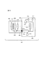
本願発明の一実施の形態による撮像素子、焦点検出装置および撮像装置をデジタルスチルカメラに適用した例を説明する。図1は一実施の形態の構成を示す。一実施の形態のデジタルスチルカメラ201は交換レンズ202とカメラボディ203から構成され、交換レンズ202はマウント部204によりカメラボディ203に装着される。
An example in which an image sensor, a focus detection device, and an image pickup device according to an embodiment of the present invention are applied to a digital still camera will be described. FIG. 1 shows the configuration of an embodiment. A
交換レンズ202はレンズ駆動制御装置206、ズーミング用レンズ208、レンズ209、フォーカシング用レンズ210、絞り211などを備えている。レンズ駆動制御装置206は、マイクロコンピューターとメモリなどの周辺部品から成り、フォーカシング用レンズ210と絞り211の駆動制御、絞り211、ズーミング用レンズ208およびフォーカシング用レンズ210の状態検出、後述するボディ駆動制御装置214に対するレンズ情報の送信とカメラ情報の受信などを行う。
The
カメラボディ203は撮像素子212、ボディ駆動制御装置214、液晶表示素子駆動回路215、液晶表示素子216、接眼レンズ217、メモリカード219などを備えている。撮像素子212には後述する画素が二次元状に配列されており、交換レンズ202の予定結像面に配置されて交換レンズ202により結像される被写体像を撮像する。なお、詳細を後述するが撮像素子212の所定の焦点検出位置には焦点検出用画素が配列される。
The
ボディ駆動制御装置214はマイクロコンピューターとメモリなどの周辺部品から構成され、撮像素子212からの画像信号の読み出し、画像信号の補正、交換レンズ202の焦点調節状態の検出、レンズ駆動制御装置206からのレンズ情報の受信とカメラ情報(デフォーカス量)の送信、ディジタルスチルカメラ全体の動作制御などを行う。ボディ駆動制御装置214とレンズ駆動制御装置206は、マウント部204の電気接点部213を介して通信を行い、各種情報の授受を行う。
The body
液晶表示素子駆動回路215は、電子ビューファインダー(EVF:電気的ビューファインダー)の液晶表示素子216を駆動する。撮影者は接眼レンズ217を介して液晶表示素子216に表示された像を観察することができる。メモリカード219はカメラボディ203に脱着可能であり、画像信号を格納記憶する可搬記憶媒体である。
The liquid crystal display
交換レンズ202を通過して撮像素子212上に形成された被写体像は、撮像素子212により光電変換され、その出力はボディ駆動制御装置214へ送られる。ボディ駆動制御装置214は、撮像素子212上の焦点検出画素の出力データに基づいて所定の焦点検出位置におけるデフォーカス量を算出し、このデフォーカス量をレンズ駆動制御装置206へ送る。また、ボディ駆動制御装置214は、撮像素子212の出力に基づいて生成した画像信号をメモリカード219に格納するとともに、画像信号を液晶表示素子駆動回路215へ送り、液晶表示素子216に画像を表示させる。
The subject image formed on the
カメラボディ203には不図示の操作部材(シャッターボタン、焦点検出位置の設定部材など)が設けられており、これらの操作部材からの操作状態信号をボディ駆動制御装置214が検出し、検出結果に応じた動作(撮像動作、焦点検出位置の設定動作、画像処理動作)の制御を行う。
The
レンズ駆動制御装置206はレンズ情報をフォーカシング状態、ズーミング状態、絞り設定状態、絞り開放F値などに応じて変更する。具体的には、レンズ駆動制御装置206は、レンズ208、210の位置と絞り211の絞り位置をモニターし、モニター情報に応じてレンズ情報を演算したり、あるいは予め用意されたルックアップテーブルからモニター情報に応じたレンズ情報を選択する。レンズ駆動制御装置206は、受信したデフォーカス量に基づいてレンズ駆動量を算出し、このレンズ駆動量に基づいてフォーカシングレンズ210を不図示のモーター等の駆動源により合焦点へと駆動する。
The lens
ここで、撮像素子に対する撮像機能の観点からの要求と焦点検出機能の観点からの要求について整理する。撮像機能の観点からの要求としては、まず、焦点検出画素位置の画像出力を周囲の撮像画素の画像出力に基づいて補間する必要があり、補間により画像品質が劣化するため、撮像素子全体の画素の総数に対する焦点検出画素の画素数の割合を可能な限り小さくする必要がある。次に、焦点検出画素が連続して長く配列されると、線像が重畳した場合に補間誤差が大きくなり、画像品質が劣化するため、焦点検出画素の配列長をできる限り短くする必要がある。つまり、これらは焦点検出画素数を制限する方向の要求である。 Here, the requirements from the viewpoint of the imaging function for the imaging device and the requirements from the viewpoint of the focus detection function will be summarized. As a request from the viewpoint of the imaging function, first, it is necessary to interpolate the image output of the focus detection pixel position based on the image output of the surrounding imaging pixels, and the image quality deteriorates due to the interpolation. It is necessary to make the ratio of the number of focus detection pixels to the total number of as small as possible. Next, if the focus detection pixels are arranged continuously long, an interpolation error increases when the line images are superimposed, and the image quality deteriorates. Therefore, it is necessary to shorten the array length of the focus detection pixels as much as possible. . That is, these are requests in a direction that limits the number of focus detection pixels.
一方、焦点検出機能の観点からの要求としては、まず、焦点検出を行う対象の像が画面内のどの位置に存在している場合でも確実に像を捕捉するために、画面内にできる限り多くの焦点検出エリアを配置してカバーする必要がある。また、焦点検出を行う対象の像が特定の方向にしかコントラスト変化がない場合でも焦点検出可能とするために、できるだけ多くの方向において焦点検出を行うことが望ましく、複数の方向に焦点検出画素を配列する必要がある。ただし、撮像素子の画素は互いに直交する方向(行列方向)に2次元状に配列され、画素ピッチが最も短くなる画素配列は2つの直交する方向(行方向と列方向)となり、焦点検出精度が焦点検出画素の画素ピッチが短いほど高くなるので、少なくとも行方向の焦点検出画素配列と列方向の焦点検出画素配列を画面上に配置する必要がある。これらは、焦点検出画素数を増加する方向の要求である。 On the other hand, as a request from the viewpoint of the focus detection function, first, as many as possible in the screen in order to capture the image reliably regardless of the position of the target image to be detected in the screen. It is necessary to arrange and cover the focus detection area. Further, in order to enable focus detection even when the target image for focus detection has a contrast change only in a specific direction, it is desirable to perform focus detection in as many directions as possible. It is necessary to arrange. However, the pixels of the image sensor are two-dimensionally arranged in directions orthogonal to each other (matrix direction), and the pixel arrangement with the shortest pixel pitch is in two orthogonal directions (row direction and column direction), and the focus detection accuracy is high. Since the focus detection pixel has a shorter pixel pitch, the focus detection pixel array becomes higher. Therefore, it is necessary to arrange at least the focus detection pixel array in the row direction and the focus detection pixel array in the column direction on the screen. These are demands in the direction of increasing the number of focus detection pixels.
そこで、この一実施の形態では、撮像機能の観点からの要求と、焦点検出機能の観点からの要求とのバランスをとって折り合いを付け、制限された焦点検出画素数で焦点検出性能を効率的に発揮できる撮像素子を提案する。 Therefore, in this embodiment, a balance is made between the requirements from the viewpoint of the imaging function and the requirements from the viewpoint of the focus detection function, and the focus detection performance is efficiently achieved with a limited number of focus detection pixels. We propose an image sensor that can be used in the future.
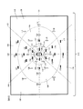
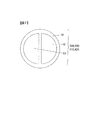
図2は撮像素子212の平面図である。撮像素子212は、行方向とそれに直交する方向の列方向に二次元正方配列された撮像画素と焦点検出画素から構成される。すなわち、撮像画素は行方向と列方向に稠密に配列されており、画素の稠密配列方向は行方向と列方向になる。図2において、点100は撮像素子212の撮影画面の中心、すなわち交換レンズ202の光軸と撮像素子212の撮影画面との交点であり、直線101は画面中心100を通る行方向(水平方向)の直線であり、直線102は画面中心100を通る列方向(垂直方向)の直線である。また、直線103は画面中心100を中心に直線101を反時計方向に45度回転した直線であり、直線104は画面中心100を中心に直線101を反時計方向に45度回転した直線である。
FIG. 2 is a plan view of the
撮像素子212の撮影画面は、画面中心100から放射方向に延びる直線103と直線104を境界線として4つの区域に分割され、区域110と区域130は点100に対し行方向(図の左右方向)の右方向と左方向に広がる区域であり、区域150と区域170は画面中心100に対し列方向(図の上下方向)の上方向と下方向に広がる区域である。また、図2に破線で示す楕円105、106は画面中心100を中心とした楕円であり、画面中心100を含む楕円105の内側が画面中心近傍の領域107であり、楕円105の外側でかつ楕円106の内側の領域は中間的な領域108であり、楕円106の外側の領域は画面周辺の領域109である。
The imaging screen of the
図2において、小さな長方形で示す領域に焦点検出画素が配列されており、この領域が焦点検出領域(焦点検出エリア)となる。長方形の長手方向が焦点検出画素の配列方向を示しており、焦点検出画素が列方向に配列された領域を白抜きの長方形で示し、焦点検出画素が行方向に配列された領域を黒く塗りつぶした長方形で示す。長方形の長手方向の長さは焦点検出領域の長さ(焦点検出画素の配列画素数)を示しており、領域122、142、162、182は他の領域よりその長さが短く設定されている。焦点検出領域以外には撮像画素が配列されており、複数の焦点検出領域の間の領域は撮像画素のみの領域となっている。
In FIG. 2, focus detection pixels are arranged in a region indicated by a small rectangle, and this region becomes a focus detection region (focus detection area). The longitudinal direction of the rectangle indicates the arrangement direction of the focus detection pixels, the area where the focus detection pixels are arranged in the column direction is indicated by a white rectangle, and the area where the focus detection pixels are arranged in the row direction is blacked out Shown as a rectangle. The length in the longitudinal direction of the rectangle indicates the length of the focus detection area (the number of pixels of the focus detection pixels), and the
画面中心100に対して水平方向の右にある区域110内では、画面中心近傍領域107に、焦点検出画素が垂直方向に配列された焦点検出領域111、112、113と、焦点検出画素が水平方向に配列された焦点検出領域121とが配置される。また、中間領域108には、焦点検出画素が垂直方向に配列された焦点検出領域114、115、116と、焦点検出画素が水平方向に配列された焦点検出領域122とが配置される。さらに、周辺領域109には、焦点検出画素が垂直方向に配列された焦点検出領域117、118、119が配置され、焦点検出画素が水平方向に配列された焦点検出領域は配置されない。
In an
画面中心100に対して水平方向の左にある区域130内では、画面中心近傍領域107に、焦点検出画素が垂直方向に配列された焦点検出領域131、132、133と、焦点検出画素が水平方向に配列された焦点検出領域141とが配置される。また、中間領域108には、焦点検出画素が垂直方向に配列された焦点検出領域134、135、136と、焦点検出画素が水平方向に配列された焦点検出領域142ととが配置される。さらに、周辺領域109には、焦点検出画素が垂直方向に配列された焦点検出領域137、138、139が配置され、焦点検出画素が水平方向に配列された焦点検出領域は配置されない。
In an
画面中心100に対して垂直方向の上にある区域150内では、画面中心近傍領域107に、焦点検出画素が水平方向に配列された焦点検出領域151、152、153と、焦点検出画素が垂直方向に配列された焦点検出領域161とが配置される。また、中間領域108には、焦点検出画素が水平方向に配列された焦点検出領域154、155、156と、焦点検出画素が垂直方向に配列された焦点検出領域162とが配置される。さらに、周辺領域109には、焦点検出画素が水平方向に配列された焦点検出領域157、158、159が配置され、焦点検出画素が垂直方向に配列された焦点検出領域は配置されない。
In an
画面中心100に対して垂直方向の下にある区域170内では、画面中心近傍領域107に、焦点検出画素が水平方向に配列された焦点検出領域171、172、173と、焦点検出画素が垂直方向に配列された焦点検出領域181とが配置される。また、中間領域108には、焦点検出画素が水平方向に配列された焦点検出領域174、175、176と、焦点検出画素が垂直方向に配列された焦点検出領域182が配置される。さらに、周辺領域109には、焦点検出画素が水平方向に配列された焦点検出領域177、178、179が配置され、焦点検出画素が垂直方向に配列された焦点検出領域は配置されない。
In an
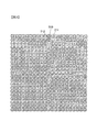
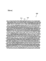
図3は撮像素子212の撮像画素配列の拡大図である。なお、図3では撮像画素のみの領域を拡大して示す。撮像画素は緑画素310、赤画素311、青画素312の3種類の画素からなり、これらの画素がベイヤー配列で2次元配列されている。図6に示すように撮像画素(緑画素310、赤画素311、青画素312)は、マイクロレンズ10、光電変換部11、不図示の色フィルタから構成される。色フィルタは赤(R)、緑(G)、青(B)の3種類からなり、それぞれの分光感度は図9に示す特性になっている。
FIG. 3 is an enlarged view of the imaging pixel array of the
図4と図5は撮像素子212の焦点検出画素配列の拡大図である。なお、図4は、図2において焦点検出画素が行方向に配列された領域(黒く塗りつぶした長方形で示す領域)を拡大して示す。図4において、焦点検出画素320は行方向に連続的に配列され、焦点検出領域を形成する。焦点検出画素320の配列の周囲は撮像画素により取り囲まれている。また、図5は、図2において焦点検出画素が列方向に配列された領域(白抜きの長方形で示す領域)を拡大して示す。図5において、焦点検出画素330は列方向に連続的に配列され、焦点検出領域を形成する。焦点検出画素330の配列の周囲は撮像画素により取り囲まれている。
4 and 5 are enlarged views of the focus detection pixel array of the
図7に示すように焦点検出画素320、330は、マイクロレンズ10、一対の光電変換部12,13から構成される。焦点検出画素330は、焦点検出画素320を90度回転した構成となっている。なお、図8に示すように、面積の小さな一対の光電変換部14,15を用いて焦点検出画素を構成することもでき、この種の焦点検出画素340,350については後述する。焦点検出画素320、330には光量をかせぐために色フィルタは配置されておらず、その分光特性は光電変換を行うフォトダイオードの分光感度、赤外カットフィルタ(不図示)の分光特性を総合した図10に示す分光特性となる。この焦点検出画素320,330の分光特性は、図9に示す緑画素、赤画素、青画素の分光特性を加算したような分光特性となり、その感度の光波長領域は緑画素、赤画素、青画素の感度の光波長領域を包括している。
As shown in FIG. 7, the
図6に示す撮像画素の光電変換部11は、マイクロレンズ10により所定の絞り開口径(例えばF1.0)の光束をすべて受光するような形状に設計される。一方、図7に示す焦点検出画素の一対の光電変換部12、13は、マイクロレンズ10により所定の絞り開口径(例えばF2.8)の光束をすべて受光するような形状に設計される。撮像により画像データを得る場合には、撮像画素の画像データをそのまま使用する。焦点検出画素位置における画像データは、焦点検出画素の近傍周囲にある撮像画素の画像データにより補間される。
The
例えば、図4と図5において、撮像画素の青画素があるべき位置に配置された焦点検出画素の位置の画像データは、この焦点検出画素の右隣(上隣)の緑画素を挟んで一つ右隣(上隣)の青画素の画像データと、この焦点検出画素の左隣(下隣)の緑画素を挟んで一つ左隣(下隣)の青画素の画像データとの平均として補間される。また、撮像画素の緑画素があるべき位置に配置された焦点検出画素の位置の画像データは、この焦点検出画素の斜め右上、右下、左上、左下45度方向の隣にある4つの緑画素の画像データの平均として補間される。 For example, in FIGS. 4 and 5, the image data at the position of the focus detection pixel arranged at the position where the blue pixel of the imaging pixel should be located is sandwiched between the green pixels on the right side (upper side) of the focus detection pixel. As the average of the image data of the blue pixel next to the right (upper next) and the image data of the blue pixel one left next (lower adjacent) across the green pixel to the left of the focus detection pixel (lower adjacent) Interpolated. Further, the image data at the position of the focus detection pixel arranged at the position where the green pixel of the image pickup pixel should be includes four green pixels adjacent to the focus detection pixel in the upper right, lower right, upper left, and lower left 45 degrees directions. Is interpolated as the average of the image data.
図11は撮像画素の断面図である。撮像画素において、撮像用の光電変換部11の前方にマイクロレンズ10が配置され、マイクロレンズ10により光電変換部11が前方に投影される。光電変換部11は半導体回路基板29上に形成される。なお、色フィルタ(不図示)はマイクロレンズ10と光電変換部11の中間に配置される。
FIG. 11 is a cross-sectional view of the imaging pixel. In the imaging pixel, the
図12は焦点検出画素の断面図である。焦点検出画素において、焦点検出用の光電変換部12、13の前方にマイクロレンズ10が配置され、マイクロレンズ10により光電変換部12、13が前方に投影される。光電変換部12、13は半導体回路基板29上に形成される。
FIG. 12 is a cross-sectional view of the focus detection pixel. In the focus detection pixel, the
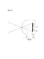
図13はマイクロレンズを用いた瞳分割方式による焦点検出の説明図である。90は、交換レンズの予定結像面に配置されたマイクロレンズの前方d0の距離に設定される射出瞳である。距離d0は、マイクロレンズの曲率、屈折率、マイクロレンズと光電変換部の間の距離などに応じて決まる“測距瞳距離”である。50、60はマイクロレンズ、(52,53)、(62,63)は焦点検出画素の一対の光電変換部、(72,73)、(82,83)は焦点検出用光束である。また、92はマイクロレンズ50、60により投影された光電変換部52、62の領域(以下では測距瞳と呼ぶ)、93はマイクロレンズ50、60により投影された光電変換部53、63の領域(測距瞳)である。
FIG. 13 is an explanatory diagram of focus detection by a pupil division method using a microlens.
図13では、便宜的に光軸上にある焦点検出画素(マイクロレンズ50と一対の光電変換部52、53からなる)と、隣接する焦点検出画素(マイクロレンズ60と一対の光電変換部62、63からなる)とを模式的に例示しているが、焦点検出画素が画面周辺の光軸から離れた位置にあった場合においても、一対の光電変換部はそれぞれ一対の測距瞳から各マイクロレンズに到来する光束を受光する。焦点検出画素の配列方向は、一対の測距瞳の並び方向、すなわち一対の光電変換部の並び方向と一致させる。
In FIG. 13, for convenience, a focus detection pixel (consisting of a
マイクロレンズ50、60は光学系の予定結像面近傍に配置されており、マイクロレンズ50によりその背後に配置された一対の光電変換部52、53の形状がマイクロレンズ50、60から投影距離d0だけ離間した射出瞳90上に投影され、その投影形状は測距瞳92,93を形成する。また、マイクロレンズ60によりその背後に配置された一対の光電変換部62、63の形状が投影距離d0だけ離間した射出瞳90上に投影され、その投影形状は測距瞳92,93を形成する。すなわち、投影距離d0にある射出瞳90上で各焦点検出画素の光電変換部の投影形状(測距瞳92,93)が一致するように、各画素の投影方向が決定されている。換言すれば、一対の測距瞳92,93と一対の光電変換部(52,53)はマイクロレンズ50を介して、一対の測距瞳92,93と一対の光電変換部(62,63)はマイクロレンズ60を介して、それぞれ共役な関係になっている。
The
光電変換部52は測距瞳92を通過し、マイクロレンズ50に向う焦点検出用光束72によりマイクロレンズ50上に形成される像の強度に対応した信号を出力する。光電変換部53は測距瞳93を通過し、マイクロレンズ50に向う焦点検出用光束73によりマイクロレンズ50上に形成される像の強度に対応した信号を出力する。光電変換部62は測距瞳92を通過し、マイクロレンズ60に向う焦点検出用光束82によりマイクロレンズ60上に形成される像の強度に対応した信号を出力する。光電変換部63は測距瞳93を通過し、マイクロレンズ60に向う焦点検出用光束83によりマイクロレンズ60上に形成される像の強度に対応した信号を出力する。
The
上記のような焦点検出画素を直線状に複数個配置し、各画素の一対の光電変換部の出力を測距瞳92および測距瞳93に対応した出力グループにまとめることによって、測距瞳92と測距瞳93をそれぞれ通過する焦点検出用光束が焦点検出画素列上に形成する一対の像の強度分布に関する情報が得られる。これらの情報に対して後述する像ズレ検出演算処理(相関演算処理、位相差検出処理)を施すことによって、いわゆる瞳分割型位相差検出方式で一対の像の像ズレ量が検出される。つまり、像ズレ量に一対の測距瞳の重心間隔に応じた変換演算を行うことによって、予定結像面に対する現在の結像面(予定結像面上のマイクロレンズアレイの位置に対応した焦点検出位置における結像面)の偏差(デフォーカス量)が算出される。
A plurality of focus detection pixels as described above are arranged in a straight line, and the output of a pair of photoelectric conversion units of each pixel is collected into an output group corresponding to the
なお、上記説明では、測距瞳が交換レンズの開口制限要素(絞り開口、レンズ外形、フードなど)によって制限されていない(けられていない)状態として説明を行ったが、交換レンズの開口制限要素によって測距瞳が制限される場合には、焦点検出画素の光電変換部は制限を受けた測距瞳を通過する光束を焦点検出用光束として受光することになる。 In the above description, the range-finding pupil has been described as being not limited by the aperture limiting elements (aperture aperture, lens outer shape, hood, etc.) of the interchangeable lens. When the distance measuring pupil is limited by the element, the photoelectric conversion unit of the focus detection pixel receives the light beam passing through the limited distance measuring pupil as the focus detection light beam.
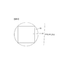
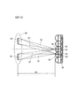
図14は、画面中心から離れた焦点検出領域における測距瞳のケラレの説明図である。図14に示すように、焦点検出領域の位置が予定焦点面P0に設定された画面周辺のSにある場合に、射出瞳90にある絞り開口97によって測距瞳92,93にケラレは生じていないが、射出瞳面90より遠方にある面99に存在する開口制限要素98(開口絞り、レンズ端など)によって測距瞳92にケラレが生じる。測距瞳92、93に対して、開口制限要素98の開口が、画面中心と焦点検出位置Sとを結ぶ方向に、画面中心と焦点検出位置Sとの間の距離に応じた量だけずれる。
FIG. 14 is an explanatory diagram of vignetting of a distance measuring pupil in a focus detection area away from the center of the screen. As shown in FIG. 14, when the position of the focus detection region is in S around the screen set to the planned focal plane P0, vignetting is generated in the
図15は撮像画素と射出瞳の関係を説明する図である。なお、図13に示す要素と同様な要素に対しては同一の符号を付して説明する。70はマイクロレンズ、71は撮像画素の光電変換部、81は撮像用光束である。また、94はマイクロレンズ70により投影された光電変換部71の領域である。図15では、光軸上にある撮像画素(マイクロレンズ70と光電変換部71からなる)を模式的に例示しているが、その他の撮像画素においても光電変換部はそれぞれ領域94から各マイクロレンズに到来する光束を受光する。
FIG. 15 is a diagram illustrating the relationship between the imaging pixels and the exit pupil. In addition, the same code | symbol is attached | subjected and demonstrated to the element similar to the element shown in FIG.
マイクロレンズ70は光学系の予定結像面近傍に配置されており、マイクロレンズ70によりその背後に配置された光電変換部71の形状がマイクロレンズ70から投影距離d0だけ離間した射出瞳90上に投影され、その投影形状は領域94を形成する。光電変換部71は領域94を通過し、マイクロレンズ70に向う撮像用光束81によりマイクロレンズ70上に形成される像の強度に対応した信号を出力する。上記のような撮像画素を2次元状に多数配置することにより、各画素の光電変換部に基づいて画像情報が得られる。
The
図16および図17は射出瞳面における測距瞳の正面図であり、焦点検出領域の位置Sが図2に示す画面中心に対して水平方向に分離した領域110および領域130の中にある場合の、測距瞳のケラレの様子を示す。図16において、焦点検出画素320から一対の光電変換部をマイクロレンズにより射出瞳面90に投影した測距瞳922,933の外接円は、結像面から見た場合に所定の開口F値(以下では測距瞳F値と呼ぶ。ここではF2.8)となる。破線で示す領域901は、絞り値F2.8よりも大きな絞り値(例えばF2)に対応した領域を示し、測距瞳922,933を内部に含んでいる。測距瞳922,933の並び方向(図では左右方向)における測距瞳922、933を通過する光束(焦点検出用光束)の重心952,953の間隔は、G1となる。
16 and 17 are front views of the distance measuring pupil on the exit pupil plane, and the position S of the focus detection region is in the
図14に示すような焦点検出用光束のケラレが発生した場合には、開口制限による開口が測距瞳に対して水平方向にずれて重ね合わされる(領域903は開口制限の一部を示している)。このような状態では測距瞳922が領域903によりけられており、領域903によって制限された測距瞳922を通過する光束(焦点検出用光束)の重心972は、けられていない場合の重心952より中心に偏っている。一方、測距瞳933は領域903によりけられず、測距瞳922を通過する光束(焦点検出用光束)の重心953の位置は変化しない。したがって、測距瞳重心972と953の間隔は、ケラレが生じていない場合の重心間隔G1より狭い重心間隔G1’となる。
When the vignetting of the focus detection light beam as shown in FIG. 14 occurs, the aperture due to the aperture limitation is overlapped with the distance measurement pupil in the horizontal direction (
また、ケラレにより測距瞳の面積の比がアンバランスになり、結果的に一対の測距瞳によって形成される一対の像の強度比がアンバランスになり、一致性(同一性)が崩れるために焦点検出精度が低下し、ケラレの程度が大きい場合には焦点検出不能になってしまう。一般的に、ケラレの程度は画面中心から焦点検出領域までの距離に比例して大きくなる。 In addition, the ratio of the area of the distance measuring pupil becomes unbalanced due to vignetting, and as a result, the intensity ratio of the pair of images formed by the pair of distance measuring pupils becomes unbalanced, and the coincidence (identity) is lost. However, when the focus detection accuracy is lowered and the degree of vignetting is large, focus detection becomes impossible. In general, the degree of vignetting increases in proportion to the distance from the center of the screen to the focus detection area.
図17において、焦点検出画素330から一対の光電変換部をマイクロレンズにより射出瞳面90に投影した測距瞳822,833の外接円は、結像面から見た場合に所定の開口F値(測距瞳F値、ここではF2.8)となる。破線で示す領域901は、絞り値F2.8よりも大きな絞り値(例えばF2)に対応した領域を示し、測距瞳822,833を内部に含んでいる。測距瞳822,823の並び方向(図では上下方向)における測距瞳822、833を通過する光束(焦点検出用光束)の重心852,853の間隔は、G2(=G1)となる。図14に示すような焦点検出用光束のケラレが発生した場合には、開口制限による開口が測距瞳に対して水平方向にずれて重ね合わされる(領域903は開口制限の一部を示している)。
In FIG. 17, the circumscribed circle of the
このような状態では、測距瞳822と測距瞳823の右端部分が領域903によりけられているが、そのケラレが測距瞳822,823に対称的に発生しているので領域903によって測距瞳822,823の重心位置852,853はほとんど変化せず、したがって、測距瞳822,823を通過する光束(焦点検出用光束)の重心852、853の間隔G2は変化しない。また、ケラレた場合でも一対の測距瞳の面積は等しいので、一対の測距瞳によって形成される一対の像の一致性(同一性)も維持され、焦点検出精度が低下することはない。
In such a state, the right end portions of the
以上説明したように、図2において、画面中心100に対して水平方向に分離した区域110と区域130では、焦点検出画素330を垂直方向に配列した焦点検出領域の方が焦点検出画素320を水平方向に配列した焦点検出領域に比較して焦点検出性能を維持し易い。逆に、図2において、画面中心100に対して垂直方向に分離した区域150と区域170では、焦点検出画素320を水平方向に配列した焦点検出領域の方が焦点検出画素330を垂直方向に配列した焦点検出領域に比較して焦点検出性能を維持し易い。
As described above, in the
次に、図2に示す撮像素子212の構成、特に焦点検出領域の配置についての特徴を説明する。まず、区域110、130、150,170の各区域に、焦点検出画素320を水平方向に配列した焦点検出領域と、焦点検出画素330を垂直方向に配列した焦点検出領域とをそれぞれ複数配置することによって、焦点検出対象を画面上において可能な限り多くの位置で捕捉できるとともに、像コントラストの方向による焦点検出性能の低下を防止できる。
Next, the characteristics of the configuration of the
また、焦点検出対象が存在する可能性の高い画面中心領域107では、焦点検出画素320と焦点検出画素330、あるいは焦点検出画素320を水平方向に配列した焦点検出領域と、焦点検出画素330を垂直方向に配列した焦点検出領域とを、中間領域108および周辺領域109に比べ単位面積あたりの密度を高くして配置することによって、焦点検出画素数を制限しながら焦点検出性能を効率的に達成できるように焦点検出画素320と焦点検出画素330を配分することができる。
Further, in the
さらに、画面中心に対して水平方向に分離した区域110と区域130では、焦点検出画素330の数を焦点検出画素320の数より多くするとともに、画面中心に対して垂直方向に分離した区域150と区域170では、焦点検出画素320の数を焦点検出画素330の数より多くすることによって、ケラレに対する焦点検出性能維持を図り、焦点検出画素数を制限しながら焦点検出性能を効率的に達成できるように焦点検出画素320と焦点検出画素330を配分することができる。
Further, in
画面中心に対して水平方向に分離した区域110と区域130では、焦点検出画素330を垂直方向に配列した焦点検出領域の数が、焦点検出画素320を水平方向に配列した焦点検出領域の数より多くなるようにするともに、画面中心に対して垂直方向に分離した区域150と区域170では、焦点検出画素320を水平方向に配列した焦点検出領域の数が、焦点検出画素330を垂直方向に配列した焦点検出領域の数より多くなるようにすることによって、ケラレに対する焦点検出性能維持を図り、焦点検出画素数を制限しながら焦点検出性能を効率的に達成できるように焦点検出画素320と焦点検出画素330を配分することができる。
In the
一方、画面中心近傍においては焦点検出性能に与えるケラレの影響は少なく、画面中心から離れるにつれてその影響が増大するので、画面中心に対して水平方向の左右にある区域110、130内においては、画面中心からの距離が大きくなるにつれて、焦点検出画素320および焦点検出画素320を水平方向に配列した焦点検出領域の数を少なくするとともに、単位面積当たりの密度を低くしている。また、焦点検出画素330および焦点検出画素330を垂直方向に配列した焦点検出領域の数および密度との相対比も画面中心から離れるにつれて小さくなるようにしている。
On the other hand, the influence of vignetting on the focus detection performance is small in the vicinity of the screen center, and the influence increases as the distance from the screen center increases. As the distance from the center increases, the number of
画面中心に対して垂直方向の上下にある区域150、170内においては、画面中心からの距離が大きくなるにつれて、焦点検出画素330および焦点検出画素330を垂直方向に配列した焦点検出領域の数を少なくするとともに、単位面積当たりの密度を低くしている。また、焦点検出画素320および焦点検出画素320を水平方向に配列した焦点検出領域の数および密度との相対比も画面中心から離れるにつれて小さくなるようにしている。これにより、ケラレに対する焦点検出性能維持を図り、焦点検出画素数を制限しながら焦点検出性能を効率的に達成できるように焦点検出画素320と焦点検出画素330を配分することができる。
In the
画面中心に対して水平方向の左右にある区域110、130内においては、周辺領域に焦点検出性能がケラレの影響を受けにくい焦点検出画素330を垂直方向に配列した焦点検出領域のみを配置している。一方、画面中心に対して垂直方向の上下にある区域150、170内においては、周辺領域に焦点検出性能がケラレの影響を受けにくい焦点検出画素320を水平方向に配列した焦点検出領域のみを配置している。結果的に、複数の焦点検出領域を包括する範囲の水平方向の外周領域においては、焦点検出画素330を垂直方向に配列した焦点検出領域のみが配置され、一方、垂直方向の外周領域においては、焦点検出画素320を水平方向に配列した焦点検出領域のみが配置される。これにより、ケラレに対する焦点検出性能維持を図り、焦点検出画素数を制限しながら焦点検出性能を効率的に達成できるように焦点検出画素320と焦点検出画素330を配分することができる。
In the
図18は、図1に示すデジタルスチルカメラ(撮像装置)の動作を示すフローチャートを示す。ボディ駆動制御装置214は、ステップ100でカメラの電源がオンされると撮像動作を開始する。ステップ110で、測光装置(不図示)により測光した被写界輝度に応じて自動的に決定された撮影絞り値、あるいは操作部材(不図示)によって撮影者が手動で設定した撮影絞り値に応じた絞り制御情報をレンズ駆動制御装置206へ送り、絞り開口径を撮影絞り値に設定し、この絞り開口径にて撮像画素のデータを間引き読み出しし、電子ビューファインダーに表示させる。
FIG. 18 is a flowchart showing the operation of the digital still camera (imaging device) shown in FIG. When the camera is turned on in
ステップ120において、絞り開口径が撮影絞り値に設定された状態で焦点検出画素列からデータを読み出す。続くステップ130では、焦点検出画素列に対応した一対の像データに基づいて後述する像ズレ検出演算処理(相関演算処理)を行い、像ズレ量を演算し、さらにデフォーカス量を算出する。なお、焦点検出に用いる焦点検出領域は撮影者により選択される。ステップ140で合焦近傍か否か、つまり算出されたデフォーカス量の絶対値が所定値以内であるか否かを判別する。合焦近傍でないと判別された場合はステップ150へ進み、デフォーカス量をレンズ駆動制御装置206へ送信し、交換レンズのフォーカシングレンズを合焦位置に駆動させ、ステップ110へ戻って上記動作を繰り返す。焦点検出不能な場合もこのステップに分岐し、レンズ駆動制御装置206へスキャン駆動命令を送信し、交換レンズのフォーカシングレンズを無限から至近間でスキャン駆動させ、ステップ110へ戻って上記動作を繰り返す。
In step 120, data is read from the focus detection pixel array with the aperture diameter set to the photographing aperture value. In
一方、ステップ140で合焦近傍であると判別された場合はステップ160へ進み、レリーズボタン(不図示)の操作によりシャッターレリーズがなされたか否かを判別し、なされていない場合はステップ110へ戻って上記動作を繰り返す。シャッターレリーズがなされた場合はステップ170へ進み、レンズ駆動制御装置206へ絞り制御情報を送信し、交換レンズの絞り値を撮影絞り値にする。絞り制御が終了した時点で、撮像素子に撮像動作を行わせ、撮像素子の撮像画素および全ての焦点検出画素から画像データを読み出す。ステップ180で、焦点検出画素列の各画素位置の画素データを周囲の撮像画素のデータに基づいて補間し、続くステップ190で、撮像画素のデータおよび補間されたデータからなる画像データをメモリーカードに保存し、ステップ110へ戻って上記動作を繰り返す。
On the other hand, if it is determined in step 140 that the focus is close to the in-focus state, the process proceeds to step 160, where it is determined whether or not a shutter release has been performed by operating a release button (not shown), and if not, the process returns to step 110. Repeat the above operation. If the shutter release has been performed, the process proceeds to step 170, where aperture control information is transmitted to the lens
ここで、図18のステップ130の像ズレ検出演算処理(相関演算処理)について説明する。焦点検出画素列から出力される一対のデータ列(α1〜αM、β1〜βM:Mはデータ数)に対し、下記(1)式に示すような高周波カットフィルタ処理を施し、第1データ列、第2データ列(A1〜AN、B1〜BN)を生成することによって、データ列から相関処理に悪影響を及ぼすノイズ成分や高周波成分を除去する。α1〜αMは、図13において、測距瞳92を通る焦点検出光束により形成される像の画像データに相当し、β1〜βMは、測距瞳93を通る焦点検出光束により形成される像の画像データに相当する。なお、演算時間の短縮を図る場合や、すでに大きくデフォーカスしていて高周波成分が少ないことがわかっている場合などには、この処理を省略することもできる。
An=αn+2×αn+1+αn+2,
Bn=βn+2×βn+1+βn+2 ただし、n=1〜N ・・・(1)
Here, the image shift detection calculation process (correlation calculation process) in
An = αn + 2 × αn + 1 + αn + 2,
Bn = βn + 2 × βn + 1 + βn + 2 where n = 1 to N (1)
(1)式により求められたデータ列An、Bnに対し、(2)式に示す相関演算を行い、相関量C(k)を演算する
C(k)=Σ|An−Bn+k| ・・・(2)
(2)式において、Σ演算はnについて累積され、nのとる範囲はずらし量kに応じてAn、Bn+kのデータが存在する範囲に限定される。ずらし量kは整数であり、データ列のデータ間隔(画素ピッチ)を単位とした相対的シフト量である。(2)式の演算結果は、図19(a)に示すように、一対のデータの相関が高いシフト量(図19(a)ではk=kj=2)において相関量C(k)が極小(小さいほど相関度が高い)になる。
The correlation calculation shown in the equation (2) is performed on the data strings An and Bn obtained by the equation (1) to calculate the correlation amount C (k). C (k) = Σ | An−Bn + k | (2)
In equation (2), the Σ operation is accumulated for n, and the range taken by n is limited to the range in which the data of An and Bn + k exist according to the shift amount k. The shift amount k is an integer and is a relative shift amount with the data interval (pixel pitch) of the data string as a unit. As shown in FIG. 19A, the calculation result of the expression (2) shows that the correlation amount C (k) is minimal in the shift amount with high correlation between a pair of data (k = kj = 2 in FIG. 19A). (The smaller the value, the higher the degree of correlation).
次に、(3)式〜(6)式による3点内挿の手法を用いて連続的な相関量に対する極小値C(x)を与えるシフト量xを求める。
x=kj+D/SLOP ・・・(3),
C(x)= C(kj)-|D| ・・・(4),
D={C(kj-1)−C(kj+1)}/2 ・・・(5),
SLOP=MAX{C(kj+1)−C(kj),C(kj-1)−C(kj)} ・・・(6)
(3)式で算出されたずらし量xの信頼性があるかどうかは、以下のようにして判定される。図19(b)に示すように、一対のデータの相関度が低い場合は、内挿された相関量の極小値C(x)の値が大きくなる。したがって、C(x)が所定の閾値以上の場合は算出されたずらし量の信頼性が低いと判定し、算出されたずらし量xをキャンセルする。あるいは、C(x)をデータのコントラストで規格化するために、コントラストに比例した値となるSLOPでC(x)を除した値が所定値以上の場合は、算出されたずらし量の信頼性が低いと判定し、算出されたずらし量xをキャンセルする。あるいはまた、コントラストに比例した値となるSLOPが所定値以下の場合は、被写体が低コントラストであり、算出されたずらし量の信頼性が低いと判定し、算出されたずらし量xをキャンセルする。図19(c)に示すように、一対のデータの相関度が低く、シフト範囲kmin〜kmaxの間で相関量C(x)の落ち込みがない場合は、極小値C(x)を求めることができず、このような場合は焦点検出不能と判定する。
Next, a shift amount x that gives a minimum value C (x) with respect to a continuous correlation amount is obtained using a three-point interpolation method according to equations (3) to (6).
x = kj + D / SLOP (3),
C (x) = C (kj)-| D | (4),
D = {C (kj-1) -C (kj + 1)} / 2 (5),
SLOP = MAX {C (kj + 1) -C (kj), C (kj-1) -C (kj)} (6)
Whether or not the shift amount x calculated by the equation (3) is reliable is determined as follows. As shown in FIG. 19B, when the degree of correlation between a pair of data is low, the value of the minimal value C (x) of the interpolated correlation amount increases. Accordingly, when C (x) is equal to or greater than a predetermined threshold value, it is determined that the calculated shift amount has low reliability, and the calculated shift amount x is canceled. Alternatively, in order to normalize C (x) with the contrast of data, when the value obtained by dividing C (x) by SLOP that is proportional to the contrast is equal to or greater than a predetermined value, the reliability of the calculated shift amount Is determined to be low, and the calculated shift amount x is canceled. Alternatively, when SLOP that is a value proportional to the contrast is equal to or less than a predetermined value, it is determined that the subject has low contrast and the reliability of the calculated shift amount is low, and the calculated shift amount x is canceled. As shown in FIG. 19C, when the degree of correlation between the pair of data is low and there is no drop in the correlation amount C (x) between the shift ranges kmin to kmax, the minimum value C (x) is obtained. In such a case, it is determined that the focus cannot be detected.
算出されたずらし量xの信頼性があると判定された場合は、被写体像面の予定結像面に対するデフォーカス量DEFを(7)式で求めることができる。
DEF=KX・PY・x ・・・(7)
(7)式において、PYは検出ピッチ(焦点検出画素のピッチ)であり、KXは一対の測距瞳を通過する光束の重心の開き角の大きさ(測距瞳重心間隔と測距瞳距離によって決まる)によって決まる変換係数である。
When it is determined that the calculated shift amount x is reliable, the defocus amount DEF of the subject image plane with respect to the planned image formation plane can be obtained by Expression (7).
DEF = KX · PY · x (7)
In equation (7), PY is a detection pitch (pitch of focus detection pixels), and KX is a size of an opening angle of the center of gravity of a light beam passing through a pair of distance measurement pupils (range of distance pupil center of gravity and distance pupil distance). Conversion coefficient determined by
なお、以上の説明では複数の焦点検出領域の中から所定の焦点検出領域が予め選択されているとしたが、複数の焦点検出領域で同時に焦点検出を行い、算出された複数の焦点検出結果に基づき、所定のアルゴリズム(例えば平均処理)により最終的な焦点検出結果を求めるようにしてもよい。 In the above description, a predetermined focus detection area is selected in advance from a plurality of focus detection areas. However, focus detection is simultaneously performed in the plurality of focus detection areas, and the calculated multiple focus detection results are obtained. Based on this, a final focus detection result may be obtained by a predetermined algorithm (for example, an average process).
《発明の一実施の形態の変形例》
図20および図21は、変形例の撮像素子212Aにおける焦点検出画素配列の拡大図である。上述した図4、図5に示す一実施の形態の撮像素子212では、1つの焦点検出画素が一対の測距瞳に対応する一対の光電変換部を備えている例を示したが、この変形例の撮像素子212Aでは、1つの焦点検出画素が一対の測距瞳の片方に対応する一つの光電変換部を備えるとともに、隣接する焦点検出画素が一対の測距瞳のもう一方に対応する一つの光電変換部を備え、対となった焦点検出画素を配列することによって焦点検出領域を形成する。図20および図21は、このようにして形成された焦点検出画素が配列された領域を拡大した図である。
<< Modification of Embodiment of Invention >>
20 and 21 are enlarged views of the focus detection pixel array in the
図20は、図2において焦点検出画素が行方向に配列された領域(黒く塗りつぶした長方形で示す領域)に対応しており、図21は図2において焦点検出画素が列方向に配列された領域(白抜きの長方形で示す領域)に対応している。図20において、焦点検出画素321、322のペアは行方向に連続的に配列され、焦点検出領域を形成する。焦点検出画素321、322の配列の周囲は撮像画素により取り囲まれている。一方、図21において、焦点検出画素331、332のペアは列方向に連続的に配列され、焦点検出領域を形成する。焦点検出画素331、332の配列の周囲は撮像画素により取り囲まれている。以上のように焦点検出画素が1つの光電変換部を備えるように構成することによって、単位画素の回路構成が撮像画素の回路構成と同一にできるので、撮像素子全体の回路をシンプルに構成することができる。
20 corresponds to an area in which focus detection pixels are arranged in the row direction in FIG. 2 (an area indicated by a black rectangle), and FIG. 21 is an area in which focus detection pixels are arranged in the column direction in FIG. (Region indicated by a white rectangle). 20, pairs of
次に、図2に示す撮像素子において、焦点検出画素320、330の一部を図8に示す焦点検出画素340、350に置換することができる。図8に示す焦点検出画素340、350の構成は図7に示す焦点検出画素の構成と同様であり、一対の光電変換部14、15のサイズが光電変換部12、13よりも小さくなっているだけである。焦点検出画素350は焦点検出画素340を90度回転した構成となっている。
Next, in the image sensor shown in FIG. 2, a part of the
図22は、図8に示す焦点検出画素の射出瞳面における測距瞳の正面図であり、焦点検出画素340が図2の画面中心に対して水平方向に離間した位置にある場合の測距瞳のケラレの様子を示す。図において、焦点検出画素340から一対の光電変換部をマイクロレンズにより射出瞳面90に投影した測距瞳722,733の外接円は、結像面から見た場合に所定の開口F値(測距瞳F値、ここではF5.6)となる。破線で示す領域901は、絞り値F2.8よりも大きな絞り値(例えばF2)に対応した領域を示し、測距瞳722,733を内部に含んでいる。測距瞳722,733の並び方向(図では左右方向)における測距瞳722、733を通過する光束(焦点検出光束)の重心752,753の間隔は、G3となる。
FIG. 22 is a front view of the distance measuring pupil on the exit pupil plane of the focus detection pixel shown in FIG. 8, and the distance measurement when the
図14に示すような焦点検出光束のケラレが発生した場合には、開口制限による開口が測距瞳に対して水平方向にずれて重ね合わされる(領域903は開口制限の一部を示している)。このような状態においても測距瞳722、733のサイズが小さいので、領域903によりけられにくくなり、図2に示す中間領域108においても焦点検出性能を維持することが容易になる。したがって、図2において、焦点検出領域122、142を焦点検出画素340の配列により構成し、焦点検出領域162、182を焦点検出画素350の配列により構成することによって、中間領域においても焦点検出性能を維持することが可能になる。
When the vignetting of the focus detection light beam as shown in FIG. 14 occurs, the aperture due to the aperture limitation is overlapped with being shifted in the horizontal direction with respect to the distance measuring pupil (a
図23は変形例の撮像素子212Bの平面図である。図2に示す撮像素子212では、焦点検出画素が水平方向に配列された焦点検出領域と、焦点検出画素が垂直方向に配列された焦点検出領域とは位置的に分離して配置されていた。図23に示す変形例の撮像素子212Bでは、焦点検出画素が水平方向に配列された焦点検出領域と、焦点検出画素が垂直方向に配列された焦点検出領域とを同一位置に交差させて配置している。ここでは、図2に示す構成と同様な構成についての説明を省略し、相違点のみを説明する。
FIG. 23 is a plan view of an
画面中心100に対して水平方向の右にある区域110内において、画面中心近傍領域107には、焦点検出画素が垂直方向に配列された焦点検出領域125と、焦点検出画素が水平方向に配列された焦点検出領域123とが交差されて配置される。また、中間領域108には、焦点検出画素が垂直方向に配列された焦点検出領域126と、焦点検出画素が水平方向に配列された焦点検出領域124が交差されて配置される。一方、画面中心100に対して水平方向の左にある区域130内において、画面中心近傍領域107には、焦点検出画素が垂直方向に配列された焦点検出領域145と、焦点検出画素が水平方向に配列された焦点検出領域143とが交差されて配置され、中間領域108には、焦点検出画素が垂直方向に配列された焦点検出領域146と、焦点検出画素が水平方向に配列された焦点検出領域144とが交差されて配置される。
In an
画面中心100に対して垂直方向の上にある区域150内において、画面中心近傍領域107には、焦点検出画素が垂直方向に配列された焦点検出領域163と、焦点検出画素が水平方向に配列された焦点検出領域165とが交差されて配置され、中間領域108には、焦点検出画素が垂直方向に配列された焦点検出領域164と、焦点検出画素が水平方向に配列された焦点検出領域166とが交差されて配置される。画面中心100に対して垂直方向の下にある区域170内において、画面中心近傍領域107には、焦点検出画素が垂直方向に配列された焦点検出領域183と、焦点検出画素が水平方向に配列された焦点検出領域185とが交差されて配置され、中間領域108には、焦点検出画素が垂直方向に配列された焦点検出領域184と、焦点検出画素が水平方向に配列された焦点検出領域186とが交差されて配置される。
In an
図24は、図23に示す焦点検出領域123と焦点検出領域125とが交差した領域を拡大した図である。焦点検出領域123は焦点検出画素340の配列により形成され、焦点検出領域125は焦点検出画素330の配列により形成される。なお、交差位置には焦点検出画素330が配置される。焦点検出画素320の配列および焦点検出画素330の配列の周囲は、撮像画素により取り囲まれている。なお、焦点検出領域124と焦点検出領域126とが交差した領域、焦点検出領域143と焦点検出領域145とが交差した領域、焦点検出領域144と焦点検出領域146とが交差した領域も、同様な構成となる。
FIG. 24 is an enlarged view of a region where the
また、焦点検出領域163と焦点検出領域165とが交差した領域、焦点検出領域164と焦点検出領域166とが交差した領域、焦点検出領域183と焦点検出領域185とが交差した領域、焦点検出領域184と焦点検出領域186とが交差した領域も、同様な構成となるが、交差位置には焦点検出画素320が配置される。
Further, a region where the
以上のような構成により、画面上の同一位置で水平方向および垂直方向で焦点検出が可能になるので、焦点検出画素数を制限しながら焦点検出性能を効率的に達成できるように焦点検出画素320と焦点検出画素330を配分することができる。
With the configuration described above, focus detection can be performed in the horizontal direction and the vertical direction at the same position on the screen. Therefore, the
次に、図23に示す撮像素子212Bの構成、特に焦点検出領域の配置の特徴について説明する。区域110、130の各区域には、焦点検出画素320を水平方向に配列した焦点検出領域と、焦点検出画素330を垂直方向に配列した焦点検出領域とを交差させた焦点検出領域、および焦点検出画素330を垂直方向に配列した単独の焦点検出領域をそれぞれ複数配置する。また、区域150、170の各区域には、焦点検出画素320を水平方向に配列した焦点検出領域と、焦点検出画素330を垂直方向に配列した焦点検出領域とを交差させた焦点検出領域、および焦点検出画素320を水平方向に配列した単独の焦点検出領域をそれぞれ複数配置する。これにより、焦点検出対象を画面上において可能な限り多くの位置で捕捉できるようにするとともに、交差する焦点検出領域の存在により画面上の同一の位置において水平方向と垂直方向の像コントラストが同時に検出可能になり、焦点検出性能が向上する。
Next, the configuration of the
また、焦点検出対象が存在する可能性の高い画面中心領域107においては、焦点検出画素320を水平方向に配列した焦点検出領域と、焦点検出画素330を垂直方向に配列した焦点検出領域とを交差させた焦点検出領域のみを配置することによって、焦点検出性能の向上を図っている。
In the
さらに、ケラレの影響が出てくる中間領域108においては、焦点検出画素320を水平方向に配列した焦点検出領域と、焦点検出画素330を垂直方向に配列した焦点検出領域とを交差させた焦点検出領域、およびケラレの影響を受けにくい単独の焦点検出領域(区域110、130では焦点検出画素330を垂直方向に配列した焦点検出領域、区域150、170では焦点検出画素320を水平方向に配列した焦点検出領域)を配置することによって、焦点検出性能の維持を図っている。
Further, in the
ケラレの影響が大きくなる周辺領域109においては、ケラレの影響を受けにくい単独の焦点検出領域(区域110、130では焦点検出画素330を垂直方向に配列した焦点検出領域、区域150、170では焦点検出画素320を水平方向に配列した焦点検出領域)のみを配置することによって、焦点検出性能の維持を図っている。
In the
画面中心に対して水平方向に分離した区域110と130においては、焦点検出画素330の数を焦点検出画素320の数より多くするとともに、画面中心に対して垂直方向に分離した区域150と170においては、焦点検出画素320の数を焦点検出画素330の数より多くすることによって、ケラレに対する焦点検出性能維持を図り、焦点検出画素数を制限しながら焦点検出性能を効率的に達成できるように焦点検出画素320と焦点検出画素330を配分している。
In
画面中心に対して水平方向に分離した区域110と130においては、焦点検出画素330を垂直方向に配列した焦点検出領域の数を、焦点検出画素320を水平方向に配列した焦点検出領域の数より多くするともに、画面中心に対して垂直方向に分離した区域150と170においては、焦点検出画素320を水平方向に配列した焦点検出領域の数を、焦点検出画素330を垂直方向に配列した焦点検出領域の数より多くすることによって、ケラレに対する焦点検出性能維持を図り、焦点検出画素数を制限しながら焦点検出性能を効率的に達成できるように焦点検出画素320と焦点検出画素330を配分している。
In the
画面中心近傍においては焦点検出性能に与えるケラレの影響が少なく、画面中心から離れるにつれてその影響が増大するので、画面中心に対して水平方向の左右にある区域110と130の範囲内においては、ケラレの影響を受けやすい焦点検出画素320を水平方向に配列した焦点検出領域を、ケラレの影響を受けにくい焦点検出画素330を垂直方向に配列した焦点検出領域とペア(交差して)で使用するとともに、画面中心に対して垂直方向の上下にある区域150と170の範囲内においては、ケラレの影響を受けやすい焦点検出画素330を垂直方向に配列した焦点検出領域を、ケラレの影響を受けにくい焦点検出画素330を水平方向に配列した焦点検出領域とペア(交差して)で使用することによって、焦点検出画素数を制限しながら焦点検出性能の維持を図っている。
The influence of vignetting on the focus detection performance is small near the center of the screen, and the influence increases as the distance from the center of the screen increases. The focus detection area in which the
図25は、図24に示す焦点検出画素320の配列を、ケラレの影響を受けにくい図8に示す焦点検出画素340の配列に置換した例を示す。また、図26は、図24に示す焦点検出画素320の配列および焦点検出画素330の配列を、1画素あたりの光電変換部の数が1つの焦点検出画素321と322のペアの配列および焦点検出画素331と332のペアの配列に置換した例を示す。
FIG. 25 illustrates an example in which the array of
図2と図23に示す撮像素子では、撮像画素がベイヤー配列の色フィルタを備えた例を示したが、色フィルタの構成や配列はこれに限定されることはなく、補色フィルタ(緑:G、イエロー:Ye、マゼンタ:Mg,シアン:Cy)を採用してもよい。 In the image sensor shown in FIGS. 2 and 23, the example in which the image pickup pixel includes the Bayer color filter is shown. However, the configuration and arrangement of the color filter are not limited to this, and the complementary color filter (green: G Yellow: Ye, magenta: Mg, cyan: Cy) may be employed.
図2と図23に示す撮像素子では、焦点検出画素に色フィルタを設けない例を示したが、撮像画素と同色の色フィルタの内のひとつのフィルタ(例えば緑フィルタ)を備えるようにした場合でも、本発明を適用することができる。このようにすれば、画像データの補間において焦点検出画素の画像データも利用することができるので、画像品質が向上する。 In the image sensor shown in FIG. 2 and FIG. 23, an example in which a color filter is not provided in the focus detection pixel is shown. However, when one of the color filters of the same color as the image pickup pixel (for example, a green filter) is provided. However, the present invention can be applied. In this way, the image data of the focus detection pixel can also be used in the interpolation of the image data, so that the image quality is improved.
図2と図23に示す撮像素子では、焦点検出画素を連続して配列した例を示したが、画像品質の劣化を防止するために、焦点検出画素の間に撮像画素を挟んで配列するようにしてもよい。なお、撮像素子における焦点検出画素の配列は図2および図23に示す配列に限定されず、本発明の意図を反映した形でこれ以外の配列にも応用することができる。 In the image pickup device shown in FIGS. 2 and 23, the example in which the focus detection pixels are continuously arranged is shown. However, in order to prevent the image quality from being deteriorated, the image pickup pixels are arranged between the focus detection pixels. It may be. Note that the arrangement of the focus detection pixels in the image sensor is not limited to the arrangement shown in FIGS. 2 and 23, and can be applied to other arrangements reflecting the intention of the present invention.
図2と図23に示す撮像素子において、水平線101と垂直線102に対して45度傾斜した画面中心を通る直線102と直線103によって画面を上下左右の4つの領域に区分し、それぞれの領域において画像品質と焦点検出性能のバランスがとれるように焦点検出画素を配列した例を示したが、これは撮像画素および焦点検出画素を正方配列としたためである。撮像画素および焦点検出画素を正方配列以外の配列とすることもできる。
In the image sensor shown in FIGS. 2 and 23, the screen is divided into four areas, upper, lower, left, and right by a
撮像画素および焦点検出画素を正方配列以外の例えば六方稠密配列(ハニカム配列)とした場合にも、本発明を適用することができる。図27は撮像画素と焦点検出画素を平面上に六方稠密配列した撮像素子400の平面図、図28は撮像素子400の撮像画素310〜312(図6参照)の配列部分の拡大図、図29は撮像素子400の焦点検出画素320(図7参照)の配列部分の拡大図、図30は撮像素子400の焦点検出画素410(図7参照)の配列部分の拡大図、図31は撮像素子400の焦点検出画素420(図7参照)の配列部分の拡大図である。
The present invention can also be applied to a case where the imaging pixels and the focus detection pixels have a hexagonal close-packed array (honeycomb array) other than the square array. 27 is a plan view of the
この撮像素子400では、図28に示すように撮像画素310〜312を六方稠密配列(ハニカム配列)し、その配列中の一部の撮像画素310〜312の代わりに焦点検出画素320、410、420を配列したものである。図29では、複数の焦点検出画素320を水平方向(図の左右方向)に配列し、水平方向の焦点検出領域を形成する。図30では、複数の焦点検出画素410を右上がり斜め方向に配列し、右上がり斜め方向の焦点検出領域を形成する。なお、焦点検出画素410は、焦点検出画素320を反時計方向に60度回転したものである。図31では、複数の焦点検出画素420を左上がり斜め方向に配列し、左上がり斜め方向の焦点検出領域を形成する。なお、焦点検出画素420は、焦点検出画素320を時計方向に60度回転したものである。
In this
画素を六方稠密配列とした場合には、図27に示すように、画素が稠密に配列される方向が3方向(相対角度が60度)となるので、3方向を挟んで画面中心を通る3つの直線(相対的な角度が60度)431、432、433により画面を6つの領域441〜446に区分でき、それぞれの領域において焦点検出性能の維持と画像品質のバランスをとって3つの方向に対して焦点検出画素320、410、420を配列することが可能である。
When the pixels are arranged in a hexagonal close-packed arrangement, as shown in FIG. 27, the directions in which the pixels are densely arranged are three directions (relative angle is 60 degrees). The screen can be divided into six
なお、本発明はマイクロレンズを用いた瞳分割型位相差検出方式の焦点検出画素を有する撮像素子に限定されず、他の方式の瞳分割型位相差検出方式の焦点検出画素を有する撮像素子に適用が可能である。例えば偏光を利用した瞳分割型位相差検出方式の焦点検出画素を備えた撮像素子にも適用可能である。 The present invention is not limited to an image sensor having a focus detection pixel of a pupil division type phase difference detection method using a microlens, and is applicable to an image sensor having a focus detection pixel of another type of pupil division type phase difference detection method. Applicable. For example, the present invention can also be applied to an image sensor having a focus detection pixel of a pupil division type phase difference detection method using polarized light.
また、撮像装置は交換レンズとカメラボディから構成されるデジタルスチルカメラやフィルムスチルカメラに限定されない。レンズ一体型のデジタルスチルカメラやフィルムスチルカメラやビデオカメラにも適用できる。さらに、携帯電話などに内蔵される小型カメラモジュールや監視カメラ等にも適用できる。あるいは、カメラ以外の焦点検出装置や測距装置やステレオ測距装置にも適用できる。 The imaging device is not limited to a digital still camera or a film still camera that includes an interchangeable lens and a camera body. It can also be applied to lens-integrated digital still cameras, film still cameras, and video cameras. Furthermore, the present invention can be applied to a small camera module or a surveillance camera built in a mobile phone or the like. Alternatively, the present invention can be applied to a focus detection device other than a camera, a distance measuring device, or a stereo distance measuring device.
10 マイクロレンズ
11、12、13、14、15 光電変換部
201 交換レンズ
214 ボディ駆動制御装置
310 撮像画素
320、330、340、350、410、420 焦点検出画素
DESCRIPTION OF
Claims (15)
前記第1焦点検出用画素と前記第2焦点検出用画素が配置される位置の、前記撮像素子の中心からの方向に応じて、配置される前記第1焦点検出用画素と前記第2焦点検出用画素の数の大小関係を決定することを特徴とする撮像素子。 In a two-dimensional array of imaging pixels, a pupil division type first focus detection pixel and a pupil division type second focus detection pixel different from the first focus detection pixel are arranged. An image sensor that converts an image formed by the optical system into an electrical signal,
The first focus detection pixel and the second focus detection arranged according to the direction from the center of the image sensor at the position where the first focus detection pixel and the second focus detection pixel are arranged. An image pickup device characterized by determining a size relationship between the number of pixels.
前記撮像素子を、前記第1焦点検出用画素が配列される第1方向に沿った第1区域と、前記第2焦点検出用画素が配列される第2方向に沿った第2区域とに区分した場合、前記第1区域には前記第2焦点検出用画素を前記第1焦点検出用画素よりも多く配置するとともに、前記第2区域には前記第1焦点検出用画素を前記第2焦点検出用画素よりも多く配置することを特徴とする撮像素子。 The imaging device according to claim 1,
The imaging device is divided into a first area along a first direction in which the first focus detection pixels are arranged and a second area along a second direction in which the second focus detection pixels are arranged. In this case, the second focus detection pixels are arranged in the first area more than the first focus detection pixels, and the first focus detection pixels are arranged in the second area. An image pickup device characterized in that a larger number of pixels are arranged than the number of pixels.
前記大小関係は、前記撮像素子の中心からの距離に応じて決まることを特徴とする撮像素子。 The imaging device according to claim 1,
The magnitude relationship is determined according to the distance from the center of the image sensor.
前記撮像素子を、前記光学系の光軸が通る位置を基準として前記第1および第2方向とは異なる放射方向に延びる境界線によって、前記第1方向に沿った第1区域と前記第2方向に沿った第2区域とに区分した場合に、前記第1区域には前記第2焦点検出用画素が前記第1焦点検出用画素よりも多数存在するように配置するとともに、前記第2区域には前記第1焦点検出用画素が前記第2焦点検出用画素よりも多数存在するように配置することを特徴とする撮像素子。 The first focus detection pixel and the second focus detection pixel are arranged along the first direction and the second direction, respectively, in which the pixel arrangement in the two-dimensionally arranged imaging pixels is dense, and an optical system An image sensor that converts an image formed by the method into an electrical signal,
The first area and the second direction along the first direction are defined by a boundary line extending in a radial direction different from the first and second directions with respect to the position through which the optical axis of the optical system passes. When the first focus detection pixel is divided into second areas along the first area, the second focus detection pixels are arranged in the first area so that there are more pixels than the first focus detection pixels. Is arranged so that there are more first focus detection pixels than the second focus detection pixels.
前記境界線は、前記第1および第2方向に対して45度傾斜していることを特徴とする撮像素子。 The imaging device according to claim 4,
The image pickup device, wherein the boundary line is inclined 45 degrees with respect to the first and second directions.
前記第1焦点検出画素の光電変換部の大きさと前記第2焦点検出画素の光電変換部の大きさとが異なることを特徴とする撮像素子。 The imaging device according to claim 1,
An image pickup device, wherein a size of a photoelectric conversion unit of the first focus detection pixel is different from a size of a photoelectric conversion unit of the second focus detection pixel.
前記第1区域に配置された前記第1焦点検出画素の光電変換部の大きさは、前記第1区域に配置された前記第2焦点検出画素の光電変換部の大きさよりも小さいことを特徴とする撮像素子。 The imaging device according to claim 2,
The size of the photoelectric conversion unit of the first focus detection pixel arranged in the first area is smaller than the size of the photoelectric conversion unit of the second focus detection pixel arranged in the first area. An image sensor.
前記第1焦点検出画素と第2焦点検出画素は、それぞれ一つの光電変換部を有するとともに、互いに隣接する前記第1焦点検出画素どうしの前記光電変換部、または互いに隣接する前記第2焦点検出画素どうしの前記光電変換部を組とすることを特徴とする撮像素子。 The imaging device according to claim 1,
Each of the first focus detection pixel and the second focus detection pixel has one photoelectric conversion unit, and the photoelectric conversion unit between the first focus detection pixels adjacent to each other, or the second focus detection pixel adjacent to each other. An image pickup device characterized in that the photoelectric conversion units are paired.
前記第1焦点検出用画素は、前記光学系の射出瞳上の第1方向に並ぶ一対の領域の少なくとも一方を通過した光束を受光する光電変換部を有するとともに、複数の前記第1焦点検出用画素を前記第1方向に対応する方向に配列して第1の焦点検出領域を形成し、
前記第2焦点検出用画素は、前記光学系の射出瞳上の前記第1方向と異なる第2方向に並ぶ一対の領域の少なくとも一方を通過した光束を受光する光電変換部を有するとともに、複数の前記第2焦点検出用画素を前記第2方向に対応する方向に配列して第2の焦点検出領域を形成し、
前記撮像素子を、前記光学系の光軸が通る位置を基準として前記第1および第2方向とは異なる放射方向に延びる境界線によって、前記第1方向に対応する方向に沿った第1区域と前記第2方向に対応する方向に沿った第2区域とに区分した場合に、前記第1区域には前記第2焦点検出用画素が前記第1焦点検出用画素よりも多数存在するように配置するとともに、前記第2区域には前記第1焦点検出用画素が前記第2焦点検出用画素よりも多数存在するように配置することを特徴とする撮像素子。 An imaging device that arranges a first focus detection pixel and a second focus detection pixel in an array of imaging pixels that are two-dimensionally arranged, and converts an image formed by an optical system into an electrical signal. ,
The first focus detection pixel includes a photoelectric conversion unit that receives a light beam that has passed through at least one of a pair of regions arranged in the first direction on the exit pupil of the optical system, and includes a plurality of the first focus detection pixels. Pixels are arranged in a direction corresponding to the first direction to form a first focus detection region;
The second focus detection pixel includes a photoelectric conversion unit that receives a light beam that has passed through at least one of a pair of regions arranged in a second direction different from the first direction on the exit pupil of the optical system, and includes a plurality of photoelectric conversion units. Arranging the second focus detection pixels in a direction corresponding to the second direction to form a second focus detection region;
A first area along a direction corresponding to the first direction by a boundary line extending in a radial direction different from the first and second directions with respect to a position through which the optical axis of the optical system passes; Arranged so that there are more second focus detection pixels than the first focus detection pixels in the first area when divided into second areas along a direction corresponding to the second direction. In addition, the image pickup device is arranged such that a larger number of the first focus detection pixels are present in the second area than the second focus detection pixels.
前記第1区域では、前記第2焦点検出用画素の数に対する前記第1焦点検出用画素の数の割合を前記光軸が通る位置から離れるにしたがって小さくするとともに、前記第2区域では、前記第1焦点検出用画素の数に対する前記第2焦点検出用画素の数の割合を前記光軸が通る位置から離れるにしたがって小さくすることを特徴とする撮像素子。 The imaging device according to any one of claims 4 to 9,
In the first area, the ratio of the number of the first focus detection pixels to the number of the second focus detection pixels is decreased as the distance from the position through which the optical axis passes, and in the second area, An image sensor, wherein a ratio of the number of second focus detection pixels to the number of one focus detection pixels is reduced as the distance from the position through which the optical axis passes is decreased.
前記撮像素子の画素配列の中央部には、前記第1の焦点検出領域と前記第2の焦点検出領域とを交差して配置することを特徴とする撮像素子。 In the imaging device according to any one of claims 1 to 10,
The image pickup device, wherein the first focus detection region and the second focus detection region are arranged so as to intersect each other at a central portion of the pixel array of the image pickup device.
前記撮像素子の画素配列の周辺部における前記第1区域には前記第2焦点検出用画素のみを配置するとともに、前記撮像素子の画素配列の周辺部における前記第2区域には前記第1焦点検出用画素のみを配置することを特徴とする撮像素子。 The image sensor according to any one of claims 2 to 9,
Only the second focus detection pixels are arranged in the first area in the periphery of the pixel array of the image sensor, and the first focus detection is in the second area in the periphery of the pixel array of the image sensor. An image sensor in which only pixels are arranged.
前記第1方向と前記第2方向は、前記撮像素子の画素配列のうち画素が稠密となる方向であることを特徴とする撮像素子。 In the imaging device according to any one of claims 2 to 3 and 5 to 9,
The image sensor according to claim 1, wherein the first direction and the second direction are directions in which pixels are dense in the pixel array of the image sensor.
前記第1焦点検出用画素と前記第2焦点検出用画素の出力に基づいて前記光学系の焦点調節状態を検出する焦点検出手段とを備えることを特徴とする焦点検出装置。 The imaging device according to any one of claims 1 to 13,
A focus detection apparatus comprising: a focus detection unit configured to detect a focus adjustment state of the optical system based on outputs of the first focus detection pixel and the second focus detection pixel.
前記第1焦点検出用画素と前記第2焦点検出用画素の位置における画像出力を、周囲の前記撮像用画素の出力に基づいて補間する補間手段と、
前記補間手段により補間された前記第1焦点検出用画素と前記第2焦点検出用画素の位置における画像出力と、前記撮像用画素の出力とに基づいて画像信号を生成する制御手段とを備えることを特徴とする撮像装置。 The imaging device according to any one of claims 1 to 13,
Interpolation means for interpolating the image output at the position of the first focus detection pixel and the second focus detection pixel based on the output of the surrounding imaging pixels;
Control means for generating an image signal based on the image output at the position of the first focus detection pixel and the second focus detection pixel interpolated by the interpolation means and the output of the imaging pixel; An imaging apparatus characterized by the above.
Priority Applications (4)
| Application Number | Priority Date | Filing Date | Title |
|---|---|---|---|
| JP2006339856A JP4961993B2 (en) | 2006-12-18 | 2006-12-18 | Imaging device, focus detection device, and imaging device |
| US12/000,515 US7924342B2 (en) | 2006-12-18 | 2007-12-13 | Image sensor with image-capturing pixels and focus detection pixel areas and method for manufacturing image sensor |
| KR20070131438A KR101492624B1 (en) | 2006-12-18 | 2007-12-14 | Image sensor, focus detection device, and imaging device |
| EP07123481.9A EP1936955B1 (en) | 2006-12-18 | 2007-12-18 | Image sensor, focus detection device and imaging device |
Applications Claiming Priority (1)
| Application Number | Priority Date | Filing Date | Title |
|---|---|---|---|
| JP2006339856A JP4961993B2 (en) | 2006-12-18 | 2006-12-18 | Imaging device, focus detection device, and imaging device |
Publications (2)
| Publication Number | Publication Date |
|---|---|
| JP2008152012A true JP2008152012A (en) | 2008-07-03 |
| JP4961993B2 JP4961993B2 (en) | 2012-06-27 |
Family
ID=39315226
Family Applications (1)
| Application Number | Title | Priority Date | Filing Date |
|---|---|---|---|
| JP2006339856A Active JP4961993B2 (en) | 2006-12-18 | 2006-12-18 | Imaging device, focus detection device, and imaging device |
Country Status (4)
| Country | Link |
|---|---|
| US (1) | US7924342B2 (en) |
| EP (1) | EP1936955B1 (en) |
| JP (1) | JP4961993B2 (en) |
| KR (1) | KR101492624B1 (en) |
Cited By (10)
| Publication number | Priority date | Publication date | Assignee | Title |
|---|---|---|---|---|
| JP2010026009A (en) * | 2008-07-15 | 2010-02-04 | Nikon Corp | Focal point detecting device and camera |
| JP2010039162A (en) * | 2008-08-05 | 2010-02-18 | Nikon Corp | Focus-detecting device and image pickup device |
| JP2010088050A (en) * | 2008-10-02 | 2010-04-15 | Nikon Corp | Imaging apparatus and image recording method |
| WO2010050403A1 (en) * | 2008-10-30 | 2010-05-06 | Canon Kabushiki Kaisha | Image capturing apparatus |
| JP2012230172A (en) * | 2011-04-25 | 2012-11-22 | Nikon Corp | Imaging apparatus |
| WO2013057859A1 (en) * | 2011-10-21 | 2013-04-25 | 株式会社ニコン | Image capture element |
| JP2013076950A (en) * | 2011-09-30 | 2013-04-25 | Canon Inc | Imaging element and imaging apparatus |
| US8675121B2 (en) | 2008-10-30 | 2014-03-18 | Canon Kabushiki Kaisha | Camera and camera system |
| US9571760B2 (en) | 2013-05-21 | 2017-02-14 | Samsung Electronics Co., Ltd. | Electronic sensor and method for controlling the same |
| JP2020511022A (en) * | 2017-04-28 | 2020-04-09 | オッポ広東移動通信有限公司Guangdong Oppo Mobile Telecommunications Corp., Ltd. | Dual-core focusing image sensor, focusing control method thereof, and electronic device |
Families Citing this family (29)
| Publication number | Priority date | Publication date | Assignee | Title |
|---|---|---|---|---|
| JP5109641B2 (en) * | 2007-12-18 | 2012-12-26 | ソニー株式会社 | Imaging device and imaging apparatus |
| JP2010008873A (en) * | 2008-06-30 | 2010-01-14 | Nikon Corp | Focus detecting device and imaging device |
| JP2010020015A (en) * | 2008-07-09 | 2010-01-28 | Canon Inc | Image pick up apparatus |
| JP5276371B2 (en) * | 2008-07-09 | 2013-08-28 | キヤノン株式会社 | Imaging device |
| JP5317562B2 (en) * | 2008-07-17 | 2013-10-16 | キヤノン株式会社 | Phase difference detection device, imaging device, phase difference detection method, phase difference detection program |
| JP5276374B2 (en) * | 2008-07-25 | 2013-08-28 | キヤノン株式会社 | Focus detection device |
| JP5388544B2 (en) * | 2008-11-05 | 2014-01-15 | キヤノン株式会社 | Imaging apparatus and focus control method thereof |
| KR101700658B1 (en) * | 2008-12-30 | 2017-02-01 | 삼성전자주식회사 | Single lens reflex camera comprising a focus detecting apparatus and method for photographing |
| JP5563283B2 (en) * | 2009-12-09 | 2014-07-30 | キヤノン株式会社 | Image processing device |
| JP5126261B2 (en) * | 2010-03-18 | 2013-01-23 | 株式会社ニコン | camera |
| JP2012003080A (en) * | 2010-06-17 | 2012-01-05 | Olympus Corp | Imaging apparatus |
| JP2012064924A (en) * | 2010-08-17 | 2012-03-29 | Canon Inc | Microlens array manufacturing method, solid state image pickup device manufacturing range, and solid state image pickup device |
| JP5746496B2 (en) * | 2010-12-03 | 2015-07-08 | キヤノン株式会社 | Imaging device |
| JP5744545B2 (en) * | 2011-01-31 | 2015-07-08 | キヤノン株式会社 | Solid-state imaging device and camera |
| KR101853817B1 (en) * | 2011-07-20 | 2018-05-02 | 삼성전자주식회사 | Image sensor |
| KR20130104756A (en) * | 2012-03-15 | 2013-09-25 | 삼성전자주식회사 | Image apparatus and image sensor thereof |
| JP6033038B2 (en) * | 2012-10-26 | 2016-11-30 | キヤノン株式会社 | FOCUS DETECTION DEVICE, IMAGING DEVICE, IMAGING SYSTEM, AND FOCUS DETECTION METHOD |
| JP2014160930A (en) * | 2013-02-19 | 2014-09-04 | Sony Corp | Solid-state imaging element, method for driving the same, and electronic apparatus |
| TW201514599A (en) * | 2013-10-07 | 2015-04-16 | Novatek Microelectronics Corp | Image sensor and image capturing system |
| JP6587380B2 (en) * | 2014-09-12 | 2019-10-09 | キヤノン株式会社 | Image processing apparatus, imaging apparatus, image processing method, program, and storage medium |
| US9479745B2 (en) | 2014-09-19 | 2016-10-25 | Omnivision Technologies, Inc. | Color filter array with reference pixel to reduce spectral crosstalk |
| JP6600458B2 (en) * | 2014-12-25 | 2019-10-30 | オリンパス株式会社 | Image sensor, focus detection apparatus, and focus detection method |
| US9485442B1 (en) | 2015-05-18 | 2016-11-01 | OmniVision Technololgies, Inc. | Image sensors for robust on chip phase detection, and associated system and methods |
| US10154234B2 (en) * | 2016-03-16 | 2018-12-11 | Omnivision Technologies, Inc. | Image sensor with peripheral 3A-control sensors and associated imaging system |
| US20180288306A1 (en) * | 2017-03-30 | 2018-10-04 | Qualcomm Incorporated | Mask-less phase detection autofocus |
| CN107135340A (en) | 2017-04-28 | 2017-09-05 | 广东欧珀移动通信有限公司 | Imaging sensor, focusing control method, imaging device and mobile terminal |
| CN107105141B (en) * | 2017-04-28 | 2019-06-28 | Oppo广东移动通信有限公司 | Imaging sensor, image processing method, imaging device and mobile terminal |
| CN107370959B (en) * | 2017-09-19 | 2019-11-29 | 德淮半导体有限公司 | Imaging sensor, imaging device and focusing method |
| CN108540795B (en) * | 2018-04-19 | 2020-06-09 | 上海集成电路研发中心有限公司 | Method and device for detecting pixel arrangement mode in image sensor |
Citations (4)
| Publication number | Priority date | Publication date | Assignee | Title |
|---|---|---|---|---|
| JPH11281878A (en) * | 1998-03-30 | 1999-10-15 | Minolta Co Ltd | Focus position detecting device |
| JPH11281884A (en) * | 1998-03-30 | 1999-10-15 | Minolta Co Ltd | Focus position detecting device |
| JP2000292686A (en) * | 1999-04-06 | 2000-10-20 | Olympus Optical Co Ltd | Image pickup device |
| JP2006179076A (en) * | 2004-12-21 | 2006-07-06 | Funai Electric Co Ltd | Disk drive |
Family Cites Families (12)
| Publication number | Priority date | Publication date | Assignee | Title |
|---|---|---|---|---|
| JPH01216306A (en) | 1988-02-24 | 1989-08-30 | Canon Inc | Focus detecting device having image pickup means |
| US6906751B1 (en) * | 1998-07-22 | 2005-06-14 | Minolta Co., Ltd. | Digital camera and control method thereof |
| US6819360B1 (en) * | 1999-04-01 | 2004-11-16 | Olympus Corporation | Image pickup element and apparatus for focusing |
| JP4007716B2 (en) * | 1999-04-20 | 2007-11-14 | オリンパス株式会社 | Imaging device |
| JP3609988B2 (en) * | 2000-06-21 | 2005-01-12 | ペンタックス株式会社 | Focus detection device |
| US6750437B2 (en) * | 2000-08-28 | 2004-06-15 | Canon Kabushiki Kaisha | Image pickup apparatus that suitably adjusts a focus |
| JP4500434B2 (en) * | 2000-11-28 | 2010-07-14 | キヤノン株式会社 | Imaging apparatus, imaging system, and imaging method |
| JP4027113B2 (en) * | 2002-02-19 | 2007-12-26 | キヤノン株式会社 | Imaging apparatus and system |
| JP2005195786A (en) * | 2004-01-06 | 2005-07-21 | Canon Inc | Focus detector and optical apparatus using the same |
| JP2006071950A (en) * | 2004-09-01 | 2006-03-16 | Canon Inc | Optical equipment |
| JP4564831B2 (en) * | 2004-11-26 | 2010-10-20 | キヤノン株式会社 | Imaging apparatus and control method thereof |
| JP4807131B2 (en) * | 2006-04-05 | 2011-11-02 | 株式会社ニコン | Imaging device and imaging apparatus |
-
2006
- 2006-12-18 JP JP2006339856A patent/JP4961993B2/en active Active
-
2007
- 2007-12-13 US US12/000,515 patent/US7924342B2/en not_active Expired - Fee Related
- 2007-12-14 KR KR20070131438A patent/KR101492624B1/en active IP Right Grant
- 2007-12-18 EP EP07123481.9A patent/EP1936955B1/en not_active Not-in-force
Patent Citations (4)
| Publication number | Priority date | Publication date | Assignee | Title |
|---|---|---|---|---|
| JPH11281878A (en) * | 1998-03-30 | 1999-10-15 | Minolta Co Ltd | Focus position detecting device |
| JPH11281884A (en) * | 1998-03-30 | 1999-10-15 | Minolta Co Ltd | Focus position detecting device |
| JP2000292686A (en) * | 1999-04-06 | 2000-10-20 | Olympus Optical Co Ltd | Image pickup device |
| JP2006179076A (en) * | 2004-12-21 | 2006-07-06 | Funai Electric Co Ltd | Disk drive |
Cited By (16)
| Publication number | Priority date | Publication date | Assignee | Title |
|---|---|---|---|---|
| JP2010026009A (en) * | 2008-07-15 | 2010-02-04 | Nikon Corp | Focal point detecting device and camera |
| JP2010039162A (en) * | 2008-08-05 | 2010-02-18 | Nikon Corp | Focus-detecting device and image pickup device |
| JP2010088050A (en) * | 2008-10-02 | 2010-04-15 | Nikon Corp | Imaging apparatus and image recording method |
| US8675121B2 (en) | 2008-10-30 | 2014-03-18 | Canon Kabushiki Kaisha | Camera and camera system |
| WO2010050403A1 (en) * | 2008-10-30 | 2010-05-06 | Canon Kabushiki Kaisha | Image capturing apparatus |
| JP2010107770A (en) * | 2008-10-30 | 2010-05-13 | Canon Inc | Imaging apparatus |
| CN102203655A (en) * | 2008-10-30 | 2011-09-28 | 佳能株式会社 | Image capturing apparatus |
| KR101215965B1 (en) | 2008-10-30 | 2012-12-27 | 캐논 가부시끼가이샤 | Image capturing apparatus |
| US8477233B2 (en) | 2008-10-30 | 2013-07-02 | Canon Kabushiki Kaisha | Image capturing apparatus |
| JP2012230172A (en) * | 2011-04-25 | 2012-11-22 | Nikon Corp | Imaging apparatus |
| JP2013076950A (en) * | 2011-09-30 | 2013-04-25 | Canon Inc | Imaging element and imaging apparatus |
| WO2013057859A1 (en) * | 2011-10-21 | 2013-04-25 | 株式会社ニコン | Image capture element |
| JPWO2013057859A1 (en) * | 2011-10-21 | 2015-04-02 | 株式会社ニコン | Image sensor |
| US9571760B2 (en) | 2013-05-21 | 2017-02-14 | Samsung Electronics Co., Ltd. | Electronic sensor and method for controlling the same |
| JP2020511022A (en) * | 2017-04-28 | 2020-04-09 | オッポ広東移動通信有限公司Guangdong Oppo Mobile Telecommunications Corp., Ltd. | Dual-core focusing image sensor, focusing control method thereof, and electronic device |
| US11089201B2 (en) | 2017-04-28 | 2021-08-10 | Guangdong Oppo Mobile Telecommunications Corp., Ltd. | Dual-core focusing image sensor, focusing control method for the same, and electronic device |
Also Published As
| Publication number | Publication date |
|---|---|
| EP1936955A2 (en) | 2008-06-25 |
| JP4961993B2 (en) | 2012-06-27 |
| KR101492624B1 (en) | 2015-02-12 |
| US7924342B2 (en) | 2011-04-12 |
| US20080143858A1 (en) | 2008-06-19 |
| EP1936955A3 (en) | 2012-04-04 |
| KR20080056653A (en) | 2008-06-23 |
| EP1936955B1 (en) | 2015-10-14 |
Similar Documents
| Publication | Publication Date | Title |
|---|---|---|
| JP4961993B2 (en) | Imaging device, focus detection device, and imaging device | |
| JP5176959B2 (en) | Imaging device and imaging apparatus | |
| JP4952060B2 (en) | Imaging device | |
| JP4807131B2 (en) | Imaging device and imaging apparatus | |
| JP5012495B2 (en) | IMAGING ELEMENT, FOCUS DETECTION DEVICE, FOCUS ADJUSTMENT DEVICE, AND IMAGING DEVICE | |
| JP5374862B2 (en) | Focus detection apparatus and imaging apparatus | |
| JP4858008B2 (en) | FOCUS DETECTION DEVICE, FOCUS DETECTION METHOD, AND IMAGING DEVICE | |
| JP5157400B2 (en) | Imaging device | |
| JP5045007B2 (en) | Imaging device | |
| JP4826507B2 (en) | Focus detection apparatus and imaging apparatus | |
| JP4983271B2 (en) | Imaging device | |
| JP5028930B2 (en) | Focus detection apparatus and imaging apparatus | |
| JP2009175528A (en) | Focus-adjusting apparatus and imaging apparatus | |
| JP4858179B2 (en) | Focus detection apparatus and imaging apparatus | |
| JP5067148B2 (en) | Imaging device, focus detection device, and imaging device | |
| JP5251323B2 (en) | Imaging device | |
| JP5381472B2 (en) | Imaging device | |
| JP6642628B2 (en) | Imaging device and imaging device | |
| JP2010091848A (en) | Focus detecting apparatus and imaging apparatus | |
| JP2010139624A (en) | Imaging element and imaging apparatus | |
| JP2009162845A (en) | Imaging device, focus detecting device and imaging apparatus | |
| JP6349624B2 (en) | Image sensor and focus detection apparatus | |
| JP2012128101A (en) | Imaging apparatus | |
| JP5338118B2 (en) | Correlation calculation device, focus detection device, and imaging device | |
| JP2009151155A (en) | Focus detecting device, focus adjusting device and imaging apparatus |
Legal Events
| Date | Code | Title | Description |
|---|---|---|---|
| A621 | Written request for application examination |
Free format text: JAPANESE INTERMEDIATE CODE: A621 Effective date: 20091116 |
|
| A521 | Request for written amendment filed |
Free format text: JAPANESE INTERMEDIATE CODE: A523 Effective date: 20101026 |
|
| A131 | Notification of reasons for refusal |
Free format text: JAPANESE INTERMEDIATE CODE: A131 Effective date: 20111004 |
|
| A521 | Request for written amendment filed |
Free format text: JAPANESE INTERMEDIATE CODE: A523 Effective date: 20111130 |
|
| RD02 | Notification of acceptance of power of attorney |
Free format text: JAPANESE INTERMEDIATE CODE: A7422 Effective date: 20111130 |
|
| TRDD | Decision of grant or rejection written | ||
| A01 | Written decision to grant a patent or to grant a registration (utility model) |
Free format text: JAPANESE INTERMEDIATE CODE: A01 Effective date: 20120228 |
|
| A01 | Written decision to grant a patent or to grant a registration (utility model) |
Free format text: JAPANESE INTERMEDIATE CODE: A01 |
|
| A61 | First payment of annual fees (during grant procedure) |
Free format text: JAPANESE INTERMEDIATE CODE: A61 Effective date: 20120312 |
|
| R150 | Certificate of patent or registration of utility model |
Ref document number: 4961993 Country of ref document: JP Free format text: JAPANESE INTERMEDIATE CODE: R150 Free format text: JAPANESE INTERMEDIATE CODE: R150 |
|
| FPAY | Renewal fee payment (event date is renewal date of database) |
Free format text: PAYMENT UNTIL: 20150406 Year of fee payment: 3 |
|
| FPAY | Renewal fee payment (event date is renewal date of database) |
Free format text: PAYMENT UNTIL: 20150406 Year of fee payment: 3 |
|
| R250 | Receipt of annual fees |
Free format text: JAPANESE INTERMEDIATE CODE: R250 |
|
| R250 | Receipt of annual fees |
Free format text: JAPANESE INTERMEDIATE CODE: R250 |
|
| R250 | Receipt of annual fees |
Free format text: JAPANESE INTERMEDIATE CODE: R250 |
|
| R250 | Receipt of annual fees |
Free format text: JAPANESE INTERMEDIATE CODE: R250 |
|
| R250 | Receipt of annual fees |
Free format text: JAPANESE INTERMEDIATE CODE: R250 |
|
| R250 | Receipt of annual fees |
Free format text: JAPANESE INTERMEDIATE CODE: R250 |