JP5374862B2 - Focus detection apparatus and imaging apparatus - Google Patents
Focus detection apparatus and imaging apparatus Download PDFInfo
- Publication number
- JP5374862B2 JP5374862B2 JP2007298248A JP2007298248A JP5374862B2 JP 5374862 B2 JP5374862 B2 JP 5374862B2 JP 2007298248 A JP2007298248 A JP 2007298248A JP 2007298248 A JP2007298248 A JP 2007298248A JP 5374862 B2 JP5374862 B2 JP 5374862B2
- Authority
- JP
- Japan
- Prior art keywords
- focus detection
- photoelectric conversion
- conversion unit
- crosstalk
- pair
- Prior art date
- Legal status (The legal status is an assumption and is not a legal conclusion. Google has not performed a legal analysis and makes no representation as to the accuracy of the status listed.)
- Expired - Fee Related
Links
Images


Landscapes
- Focusing (AREA)
- Automatic Focus Adjustment (AREA)
- Studio Devices (AREA)
Abstract
Description
本発明は焦点検出装置および撮像装置に関する。 The present invention relates to a focus detection apparatus and an imaging apparatus.
瞳分割型位相差検出方式による焦点検出装置が知られている(例えば、特許文献1参照)。この焦点検出装置では、1つのマイクロレンズに対して1対の光電変換部を設けた焦点検出用画素を複数配列し、1対の像を検出している。 A focus detection apparatus using a pupil division type phase difference detection method is known (see, for example, Patent Document 1). In this focus detection apparatus, a plurality of focus detection pixels each provided with a pair of photoelectric conversion units are arranged for one microlens to detect a pair of images.
この出願の発明に関連する先行技術文献としては次のものがある。
しかしながら、上述した従来の焦点検出装置では、焦点検出用画素の1対の光電変換部で1対の像を検出する場合に、光電変換部の間に出力の漏れこみ(クロストーク)が発生して像ズレ量の検出精度が悪化することが判明した。 However, in the conventional focus detection apparatus described above, when a pair of images is detected by the pair of photoelectric conversion units of the focus detection pixels, output leakage (crosstalk) occurs between the photoelectric conversion units. As a result, it was found that the detection accuracy of the image shift amount deteriorated.
請求項1の発明による焦点検出装置は、第1の光電変換部を有する第1の焦点検出用画素が複数個配列され、光学系を通過する第1の対の光束が形成する第1の対の像に対応した第1の対の像信号を生成する第1の焦点検出用画素列と、前記第1の光電変換部よりも小さな第2の光電変換部を有する第2の焦点検出用画素が前記第1の焦点検出用画素列の近傍に複数個配列され、前記光学系を通過する第1の対の光束が形成する第2の対の像に対応した第2の対の像信号を生成する第2の焦点検出用画素列と、前記第1の光電変換部の出力信号と前記第2の光電変換部のサイズに起因するクロストーク率とに基づくクロストーク補正量で当該第2の光電変換部の出力信号を補正すると共に、前記第2の光電変換部の出力信号と前記第1の光電変換部のサイズに起因するクロストーク率とに基づくクロストーク補正量で当該第1の光電変換部の出力信号を補正する補正手段と、前記補正手段による補正後の前記第1の光電変換部の出力信号により生成される前記第1の対の像信号に基づいて、前記第1の対の像のズレ量を検出すると共に、前記補正手段による補正後の前記第2の光電変換部の出力信号により生成される前記第2の対の像信号に基づいて、前記第2の対の像のズレ量を検出する像ズレ検出手段と、前記像ズレ検出手段により検出された前記第1の対の像のズレ量または前記第2の対の像のズレ量に基づいて、前記光学系の焦点調節状態を検出する焦点検出手段と、を備え、前記第1の光電変換部のサイズに起因するクロストーク率は、前記第2の光電変換部のサイズに起因するクロストーク率よりも大きいことを特徴とする。 According to a first aspect of the present invention, there is provided a focus detection apparatus in which a plurality of first focus detection pixels having a first photoelectric conversion unit are arranged and a first pair of light beams passing through an optical system is formed. A second focus detection pixel having a first focus detection pixel row that generates a first pair of image signals corresponding to the first image and a second photoelectric conversion unit smaller than the first photoelectric conversion unit. Are arranged in the vicinity of the first focus detection pixel row, and a second pair of image signals corresponding to the second pair of images formed by the first pair of light beams passing through the optical system are provided. A second crosstalk correction amount based on a second focus detection pixel row to be generated, an output signal of the first photoelectric conversion unit, and a crosstalk rate resulting from the size of the second photoelectric conversion unit. While correcting the output signal of the photoelectric conversion unit, the output signal of the second photoelectric conversion unit and the first photoelectric conversion unit A correction unit that corrects an output signal of the first photoelectric conversion unit with a crosstalk correction amount based on a crosstalk rate caused by a size of the conversion unit; and a correction unit that corrects the output signal of the first photoelectric conversion unit after correction by the correction unit. Based on the first pair of image signals generated by the output signal, the shift amount of the first pair of images is detected, and the output signal of the second photoelectric conversion unit after correction by the correction unit An image shift detection means for detecting a shift amount of the second pair of images based on the second pair of image signals generated by the first pair of images, and the first pair of images detected by the image shift detection means. A focus detection unit that detects a focus adjustment state of the optical system based on an image shift amount or an image shift amount of the second pair of images, and a cross caused by a size of the first photoelectric conversion unit The talk rate is the same as the size of the second photoelectric conversion unit. It is larger than the crosstalk ratio of factors.
本発明によれば、クロストークに起因する焦点検出精度の低下を防止することができる。 According to the present invention, it is possible to prevent a decrease in focus detection accuracy due to crosstalk.
一実施の形態の撮像装置として、レンズ交換式デジタルスチルカメラを例に上げて説明する。図1は一実施の形態のカメラの構成を示す横断面図である。一実施の形態のデジタルスチルカメラ201は交換レンズ202とカメラボディ203から構成され、交換レンズ202がマウント部204を介してカメラボディ203に装着される。
As an image pickup apparatus according to an embodiment, a lens interchangeable digital still camera will be described as an example. FIG. 1 is a cross-sectional view showing a configuration of a camera according to an embodiment. A
交換レンズ202はレンズ209、ズーミング用レンズ208、フォーカシング用レンズ210、絞り211、レンズ駆動制御装置206などを備えている。レンズ駆動制御装置206は不図示のマイクロコンピューター、メモリ、駆動制御回路などから構成され、フォーカシング用レンズ210および絞り211の駆動制御や、ズーミング用レンズ208、フォーカシング用レンズ210および絞り211の状態検出などを行う他、後述するボディ駆動制御装置214との通信によりレンズ情報の送信とカメラ情報の受信を行う。
The
カメラボディ203は撮像素子212、ボディ駆動制御装置214、液晶表示素子駆動回路215、液晶表示素子216、接眼レンズ217、メモリカード219などを備えている。撮像素子212には、撮像用画素が二次元状に配置されるとともに、焦点検出位置に対応した部分に焦点検出用画素が組み込まれている。
The
ボディ駆動制御装置214はマイクロコンピューター、メモリ、駆動制御回路などから構成され、撮像素子212の駆動制御と画像信号および焦点検出信号の読み出し、画像信号の処理と記録、焦点検出信号に基づく焦点検出演算と交換レンズ202の焦点調節、カメラの動作制御を行う。また、ボディ駆動制御装置214は電気接点213を介してレンズ駆動制御装置206と通信を行い、レンズ情報の受信とカメラ情報(デフォーカス量や絞り値等)の送信を行う。
The body
液晶表示素子216は液晶ビューファインダー(EVF:電気的ビューファインダー)として機能する。液晶表示素子駆動回路215は撮像素子212によるスルー画像を液晶表示素子216に表示し、撮影者は接眼レンズ217を介してスルー画像を観察することができる。メモリカード219は、撮像素子212により撮像された画像を記憶する画像ストレージである。
The liquid
交換レンズ202を通過した光束により撮像素子212の受光面上に被写体像が形成される。この被写体像は撮像素子212により光電変換され、画像信号と焦点検出信号がボディ駆動制御装置214へ送られる。
A subject image is formed on the light receiving surface of the
ボディ駆動制御装置214は、撮像素子212の焦点検出用画素からの焦点検出信号に基づいてデフォーカス量を算出し、このデフォーカス量をレンズ駆動制御装置206へ送る。また、ボディ駆動制御装置214は、撮像素子212からの画像信号を処理してメモリカード219に格納するとともに、撮像素子212からのスルー画像信号を液晶表示素子駆動回路215へ送り、スルー画像を液晶表示素子216に表示させる。さらに、ボディ駆動制御装置214は、レンズ駆動制御装置206へ絞り制御情報を送って絞り211の開口制御を行う。
The body
レンズ駆動制御装置206は、レンズ情報をフォーカシング状態、ズーミング状態、絞り設定状態、絞り開放F値などに応じて変更する。具体的には、ズーミング用レンズ208とフォーカシング用レンズ210の位置と絞り211の絞り値を検出し、これらのレンズ位置と絞り値に応じてレンズ情報を演算したり、あるいは予め用意されたルックアップテーブルからレンズ位置と絞り値に応じたレンズ情報を選択する。
The lens
レンズ駆動制御装置206は、受信したデフォーカス量に基づいてレンズ駆動量を算出し、レンズ駆動量に応じてフォーカシング用レンズ210を合焦点へ駆動する。また、レンズ駆動制御装置206は受信した絞り値に応じて絞り211を駆動する。
The lens
カメラボディ203にはマウント部204を介して種々の結像光学系を有する交換レンズ202が装着可能であり、カメラボディ203は撮像素子212に組み込まれた焦点検出用画素の出力に基づいて交換レンズ202の焦点調節状態を検出する。
An
図2は撮影画面上における焦点検出用画素の配置を示す図であり、後述する焦点検出用画素列の出力に基づいて焦点検出を行うときに、撮影画面上で像をサンプリングする領域(焦点検出エリア、焦点検出位置)を示す。この一実施の形態では、撮影画面100の中央および左右の3箇所に焦点検出エリア101〜103が配置された例を示す。長方形で示した焦点検出エリア101〜103の長手方向に焦点検出用画素が直線的に配列される。通常、ユーザーが焦点検出エリア101〜103の中から構図に応じていずれかの焦点検出エリアを手動で選択する。
FIG. 2 is a diagram showing an arrangement of focus detection pixels on the shooting screen. When focus detection is performed based on an output of a focus detection pixel array described later, an area for sampling an image on the shooting screen (focus detection). Area, focus detection position). In this embodiment, an example is shown in which
図3は撮像素子212の詳細な構成を示す正面図であり、図2に示す撮影画面中央の焦点検出エリア101付近を拡大した図である。図3において、縦横(画素の行と列)は図2に示す撮影画面100の縦横に対応している。撮像素子212は、緑画素(G)、青画素(B)および赤画素(R)からなる撮像用画素310と焦点検出用画素311から構成され、焦点検出エリア101(図2参照)には焦点検出用画素311が水平方向に配列されている。焦点検出用画素311は、撮像用画素310の緑画素(G)と青画素(B)が配置されるべき行に直線的に密に配置されている。
FIG. 3 is a front view showing a detailed configuration of the
図4に示すように、撮像用画素310はマイクロレンズ10、光電変換部11、不図示の色フィルターから構成される。色フィルターには赤(R)、緑(G)、青(B)の3種類があり、それぞれの分光感度は図6に示す特性になっている。撮像素子212では、赤(R)、緑(G)、青(B)の色フィルターを備えた撮像用画素がベイヤー配列されている。
As shown in FIG. 4, the
図5に示すように、焦点検出用画素311はマイクロレンズ10と1対の光電変換部12、13とから構成され、光電変換部12、13はそれぞれ半円形である。
焦点検出用画素311には光量をかせぐために色フィルターは配置されておらず、その分光特性は光電変換を行うフォトダイオードの分光感度特性と、赤外カットフィルター(不図示)の分光感度特性とを総合した分光感度特性(図7参照)となり、図6に示す緑画素(G)、赤画素(R)および青画素(B)の分光感度特性を加算したような分光感度特性であり、その感度の光波長領域は緑画素(G)、赤画素(R)および青画素(B)の感度の光波長領域を包括している。
As shown in FIG. 5, the
The
撮像用画素310の光電変換部11は、マイクロレンズ10により明るい交換レンズの射出瞳(たとえばF1.0)を通過する光束をすべて受光するような形状に設計されている。焦点検出用画素311の1対の光電変換部12、13は、マイクロレンズ10により交換レンズの特定の射出瞳(たとえばF2.8)を通過する光束をすべて受光するような形状に設計されている。
The
図8は撮像用画素310の断面図である。撮像用画素310では、撮像用の光電変換部11の前方にマイクロレンズ10が配置され、マイクロレンズ10により光電変換部11の形状が前方に投影される。光電変換部11は半導体回路基板29上に形成され、不図示の色フィルターはマイクロレンズ10と光電変換部11の中間に配置される。
FIG. 8 is a cross-sectional view of the
図9は焦点検出用画素311の断面図である。焦点検出用画素311では、1対の光電変換部12、13の前方にマイクロレンズ10が配置され、マイクロレンズ10により光電変換部12、13の形状が前方に投影される。1対の光電変換部12、13は半導体回路基板29上に形成されるとともに、その上にマイクロレンズ10が半導体イメージセンサーの製造工程により一体的かつ固定的に形成される。
FIG. 9 is a cross-sectional view of the
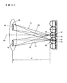
図10は、マイクロレンズを用いた瞳分割型位相差検出方式の焦点検出光学系の構成を示す。図において、90は、交換レンズ202(図1参照)の予定結像面に配置されたマイクロレンズの前方dの距離に設定された射出瞳である。距離dは、マイクロレンズの曲率、屈折率、マイクロレンズと光電変換部との間の距離などに応じて決まる距離であって、この明細書では“測距瞳距離”という。91は交換レンズ202の光軸、50、60はマイクロレンズ、(52,53)、(62,63)はマイクロレンズ50,60に対応する光電変換部、72,73、82,83は焦点検出用の光束である。
FIG. 10 shows a configuration of a pupil division type phase difference detection type focus detection optical system using a microlens. In the figure,
また、92はマイクロレンズ50,60により射出瞳90に投影された光電変換部52、62の領域であり、この明細書では“測距瞳”という。93はマイクロレンズ50,60により射出瞳90に投影された光電変換部53,63の領域、すなわち測距瞳である。なお、図10ではわかりやすくするために測距瞳92,93を楕円形の領域で示すが、実際は光電変換部52、53、62、63の形状が拡大投影された形状となる。
図10では、光軸91上にある焦点検出用画素(マイクロレンズ50と1対の光電変換部52,53からなる)と、隣接する焦点検出用画素(マイクロレンズ60と1対の光電変換部62,63からなる)を模式的に例示しているが、その他の焦点検出用画素においても、1対の光電変換部はそれぞれ1対の測距瞳92,93から各マイクロレンズに到来する光束を受光する。焦点検出用画素の配列方向は、1対の測距瞳の並び方向、すなわち1対の光電変換部の並び方向と一致させる。
In FIG. 10, focus detection pixels (comprising a
マイクロレンズ50、60は光学系の予定結像面近傍に配置されており、光軸91上に配置されたマイクロレンズ50によってその背後に配置された1対の光電変換部52、53の形状がマイクロレンズ50、60から測距瞳距離dだけ離間した射出瞳90上に投影され、その投影形状は測距瞳92,93を形成する。マイクロレンズ50に隣接して配置されたマイクロレンズ60によってその背後に配置された1対の光電変換部62、63の形状が測距瞳距離dだけ離間した射出瞳90上に投影され、その投影形状は測距瞳92,93を形成する。すなわち、測距瞳距離dにある射出瞳90上で各焦点検出用画素の光電変換部の投影形状(測距瞳92,93)が一致するように、各画素のマイクロレンズと光電変換部の位置関係が決定されている。
The
光電変換部52は、測距瞳92を通過してマイクロレンズ50に向う焦点検出光束72によって、マイクロレンズ50上に形成される像の強度に対応した信号を出力する。光電変換部53は、測距瞳93を通過してマイクロレンズ50に向う焦点検出光束73によって、マイクロレンズ50上に形成される像の強度に対応した信号を出力する。また、光電変換部62は、測距瞳92を通過してマイクロレンズ60に向う焦点検出光束82によって、マイクロレンズ60上に形成される像の強度に対応した信号を出力する。光電変換部63は、測距瞳93を通過してマイクロレンズ60に向う焦点検出光束83によって、マイクロレンズ60上に形成される像の強度に対応した信号を出力する。
The
上述した焦点検出用画素を直線状に多数配置し、各画素の1対の光電変換部の出力を測距瞳92および測距瞳93に対応した出力グループにまとめることによって、測距瞳92と測距瞳93をそれぞれ通過する焦点検出光束が焦点検出用画素列上に形成する1対の像の強度分布に関する情報が得られる。この情報に対して後述する像ズレ検出演算処理(相関演算処理、位相差検出処理)を施すことによって、いわゆる瞳分割方式で1対の像の像ズレ量が検出される。さらに、像ズレ量に所定の変換処理を施すことにより、予定結像面に対する現在の結像面(予定結像面上のマイクロレンズアレイの位置に対応した焦点検出位置における結像面)の偏差(デフォーカス量)が算出される。
A large number of focus detection pixels described above are arranged in a straight line, and the output of a pair of photoelectric conversion units of each pixel is grouped into an output group corresponding to the
ここで、瞳分割型位相差検出方式を用いた焦点検出装置において、焦点検出用画素の1対の光電変換部で1対の像を検出する場合に、光電変換部の間に出力の漏れこみ(クロストーク)が発生して像ズレ量の検出精度が悪化する問題について説明する。 Here, in the focus detection apparatus using the pupil division type phase difference detection method, when a pair of images is detected by the pair of photoelectric conversion units of the focus detection pixels, an output leaks between the photoelectric conversion units. A problem that the detection accuracy of the image shift amount deteriorates due to occurrence of (crosstalk) will be described.
このような瞳分割型位相差検出方式を用いた焦点検出装置において、像ズレ量をδとした場合に1対の像に対応する1対の像関数をF(x)、F(x+δ)とすると、一方の像関数F(x)に対し他方の像関数F(x+δ)をx方向に相対的に変位させ、ふたつの像関数が一致したときの変位量から像ズレ量δを決定する。ここで、xは焦点検出用画素の配列方向の位置を示す。この一実施の形態では、一方の光電変換部から他方の光電変換部へ漏れこむ出力(クロストーク)を、一方の光電変換部の出力で除した比率をクロストーク率と定める。 In such a focus detection apparatus using the pupil division type phase difference detection method, when an image shift amount is δ, a pair of image functions corresponding to a pair of images are F (x) and F (x + δ). Then, the other image function F (x + δ) is displaced relative to the one image function F (x) in the x direction, and the image displacement amount δ is determined from the displacement amount when the two image functions match. Here, x indicates the position of the focus detection pixels in the arrangement direction. In this embodiment, the ratio obtained by dividing the output (crosstalk) leaking from one photoelectric conversion unit to the other photoelectric conversion unit by the output of one photoelectric conversion unit is defined as the crosstalk rate.
一方の光電変換部からのクロストーク率をαとすると、一方の光電変換部で検出される像関数G(x)はクロストークがない場合の像関数F(x)と対となる光電変換部で検出される像関数F(x+δ)にクロストーク率αを乗じたものの和となり、一方の光電変換部で検出される像関数H(x)はクロストークがない場合の像関数F(x+δ)と対となる光電変換部で検出される像関数F(x)にクロストーク率αを乗じたものの和となる。
G(x)=F(x)+α・F(x+δ)、
H(x)=F(x+δ)+α・F(x) ・・・(1)
このような1対の像関数G(x)とH(x)を用いて像ズレ検出を行うと、検出された像ズレ量は真の像ズレ量δよりも小さな量となってしまう。
When the crosstalk rate from one photoelectric conversion unit is α, the image function G (x) detected by one photoelectric conversion unit is paired with the image function F (x) when there is no crosstalk. Is the sum of the image function F (x + δ) detected in
G (x) = F (x) + α · F (x + δ),
H (x) = F (x + δ) + α · F (x) (1)
When image shift detection is performed using such a pair of image functions G (x) and H (x), the detected image shift amount is smaller than the true image shift amount δ.
このようなクロストークが発生する原因は、(1)光電変換部を形成する半導体基板内部において、入射光により光電変換部の端部や深部で発生した電子が周辺の光電変換部に拡散する。(2)半導体表面に形成される遮光メタル層、配線メタル層の間を光が反射伝播する。(3)焦点検出用画素へ入射した光の一部が焦点検出用画素外へ反射され、この反射光がセンサーパッケージ上のカバーガラスなどで再反射されて周辺の撮像用画素に入射する、などが考えられる。 The causes of the occurrence of such crosstalk are as follows: (1) Inside the semiconductor substrate forming the photoelectric conversion part, electrons generated at the end and deep part of the photoelectric conversion part by the incident light diffuse to the peripheral photoelectric conversion part. (2) Light is reflected and propagated between the light shielding metal layer and the wiring metal layer formed on the semiconductor surface. (3) A part of the light incident on the focus detection pixel is reflected outside the focus detection pixel, and the reflected light is re-reflected by a cover glass or the like on the sensor package and incident on the surrounding imaging pixels. Can be considered.
さらに、クロストークについて詳細に説明する。図11は、焦点検出用画素においてクロストークが発生する原因を説明するための図であり、焦点検出用画素の断面構造を示す。図11において、焦点検出用画素はマイクロレンズ、フィルタ、遮光メタル、配線メタル、半導体基板上に形成されたフォトダイオードからなる。なお、焦点検出用画素にはフィルターを備えなくてもよい。 Further, crosstalk will be described in detail. FIG. 11 is a diagram for explaining the cause of the occurrence of crosstalk in the focus detection pixel, and shows a cross-sectional structure of the focus detection pixel. In FIG. 11, the focus detection pixel includes a microlens, a filter, a light shielding metal, a wiring metal, and a photodiode formed on a semiconductor substrate. Note that the focus detection pixel may not include a filter.
このような構成において、クロストークの発生原因(1)は、光電変換部(フォトダイオード)に入射した光がフォトダイオードの外部や深部で光電変換されて電子を発生した後、この電子が拡散して隣接する同じ焦点検出用画素の異なる光電変換部や周囲の焦点検出用画素の光電変換部に混ざり込むことによる。クロストークの発生原因(2)は、焦点検出用画素に入射した光が遮光メタルと配線メタルの隙間を反射伝播して、隣接する同じ焦点検出用画素の異なる光電変換部や周囲の焦点検出用画素の光電変換部に混ざり込むことによる。クロストークの発生原因(3)は、焦点検出用画素に入射した光がフォトダイオードなどで反射していったん焦点検出用画素外に出射した後、センサーパッケージのカバーガラスや、オプチカルローパスフィルターや、赤外カットフィルターなどで反射され、再び同じ焦点検出用画素の異なる光電変換部や周囲の焦点検出用画素の光電変換部に入射して混ざり込むことによる。 In such a configuration, the cause (1) of the occurrence of crosstalk is that light incident on the photoelectric conversion unit (photodiode) is photoelectrically converted outside or at a deep part of the photodiode to generate electrons, and then the electrons diffuse. This is because they are mixed in different photoelectric conversion units of the same focus detection pixel adjacent to each other or photoelectric conversion units of surrounding focus detection pixels. The cause (2) of the occurrence of crosstalk is that the light incident on the focus detection pixel is reflected and propagated through the gap between the light shielding metal and the wiring metal, so that different photoelectric conversion units of the same focus detection pixel adjacent to each other and the surrounding focus detection By mixing with the photoelectric conversion part of the pixel. The cause of the occurrence of crosstalk (3) is that light incident on the focus detection pixel is reflected by a photodiode and emitted to the outside of the focus detection pixel, and then the sensor package cover glass, optical low-pass filter, red This is because the light is reflected by an outer cut filter or the like, and again enters and mixes with a different photoelectric conversion unit of the same focus detection pixel or a surrounding photoelectric conversion unit of the focus detection pixel.
クロストークの発生原因(1)〜(3)はともに入射光線の角度特性によりクロストークの影響度が変化し、入射光線がマイクロレンズの光軸となす角度が大きくなるにつれてクロストークが増加する傾向にある。基本的には、焦点検出用画素の光電変換部へは測距瞳(例えば図10に示す92,93)を通過した光線が入射するが、クロストークを発生する光線は測距瞳以外の領域からも焦点検出用画素に入射する。 The causes (1) to (3) of the occurrence of crosstalk all change the degree of influence of the crosstalk due to the angle characteristics of the incident light, and the crosstalk tends to increase as the angle formed by the incident light and the optical axis of the microlens increases. It is in. Basically, a light beam that has passed through a distance measuring pupil (for example, 92 and 93 shown in FIG. 10) enters the photoelectric conversion unit of the focus detection pixel, but a light beam that generates crosstalk is an area other than the distance measuring pupil. Also enters the focus detection pixels.
一般に、撮影レンズの絞り開口の周辺部を通る光線の焦点検出用画素への入射角度は、絞り開口の中心部を通る光線の焦点検出用画素への入射角度より大きくなり、クロストークにより大きく影響する。このようにクロストーク量は撮影レンズの絞り開口F値に応じて変化するので、クロストーク補正に用いるクロストーク率を撮影レンズの絞り開口F値に応じて測定し、絞り開口F値に応じたデータとして記憶しておき、クロストーク補正の際には焦点検出用画素から焦点検出用信号データを取得した時点の絞り開口F値データをレンズ駆動制御装置206(図1参照)から受信し、この絞り開口F値データに応じたクロストーク率を用いて焦点検出用画素から出力される焦点検出用信号データに対しクロストーク補正を行う。 In general, the incident angle of the light beam passing through the periphery of the aperture stop of the photographing lens to the focus detection pixel is larger than the incident angle of the light beam passing through the center of the aperture opening to the focus detection pixel, and is greatly affected by crosstalk. To do. Since the amount of crosstalk changes in accordance with the aperture F value of the photographing lens in this way, the crosstalk ratio used for crosstalk correction is measured in accordance with the aperture opening F value of the photographing lens, and the amount of crosstalk depends on the aperture aperture F value. This is stored as data, and at the time of crosstalk correction, aperture aperture F value data at the time when focus detection signal data is acquired from the focus detection pixel is received from the lens drive control device 206 (see FIG. 1). Crosstalk correction is performed on the focus detection signal data output from the focus detection pixels using a crosstalk rate corresponding to the aperture opening F value data.
また、クロストークの発生原因(1)に関しては、半導体基板への侵入深さが深い長波長光(赤)のほうが影響度は大きくなる。このような光波長によるクロストーク率の変動を入射光の分光分布特性に応じて補正するために、クロストーク率の分光特性を予め測定して記憶しておくとともに、焦点検出用画素の周囲の撮像用画素のRGB出力に基づいて、焦点検出用信号データを取得した時点の焦点検出用画素への入射光線の分光分布特性を求め、クロストークを与える画素の分光分布(フィルタ波長特性)と、測定された入射光の分光分布特性と、記憶されているクロストーク率の分光特性とに基づいて、クロストーク補正に用いるクロストーク率を補正するようにしてもよい。 Further, as for the cause (1) of the occurrence of crosstalk, the influence is larger in the case of long wavelength light (red) having a deep penetration depth into the semiconductor substrate. In order to correct such fluctuations in the crosstalk ratio due to the light wavelength in accordance with the spectral distribution characteristics of the incident light, the spectral characteristics of the crosstalk ratio are measured and stored in advance, and around the focus detection pixels. Based on the RGB output of the imaging pixel, the spectral distribution characteristic of the incident light beam to the focus detection pixel at the time of acquiring the focus detection signal data is obtained, and the spectral distribution (filter wavelength characteristic) of the pixel giving crosstalk, The crosstalk ratio used for crosstalk correction may be corrected based on the measured spectral distribution characteristic of the incident light and the stored spectral characteristic of the crosstalk ratio.
クロストークの発生原因(3)に関しては、クロストーク原因となる光線がクロストークを与える画素のフィルターとクロストークを受ける画素のフィルターとを通過することになるので、クロストークの原因となる光の波長に応じてクロストーク率が変動する。このようなクロストーク率の変動を入射光の分光分布特性に応じて補正するために、クロストークを与える画素の分光分布(フィルター波長特性)と、クロストークを受ける画素の分光分布(フィルター波長特性)の組み合わせに対しクロストーク率の分光特性を予め測定して記憶しておくとともに、焦点検出用画素の周囲の撮像用画素のRGB出力に基づき焦点検出用信号データを取得した時点の焦点検出用画素への入射光線の分光分布特性を求め、クロストークを与える画素の分光分布(フィルタ波長特性)と、クロストークを受ける画素の分光分布(フィルタ波長特性)と、測定された入射光の分光分布特性と、記憶されたクロストーク率の分光特性に基づいて、クロストーク補正に用いるクロストーク率を補正するようにしてもよい。 Regarding the cause of the occurrence of crosstalk (3), the light beam causing the crosstalk passes through the filter of the pixel that gives the crosstalk and the filter of the pixel that receives the crosstalk. The crosstalk rate varies depending on the wavelength. In order to correct such fluctuations in the crosstalk rate according to the spectral distribution characteristics of the incident light, the spectral distribution (filter wavelength characteristics) of the pixels giving the crosstalk and the spectral distribution (filter wavelength characteristics) of the pixels receiving the crosstalk ) For the focus detection at the time when the focus detection signal data is acquired based on the RGB output of the imaging pixels around the focus detection pixels. Obtain the spectral distribution characteristics of the incident light to the pixel, and the spectral distribution (filter wavelength characteristics) of the pixel that gives crosstalk, the spectral distribution of the pixels that receive crosstalk (filter wavelength characteristics), and the measured spectral distribution of incident light The crosstalk rate used for crosstalk correction may be corrected based on the characteristics and the spectral characteristics of the stored crosstalk rate.
図12は、一実施の形態のデジタルスチルカメラ(撮像装置)の撮像動作を示すフローチャートである。ボディ駆動制御装置214は、ステップ100でカメラの電源スイッチ(不図示)がオンされるとこの動作を開始する。続くステップ110で撮像用画素の画像データを間引き読み出しし、電子ビューファインダーに表示する。ステップ120では焦点検出用画素列から1対の像に対応した1対の像データを読み出す。ここでは、ユーザーが焦点検出エリア選択スイッチ(不図示)を操作していずれかの焦点検出エリアを選択しているものとする。
FIG. 12 is a flowchart illustrating an imaging operation of the digital still camera (imaging device) according to the embodiment. The body
ステップ130において、焦点検出用画素列から読み出された1対の像データに対しクロストーク補正処理を施す。このクロストーク補正処理については後述する。ステップ140において、クロストーク補正処理がなされた1対の像データに基づいて像ズレ検出演算処理(相関演算処理)を行い、像ズレ量を演算し、さらに像ズレ量をデフォーカス量に変換する。なお、相関演算処理については詳細を後述する。 In step 130, crosstalk correction processing is performed on the pair of image data read from the focus detection pixel array. This crosstalk correction process will be described later. In step 140, an image shift detection calculation process (correlation calculation process) is performed based on the pair of image data subjected to the crosstalk correction process, an image shift amount is calculated, and the image shift amount is further converted into a defocus amount. . Details of the correlation calculation process will be described later.
ステップ150において合焦近傍か否か、つまり算出されたデフォーカス量の絶対値が所定値以内であるか否かを調べる。合焦近傍でないと判定した場合はステップ160へ進み、デフォーカス量をレンズ駆動制御装置206に送信し、交換レンズ202のフォーカシングレンズ208を合焦位置に駆動させ、ステップ110へ戻って上述した動作を繰り返す。なお、焦点検出不能な場合もこのステップに分岐し、レンズ駆動制御装置206にスキャン駆動命令を送信し、交換レンズ202のフォーカシングレンズ208を無限から至近までの間でスキャン駆動させ、ステップ110へ戻って上述した動作を繰り返す。
In step 150, it is checked whether or not the focus is close, that is, whether or not the calculated absolute value of the defocus amount is within a predetermined value. If it is determined that the lens is not in focus, the process proceeds to step 160, the defocus amount is transmitted to the lens
一方、合焦近傍であると判定した場合はステップ170へ進み、シャッターボタン(不図示)によりシャッターレリーズ操作がなされたか否かを判定し、なされていないと判定した場合はステップ110へ戻って上述した動作を繰り返す。シャッターレリーズ操作がなされたと判定した場合はステップ180へ進み、レンズ駆動制御装置206に対して絞り調整命令を送信し、交換レンズ202の絞り値を制御F値(ユーザーまたは自動により設定されたF値)にする。絞り制御が終了した時点で、撮像素子212に撮像動作を行わせ、撮像素子212のすべての撮像用画素の画像データとすべての焦点検出用画素の焦点検出用信号データを読み出す。
On the other hand, if it is determined that it is close to the in-focus state, the process proceeds to step 170, where it is determined whether or not a shutter release operation has been performed by a shutter button (not shown), and if it is determined that the shutter release operation has not been performed, the process returns to step 110 and described above. Repeat the operation. If it is determined that the shutter release operation has been performed, the process proceeds to step 180, where an aperture adjustment command is transmitted to the lens
ステップ190において、焦点検出用画素位置の画像データを、焦点検出用画素の焦点検出用信号データおよび周囲の撮像用画素の画像データに基づいて補間する。ステップ200では、撮像用画素の画像データおよび補間された画像データからなる画像データをメモリーカード219に保存し、ステップ110へ戻って上述した動作を繰り返す。
In step 190, the image data at the focus detection pixel position is interpolated based on the focus detection signal data of the focus detection pixel and the image data of the surrounding imaging pixels. In step 200, the image data including the image data of the imaging pixels and the interpolated image data is stored in the
次に、図12のステップ130におけるクロストーク補正処理について説明する。図13は焦点検出用画素311におけるクロストークの説明図である。図において、焦点検出用画素311の1対の光電変換部(12,13)から出力される焦点検出用信号データをA2(h,v)、A1(h,v)とする。ここで、h、vは図3に示す2次元画素配置における水平方向および垂直方向の画素の位置を示すための変数であり、例えばA2(h,v)、A1(h,v)はh列目、v行目にある焦点検出用画素の1対の焦点検出用信号データを示している。
Next, the crosstalk correction process in step 130 of FIG. 12 will be described. FIG. 13 is an explanatory diagram of crosstalk in the
図13において、光電変換部12から光電変換部13へのクロストーク率をβ、光電変換部13から光電変換部12へのクロストーク率をαとする。クロストーク率は1対の光電変換部の一方を遮光した試作センサーを用いて測定したり、測距瞳上で一方の光電変換部が受光する光束を遮光して測定され、ボディ駆動制御装置214(図1参照)に記憶される。クロストークがない場合の1対の光電変換部から出力される焦点検出用信号データをB2(h,v)、B1(h,v)とすると、クロストークの影響を受けた焦点検出用信号データA2(h,v)、A1(h,v)は以下のようになる。
A1(h,v)=B1(h,v)+β・B2(h,v)、
A2(h,v)=B2(h,v)+α・B1(h,v) ・・・(2)
In FIG. 13, the crosstalk rate from the
A1 (h, v) = B1 (h, v) + β · B2 (h, v),
A2 (h, v) = B2 (h, v) + α · B1 (h, v) (2)
クロストークの影響は本来の出力に対して僅かであるとして、B2(h,v)≒A2(h,v)、B1(h,v)≒A1(h,v)を(2)式に代入すれば、クロストークの影響を除去して補正した焦点検出用信号データB2(h,v)、B1(h,v)は以下のように求められる。
B1(h,v)=A1(h,v)−β・A2(h,v)、
B2(h,v)=A2(h,v)−α・A1(h,v) ・・・(3)
(3)式の右辺は光電変換部から出力される焦点検出用信号データおよび予め定められたクロストーク率であるから、(3)式により補正焦点検出用信号データを演算で求めることができる。
Substituting B2 (h, v) ≈A2 (h, v) and B1 (h, v) ≈A1 (h, v) into the equation (2), assuming that the influence of crosstalk is slight with respect to the original output. Then, the focus detection signal data B2 (h, v) and B1 (h, v) corrected by removing the influence of the crosstalk can be obtained as follows.
B1 (h, v) = A1 (h, v) −β · A2 (h, v),
B2 (h, v) = A2 (h, v) −α · A1 (h, v) (3)
Since the right side of the equation (3) is the focus detection signal data output from the photoelectric conversion unit and the predetermined crosstalk rate, the corrected focus detection signal data can be obtained by calculation according to the equation (3).
クロストークの影響は後述するように、焦点検出用画素に対する入射光線の入射角度や、1対の光電変換部の並び方向に対する入射光線の入射方向にも依存するため、クロストーク率は焦点検出用画素の位置(画面中心からの距離)の関数として定められるとともに、1対の光電変換部に対する1対のクロストーク率は別々に定められている。(3)式をすべての1対の焦点検出用信号データに対して施すことによって、クロストーク補正処理がなされる。 As will be described later, the influence of the crosstalk depends on the incident angle of the incident light with respect to the focus detection pixel and the incident direction of the incident light with respect to the arrangement direction of the pair of photoelectric conversion units. It is determined as a function of the position of the pixel (distance from the center of the screen), and a pair of crosstalk rates for a pair of photoelectric conversion units are separately determined. By applying equation (3) to all pairs of focus detection signal data, crosstalk correction processing is performed.
次に、図12のステップ140における像ズレ検出演算処理(相関演算処理)について説明する。焦点検出用画素が検出する1対の像は、測距瞳がレンズの絞り開口によりけられて光量バランスが崩れている可能性があるので、光量バランスに対して像ズレ検出精度を維持できるタイプの相関演算を施す。クロストーク補正処理が終了した1対のデータ列(B11〜B1M、B21〜B2M:Mはデータ数)に対し、(4)式を用いて相関演算を行い、相関量C(k)を演算する。
C(k)=Σ|B1n・B2n+1+k−B2n+k・B1n+1| ・・・(4)
(4)式において、Σ演算はnについて累積され、nのとる範囲は像ずらし量kに応じてB1n、B1n+1、B2n+k、B2n+1+kのデータが存在する範囲に限定される。像ずらし量kは整数であり、データ列のデータ間隔を単位とした相対的シフト量である。
Next, the image shift detection calculation process (correlation calculation process) in step 140 of FIG. 12 will be described. The pair of images detected by the focus detection pixels is a type that can maintain the image shift detection accuracy with respect to the light amount balance because the distance measurement pupil is displaced by the aperture of the lens and the light amount balance may be lost. The correlation calculation is performed. A correlation calculation is performed on the pair of data strings (B11 to B1M, B21 to B2M: M is the number of data) for which the crosstalk correction processing has been completed, using equation (4), and a correlation amount C (k) is calculated. .
C (k) = Σ | B1n · B2n + 1 + k−B2n + k · B1n + 1 | (4)
In equation (4), the Σ operation is accumulated for n, and the range taken by n is limited to the range in which B1n, B1n + 1, B2n + k, and B2n + 1 + k data exist according to the image shift amount k. The The image shift amount k is an integer and is a relative shift amount with the data interval of the data string as a unit.
(4)式の演算結果は、図14(a)に示すように、1対のデータの相関が高いシフト量(図14(a)ではk=kj=2)において相関量C(k)が極小(小さいほど相関度が高い)になる。(5)式〜(8)式による3点内挿の手法を用いて連続的な相関量に対する極小値C(x)を与えるシフト量xを求める。
x=kj+D/SLOP ・・・(5)、
C(x)= C(kj)−|D| ・・・(6)、
D={C(kj−1)−C(kj+1)}/2 ・・・(7)、
SLOP=MAX{C(kj+1)−C(kj),C(kj−1)−C(kj)} ・・・(8)
As shown in FIG. 14 (a), the calculation result of the equation (4) shows that the correlation amount C (k) is the amount of shift with a high correlation between a pair of data (k = kj = 2 in FIG. 14 (a)). Minimal (the smaller the value, the higher the degree of correlation). The shift amount x that gives the minimum value C (x) with respect to the continuous correlation amount is obtained using the three-point interpolation method according to the equations (5) to (8).
x = kj + D / SLOP (5),
C (x) = C (kj) − | D | (6),
D = {C (kj-1) -C (kj + 1)} / 2 (7),
SLOP = MAX {C (kj + 1) -C (kj), C (kj-1) -C (kj)} (8)
(5)式で算出されたずらし量xの信頼性があるかどうかは、次のようにして判定する。図14(b)に示すように、1対のデータの相関度が低い場合は、内挿された相関量の極小値C(x)の値が大きくなる。したがって、C(x)が所定のしきい値以上の場合は算出されたずらし量の信頼性が低いと判定し、算出されたずらし量xをキャンセルする。あるいは、C(x)をデータのコントラストで規格化するために、コントラストに比例した値となるSLOPでC(x)を除した値が所定値以上の場合は、算出されたずらし量の信頼性が低いと判定し、算出されたずらし量xをキャンセルする。あるいはまた、コントラストに比例した値となるSLOPが所定値以下の場合は、被写体が低コントラストであり、算出されたずらし量の信頼性が低いと判定し、算出されたずらし量xをキャンセルする。 Whether or not the shift amount x calculated by the equation (5) is reliable is determined as follows. As shown in FIG. 14B, when the degree of correlation between a pair of data is low, the value of the minimal value C (x) of the interpolated correlation amount increases. Therefore, when C (x) is equal to or greater than a predetermined threshold value, it is determined that the calculated shift amount has low reliability, and the calculated shift amount x is canceled. Alternatively, in order to normalize C (x) with the contrast of data, when the value obtained by dividing C (x) by SLOP that is proportional to the contrast is equal to or greater than a predetermined value, the reliability of the calculated shift amount Is determined to be low, and the calculated shift amount x is canceled. Alternatively, when SLOP that is a value proportional to the contrast is equal to or less than a predetermined value, it is determined that the subject has low contrast and the reliability of the calculated shift amount is low, and the calculated shift amount x is canceled.
図14(c)に示すように、1対のデータの相関度が低く、シフト範囲kmin〜kmaxの間で相関量C(x)の落ち込みがない場合は、極小値C(x)を求めることができず、このような場合は焦点検出不能と判定する。 As shown in FIG. 14C, when the degree of correlation of a pair of data is low and there is no drop in the correlation amount C (x) between the shift ranges kmin to kmax, the minimum value C (x) is obtained. In such a case, it is determined that the focus cannot be detected.
なお、相関演算式としては(4)式に限定されず、測距瞳がレンズの絞り開口によりけられて光量バランスが崩れても像ズレ検出精度を維持できるタイプの相関演算式であればよい。算出されたずらし量xの信頼性があると判定された場合は、(9)式により像ズレ量shftに換算する。
shft=PY・x ・・・(9)
(9)式において、PYは検出ピッチ(焦点検出画素のピッチ)である。(9)式で算出された像ズレ量shftに所定の変換係数kを乗じてデフォーカス量defへ変換する。
def=k・shft ・・・(10)
The correlation calculation formula is not limited to the formula (4), and any correlation calculation formula may be used as long as the distance measurement pupil is displaced by the aperture of the lens and the light quantity balance is lost, so that the image shift detection accuracy can be maintained. . If it is determined that the calculated shift amount x is reliable, it is converted into the image shift amount shft by the equation (9).
shft = PY · x (9)
In the equation (9), PY is a detection pitch (a pitch of focus detection pixels). The image shift amount shft calculated by the equation (9) is multiplied by a predetermined conversion coefficient k to be converted into a defocus amount def.
def = k · shft (10)
《一実施の形態の変形例》
図3に示す撮像素子212では、焦点検出用画素311を撮像用画素配列の1行に配列した例を示したが、図15に示すように焦点検出用画素311を複数行連続して配列してもよい。
<< Modification of Embodiment >>
In the
図16、図17は、図15に示す焦点検出用画素配列におけるクロストークの説明図である。h列目、v行目の焦点検出用画素の1対の光電変換部から出力される焦点検出用信号データをA1(h,v)、A2(h,v)とする。図16に、クロストークの影響を受けた光電変換部の位置とその光電変換部の焦点検出用信号データA1(h,v)、クロストークの影響を与えた光電変換部の位置とその光電変換部の焦点検出用信号データ、およびクロストーク率βi(i=0〜7)を示す。また、図17には、クロストークの影響を受けた光電変換部の位置とその光電変換部の焦点検出用信号データA2(h,v)、クロストークの影響を与えた光電変換部の位置とその光電変換部の焦点検出用信号データ、およびクロストーク率αi(i=0〜7)を示す。 16 and 17 are explanatory diagrams of crosstalk in the focus detection pixel array shown in FIG. The focus detection signal data output from the pair of photoelectric conversion units of the focus detection pixels in the h-th column and the v-th row are denoted by A1 (h, v) and A2 (h, v). FIG. 16 shows the position of the photoelectric conversion unit affected by the crosstalk, focus detection signal data A1 (h, v) of the photoelectric conversion unit, the position of the photoelectric conversion unit affected by the crosstalk, and the photoelectric conversion thereof. The focus detection signal data and the crosstalk rate βi (i = 0 to 7) are shown. FIG. 17 shows the position of the photoelectric conversion unit affected by the crosstalk, the focus detection signal data A2 (h, v) of the photoelectric conversion unit, and the position of the photoelectric conversion unit affected by the crosstalk. The focus detection signal data and the crosstalk rate αi (i = 0 to 7) of the photoelectric conversion unit are shown.
クロストークがない場合の光電変換部の焦点検出用データをB1(h+m,v+n)、B2(h+m,v+n)とすると、クロストークの影響を受けた出力データA1(h,v)、A2(h,v)は以下のようになる。
A1(h,v)=B1(h,v)+β0・B2(h,v)+β1・B2(h,v+1)+β2・B1(h,v+1)+β3・B2(h−1,v+1)+β4・B2(h−1,v)+β5・B2(h−1,v−1)+β6・B1(h,v−1)+β7・B2(h,v−1)、
A2(h,v)=B2(h,v)+α0・B1(h,v)+α1・B1(h,v+1)+α2・B2(h,v+1)+α3・B1(h+1,v+1)+α4・B1(h+1,v)+α5・B1(h+1,v−1)+α6・B2(h,v−1)+α7・B1(h,v−1) ・・・(11)
If the focus detection data of the photoelectric conversion unit when there is no crosstalk is B1 (h + m, v + n) and B2 (h + m, v + n), the output data A1 (h, v) and A2 (h , v) is as follows.
A1 (h, v) = B1 (h, v) + β0 · B2 (h, v) + β1 · B2 (h, v + 1) + β2 · B1 (h, v + 1) + β3 · B2 (h-1, v + 1) + β4 B2 (h-1, v) + β5B2 (h-1, v-1) + β6B1 (h, v-1) + β7B2 (h, v-1)
A2 (h, v) = B2 (h, v) + α0 · B1 (h, v) + α1 · B1 (h, v + 1) + α2 · B2 (h, v + 1) + α3 · B1 (h + 1, v + 1) + α4 · B1 (h + 1, v) + α5 · B1 (h + 1, v−1) + α6 · B2 (h, v−1) + α7 · B1 (h, v−1) (11)
クロストークの影響は本来の出力に対して僅かであるとして、B1(h+m,v+n)≒A1(h+m,v+n)、B2(h+m,v+n)≒A2(h+m,v+n)を(11)式に代入すると、クロストークの影響を除去して補正した焦点検出用信号データB1(h,v)、B2(h,v)の算出式は以下のようになる。
B1(h,v)=A1(h,v)−β0・A2(h,v)−β1・A2(h,v+1)−β2・A1(h,v+1)−β3・A2(h−1,v+1)−β4・A2(h−1,v)−β5・A2(h−1,v−1)−β6・A1(h,v−1)−β7・A2(h,v−1)、
B2(h,v)=A2(h,v)−α0・A1(h,v)−α1・A1(h,v+1)−α2・A2(h,v+1)−α3・A1(h+1,v+1)−α4・A1(h+1,v)−α5・A1(h+1,v−1)−α6・A2(h,v−1)−α7・A1(h,v−1) ・・・(12)
Assuming that the influence of crosstalk is slight with respect to the original output, B1 (h + m, v + n) ≈A1 (h + m, v + n) and B2 (h + m, v + n) ≈A2 (h + m, v + n) are substituted into equation (11). Then, the calculation formulas of the focus detection signal data B1 (h, v) and B2 (h, v) corrected by removing the influence of the crosstalk are as follows.
B1 (h, v) = A1 (h, v) −β0 · A2 (h, v) −β1 · A2 (h, v + 1) −β2 · A1 (h, v + 1) −β3 · A2 (h−1 , v + 1) -β4 · A2 (h-1, v) -β5 · A2 (h-1, v-1) -β6 · A1 (h, v-1) -β7 · A2 (h, v-1),
B2 (h, v) = A2 (h, v) −α0 · A1 (h, v) −α1 · A1 (h, v + 1) −α2 · A2 (h, v + 1) −α3 · A1 (h + 1, v + 1) -Α4 · A1 (h + 1, v) -α5 · A1 (h + 1, v-1) -α6 · A2 (h, v-1) -α7 · A1 (h, v-1) (12)
クロストーク量は光電変換部間の距離に応じて変化し、上記クロストーク補正において光電変換部間の距離が大きくなるほどクロストーク率も一般的には小さくなる。例えば図15において、β3<β4となる。 The amount of crosstalk changes according to the distance between the photoelectric conversion units, and the crosstalk rate generally decreases as the distance between the photoelectric conversion units increases in the crosstalk correction. For example, in FIG. 15, β3 <β4.
図15に示す焦点検出画素配列においては、同じサイズの光電変換部を有する焦点検出画素を配列しているが、異なるサイズ光電変換部を有する焦点検出画素を配列してもよい。図18は1行おきにサイズの異なる光電変換部を備えた焦点検出用画素を配列した場合のクロストークの説明図であり、図16に示す画素配列のクロストークに対応する。v行目には図16と同じサイズの光電変換部を備えた焦点検出用画素が配列されている。一方、v−1行目とv+1行目にはv行目の焦点検出用画素の光電変換部のサイズより小さいサイズの光電変換部を備えた焦点検出用画素が配列されている。h列目、v行目の焦点検出用画素の1対の光電変換部から出力される焦点検出用信号データをA1(h,v)、A2(h,v)とする。 In the focus detection pixel array shown in FIG. 15, focus detection pixels having photoelectric conversion units of the same size are arrayed, but focus detection pixels having different size photoelectric conversion units may be arrayed. FIG. 18 is an explanatory diagram of crosstalk in the case where focus detection pixels having photoelectric conversion units having different sizes every other row are arranged, and corresponds to the crosstalk of the pixel arrangement shown in FIG. In the v-th row, focus detection pixels each having a photoelectric conversion unit having the same size as that in FIG. 16 are arranged. On the other hand, focus detection pixels having photoelectric conversion units smaller in size than the photoelectric conversion units of the focus detection pixels in the vth row are arranged in the (v−1) th and v + 1th rows. The focus detection signal data output from the pair of photoelectric conversion units of the focus detection pixels in the h-th column and the v-th row are denoted by A1 (h, v) and A2 (h, v).
図18には、クロストークの影響を受けた光電変換部の位置とその光電変換部の焦点検出用信号データA1(h,v)、クロストークの影響を与えた光電変換部の位置とその光電変換部の焦点検出用信号データ、およびクロストーク率をβi、βi’を示す。クロストーク率βiは、h列目、v行目の焦点検出用画素の光電変換部が同じ行の隣接する同じサイズの光電変換部から受けるクロストークの影響を表し、また、クロストーク率βi’は、h列目、v行目の焦点検出用画素の上下の行において周囲に位置する小さいサイズの光電変換部から受けるクロストークの影響を表す。 FIG. 18 shows the position of the photoelectric conversion unit affected by the crosstalk, the focus detection signal data A1 (h, v) of the photoelectric conversion unit, the position of the photoelectric conversion unit affected by the crosstalk, and the photoelectric conversion unit. The focus detection signal data of the conversion unit and the crosstalk rate are represented by βi and βi ′. The crosstalk rate βi represents the influence of crosstalk that the photoelectric conversion units of the focus detection pixels in the h-th column and the v-th row receive from adjacent photoelectric conversion units of the same size, and the crosstalk rate βi ′. Represents the influence of crosstalk received from a small-sized photoelectric conversion unit located in the upper and lower rows of the focus detection pixels in the h-th column and the v-th row.
このような焦点検出用画素配列では、h列目、v行目の焦点検出用画素の光電変換部の補正後の焦点検出用信号データB1(h,v)は次のようになる。
B1(h,v)=A1(h,v)−β0・A2(h,v)−β1'・A2(h,v+1)−β2’・A1(h,v+1)−β3’・A2(h−1,v+1)−β4・A2(h−1,v)−β5’・A2(h−1,v−1)−β6’・A1(h,v−1)−β7’・A2(h,v−1) ・・・(13)
同様に、もう一方の光電変換部の補正後の焦点検出用信号データB2(h,v)も算出することができる。また、同様な考え方で小さいサイズの光電変換部に対する補正後の焦点検出用信号データも算出することができる。
In such a focus detection pixel array, the focus detection signal data B1 (h, v) after correction of the photoelectric conversion units of the focus detection pixels in the h-th column and the v-th row are as follows.
B1 (h, v) = A1 (h, v) −β0 · A2 (h, v) −β1 ′ · A2 (h, v + 1) −β2 ′ · A1 (h, v + 1) −β3 ′ · A2 ( h-1, v + 1)-. beta.4.A2 (h-1, v)-. beta.5'.A2 (h-1, v-1)-. beta.6'.A1 (h, v-1)-. beta.7'.A2 (h , v-1) (13)
Similarly, the focus detection signal data B2 (h, v) after correction of the other photoelectric conversion unit can also be calculated. Further, corrected focus detection signal data for a small size photoelectric conversion unit can be calculated in the same way.
クロストーク量はクロストークを発生する光電変換部のサイズに応じて変化し、上述したクロストーク補正において光電変換部のサイズが小さくなるほどクロストーク率も一般的には小さくなる。例えば図18において、焦点検出用信号データA1(h,v)を発生する光電変換部から焦点検出用信号データA1(h,v+1)を発生する光電変換部へのクロストーク率は、焦点検出用信号データA1(h,v+1)を発生する光電変換部から焦点検出用信号データA1(h,v)を発生する光電変換部へのクロストーク率β2’より小さくなる。 The amount of crosstalk changes according to the size of the photoelectric conversion unit that generates crosstalk, and the crosstalk rate generally decreases as the size of the photoelectric conversion unit decreases in the above-described crosstalk correction. For example, in FIG. 18, the crosstalk ratio from the photoelectric conversion unit that generates focus detection signal data A1 (h, v) to the photoelectric conversion unit that generates focus detection signal data A1 (h, v + 1) is the focus detection The crosstalk rate β2 ′ from the photoelectric conversion unit that generates the signal data A1 (h, v + 1) to the photoelectric conversion unit that generates the focus detection signal data A1 (h, v) is smaller.
図3に示す撮像素子212では、h列目、v行目の焦点検出用画素の1対の光電変換部のクロストーク補正後の焦点検出用信号データB1(h,v)、B2(h,v)を、(3)式に示すように対になる光電変換部から出力される焦点検出用信号データに基づいて求めているが、隣接する焦点検出用画素の光電変換部の焦点検出用信号データと、周囲の撮像用画素の光電変換部から出力される画像データに基づいて求めることもできる。
In the
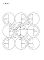
図19はベイヤー配列のGB行(v行)に焦点検出用画素を配列し、上下の行がRGの撮像用画素配列となっている場合のクロストークの説明図であり、図16に示す画素配列に対応する。v行目には、図16と同じサイズの光電変換部を備えた焦点検出用画素が配列されている。また、v−1行目とv+1行目には、v行目の焦点検出用画素の光電変換部のサイズより大きなサイズの光電変換部を備えた撮像用画素(RG)が配列されている。h列目、v行目の焦点検出用画素の1対の光電変換部から出力される焦点検出用信号データをA1(h,v)、A2(h,v)とする。また、v−1行目、v+1行目のRG撮像用画素から出力される画像データをR(h+m,v−1)、G(h+m,v−1)、R(h+m,v+1)、G(h+m,v+1)で表す。 FIG. 19 is an explanatory diagram of crosstalk in the case where focus detection pixels are arranged in GB rows (v rows) of the Bayer array and the upper and lower rows are RG imaging pixel arrays, and the pixels shown in FIG. Corresponds to an array. In the v-th row, focus detection pixels including a photoelectric conversion unit having the same size as that in FIG. 16 are arranged. In the (v-1) th and (v + 1) th rows, imaging pixels (RG) each having a photoelectric conversion unit having a size larger than the size of the photoelectric conversion unit of the focus detection pixel in the vth row are arranged. The focus detection signal data output from the pair of photoelectric conversion units of the focus detection pixels in the h-th column and the v-th row are denoted by A1 (h, v) and A2 (h, v). The image data output from the RG imaging pixels in the (v−1) th and (v + 1) th rows are R (h + m, v−1), G (h + m, v−1), R (h + m, v + 1), G ( h + m, v + 1).
図19には、クロストークの影響を受けた焦点検出用画素の光電変換部の位置とその光電変換部の焦点検出用信号データA1(h,v)、クロストークの影響を与えた焦点検出用画素および撮像用画素の光電変換部の位置とその光電変換部から出力される焦点検出用信号データおよび撮像データ、およびクロストーク率βi、γri、γgiを示す。クロストーク率βiは、h列目、v行目の焦点検出用画素の光電変換部が同じ行の隣接する同じサイズの光電変換部から受けるクロストークの影響を表し、また、クロストーク率γriは、h列目、v行目の焦点検出画素の上下の行において周囲に位置する赤の撮像用画素の光電変換部から受けるクロストークの影響を表し、さらに、クロストーク率γgiは、h列目、v行目の焦点検出用画素の上下の行において周囲に位置する緑の撮像用画素の光電変換部から受けるクロストークの影響を表している。 FIG. 19 shows the position of the photoelectric conversion unit of the focus detection pixel affected by the crosstalk, the focus detection signal data A1 (h, v) of the photoelectric conversion unit, and the focus detection signal affected by the crosstalk. The position of the photoelectric conversion unit of the pixel and the imaging pixel, focus detection signal data and imaging data output from the photoelectric conversion unit, and crosstalk rates βi, γri, and γgi are shown. The crosstalk rate βi represents the influence of the crosstalk that the photoelectric conversion units of the focus detection pixels on the h-th column and the v-th row receive from adjacent photoelectric conversion units of the same size, and the crosstalk rate γri is Represents the influence of crosstalk received from the photoelectric conversion unit of the red imaging pixels located in the upper and lower rows of the focus detection pixels in the h-th and v-th rows, and the crosstalk rate γgi is expressed in the h-th row. , Represents the influence of crosstalk received from the photoelectric conversion unit of the green imaging pixels located in the upper and lower rows of the focus detection pixels in the v-th row.
このような焦点検出用画素配列では、h列目、v行目の焦点検出用画素の光電変換部の補正後の焦点検出用信号データB1(h,v)は次のようになる。
B1(h,v)=A1(h,v)−β0・A2(h,v)−γg1・A2(h+1,v+1)−γr2・R(h,v+1)−γg3・G(h−1,v+1)−β4・A2(h−1,v)−γg5・G(h−1,v−1)−γr6・R(h,v−1)−γg7・G(h+1,v−1) ・・・(14)
同様に、もう一方の光電変換部の補正後の焦点検出用信号データB2(h,v)も算出することができる。
In such a focus detection pixel array, the focus detection signal data B1 (h, v) after correction of the photoelectric conversion units of the focus detection pixels in the h-th column and the v-th row are as follows.
B1 (h, v) = A1 (h, v) −β0 · A2 (h, v) −γg1 · A2 (h + 1, v + 1) −γr2 · R (h, v + 1) −γg3 · G (h−1 , v + 1) -β4 · A2 (h-1, v) -γg5 · G (h-1, v-1) -γr6 · R (h, v-1) -γg7 · G (h + 1, v-1) (14)
Similarly, the focus detection signal data B2 (h, v) after correction of the other photoelectric conversion unit can also be calculated.
クロストーク量は撮像用画素の波長感度に応じて変化し、上述したクロストーク補正においてR画素のクロストーク率はG画素のクロストーク率より一般的には大きくなる。例えば図19において、R画素から出力データA1(h+1,v)を発生する光電変換部へのクロストーク率γr3は、G画素から出力データA1(h,v)を発生する光電変換部へのクロストーク率γg3より大きくなる。 The amount of crosstalk changes according to the wavelength sensitivity of the imaging pixel, and the crosstalk rate of the R pixel is generally larger than the crosstalk rate of the G pixel in the above-described crosstalk correction. For example, in FIG. 19, the crosstalk rate γr3 from the R pixel to the photoelectric conversion unit that generates the output data A1 (h + 1, v) is the crosstalk rate γr3 from the G pixel to the photoelectric conversion unit that generates the output data A1 (h, v). It becomes larger than the talk rate γg3.
図15に示す撮像素子212Aでは、焦点検出用画素311がひとつの画素内に1対の光電変換部を備えた例を示したが、図20に示す撮像素子212Bように、焦点検出用画素313,314が1つの画素内に1つの光電変換部を備えるようにしてもよい。図20において、焦点検出用画素313と焦点検出用画素314が1対になっており、図15に示す焦点検出用画素311に相当する。
In the
焦点検出用画素313は、図21(a)に示すようにマイクロレンズ10と光電変換部16から構成される。また、焦点検出画素314は、図21(b)に示すようにマイクロレンズ10と光電変換部17から構成される。光電変換部16,17はマイクロレンズ10により交換レンズの射出瞳に投影され、図10に示す測距瞳92,93を形成する。したがって、焦点検出用画素313,314の配列によって焦点検出に用いる1対の像の出力を得ることができる。焦点検出用画素内にひとつの光電変換部を備えることによって、撮像素子の信号読み出し回路の構成が複雑になるのを避けることができる。
The
図22は、図21(a)、(b)に示す焦点検出用画素を配列した撮像素子212Bのクロストークの説明図であり、図16に示す画素配列のクロストークに対応する。v行目には図16と同じサイズの光電変換部で図21(a)に示す焦点検出用画素が配列されており、周囲を図21(a)および図21(b)に示す焦点検出用画素に囲まれている。h列目、v行目の焦点検出用画素の光電変換部から出力される焦点検出用信号データをA1(h,v)とする。
FIG. 22 is an explanatory diagram of the crosstalk of the
図22には、クロストークの影響を受けた光電変換部の位置とその光電変換部の焦点検出用信号データA1(h,v)、クロストークの影響を与えた光電変換部の位置とその光電変換部の焦点検出用信号データ、およびクロストーク率ηai、ηbiを示す。クロストーク率ηaiは、h列目、v行目の焦点検出用画素の光電変換部が周囲の図21(a)に示す焦点検出用画素の光電変換部から受けるクロストークの影響を表し、クロストーク率ηbiは、h列目、v行目の焦点検出用画素の光電変換部が周囲の図21(b)に示す焦点検出用画素の光電変換部から受けるクロストークの影響を表している。 FIG. 22 shows the position of the photoelectric conversion unit affected by the crosstalk, the focus detection signal data A1 (h, v) of the photoelectric conversion unit, the position of the photoelectric conversion unit affected by the crosstalk, and the photoelectric conversion unit. The focus detection signal data of the conversion unit and the crosstalk rates ηai and ηbi are shown. The crosstalk rate ηai represents the influence of crosstalk received by the photoelectric conversion units of the focus detection pixels in the h-th column and the v-th row from the photoelectric conversion units of the focus detection pixels shown in FIG. The talk rate ηbi represents the influence of crosstalk received by the photoelectric conversion unit of the focus detection pixel in the h-th column and the v-th row from the photoelectric conversion unit of the focus detection pixel shown in FIG.
このような焦点検出用画素配列では、h列目、v行目の焦点検出用画素の光電変換部の補正後の焦点検出用信号データB1(h,v)は次のようになる。
B1(h,v)=A1(h,v)−ηb0・A2(h+1,v)−ηa1・A1(h+1,v+1)−ηb2・A2(h,v+1)−ηa3・A1(h−1,v+1)−ηb4・A2(h−1,v)−ηa5・A1(h−1,v−1)−ηb6・A2(h,v−1)−ηa7・A1(h+1,v−1) ・・・(15)
同様に、対になる光電変換部の補正後の焦点検出用信号データB2(h+1,v)も算出することができる。
In such a focus detection pixel array, the focus detection signal data B1 (h, v) after correction of the photoelectric conversion units of the focus detection pixels in the h-th column and the v-th row are as follows.
B1 (h, v) = A1 (h, v) −ηb0 · A2 (h + 1, v) −ηa1 · A1 (h + 1, v + 1) −ηb2 · A2 (h, v + 1) −ηa3 · A1 (h−1) , v + 1) −ηb4 · A2 (h−1, v) −ηa5 · A1 (h−1, v−1) −ηb6 · A2 (h, v−1) −ηa7 · A1 (h + 1, v−1) (15)
Similarly, the focus detection signal data B2 (h + 1, v) after correction of the paired photoelectric conversion units can also be calculated.
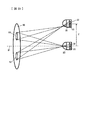
図23は、画面上の焦点検出用画素の位置に応じてクロストークの影響が異なることを説明するための図である。撮影レンズの光軸91上にある1対の光電変換部22,23を備えた焦点検出用画素20と、光軸91から距離Zだけ離れた位置にある1対の光電変換部32,33を備えた焦点検出用画素30を示し、焦点検出用画素20への入射光線の入射角度(光軸となす角度)より焦点検出用画素30への入射光線の入射角度が大きくなっており、周囲の焦点検出用画素や撮像用画素からのクロストーク量は焦点検出用画素30のほうが大きくなる。また、1対の光電変換部間のクロストーク量は、光軸上に位置する焦点検出用画素20の場合は等しくなるが、光軸外に配置された焦点検出用画素30の場合には、光軸に近い光電変換部33から光軸から遠い光電変換部32へのクロストークの量が、光軸から遠い光電変換部32から光軸に近い光電変換部33へのクロストークの量より大きくなる。
FIG. 23 is a diagram for explaining that the influence of crosstalk varies depending on the position of the focus detection pixel on the screen. A
このように、クロストーク量が焦点検出用画素位置に応じて変化する場合には、クロストーク率を光軸からの距離に応じて測定して記憶しておき、クロストーク補正を行う際にクロストーク補正を行う焦点検出用信号データを出力した焦点検出用画素の位置(光軸からの距離)に応じたクロストーク率を用いてクロストーク補正を行うとともに、クロストーク量が光軸に対する光電変換部間の位置関係に応じて変化する場合には、クロストーク率を光電変換部の位置関係に応じて測定して記憶しておき、クロストーク補正を行う際にクロストーク補正に用いる光電変換部の位置関係に応じたクロストーク率を用いてクロストーク補正を行う。 Thus, when the amount of crosstalk changes according to the focus detection pixel position, the crosstalk rate is measured and stored according to the distance from the optical axis, and crosstalk correction is performed when crosstalk correction is performed. Crosstalk correction is performed using the crosstalk rate corresponding to the position (distance from the optical axis) of the focus detection pixel that outputs the focus detection signal data for performing the talk correction, and the crosstalk amount is photoelectrically converted with respect to the optical axis. When changing according to the positional relationship between the units, the crosstalk rate is measured and stored according to the positional relationship of the photoelectric conversion unit, and the photoelectric conversion unit used for the crosstalk correction when performing the crosstalk correction Crosstalk correction is performed using a crosstalk rate corresponding to the positional relationship.
また、上述したように、クロストークを発生する光線は測距瞳以外の領域からも焦点検出用画素に入射する。このような光線は撮影光学系の射出瞳の大きさと射出瞳の距離(光軸上の焦点検出用画素から射出瞳までの距離)によって規定され、光軸外に配置された焦点検出用画素30に対しては、射出瞳大きさと射出瞳の距離に応じてクロストーク率が変化する。このような場合に対応するために、クロストーク補正に用いるクロストーク率を射出瞳の大きさと射出瞳の距離に応じて測定し、射出瞳の大きさおよび射出瞳距離に応じたデータとして記憶しておき、クロストーク補正の際には焦点検出用画素データを取得した時点の射出瞳の大きさデータと射出瞳距離データをレンズ駆動制御装置から受信し、射出瞳の大きさデータと射出瞳距離データに応じたクロストーク率を用いて焦点検出用信号データに対しクロストーク補正を行う。
Further, as described above, the light beam that generates crosstalk enters the focus detection pixel from a region other than the distance measuring pupil. Such a ray is defined by the size of the exit pupil of the photographing optical system and the distance of the exit pupil (distance from the focus detection pixel to the exit pupil on the optical axis), and the
上述したクロストーク補正演算式(12)〜(15)では、クロストーク補正を受ける光電変換部の最近傍にある光電変換部の出力に応じてクロストーク補正を行っているが、補正精度向上のために、クロストーク補正を受ける光電変換部からより遠くの位置にある光線変換部の出力をクロストーク補正に用いるようにすることも可能である。例えば図16においてA1(h,v)を補正するために、A1(h−1,v−1)、A1(h+1,v−1)、A2(h+1,v−1)などを使用することができる。 In the above-described crosstalk correction arithmetic expressions (12) to (15), the crosstalk correction is performed according to the output of the photoelectric conversion unit that is closest to the photoelectric conversion unit that receives the crosstalk correction. For this reason, it is possible to use the output of the light beam conversion unit located farther from the photoelectric conversion unit subjected to crosstalk correction for crosstalk correction. For example, in order to correct A1 (h, v) in FIG. 16, A1 (h-1, v-1), A1 (h + 1, v-1), A2 (h + 1, v-1), etc. may be used. it can.
図3に示す撮像素子212では、撮像用画素がベイヤー配列の色フィルターを備えた例を示したが、色フィルターの構成や配列はこれに限定されることはなく、補色フィルター(緑:G、イエロー:Ye、マゼンタ:Mg,シアン:Cy)の配列を採用してもよい。また、図3に示す撮像素子212では、焦点検出用画素に色フィルターを設けない例を示したが、撮像用画素と同色の色フィルターの内、1つのフィルター、例えば緑フィルターを備えるようにした場合でも、本発明を適用することができる。
In the
図5、図21には焦点検出用画素の光電変換部の形状を円形、半円形にした例を示したが、光電変換部の形状はこれに限定されず、他の形状にしてもよい。例えば焦点検出用画素の光電変換部の形状を楕円や矩形や多角形にすることも可能である。撮像素子の中に形状の異なる光電変換部を備えた焦点検出用画素配列を持つ場合には、それぞれの光電変換部の形状に対応したクロストーク率を測定記憶しておき、クロストーク補正を行う焦点検出用画素の光電変換部形状に応じてクロストーク率を切換えてクロストーク補正を行う。 FIGS. 5 and 21 show examples in which the shape of the photoelectric conversion unit of the focus detection pixel is circular or semicircular, but the shape of the photoelectric conversion unit is not limited to this and may be other shapes. For example, the shape of the photoelectric conversion unit of the focus detection pixel may be an ellipse, a rectangle, or a polygon. When the imaging element has a focus detection pixel array including photoelectric conversion units having different shapes, the crosstalk rate corresponding to the shape of each photoelectric conversion unit is measured and stored, and crosstalk correction is performed. Crosstalk correction is performed by switching the crosstalk rate in accordance with the photoelectric conversion portion shape of the focus detection pixel.
図3に示す撮像素子212では撮像用画素と焦点検出用画素が稠密正方格子配列に配置される例を示したが、稠密六方格子配列に配置してもよい。
In the
本発明はCCDイメージセンサー、CMOSイメージセンサーのどちらに対しても適用することができる。 The present invention can be applied to both a CCD image sensor and a CMOS image sensor.
本発明の撮像装置は、上述したような交換レンズがカメラボディに着脱可能に構成されるデジタルスチルカメラやフィルムスチルカメラに限定されず、レンズ一体型のデジタルスチルカメラ、フィルムスチルカメラ、あるいはビデオカメラにも適用することができる。さらに、携帯電話などに内蔵される小型カメラモジュールや監視カメラやロボットの視覚認識装置などにも適用できる。さらにまた、カメラ以外の焦点検出装置や測距装置、ステレオ測距装置などにも適用できる。 The image pickup apparatus of the present invention is not limited to a digital still camera or a film still camera in which the above-described interchangeable lens is detachably attached to the camera body, but is a lens-integrated digital still camera, film still camera, or video camera. It can also be applied to. Furthermore, the present invention can be applied to a small camera module built in a mobile phone, a surveillance camera, a robot visual recognition device, and the like. Furthermore, the present invention can be applied to a focus detection device other than a camera, a distance measuring device, a stereo distance measuring device, and the like.
11、12、13、16、17;光電変換部、202;交換レンズ、214;ボディ駆動制御装置、212、212A、212B;撮像素子、310;撮像用画素、311、313、314;焦点検出用画素 11, 12, 13, 16, 17; photoelectric conversion unit, 202; interchangeable lens, 214; body drive control device, 212, 212A, 212B; imaging element, 310; imaging pixel, 311, 313, 314; Pixel
Claims (6)
前記第1の光電変換部よりも小さな第2の光電変換部を有する第2の焦点検出用画素が前記第1の焦点検出用画素列の近傍に複数個配列され、前記光学系を通過する第1の対の光束が形成する第2の対の像に対応した第2の対の像信号を生成する第2の焦点検出用画素列と、
前記第1の光電変換部の出力信号と前記第2の光電変換部のサイズに起因するクロストーク率とに基づくクロストーク補正量で当該第2の光電変換部の出力信号を補正すると共に、前記第2の光電変換部の出力信号と前記第1の光電変換部のサイズに起因するクロストーク率とに基づくクロストーク補正量で当該第1の光電変換部の出力信号を補正する補正手段と、
前記補正手段による補正後の前記第1の光電変換部の出力信号により生成される前記第1の対の像信号に基づいて、前記第1の対の像のズレ量を検出すると共に、前記補正手段による補正後の前記第2の光電変換部の出力信号により生成される前記第2の対の像信号に基づいて、前記第2の対の像のズレ量を検出する像ズレ検出手段と、
前記像ズレ検出手段により検出された前記第1の対の像のズレ量または前記第2の対の像のズレ量に基づいて、前記光学系の焦点調節状態を検出する焦点検出手段と、を備え、
前記第1の光電変換部のサイズに起因するクロストーク率は、前記第2の光電変換部のサイズに起因するクロストーク率よりも大きいことを特徴とする焦点検出装置。 A first pair of images corresponding to the first pair of images formed by the first pair of light fluxes passing through the optical system in which a plurality of first focus detection pixels having a first photoelectric conversion unit are arranged. A first focus detection pixel column for generating a signal;
A plurality of second focus detection pixels having a second photoelectric conversion unit smaller than the first photoelectric conversion unit are arranged in the vicinity of the first focus detection pixel row, and pass through the optical system. A second focus detection pixel array that generates a second pair of image signals corresponding to a second pair of images formed by one pair of light beams;
While correcting the output signal of the second photoelectric conversion unit with a crosstalk correction amount based on the output signal of the first photoelectric conversion unit and the crosstalk rate due to the size of the second photoelectric conversion unit, Correction means for correcting the output signal of the first photoelectric conversion unit with a crosstalk correction amount based on the output signal of the second photoelectric conversion unit and the crosstalk rate resulting from the size of the first photoelectric conversion unit;
Based on the first pair of image signals generated by the output signal of the first photoelectric conversion unit after correction by the correction means, the shift amount of the first pair of images is detected, and the correction Image shift detection means for detecting a shift amount of the second pair of images based on the second pair of image signals generated by the output signal of the second photoelectric conversion unit corrected by the means;
A focus detection unit that detects a focus adjustment state of the optical system based on a shift amount of the first pair of images or a shift amount of the second pair of images detected by the image shift detection unit; Prepared,
The focus detection apparatus according to claim 1, wherein a crosstalk rate caused by a size of the first photoelectric conversion unit is larger than a crosstalk rate caused by the size of the second photoelectric conversion unit.
前記第1の焦点検出用画素は、1つのマイクロレンズと前記第1の光電変換部としての1対の光電変換部を備え、
前記第2の焦点検出用画素は、1つのマイクロレンズと前記第2の光電変換部としての1対の光電変換部を備えることを特徴とする焦点検出装置。 The focus detection apparatus according to claim 1,
The first focus detection pixel includes one microlens and a pair of photoelectric conversion units as the first photoelectric conversion unit,
The second focus detection pixel includes a microlens and a pair of photoelectric conversion units as the second photoelectric conversion unit.
前記補正手段は、前記光学系の絞り開口F値に応じて前記クロストーク補正量を変更することを特徴とする焦点検出装置。 The focus detection apparatus according to claim 1 or 2,
The focus detection apparatus characterized in that the correction means changes the crosstalk correction amount in accordance with a stop aperture F value of the optical system.
前記補正手段は、前記第1の光電変換部と前記第2の光電変換部との距離に応じて前記クロストーク補正量を変更することを特徴とする焦点検出装置。 In the focus detection apparatus according to any one of claims 1 to 3,
The focus detection apparatus, wherein the correction unit changes the crosstalk correction amount according to a distance between the first photoelectric conversion unit and the second photoelectric conversion unit.
二次元状に配列され、前記光学系を通過する光束を受光して撮像用の出力信号を出力する複数の撮像用画素を有する撮像素子と、を更に備え、
前記第1及び第2の焦点検出用画素は、前記撮像用画素の配列中に配置され、
前記補正手段は、前記第1の焦点検出用画素の第1の光電変換部の出力信号を当該第1の焦点検出用画素の周囲に位置する前記撮像用画素の出力信号に基づくクロストーク補正量で補正すると共に、前記第2の焦点検出用画素の第2の光電変換部の出力信号を当該第2の焦点検出用画素の周囲に位置する前記撮像用画素の出力信号に基づくクロストーク補正量で補正することを特徴とする撮像装置。 The focus detection apparatus according to any one of claims 1 to 4,
An image sensor having a plurality of imaging pixels that are two-dimensionally arranged and receive a light beam passing through the optical system and output an output signal for imaging; and
The first and second focus detection pixels are arranged in an array of the imaging pixels,
The correction means uses the output signal of the first photoelectric conversion unit of the first focus detection pixel as a crosstalk correction amount based on the output signal of the imaging pixel located around the first focus detection pixel. And correcting the output signal of the second photoelectric conversion unit of the second focus detection pixel based on the output signal of the imaging pixel located around the second focus detection pixel. An image pickup apparatus which is corrected by the above.
前記撮像用画素は、異なる色に感度を有する複数種類の画素からなり、
前記補正手段は、前記クロストーク補正量を前記周囲に位置する前記撮像用画素の色感度に応じて変更することを特徴とする撮像装置。 The imaging apparatus according to claim 5,
The imaging pixel includes a plurality of types of pixels having sensitivity to different colors,
The image pickup apparatus, wherein the correction unit changes the crosstalk correction amount according to color sensitivity of the image pickup pixels located in the periphery .
Priority Applications (1)
| Application Number | Priority Date | Filing Date | Title |
|---|---|---|---|
| JP2007298248A JP5374862B2 (en) | 2007-11-16 | 2007-11-16 | Focus detection apparatus and imaging apparatus |
Applications Claiming Priority (1)
| Application Number | Priority Date | Filing Date | Title |
|---|---|---|---|
| JP2007298248A JP5374862B2 (en) | 2007-11-16 | 2007-11-16 | Focus detection apparatus and imaging apparatus |
Related Child Applications (1)
| Application Number | Title | Priority Date | Filing Date |
|---|---|---|---|
| JP2013031030A Division JP5482923B2 (en) | 2013-02-20 | 2013-02-20 | Focus detection apparatus and imaging apparatus |
Publications (2)
| Publication Number | Publication Date |
|---|---|
| JP2009122524A JP2009122524A (en) | 2009-06-04 |
| JP5374862B2 true JP5374862B2 (en) | 2013-12-25 |
Family
ID=40814719
Family Applications (1)
| Application Number | Title | Priority Date | Filing Date |
|---|---|---|---|
| JP2007298248A Expired - Fee Related JP5374862B2 (en) | 2007-11-16 | 2007-11-16 | Focus detection apparatus and imaging apparatus |
Country Status (1)
| Country | Link |
|---|---|
| JP (1) | JP5374862B2 (en) |
Families Citing this family (23)
| Publication number | Priority date | Publication date | Assignee | Title |
|---|---|---|---|---|
| JP5219787B2 (en) * | 2008-12-24 | 2013-06-26 | キヤノン株式会社 | Imaging device |
| JP5486284B2 (en) * | 2009-12-08 | 2014-05-07 | キヤノン株式会社 | Imaging device |
| JP5750918B2 (en) * | 2011-02-03 | 2015-07-22 | 株式会社ニコン | Solid-state imaging device and imaging apparatus using the same |
| JP5907668B2 (en) * | 2011-04-27 | 2016-04-26 | オリンパス株式会社 | Imaging device and imaging device |
| JP5850648B2 (en) * | 2011-06-06 | 2016-02-03 | キヤノン株式会社 | Imaging device |
| JP5613843B2 (en) * | 2011-09-28 | 2014-10-29 | 富士フイルム株式会社 | Solid-state imaging device, imaging apparatus, and focusing control method |
| JP6032879B2 (en) | 2011-10-03 | 2016-11-30 | キヤノン株式会社 | Imaging information output device and lens device having the same |
| JP5943655B2 (en) * | 2012-03-12 | 2016-07-05 | キヤノン株式会社 | Image processing apparatus, focus detection apparatus, and image processing program |
| WO2013146506A1 (en) * | 2012-03-27 | 2013-10-03 | 富士フイルム株式会社 | Image capture device and image capture method |
| WO2013190899A1 (en) * | 2012-06-19 | 2013-12-27 | 富士フイルム株式会社 | Imaging device and automatic focus adjustment menthod |
| CN104641276B (en) * | 2012-09-12 | 2016-08-24 | 富士胶片株式会社 | Camera head and signal processing method |
| CN104755980B (en) | 2012-10-26 | 2017-03-08 | 富士胶片株式会社 | Camera head and its focusing control method |
| JP6033038B2 (en) * | 2012-10-26 | 2016-11-30 | キヤノン株式会社 | FOCUS DETECTION DEVICE, IMAGING DEVICE, IMAGING SYSTEM, AND FOCUS DETECTION METHOD |
| JP6039381B2 (en) * | 2012-11-26 | 2016-12-07 | キヤノン株式会社 | FOCUS DETECTION DEVICE, IMAGING DEVICE, IMAGING SYSTEM, AND FOCUS DETECTION METHOD |
| JP5635584B2 (en) * | 2012-12-20 | 2014-12-03 | オリンパスイメージング株式会社 | Imaging device, camera system, and method for calculating information for focus control |
| JP6087674B2 (en) | 2013-02-27 | 2017-03-01 | キヤノン株式会社 | Imaging device |
| JP6013284B2 (en) | 2013-06-26 | 2016-10-25 | オリンパス株式会社 | Imaging apparatus and imaging method |
| JP6086829B2 (en) | 2013-06-26 | 2017-03-01 | オリンパス株式会社 | Image processing apparatus and image processing method |
| JP6286678B2 (en) * | 2013-07-12 | 2018-03-07 | パナソニックIpマネジメント株式会社 | Imaging device |
| JP5737356B2 (en) * | 2013-10-02 | 2015-06-17 | 株式会社ニコン | Focus adjustment device and camera |
| JP2017022528A (en) * | 2015-07-09 | 2017-01-26 | キヤノン株式会社 | Image processing apparatus, control method therefor, program and imaging apparatus |
| JP6916416B2 (en) * | 2016-07-05 | 2021-08-11 | 株式会社ニコン | Imaging device |
| JP6941011B2 (en) | 2017-09-04 | 2021-09-29 | キヤノン株式会社 | Imaging device and its control method, program, storage medium |
Family Cites Families (2)
| Publication number | Priority date | Publication date | Assignee | Title |
|---|---|---|---|---|
| JPH11223761A (en) * | 1998-02-09 | 1999-08-17 | Nikon Corp | Camera with focus detector |
| JP4935161B2 (en) * | 2006-04-11 | 2012-05-23 | 株式会社ニコン | Imaging apparatus, camera, and image processing method |
-
2007
- 2007-11-16 JP JP2007298248A patent/JP5374862B2/en not_active Expired - Fee Related
Also Published As
| Publication number | Publication date |
|---|---|
| JP2009122524A (en) | 2009-06-04 |
Similar Documents
| Publication | Publication Date | Title |
|---|---|---|
| JP5374862B2 (en) | Focus detection apparatus and imaging apparatus | |
| JP5163068B2 (en) | Imaging device | |
| JP5157400B2 (en) | Imaging device | |
| JP4961993B2 (en) | Imaging device, focus detection device, and imaging device | |
| JP4952060B2 (en) | Imaging device | |
| JP5176959B2 (en) | Imaging device and imaging apparatus | |
| JP5012495B2 (en) | IMAGING ELEMENT, FOCUS DETECTION DEVICE, FOCUS ADJUSTMENT DEVICE, AND IMAGING DEVICE | |
| US7863550B2 (en) | Focus detection device and focus detection method based upon center position of gravity information of a pair of light fluxes | |
| JP4858008B2 (en) | FOCUS DETECTION DEVICE, FOCUS DETECTION METHOD, AND IMAGING DEVICE | |
| JP5045007B2 (en) | Imaging device | |
| JP4992481B2 (en) | Focus detection apparatus and imaging apparatus | |
| JP2008242182A (en) | Focus detection device, focus detection method and imaging apparatus | |
| JP2009094881A (en) | Imaging apparatus and imaging method | |
| JP4983271B2 (en) | Imaging device | |
| JP5028930B2 (en) | Focus detection apparatus and imaging apparatus | |
| JP5211590B2 (en) | Image sensor and focus detection apparatus | |
| JP5256675B2 (en) | Imaging device | |
| JP5067148B2 (en) | Imaging device, focus detection device, and imaging device | |
| JP5278123B2 (en) | Imaging device | |
| JP5228777B2 (en) | Focus detection apparatus and imaging apparatus | |
| JP5407314B2 (en) | Focus detection apparatus and imaging apparatus | |
| JP5610005B2 (en) | Imaging device | |
| JP5482923B2 (en) | Focus detection apparatus and imaging apparatus | |
| JP5440585B2 (en) | Digital camera | |
| JP2009162845A (en) | Imaging device, focus detecting device and imaging apparatus |
Legal Events
| Date | Code | Title | Description |
|---|---|---|---|
| A621 | Written request for application examination |
Free format text: JAPANESE INTERMEDIATE CODE: A621 Effective date: 20101027 |
|
| A977 | Report on retrieval |
Free format text: JAPANESE INTERMEDIATE CODE: A971007 Effective date: 20111114 |
|
| A131 | Notification of reasons for refusal |
Free format text: JAPANESE INTERMEDIATE CODE: A131 Effective date: 20120321 |
|
| A521 | Request for written amendment filed |
Free format text: JAPANESE INTERMEDIATE CODE: A523 Effective date: 20120521 |
|
| RD02 | Notification of acceptance of power of attorney |
Free format text: JAPANESE INTERMEDIATE CODE: A7422 Effective date: 20120521 |
|
| A131 | Notification of reasons for refusal |
Free format text: JAPANESE INTERMEDIATE CODE: A131 Effective date: 20121225 |
|
| A521 | Request for written amendment filed |
Free format text: JAPANESE INTERMEDIATE CODE: A523 Effective date: 20130221 |
|
| TRDD | Decision of grant or rejection written | ||
| A01 | Written decision to grant a patent or to grant a registration (utility model) |
Free format text: JAPANESE INTERMEDIATE CODE: A01 Effective date: 20130827 |
|
| A61 | First payment of annual fees (during grant procedure) |
Free format text: JAPANESE INTERMEDIATE CODE: A61 Effective date: 20130909 |
|
| R150 | Certificate of patent or registration of utility model |
Ref document number: 5374862 Country of ref document: JP Free format text: JAPANESE INTERMEDIATE CODE: R150 Free format text: JAPANESE INTERMEDIATE CODE: R150 |
|
| R250 | Receipt of annual fees |
Free format text: JAPANESE INTERMEDIATE CODE: R250 |
|
| R250 | Receipt of annual fees |
Free format text: JAPANESE INTERMEDIATE CODE: R250 |
|
| R250 | Receipt of annual fees |
Free format text: JAPANESE INTERMEDIATE CODE: R250 |
|
| R250 | Receipt of annual fees |
Free format text: JAPANESE INTERMEDIATE CODE: R250 |
|
| R250 | Receipt of annual fees |
Free format text: JAPANESE INTERMEDIATE CODE: R250 |
|
| LAPS | Cancellation because of no payment of annual fees |