JP2008150946A - Heat insulation structure of building - Google Patents
Heat insulation structure of building Download PDFInfo
- Publication number
- JP2008150946A JP2008150946A JP2008062997A JP2008062997A JP2008150946A JP 2008150946 A JP2008150946 A JP 2008150946A JP 2008062997 A JP2008062997 A JP 2008062997A JP 2008062997 A JP2008062997 A JP 2008062997A JP 2008150946 A JP2008150946 A JP 2008150946A
- Authority
- JP
- Japan
- Prior art keywords
- heat insulating
- insulating material
- base material
- heat
- air circulation
- Prior art date
- Legal status (The legal status is an assumption and is not a legal conclusion. Google has not performed a legal analysis and makes no representation as to the accuracy of the status listed.)
- Pending
Links
Images


Abstract
Description
本発明は建物の断熱構造に関し、より詳細には、断熱効果を大幅に向上させると共に断熱材を長期にわたって好適に維持することが可能な建物の断熱構造に関する。 The present invention relates to a heat insulating structure of a building, and more particularly to a heat insulating structure of a building that can greatly improve a heat insulating effect and can suitably maintain a heat insulating material for a long period of time.
現状における私たちの暮らしは、地球環境に負荷を増やし続けるものになっている。特に地球の温暖化に関しては、海水面の上昇による土地の水没、動植物の生息帯の変化、近年例のない巨大ハリケーンの出現等如実なかたちで私たちの暮らしにあらわれはじめている。
近年、京都議定書が発効し、私たちにはより一層地球環境に配慮した暮らしをすることが求められている。京都議定書は、二酸化炭素の排出量の規制を行うものであるが、京都議定書を遵守する際には、産業界のみならず、一般家庭においても二酸化炭素の排出量の削減に努めなければならない。一般家庭における具体的な対策としては、冷暖房効率のよい住宅に居住することが考えられる。このような住宅においては断熱構造の良し悪しが非常に重要であるといえる。
Our daily life has continued to increase the burden on the global environment. In particular, global warming has begun to appear in our daily lives in the form of submerged land due to rising sea levels, changes in the habitat of animals and plants, and the emergence of unprecedented giant hurricanes.
In recent years, the Kyoto Protocol has come into effect, and we are required to live more in consideration of the global environment. The Kyoto Protocol regulates carbon dioxide emissions, but when complying with the Kyoto Protocol, efforts must be made to reduce carbon dioxide emissions not only in industry but also in general households. As a specific measure in ordinary households, it is conceivable to live in a house with good cooling and heating efficiency. In such a house, the quality of the heat insulation structure is very important.
従来の木造建築物における一般的な断熱構造は、屋根、壁、床等に空洞部分を設け、空洞部分に断熱材を充てんすることにより形成されている。具体的には、柱と柱の間にわたって内壁の下地材と外壁の下地材を取り付けし、内壁の下地材および外壁の下地材の内側表面に防湿シートを貼り付けした後に防湿シートと柱により囲まれた空間に断熱材を充てんしたものである。 A general heat insulating structure in a conventional wooden building is formed by providing a hollow portion on a roof, a wall, a floor or the like and filling the hollow portion with a heat insulating material. Specifically, the base material of the inner wall and the base material of the outer wall are attached between the pillar and the pillar, and the moisture-proof sheet is attached to the inner surface of the base material of the inner wall and the base material of the outer wall, and then surrounded by the moisture-proof sheet and the pillar. This space is filled with heat insulating material.
建物における断熱性能を向上させる場合には、断熱材を確実に充てんすると共に、断熱材の充てん状態を長期にわたって好適に維持することが重要である。このような断熱材の充てん方法としては例えば、特許文献1に開示されている技術がある。特許文献1記載の断熱材の充てん方法によれば、断熱材を密な状態で充てんすることができると共に、断熱材の充てん後に建物に振動が付与されても断熱材の沈み込みを好適に抑えることができるため、建物の断熱性能を好適に維持することが可能になっている。
特許文献1記載の断熱材の施工方法によれば、仕切とパネルに仕切られた空間に断熱材を隙間なく充てんし、振動が付与されても断熱材の充てん状態に変化を生じさせないように施工することが可能であり、良好な断熱構造を維持する上で有用な技術であるとされている。
しかしながら、特許文献1記載の技術を適用した木造建築物においては、断熱材の充てんスペースは柱と内外装下地材とで区切られた範囲に限定されてしまうため、断熱材の充てん厚さの増加には限界があり、必要な断熱材の充てん厚さを確保することができない場合がある。このような場合、室外側にパネル状に形成された断熱材を追加配設することもあるが、室外側に配設することができるパネル状断熱材の厚さにも限界があり、依然として十分満足できる断熱構造にすることができないといった課題がある。
According to the construction method of the heat insulating material described in
However, in a wooden building to which the technique described in
また、特許文献1における施工方法では、室内側のパネルに壁紙等の仕上げ材料が直接取り付けられる形態になっている。ところで、建物の室内側壁面には電源コンセント等の設備が配設されることが多い。このような電源コンセント等の設備は、壁の厚さ内に配設されるものであるため、電源コンセントを壁面に配設する際には充てんされた断熱材をくりぬく等しなければならない。さらには、断熱材を保護する除湿シートまでもが損傷してしまう。このように、電源コンセント等の設備を配設する箇所においては、せっかく好条件で断熱材を充てんしたとしても、断熱性能の低下を避けることができないといった課題がある。
Moreover, in the construction method in
そこで、本発明は、建物の断熱効率を高めることにより、二酸化炭素の排出量を大幅に削減させることが可能であると共に、快適な住環境を提供することができる建物の断熱構造を提供することを第1の目的にしている。
また、断熱材を施工した後に電気工事等の設備工事をする場合であっても、断熱材部分を損傷させることがなく、当初の設計どおりの断熱性能を発揮することが可能であると共に、断熱性能を長期にわたって維持することが可能な建物の断熱構造を提供することを第2の目的としている。
Therefore, the present invention provides a heat insulating structure for a building that can significantly reduce carbon dioxide emissions by increasing the heat insulating efficiency of the building and can provide a comfortable living environment. Is the first purpose.
In addition, even when electrical construction work is performed after the insulation material is installed, the insulation material part is not damaged, and the insulation performance as originally designed can be exhibited. A second object is to provide a heat insulating structure for a building capable of maintaining performance over a long period of time.
以上の目的を達成するため本発明は次の構成を有する。
すなわち本発明は、外側下地材と内側下地材を配設し、前記外側下地材と前記内側下地材との間に断熱材を配設する建物の断熱構造において、前記外側下地材と前記内側下地材は、柱と独立した任意の位置に配設されていることを特徴とする建物の断熱構造である。
In order to achieve the above object, the present invention has the following configuration.
That is, the present invention provides a heat insulating structure for a building in which an outer base material and an inner base material are disposed, and a heat insulating material is disposed between the outer base material and the inner base material. The material is a heat insulating structure of a building, which is arranged at an arbitrary position independent of a pillar.
また、前記外側下地材と前記内側下地材の間には中間壁が設けられ、前記断熱材が前記外側下地材と前記中間壁との間に配設されていることを特徴とする。
これにより、外側下地材と内側下地材の配設位置に制約がある場合であっても、配設すべき断熱材の厚さを任意の厚さに設定することが可能になる。
Further, an intermediate wall is provided between the outer base material and the inner base material, and the heat insulating material is disposed between the outer base material and the intermediate wall.
Thereby, even when the arrangement positions of the outer base material and the inner base material are limited, the thickness of the heat insulating material to be provided can be set to an arbitrary thickness.
また、前記内側下地材は、前記中間壁と所要間隔をあけて配設されていて、前記中間壁と前記内側下地材との間に空気流通層が形成されていることを特徴とする。
これにより、室内空間の断熱性能を大幅に向上させると共に、室内空間の温度調節を容易に行うことができるほか、効率的な換気経路としての利用も可能になる。
In addition, the inner base material is disposed at a required interval from the intermediate wall, and an air circulation layer is formed between the intermediate wall and the inner base material.
As a result, the heat insulation performance of the indoor space can be greatly improved, the temperature of the indoor space can be easily adjusted, and it can also be used as an efficient ventilation path.
また、前記断熱材と前記空気流通層との間には防湿シートが敷設されていることを特徴とする。
これにより断熱材のムレを防止するための防湿シートの損傷も防止することができるため、ムレによる断熱材の劣化を抑えることが可能になる。
Further, a moisture-proof sheet is laid between the heat insulating material and the air circulation layer.
Thereby, since it is possible to prevent the moisture-proof sheet for preventing the heat insulating material from being dampened, it is possible to suppress the deterioration of the heat insulating material due to the dampening.
また、前記空気流通層は、床下部分を起点とし、該空気流通層を流通する空気が建物内で循環可能に設けられていることを特徴とする。
また、前記空気流通層は壁部分のみに形成されていて、当該空気流通層の一端側が床下部分に、他端側が室内空間にそれぞれ連通していることを特徴とする。
これらにより、空気流通層内を流通する空気を常に循環させることにより、冷気や暖気の滞留を防止することができる。また、空気流通層に流通させる空気を年間温度が一定している床下部分や太陽熱の蓄熱装置を用いて熱交換させれば、季節に応じて空気流通層に流通させる空気を好適な条件にすることができる。さらには、新鮮な空気を室内に供給することができ、健康的な生活が可能になる。
Further, the air circulation layer is characterized in that the air flowing through the air circulation layer is provided so as to be circulated in the building, starting from an underfloor portion.
The air circulation layer is formed only on the wall portion, and one end side of the air circulation layer communicates with the lower floor portion and the other end side communicates with the indoor space.
By these, by always circulating the air which distribute | circulates the inside of an air circulation layer, retention of cold air or warm air can be prevented. Moreover, if the air circulated in the air circulation layer is subjected to heat exchange using an underfloor portion having a constant annual temperature or a solar heat storage device, the air circulated in the air circulation layer according to the season is set to suitable conditions. be able to. Furthermore, fresh air can be supplied indoors, enabling a healthy life.
本発明によれば、断熱材を配設する空間を形成する外側下地材と内側下地材が柱から独立しているため、任意の位置に任意の幅寸法を有する断熱材配設空間を形成することができる。これにより、断熱材の配設厚さを自由に調整することができる。
また、断熱材を施工した後における電気工事等を行う場合であっても、断熱材部分には何らの加工も要しないため、断熱材が欠損してしまうことがなく、当初計画の断熱性能を確実に発揮することができる。
さらに、断熱材よりも室内側に空気流通層があるため、室内の温度調節を容易に行うことが可能になる。これにより、従来の断熱構造に比べ、よりレベルの高い地球環境への配慮と、快適な暮らしの両立が可能になる。
According to the present invention, since the outer base material and the inner base material forming the space for arranging the heat insulating material are independent of the pillar, the heat insulating material arranging space having an arbitrary width dimension is formed at an arbitrary position. be able to. Thereby, the arrangement | positioning thickness of a heat insulating material can be adjusted freely.
In addition, even when electrical work is performed after installing the insulation material, the insulation material part does not require any processing. It can be demonstrated reliably.
Furthermore, since there is an air circulation layer on the indoor side of the heat insulating material, the temperature in the room can be easily adjusted. This makes it possible to achieve a higher level of consideration for the global environment and more comfortable living than conventional heat insulation structures.
以下、本発明にかかる建物の断熱構造の実施の形態について、図面に基づいて説明する。 Embodiments of a heat insulating structure for a building according to the present invention will be described below with reference to the drawings.
(第1実施形態)
図1は、第1実施形態における断熱構造を適用した建物の概略を示す説明図である。図2は図1中のA−A線における断面図である。図3は図1中のB−B線における断面図である。
本実施の形態における建物10は、基礎B、屋根20、壁体30、床60、天井70を有する一般的な構成からなるものであるが、壁体30および天井70の断熱構造に特徴を有している。
(First embodiment)
The
まず、壁体30について説明する。
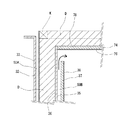
本実施の形態における壁体30は、外壁部30Aと内壁部30Bにより構成され、外壁部30Aと内壁部30Bの間には断熱材Dが充てんされている。また、外壁部30Aと内壁部30Bのそれぞれには空気流通層50A、50Bが形成されている。
First, the
The
外壁部30Aは、複数本の柱および間柱H,MH,H,MH,・・・間にわたって配設された外装下地材となる外側下地材32と、外側下地材32の外表面に所要間隔をあけて上下方向にわたって固定された桟木S1,S1,・・・と、桟木S1,S1,・・・に取り付けられた外装材33により構成されている。
内壁部30Bは、外側下地材32の室内側に所要間隔をあけて並行して配設された内部断熱材下地材となる中間壁35と、中間壁35を保持するための中間壁用間柱CMHと、中間壁35の室内側表面に貼り付けられた防湿シート36と、防湿シート36の表面に所要間隔をあけて上下方向にわたって中間壁35に固定された桟木S2,S2,・・・と、桟木S2,S2,・・・に取り付けられ、内装下地材となる内側下地材37と、内側下地材37に貼り付けられた内装材38により構成されている。
The
The
中間壁35は、柱H,H・・・と並行して所要間隔をあけて立設された中間壁用間柱CMHに固定されている。中間壁用間柱CMHは、柱Hとは独立して自立し、土台、桁、梁等に固定されている。中間壁用間柱CMHの室外側端面位置は、柱Hの室内側端面位置よりも室内側に位置するように配設されている。このように配設した中間壁用間柱CMHにより中間壁35の配設位置が規定され、壁体30に配設される断熱材Dの壁厚方向における充てん幅を設定することができる。中間壁35は柱Hとは独立して配設されているため、任意の位置に配設することができ、断熱材Dの充てん厚さを自由に設定することが可能である。
The
外壁部30Aにおいては外装材33と外側下地材32の間に配設された桟木S1により室外側の空気流通層50Aが形成されている。また、内壁部30Bにおいては、中間壁35と内側下地材37との間に配設された桟木S2により室内側の空気流通層50Bが形成されている。内壁部30Bの空気流通層50Bの下端部は床下空間90に、上端部は天井70に形成された空気流通層80にそれぞれ連通している。そして外側下地材32と中間壁35の間には断熱材Dが充てんされている。したがって壁体30は、室外側および室内側の空気流通層50A,50Bにより断熱材Dがサンドイッチされた断熱構造に形成されている。これにより、断熱効果をさらに向上させることができる。
なお、本実施の形態においては、海綿状の断熱材Dが用いられている。
In the
In the present embodiment, a sponge-like heat insulating material D is used.
次に天井70について説明する。
基本骨組構造の桁Kと、断熱材Dと、断熱材を保持する断熱材保持部72と、天井内装材下地74と天井内装材76により構成されている。
断熱材保持部72は、桁Kに取り付けられた吊り下げ部材(図示せず)に吊り下げられた断熱材保持枠材72a,72bと、断熱材保持枠材72a,72bに取り付けられた断熱材受板72cにより構成されている。断熱材保持枠材72a,72bは格子状に形成されていて、室内側面(下面)に断熱材受板72cが取り付けられている。断熱材受板72cの室内側面(下面)には、防湿シート78が粘着テープ等により取り付けられている。
Next, the
It comprises a girder K having a basic frame structure, a heat insulating material D, a heat insulating
The heat insulating
断熱材受板72cの上面と桁Kの上面の間には断熱材Dが充てんされている。断熱材受板72cの配設位置も自由に設定することができるので、天井70に配設する断熱材Dの設置厚さも自由に設定することができるのである。なお、断熱材受板72cの上に配設される断熱材Dは、必ずしも本実施の形態における配設厚さに限定されるものではなく、桁Kの上面高さ位置まで断熱材Dの配設高さが満たない場合の他、桁Kの上面高さ位置よりも上方位置にまで断熱材Dが配設される場合もある。また、本実施の形態における天井70の断熱材Dには海綿状の断熱材Dが用いられている。
A heat insulating material D is filled between the upper surface of the heat insulating
防湿シート78の下面には所要間隔をあけて桟木S3が取り付けられている。桟木S3の下面には天井内装材下地74が取り付けられ、天井内装材下地74の下面には天井内装材76が取り付けられている。桟木S3,S3,・・・と防湿シート78および天井内装材下地74に囲まれた空間は空気流通層80となり、空気流通層80の両端部は壁体30に形成された室内側の空気流通層50Bにそれぞれ連通している。
A crosspiece S3 is attached to the lower surface of the moisture-
このように、壁体30の室内側空気流通層50Bと天井70の空気流通層80とを互いに連通させることにより、居住空間を空気流通層50B,80により覆った状態にすることができる。床下空間90を半地下構造にしておけば、空気流通層50B,80に流通させる空気を床下空間90で温度調整することができる。これにより夏には冷却した空気を得ることができる。さらに、床下空間90に太陽熱を熱源とする蓄熱装置を配設しておけば、冬には加熱した空気を空気流通層50B,80に流通させることができ、四季を通じて快適な温度設定が可能になる。
As described above, the indoor
さらにまた、床下空間90に空調装置を配設すれば、さらにきめ細かく居住空間内の温度調整を行うことができるためより好適である。
これらの構造を採用する場合には、床下空間90の温度を外気温度と絶縁するために基礎Bの外表面または内表面のいずれか一方または両方に断熱材D2を配設しておくことが好ましい。
Furthermore, it is more preferable to arrange an air conditioner in the
When these structures are employed, it is preferable to dispose a heat insulating material D2 on one or both of the outer surface and the inner surface of the foundation B in order to insulate the temperature of the
また、壁体30および天井70には、断熱材Dよりも室内側に空気流通層50B,80が形成されているので、電気工事や配管工事等の設備工事を行う際に、空気流通層50B,80を配管・配線(またはいずれか一方の)スペースとして使用することができる。これにより、壁体30および天井70に配設した断熱材Dを欠損させることがなくなると共に、断熱材Dを保護する防湿シート36,78を損傷させることもなくなるので、断熱性能は当初の施工状態を維持することができる。
In addition, since the air circulation layers 50B and 80 are formed on the
(第2実施形態)
図4は、第2実施形態における建物の断熱構造の壁体部と天井の接続部分の構造説明図である。
本実施の形態は、天井70に空気流通層を形成しない形態である。壁体30には、第1実施形態と同様に空気流通層50A,50Bが形成されていて、室内側の空気流通層50Bの下端部は床下空間90に連通している。
室内側空気流通層50Bの上端部は、天井70と接続されず、室内空間に開放している。床下空間90から室内側空気流通層50Bを流通した空気は、壁体30の室内側上端部から室内空間に流入することになる。このような形態にすることで、室内空間の空気を直接的に温度調整することができるため、温度調整をきわめて迅速に行うことができる。
(Second Embodiment)
FIG. 4 is an explanatory view of the structure of the connecting portion between the wall portion and the ceiling of the heat insulating structure of the building in the second embodiment.
In the present embodiment, an air circulation layer is not formed on the
The upper end of the indoor
(第3実施形態)
図5は、第3実施形態における建物の断熱構造のうち天井を居住空間側から見上げた図である。
本実施の形態における天井70は、天井内装材下地74の構造に特徴がある。具体的には、断熱材受板72cの室内側面に複数個の枠構造体74aを形成し、各々の枠構造体74aをマトリクス状に配設することにより天井内装材下地74を形成している。このような天井内装材下地74に天井内装材76を取り付ければ、天井70に形成される空気流通層80は縦方向および横方向に形成され、天井70の端辺に接続するすべての壁体30の室内側空気流通層50Bに連通させることができる。これにより、空気流通層50B,80に流通させる空気量を大幅に増やすことができ、室内空間の温度調整を容易に行うことが可能になる。
なお、枠構造体74aは断熱材受板72cに予め取り付けておくことが好ましい。
(Third embodiment)
Drawing 5 is a figure which looked up at the ceiling from the living space side among the heat insulation structures of the building in a 3rd embodiment.
The
The
(第4実施形態)
図6は、第4実施形態における断熱構造を適用した建物の概略を示す説明図である。
本実施形態は、太陽熱を熱源とする太陽熱利用装置22を用い、空気流通層50B,80に流通させる空気を加熱することを特徴としている。本実施の形態においては、建物の断熱効果をさらに高めるため、外断熱材D3が配設されている。外断熱材D3にはパネル状の断熱材が好適に用いられる。いわゆる屋根裏部分に配設された太陽熱利用装置22により熱交換された空気は、壁面30の空気流通層50B内に配設された加熱空気流通管24内を通って床下空間90に供給される。なお、外断熱材D3は配設しなくてもよい場合がある。
(Fourth embodiment)
FIG. 6 is an explanatory diagram showing an outline of a building to which the heat insulating structure in the fourth embodiment is applied.
The present embodiment is characterized in that the solar
本実施の形態によれば、屋根裏部分で太陽熱利用装置22によりあたためられた空気は、加熱空気流通管24内を通って床下空間90に供給された後、加熱空気の上昇により床面60、壁面30、天井70部分にそれぞれ形成された空気流通層を通って、居住空間の温度調節を行った後、再び太陽熱利用装置22によりあたためられ、この経路を循環する。このように、地球環境へ与える負荷がゼロである太陽熱を効率的に利用することができるため、本発明に係る断熱構造10とあいまって地球環境に負荷を与えることなく、快適な居住空間を提供することができる。
なお、図示しないが、加熱空気流通管24の外周面には断熱材を配設しておくことが好ましい。さらに、太陽熱利用装置22または加熱空気流通管24の経路内に送風ファンを配設しておけば、空気流通層内の空気が淀みなく流通するので、効率的に空気をあたためることが可能になる。
According to the present embodiment, the air warmed by the solar
Although not shown, it is preferable to provide a heat insulating material on the outer peripheral surface of the heated
(第5実施形態)
本実施の形態は、図7に示すように室外から新鮮空気を取り込み、空気流通層50B,80に流通させる形態である。本実施の形態は、第2実施形態の変形例ともいえる。
本実施形態においては、屋根20と天井の間の空間に熱交換器100を配設し、室外空気取込管102から取り込んだ外気を熱交換器100で温度調整した後、一旦床下空間90に流入させ、床下空間90から床面60および壁面の空気流通層(50B)に流通させるものである。空気流通層50Bに供給された空気は、室内流入用連通部106から居住空間に流入した後、室外排出用連通部108から室内空気が排出し、室内空気排出管104を通じて室外に排出されるものである。
(Fifth embodiment)
In the present embodiment, as shown in FIG. 7, fresh air is taken from outside and is distributed to the air circulation layers 50 </ b> B and 80. This embodiment can be said to be a modification of the second embodiment.
In the present embodiment, the
本実施の形態においては、熱交換器100として熱交換型の換気扇が用いられている。熱交換器100は、室外排出用連通部108から取り込んだ温かい(または冷たい)室内空気の熱を利用して、室外空気取込管102により取り込まれた室外空気を温めた(または冷ました)後に室内流入用連通部106から居住空間に供給することができる。
本実施形態によれば、常に居住空間の室温に近い状態となるように温度調節された新鮮な空気を居住空間に取り込むことができるため好都合である。
In the present embodiment, a heat exchange type ventilation fan is used as the
According to the present embodiment, it is advantageous because fresh air whose temperature is adjusted so as to be always close to the room temperature of the living space can be taken into the living space.
また、熱交換器100は、熱交換型換気扇のみに限定されるものではなく、例えば図6に示したような太陽熱を熱源とするものの他に、化石燃料を用いた熱交換器100であってもよい。化石燃料を用いる熱交換器100の場合には、図7に示す配設位置よりも床下空間に配設する方が燃料消費により得られる発熱を効率よく利用することができるためより好都合である。
Further, the
(第6実施形態)
図8は第6実施形態における断熱構造を適用した建物の概略を示す説明図である。
本実施形態における建物の断熱構造10は、居住空間における暖房として、太陽熱システムを利用した一例を示す。本実施の形態においては、断熱材Dにより、居住空間および天井部分を覆うようにして、外部との温度の遮断をしている。
屋根20に配設された太陽熱集熱部200と、床下空間90に配設された放熱部210と給湯部220の間には、それぞれに熱媒体(例えば不凍液)を循環させるためのパイプラインPが配設されている。
(Sixth embodiment)
FIG. 8 is an explanatory diagram showing an outline of a building to which the heat insulating structure in the sixth embodiment is applied.
The
A pipeline P for circulating a heat medium (for example, an antifreeze liquid) between the solar
太陽熱集熱部200において加熱された不凍液は、パイプラインPを通じて床下空間90の放熱部210に送られる。不凍液は放熱部210を通過することにより不凍液に蓄えた熱を床下空間90に放出する。床下空間90において放出された熱は床下空間90の空気を加熱し、上昇気流を生じさせ、空気流通層50B,80内を流通し、居住空間内の温度調節を行うのである。
The antifreeze liquid heated in the solar
また、図8に示すように、床下空間90の内表面部分をコンクリートBCにすれば、コンクリートBCの蓄熱作用を利用することができ、床下空間90全体の温度を加熱することができる。また、太陽熱が十分得られる間に蓄熱しておけば、太陽熱が得られ難い状態になった際であってもコンクリートBCに蓄えた熱が放出されるので、放出熱量のバッファとして機能させることもできるため好都合である。
Further, as shown in FIG. 8, if the inner surface portion of the
さらには、放熱部210と給湯部220の間には切替弁(図示せず)が配設されていて、不凍液が給湯部220にも流通可能になっている。切替弁は制御手段により開閉動作が制御されている。制御手段は、室外温度の他、室外温度と室内温度の温度差などの温度条件に応じて切替弁の開閉動作(切替弁のオンオフまたは切替弁の開度)を制御している。制御手段が切替弁を開くと給湯部220に不凍液が流入し、不凍液に蓄えられた熱を給湯部220の熱源として利用することもできる。本実施の形態においては、太陽熱を用いた暖房・給湯の一方または両方を適切に利用することができる。
このように、本実施の形態においては、無償の無限エネルギである太陽熱を利用した暖房および給湯設備を構築することができる。
Furthermore, a switching valve (not shown) is disposed between the
Thus, in this Embodiment, the heating and hot-water supply equipment using the solar heat which is free infinite energy can be constructed | assembled.
以上に、本発明にかかる建物の断熱構造について実施の形態に基づいて詳細に説明してきたが、本発明は、以上の実施の形態に限定されるものではなく、発明の主旨を逸脱しない範囲において各種の変更を行ったとしても本発明の技術的範囲に属することはもちろんである。
例えば、断熱材Dを保護するための防湿シート36,78は、中間壁35または断熱材受板72cにおいて、直接断熱材Dに接するように配設する形態の他、直接断熱材Dと接しないように中間壁35または断熱材受板72cの室内側に配設する形態のいずれの形態であってもよい。また、断熱材Dの配設厚さが十分に厚い場合には、防湿シート36,78は配設しなくても済むことがある。
As mentioned above, although the heat insulation structure of the building concerning this invention has been demonstrated in detail based on embodiment, this invention is not limited to the above embodiment, In the range which does not deviate from the main point of invention. It goes without saying that even if various modifications are made, they belong to the technical scope of the present invention.
For example, the moisture-
また、以上に説明した実施形態においては、壁体30には必ず室内側に空気流通層50Bが形成されているが、室内側の空気流通層50Bは必ずしも形成しなくても良い。室内側の空気流通層50Bを形成しない場合には、中間壁35が不要になり、中間壁用間柱CMHに直接内側下地材37を取り付ければよい。この場合、電気工事等の設備工事を行うためのスペースがなくなってしまうが、当初に配設する断熱材Dの充てん厚さを、設備工事により欠損してしまう断熱材Dの厚さ分だけ予め上乗せしておくと共に、防湿シート36の養生を確実に行うことにより当初課題に対応することができる。
In the embodiment described above, the
また、以上の実施の形態においては、断熱材配設空間を形成する外側下地材32と内側下地材37は、いわゆる内断熱構造となるようにそれぞれ配設されているが、外側下地材32および内側下地材37を柱Hの位置よりも室外側に配設し、いわゆる外断熱構造にすることもできる。これによれば、外断熱構造であっても、断熱材の配設厚さを任意の厚さに設定することができるため好適である。
さらには、外断熱構造を採用する際においても海綿状の断熱材を用いることができるので、断熱材の設置厚さを大幅に増やすことができ、断熱性能を大幅に向上させることができる。
Further, in the above embodiment, the
Furthermore, since a sponge-like heat insulating material can be used even when the outer heat insulating structure is adopted, the installation thickness of the heat insulating material can be greatly increased, and the heat insulating performance can be greatly improved.
以上に説明した実施形態の他、上記実施形態のすべてを組み合わせた形態としてもよいことは云うまでもない。 Needless to say, in addition to the embodiments described above, all of the above embodiments may be combined.
10 建物
20 屋根
22 太陽熱利用装置
24 加熱空気流通管
30 壁体
30A 外壁部
30B 内壁部
32 外側下地材(外装下地材)
33 外装材
35 中間壁(内部断熱下地材)
36,78 防湿シート
37 内側下地材(内装下地材)
38 内装材
50A,50B,80 空気流通層
60 床
70 天井
72 断熱材保持部
74 天井内装材下地
76 天井内装材
90 床下空間
100 熱交換器
102 室外空気取込管
104 室内空気排出管
106 室内流入用連通部
108 室外流出用連通部
200 太陽熱集熱部
210 放熱部
220 給湯部
B 基礎
BC コンクリート
C 被覆材
D,D2,D3 断熱材
H 柱
K 桁
MH 間柱
P パイプライン
S1,S2,S3 桟木
DESCRIPTION OF
33
36, 78 Moisture-
38
Claims (6)
前記外側下地材と前記内側下地材は、柱と独立した任意の位置に配設されていることを特徴とする建物の断熱構造。 In the heat insulating structure of the building in which an outer base material and an inner base material are arranged, and a heat insulating material is arranged between the outer base material and the inner base material,
The heat insulating structure for a building, wherein the outer base material and the inner base material are arranged at arbitrary positions independent of the pillars.
前記断熱材が前記外側下地材と前記中間壁との間に配設されていることを特徴とする請求項1記載の建物の断熱構造。 An intermediate wall is provided between the outer base material and the inner base material,
The heat insulating structure for a building according to claim 1, wherein the heat insulating material is disposed between the outer base material and the intermediate wall.
Priority Applications (1)
| Application Number | Priority Date | Filing Date | Title |
|---|---|---|---|
| JP2008062997A JP2008150946A (en) | 2008-03-12 | 2008-03-12 | Heat insulation structure of building |
Applications Claiming Priority (1)
| Application Number | Priority Date | Filing Date | Title |
|---|---|---|---|
| JP2008062997A JP2008150946A (en) | 2008-03-12 | 2008-03-12 | Heat insulation structure of building |
Related Parent Applications (1)
| Application Number | Title | Priority Date | Filing Date |
|---|---|---|---|
| JP2005334738A Division JP4163206B2 (en) | 2005-11-18 | 2005-11-18 | Thermal insulation structure of building |
Publications (2)
| Publication Number | Publication Date |
|---|---|
| JP2008150946A true JP2008150946A (en) | 2008-07-03 |
| JP2008150946A5 JP2008150946A5 (en) | 2009-01-08 |
Family
ID=39653405
Family Applications (1)
| Application Number | Title | Priority Date | Filing Date |
|---|---|---|---|
| JP2008062997A Pending JP2008150946A (en) | 2008-03-12 | 2008-03-12 | Heat insulation structure of building |
Country Status (1)
| Country | Link |
|---|---|
| JP (1) | JP2008150946A (en) |
Citations (9)
| Publication number | Priority date | Publication date | Assignee | Title |
|---|---|---|---|---|
| JP2543657B2 (en) * | 1993-06-21 | 1996-10-16 | 英晴 相澤 | Building wall structure |
| JPH08312019A (en) * | 1995-05-17 | 1996-11-26 | Sekisui House Ltd | Heat insulating device of roof and outer wall |
| JPH09228492A (en) * | 1996-02-22 | 1997-09-02 | Emoto Kogyo Kk | Structure panel and dampproof structure of building |
| JPH1113167A (en) * | 1997-06-25 | 1999-01-19 | Fukuvi Chem Ind Co Ltd | Wall panel and building using it |
| JP2849228B2 (en) * | 1991-04-08 | 1999-01-20 | ダウ化工株式会社 | Architectural panel, wooden building comprising the architectural panel, and construction method thereof |
| JP2905417B2 (en) * | 1995-04-14 | 1999-06-14 | 英晴 相澤 | Air circulation building |
| JP2918514B2 (en) * | 1997-06-17 | 1999-07-12 | 松本建工株式会社 | Prevention structure of the cold bridge of the first floor concrete part in the outside insulation steel frame building |
| JPH11336213A (en) * | 1998-05-29 | 1999-12-07 | Kubota Corp | Method and structure for heat insulation of building wall |
| JP2001271433A (en) * | 2000-03-24 | 2001-10-05 | Fukuchi Kenso:Kk | External heat insulating board for bearing wall |
-
2008
- 2008-03-12 JP JP2008062997A patent/JP2008150946A/en active Pending
Patent Citations (9)
| Publication number | Priority date | Publication date | Assignee | Title |
|---|---|---|---|---|
| JP2849228B2 (en) * | 1991-04-08 | 1999-01-20 | ダウ化工株式会社 | Architectural panel, wooden building comprising the architectural panel, and construction method thereof |
| JP2543657B2 (en) * | 1993-06-21 | 1996-10-16 | 英晴 相澤 | Building wall structure |
| JP2905417B2 (en) * | 1995-04-14 | 1999-06-14 | 英晴 相澤 | Air circulation building |
| JPH08312019A (en) * | 1995-05-17 | 1996-11-26 | Sekisui House Ltd | Heat insulating device of roof and outer wall |
| JPH09228492A (en) * | 1996-02-22 | 1997-09-02 | Emoto Kogyo Kk | Structure panel and dampproof structure of building |
| JP2918514B2 (en) * | 1997-06-17 | 1999-07-12 | 松本建工株式会社 | Prevention structure of the cold bridge of the first floor concrete part in the outside insulation steel frame building |
| JPH1113167A (en) * | 1997-06-25 | 1999-01-19 | Fukuvi Chem Ind Co Ltd | Wall panel and building using it |
| JPH11336213A (en) * | 1998-05-29 | 1999-12-07 | Kubota Corp | Method and structure for heat insulation of building wall |
| JP2001271433A (en) * | 2000-03-24 | 2001-10-05 | Fukuchi Kenso:Kk | External heat insulating board for bearing wall |
Similar Documents
| Publication | Publication Date | Title |
|---|---|---|
| US20100198414A1 (en) | Systems and methods for controlling interior climates | |
| US20090001185A1 (en) | Structural wall panels and methods and systems for controlling interior climates | |
| EP2089661B1 (en) | Low energy consumption climate control system | |
| EA004624B1 (en) | Air conditioning system for buildings and air-conditioned building, especially a zero energy house | |
| JP2010223522A (en) | Floor heating system and heat storage unit | |
| JP2008076015A (en) | Building air-conditioning system by geothermal use | |
| JP4785098B2 (en) | Underground heat exchanger buried structure | |
| JP2009192185A (en) | Air conditioning ventilation system | |
| EP3645802B1 (en) | Geothermal insulation system and method | |
| JP6135905B2 (en) | Earth / Solar system | |
| JP2005061786A (en) | Indoor temperature adjusting structure using geotherm | |
| JP2007070893A (en) | Steel house | |
| JP2010151351A (en) | Underground heat exchanger burying structure | |
| JP4163206B2 (en) | Thermal insulation structure of building | |
| JP2008150946A (en) | Heat insulation structure of building | |
| JP5505837B2 (en) | Earth / Solar system (basement compatible) | |
| JP2005042511A (en) | Rc heat storage air conditioning system and its method of construction | |
| JP2014015711A (en) | Radiant heat heating and cooling system of building utilizing in-wall-body vent layer | |
| JP2007139236A (en) | Underfloor air-conditioning device and method | |
| JP2005163482A (en) | Ventilation system for building | |
| JP2015137782A (en) | indoor air reflux system | |
| US20080121367A1 (en) | Reduction Of Power Consumption | |
| JP6135907B2 (en) | Earth / Solar system | |
| JP2001020403A (en) | Heat storage type footing and structure of building having the same | |
| JP3165610U (en) | Thermal storage floor heating system |
Legal Events
| Date | Code | Title | Description |
|---|---|---|---|
| A521 | Written amendment |
Free format text: JAPANESE INTERMEDIATE CODE: A523 Effective date: 20081114 |
|
| A621 | Written request for application examination |
Free format text: JAPANESE INTERMEDIATE CODE: A621 Effective date: 20081114 |
|
| A131 | Notification of reasons for refusal |
Free format text: JAPANESE INTERMEDIATE CODE: A131 Effective date: 20111108 |
|
| A521 | Written amendment |
Free format text: JAPANESE INTERMEDIATE CODE: A523 Effective date: 20120110 |
|
| A02 | Decision of refusal |
Free format text: JAPANESE INTERMEDIATE CODE: A02 Effective date: 20130108 |