JP2008143637A - Chopper folding device - Google Patents
Chopper folding device Download PDFInfo
- Publication number
- JP2008143637A JP2008143637A JP2006331481A JP2006331481A JP2008143637A JP 2008143637 A JP2008143637 A JP 2008143637A JP 2006331481 A JP2006331481 A JP 2006331481A JP 2006331481 A JP2006331481 A JP 2006331481A JP 2008143637 A JP2008143637 A JP 2008143637A
- Authority
- JP
- Japan
- Prior art keywords
- chopper
- chopper blade
- folding device
- blade
- support shaft
- Prior art date
- Legal status (The legal status is an assumption and is not a legal conclusion. Google has not performed a legal analysis and makes no representation as to the accuracy of the status listed.)
- Ceased
Links
Images


Abstract
Description
本発明は、輪転印刷機に付設される折機におけるチョッパ折り装置に関する。 The present invention relates to a chopper folding device in a folding machine attached to a rotary printing press.
巻紙輪転印刷機には、印刷後、乾燥冷却されたウェブを所定の長さごとに断裁したり、これを幅方向又は長さ方向に折ったりする折機が備えられている。この折機による折り方には、断裁前のウェブをフォーマで幅方向に半折りするフォーマ折りと、断裁後の折丁を折胴とくわえ胴との間で長さ方向に半折りする平行1回折り、又は、平行1回折りされた折丁をさらにくわえ胴と第2くわえ胴との間で長さ方向に折ることで4つ折りしたりする平行2回折りと、平行1回折り又は平行2回折りされた折丁をチョッパで直交方向へ半折りするチョッパ折りと、がある。これらの折り方は、折丁の仕様にしたがい選択されて単独で用いられたり、このうちの幾つかが組み合わされたりする。 The web-fed rotary printing press is provided with a folding machine that cuts the dried and cooled web every predetermined length after printing or folds the web in the width direction or the length direction. For folding by this folding machine, a former fold in which the web before cutting is half-folded in the width direction with a former, and a folded signature is half-folded in the length direction between the folding cylinder and the holding cylinder in parallel 1 Parallel folding that is folded in four or by folding the signature that has been folded once in parallel between the holding cylinder and the second holding cylinder in the length direction, and folded in parallel, or in parallel 1 or There is chopper folding in which a folded signature is folded in half in the orthogonal direction by a chopper. These folding methods are selected according to the specifications of the signature and used alone, or some of them are combined.
前記各折装置のうちのチョッパ折り装置は、搬送ベルトで搬送中の折丁を紙当てに当てると共に折丁の中央部へ向って略垂直姿勢で下降してくる板状のチョッパブレードで折丁を中央から折りながら下方のニッピングローラ間へ押し込むことにより半折りするものであり、特許文献1や特許文献2等で周知である。 Among the folding devices, the chopper folding device is a plate-like chopper blade that applies the signature being conveyed by the conveyance belt to the paper pad and descends in a substantially vertical posture toward the central portion of the signature. Is folded halfway by being pushed between the lower nipping rollers while being folded from the center, and is well known in Patent Document 1, Patent Document 2, and the like.
ところで、前記チョッパ折り装置では、図16に示すように、ニッピングローラ100a,100b間に折丁を円滑に引き込ませるのには、チョッパブレード101の最深位置(最下点)でのローラ面との隙間h1,h2が重要となる。即ち、ニッピングローラ100a,100bは圧縮コイルばね(図示略)により互いに接近する方向に常に付勢されていることから、隙間h1,h2が、引き込まれる折丁より小さければ、大きな圧力が生じ、振動や折丁への傷,擦れが懸念される。一方、隙間h1,h2が大きければ、折丁を引き込むに足り得る摩擦力が発生せず、折丁は引き込まれないのである。
By the way, in the chopper folding device, as shown in FIG. 16, in order to smoothly draw the signature between the
そして、チョッパブレード101の最深位置は、紙質、紙厚、折仕様(平行1回折り、平行2回折り)などにより異なると共に、チョッパブレード101の先端が摩耗し最深位置が変わって来ることから、従来は、機械始動前に、チョッパアーム(図示略)にチョッパブレード101をボルトで取り付ける際のボルト挿通孔の公差を利用し、当該ボルトを締め直すなどして位置調整を行い、印刷時には、その調整されたチョッパブレード101でチョッパ折りしていた。
And the deepest position of the
ところで、従前から、印刷時における機械回転速度の低速時は、紙の慣性が小さく搬送ベルトなどの抵抗によってニッピングローラ100a,100b間に紙が引き込まれ難いため、ニッピングローラ100a,100b間にチョッパブレード101をできるだけ接近させたいという要求があった。反対に、機械回転速度の高速時は、紙の慣性が大きく搬送ベルトなどの抵抗をほとんど受けず、チョッパブレード101がニッピングローラ100a,100b間に近すぎることによりニッピングローラ100a,100b間で紙つまりがし易くなるため、ニッピングローラ100a,100b間からチョッパブレード101を離間させたいという要求があった。
By the way, from the past, when the machine rotation speed at the time of printing is low, since the inertia of the paper is small and it is difficult to draw the paper between the
しかしながら、従来は、上記一方の位置に調整すると他方の位置にできないことの問題点が発生し、他方の位置に調整すると一方の位置にできないことの問題が発生するので、これらの調整を行うことができなかった。 However, conventionally, when adjusting to the one position, the problem that the other position cannot be obtained occurs, and when adjusting to the other position, the problem that the other position cannot be obtained occurs. I could not.
本発明は、上記状況に鑑み提案されたもので、チョッパブレードの最深位置を少なくとも機械回転速度に応じて自動で調整できるチョッパ折り装置を提供することを目的とする。 The present invention has been proposed in view of the above situation, and an object thereof is to provide a chopper folding device capable of automatically adjusting the deepest position of the chopper blade according to at least the mechanical rotation speed.
前述した課題を解決するための、本発明に係るチョッパ折り装置は、搬送されるシート状物の上方の位置に位置付けられた第1の位置と、シート状物の下方の位置において対向する一対のニッピングローラ間にシート状物を押し込む第2の位置との間で移動するチョッパブレードを備えたチョッパ折り装置において、前記チョッパブレードの前記第2の位置を上下方向に調整する移動手段を備え、前記移動手段を、前記チョッパ折り装置が所定の回転速度のとき、または前記チョッパ折り装置が所定の回転速度を超えたときに、前記チョッパブレードの前記第2の位置を上方へ移動させるように動作させる制御手段を備えたことを特徴とする。 In order to solve the above-described problem, a chopper folding device according to the present invention includes a pair of opposed first and second positions positioned at a position above a sheet-like material to be conveyed and a position below the sheet-like material. In a chopper folding device including a chopper blade that moves between a second position for pushing a sheet-like material between nipping rollers, the chopper blade includes a moving means that adjusts the second position of the chopper blade in the vertical direction, The moving means is operated to move the second position of the chopper blade upward when the chopper folding device is at a predetermined rotational speed or when the chopper folding device exceeds a predetermined rotational speed. Control means is provided.
また、前記移動手段は、前記チョッパブレードを支持する支持軸と、前記支持軸を移動させて前記第2の位置を上下方向に調整する第1の駆動手段とからなることを特徴とする。 The moving means includes a support shaft that supports the chopper blade, and first driving means that moves the support shaft to adjust the second position in the vertical direction.
また、前記支持軸は、前記支持軸の中心から偏心した偏心軸を有し、前記第1の駆動手段は、前記偏心軸を回動させることを特徴とする。 Further, the support shaft has an eccentric shaft that is eccentric from the center of the support shaft, and the first drive means rotates the eccentric shaft.
また、前記支持軸を中心に前記チョッパブレードを、クランク機構を介して前記第1の位置と前記第2の位置との間で移動させる第2の駆動手段を備え、前記第1の駆動手段の動作と前記クランク機構によって、前記第2の位置における前記チョッパブレードの先端は、ほぼ鉛直方向に移動調整されることを特徴とする。 And a second driving unit configured to move the chopper blade between the first position and the second position via a crank mechanism with the support shaft as a center. By the operation and the crank mechanism, the tip of the chopper blade in the second position is adjusted to move in a substantially vertical direction.
また、前記クランク機構は、前記チョッパブレードを支持して前記支持軸を中心に回動するチョッパブレード本体と、前記駆動手段の回転部から偏心した偏心部と、前記チョッパブレード本体に一方側が取り付けられると共に前記偏心部に他方側が取り付けられたロッドとからなることを特徴とする。 The crank mechanism includes a chopper blade body that supports the chopper blade and rotates around the support shaft, an eccentric portion that is eccentric from a rotating portion of the driving means, and one side that is attached to the chopper blade body. And a rod having the other side attached to the eccentric portion.
本発明に係るチョッパ折り装置によれば、一対のニッピングローラ間にシート状物を押し込む第2の位置が、機械回転速度(チョッパ折り装置の回転速度)が低速域から高速域になるにつれて、上方へ自動で移動させられ、常に最適位置に調整される。 According to the chopper folding device according to the present invention, the second position where the sheet-like material is pushed between the pair of nipping rollers moves upward as the mechanical rotational speed (rotational speed of the chopper folding device) changes from the low speed range to the high speed range. Is automatically adjusted to the optimal position.
以下、本発明に係るチョッパ折り装置を実施例により図面を用いて詳細に説明する。 DESCRIPTION OF EMBODIMENTS Hereinafter, a chopper folding device according to the present invention will be described in detail with reference to the drawings by way of examples.
図1は本発明の実施例1を示すチョッパ折り装置の正断面図、図2は図1の要部平面図、図3は図2のIII矢視図、図4はチョッパアーム部の平面図、図5は図4の正断面図、図6は図4の側断面図、図7は制御ブロック図、図8は動作フロー図、図9はチョッパ折り装置の正面模式図、図10はチョッパ折り装置のアップ調整時の正面模式図、図11はチョッパ折り装置のダウン調整時の正面模式図、図12はブレード先端の軌跡図である。 FIG. 1 is a front sectional view of a chopper folding device showing Embodiment 1 of the present invention, FIG. 2 is a plan view of the main part of FIG. 1, FIG. 3 is a view taken along the arrow III in FIG. 5 is a front sectional view of FIG. 4, FIG. 6 is a side sectional view of FIG. 4, FIG. 7 is a control block diagram, FIG. 8 is an operation flowchart, FIG. 9 is a front schematic view of a chopper folding device, and FIG. 11 is a schematic front view when the folding device is adjusted up, FIG. 11 is a schematic front view when the chopper folding device is adjusted down, and FIG. 12 is a locus diagram of the blade tip.
図1に示すように、折胴とくわえ胴との間で平行1回折り、又は、平行1回折りされた折丁をさらにくわえ胴と第2くわえ胴との間で平行2回折りされた折丁(シート状物)Wは、プレート10上を上,下搬送ベルト11a,11bにより搬送されてくる。プレート10には折丁搬送方向に沿ってその幅方向略中央部にスリット12が形成され、そのスリット12に臨んで相対向するプレート10の縁部に折丁Wをスリット12から下方へ導く口金13がそれぞれ取り付けられている。
As shown in FIG. 1, the parallel one-fold diffraction was performed between the folding cylinder and the holding cylinder, or the signature subjected to the parallel one-folding was further subjected to two parallel diffractions between the holding cylinder and the second holding cylinder. The signature (sheet-like material) W is conveyed on the
口金13の下方には、後述する最深位置(最下点)におけるチョッパブレード14の直下に位置して、一対のニッピングローラ15a,15bが配設されており、これらのニッピングローラ15a,15bはそれぞれレバー16a,16bに自動調心ころ軸受(図示略)を介して軸支されている。尚、図1においては、ニッピングローラ15a,15bの一端側のレバー16a,16bに関してのみ図示されているが、両ニッピングローラ15a,15bの他端側も同じ構成のレバーに軸支されると共に以下に述べる機構部と同じ機構部を有している。
Below the
これらのレバー16a,16bは折機フレーム17に固定された支持軸18a,18bに回動自在に支持されており、両レバー16a,16bが支持軸18a,18bを中心として揺動することで両ニッピングローラ15a,15bの位置が移動するようになっている。両ニッピングローラ15a,15bの軸端には各々駆動歯車(図示略)が固定されると共に、これらの駆動歯車が支持軸18a,18bに軸支された中間歯車(図示略)とそれぞれ噛み合っており、これらの中間歯車が折機フレーム側に固設された駆動モータ(図示略)に歯車列を介して連結されている。従って、レバー16a,16bの揺動位置に関係なく、駆動モータの回転はニッピングローラ15a,15bに伝えられ、それを回転駆動する。
These
レバー16a,16bの下端部にはそれぞれボス部19a,19bが形成され、そこに穿設された孔にシャフト20が揺動自在に貫通している。このシャフト20は折機フレーム17に軸方向摺動自在に且つ軸回りに回動自在に支持されており、その一端は折機フレーム内に固定されたブラケット21に支持されると共に他端は折機フレーム17の外部まで延出して先端に操作ダイアル22が固定されている。
また、両レバー16a,16bのボス部19a,19bの間のシャフト20には折丁Wに対して折り目を付けるための押圧力を発生させる圧縮コイルばね23が巻装され、この圧縮コイルばね23の両端が両ボス部19a,19bに当接してそれらを互いに離反する方向、つまり両ニッピングローラ15a,15bを互いに接近させる方向に付勢している。
The
さらに、これらのボス部19a,19bの外側には各々駒24a,24bが配置され、シャフト20に刻設された右ねじ部(図示略)及び左ねじ部(図示略)にそれぞれ螺合している。これらの駒24a,24bは圧縮コイルばね23に付勢されたボス部19a,19bにそれぞれ当接してそれらの外側への移動を規制すると共に、駒24a,24b自身は折機フレーム17に対して軸方向に移動できるが軸回りには回動できないように保持されている。
Further,
従って、紙質、紙厚、折仕様(平行1回折り、平行2回折り)等に応じて両ニッピングローラ15a,15b間の隙間を変更するには、シャフト20の一端に設けられた操作ダイアル22を操作してシャフト20を回動させる。シャフト20が回動すると、両駒24a,24bがシャフト20上を互いに接近あるいは離反する方向に移動し、それによって両レバー16a,16bが互いに反対方向に揺動することで両ニッピングローラ15a,15b間の隙間を変化させることができる。ここで、両駒24a,24bの移動はそれらの間の中央線(チョッパブレード14の位置)に対して対称であるので、両ニッピングローラ15a,15bの隙間が変化しても、チョッパブレード14を常に両ニッピングローラ15a,15bの隙間の中心に位置させることが可能である。
Therefore, in order to change the gap between the
また、シャフト20には、シャフト20を軸方向に微動させることで、両ニッピングローラ15a,15bの互いの接触線をチョッパブレード14の直下にしかもそれと平行に位置させるための移動手段25が設けられるが、本出願人による特許文献2を参照してここでは説明を省略する。尚、図1中26は羽根車で、両ニッピングローラ15a,15b間で折り目を付けられて落下する折丁Wを、その回転下で順次各羽根間に受容した後、コンベア(図示略)上に排出するようになっている。
Further, the
図2乃至図6に示すように、前記チョッパブレード14はチョッパアーム28の先端部に、アーム軸線に対し直角方向に、ボルト29により取り付けられる。チョッパアーム28の基端部には軸受筒(チョッパブレード本体)30が一体的に付設され、この軸受筒30が折機フレーム17にその両端部において回動可能でかつ所定の回動位置で固定可能に支持された軸31上に嵌装されている。軸31は、ベアリング32を介して軸受筒30を回転可能に支持する支持軸部(支持軸)31aと、該支持軸部31aから偏心した偏心軸部(偏心軸)31bから構成されている。
As shown in FIGS. 2 to 6, the
前記軸受筒30の折機フレーム17に近接した側の端部にはロッカアーム33のリング状端部33aが、軸31の支持軸部31aを遊嵌して、複数のボルト34により固設される。ロッカアーム33の二股状端部33bにはコネクティングロッド(ロッド)35の一端部がピン36により回動自在に結合され、このコネクティングロッド35の他端部が回転部37と共に回転してこの回転部37から偏心したピン(偏心部)38により回動自在に結合される。回転部37は折機フレーム17に固設された駆動モータ39により回転駆動される。従って、前記ロッカアーム33とコネクティングロッド35と回転部37及びピン38からなるクランク機構を介して駆動モータ(駆動手段)39による回転運動が、同じくロッカアーム33と軸受筒30とチョッパアーム28とからなるチョッパブレード本体の往復運動(チョッパブレード14の上下動)に変換されるのである。
A ring-shaped
図2及び図3に示すように、前記軸31のロッカアーム33が遊嵌した側の偏心軸部31bは、折機フレーム17上にボルト41で固定された割軸受40に回動自在に軸支される一方、その反対側の偏心軸部31bは、折機フレーム17間に架設されたスティ42の軸受部42aに回動自在に軸支される。
As shown in FIGS. 2 and 3, the
また、前記軸31のロッカアーム33が遊嵌した側の偏心軸部31bには、歯車列51を介してチョッパブレード調整用モータ(第1の駆動手段)50とチョッパブレード用ロータリーエンコーダ52が組み付けられ、モータ50により軸31を正転又は逆転させられると共にその回転量(角)がロータリーエンコーダ52で検出可能になっている。即ち、前記軸31の回転によりその支持軸部31aが偏心回転し、後述するように前述したクランク機構等との兼ね合いで、チョッパブレード14の最深位置(最下点)が調整可能となるのである。従って、前記支持軸部31aと偏心軸部31bと歯車列51とチョッパブレード調整用モータ50とから移動手段が構成されると共に、前記チョッパブレード14の最深位置(最下点)が一対のニッピングローラ15a,15b間に折丁Wを押し込む第2の位置であり、それ以前の上方位置が第1の位置である。
A chopper blade adjusting motor (first driving means) 50 and a chopper
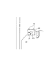
詳述すると、図9に示すように、割軸受40の軸受部40aとスティ42の軸受部42aとに軸支された偏心軸部31b,31bの中心(エキセン芯)C1の外側(チョッパブレード14と反対側)でかつ水平(真横)に、軸31の支持軸部31aの中心(回転芯)C2が位置した状態の時のチョッパブレード14の位置を基準の最深位置(最下点)とする。尚、図9中Lは支持軸部31aの偏心量である。
More specifically, as shown in FIG. 9, the outer side (chopper blade 14) of the center (extension core) C1 of the
この状態から、例えばチョッパブレード14の先端を上げたい場合(アップ調整時)は、偏心軸部31bを図10に示す矢印方向(時計方向)に回動すれば良い。これに伴い、軸31の支持軸部31aに軸受筒30を介して支持されたチョッパアーム28及びこれと一体動するロッカアーム33も偏心回転により同方向に回動しようとする(図10中の鎖線矢印と図12中のチョッパブレード14の先端TBの変位D1参照)。
From this state, for example, when it is desired to raise the tip of the chopper blade 14 (during adjustment), the
ところが、チョッパアーム28及びロッカアーム33が上記方向に回動しようとしても、同ロッカアーム33は長さ不変のコネクティングロッド35と回転部37及びピン38でリンクされているため、チョッパアーム28及びロッカアーム33が図10中の実線矢印方向に回動し、チョッパアーム28にボルト29(図4及び図5参照)で締結されたチョッパブレード14の先端TBも同方向へ移動する(図12中のチョッパブレード14の先端TBの変位D2参照)。
However, even if the
これらの結果、上記変位D1,D2の合算(図12の実線矢印参照)により、チョッパブレード14の先端TBは上下方向に大きく変位して所定の上昇量(図12の上昇量HU参照)が得られる一方、左右方向(スリット12(図1参照)の幅方向)への変位は、実使用上その影響がでない範囲に抑えることができる。
As a result, the tip TB of the
反対に、図9に示す基準の最深位置(最下点)からチョッパブレード14の先端を下げたい場合(ダウン調整時)は、偏心軸部31bを、図11中反時計方向に所定の角度まで回動させる。
Conversely, when it is desired to lower the tip of the
これにより、軸31の支持軸部31aに軸受筒30を介して支持されたチョッパアーム28及びこれと一体動するロッカアーム33も偏心回転により同方向に回動しようとする(図11中の鎖線矢印と図12中のチョッパブレード14の先端TBの変位D1′参照)。
As a result, the
ところが、チョッパアーム28及びロッカアーム33が上記方向に回動しようとしても、同ロッカアーム33は長さ不変のコネクティングロッド35と回転部37及びピン38でリンクされているため、チョッパアーム28及びロッカアーム33が図11中の実線矢印方向に回動し、チョッパアーム28にボルト29(図4及び図5参照)で締結されたチョッパブレード14の先端TBも同方向へ移動する(図12中のチョッパブレード14の先端TBの変位D2′参照)。
However, even if the
これらの結果、上記変位D1′,D2′の合算(図12の実線矢印参照)により、チョッパブレード14の先端TBは上下方向に大きく変位して所定の下降量(図12の下降量HD参照)が得られる一方、左右方向(スリット12(図1参照)の幅方向)への変位は、実使用上その影響がでない範囲に抑えることができる。
As a result, the tip TB of the
そして、本実施例では、図7に示すように、前記モータ50は本機駆動用モータ54と共に制御装置(制御手段)53に駆動制御される。この制御装置53には、チョッパブレード14の最深位置を切り換える機械回転速度を設定し得る回転速度設定変更入力部55と、紙質、紙厚、折仕様(平行1回折り、平行2回折り)などのデータが入力されるウェブデータ入力部56と、機械運転ボタン57と、機械停止ボタン58と、前述したチョッパブレード用ロータリーエンコーダ52と、機械回転速度検出用ロータリーエンコーダ59とからの信号が入力される。
In this embodiment, as shown in FIG. 7, the
前記制御装置53は、紙質、紙厚、折仕様(平行1回折り、平行2回折り)などの諸条件に加えて機械回転速度に応じてモータ50を駆動制御し、チョッパブレード14の最深位置を最適に制御するようになっている。
The
このように構成されるため、チョッパ折り装置においては、チョッパブレード14を支持するチョッパアーム28が軸31の支持軸部31aに回動自在に支持されると共に、ロッカアーム33とコネクティングロッド35と回転部37及びピン38からなるクランク機構を介して駆動モータ39により折丁Wの搬入と同期して駆動されてチョッパブレード14を両口金13の隙間に向けて略上下方向に移動させる。
Thus, in the chopper folding device, the
そして、プレート10上を搬入されてきた折丁Wは、チョッパブレード14の下降によって両ニッピングローラ15a,15bの間に押し込まれると共に、押し込まれた折丁Wは両ニッピングローラ15a,15b間で圧力を加えられて半折りにされた後、順次回転下の羽根車26に落下し、その後、コンベア上に排出されるのは前述したとおりである。
The signature W carried in on the
ところで、チョッパブレード14の最深位置は、前述したように紙質、紙厚、折仕様(平行1回折り、平行2回折り)などに加えて機械回転速度に応じて調整することが必要とされる。
By the way, the deepest position of the
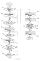
そこで、本実施例では、制御装置53によりモータ50を前述したように駆動制御し、チョッパブレード14の最深位置を最適に制御するようになっている。即ち、前記モータ50は図8に示す動作フロー図に基づいて制御されるのである。
Therefore, in this embodiment, the
詳述すると、先ず、ステップP1で設定された回転速度を変更するか否かを判断し、可であればステップP2で変更する回転速度を回転速度設定変更入力部55に入力した後、ステップP3でウェブデータ入力部56に紙質、紙厚などのウェブデータを入力する一方、否であればステップP3に直接移行する。
Specifically, it is first determined whether or not to change the rotational speed set in step P1, and if yes, the rotational speed to be changed in step P2 is input to the rotational speed setting
次に、ステップP4でチョッパブレード調整用モータ50を駆動し、ステップP5でチョッパブレード14がウェブデータに応じた低速域の最下点位置へ移動したら、ステップP6でチョッパブレード調整用モータ50が停止される。
Next, the chopper
次に、ステップP7で機械運転ボタン57がONされた後、ステップP8で本機駆動用モータ54が駆動され、ステップP9で現在の回転速度が設定回転速度又は変更された回転速度を上回ったら、ステップP10でチョッパブレード調整用モータ50が駆動される。
Next, after the
次に、ステップP11でチョッパブレード14がウェブデータに応じた高速域の最下点位置へ移動したら、ステップP12でチョッパブレード調整用モータ50を停止する。
Next, when the
次に、ステップP13で機械停止ボタン58がONされた後、ステップP14で本機駆動用モータ54が停止され、ステップP15で現在の回転速度が設定回転速度又は変更された回転速度を下回ったら、ステップP16でチョッパブレード調整用モータ50が駆動される。
Next, after the
次に、ステップP17でチョッパブレード14がウェブデータに応じた低速域の最下点位置へ移動したら、ステップP18でチョッパブレード調整用モータ50を停止して動作を終了する。以後、これを繰り返すのである。
Next, when the
このようにして、本実施例では、紙質、紙厚、折仕様(平行1回折り、平行2回折り)などの諸条件に加えて機械回転速度に応じ、例えば低速域(停止状態から極めて遅い速度である緩動運転)はチョッパブレード14の最深位置を下げ、高速域には逆に最深位置を上げることが自動的に行われ、これにより、低速域では折丁Wが両ニッピングローラ15a,15b間に円滑に引き込まれる一方、高速域では両ニッピングローラ15a,15bの振動や折丁Wへの傷,擦れの発生が未然に回避され、ニッピングローラ15a,15b間で紙つまりを起こすことがない。
Thus, in this embodiment, in accordance with the machine rotation speed in addition to various conditions such as paper quality, paper thickness, folding specifications (parallel 1 diffraction, parallel 2 diffraction), etc., for example, the low speed range (extremely slow from the stop state). In the slow running mode), the deepest position of the
また、制御装置53においては、システムを容易にアップデートすることができると共に、各種データを必要に応じてプリセットすることもできる。
In the
図13は本発明の実施例2を示すチョッパ折り装置の要部背面図、図14は制御ブロック図、図15は動作フロー図である。 FIG. 13 is a main part rear view of a chopper folding device showing Embodiment 2 of the present invention, FIG. 14 is a control block diagram, and FIG. 15 is an operation flow diagram.
これは、図13に示すように、実施例1におけるチョッパブレード調整用モータ50に代えて、軸31の偏心軸部31bをレバー61を介してチョッパブレード調整用エアシリンダ60により回転駆動して、チョッパブレード14の最深位置の調整を制御装置53により自動化し得るようにした例である。従って、前記軸31とレバー61とチョッパブレード調整用エアシリンダ60とから移動手段が構成される。
As shown in FIG. 13, instead of the chopper
制御装置53には、図14に示すように、チョッパブレード14の最深位置を切り換える機械回転速度を設定し得る回転速度設定変更入力部55と、紙質、紙厚などのデータが入力されるウェブデータ入力部56と、機械運転ボタン57と、機械停止ボタン58と、機械回転速度検出用ロータリーエンコーダ59とからの信号が入力され、これらの信号に基づいてチョッパブレード調整用エアシリンダ60を駆動制御し、チョッパブレード14の最深位置を最適に制御するようになっている。即ち、前記チョッパブレード調整用エアシリンダ60は図15に示す動作フロー図に基づいて制御されるのである。
As shown in FIG. 14, the
詳述すると、先ず、ステップP1で設定された回転速度を変更するか否かを判断し、可であればステップP2で変更する回転速度を回転速度設定変更入力部55に入力した後、ステップP3でウェブデータ入力部56に紙質、紙厚などのウェブデータを入力する一方、否であればステップP3に直接移行する。
Specifically, it is first determined whether or not to change the rotational speed set in step P1, and if yes, the rotational speed to be changed in step P2 is input to the rotational speed setting
次に、ステップP4でチョッパブレード調整用エアシリンダ60を収縮動作させ、ステップP5で機械運転ボタン57がONされると、ステップP6で本機駆動用モータ54が駆動される。
Next, when the chopper blade adjusting
次に、ステップP7で現在の回転速度が設定回転速度又は変更された回転速度を上回り、ステップP8で機械停止ボタン58がONされたら、ステップP9でチョッパブレード調整用エアシリンダ60を伸長動作させる。
Next, when the current rotational speed exceeds the set rotational speed or the changed rotational speed at step P7 and the
次に、ステップP10で本機駆動用モータ54が停止され、ステップP11で現在の回転速度が設定回転速度又は変更された回転速度を下回ったら、ステップP12でチョッパブレード調整用エアシリンダ60を収縮動作させて動作を終了する。以後、これを繰り返すのである。
Next, the
この実施例によるも、紙質、紙厚、折仕様(平行1回折り、平行2回折り)などの諸条件に加えて機械回転速度に応じ、例えば低速域(停止状態から緩動運転)はチョッパブレード14の最深位置を下げ、高速域には逆に最深位置を上げることが自動的に行われ、実施例1と同様の作用・効果が得られる。
According to this embodiment, in addition to various conditions such as paper quality, paper thickness, folding specifications (parallel 1 diffraction, parallel 2 diffraction), etc., depending on the machine rotation speed, for example, the low speed range (slow operation from the stopped state) is a chopper. The lowermost position of the
尚、本発明は上記各実施例に限定されず、本発明の要旨を逸脱しない範囲で、軸31の回転駆動機構及び駆動手段の変更等各種変更が可能であることはいうまでもない。例えば、上記各実施例では、軸31が支持軸部31aと偏心軸部31bとを有して偏心軸部31bを回動させる例を開示したが、軸31に偏心軸部31bがなくても良い。その場合、支持軸部31aを折機フレーム17、スティ42に偏心軸受を介して支持させて、支持軸部31aを移動させる場合には、この偏心軸受を回動させる。
Needless to say, the present invention is not limited to the above-described embodiments, and various changes such as changes in the rotation drive mechanism and drive means of the
10 プレート、11a,11b 上,下搬送ベルト、12 スリット、13 口金、14 チョッパブレード、15a,15b ニッピングローラ、16a,16b レバー、17 折機フレーム、18a,18b 支持軸、19a,19b ボス部、20 シャフト、21 ブラケット、22 操作ダイアル、23 圧縮コイルばね、24a,24b 駒、25 移動手段、26 羽根車、28 チョッパアーム、29 ボルト、30 軸受筒、31 軸、31a 支持軸部、31b 偏心軸部、32 ベアリング、33 ロッカアーム、33a リング状端部、33b 二股状端部、34 ボルト、35 コネクティングロッド、36 ピン、37 回転部、38 ピン、39 駆動モータ、40 割軸受、40a 軸受部、41 締付ボルト、42 スティ、42a 軸受部、50 チョッパブレード調整用モータ、51 歯車列、52 チョッパブレード用ロータリーエンコーダ、53 制御装置、54 本機駆動用モータ、55 回転速度設定変更入力部、56 ウェブデータ入力部、57 機械運転ボタン、58 機械停止ボタン、59 機械回転速度検出用ロータリーエンコーダ、60 チョッパブレード調整用エアシリンダ、61 レバー、W 折丁。 10 Plate, 11a, 11b Upper, Lower conveyor belt, 12 Slit, 13 Base, 14 Chopper blade, 15a, 15b Nipping roller, 16a, 16b Lever, 17 Folding machine frame, 18a, 18b Support shaft, 19a, 19b Boss part, 20 shaft, 21 bracket, 22 operation dial, 23 compression coil spring, 24a, 24b piece, 25 moving means, 26 impeller, 28 chopper arm, 29 bolt, 30 bearing cylinder, 31 shaft, 31a support shaft portion, 31b eccentric shaft Part, 32 bearing, 33 rocker arm, 33a ring end, 33b bifurcated end, 34 bolt, 35 connecting rod, 36 pin, 37 rotating part, 38 pin, 39 drive motor, 40 split bearing, 40a bearing part, 41 Tightening bolt, 42 stay, 2a Bearing section, 50 Chopper blade adjustment motor, 51 Gear train, 52 Chopper blade rotary encoder, 53 Control device, 54 Machine drive motor, 55 Rotational speed setting change input section, 56 Web data input section, 57 Machine operation Button, 58 machine stop button, 59 rotary encoder for detecting machine rotational speed, 60 air cylinder for adjusting chopper blade, 61 lever, W signature.
Claims (5)
前記チョッパブレードの前記第2の位置を上下方向に調整する移動手段を備え、
前記移動手段を、前記チョッパ折り装置が所定の回転速度のとき、または前記チョッパ折り装置が所定の回転速度を超えたときに、前記チョッパブレードの前記第2の位置を上方へ移動させるように動作させる制御手段を備えたことを特徴とするチョッパ折り装置。 Move between a first position positioned at a position above the sheet-like material being conveyed and a second position for pushing the sheet-like material between a pair of opposing nipping rollers at a position below the sheet-like material. In a chopper folding device equipped with a chopper blade,
Moving means for adjusting the second position of the chopper blade in the vertical direction;
The moving means operates to move the second position of the chopper blade upward when the chopper folding device is at a predetermined rotational speed or when the chopper folding device exceeds a predetermined rotational speed. A chopper folding device comprising control means for causing the chopper.
前記チョッパブレードを支持する支持軸と、
前記支持軸を移動させて前記第2の位置を上下方向に調整する第1の駆動手段とからなることを特徴とする請求項1記載のチョッパ折り装置。 The moving means is
A support shaft for supporting the chopper blade;
2. The chopper folding device according to claim 1, further comprising first drive means for moving the support shaft to adjust the second position in the vertical direction.
前記第1の駆動手段は、前記偏心軸を回動させることを特徴とする請求項2記載のチョッパ折り装置。 The support shaft has an eccentric shaft that is eccentric from the center of the support shaft,
3. The chopper folding apparatus according to claim 2, wherein the first driving means rotates the eccentric shaft.
前記第1の駆動手段の動作と前記クランク機構によって、前記第2の位置における前記チョッパブレードの先端は、ほぼ鉛直方向に移動調整されることを特徴とする請求項2記載のチョッパ折り装置。 A second driving means for moving the chopper blade about the support shaft between the first position and the second position via a crank mechanism;
3. The chopper folding device according to claim 2, wherein the tip of the chopper blade at the second position is moved and adjusted in a substantially vertical direction by the operation of the first driving means and the crank mechanism.
Priority Applications (1)
| Application Number | Priority Date | Filing Date | Title |
|---|---|---|---|
| JP2006331481A JP2008143637A (en) | 2006-12-08 | 2006-12-08 | Chopper folding device |
Applications Claiming Priority (1)
| Application Number | Priority Date | Filing Date | Title |
|---|---|---|---|
| JP2006331481A JP2008143637A (en) | 2006-12-08 | 2006-12-08 | Chopper folding device |
Publications (2)
| Publication Number | Publication Date |
|---|---|
| JP2008143637A true JP2008143637A (en) | 2008-06-26 |
| JP2008143637A5 JP2008143637A5 (en) | 2009-04-02 |
Family
ID=39604239
Family Applications (1)
| Application Number | Title | Priority Date | Filing Date |
|---|---|---|---|
| JP2006331481A Ceased JP2008143637A (en) | 2006-12-08 | 2006-12-08 | Chopper folding device |
Country Status (1)
| Country | Link |
|---|---|
| JP (1) | JP2008143637A (en) |
Cited By (3)
| Publication number | Priority date | Publication date | Assignee | Title |
|---|---|---|---|---|
| JP2010159095A (en) * | 2009-01-06 | 2010-07-22 | Canon Inc | Sheet treatment device |
| WO2011070666A1 (en) * | 2009-12-10 | 2011-06-16 | ホリゾン・インターナショナル株式会社 | Knife folding device |
| CN108004757A (en) * | 2017-12-20 | 2018-05-08 | 合肥高贝斯无纺布制品有限公司 | Crosscutting equipment |
Citations (4)
| Publication number | Priority date | Publication date | Assignee | Title |
|---|---|---|---|---|
| JPH0664836A (en) * | 1992-08-19 | 1994-03-08 | Mitsubishi Heavy Ind Ltd | Chopper folding drive device |
| JPH10258966A (en) * | 1997-03-18 | 1998-09-29 | Hitachi Seiko Ltd | Folding device for booklet folding machine |
| JP2001080822A (en) * | 1999-09-16 | 2001-03-27 | Komori Corp | Carrying device |
| JP2002114440A (en) * | 2000-10-04 | 2002-04-16 | Tokyo Kikai Seisakusho Ltd | Chopper folder of rotary press |
-
2006
- 2006-12-08 JP JP2006331481A patent/JP2008143637A/en not_active Ceased
Patent Citations (4)
| Publication number | Priority date | Publication date | Assignee | Title |
|---|---|---|---|---|
| JPH0664836A (en) * | 1992-08-19 | 1994-03-08 | Mitsubishi Heavy Ind Ltd | Chopper folding drive device |
| JPH10258966A (en) * | 1997-03-18 | 1998-09-29 | Hitachi Seiko Ltd | Folding device for booklet folding machine |
| JP2001080822A (en) * | 1999-09-16 | 2001-03-27 | Komori Corp | Carrying device |
| JP2002114440A (en) * | 2000-10-04 | 2002-04-16 | Tokyo Kikai Seisakusho Ltd | Chopper folder of rotary press |
Cited By (7)
| Publication number | Priority date | Publication date | Assignee | Title |
|---|---|---|---|---|
| JP2010159095A (en) * | 2009-01-06 | 2010-07-22 | Canon Inc | Sheet treatment device |
| WO2011070666A1 (en) * | 2009-12-10 | 2011-06-16 | ホリゾン・インターナショナル株式会社 | Knife folding device |
| CN102639420A (en) * | 2009-12-10 | 2012-08-15 | 好利用国际株式会社 | Knife folding device |
| JP5534532B2 (en) * | 2009-12-10 | 2014-07-02 | ホリゾン・インターナショナル株式会社 | Knife folding device |
| CN102639420B (en) * | 2009-12-10 | 2015-05-13 | 好利用国际株式会社 | Knife folding device |
| CN108004757A (en) * | 2017-12-20 | 2018-05-08 | 合肥高贝斯无纺布制品有限公司 | Crosscutting equipment |
| CN108004757B (en) * | 2017-12-20 | 2023-12-29 | 合肥高贝斯无纺布制品有限公司 | Transverse cutting equipment |
Similar Documents
| Publication | Publication Date | Title |
|---|---|---|
| US6321650B1 (en) | Paper web feed unit used in a rotary press and equipped with a paper web traveling tension controller | |
| JP3429739B2 (en) | Nipping roller clearance adjustment device | |
| JP2000516157A (en) | Apparatus and method for selectively performing longitudinal perforations on web material | |
| CN1914045A (en) | Ribbon feeder and printer | |
| JP2019098514A (en) | Apparatus and method for cutting or perforating paper web | |
| JP2008030957A (en) | Sheet braking system for braking printing sheet | |
| JP2008143637A (en) | Chopper folding device | |
| US20100101386A1 (en) | Variable signature length web cutting apparatus | |
| US7217233B2 (en) | Parallel folding apparatus of folding machine | |
| JP2006312497A (en) | Automatic roller clearance adjusting device of folding machine | |
| CN1907705B (en) | Folding drum of a folder of a printing press | |
| JP4700727B2 (en) | Cantilever blanket lifting mechanism | |
| JP2008143636A (en) | Chopper folding device and method | |
| JP4227904B2 (en) | Roller gap adjusting device and roller gap adjusting method in folding machine of printing press | |
| US6669619B2 (en) | Device for folding print copies | |
| JP4969975B2 (en) | Knife folding device and method for adjusting the knife folding device | |
| JP2008143637A5 (en) | ||
| EP1731649B1 (en) | High-speed high-stand fabric take-up device with uniform fabric tautness arrangement | |
| JP4074649B2 (en) | The body of the folding device having a body and at least one gripper | |
| JP3891665B2 (en) | Sheet folding machine | |
| JP2005015209A (en) | Transport roller pressing mechanism with balance adjusting function | |
| CN101348197B (en) | Device for braking flat products and corresponding folding machine | |
| JP5151885B2 (en) | Sheet folding device | |
| JP3103567U (en) | Fold adjustment device for web offset printing press | |
| JPH0647880Y2 (en) | Chiyotsupa folding device |
Legal Events
| Date | Code | Title | Description |
|---|---|---|---|
| A521 | Written amendment |
Free format text: JAPANESE INTERMEDIATE CODE: A523 Effective date: 20090217 |
|
| A621 | Written request for application examination |
Free format text: JAPANESE INTERMEDIATE CODE: A621 Effective date: 20090217 |
|
| A977 | Report on retrieval |
Effective date: 20100825 Free format text: JAPANESE INTERMEDIATE CODE: A971007 |
|
| A131 | Notification of reasons for refusal |
Free format text: JAPANESE INTERMEDIATE CODE: A131 Effective date: 20100907 |
|
| A521 | Written amendment |
Effective date: 20101108 Free format text: JAPANESE INTERMEDIATE CODE: A523 |
|
| A01 | Written decision to grant a patent or to grant a registration (utility model) |
Free format text: JAPANESE INTERMEDIATE CODE: A01 Effective date: 20110531 |
|
| A045 | Written measure of dismissal of application |
Free format text: JAPANESE INTERMEDIATE CODE: A045 Effective date: 20110927 |