JP2008123718A - Vehicle lighting - Google Patents
Vehicle lighting Download PDFInfo
- Publication number
- JP2008123718A JP2008123718A JP2006303071A JP2006303071A JP2008123718A JP 2008123718 A JP2008123718 A JP 2008123718A JP 2006303071 A JP2006303071 A JP 2006303071A JP 2006303071 A JP2006303071 A JP 2006303071A JP 2008123718 A JP2008123718 A JP 2008123718A
- Authority
- JP
- Japan
- Prior art keywords
- light
- light source
- semiconductor
- lamp
- light emitting
- Prior art date
- Legal status (The legal status is an assumption and is not a legal conclusion. Google has not performed a legal analysis and makes no representation as to the accuracy of the status listed.)
- Pending
Links
Images


Landscapes
- Non-Portable Lighting Devices Or Systems Thereof (AREA)
Abstract
【課題】従来の車両用灯具では、LEDからの光を高効率に利用する上で課題がある。
【解決手段】この発明は、インナーレンズ5と半導体型光源6とを備える。インナーレンズ5は、半導体型光源6が配置されている一端側のリフレクタ部11と、他端側の発光部12と、から構成されている。リフレクタ部11は、半導体型光源6からの光を内部に入射させる入射面13と、入射面13から入射した光L1を発光部12中に内面反射させる第1内面反射面14と、を有する。発光部12は、裏面側に設けられていて第1内面反射面14からの内面反射光L2を表面側に内面反射させる第2内面反射面16および第3内面反射面18と、表面側に設けられていて第2内面反射面14および第3内面反射面18からの内面反射光L3、L4を外部に出射させる出射面18と、を有する。この結果、この発明は、半導体型光源からの光を高効率に利用することができる。
【選択図】 図4A conventional vehicular lamp has a problem in using light from an LED with high efficiency.
The invention includes an inner lens and a semiconductor light source. The inner lens 5 is composed of a reflector portion 11 on one end side where the semiconductor light source 6 is disposed, and a light emitting portion 12 on the other end side. The reflector unit 11 includes an incident surface 13 that allows light from the semiconductor light source 6 to enter the inside, and a first inner surface reflecting surface 14 that internally reflects light L1 incident from the incident surface 13 into the light emitting unit 12. The light emitting section 12 is provided on the front surface side, the second inner surface reflecting surface 16 and the third inner surface reflecting surface 18 that are provided on the rear surface side and reflect the inner surface reflected light L2 from the first inner surface reflecting surface 14 to the front surface side. And an exit surface 18 for emitting the internally reflected light L3 and L4 from the second inner surface reflecting surface 14 and the third inner surface reflecting surface 18 to the outside. As a result, this invention can utilize the light from the semiconductor light source with high efficiency.
[Selection] Figure 4
Description
この発明は、光源としてたとえばLEDなどの半導体型光源を使用し、かつ、導光部材のインナーレンズと半導体型光源とを備える車両用灯具に関するものである。 The present invention relates to a vehicular lamp that uses a semiconductor light source such as an LED as a light source and includes an inner lens of a light guide member and a semiconductor light source.
この種の車両用灯具は、従来からある(たとえば、特許文献1)。以下、この車両用灯具について説明する。従来の車両用灯具は、導光体と、その導光体の一端に配置されているLEDと、を備えるものである。LEDを発光させると、LEDからの光が導光体内に導光されかつその導光体の内面で反射され、その反射光が導光体から出射して自動車の前方を照明する。 This type of vehicular lamp is conventionally known (for example, Patent Document 1). Hereinafter, the vehicle lamp will be described. A conventional vehicular lamp includes a light guide and an LED disposed at one end of the light guide. When the LED emits light, light from the LED is guided into the light guide and reflected by the inner surface of the light guide, and the reflected light is emitted from the light guide to illuminate the front of the automobile.
ところが、従来の車両用灯具は、LEDからの光をただ単に導光体内に入射させるものであるから、LEDからの光の一部が導光体内に入射しない場合がある。このために、従来の車両用灯具は、LEDからの光を高効率に利用する上で課題がある。 However, since the conventional vehicular lamp simply makes the light from the LED enter the light guide, some of the light from the LED may not enter the light guide. For this reason, the conventional vehicular lamp has a problem in using light from the LED with high efficiency.
この発明が解決しようとする問題点は、従来の車両用灯具では、LEDからの光を高効率に利用する上で課題があるという点にある。 The problem to be solved by the present invention is that the conventional vehicular lamp has a problem in using light from the LED with high efficiency.
この発明(請求項1にかかる発明)は、インナーレンズが、半導体型光源が配置されている一端側のリフレクタ部と、他端側の発光部と、から構成されており、リフレクタ部が、半導体型光源からの光を内部に入射させる入射面と、入射面から入射した光を発光部中に内面反射させる第1内面反射面を有し、発光部が、裏面側に設けられていて第1内面反射面からの内面反射光を表面側に内面反射させる第2内面反射面と、表面側に設けられていて第2内面反射面からの内面反射光を外部に出射させる出射面と、を有する、ことを特徴とする。 In this invention (the invention according to claim 1), the inner lens is composed of a reflector portion on one end side where a semiconductor-type light source is disposed and a light emitting portion on the other end side, and the reflector portion is a semiconductor. An incident surface for entering light from the mold light source, and a first inner surface reflecting surface for reflecting the light incident from the incident surface into the light emitting portion, and the light emitting portion is provided on the rear surface side. A second inner surface reflecting surface that reflects the inner surface reflected light from the inner surface reflecting surface to the surface side; and an emission surface that is provided on the surface side and emits the inner surface reflected light from the second inner surface reflecting surface to the outside. It is characterized by that.
また、この発明(請求項2にかかる発明)は、灯室を区画するランプハウジングおよびアウターレンズと、灯室内に配置されていて中央に開口部を有するインナーハウジングと、灯室内に配置されている導光性部材のインナーレンズと、灯室内であってインナーレンズの一端に配置されている半導体型光源と、を備え、インナーレンズが、半導体型光源が配置されている一端側のリフレクタ部と、他端側の発光部と、から構成されており、リフレクタ部が、半導体型光源と共にインナーハウジングの裏側に配置されていて、半導体型光源からの光を内部に入射させる入射面と、入射面から入射した光を発光部中に内面反射させる第1内面反射面を有し、発光部が、アウターレンズに沿ってかつインナーハウジングの開口部の縁に沿って配置されていて、裏面側に設けられていて第1内面反射面からの内面反射光を表面側に内面反射させる第2内面反射面と、表面側に設けられていて第2内面反射面からの内面反射光を外部に出射させる出射面と、を有する、ことを特徴とする。 According to the present invention (the invention according to claim 2), the lamp housing and the outer lens that define the lamp chamber, the inner housing that is disposed in the lamp chamber and has an opening in the center, and the lamp chamber are disposed. An inner lens of the light guide member, and a semiconductor light source disposed at one end of the inner lens in the lamp chamber, the inner lens having a reflector portion on one end side where the semiconductor light source is disposed; A light emitting portion on the other end side, and the reflector portion is disposed on the back side of the inner housing together with the semiconductor type light source, and an incident surface through which light from the semiconductor type light source is incident, and an incident surface The light emitting unit has a first inner surface reflecting surface that reflects the incident light into the light emitting unit, and the light emitting unit is disposed along the outer lens and along the edge of the opening of the inner housing. A second inner surface reflecting surface that is provided on the back surface and reflects the inner surface reflected light from the first inner surface reflecting surface to the front surface side, and an inner surface reflection from the second inner surface reflecting surface that is provided on the front surface side. And an emission surface for emitting light to the outside.
さらに、この発明(請求項3にかかる発明)は、発光部の第2内面反射面と出射面との間には、スリットが第1内面反射面からの内面反射光の光路に対して交差する方向に設けられていて、スリットが、第2内面反射面からの内面反射光を出射面側に内面反射させる第3内面反射面と、第1内面反射面からの内面反射光であって第3内面反射面から屈折して外部に出射した光を再び内部に入射させる再入射面と、を有する、ことを特徴とする。 Further, in the present invention (the invention according to claim 3), the slit intersects the optical path of the inner surface reflected light from the first inner surface reflecting surface between the second inner surface reflecting surface and the emitting surface of the light emitting section. Provided in the direction, and the slit is a third inner surface reflecting surface for reflecting the inner surface reflected light from the second inner surface reflecting surface toward the exit surface side, and an inner surface reflected light from the first inner surface reflecting surface, and the third inner surface reflecting light. And a re-incident surface on which the light refracted from the inner reflection surface and emitted to the outside is incident again.
さらにまた、この発明(請求項4にかかる発明)は、発光部のリフレクタ部との接続部の形状が発光部のリフレクタ部と反対側の端部の形状よりも小型であり、発光部の接続部と端部との間には、内面反射により導かれた光を発散(拡散、分散)させるための湾曲部が設けられている、ことを特徴とする。 Furthermore, according to the present invention (the invention according to claim 4), the shape of the connection portion of the light emitting portion with the reflector portion is smaller than the shape of the end portion of the light emitting portion opposite to the reflector portion, and the connection of the light emitting portion is achieved. A curved portion for diverging (diffusing and dispersing) light guided by internal reflection is provided between the portion and the end portion.
さらにまた、この発明(請求項5にかかる発明)は、第2内面反射面が多数個の2平面プリズムからなり、2平面プリズムの角度が複数の異なる角度に設定されていて、出射面が発散系プリズムからなり、第2内面反射面からの内面反射光の発散方向と出射面からの出射光の発散方向とが交差する、ことを特徴とする。 Furthermore, in the present invention (the invention according to claim 5), the second inner surface reflecting surface is composed of a plurality of two-plane prisms, and the angles of the two-plane prisms are set to a plurality of different angles, and the exit surface diverges. The divergence direction of the inner surface reflected light from the second inner surface reflection surface intersects with the divergence direction of the emitted light from the emission surface.
この発明(請求項1にかかる発明)の車両用灯具は、前記の課題を解決するための手段により、半導体型光源からの光ほとんど全部をリフレクタ部の入射面から入射させてかつリフレクタ部の第1内面反射面で発光部中に内面反射させることができるので、半導体型光源からの光ほとんど全部を発光部の第2内面反射面で内面反射させてかつ発光部の出射面から外部に出射させることができる。このために、この発明(請求項1にかかる発明)の車両用灯具は、半導体型光源からの光を高効率に利用することができるので、輝度(光度、照度、光束)が高く、すなわち明るく、視認性もしくは被視認性(以下、単に「視認性」と称する)に優れ、これにより、交通安全に貢献することができる。
According to the vehicle lamp of the present invention (the invention according to claim 1), by means for solving the above-described problem, almost all of the light from the semiconductor-type light source is incident from the incident surface of the reflector unit, and the
また、この発明(請求項2にかかる発明)の車両用灯具は、前記の課題を解決するための手段により、前記の請求項1にかかる発明の車両用灯具と同様に、半導体型光源からの光を高効率に利用することができるので、輝度(光度、照度、光束)が高く、すなわち明るく、視認性に優れ、これにより、交通安全に貢献することができる。しかも、この発明(請求項2にかかる発明)の車両用灯具は、リフレクタ部が半導体型光源と共にインナーハウジングの裏側に配置されている。このために、この発明(請求項2にかかる発明)の車両用灯具は、リフレクタ部および半導体型光源がインナーハウジングに隠れていてアウターレンズを通して見えないので、見栄えが向上される。また、この発明(請求項2にかかる発明)の車両用灯具は、発光部がアウターレンズに沿ってかつインナーハウジングの開口部の縁に沿って配置されている。このために、この発明(請求項2にかかる発明)の車両用灯具は、アウターレンズが上下または左右または上下左右にスラントしている場合であっても、発光部がアウターレンズのスラントに追従することができ、かつ、発光部がインナーハウジングの開口部の縁に沿うことができるので、車両用灯具の設計の自由度が向上される。その上、灯室内に他の機能のランプユニットを配置したコンビネーションタイプの車両用灯具の場合においては、他のランプユニットの機能を十分に満足させることができると共に、インナーレンズおよび半導体型光源からなるランプユニットの機能をも十分に満足させることができる。
Further, the vehicle lamp of the present invention (the invention according to claim 2) is obtained from a semiconductor-type light source by means for solving the above-mentioned problem, similarly to the vehicle lamp of the invention according to
さらに、この発明(請求項3にかかる発明)の車両用灯具は、発光部の第2内面反射面および第3内面反射面により、第1内面反射面からの内面反射光を出射面から、第1内面反射面からの内面反射光の光路に対して鋭角に出射させることができる(図7参照)。このために、この発明(請求項3にかかる発明)の車両用灯具は、インナーレンズが上下にスラントしている場合(インナーレンズが側面視でスラントしている場合)において、半導体型光源を上下にスラントしているインナーレンズの下側に配置することができる。すなわち、上下にスラントしているインナーレンズの下側に配置されている半導体型光源からの光であって第1内面反射面からの内面反射光を、発光部の第2内面反射面および第3内面反射面により、出射面から、第1内面反射面からの内面反射光の光路(下から斜め上に進む光路)に対して鋭角に(前方に)出射させることができる。このために、この発明(請求項3にかかる発明)の車両用灯具は、灯室内に他の機能のランプユニットを配置したコンビネーションタイプの車両用灯具の場合において、他のランプユニットの光源で発生した熱が上方に行くので、上下にスラントしているインナーレンズの下側に配置されている半導体型光源は、他のランプユニットの光源の熱の影響を受け難く、発光性能を低下させることが無い。また、灯室の上方は、フードやラジコアアッパーなどの他の部品がレイアウトされているのに対して、灯室の下方は、他の部品のレイアウトが無く、半導体型光源の設置スペースが広いので、半導体型光源の設置設計の自由度が向上される。 Further, in the vehicle lamp of the present invention (the invention according to claim 3), the inner surface reflected light from the first inner surface reflecting surface is emitted from the emitting surface by the second inner surface reflecting surface and the third inner surface reflecting surface of the light emitting part. The light can be emitted at an acute angle with respect to the optical path of the inner surface reflected light from the inner surface reflecting surface (see FIG. 7). For this reason, the vehicular lamp according to the present invention (the invention according to claim 3) moves the semiconductor light source up and down when the inner lens is slanted up and down (when the inner lens is slanted in a side view). It can be arranged under the inner lens slanting. That is, the light from the semiconductor-type light source disposed below the inner lens slanting up and down, and the inner surface reflected light from the first inner surface reflecting surface is converted into the second inner surface reflecting surface and the third light emitting portion. By the inner surface reflecting surface, it is possible to emit from the emitting surface at an acute angle (forward) with respect to the optical path of the inner surface reflected light from the first inner surface reflecting surface (an optical path traveling obliquely upward from below). For this reason, the vehicular lamp of the present invention (the invention according to claim 3) is generated by a light source of another lamp unit in the case of a combination type vehicular lamp in which a lamp unit having another function is arranged in the lamp chamber. Since the generated heat goes upward, the semiconductor-type light source disposed under the inner lens slanting up and down is hardly affected by the heat of the light source of other lamp units, and the light emission performance may be reduced. No. In addition, other parts such as a hood and a radio core upper are laid out above the lamp room, whereas there is no layout of other parts below the lamp room, and the installation space for the semiconductor light source is wide. Therefore, the degree of freedom in installation design of the semiconductor type light source is improved.
しかも、この発明(請求項3にかかる発明)の車両用灯具は、再入射面により、第1内面反射面からの内面反射光であって第3内面反射面から屈折して外部に出射した光を再び発光部の内部に入射させることができるので、半導体型光源からの光の損失を防ぐことができ、半導体型光源からの光を高効率に利用することができる。その上、この発明(請求項3にかかる発明)の車両用灯具は、発光部のスリットの第3内面反射面および再入射面を複数個設定することにより、発光部の距離を伸ばすことができるので、発光部の発光面積を広げることができ、視認性が向上される。 In addition, the vehicular lamp of the present invention (the invention according to claim 3) is the light reflected from the first inner reflecting surface and refracted from the third inner reflecting surface and emitted to the outside by the re-incident surface. Can be incident on the inside of the light emitting portion again, so that loss of light from the semiconductor light source can be prevented, and light from the semiconductor light source can be used with high efficiency. Moreover, the vehicular lamp of the present invention (the invention according to claim 3) can extend the distance of the light emitting section by setting a plurality of third inner surface reflecting surfaces and re-incident surfaces of the slit of the light emitting section. Therefore, the light emission area of the light emitting part can be expanded, and the visibility is improved.
さらにまた、この発明(請求項4にかかる発明)の車両用灯具は、発光部のリフレクタ部との接続部の形状が発光部のリフレクタ部と反対側の端部の形状よりも小型であるので、半導体型光源からの光であって第1内面反射面からの内面反射光が発光部中に入射する効率が向上する。すなわち、導光体の光入射側の形状が大型であると、半導体型光源からの光が導光体の光入射側に入射する際のロス(光が導光体に入射してもその導光体から抜けていくロス)が大きい。しかも、この発明(請求項4にかかる発明)の車両用灯具は、発光部のリフレクタ部との接続部の形状が小型であっても、発光部のリフレクタ部と反対側の端部の形状が大型であるから、発光部の発光面積を広くすることができ、視認性が向上される。その上、この発明(請求項4にかかる発明)の車両用灯具は、発光部の接続部と端部との間の湾曲部により、内面反射で発光部中において導かれた光を発散させることができるので、発光部の発光面積を広くすることができ、視認性が向上される。 Furthermore, in the vehicular lamp according to the present invention (the invention according to claim 4), the shape of the connection portion of the light emitting portion with the reflector portion is smaller than the shape of the end portion of the light emitting portion opposite to the reflector portion. The efficiency with which the light from the semiconductor-type light source and the inner surface reflected light from the first inner surface reflecting surface enters the light emitting portion is improved. That is, if the shape of the light incident side of the light guide is large, the loss when light from the semiconductor light source enters the light incident side of the light guide (even if light enters the light guide The loss through the light body is large. Moreover, in the vehicular lamp of the present invention (the invention according to claim 4), even if the shape of the connection portion between the light emitting portion and the reflector portion is small, the shape of the end portion of the light emitting portion opposite to the reflector portion is the same. Since it is large, the light emitting area of the light emitting part can be widened and the visibility is improved. In addition, the vehicular lamp according to the present invention (the invention according to claim 4) diverges the light guided in the light emitting portion by internal reflection by the curved portion between the connection portion and the end portion of the light emitting portion. Therefore, the light emitting area of the light emitting part can be widened and the visibility is improved.
さらにまた、この発明(請求項5にかかる発明)の車両用灯具は、前記の課題を解決するための手段により、発光部の出射面から出射する光を交差する2方向に発散させることができるので、発光部の発光面積をさらに広げることができ、視認性がさらに向上される。 Furthermore, the vehicular lamp according to the present invention (the invention according to claim 5) can diverge the light emitted from the emission surface of the light emitting section in two intersecting directions by means for solving the above-mentioned problems. Therefore, the light emitting area of the light emitting part can be further expanded, and the visibility is further improved.
以下に、この発明にかかる車両用灯具の実施例を図面に基づいて詳細に説明する。なお、この実施例によりこの発明が限定されるものではない。なお、この明細書中「前、後、上、下、左、右」は、車両用灯具を車両(自動車)に装備した際の車両の「前、後、上、下、左、右」である。また、明細書および図面中において、符号「X」、「Y」、「Z」は、3次元直交座標のX軸(車両の前後方向であって後方向を正方向とする)、Y軸(車両の左右方向であって右方向を正方向とする)、Z軸(車両の上下方向であって上方向を正方向とする)を示す。 Embodiments of a vehicular lamp according to the present invention will be described below in detail with reference to the drawings. Note that the present invention is not limited to the embodiments. In this specification, “front, back, up, down, left, right” means “front, back, up, down, left, right” of the vehicle when the vehicle lamp is mounted on the vehicle (automobile). is there. Further, in the specification and drawings, the symbols “X”, “Y”, and “Z” are the three-dimensional Cartesian coordinate X-axis (the vehicle front-rear direction and the rear direction is the forward direction), Y-axis ( The right and left directions of the vehicle and the right direction are the positive directions), and the Z axis (the vertical direction of the vehicle and the upward direction is the positive direction) are shown.
以下、この実施例にかかる車両用灯具の構成について説明する。この例は、たとえば、フロントコンビネーションタイプの自動車用前照灯について説明する。図において、符号1は、この実施例にかかる車両用灯具である。前記車両用灯具1は、車両の前部の左右両側にそれぞれ装備されるものである。以下、車両の前部の右側に装備される右側の車両用灯具1について説明する。なお、車両の前部の左側に装備される左側の車両用灯具は、右側の車両用灯具1の構造とほぼ左右逆である。このために、左側の車両用灯具の構成の説明は、省略する。
Hereinafter, the configuration of the vehicular lamp according to this embodiment will be described. In this example, for example, a front combination type automotive headlamp will be described. In the figure,
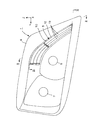
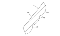
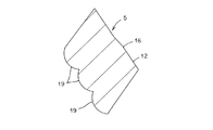
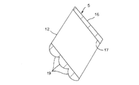
なお、図1においては、ランプハウジングおよびアウターレンズの図示は省略してある。図11(I)は、インナーレンズの正面図、図11(A)は、図11(I)におけるA−A線断面図、図11(A)は、図11(I)におけるA−A線断面図、図11(B)は、図11(I)におけるB−B線断面図、図11(C)は、図11(I)におけるC−C線断面図、図11(D)は、図11(I)におけるD−D線断面図、図11(E)は、図11(I)におけるE−E線断面図である。図12(I)は、インナーレンズを左側斜め下から見た斜視図、図12(F)は、図12(I)におけるF−F線断面図、図12(G)は、図12(I)におけるG−G線断面図、図12(H)は、図12(I)におけるH−H線断面図である。 In FIG. 1, the lamp housing and the outer lens are not shown. 11 (I) is a front view of the inner lens, FIG. 11 (A) is a sectional view taken along line AA in FIG. 11 (I), and FIG. 11 (A) is a line AA in FIG. 11 (I). 11B is a cross-sectional view taken along the line BB in FIG. 11I, FIG. 11C is a cross-sectional view taken along the line CC in FIG. 11I, and FIG. 11D is a cross-sectional view taken along the line DD in FIG. 11I, and FIG. 11E is a cross-sectional view taken along the line EE in FIG. 12 (I) is a perspective view of the inner lens as viewed from diagonally below the left side, FIG. 12 (F) is a cross-sectional view taken along line FF in FIG. 12 (I), and FIG. 12 (G) is FIG. ) Is a cross-sectional view taken along the line GG in FIG. 12, and FIG. 12H is a cross-sectional view taken along the line H-H in FIG.
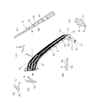
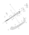
前記車両用灯具1は、図1〜図3に示すように、ランプハウジング2と、アウターレンズ3と、インナーハウジング4と、導光性部材のインナーレンズ5と、半導体型光源6と、すれ違い用ランプユニット7と、走行用ランプユニット8と、を備えるものである。前記車両用灯具1は、車両の前部の右側に装備される右側の車両用灯具であるから、図1において、図の右側(すなわち、前記車両用灯具1の左側)は、車両の前部の中央側であり、図の左側(すなわち、前記車両用灯具1の右側)は、車両の前部の外側である。
As shown in FIGS. 1 to 3, the
前記ランプハウジング2は、たとえば、光不透過性の合成樹脂からなる。前記ランプハウジング2は、図2および図3に示すように、前面側が開口し、その他の5面(後面、上面、下面、左面、右面)側が閉塞した中空形状をなす。なお、図3において、右側の図示は、省略されている。
The
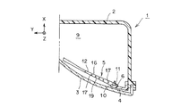
前記アウターレンズ3は、たとえば、光透過性の合成樹脂からなる。前記アウターレンズ3は、図2および図3に示すように、後面側が開口し、その他の5面(前面、上面、下面、左面、右面)側が閉塞した凹形状をなす。前記アウターレンズ3は、素通しのカバーからなる。前記アウターレンズ3は、図2に示すように、側面視(縦断面視、垂直断面視)上下にスラントしている。すなわち、前記アウターレンズ3は、上側が後側に位置しかつ下側が前側に位置するようにスラントしている。また、前記アウターレンズ3は、図3に示すように、平面視(横断面視、水平断面視)左右にスラントしている。すなわち、前記アウターレンズ3は、右側が後側に位置しかつ左側が前側に位置するようにスラントしている。なお、図3において、右側の図示は、省略されている。
The
前記ランプハウジング2の前面開口部の縁と前記アウターレンズ3の後面開口部の縁とが固定されている。前記ランプハウジング2と前記アウターレンズ3とにより灯室9が区画されている。前記灯室9内には、前記インナーハウジング4および前記インナーレンズ5および前記半導体型光源6および前記すれ違い用ランプユニット7および前記走行用ランプユニット8がそれぞれ配置されている。
The edge of the front opening of the
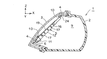
前記インナーハウジング4は、たとえば、光不透過性の合成樹脂からなる。前記インナーハウジング4は、図1〜図3に示すように、中央に開口部10を有する板形状もしくは前記アウターレンズ3に類似した凹形状をなす。前記インナーハウジング4は、前記ランプハウジング2に適宜の取付手段(ボルトナット、スクリュー、加締め、嵌合、接着など)により取り付けられている。前記インナーハウジング4は、前記アウターレンズ3を通して前記車両用灯具1の内部構造が見えないように、前記内部構造を隠して見栄えを向上させるものであって、インナーパネルやエクステンションなどとも呼ばれている。
The
前記インナーレンズ5および前記半導体型光源6は、この例では、信号灯のクリアランスランプのランプユニットを構成する。前記インナーレンズ5は、導光性部材たとえばアクリルからなる。また、前記半導体型光源6は、前記インナーレンズ5の一端に配置されている。
In this example, the
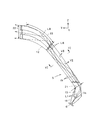
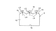
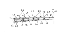
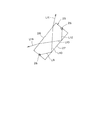
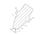
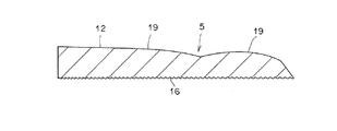
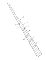
前記インナーレンズ5は、図に示すように、前記半導体型光源6が配置されている一端側のリフレクタ部11と、他端側の発光部12と、から構成されている。前記リフレクタ部11と前記発光部12とは、図5に示すように、正面視鈍角にL字形状に折れ曲がって一体に接続されている。
As shown in the drawing, the
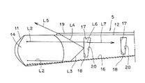
前記リフレクタ部11は、図1〜図3に示すように、前記半導体型光源6と共に前記インナーハウジング4の裏側(前記アウターレンズ3と対向する側と反対側)に配置されている。前記リフレクタ部11は、たとえば、回転放物もしくは回転放物に近似した形状をなす。前記リフレクタ部11の一端(回転放物の頂端)には、半球形の凹部の入射面13が設けられている。前記入射面13は、前記半導体型光源6からの光を前記インナーレンズ5の前記リフレクタ部11の内部に入射させるものである。半球形の凹部の前記入射面13中には、前記半導体型光源6が位置する。
As shown in FIGS. 1 to 3, the
この結果、前記半導体型光源6からの光は、ほとんど全部が前記入射面13から前記リフレクタ部11の内部に入射することができる。すなわち、前記半導体型光源6からの光の指向角(拡散角)が0°軸に対して通常30°〜35°である。そこで、前記リフレクタ部11の形状を、前記半導体型光源6が位置する箇所を頂端として、前記半導体型光源5からの光の指向角を覆う回転放物もしくは回転放物に近似した形状とすることにより、前記半導体型光源6からの光ほとんど全部を前記入射面13から前記リフレクタ部11の内部に入射させることができる。
As a result, almost all of the light from the semiconductor-
前記リフレクタ部11の他端(回転放物の底端)側には、平面の第1内面反射面14が前記リフレクタ部11の回転放物の軸に対して傾斜させて設けられている。前記第1内面反射面14は、前記入射面13から入射した光L1を前記発光部12中に内面反射させるものである。また、前記リフレクタ部11の正面および背面には、平面の補助内面反射面15が相互に平行に設けられている。前記補助内面反射面15は、前記入射光L1のうち、前記リフレクタ部11の正面および背面側に進んだ光を前記第1内面反射面14側に内面反射させるものである。
On the other end (bottom end of the paraboloid) of the
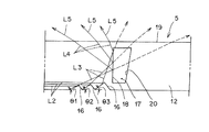
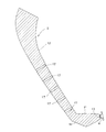
前記発光部12は、図1〜図3に示すように、前記アウターレンズ3の上下左右のスラントに沿って、かつ、前記インナーハウジング4の前記開口部10の左側から上側の一部にかけての縁に沿って配置されている。前記発光部12の裏面(前記アウターレンズ3と対向する面すなわち表面と反対側の面)側には、第2内面反射面16が設けられている。前記第2内面反射面16は、図9および図14および図15に示すように、多数個の2平面プリズムからなり、前記第1内面反射面14からの内面反射光L2を前記発光部12の表面側に内面反射させるものである。
As shown in FIGS. 1 to 3, the light-emitting
前記発光部12の裏面側の前記第2内面反射面16と表面との間には、複数個のスリット17が前記第1内面反射面14からの内面反射光L2の光路に対して交差する方向(直交する方向もしくはほぼ直交する方向)に設けられている。前記スリット17は、前記第1内面反射面14からの内面反射光L2の光路に対して交差する方向の2平面を有する。前記スリット17の前記リフレクタ部11側の平面には、第3内面反射面18が設けられている。前記第3内面反射面18は、前記第2内面反射面16からの内面反射光L3を前記発光部12の表面側に内面反射させるものである。
A direction in which a plurality of
前記発光部12の表面側には、出射面19が設けられている。前記第3内面反射面18からの内面反射光L4を照射光L5として外部に出射させるものである。前記スリット17の前記リフレクタ部11側と反対側の平面には、再入射面20が設けられている。前記再入射面20は、前記第1内面反射面14からの内面反射光L2であって前記第3内面反射面18から屈折して外部すなわち前記スリット17側に出射した光L6を再び内部に入射させるものである。なお、符号L7は、前記再入射面20から前記発光部12の内部に再度入射された光である。
An
図5に示すように、前記発光部12の前記リフレクタ部11との接続部の形状すなわち正面視の幅21は、前記発光部12の前記リフレクタ部11と反対側の端部の形状すなわち正面視の幅22よりも小型すなわち狭い。また、前記発光部12の前記接続部と前記端部との間には、湾曲部23が設けられている。前記湾曲部23は、内面反射により導かれた光L8を発散させるための湾曲部23が設けられている。
As shown in FIG. 5, the shape of the connecting portion of the
前記第2内面反射面16の多数個の2平面プリズムの角度は、図7に示すように、複数の異なる角度θ1、θ2、θ3に設定されている。なお、図7においては、2平面プリズムの角度が3つの異なる角度θ1、θ2、θ3に設定されているが、複数の異なる角度としては、2つもしくは4つ以上でも良い。また、前記出射面19は、図6に示すように、発散系プリズムたとえば3条のシリンドリカルプリズム(凸かまぼこ型のプリズム)からなる。前記第2内面反射面16からの内面反射光L3、すなわち、前記第3内面反射面18からの内面反射光L4の発散方向(図7参照)と、前記出射面19からの出射光L5の発散方向とは、交差すなわち直交もしくはほぼ直交する。
As shown in FIG. 7, the angles of the multiple two-plane prisms of the second inner
前記インナーレンズ5は、取付部24を介して前記インナーハウジング4またはおよび前記ランプハウジング2に取り付けられている。また、前記半導体型光源6は、取付部(図示せず)を介して前記インナーハウジング4またはおよび前記ランプハウジング2に取り付けられている。
The
前記すれ違い用ランプユニット7および前記走行用ランプユニット8は、前記インナーレンズ5および前記半導体型光源6からなる信号灯のクリアランスランプのランプユニットの機能と異なるランプ機能を有する。すなわち、前記すれ違い用ランプユニット7は、すれ違い用配光パターン(図示せず)を車両の前方に照射するものである。また、前記走行用ランプユニット8は、走行用配光パターン(図示せず)を車両の前方に照射するものである。前記すれ違い用ランプユニット7および前記走行用ランプユニット8は、半導体型光源や放電灯やハロゲンバルブなどの光源からなるリフレクタタイプのランプユニットもしくはプロジェクタタイプのランプユニットから構成されている。
The passing
この実施例にかかる車両用灯具1は、以上のごとき構成からなり、以下、その作用について説明する。
The
まず、車両用灯具1の半導体型光源6を点灯発光させる。すると、半導体型光源6から放射された光は、インナーレンズ5の入射面13からインナーレンズ5のリフレクタ部11の内部中に入射する。インナーレンズ5のリフレクタ部11の内部中に入射した光L1は、インナーレンズ5の導光作用により、直接もしくは補助内面反射面15で反射されて第1内面反射面14に進む(図5参照)。
First, the semiconductor type
リフレクタ部11中の第1内面反射面14に進んだ入射光L1は、この第1内面反射面14において発光部12中に内面反射する(図5参照)。この第1内面反射面14からの内面反射光L2は、インナーレンズ5の導光作用により、発光部12中を第2内面反射面16に進む(図7〜図9参照)。
Incident light L1 that has traveled to the first inner
発光部12中の第2内面反射面16に進んだ光(第1内面反射面14からの内面反射光)L2は、この第2内面反射面16において出射面19側に内面反射する(図7〜図9参照)。この第2内面反射面16からの内面反射光L3は、インナーレンズ5の導光作用により、発光部12中を第3内面反射面18に進む(図7〜図9参照)。このとき、第2内面反射面16の2平面プリズムの角度が複数の異なる角度θ1、θ2、θ3に設定されているので、発光部12中の第3内面反射面18に進んだ光(第2内面反射面16からの内面反射光)L3は、発散されている。
The light (inner surface reflected light from the first inner surface reflecting surface 14) L2 that has traveled to the second inner
発散しながら発光部12中の第3内面反射面18に進んだ光L3は、この第3内面反射面18において出射面19側に内面反射する(図7〜図9参照)。この第3内面反射面18からの内面反射光L4は、インナーレンズ5の導光作用により、発光部12中を出射面19に進み、この出射面19から出射光L5として外部に発散しながら出射する(図6〜図9参照)。このとき、第3内面反射面18からの内面反射光L4の発散方向(図7参照)と、出射面19からの出射光L5の発散方向とは、交差するので、出射光L5は、発光部12の出射面19から2方向に発散しながら外部に出射する。
The light L3 that has traveled to the third inner
また、インナーレンズ5の導光作用により、発光部12中を第3内面反射面18に進む第1内面反射面14からの内面反射光L2は、この第3内面反射面18から屈折してから外部(スリット17内)に出射する(図7〜図9参照)。そして、この第3内面反射面18から屈折して外部に出射した光L6は、スリット17の再入射面20から発光部12中に再度入射する(図7〜図9参照)。このとき、再入射面20の補正作用により、第3内面反射面18から屈折して外部に出射した光L6は、第1内面反射面14からの内面反射光L2と平行な光として、再入射面20から発光部12中に再び入射する。このために、再入射面20から発光部12中に再度入射した光L7は、第1内面反射面14からの内面反射光L2と平行である。
Further, the inner surface reflected light L2 from the first inner
再入射面20から発光部12中に再度入射した光L7は、第1内面反射面14からの内面反射光L2と同様に、第2反射面16で内面反射され、かつ、第3反射面18で反射され、出射面19から外部に出射し、または、第3内面反射面18から屈折してから外部に出射する。
The light L7 re-entered into the
半導体型光源6からの光は、インナーレンズ5の導光作用により、リフレクタ部11から発光部12中を発光部12の端部まで内面反射により導かれながら出射面19から外部に発散出射する。内面反射により導かれた光L8は、発光部12の接続部と端部との間の湾曲部23で発散してかつ出射面19から外部に発散出射する。この結果、インナーレンズ5の発光部12の表面の出射面19が全範囲に亘って発光する。これにより、クリアランスランプの機能を果たすことができる。
Light from the semiconductor-
また、すれ違い用ランプユニット7の光源を点灯すると、すれ違い用ランプユニット7からすれ違い用配光パターンが車両の前方に照射される。一方、走行用ランプユニット8の光源を点灯すると、走行用ランプユニット8から走行用配光パターンが車両の前方に照射される。
When the light source of the passing
この実施例にかかる車両用灯具1は、以上のごとき構成および作用からなり、以下、その効果について説明する。
The
この実施例にかかる車両用灯具1は、半導体型光源6からの光ほとんど全部をインナーレンズ5のリフレクタ部11の入射面13から入射させてかつリフレクタ部11の第1内面反射面14で発光部12中に内面反射させることができる。このために、この実施例にかかる車両用灯具1は、半導体型光源6からの光ほとんど全部を発光部12の第2内面反射面16および第3内面反射面18で内面反射させてかつ発光部12の出射面19から外部に出射させることができる。この結果、この実施例にかかる車両用灯具1は、半導体型光源6からの光を高効率に利用することができるので、輝度(光度、照度、光束)が高く、すなわち明るく、視認性もしくは被視認性(以下、単に「視認性」と称する)に優れ、これにより、交通安全に貢献することができる。しかも、この実施例にかかる車両用灯具1は、半導体型光源6からの光を高効率に利用することができるので、使用する半導体型光源6が1個でも、インナーレンズ5の発光部12を十分に明るく発光させることができ、半導体型光源6の個数を低減することができ、その分製造コストを安価にすることができる。
In the
また、この実施例にかかる車両用灯具1は、インナーレンズ5のリフレクタ部11が半導体型光源6と共にインナーハウジング4の裏側に配置されているので、インナーレンズ5のリフレクタ部11および半導体型光源6がインナーハウジング4に隠れていてアウターレンズ3を通して見えず、見栄えが向上される。
Further, in the
さらに、この実施例にかかる車両用灯具1は、インナーレンズ5の発光部12がアウターレンズ5の上下左右のスラントに沿って、かつ、インナーハウジング4の開口部10の左側から上側の一部にかけての縁に沿って配置されている。このために、この実施例にかかる車両用灯具1は、アウターレンズ3が上下左右にスラントしている場合であっても、インナーレンズ5の発光部12がアウターレンズ3のスラントに追従することができ、かつ、インナーレンズ5の発光部12がインナーハウジング4の開口部10の縁に沿うことができるので、車両用灯具の設計の自由度が向上される。その上、この実施例にかかる車両用灯具1は、灯室9内に、インナーレンズ5および半導体型光源6からなるクリアランスランプ以外に、すれ違い用ランプユニット7および走行用ランプユニット8を配置したコンビネーションタイプの車両用灯具であるが、すれ違い用ランプユニット7および走行用ランプユニット8などの他のランプユニットの機能を十分に満足させることができると共に、インナーレンズ5および半導体型光源6からなるクリアランスランプのランプユニットの機能をも十分に満足させることができる。
Furthermore, in the
さらにまた、この実施例にかかる車両用灯具1は、インナーレンズ5の発光部12の第2内面反射面16および第3内面反射面18により、第1内面反射面14からの内面反射光L2を出射面19から出射光L5として、第1内面反射面14からの内面反射光L2の光路に対して鋭角に出射させることができる(図7参照)。このために、この実施例にかかる車両用灯具1は、インナーレンズ5が上下にスラントしている場合(インナーレンズ5が図2に示すように側面視でスラントしている場合)において、半導体型光源6を上下にスラントしているインナーレンズ5の下側に配置することができる。すなわち、この実施例にかかる車両用灯具1は、上下にスラントしているインナーレンズ5の下側に配置されている半導体型光源6からの光であって第1内面反射面14からの内面反射光L2を、発光部12の第2内面反射面16および第3内面反射面18により、出射面19から出射光L5として、第1内面反射面14からの内面反射光L2の光路(下から斜め上に進む光路)に対して鋭角に(前方に)出射させることができる。
Furthermore, the
これにより、この実施例にかかる車両用灯具1は、インナーレンズ5が上下にスラントしている場合において、半導体型光源6を上下にスラントしているインナーレンズ5の下側に配置することができる。これに対して、第3内面反射面18(およびスリット17および再入射面20)が無いインナーレンズの場合には、半導体型光源を、上下にスラントしているインナーレンズの下側に配置することができず、上下にスラントしているインナーレンズの上側にしか配置することができない。以下、その理由について、図10を参照して説明する。
Thereby, the
インナーレンズの導光作用を利用して、半導体型光源からの光をインナーレンズの裏面で内面反射させてインナーレンズの表面から外部に前方に出射させるためには、インナーレンズの裏面の内面反射面の臨界角の要件により、半導体型光源からの光をインナーレンズの裏面の内面反射面に鈍角で入射させる必要がある。このために、図10に示すように、上下にスラントしているインナーレンズ25の場合、半導体型光源26を上下にスラントしているインナーレンズ25の下側に配置する。すると、下側の半導体型光源26からの光L9は、インナーレンズ25の裏面27の内面反射面に鈍角で入射して表面28側に内面反射し、その内面反射光L10は、インナーレンズ25の表面28の出射面から出射光L11として外部に上方に出射する。この出射光L11では、グレアとなる。
In order to reflect the light from the semiconductor-type light source on the back surface of the inner lens and emit it forward from the surface of the inner lens to the outside using the light guide action of the inner lens, the inner surface reflection surface on the back surface of the inner lens Because of this critical angle requirement, light from a semiconductor-type light source must be incident at an obtuse angle on the inner reflective surface of the back surface of the inner lens. For this purpose, as shown in FIG. 10, in the case of the
そこで、図10に示すように、上下にスラントしているインナーレンズ25の場合、半導体型光源26を上下にスラントしているインナーレンズ25の上側に配置する必要がある。半導体型光源26を上下にスラントしているインナーレンズ25の上側に配置する。すると、上側の半導体型光源26からの光L12は、インナーレンズ25の裏面27の内面反射面に鈍角で入射して表面28側に内面反射し、その内面反射光L13は、インナーレンズ25の表面28の出射面から出射光L14として外部に前方に出射する。この出射光L14は、車両の前方を照明することができる。
Therefore, as shown in FIG. 10, in the case of the
このように、上下にスラントしているインナーレンズの場合、半導体型光源を上下にスラントしているインナーレンズの下側に配置することができず上側にしか配置することができない。これに対して、この実施例にかかる車両用灯具1は、インナーレンズ5が上下にスラントしている場合において、半導体型光源6を上下にスラントしているインナーレンズ5の下側に配置することができる。
Thus, in the case of the inner lens slanted up and down, the semiconductor-type light source cannot be arranged below the inner lens slanted up and down, and can only be arranged on the upper side. On the other hand, when the
このために、この実施例にかかる車両用灯具1は、灯室9内に他の機能のランプユニット、たとえば、すれ違い用ランプユニット7および走行用ランプユニット8を配置したコンビネーションタイプの車両用灯具(車両用前照灯)の場合。この場合において、他のランプユニット7および8の光源で発生した熱が上方に行くので、上下にスラントしているインナーレンズ5の下側に配置されている半導体型光源6は、他のランプユニット7および8の光源の熱の影響を受け難く、発光性能を低下させることが無い。また、灯室9の上方は、フードやラジコアアッパーなどの他の部品がレイアウトされているのに対して、灯室9の下方は、他の部品のレイアウトが無く、半導体型光源6の設置スペースが広いので、半導体型光源6の設置設計の自由度が向上される。
For this reason, the
さらにまた、この実施例にかかる車両用灯具1は、インナーレンズ5の発光部12の再入射面20により、第1内面反射面14からの内面反射光L2であって第3内面反射面18から屈折して外部すなわちスリット17側に出射した光L6を再び発光部12の内部に入射させることができる。この結果、この実施例にかかる車両用灯具1は、半導体型光源6からの光の損失を防ぐことができ、半導体型光源6からの光を高効率に利用することができる。その上、この実施例にかかる車両用灯具1は、インナーレンズ5の発光部12のスリット17の第3内面反射面18および再入射面20を複数個設定することにより、インナーレンズ5の発光部12の距離を伸ばすことができるので、インナーレンズ5の発光部12の発光面積を広げることができ、視認性が向上される。
Furthermore, the
さらにまた、この実施例にかかる車両用灯具1は、インナーレンズ5の発光部12のリフレクタ部11との接続部の形状すなわち正面視の幅21がインナーレンズ5の発光部12のリフレクタ部11と反対側の端部の形状すなわち正面視の幅22よりも小型すなわち狭い。このために、この実施例にかかる車両用灯具1は、半導体型光源6からの光であって第1内面反射面14からの内面反射光L2がインナーレンズ5の発光部12中に入射する効率が向上する。すなわち、この実施例にかかる車両用灯具1は、導光体の光入射側の形状が大型であると、半導体型光源からの光が導光体の光入射側に入射する際のロス(光が導光体に入射してもその導光体から抜けていくロス)が大きい。
Furthermore, in the
しかも、この実施例にかかる車両用灯具1は、インナーレンズ5の発光部12のリフレクタ部11との接続部の形状すなわち正面視の幅21が小型すなわち狭くても、インナーレンズ5の発光部12のリフレクタ部11と反対側の端部の形状すなわち正面視の幅22が大型すなわち広いから、インナーレンズ5の発光部12の発光面積を広くすることができ、視認性が向上される。その上、この実施例にかかる車両用灯具1は、インナーレンズ5の発光部12の接続部と端部との間の湾曲部23により、内面反射でインナーレンズ5の発光部12中において導かれた光L8を発散させることができるので、インナーレンズ5の発光部12の発光面積を広くすることができ、視認性が向上される。
Moreover, the
さらにまた、この実施例にかかる車両用灯具1は、インナーレンズ5の発光部12の出射面19から出射する光L5を交差すなわち直交もしくはほぼ直交する2方向に発散させることができるので、インナーレンズ5の発光部12の発光面積をさらに広げることができ、視認性がさらに向上される。
Furthermore, the
なお、前記の実施例においては、インナーレンズ5と半導体型光源6とからなる車両用灯具としてクリアランスランプの信号灯について説明するものである。ところが、この発明においては、車両用灯具として、クリアランスランプの信号灯以外の車両用灯具、たとえば、デイタイムランニングランプ、フロントターンシグナルランプ、リアターンシグナルランプ、サイドマーカーランプ、テールランプ、ストップランプ、ドアミラーなどのアウトサイドミラー装置に内蔵されるサイドターンシグナルランプなどであっても良い。
In the above-described embodiment, a signal lamp of a clearance lamp will be described as a vehicular lamp including the
また、前記の実施例においては、インナーレンズ5および半導体型光源6からなるクリアランスランプと、すれ違い用ランプユニット7および走行用ランプユニット8と、を配置したフロントコンビネーションタイプの自動車用前照灯としての車両用灯具について説明するものである。ところが、この発明においては、インナーレンズ5および半導体型光源6からなるクリアランスランプのみのシングルタイプの車両用灯具でも良い。
Further, in the above-described embodiment, as a front combination type automotive headlamp in which a clearance lamp including the
さらに、前記の実施例においては、使用する半導体型光源6が1個の例について説明するものである。ところが、この発明においては、使用する半導体型光源が複数個でも良い。
Furthermore, in the said Example, the semiconductor type
さらにまた、前記の実施例においては、1個の半導体型光源6と1個のリフレクタ部11とが1ペアの例について説明するものである。ところが、この発明においては、複数個の半導体型光源を1個のリフレクタ部に設けたり、1個の半導体型光源と1個のリフレクタ部とを複数ペア設けたりしても良い。
Furthermore, in the said Example, the one semiconductor type
さらにまた、前記の実施例においては、半導体型光源6をインナーレンズ5の下側に配置した例について説明するものである。ところが、この発明においては、半導体型光源をインナーレンズの上側や左側や右側に配置しても良い。
Furthermore, in the said Example, the example which has arrange | positioned the semiconductor type
さらにまた、前記の実施例においては、アウターレンズ3が上下左右にスラントしている例について説明するものである。ところが、この発明においては、上下にスラントしているアウターレンズ、左右にスラントしているアウターレンズ、スラントしていないアウターレンズでも良い。
Furthermore, in the said Example, the example in which the
さらにまた、前記の実施例においては、第2内面反射面16からの内面反射光L3を第1内面反射面14からの内面反射光L2に対して鋭角に出射させるために、インナーレンズ5の発光部12にスリット17および第3内面反射面18を設けた例について説明するものである。ところが、この発明においては、インナーレンズの発光部にスリットおよび第3内面反射面を設けなくとも良い。この場合、第2内面反射面16からの内面反射光L3が、図7中の破線矢印に示すように、第1内面反射面14からの内面反射光L2に対して鈍角に出射するので、半導体型光源がインナーレンズの下側に位置し、かつ、アウターレンズが上下にスラントする車両用灯具には適さない。
Furthermore, in the above embodiment, the
1 車両用灯具
2 ランプハウジング
3 アウターレンズ
4 インナーハウジング
5 インナーレンズ
6 半導体型光源
7 すれ違い用ランプユニット
8 走行用ランプユニット
9 灯室
10 開口部
11 リフレクタ部
12 発光部
13 入射面
14 第1内面反射面
15 補助内面反射面
16 第2内面反射面
17 スリット
18 第3内面反射面
19 出射面
20 再入射面
21 接続部の幅
22 端部の幅
23 湾曲部
24 取付部
25 アウターレンズ
26 半導体型光源
27 裏面
28 表面
L1 入射面からの入射光
L2 第1内面反射面からの内面反射光
L3 第2内面反射面からの内面反射光
L4 第3内面反射面からの内面反射光
L5 出射面からの出射光
L6 第3内面反射面からの屈折光
L7 再入射面からの再入射光
L8 インナーレンズの発光部中の内面反射光
L9 アウターレンズの下側に配置された半導体型光源からの入射光
L10 アウターレンズの裏面からの内面反射光
L11 アウターレンズの表面面からの出射光
L12 アウターレンズの上側に配置された半導体型光源からの入射光
L13 アウターレンズの裏面からの内面反射光
L14 アウターレンズの表面面からの出射光
DESCRIPTION OF SYMBOLS 1 Vehicle lamp 2 Lamp housing 3 Outer lens 4 Inner housing 5 Inner lens 6 Semiconductor type light source 7 Passing lamp unit 8 Running lamp unit 9 Lamp chamber 10 Opening part 11 Reflector part 12 Light emitting part 13 Incident surface 14 1st inner surface reflection Surface 15 Auxiliary inner reflective surface 16 Second inner reflective surface 17 Slit 18 Third inner reflective surface 19 Outgoing surface 20 Re-incident surface 21 Width of connecting portion 22 Width of end portion 23 Bending portion 24 Mounting portion 25 Outer lens 26 Semiconductor type light source 27 Back surface 28 Front surface L1 Incident light from incident surface L2 Inner surface reflected light from first inner surface reflecting surface L3 Inner surface reflected light from second inner surface reflecting surface L4 Inner surface reflected light from third inner surface reflecting surface L5 Outgoing from exit surface Emission light L6 Refracted light from the third inner reflective surface L7 Re-incident light from the re-incident surface L8 Inner lens Internally reflected light in the light emitting portion L9 Incident light from a semiconductor-type light source disposed below the outer lens L10 Internally reflected light from the back surface of the outer lens L11 Emitted light from the surface surface of the outer lens L12 Above the outer lens Incident light from the disposed semiconductor light source L13 Internally reflected light from the back surface of the outer lens L14 Outgoing light from the surface surface of the outer lens
Claims (5)
導光性部材のインナーレンズと、前記インナーレンズの一端に配置されている前記半導体型光源と、を備え、
前記インナーレンズは、前記半導体型光源が配置されている一端側のリフレクタ部と、他端側の発光部と、から構成されており、
前記リフレクタ部は、前記半導体型光源からの光を内部に入射させる入射面と、前記入射面から入射した光を前記発光部中に内面反射させる第1内面反射面を有し、
前記発光部は、裏面側に設けられていて前記第1内面反射面からの内面反射光を表面側に内面反射させる第2内面反射面と、表面側に設けられていて前記第2内面反射面からの内面反射光を外部に出射させる出射面と、を有する、
ことを特徴とする車両用灯具。 In a vehicle lamp that uses a semiconductor-type light source as a light source,
An inner lens of a light guide member, and the semiconductor-type light source disposed at one end of the inner lens,
The inner lens is composed of a reflector portion on one end side where the semiconductor light source is disposed, and a light emitting portion on the other end side,
The reflector unit includes an incident surface that allows light from the semiconductor-type light source to enter inside, and a first inner surface reflecting surface that internally reflects light incident from the incident surface into the light emitting unit,
The light emitting portion is provided on the back surface side, the second inner surface reflecting surface for reflecting the inner surface reflected light from the first inner surface reflecting surface to the inner surface side, and the second inner surface reflecting surface provided on the front surface side. An emission surface for emitting the inner surface reflected light from the outside,
A vehicular lamp characterized by the above.
灯室を区画するランプハウジングおよびアウターレンズと、
前記灯室内に配置されていて中央に開口部を有するインナーハウジングと、
前記灯室内に配置されている導光性部材のインナーレンズと、
前記灯室内であって前記インナーレンズの一端に配置されている前記半導体型光源と、
を備え、
前記インナーレンズは、前記半導体型光源が配置されている一端側のリフレクタ部と、他端側の発光部と、から構成されており、
前記リフレクタ部は、前記半導体型光源と共に前記インナーハウジングの裏側に配置されていて、前記半導体型光源からの光を内部に入射させる入射面と、前記入射面から入射した光を前記発光部中に内面反射させる第1内面反射面を有し、
前記発光部は、前記アウターレンズに沿ってかつ前記インナーハウジングの開口部の縁に沿って配置されていて、裏面側に設けられていて前記第1内面反射面からの内面反射光を表面側に内面反射させる第2内面反射面と、表面側に設けられていて前記第2内面反射面からの内面反射光を外部に出射させる出射面と、を有する、
ことを特徴とする車両用灯具。 In a vehicle lamp that uses a semiconductor-type light source as a light source,
A lamp housing and an outer lens that partition the lamp chamber;
An inner housing disposed in the lamp chamber and having an opening in the center;
An inner lens of a light guide member disposed in the lamp chamber;
The semiconductor-type light source disposed in one end of the inner lens in the lamp chamber;
With
The inner lens is composed of a reflector portion on one end side where the semiconductor light source is disposed, and a light emitting portion on the other end side,
The reflector unit is disposed on the back side of the inner housing together with the semiconductor-type light source, and an incident surface that allows light from the semiconductor-type light source to enter the inside, and light incident from the incident surface into the light-emitting unit. A first inner reflecting surface for reflecting the inner surface;
The light emitting portion is disposed along the outer lens and along the edge of the opening of the inner housing, and is provided on the back surface side so that the inner surface reflected light from the first inner surface reflecting surface is directed to the front surface side. A second inner surface reflecting surface that reflects the inner surface, and an exit surface that is provided on the surface side and emits the inner surface reflected light from the second inner surface reflecting surface to the outside.
A vehicular lamp characterized by the above.
前記スリットは、前記第2内面反射面からの内面反射光を前記出射面側に内面反射させる第3内面反射面と、前記第1内面反射面からの内面反射光であって前記第3内面反射面から屈折して外部に出射した光を再び内部に入射させる再入射面と、を有する、
ことを特徴とする請求項1または2に記載の車両用灯具。 Between the second inner surface reflecting surface and the emitting surface of the light emitting part, a slit is provided in a direction intersecting the optical path of the inner surface reflected light from the first inner surface reflecting surface,
The slit is a third inner surface reflecting surface that reflects inner surface reflected light from the second inner surface reflecting surface toward the emitting surface side, and inner surface reflected light from the first inner surface reflecting surface, and the third inner surface reflected light. A re-incident surface that re-enters the light refracted from the surface and emitted to the outside,
The vehicular lamp according to claim 1 or 2.
前記発光部の前記接続部と前記端部との間には、内面反射により導かれた光を発散させるための湾曲部が設けられている、
ことを特徴とする請求項1〜3のいずれか1項に記載の車両用灯具。 The shape of the connection portion of the light emitting portion with the reflector portion is smaller than the shape of the end portion of the light emitting portion opposite to the reflector portion,
Between the connection part and the end part of the light emitting part, a curved part for diverging light guided by internal reflection is provided,
The vehicular lamp according to any one of claims 1 to 3.
前記出射面が発散系プリズムからなり、
前記第2内面反射面からの内面反射光の発散方向と前記出射面からの出射光の発散方向とが交差する、
ことを特徴とする請求項1〜4のいずれか1項に記載の車両用灯具。 The second inner reflective surface is composed of a plurality of two-plane prisms, and the angles of the two-plane prisms are set to a plurality of different angles,
The exit surface comprises a divergent prism,
The divergence direction of the inner surface reflection light from the second inner surface reflection surface and the divergence direction of the emission light from the emission surface intersect,
The vehicular lamp according to any one of claims 1 to 4, wherein the vehicular lamp is provided.
Priority Applications (1)
| Application Number | Priority Date | Filing Date | Title |
|---|---|---|---|
| JP2006303071A JP2008123718A (en) | 2006-11-08 | 2006-11-08 | Vehicle lighting |
Applications Claiming Priority (1)
| Application Number | Priority Date | Filing Date | Title |
|---|---|---|---|
| JP2006303071A JP2008123718A (en) | 2006-11-08 | 2006-11-08 | Vehicle lighting |
Publications (1)
| Publication Number | Publication Date |
|---|---|
| JP2008123718A true JP2008123718A (en) | 2008-05-29 |
Family
ID=39508271
Family Applications (1)
| Application Number | Title | Priority Date | Filing Date |
|---|---|---|---|
| JP2006303071A Pending JP2008123718A (en) | 2006-11-08 | 2006-11-08 | Vehicle lighting |
Country Status (1)
| Country | Link |
|---|---|
| JP (1) | JP2008123718A (en) |
Cited By (10)
| Publication number | Priority date | Publication date | Assignee | Title |
|---|---|---|---|---|
| JP2010050009A (en) * | 2008-08-25 | 2010-03-04 | Koito Mfg Co Ltd | Luminaire |
| JP2010052444A (en) * | 2008-08-26 | 2010-03-11 | Mitsuba Corp | Vehicular lamp and door mirror incorporating the vehicular lamp |
| JP2010052443A (en) * | 2008-08-26 | 2010-03-11 | Mitsuba Corp | Vehicular lamp and door mirror incorporating the vehicular lamp |
| JP2010165488A (en) * | 2009-01-14 | 2010-07-29 | Mitsuba Corp | Vehicular lamp |
| JP2010282880A (en) * | 2009-06-05 | 2010-12-16 | Koito Mfg Co Ltd | Vehicle lighting |
| KR101500387B1 (en) * | 2013-09-12 | 2015-03-09 | 기아자동차 주식회사 | Head light module |
| JP2015077911A (en) * | 2013-10-17 | 2015-04-23 | 株式会社小糸製作所 | Vehicle lighting |
| JP2016100256A (en) * | 2014-11-25 | 2016-05-30 | 市光工業株式会社 | Vehicle lamp fitting |
| KR20160076086A (en) * | 2014-12-22 | 2016-06-30 | 에스엘 주식회사 | A lamp apparatus for vehicles |
| DE102014114345B4 (en) | 2014-10-02 | 2025-06-26 | Hyundai Motor Company | Headlight module |
Citations (13)
| Publication number | Priority date | Publication date | Assignee | Title |
|---|---|---|---|---|
| JPS6180504U (en) * | 1984-10-31 | 1986-05-29 | ||
| JPH01161129U (en) * | 1988-04-30 | 1989-11-09 | ||
| JPH0414301U (en) * | 1990-05-28 | 1992-02-05 | ||
| JPH04127902U (en) * | 1991-05-16 | 1992-11-20 | 株式会社小糸製作所 | Vehicle lights |
| JPH0589703A (en) * | 1991-09-30 | 1993-04-09 | Koito Mfg Co Ltd | Vehicle lighting fixture |
| US6097549A (en) * | 1997-08-12 | 2000-08-01 | Breault Research Organization, Inc. | Bireflective lens element |
| JP2002025323A (en) * | 2000-07-04 | 2002-01-25 | Nidec Copal Corp | Light guide plate and surface light emitting device using the same |
| JP2003097910A (en) * | 2001-09-25 | 2003-04-03 | Canon Inc | Linear light source, sheet detection device, and image forming device |
| JP2004001710A (en) * | 2002-04-11 | 2004-01-08 | Iisamu:Kk | Side mirror cover, side mirror body and lamp used for these |
| JP2004039503A (en) * | 2002-07-04 | 2004-02-05 | Koito Mfg Co Ltd | Vehicle lighting |
| JP2005353544A (en) * | 2004-06-14 | 2005-12-22 | Omron Corp | Surface light source device and equipment using the device |
| JP2006059541A (en) * | 2004-08-17 | 2006-03-02 | Ichikoh Ind Ltd | Light guide and LED light source unit including the same |
| JP2006202659A (en) * | 2005-01-24 | 2006-08-03 | Citizen Electronics Co Ltd | Planar light source |
-
2006
- 2006-11-08 JP JP2006303071A patent/JP2008123718A/en active Pending
Patent Citations (13)
| Publication number | Priority date | Publication date | Assignee | Title |
|---|---|---|---|---|
| JPS6180504U (en) * | 1984-10-31 | 1986-05-29 | ||
| JPH01161129U (en) * | 1988-04-30 | 1989-11-09 | ||
| JPH0414301U (en) * | 1990-05-28 | 1992-02-05 | ||
| JPH04127902U (en) * | 1991-05-16 | 1992-11-20 | 株式会社小糸製作所 | Vehicle lights |
| JPH0589703A (en) * | 1991-09-30 | 1993-04-09 | Koito Mfg Co Ltd | Vehicle lighting fixture |
| US6097549A (en) * | 1997-08-12 | 2000-08-01 | Breault Research Organization, Inc. | Bireflective lens element |
| JP2002025323A (en) * | 2000-07-04 | 2002-01-25 | Nidec Copal Corp | Light guide plate and surface light emitting device using the same |
| JP2003097910A (en) * | 2001-09-25 | 2003-04-03 | Canon Inc | Linear light source, sheet detection device, and image forming device |
| JP2004001710A (en) * | 2002-04-11 | 2004-01-08 | Iisamu:Kk | Side mirror cover, side mirror body and lamp used for these |
| JP2004039503A (en) * | 2002-07-04 | 2004-02-05 | Koito Mfg Co Ltd | Vehicle lighting |
| JP2005353544A (en) * | 2004-06-14 | 2005-12-22 | Omron Corp | Surface light source device and equipment using the device |
| JP2006059541A (en) * | 2004-08-17 | 2006-03-02 | Ichikoh Ind Ltd | Light guide and LED light source unit including the same |
| JP2006202659A (en) * | 2005-01-24 | 2006-08-03 | Citizen Electronics Co Ltd | Planar light source |
Cited By (12)
| Publication number | Priority date | Publication date | Assignee | Title |
|---|---|---|---|---|
| JP2010050009A (en) * | 2008-08-25 | 2010-03-04 | Koito Mfg Co Ltd | Luminaire |
| JP2010052444A (en) * | 2008-08-26 | 2010-03-11 | Mitsuba Corp | Vehicular lamp and door mirror incorporating the vehicular lamp |
| JP2010052443A (en) * | 2008-08-26 | 2010-03-11 | Mitsuba Corp | Vehicular lamp and door mirror incorporating the vehicular lamp |
| JP2010165488A (en) * | 2009-01-14 | 2010-07-29 | Mitsuba Corp | Vehicular lamp |
| JP2010282880A (en) * | 2009-06-05 | 2010-12-16 | Koito Mfg Co Ltd | Vehicle lighting |
| KR101500387B1 (en) * | 2013-09-12 | 2015-03-09 | 기아자동차 주식회사 | Head light module |
| US9616803B2 (en) | 2013-09-12 | 2017-04-11 | Hyundai Motor Company | Head light module |
| JP2015077911A (en) * | 2013-10-17 | 2015-04-23 | 株式会社小糸製作所 | Vehicle lighting |
| DE102014114345B4 (en) | 2014-10-02 | 2025-06-26 | Hyundai Motor Company | Headlight module |
| JP2016100256A (en) * | 2014-11-25 | 2016-05-30 | 市光工業株式会社 | Vehicle lamp fitting |
| KR20160076086A (en) * | 2014-12-22 | 2016-06-30 | 에스엘 주식회사 | A lamp apparatus for vehicles |
| KR101666511B1 (en) * | 2014-12-22 | 2016-10-17 | 에스엘 주식회사 | A lamp apparatus for vehicles |
Similar Documents
| Publication | Publication Date | Title |
|---|---|---|
| CN108087838B (en) | Vehicle lamp | |
| EP2143991B1 (en) | Lamp | |
| EP2157363B1 (en) | Optical element for vehicle lamp | |
| US9341336B2 (en) | Vehicle headlamp | |
| US10569706B2 (en) | Overhead console and vehicle-body upper structure | |
| JP2010021001A (en) | Lighting fixture | |
| CN101457892A (en) | Vehicle lamp assembly | |
| CN101666454A (en) | Lighting device for vehicle | |
| JP2018092883A (en) | Vehicular lighting fixture | |
| JP6855404B2 (en) | Vehicle lighting | |
| JP4784570B2 (en) | Vehicle lighting | |
| JP2018098011A (en) | Vehicular headlamp | |
| EP2075500A2 (en) | Vehicle headlamp | |
| EP2187117B1 (en) | Vehicle headlamp | |
| JP2008123718A (en) | Vehicle lighting | |
| JP2013122872A (en) | Illumination lamp fitting for vehicle | |
| JP2006019052A (en) | Vehicle lighting | |
| JP2022053395A (en) | Vehicular lighting fixture | |
| CN108916810B (en) | Light reflector for an optical module of a vehicle lamp, vehicle lamp and motor vehicle | |
| JP4831130B2 (en) | Vehicle lighting | |
| JP4586808B2 (en) | Vehicle lighting | |
| JP2008171723A (en) | Vehicle headlamp lamp unit | |
| CN223826107U (en) | Lighting structure, far and near light module and car light | |
| JP4715866B2 (en) | Vehicle lighting | |
| WO2024140814A1 (en) | Lighting module, lamp device and vehicle |
Legal Events
| Date | Code | Title | Description |
|---|---|---|---|
| A621 | Written request for application examination |
Free format text: JAPANESE INTERMEDIATE CODE: A621 Effective date: 20081104 |
|
| A977 | Report on retrieval |
Free format text: JAPANESE INTERMEDIATE CODE: A971007 Effective date: 20100609 |
|
| A131 | Notification of reasons for refusal |
Free format text: JAPANESE INTERMEDIATE CODE: A131 Effective date: 20100622 |
|
| A02 | Decision of refusal |
Free format text: JAPANESE INTERMEDIATE CODE: A02 Effective date: 20110111 |