US6097549A - Bireflective lens element - Google Patents
Bireflective lens element Download PDFInfo
- Publication number
- US6097549A US6097549A US09/133,178 US13317898A US6097549A US 6097549 A US6097549 A US 6097549A US 13317898 A US13317898 A US 13317898A US 6097549 A US6097549 A US 6097549A
- Authority
- US
- United States
- Prior art keywords
- light
- area
- lens element
- assembly
- set forth
- Prior art date
- Legal status (The legal status is an assumption and is not a legal conclusion. Google has not performed a legal analysis and makes no representation as to the accuracy of the status listed.)
- Expired - Lifetime
Links
Images


Classifications
-
- G—PHYSICS
- G02—OPTICS
- G02B—OPTICAL ELEMENTS, SYSTEMS OR APPARATUS
- G02B6/00—Light guides; Structural details of arrangements comprising light guides and other optical elements, e.g. couplings
- G02B6/0001—Light guides; Structural details of arrangements comprising light guides and other optical elements, e.g. couplings specially adapted for lighting devices or systems
- G02B6/0011—Light guides; Structural details of arrangements comprising light guides and other optical elements, e.g. couplings specially adapted for lighting devices or systems the light guides being planar or of plate-like form
- G02B6/0013—Means for improving the coupling-in of light from the light source into the light guide
- G02B6/0015—Means for improving the coupling-in of light from the light source into the light guide provided on the surface of the light guide or in the bulk of it
- G02B6/002—Means for improving the coupling-in of light from the light source into the light guide provided on the surface of the light guide or in the bulk of it by shaping at least a portion of the light guide, e.g. with collimating, focussing or diverging surfaces
- G02B6/0021—Means for improving the coupling-in of light from the light source into the light guide provided on the surface of the light guide or in the bulk of it by shaping at least a portion of the light guide, e.g. with collimating, focussing or diverging surfaces for housing at least a part of the light source, e.g. by forming holes or recesses
-
- B—PERFORMING OPERATIONS; TRANSPORTING
- B60—VEHICLES IN GENERAL
- B60Q—ARRANGEMENT OF SIGNALLING OR LIGHTING DEVICES, THE MOUNTING OR SUPPORTING THEREOF OR CIRCUITS THEREFOR, FOR VEHICLES IN GENERAL
- B60Q1/00—Arrangement of optical signalling or lighting devices, the mounting or supporting thereof or circuits therefor
- B60Q1/26—Arrangement of optical signalling or lighting devices, the mounting or supporting thereof or circuits therefor the devices being primarily intended to indicate the vehicle, or parts thereof, or to give signals, to other traffic
- B60Q1/30—Arrangement of optical signalling or lighting devices, the mounting or supporting thereof or circuits therefor the devices being primarily intended to indicate the vehicle, or parts thereof, or to give signals, to other traffic for indicating rear of vehicle, e.g. by means of reflecting surfaces
- B60Q1/302—Arrangement of optical signalling or lighting devices, the mounting or supporting thereof or circuits therefor the devices being primarily intended to indicate the vehicle, or parts thereof, or to give signals, to other traffic for indicating rear of vehicle, e.g. by means of reflecting surfaces mounted in the vicinity, e.g. in the middle, of a rear window
-
- F—MECHANICAL ENGINEERING; LIGHTING; HEATING; WEAPONS; BLASTING
- F21—LIGHTING
- F21S—NON-PORTABLE LIGHTING DEVICES; SYSTEMS THEREOF; VEHICLE LIGHTING DEVICES SPECIALLY ADAPTED FOR VEHICLE EXTERIORS
- F21S41/00—Illuminating devices specially adapted for vehicle exteriors, e.g. headlamps
- F21S41/30—Illuminating devices specially adapted for vehicle exteriors, e.g. headlamps characterised by reflectors
- F21S41/32—Optical layout thereof
- F21S41/322—Optical layout thereof the reflector using total internal reflection
-
- F—MECHANICAL ENGINEERING; LIGHTING; HEATING; WEAPONS; BLASTING
- F21—LIGHTING
- F21S—NON-PORTABLE LIGHTING DEVICES; SYSTEMS THEREOF; VEHICLE LIGHTING DEVICES SPECIALLY ADAPTED FOR VEHICLE EXTERIORS
- F21S43/00—Signalling devices specially adapted for vehicle exteriors, e.g. brake lamps, direction indicator lights or reversing lights
- F21S43/10—Signalling devices specially adapted for vehicle exteriors, e.g. brake lamps, direction indicator lights or reversing lights characterised by the light source
- F21S43/13—Signalling devices specially adapted for vehicle exteriors, e.g. brake lamps, direction indicator lights or reversing lights characterised by the light source characterised by the type of light source
- F21S43/14—Light emitting diodes [LED]
-
- F—MECHANICAL ENGINEERING; LIGHTING; HEATING; WEAPONS; BLASTING
- F21—LIGHTING
- F21S—NON-PORTABLE LIGHTING DEVICES; SYSTEMS THEREOF; VEHICLE LIGHTING DEVICES SPECIALLY ADAPTED FOR VEHICLE EXTERIORS
- F21S43/00—Signalling devices specially adapted for vehicle exteriors, e.g. brake lamps, direction indicator lights or reversing lights
- F21S43/20—Signalling devices specially adapted for vehicle exteriors, e.g. brake lamps, direction indicator lights or reversing lights characterised by refractors, transparent cover plates, light guides or filters
- F21S43/235—Light guides
- F21S43/236—Light guides characterised by the shape of the light guide
- F21S43/237—Light guides characterised by the shape of the light guide rod-shaped
-
- F—MECHANICAL ENGINEERING; LIGHTING; HEATING; WEAPONS; BLASTING
- F21—LIGHTING
- F21S—NON-PORTABLE LIGHTING DEVICES; SYSTEMS THEREOF; VEHICLE LIGHTING DEVICES SPECIALLY ADAPTED FOR VEHICLE EXTERIORS
- F21S43/00—Signalling devices specially adapted for vehicle exteriors, e.g. brake lamps, direction indicator lights or reversing lights
- F21S43/20—Signalling devices specially adapted for vehicle exteriors, e.g. brake lamps, direction indicator lights or reversing lights characterised by refractors, transparent cover plates, light guides or filters
- F21S43/235—Light guides
- F21S43/236—Light guides characterised by the shape of the light guide
- F21S43/239—Light guides characterised by the shape of the light guide plate-shaped
-
- F—MECHANICAL ENGINEERING; LIGHTING; HEATING; WEAPONS; BLASTING
- F21—LIGHTING
- F21S—NON-PORTABLE LIGHTING DEVICES; SYSTEMS THEREOF; VEHICLE LIGHTING DEVICES SPECIALLY ADAPTED FOR VEHICLE EXTERIORS
- F21S43/00—Signalling devices specially adapted for vehicle exteriors, e.g. brake lamps, direction indicator lights or reversing lights
- F21S43/20—Signalling devices specially adapted for vehicle exteriors, e.g. brake lamps, direction indicator lights or reversing lights characterised by refractors, transparent cover plates, light guides or filters
- F21S43/235—Light guides
- F21S43/242—Light guides characterised by the emission area
- F21S43/245—Light guides characterised by the emission area emitting light from one or more of its major surfaces
-
- F—MECHANICAL ENGINEERING; LIGHTING; HEATING; WEAPONS; BLASTING
- F21—LIGHTING
- F21S—NON-PORTABLE LIGHTING DEVICES; SYSTEMS THEREOF; VEHICLE LIGHTING DEVICES SPECIALLY ADAPTED FOR VEHICLE EXTERIORS
- F21S43/00—Signalling devices specially adapted for vehicle exteriors, e.g. brake lamps, direction indicator lights or reversing lights
- F21S43/20—Signalling devices specially adapted for vehicle exteriors, e.g. brake lamps, direction indicator lights or reversing lights characterised by refractors, transparent cover plates, light guides or filters
- F21S43/235—Light guides
- F21S43/247—Light guides with a single light source being coupled into the light guide
-
- F—MECHANICAL ENGINEERING; LIGHTING; HEATING; WEAPONS; BLASTING
- F21—LIGHTING
- F21S—NON-PORTABLE LIGHTING DEVICES; SYSTEMS THEREOF; VEHICLE LIGHTING DEVICES SPECIALLY ADAPTED FOR VEHICLE EXTERIORS
- F21S43/00—Signalling devices specially adapted for vehicle exteriors, e.g. brake lamps, direction indicator lights or reversing lights
- F21S43/20—Signalling devices specially adapted for vehicle exteriors, e.g. brake lamps, direction indicator lights or reversing lights characterised by refractors, transparent cover plates, light guides or filters
- F21S43/235—Light guides
- F21S43/249—Light guides with two or more light sources being coupled into the light guide
-
- F—MECHANICAL ENGINEERING; LIGHTING; HEATING; WEAPONS; BLASTING
- F21—LIGHTING
- F21S—NON-PORTABLE LIGHTING DEVICES; SYSTEMS THEREOF; VEHICLE LIGHTING DEVICES SPECIALLY ADAPTED FOR VEHICLE EXTERIORS
- F21S43/00—Signalling devices specially adapted for vehicle exteriors, e.g. brake lamps, direction indicator lights or reversing lights
- F21S43/30—Signalling devices specially adapted for vehicle exteriors, e.g. brake lamps, direction indicator lights or reversing lights characterised by reflectors
- F21S43/31—Optical layout thereof
- F21S43/315—Optical layout thereof using total internal reflection
-
- F—MECHANICAL ENGINEERING; LIGHTING; HEATING; WEAPONS; BLASTING
- F21—LIGHTING
- F21S—NON-PORTABLE LIGHTING DEVICES; SYSTEMS THEREOF; VEHICLE LIGHTING DEVICES SPECIALLY ADAPTED FOR VEHICLE EXTERIORS
- F21S43/00—Signalling devices specially adapted for vehicle exteriors, e.g. brake lamps, direction indicator lights or reversing lights
- F21S43/40—Signalling devices specially adapted for vehicle exteriors, e.g. brake lamps, direction indicator lights or reversing lights characterised by the combination of reflectors and refractors
-
- F—MECHANICAL ENGINEERING; LIGHTING; HEATING; WEAPONS; BLASTING
- F21—LIGHTING
- F21V—FUNCTIONAL FEATURES OR DETAILS OF LIGHTING DEVICES OR SYSTEMS THEREOF; STRUCTURAL COMBINATIONS OF LIGHTING DEVICES WITH OTHER ARTICLES, NOT OTHERWISE PROVIDED FOR
- F21V5/00—Refractors for light sources
- F21V5/008—Combination of two or more successive refractors along an optical axis
-
- F—MECHANICAL ENGINEERING; LIGHTING; HEATING; WEAPONS; BLASTING
- F21—LIGHTING
- F21V—FUNCTIONAL FEATURES OR DETAILS OF LIGHTING DEVICES OR SYSTEMS THEREOF; STRUCTURAL COMBINATIONS OF LIGHTING DEVICES WITH OTHER ARTICLES, NOT OTHERWISE PROVIDED FOR
- F21V5/00—Refractors for light sources
- F21V5/04—Refractors for light sources of lens shape
-
- F—MECHANICAL ENGINEERING; LIGHTING; HEATING; WEAPONS; BLASTING
- F21—LIGHTING
- F21V—FUNCTIONAL FEATURES OR DETAILS OF LIGHTING DEVICES OR SYSTEMS THEREOF; STRUCTURAL COMBINATIONS OF LIGHTING DEVICES WITH OTHER ARTICLES, NOT OTHERWISE PROVIDED FOR
- F21V7/00—Reflectors for light sources
- F21V7/0091—Reflectors for light sources using total internal reflection
-
- G—PHYSICS
- G02—OPTICS
- G02B—OPTICAL ELEMENTS, SYSTEMS OR APPARATUS
- G02B19/00—Condensers, e.g. light collectors or similar non-imaging optics
- G02B19/0004—Condensers, e.g. light collectors or similar non-imaging optics characterised by the optical means employed
- G02B19/0028—Condensers, e.g. light collectors or similar non-imaging optics characterised by the optical means employed refractive and reflective surfaces, e.g. non-imaging catadioptric systems
-
- G—PHYSICS
- G02—OPTICS
- G02B—OPTICAL ELEMENTS, SYSTEMS OR APPARATUS
- G02B19/00—Condensers, e.g. light collectors or similar non-imaging optics
- G02B19/0033—Condensers, e.g. light collectors or similar non-imaging optics characterised by the use
- G02B19/0047—Condensers, e.g. light collectors or similar non-imaging optics characterised by the use for use with a light source
- G02B19/0061—Condensers, e.g. light collectors or similar non-imaging optics characterised by the use for use with a light source the light source comprising a LED
-
- G—PHYSICS
- G02—OPTICS
- G02B—OPTICAL ELEMENTS, SYSTEMS OR APPARATUS
- G02B3/00—Simple or compound lenses
- G02B3/02—Simple or compound lenses with non-spherical faces
- G02B3/08—Simple or compound lenses with non-spherical faces with discontinuous faces, e.g. Fresnel lens
-
- G—PHYSICS
- G02—OPTICS
- G02B—OPTICAL ELEMENTS, SYSTEMS OR APPARATUS
- G02B6/00—Light guides; Structural details of arrangements comprising light guides and other optical elements, e.g. couplings
- G02B6/0001—Light guides; Structural details of arrangements comprising light guides and other optical elements, e.g. couplings specially adapted for lighting devices or systems
- G02B6/0011—Light guides; Structural details of arrangements comprising light guides and other optical elements, e.g. couplings specially adapted for lighting devices or systems the light guides being planar or of plate-like form
- G02B6/0013—Means for improving the coupling-in of light from the light source into the light guide
- G02B6/0023—Means for improving the coupling-in of light from the light source into the light guide provided by one optical element, or plurality thereof, placed between the light guide and the light source, or around the light source
-
- F—MECHANICAL ENGINEERING; LIGHTING; HEATING; WEAPONS; BLASTING
- F21—LIGHTING
- F21Y—INDEXING SCHEME ASSOCIATED WITH SUBCLASSES F21K, F21L, F21S and F21V, RELATING TO THE FORM OR THE KIND OF THE LIGHT SOURCES OR OF THE COLOUR OF THE LIGHT EMITTED
- F21Y2115/00—Light-generating elements of semiconductor light sources
- F21Y2115/10—Light-emitting diodes [LED]
-
- G—PHYSICS
- G02—OPTICS
- G02B—OPTICAL ELEMENTS, SYSTEMS OR APPARATUS
- G02B6/00—Light guides; Structural details of arrangements comprising light guides and other optical elements, e.g. couplings
- G02B6/0001—Light guides; Structural details of arrangements comprising light guides and other optical elements, e.g. couplings specially adapted for lighting devices or systems
- G02B6/0011—Light guides; Structural details of arrangements comprising light guides and other optical elements, e.g. couplings specially adapted for lighting devices or systems the light guides being planar or of plate-like form
- G02B6/0033—Means for improving the coupling-out of light from the light guide
- G02B6/0035—Means for improving the coupling-out of light from the light guide provided on the surface of the light guide or in the bulk of it
- G02B6/0038—Linear indentations or grooves, e.g. arc-shaped grooves or meandering grooves, extending over the full length or width of the light guide
-
- G—PHYSICS
- G02—OPTICS
- G02B—OPTICAL ELEMENTS, SYSTEMS OR APPARATUS
- G02B6/00—Light guides; Structural details of arrangements comprising light guides and other optical elements, e.g. couplings
- G02B6/0001—Light guides; Structural details of arrangements comprising light guides and other optical elements, e.g. couplings specially adapted for lighting devices or systems
- G02B6/0011—Light guides; Structural details of arrangements comprising light guides and other optical elements, e.g. couplings specially adapted for lighting devices or systems the light guides being planar or of plate-like form
- G02B6/0033—Means for improving the coupling-out of light from the light guide
- G02B6/0035—Means for improving the coupling-out of light from the light guide provided on the surface of the light guide or in the bulk of it
- G02B6/0045—Means for improving the coupling-out of light from the light guide provided on the surface of the light guide or in the bulk of it by shaping at least a portion of the light guide
- G02B6/0046—Tapered light guide, e.g. wedge-shaped light guide
- G02B6/0048—Tapered light guide, e.g. wedge-shaped light guide with stepwise taper
Definitions
- the subject invention relates to a thin light emitting assembly, and more particularly, to a thin bireflective lens which achieves efficient and uniform surface illumination with only a single light source and the lens element.
- Conventional light emitting assemblies for automotive vehicle headlights, sidelights and taillights typically include a bulb filament recessed in a reflector housing behind a cover lens.
- the light emitted from the bulb filament is reflected from the reflector housing outwardly through the cover lens to form a beam or planar light image.
- the cover lens shapes the light into the desired pattern, i.e. focused headlight beam or pattern side or rear signal.
- conventional bulb and reflector lighting systems are disadvantageous in terms of styling and size flexibility.
- the bulb and reflector require a significant depth and width to acquire desired focus and light dispersion through the cover lens, thus, limiting the ability to streamline and contour the light system.
- the Jiao et al. '792 patent has a number of deficiencies.
- One such deficiency is the lighting design creates a "black" area or shadow in the middle of the lens. This is created because light is not permitted to travel through a deflector which is mounted to the center of the assembly.
- Other deficiencies are that the design is not rotationally symmetric, and not easily compatible with a light emitting diode.
- the subject invention is a bireflective lens element comprising a light input surface and a direct transmitting area communicating with the light input surface.
- a first portion of input light is directed through the lens elements in a first predetermined pattern.
- a primary and a secondary reflecting area is between the light input surface and an illumination surface surrounding the direct light transmitting area.
- a second portion of input light is redirected through the lens element to the illumination surface in a second predetermined pattern.
- the subject invention also incorporates a light source adjacent to the light input surface for projecting light into the lens element which creates a light emitting assembly.
- the subject invention includes the secondary reflective area having a plurality of extracting facets extending inwardly into the secondary reflective area for intercepting light from the primary reflective area.
- the facets each include a substantially parabolic surface for redirecting light from the primary reflective area outwardly away from the bireflective lens element to the illumination surface.
- the subject invention incorporates the advantages of a thin light emitting assembly while eliminating any "black" area or shadow within the lens. Further the subject invention incorporates a novel design for the facets to assist in redirecting the light from a light source toward the illumination surface.
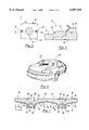
- FIG. 1 is a plan view of a bireflective lens element according to the present invention showing a central primary reflective area and eight discreet secondary reflective areas surrounding the central primary reflective area as well as virtual portions of the secondary reflective areas shown in phantom lines;
- FIG. 2 is a cross-section of the lens element of FIG. 1 taken through the line 2--2 with a cross-section of a pillow lens added as an enhancement to the bireflective lens element of the present invention
- FIG. 3 is an enlarged view of the area within the circle 3 in FIG. 2;
- FIG. 4 is a cross-sectional view in the direction indicated by line 4--4 in FIG. 2 showing a light emitting diode structure and mounting posts of the bireflective lens element according to the present invention
- FIG. 5 is an exploded view of an alternative embodiment of the facets
- FIG. 6 is a partial perspective view of a rear window of a motor vehicle with a center high mounted stop lamp incorporating bireflective lens elements according the present invention
- FIG. 7 is a longitudinal cross-section of a dual bireflective lens element optic structure
- FIG. 8 is a transverse cross sectional view of a bireflective lens element according to the present invention in conjunction with a light spreading pillow lens showing the bireflective lens element tilted slightly with respect to the pillow lens;
- FIG. 9 is a perspective view of an alternative embodiment of the bireflective lens element according to the present invention.
- FIG. 10 is a side view of the alternative embodiment of FIG. 9;
- FIG. 11 is a longitudinal cross-section of another alternate embodiment of the bireflective lens element according to the present invention.
- FIG. 12 is a longitudinal cross-section of yet another alternate embodiment of the bireflective lens element according to the present invention.
- FIG. 13 is a longitudinal cross-section of another alternate embodiment of the bireflective lens element according to the present invention.
- a bireflective lens element according to the present invention is generally designated by reference number 10 in FIGS. 1 and 2.
- Lens element 10 includes a light input surface 12, a primary reflective area 14, preferably having a direct light transmitting area 16 centrally located therein, a secondary reflective area 18 surrounding primary reflective area 14, an illumination, or output, surface 20, and edges 22, 24, 26, and 28.
- the bireflective lens element of the present invention is preferably molded of an optic quality plastic, such as acrylic/PMMA or a polycarbonate.
- lens element 10 The function of lens element 10 is to take light emitted from a single light source, such as a light emitting diode ("LED") structure generally indicated at 30, and redirect the light so that the light is emitted from the illumination surface 20 in a direction substantially normal to the surface 20. Specifically, a first portion of input light passes through the direct light transmitting area 16 of the lens element 10 in a first predetermined pattern. A second portion of input light is redirected through the lens element 10 to the illumination surface 20 in a second predetermined pattern. More specifically, the second portion of input light is emitted through the light input surface to the primary reflection area which redirects the input light toward the secondary reflective area. The input light is then redirected again from the secondary reflective area toward the illumination surface. The first predetermined pattern combines with the second predetermined pattern to output light in a substantially uniform or desired pattern.
- a single light source such as a light emitting diode (“LED") structure generally indicated at 30, and redirect the light so that the light is emitted from the illumination surface 20 in a direction
- This surface illumination may be accomplished by an ultra thin lens element.
- Angular spreading of the light emitted from surface 20 may be accomplished by another optical element, such as an array of pillow lenses, designated generally by reference number 32 as shown in FIG. 2 and further described hereinbelow.
- the light source 30 is shown as a conventional LED structure, which includes an LED 34 and associated electrical leads (not shown) encapsulated in an epoxy body structure which comprises base portion 36 and domed portion 38.
- the domed portion 38 may be tailored so as to achieve specific output characteristics.
- the LED or LED's may be mounted on a carrier (not shown) that provides support and mounting structure for the LED (s) and may also include circuitry for powering and controlling the LED(s).
- the primary reflective area 14 comprises a primary reflective surface 40, preferably in the form of a revolved curved or generally parabolic surface
- secondary reflective area 18 comprises a plurality of extracting facets 42 and adjacent step downs 44. More specifically, the secondary reflective area 18 includes a plurality of facets 42 extending inwardly into the second reflective area 18 for intercepting light from the primary reflective area 14 and redirecting the light toward the illumination surface 20.
- the lens element 10 takes light from the light source 30 which enters through the input surface 12 on the back side of the element 10 and reflects the light by total internal reflection off the primary reflective surface 40 toward the plurality of extracting facets 42 of the secondary reflective area 18.
- the primary reflective surface 40 redirects light in a direction that is radially outward and generally parallel to the output surface 20. From the extracting facets 42, the light is again reflected by total internal reflection toward the illumination surface 20 of the element 10.
- the twice-reflected light which is emitted from the illumination surface 20 is thus substantially collimated.
- the primary reflective area 14 preferably includes a peripheral step down 46 extending about the perimeter of the revolved primary reflective surface 40.
- This step down 46 may be formed with a small draft angle to facilitate molding.
- the extracting facets 42 can be formed by multiple sets of 45° facets and associated step downs 44 that are revolved about a common axis extending through the center of the primary reflective area 14.
- the common axis about which the facets 42 and step downs 44 are revolved is the optical axis of the lens element 10.
- the facets 42 can be designed with the step downs 44 tilted slightly away from normal "N" by a draft angle ⁇ .
- the draft angle ⁇ provides relief to facilitate removal of the element from a mold and may be of almost any value although it is presently contemplated to employ a draft angle a of about 5°.
- the step downs interconnect a trailing edge of a facet to a leading edge of an adjoining facet.
- the step downs 44 are sized and oriented so that the faceted profile starts from an-outside edge of the flat portion of the input surface 12 and would extend to the illumination surface 30 had the element 10 not been truncated at edges 24 and 28.
- This design feature is shown in FIG. 2 in phantom as a "virtual" secondary reflective area having extracting facets 42' and associated step downs 44' which extend to the virtual illumination surface 20'.
- the step downs 44 and 44' and facets 42 and 42' are oriented along a linear base profile.
- Curved base profiles such as concave or convex profiles, however, can also be used.
- the output of the lens 10 will be defined by illumination surface 20 with a dark circular portion in the middle thereof due to the shadow cast by primary reflective area 14.
- direct transmitting area 16 be provided at the center of the primary reflective area 14. As shown by the arrow generally designated by reference letter "B", light transmitted from the light source 30 which enters through the input surface 12 and contacts the direct transmitting area 16 is transmitted directly through the lens element 10, thus providing illumination in the shadow region of the primary reflective area 14 and providing a substantially uniform or broad area of illumination of the lens element 10.
- Direct transmitting area 16 is preferably a flat area defining the base of the primary reflective surface 40 but may comprise a hole formed through the center of the primary reflective area 14 or some type of directly transmitting lens structure, such as a concave, convex, or fresnel lens.
- the lens structure collimates light directly through the lens element.
- the secondary reflective area 18 may be defined by a set of extracting facets 42 and associated facet step downs 44 revolved 360° about the primary reflective area 14, and the shape of the lens element 10 may be rectangular of any aspect ratio, square, round, or some other shape.
- the shape of the element 10 is rectangular with the longer dimension defining a longitudinal direction and the shorter dimension defining a transverse direction.
- the extracting facets are divided into discreet pie-shaped regions, or sectors, each of which comprises a truncated revolved arc.
- discreet sectors progressing clockwise in FIG. 1 from the far right, 48, 50, 52, 54, 56, 58, 60, and 62, are provided as farther described below.
- the element 10 shown in FIG. 1 has a right side secondary reflective area 48.
- virtual right side reflective area 48' is shown in phantom to show the extent to which reflective area 48 would extend if the facet profile were permitted to extend from the input surface 12 out to the virtual illumination surface 20' (see FIG. 2).
- Virtual illumination surface 20' is a virtual extension of actual illumination surface 20.
- a left side secondary reflective area is generally designated by reference number 56 and the associated virtual left side reflective area is shown in phantom and generally designated by reference number 56'.
- Upper secondary reflective area and the associated virtual upper secondary reflective area are designated by reference numbers 60 and 60', respectively.
- Lower secondary reflective area and the associated virtual lower secondary reflective area are generally designated by reference numbers 52 and 52', respectively.
- the upper right secondary reflective area and the associated virtual upper right secondary reflective area are generally designated by reference numbers 62 and 62', respectively.
- the lower right secondary reflective area and the associated virtual lower right secondary reflective area are generally designated by reference numbers 50 and 50', respectively.
- the upper left secondary reflective area and the associated virtual upper left secondary reflective area are generally designated by reference numbers 58 and 58', respectively.
- the lower left secondary reflective area and the associated virtual lower left secondary reflective area are generally designated by reference numbers 54 and 54', respectively.
- the associated virtual reflective area represents the extent to which that reflective area would extend radially outwardly to the virtual illumination surface 20' if the facet profile were not truncated at an edge of the lens element 10.
- the lens element 10 is preferably symmetrical about vertical and horizontal axes extending through its center. That is, right side secondary reflective area 48 is a mirror image of left side secondary reflective area 56, upper secondary reflective area 60 is a mirror image of lower secondary reflective area 52, and the upper right 62, lower right 50, upper left 58, and lower left 54 secondary reflective areas are all mirror images of one another.
- right virtual secondary reflective area 48' extends further radially outwardly then upper right and lower right virtual secondary reflective areas 62' and 50', respectively, which extend further radially outwardly than upper and lower virtual secondary reflective areas 60' and 52', respectively.
- the slope of the facet profile of the upper and lower secondary reflective areas 60 and 52, respectively is steeper than that of the remaining secondary reflective areas, and the slope of the facet profile of the upper right, lower right, upper left, and lower left secondary reflective areas, 62, 50, 58, and 54, respectively, is steeper than the slope of the facet profile of the left and right secondary reflective areas 56 and 48, respectively, but is shallower than the facet profile slope of the upper and lower secondary reflective areas 60 and 52, respectively.
- the profile of the secondary reflecting area is changed by varying the length of individual step downs 44, although the length of individual facets 42 may also be varied if desired.
- the uniformity of the surface illumination from the illumination surface 20 is dependent upon the input light being symmetrically directed about the primary reflective surface 40. Accordingly, it is preferred that the light source 30 be disposed at the horizontal and vertical center of the primary reflective area 14, (i.e., on the optic axis of lens element 10) as an off center position can result in a portion of the primary reflective surface 40 being shaded by other areas of the primary reflective surface 40.
- lens element 10 preferably includes mounting posts 64, 66 for aligning and positioning the lens element 10 with respect to the light source 30.
- LED structures such as those preferably used in conjunction with the present invention, typically include indents 68 and 70 formed in the base portion 36 of the LED structure 30. (see FIGS. 2 and 4).
- Mounting posts 64, 66 extend from opposite sides of the input surface 12 from positions equidistant from the center thereof and are transversely centered with respect to the element 10. Posts 64 and 66 are spaced by a distance corresponding to the distance between inner-most portions of indents 68 and 70.
- the lens element 10 and light source 30 are coupled with one another by inserting posts 64 and 66 into indents 68 and 70, respectively.
- Posts 64 and 66 are positioned and oriented so as to place the domed portion 38 in a centered position with respect to the primary reflective area 14 of the element 10. In other words, inserting the posts 64 and 66 into the indents 68 and 70 ensures that the LED structure 30 will be positioned on the optical axis of the bireflective lens element 10.
- a dual element optic structure is generally designated by reference number 80 in FIG. 7.
- Optic structure 80 includes a right bireflective lens element 82 and a left bireflective lens element 84.
- Right bireflective lens element 82 includes a primary reflective area 86 having an associated primary reflective surface 88 and a direct transmitting area 90, a secondary reflective area 92 having a plurality of extracting facets 94 and associated step downs 96, and an input surface 98 with an associated light source 100 coupled with element 82 by mounting posts 102 and 104.
- left bireflective lens element 84 includes a primary reflective area 106 having an associated primary reflective surface 108 and a direct transmitting surface 110, a secondary reflective area 112 having a plurality of extracting facets 114 and associated step downs 116, and an input surface 118 with an associated light source 120 coupled with element 84 by mounting posts 122 and 124.
- Right bireflective lens element 82 and left bireflective lens element 84 are joined together at a transition area 126 and define a common illumination surface 128.
- the left and right bireflective lens elements 82 and 84 could, however, be oriented such that their respective illumination surfaces are not coplanar with one another.
- the bireflective lens element 10 of the present invention may be advantageously used in many applications in which surface illumination is required from a relatively thin profile optic structure.
- a bireflective lens element coupled with a light source constitutes an example of the unit cell optics design approach whereby one or more optics structures and associated light sources (i.e., one or more unit cells) are constructed and arranged to accommodate lighting design requirements and/or packaging restrictions.
- the unit cell design approach is described in more detail in commonly owned U.S. patent application filed on Aug. 7, 1998 and entitled "Thin Light Managing System For Directing and Distributing Light From One or More Light Sources and Method For Making Optics Structures For Use in the System" the disclosure of which is hereby incorporated by reference.
- a bireflective lens element may be used in various automotive signal lamp applications, for example, a center high mounted stop lamp ("CHMSL") or a rear combination lamp.
- CHMSL center high mounted stop lamp
- FIG. 6 a motor vehicle 130 has a CHMSL 132 mounted in the rear window 134.
- the CHMSL shown incorporates twelve rectangular bireflective lens elements 10 with associated light sources (not shown) to effect an illumination signal lamp surface.
- CHMSL 132 is shown mounted inside the rear window 134 on the back seat shelf.
- a CHMSL may, however, be mounted at a variety of locations on a vehicle, for example on the rear deck lid of the vehicle or on the roof of the vehicle. Bireflective lens elements may be incorporated into a CHMSL wherever it is mounted.
- CHMSL 132 is shown with two rows of six lens element 10 stacked one above the other.
- more or less than twelve lens element/light source combinations may be used in the CHMSL.
- the individual lens element/light source combinations may be arranged in different ways.
- the CHMSL may comprise a single row of lens element/light source combinations, or it may comprise more than two rows of lens element/light source combinations.
- the bireflective lens element 10 may be coupled with light dispensing projections 32 positioned adjacent the illumination surface 20 for assisting in dispersing and redirecting the second portion of input light out of and/or back into the bireflective lens element 10 (see FIGS. 2,8, and 12).
- the light dispersing projections 32 comprise a pillow lens element 32 having an array of pillows 136 formed on a input surface thereof.
- Federal traffic safety regulations require that a CHMSL be visible at points 10° left and right of the lamp and 10° above and 5° below the lamp. Accordingly, the pillow lenses 32 are specifically tailored to spread the light over this test point range.
- light dispersing projections 32 may include an array of prisms and/or other geometrical shapes. In fact, the light dispersing projections 32 may be of any suitable shape or size so long as a sufficient amount of light is dispersed evenly out through the illumination surface 20 and/or redirected back into the lens element 10.
- the pillow lens 32 may be tailored by varying the size of the individual pillows of the array of pillows 136 and by varying the vertical and horizontal radii of curvature of the individual pillows. Relatively small pillow lens optics are preferred as they will break up the partially collimated image of the bireflective lens element most effectively.
- the pillows are 2 mm square and have radii of curvature of 3.8 mm vertically and 2.4 mm horizontally.
- the parabolic equation for the surface of a pillow lens is as follows:
- the bireflective lens element 10 may be tilted upwardly at an angle " ⁇ " of approximately 2.2° with respect to pillow lens array 32.
- the bireflective and/or pillow, or other, lens elements can be similarly tailored to meet other desired light pattern designs or regional visibility requirements as well.
- FIGS. 9 through 13 Variations of the basic bireflective lens element of FIG. 2 are shown in FIGS. 9 through 13.
- FIGS. 9 and 10 disclose an alternative bireflective lens 10 having the flat planar surfaces 43 disposed between the facets 42 of the preferred embodiment.
- the primary reflective area 14 has a cone shaped surface 41 extending from the flat base area of the direct transmitting area 16 to the illumination surface 20.
- the secondary reflective areas 18 are angled slightly inward to form a concave lens element 10.
- a lens structure 74 such as a fresnel lens, is formed onto the input surface 12 for collimating light directly through the lens element 10.
- an alternative arrangement of facets are shown preferably including a reflective surface defining a compound curve for redirecting the light toward the illumination surface 20.
- the facets are spaced apart by adjacent flat planar surfaces 43.
- the extracting facets 42 and step downs 44 are shown in the preferred embodiment of FIGS. 2 and 3 as being flat and uniformly sized and spaced throughout the facet profile. The size, shape, and orientation of the facets and/or step downs may be varied to tailor the output light in accordance with particular illumination requirements. Reflectivity of the reflective surface 40 and facets 42 may also be enhanced by a reflective coating, such as vacuum deposited aluminum.
- lens element 140 includes a primary reflective area 142 with a primary reflective surface 144 that is not a revolved curved or generally parabolic shaped surface but is in the form of a straight cone of angle ⁇ , for example 45°.
- the input surface 146 of element 140 is not a flat surface but is formed as a light conditioning optics surface, in the illustrated embodiment, a Fresnel surface.
- lens element 150 includes an output surface 152 that is not flat, but includes an array of pillows 154 formed integrally with the element 150.
- lens element 160 has a primary reflective area 162 which includes a plurality of primary reflective surfaces 164 to constitute revolved curved, or generally parabolic, shaped surfaces, separated by circumferential facets 166.
- the embodiment of FIG. 13 is another means by which light may be provided within the shadow cast by the primary reflective area 162.
- Light from a light source enters element 160 through input surface 168. A portion of the light is reflected by total internal reflection from the primary reflective surfaces 164 toward the extracting facets 170 of the secondary reflective area 172. Another portion of the input light is transmitted directly through the direct transmission area 174 and the facets 166 of the primary reflective area 162 toward the illumination surface 176.
- Facets 166 are preferably substantially parallel to illumination surface 176 but may have an angled orientation to direct the light transmitted through the facet or a curved shape to spread or focus the light transmitted through the facet.
- primary reflective surfaces 164 may be conical surfaces instead of curved surfaces.
- the thin bireflective lens element of the present invention provides a number of advantages in addition to its ultra thin profile and design flexibility.
- the bireflective lens element achieves surface illumination efficiently, that is with a limited number of light sources.
- Conventional attempts to increase the efficiency of a lighting system typically have involved secondary optical treatments, or components, such as reflective cones for capturing and focusing light from a light source. Providing such secondary treatment can increase cost and complexity due to the additional components and manufacturing steps required.
- the bireflective lens element achieves efficient and uniform surface illumination over a broad area with only a single point light source and the lens element. Therefore, efficiency is improved while eliminating secondary optical treatments from the lighting system.
- the surface behind the lens elements may be visible through the illumination surface of the lens element when the light source is off.
- the ability to see through the lens element when the light source is off is beneficial in some styling scenarios where it is desirable to minimize the visibility of a light system employing bireflective lens elements when the light sources are off.
- a colored background behind the lens elements that is the same color as the structure surrounding the lighting system, it is possible to have the lighting system blend in with its surroundings when the light sources are off.
Abstract
Description
x=y.sup.2 /4.8 +z.sup.2 7.6,
Claims (32)
Priority Applications (1)
| Application Number | Priority Date | Filing Date | Title |
|---|---|---|---|
| US09/133,178 US6097549A (en) | 1997-08-12 | 1998-08-12 | Bireflective lens element |
Applications Claiming Priority (2)
| Application Number | Priority Date | Filing Date | Title |
|---|---|---|---|
| US5524097P | 1997-08-12 | 1997-08-12 | |
| US09/133,178 US6097549A (en) | 1997-08-12 | 1998-08-12 | Bireflective lens element |
Publications (1)
| Publication Number | Publication Date |
|---|---|
| US6097549A true US6097549A (en) | 2000-08-01 |
Family
ID=21996601
Family Applications (1)
| Application Number | Title | Priority Date | Filing Date |
|---|---|---|---|
| US09/133,178 Expired - Lifetime US6097549A (en) | 1997-08-12 | 1998-08-12 | Bireflective lens element |
Country Status (10)
| Country | Link |
|---|---|
| US (1) | US6097549A (en) |
| EP (1) | EP1005619B1 (en) |
| AT (1) | ATE209315T1 (en) |
| AU (1) | AU8796098A (en) |
| BR (1) | BR9811170A (en) |
| CA (1) | CA2299543C (en) |
| DE (1) | DE69803297T2 (en) |
| ES (1) | ES2168784T3 (en) |
| PT (1) | PT1005619E (en) |
| WO (1) | WO1999009349A1 (en) |
Cited By (192)
| Publication number | Priority date | Publication date | Assignee | Title |
|---|---|---|---|---|
| US6250777B1 (en) * | 1998-09-18 | 2001-06-26 | Stanley Electric Co., Ltd. | Double-focus lens and vehicle lamp |
| US6368159B1 (en) * | 2000-12-13 | 2002-04-09 | Stewart Connector Systems, Inc. | Light pipe for a modular jack |
| US6447155B2 (en) | 2000-02-18 | 2002-09-10 | Stanley Electric Co., Ltd. | Double-stacked type lamp unit for the vehicle |
| US6469622B1 (en) * | 1997-12-11 | 2002-10-22 | Stanley Electric Co., Ltd. | Automobile rear combination lamp |
| EP1277615A1 (en) * | 2001-07-19 | 2003-01-22 | Ichikoh Industries, Ltd. | Stop lamp for vehicles |
| FR2833688A1 (en) * | 2001-12-18 | 2003-06-20 | Automotive Lighting Reutlingen | Signal light for automotive vehicle, has an arrangement which deviates light with minimal losses |
| US20030189832A1 (en) * | 2000-05-08 | 2003-10-09 | Alexander Rizkin | Light module |
| FR2841966A1 (en) * | 2002-07-04 | 2004-01-09 | Koito Mfg Co Ltd | VEHICLE LAMP WITH LOW DEPTH REFLECTOR |
| US6700712B2 (en) | 2001-11-13 | 2004-03-02 | 3M Innovative Properties Company | Multidirectional single surface optically shaped film |
| US20040057244A1 (en) * | 2002-07-10 | 2004-03-25 | Koito Manufacturing Co., Ltd. | Vehicle lamp |
| US20040070989A1 (en) * | 2002-07-04 | 2004-04-15 | Koito Manufacturing Co., Ltd. | Vehicle lamp |
| US20040075575A1 (en) * | 1998-11-06 | 2004-04-22 | Demarco Ralph Anthony | Recognition/anti-collision light for aircraft |
| US20040156209A1 (en) * | 2003-02-10 | 2004-08-12 | Hiroyuki Ishida | Vehicular headlamp and optical unit |
| US20040207993A1 (en) * | 2002-05-31 | 2004-10-21 | Jean-Pierre Aynie | Indicator light comprising an optical piece fulfilling an indicating function in a self-contained manner |
| US20040246606A1 (en) * | 2002-10-11 | 2004-12-09 | Pablo Benitez | Compact folded-optics illumination lens |
| US20050073229A1 (en) * | 2002-10-10 | 2005-04-07 | Fer Fahrzeugelektrik Gmbh | Lamp |
| US20050086032A1 (en) * | 2003-07-28 | 2005-04-21 | Light Prescriptions Innovators, Llc | Three-dimensional simultaneous multiple-surface method and free-form illumination-optics designed therefrom |
| US20050088758A1 (en) * | 2003-02-04 | 2005-04-28 | Light Prescriptions Innovators, Llc, A Delaware Limited Liability Company | Etendue-squeezing illumination optics |
| US20050111235A1 (en) * | 2003-11-21 | 2005-05-26 | Nobuyuki Suzuki | Vehicle lamp and method of use |
| US20050117125A1 (en) * | 2003-11-14 | 2005-06-02 | Light Prescriptions Innovators, Llc | Dichroic beam combiner utilizing blue LED with green phosphor |
| US20050135109A1 (en) * | 2003-12-17 | 2005-06-23 | Guide Corporation, A Delaware Corporation | Light blade |
| US20050141213A1 (en) * | 2003-12-19 | 2005-06-30 | Jean-Claude Gasquet | Signalling or lighting apparatus, in particular for a motor vehicle |
| FR2864606A1 (en) * | 2003-12-24 | 2005-07-01 | Koito Mfg Co Ltd | Vehicle lamp unit, has transparent unit covering LED, and including two reflecting surfaces, and illuminating surface that transmits light reflected by one of reflecting surfaces towards front of transparent unit |
| US20050169002A1 (en) * | 2002-02-06 | 2005-08-04 | Schefenacker Vision Systems Usa Inc. | Center high mounted stop lamp including leds and tir lens |
| US20050180158A1 (en) * | 2004-02-10 | 2005-08-18 | Koito Manufacturing Co., Ltd. | Vehicle lamp unit |
| US20050225988A1 (en) * | 2003-05-13 | 2005-10-13 | Light Prescriptions Innovators, Llc | Optical device for LED-based lamp |
| EP1300626A3 (en) * | 2001-10-05 | 2005-11-16 | Schefenacker Vision Systems Germany GmbH & Co. KG | Reflector for a lamp, such as a tail lamp, a headlamp or a inner lamp of a motor vehicle |
| US20050276565A1 (en) * | 2004-06-11 | 2005-12-15 | David Bourdin | Lighting and/or signalling device with optical guide for a motor vehicle |
| US20060034094A1 (en) * | 2004-08-11 | 2006-02-16 | Koito Manufacturing Co., Ltd. | Vehicular marker lamp |
| US20060039161A1 (en) * | 2004-08-19 | 2006-02-23 | Saccomanno Robert J | Optical filter system employing a tilted reflector |
| US20060061990A1 (en) * | 2004-09-20 | 2006-03-23 | Jeyachandrabose Chinniah | LED bulb |
| JP2006093148A (en) * | 2004-09-24 | 2006-04-06 | Shogen Koden Kofun Yugenkoshi | Lighting apparatus |
| US20060077692A1 (en) * | 2004-09-25 | 2006-04-13 | Noh Ji-Whan | Backlight unit and liquid crystal display apparatus employing the same |
| US20060083016A1 (en) * | 2004-03-19 | 2006-04-20 | Takeaki Okamura | Vehicle lamp |
| US20060164855A1 (en) * | 2004-12-22 | 2006-07-27 | Emil Stefanov | Light module with rearside introduction of light for simulation and/or as supplement of conventional light piping rods |
| US20060171165A1 (en) * | 2005-02-03 | 2006-08-03 | Yoshiharu Tenmyo | Illumination apparatus and image-taking apparatus |
| US20060198158A1 (en) * | 2005-03-04 | 2006-09-07 | Daisuke Nagabuchi | Light guiding unit, light guiding unit assembly, and lamp comprising the same |
| EP1707998A1 (en) * | 2005-04-01 | 2006-10-04 | Maier, S. Coop. | Lighting system with light guide for a license plate |
| EP1715366A2 (en) * | 2005-04-22 | 2006-10-25 | Samsung Electronics Co., Ltd | Optical package, optical lens and backlight assembly having the same |
| US7160010B1 (en) | 2005-11-15 | 2007-01-09 | Visteon Global Technologies, Inc. | Light manifold for automotive light module |
| US20070019394A1 (en) * | 2005-07-22 | 2007-01-25 | Park Hye-Eun | Backlight unit and liquid crystal display comprising the same |
| JP2007087757A (en) * | 2005-09-21 | 2007-04-05 | Sharp Corp | Light guide plate and lighting system |
| US20070086204A1 (en) * | 2005-10-17 | 2007-04-19 | Visteon Global Technologies, Inc. | Near field lens having reduced size |
| US20070109791A1 (en) * | 2005-11-15 | 2007-05-17 | Visteon Global Technologies, Inc. | Side emitting near field lens |
| US20070114559A1 (en) * | 2005-11-23 | 2007-05-24 | Visteon Global Technologies, Inc. | Light emitting diode device having a shield and/or filter |
| WO2007061222A1 (en) * | 2005-11-22 | 2007-05-31 | Namotek Co., Ltd. | Totally internally reflection lens and back light unit using the same |
| US20070121331A1 (en) * | 2005-11-29 | 2007-05-31 | Visteon Global Technologies, Inc. | Light assembly for automotive lighting applications |
| US20070189013A1 (en) * | 2006-02-10 | 2007-08-16 | Ford Timothy D F | Light emitting and receiving device |
| US20080062710A1 (en) * | 2004-10-28 | 2008-03-13 | Ewald Stanitzok | Vehicle Light |
| JP2008123718A (en) * | 2006-11-08 | 2008-05-29 | Ichikoh Ind Ltd | Vehicular lighting fixture |
| US20080144323A1 (en) * | 2006-12-15 | 2008-06-19 | Hon Hai Precision Industry Co., Ltd. | Optical lens and light emitting diode using the same |
| JP2008147136A (en) * | 2006-12-13 | 2008-06-26 | Stanley Electric Co Ltd | Vehicular lamp |
| US20080192480A1 (en) * | 2000-05-08 | 2008-08-14 | Alexander Rizkin | Led light module for omnidirectional luminaire |
| DE102007013082A1 (en) * | 2007-03-14 | 2008-09-18 | Hella Kgaa Hueck & Co. | Signal light i.e. elevated brake light, for motor vehicle, has elongated reflection section including set of reflection elements and provided at rear side for deflecting coupled light in main radiation direction |
| US20080239722A1 (en) * | 2007-04-02 | 2008-10-02 | Ruud Lighting, Inc. | Light-Directing LED Apparatus |
| US20080259630A1 (en) * | 2007-04-17 | 2008-10-23 | Jeyachandrabose Chinniah | Lens assembly |
| US20080271776A1 (en) * | 2007-05-01 | 2008-11-06 | Morgan Solar Inc. | Light-guide solar panel and method of fabrication thereof |
| EP1992868A1 (en) * | 2007-05-15 | 2008-11-19 | Valeo Vision | Lighting apparatus for vehicles |
| US20080311398A1 (en) * | 2007-03-16 | 2008-12-18 | Cabot Corporation | Aerogel Particles and Methods Of Making Same |
| JP2008547175A (en) * | 2005-06-23 | 2008-12-25 | オスラム シルヴェニア インコーポレイテッド | Optical waveguide with optical deflection region |
| JP2009027199A (en) * | 2008-11-04 | 2009-02-05 | Toyoda Gosei Co Ltd | Light-emitting diode |
| US20090046468A1 (en) * | 2007-08-14 | 2009-02-19 | Foxsemicon Integrated Technology, Inc. | Light guide block and related illumination device and backlight module having the same |
| US20090067176A1 (en) * | 2007-09-06 | 2009-03-12 | Foxsemicon Integrated Technology, Inc. | Backlight module and light guide plate thereof |
| US20090067170A1 (en) * | 2007-09-06 | 2009-03-12 | Philips Lumileds Lighting Company Llc | Compact Optical System and Lenses for Producing Uniform Collimated Light |
| US20090071467A1 (en) * | 2005-07-28 | 2009-03-19 | Light Prescriptions Innovators, Llc | Multi-junction solar cells with a homogenizer system and coupled non-imaging light concentrator |
| US20090097248A1 (en) * | 2007-10-16 | 2009-04-16 | Foxsemicon Integrated Technology, Inc. | Light emitting diode illuminating device |
| US20090116245A1 (en) * | 2007-11-07 | 2009-05-07 | Enplas Corporation | Emission device, surface light source device and display |
| US20090180276A1 (en) * | 2006-07-14 | 2009-07-16 | Light Prescriptions Innovators, Llc | Brightness-enhancing film |
| US20090196047A1 (en) * | 2008-02-06 | 2009-08-06 | Jeyachandrabose Chinniah | Remotely lit optical signature lamp |
| US20090207610A1 (en) * | 2008-02-19 | 2009-08-20 | Edwin Mitchell Sayers | Combination rear lighting system |
| US20090219716A1 (en) * | 2008-03-02 | 2009-09-03 | Matthew Weaver | Led optical lens |
| JP2009199913A (en) * | 2008-02-22 | 2009-09-03 | Stanley Electric Co Ltd | Lighting plate for vehicle |
| US20090225529A1 (en) * | 2008-02-21 | 2009-09-10 | Light Prescriptions Innovators, Llc | Spherically emitting remote phosphor |
| US20090251918A1 (en) * | 2004-10-29 | 2009-10-08 | Osram Opto Semiconductors Gmbh | Lighting device, automotive headlights and method for producing a lighting device |
| US7616849B1 (en) * | 2005-03-23 | 2009-11-10 | Simon Jerome H | Illuminating devices including uniform light distribution, multiple light sources, and multiple types of light sources |
| US20100027271A1 (en) * | 2008-08-01 | 2010-02-04 | Ruud Lighting, Inc. | Light-directing lensing member with improved angled light distribution |
| US20100038663A1 (en) * | 2006-08-10 | 2010-02-18 | Light Prescriptions Innovators, Llc | Led light recycling for luminance enhancement and angular narrowing |
| US20100039822A1 (en) * | 2007-01-17 | 2010-02-18 | Lighting Science Group Corporation | Folded light path led array collimation optic |
| EP2157363A2 (en) * | 2008-08-22 | 2010-02-24 | Magna International Inc. | Optical element for vehicle lamp |
| JP2010049886A (en) * | 2008-08-20 | 2010-03-04 | Stanley Electric Co Ltd | Vehicular headlight unit and vehicular headlight |
| CN1761837B (en) * | 2003-04-04 | 2010-04-28 | Cml创新技术公司 | Rear light, particularly a stop light for a motor vehicle |
| DE102008061716A1 (en) * | 2008-12-12 | 2010-06-17 | Bayerische Motoren Werke Aktiengesellschaft | Vehicle lamp, particularly motor vehicle rear lamp for lighting system, has light cable and light source arranged behind light cable, where light of light source is coupled at light cable back side in light cable |
| JP2010528414A (en) * | 2007-05-23 | 2010-08-19 | コーニンクレッカ フィリップス エレクトロニクス エヌ ヴィ | Automotive lighting equipment |
| US7798675B2 (en) | 2006-08-11 | 2010-09-21 | Light Prescriptions Innovators, Llc | LED luminance-enhancement and color-mixing by rotationally multiplexed beam-combining |
| US20100259937A1 (en) * | 2009-04-08 | 2010-10-14 | High Power Lighting Corp. | Candle Lighting Type Reflective Lampshade |
| US20100302786A1 (en) * | 2008-05-23 | 2010-12-02 | Ruud Lighting, Inc. | Lens with controlled backlight management |
| US20110011449A1 (en) * | 2007-05-01 | 2011-01-20 | Morgan Solar Inc. | Light-guide solar panel and method of fabrication thereof |
| US20110063846A1 (en) * | 2009-09-14 | 2011-03-17 | Alexander Rizkin | Extended source light module |
| US20110222309A1 (en) * | 2008-11-18 | 2011-09-15 | Yashuhiro KOIKE | Optical element and light-emitting device |
| CN102261618A (en) * | 2010-05-28 | 2011-11-30 | 刘胜 | LED (light emitting diode) automobile headlight optical lens |
| US8075147B2 (en) | 2003-05-13 | 2011-12-13 | Light Prescriptions Innovators, Llc | Optical device for LED-based lamp |
| US8090453B1 (en) * | 2005-08-23 | 2012-01-03 | Ronald Paul Harwood | Method and system of controlling media devices configured to output signals to surrounding area |
| US20120033430A1 (en) * | 2010-08-09 | 2012-02-09 | Tetsuo Ariyoshi | Optical lens and lighting apparatus |
| US20120069579A1 (en) * | 2010-09-20 | 2012-03-22 | Luxingtek, Ltd. | Direct-lit light guiding structure, direct-lit light guiding panel and lighting device |
| US20120163022A1 (en) * | 2009-06-11 | 2012-06-28 | Koninklijke Philips Electronics N.V. | Illumination apparatus |
| CN102774318A (en) * | 2011-04-08 | 2012-11-14 | 通用汽车环球科技运作有限责任公司 | Illuminating formed part |
| EP2530372A1 (en) * | 2011-05-30 | 2012-12-05 | Odelo GmbH | Light guide element for motor vehicle lights |
| DE102008021290B4 (en) * | 2008-04-29 | 2012-12-06 | Automotive Lighting Reutlingen Gmbh | Light guide structure for a motor vehicle lighting device and motor vehicle lighting device with such a light guide structure |
| US8328403B1 (en) | 2012-03-21 | 2012-12-11 | Morgan Solar Inc. | Light guide illumination devices |
| US20120313534A1 (en) * | 2011-06-08 | 2012-12-13 | GE Lighting Solutions, LLC | Low profile lamp using tir lens |
| US20120327652A1 (en) * | 2011-06-22 | 2012-12-27 | Cheng-Sheng Lee | Light-guided led indirect lighting device |
| US8388193B2 (en) | 2008-05-23 | 2013-03-05 | Ruud Lighting, Inc. | Lens with TIR for off-axial light distribution |
| US8393777B2 (en) | 2005-07-28 | 2013-03-12 | Light Prescriptions Innovators, Llc | Etendue-conserving illumination-optics for backlights and frontlights |
| EP2230447A3 (en) * | 2009-03-20 | 2013-04-03 | Sylvan R. Shemitz Designs, Inc. | Light pipe structure and luminaire with light pipe structure |
| US8419232B2 (en) | 2005-07-28 | 2013-04-16 | Light Prescriptions Innovators, Llc | Free-form lenticular optical elements and their application to condensers and headlamps |
| US8434892B2 (en) | 2011-03-30 | 2013-05-07 | Varroccorp Holding Bv | Collimator assembly |
| US20130148337A1 (en) * | 2011-12-10 | 2013-06-13 | Foxsemicon Integrated Technology, Inc. | Led lamp |
| US20130163283A1 (en) * | 2010-07-23 | 2013-06-27 | Sharp Kabushiki Kaisha | Light guide, light source unit, illuminating device, and display device |
| JP2013543991A (en) * | 2010-10-28 | 2013-12-09 | バニヤン エナジー インコーポレイテッド | Turning optics for heat collection and lighting systems |
| US20140009956A1 (en) * | 2011-03-21 | 2014-01-09 | Luca Bordin | Omni-directional lighting apparatus |
| USD697664S1 (en) | 2012-05-07 | 2014-01-14 | Cree, Inc. | LED lens |
| JP2014502022A (en) * | 2010-11-30 | 2014-01-23 | コーニンクレッカ フィリップス エヌ ヴェ | Light redirecting and light scattering module for light emitting diodes |
| JP2014089961A (en) * | 2013-11-28 | 2014-05-15 | Nitto Kogaku Kk | Optical element and light-emitting device |
| US20140146556A1 (en) * | 2012-11-29 | 2014-05-29 | Chung-Hsu Kao | Vehicle lamp apparatus |
| JP2014107223A (en) * | 2012-11-29 | 2014-06-09 | Koito Mfg Co Ltd | Vehicular lighting fixture |
| US20140211457A1 (en) * | 2013-01-30 | 2014-07-31 | Cree, Inc. | Simplified low profile module witih light guide for pendant, surface mount, wall mount and stand alone luminaires |
| US20140211502A1 (en) * | 2013-01-30 | 2014-07-31 | Cree, Inc. | Optical waveguides and luminaires incorporating same |
| US20140211476A1 (en) * | 2013-01-30 | 2014-07-31 | Cree, Inc. | Optical Waveguide and Lamp Including Same |
| US20140211493A1 (en) * | 2013-01-30 | 2014-07-31 | Stanley Electric Co., Ltd. | Vehicle lighting unit |
| US20140226356A1 (en) * | 2011-08-25 | 2014-08-14 | Koito Manufacturing Co., Ltd. | Vehicular lamp |
| DE102013207716A1 (en) * | 2013-04-26 | 2014-10-30 | Zumtobel Lighting Gmbh | LED light with a light guide arrangement |
| US8885995B2 (en) | 2011-02-07 | 2014-11-11 | Morgan Solar Inc. | Light-guide solar energy concentrator |
| USD718490S1 (en) | 2013-03-15 | 2014-11-25 | Cree, Inc. | LED lens |
| US20140355302A1 (en) * | 2013-03-15 | 2014-12-04 | Cree, Inc. | Outdoor and/or Enclosed Structure LED Luminaire for General Illumination Applications, Such as Parking Lots and Structures |
| US20150070930A1 (en) * | 2012-04-17 | 2015-03-12 | Enplas Corporation | Luminous flux control member, light emitting apparatus, and illuminating apparatus |
| US20150092438A1 (en) * | 2013-09-27 | 2015-04-02 | Honda Motor Co., Ltd. | Lighting device |
| US20150109820A1 (en) * | 2013-03-15 | 2015-04-23 | Cree, Inc. | Outdoor and/or Enclosed Structure LED Luminaire |
| US20150140263A1 (en) * | 2013-11-20 | 2015-05-21 | Kabushiki Kaisha Toshiba | Optical element and optical device |
| JP2015111519A (en) * | 2013-12-06 | 2015-06-18 | アルプス電気株式会社 | Illumination device |
| US20150177439A1 (en) * | 2013-03-15 | 2015-06-25 | Cree, Inc. | Optical Waveguide Bodies and Luminaires Utilizing Same |
| US9071911B2 (en) | 2005-08-23 | 2015-06-30 | Ronald Paul Harwood | Method and system of controlling media devices configured to output signals to surrounding area |
| US20150184823A1 (en) * | 2013-12-27 | 2015-07-02 | Automotive Lighting Reutlingen Gmbh | Motor vehicle lamp having a linear or planar projection image |
| TWI491830B (en) * | 2012-02-14 | 2015-07-11 | Av Tech Corp | Illuminating device with variable light beam and assemble method thereof |
| US20150241620A1 (en) * | 2014-02-24 | 2015-08-27 | Boe Technology Group Co., Ltd. | Light guide and lighting device with parallel light source |
| US9156511B2 (en) | 2011-11-03 | 2015-10-13 | Koninklijke Philips N.V. | LED rear lamp, in particular for a bicycle |
| US20150346413A1 (en) * | 2013-05-21 | 2015-12-03 | Panasonic Intellectual Property Management Co., Ltd. | Illuminator |
| US20150345715A1 (en) * | 2014-05-30 | 2015-12-03 | Cree, Inc. | LED Luminaire and Components Therefor |
| US20150346412A1 (en) * | 2014-05-30 | 2015-12-03 | Boe Technology Group Co., Ltd. | Light conducting device, backlight module and display device |
| US20160061401A1 (en) * | 2013-04-12 | 2016-03-03 | Zizala Lichtsysteme Gmbh | Lighting unit for a vehicle headlamp |
| US9291320B2 (en) | 2013-01-30 | 2016-03-22 | Cree, Inc. | Consolidated troffer |
| US9337373B2 (en) | 2007-05-01 | 2016-05-10 | Morgan Solar Inc. | Light-guide solar module, method of fabrication thereof, and panel made therefrom |
| US9366396B2 (en) | 2013-01-30 | 2016-06-14 | Cree, Inc. | Optical waveguide and lamp including same |
| US9366799B2 (en) | 2013-03-15 | 2016-06-14 | Cree, Inc. | Optical waveguide bodies and luminaires utilizing same |
| US9423096B2 (en) | 2008-05-23 | 2016-08-23 | Cree, Inc. | LED lighting apparatus |
| US20160245974A1 (en) * | 2015-02-24 | 2016-08-25 | Stanley Electric Co., Ltd. | Illumination device |
| US9442243B2 (en) | 2013-01-30 | 2016-09-13 | Cree, Inc. | Waveguide bodies including redirection features and methods of producing same |
| US9464783B2 (en) | 2013-03-15 | 2016-10-11 | John Paul Morgan | Concentrated photovoltaic panel |
| US20160320025A1 (en) * | 2013-12-17 | 2016-11-03 | Zumtobel Lighting Gmbh | Optical element, and assembly for emitting light |
| US9523479B2 (en) | 2014-01-03 | 2016-12-20 | Cree, Inc. | LED lens |
| US9541257B2 (en) | 2012-02-29 | 2017-01-10 | Cree, Inc. | Lens for primarily-elongate light distribution |
| US9541258B2 (en) | 2012-02-29 | 2017-01-10 | Cree, Inc. | Lens for wide lateral-angle distribution |
| US20170059107A1 (en) * | 2015-08-31 | 2017-03-02 | Osram Sylvania Inc. | Thin wall internal reflection light optic |
| US9595627B2 (en) | 2013-03-15 | 2017-03-14 | John Paul Morgan | Photovoltaic panel |
| US9625638B2 (en) | 2013-03-15 | 2017-04-18 | Cree, Inc. | Optical waveguide body |
| US9638383B2 (en) | 2013-09-26 | 2017-05-02 | Hyundai Mobis Co., Ltd. | Lamp device for vehicle |
| US20170131458A1 (en) * | 2015-11-09 | 2017-05-11 | Enplas Corporation | Light flux controlling member, light-emitting device, surface light source device and display device |
| CN106969329A (en) * | 2016-01-13 | 2017-07-21 | 法雷奥照明湖北技术中心有限公司 | Optical deflecting device and illumination and/or signal indicating device |
| US9714756B2 (en) | 2013-03-15 | 2017-07-25 | Morgan Solar Inc. | Illumination device |
| US9798072B2 (en) | 2013-03-15 | 2017-10-24 | Cree, Inc. | Optical element and method of forming an optical element |
| US9869432B2 (en) | 2013-01-30 | 2018-01-16 | Cree, Inc. | Luminaires using waveguide bodies and optical elements |
| US9920901B2 (en) | 2013-03-15 | 2018-03-20 | Cree, Inc. | LED lensing arrangement |
| US9960303B2 (en) | 2013-03-15 | 2018-05-01 | Morgan Solar Inc. | Sunlight concentrating and harvesting device |
| DE102017101192A1 (en) | 2017-01-23 | 2018-07-26 | Osram Gmbh | Optical fiber, optical arrangement and luminaire |
| US20180345846A1 (en) * | 2017-05-31 | 2018-12-06 | Grote Industries, Inc. | Electric lamp having a cover with a light guide |
| US10161586B2 (en) | 2017-02-17 | 2018-12-25 | Varroc Lighting Systems, s.r.o. | Light device with multiple and separate bands for motor vehicles |
| US10209429B2 (en) | 2013-03-15 | 2019-02-19 | Cree, Inc. | Luminaire with selectable luminous intensity pattern |
| US20190056550A1 (en) * | 2017-08-18 | 2019-02-21 | Talant Optronics (Suzhou) Co., Ltd | Surface processing device for light guide plate and light guide plate made thereby |
| EP3473920A1 (en) | 2017-10-20 | 2019-04-24 | Stanley Electric Co., Ltd. | Vehicular lighting fixture and lens body |
| US20190249842A1 (en) * | 2018-02-09 | 2019-08-15 | Valeo lchikoh (China) Auto Lighting Co. Ltd | Light guide component, vehicle lamp and motor vehicle |
| US10408429B2 (en) | 2012-02-29 | 2019-09-10 | Ideal Industries Lighting Llc | Lens for preferential-side distribution |
| US10416377B2 (en) | 2016-05-06 | 2019-09-17 | Cree, Inc. | Luminaire with controllable light emission |
| US10429565B2 (en) * | 2012-11-08 | 2019-10-01 | Fraen Corporation | Multi-LED/multi-chip color mixing optics |
| US10436970B2 (en) | 2013-03-15 | 2019-10-08 | Ideal Industries Lighting Llc | Shaped optical waveguide bodies |
| US20190317269A1 (en) * | 2014-06-02 | 2019-10-17 | Lg Innotek Co., Ltd. | Lighting device having diffuser with array of 3d elements |
| US10468566B2 (en) | 2017-04-10 | 2019-11-05 | Ideal Industries Lighting Llc | Hybrid lens for controlled light distribution |
| US20190346106A1 (en) * | 2018-05-08 | 2019-11-14 | Automotive Lighting Italia S.P.A. | Automotive lighting and/or signaling device |
| US20190346612A1 (en) * | 2018-05-08 | 2019-11-14 | Automotive Lighting Italia S.P.A. | Automotive lighting and/or signaling device |
| US10480743B2 (en) * | 2017-04-27 | 2019-11-19 | Valeo Lighting Hubei Technical Center Co. Ltd | Light beam adjusting device and vehicle lamp assembly |
| US20200063937A1 (en) * | 2018-08-22 | 2020-02-27 | Ford Global Technologies, Llc | Ground effect lighting |
| EP1338844B1 (en) * | 2002-02-21 | 2020-03-11 | Valeo Vision | Signal lamp for vehicle comprising an optical element which performs autonomously a signal function |
| US20200142278A1 (en) * | 2018-11-07 | 2020-05-07 | Lumileds Holding B.V. | Illumination module |
| US10739513B2 (en) | 2018-08-31 | 2020-08-11 | RAB Lighting Inc. | Apparatuses and methods for efficiently directing light toward and away from a mounting surface |
| US10775016B1 (en) | 2019-04-04 | 2020-09-15 | Ford Global Technologies, Llc | Vehicle lighting system |
| US10801679B2 (en) | 2018-10-08 | 2020-10-13 | RAB Lighting Inc. | Apparatuses and methods for assembling luminaires |
| US10895365B2 (en) | 2013-03-15 | 2021-01-19 | Ideal Industries Lighting Llc | Lighting apparatus with reflector and outer lens |
| DE102019211799A1 (en) * | 2019-08-06 | 2021-02-11 | Volkswagen Aktiengesellschaft | Device for generating a light distribution for a vehicle |
| US11099317B2 (en) | 2013-01-30 | 2021-08-24 | Ideal Industries Lighting Llc | Multi-stage optical waveguide for a luminaire |
| US11112083B2 (en) | 2013-03-15 | 2021-09-07 | Ideal Industries Lighting Llc | Optic member for an LED light fixture |
| US11306879B2 (en) * | 2018-06-20 | 2022-04-19 | Lg Innotek Co., Ltd. | Lighting module and lighting device comprising same |
| US20220275921A1 (en) * | 2020-11-07 | 2022-09-01 | Tan De Tech Co., Ltd. | Light guide structure |
| US11453452B2 (en) * | 2019-07-03 | 2022-09-27 | Yamaha Hatsudoki Kabushiki Kaisha | Straddled vehicle and lighting device for straddled vehicle |
| US11719882B2 (en) | 2016-05-06 | 2023-08-08 | Ideal Industries Lighting Llc | Waveguide-based light sources with dynamic beam shaping |
Families Citing this family (64)
| Publication number | Priority date | Publication date | Assignee | Title |
|---|---|---|---|---|
| DE19946079B4 (en) * | 1999-09-25 | 2008-08-14 | Volkswagen Ag | Signal light of a motor vehicle |
| DE60040453D1 (en) * | 2000-01-21 | 2008-11-20 | Stanley Electric Co Ltd | Signal light for motor vehicles |
| EP1167869A3 (en) * | 2000-07-01 | 2002-10-30 | Hella KG Hueck & Co. | Light guide |
| DE10037005A1 (en) | 2000-07-29 | 2002-02-07 | Hella Kg Hueck & Co | Light for vehicles |
| DE10109357B4 (en) * | 2001-02-27 | 2009-04-09 | Automotive Lighting Reutlingen Gmbh | Lighting device of a vehicle |
| US6637921B2 (en) * | 2001-09-28 | 2003-10-28 | Osram Sylvania Inc. | Replaceable LED bulb with interchangeable lens optic |
| DE10158336B4 (en) * | 2001-11-28 | 2010-12-30 | Automotive Lighting Reutlingen Gmbh | Lamp for vehicles |
| JP2003173712A (en) | 2001-12-05 | 2003-06-20 | Toyoda Gosei Co Ltd | Light-emitting device and display |
| ITMI20012579A1 (en) | 2001-12-06 | 2003-06-06 | Fraen Corp Srl | HIGH HEAT DISSIPATION ILLUMINATING MODULE |
| US6679621B2 (en) | 2002-06-24 | 2004-01-20 | Lumileds Lighting U.S., Llc | Side emitting LED and lens |
| DE10234110B4 (en) * | 2002-07-26 | 2010-04-08 | Automotive Lighting Reutlingen Gmbh | Luminaire for vehicles, in particular motor vehicles |
| FR2846400B1 (en) * | 2002-10-28 | 2005-10-07 | Valeo Vision | SIGNALING LIGHT COMPRISING A DEVICE FOR RECOVERING AND DISTRIBUTING THE LUMINOUS FLOW TO AN ANNULAR REFLECTOR |
| US6924943B2 (en) | 2002-12-02 | 2005-08-02 | Light Prescriptions Innovators, Llc | Asymmetric TIR lenses producing off-axis beams |
| US7021797B2 (en) | 2003-05-13 | 2006-04-04 | Light Prescriptions Innovators, Llc | Optical device for repositioning and redistributing an LED's light |
| DE10343840A1 (en) * | 2003-09-23 | 2005-04-28 | Hella Kgaa Hueck & Co | vehicle light |
| DE102004025473A1 (en) * | 2003-11-20 | 2005-06-23 | Werma Signaltechnik Gmbh + Co. Kg | Signal appliance e.g. for displaying operating state in machine and equipment, has reflector with reflection surface have continuous curvature |
| DE102004004778B4 (en) * | 2004-01-30 | 2010-02-25 | Osram Opto Semiconductors Gmbh | Light-emitting diode illumination module and radiation-shaping optical device for a light-emitting diode illumination module |
| FR2867257B1 (en) * | 2004-03-05 | 2007-01-05 | Valeo Vision | SIGNALING AND / OR LIGHTING DEVICE FOR A MOTOR VEHICLE COMPRISING A DIOPTRIC ELEMENT |
| DE602004001128T2 (en) * | 2004-04-21 | 2006-12-14 | C.R.F. Società Consortile per Azioni, Orbassano | Thin, plate-shaped motor vehicle light |
| WO2005107363A2 (en) | 2004-04-30 | 2005-11-17 | Oy Modilis Ltd. | Ultrathin lighting element |
| FR2870083B1 (en) | 2004-05-10 | 2006-07-14 | Sli Miniature Lighting Sa Sa | DEVICE FOR HOLDING AND CONNECTING OPTOELECTRONIC COMPONENTS SUCH AS LEDS OF THE PLCC2 AND PLCC4 TYPE |
| DE102004026530B3 (en) * | 2004-05-29 | 2006-02-02 | Fer Fahrzeugelektrik Gmbh | optical body |
| FR2871550B1 (en) * | 2004-06-11 | 2006-12-15 | Valeo Vision Sa | OPTICALLY GUIDED LIGHTING OR SIGNALING DEVICE FOR MOTOR VEHICLE |
| US20080310152A1 (en) | 2004-06-29 | 2008-12-18 | Koninklijke Philips Electronics, N.V. | Led Lighting |
| ES1058053Y (en) * | 2004-07-14 | 2005-02-01 | Fed Signal Vama Sa | INTERNAL REFLECTION COLIMATOR LENS |
| DE102004042125B4 (en) * | 2004-08-30 | 2008-05-08 | Schefenacker Vision Systems Germany Gmbh & Co. Kg | Lighting unit with a large number of curved surface elements |
| US7410275B2 (en) | 2004-09-21 | 2008-08-12 | Lumination Llc | Refractive optic for uniform illumination |
| TWI317829B (en) * | 2004-12-15 | 2009-12-01 | Epistar Corp | Led illumination device and application thereof |
| DE102005003367B4 (en) * | 2005-01-24 | 2009-05-07 | Odelo Gmbh | Light unit with light divider |
| DE102005033709B4 (en) | 2005-03-16 | 2021-12-16 | OSRAM Opto Semiconductors Gesellschaft mit beschränkter Haftung | Light emitting module |
| DE102005021079B4 (en) * | 2005-05-06 | 2010-07-01 | Automotive Lighting Reutlingen Gmbh | Light guide with motor vehicle light |
| US7932528B2 (en) * | 2005-06-23 | 2011-04-26 | Osram Sylvania Inc. | Segmented optic |
| FR2887997B1 (en) * | 2005-06-30 | 2008-04-11 | Valeo Vision Sa | OPTICAL GUIDE BIT WITH BRIGHTNESS RADIATION |
| DE102006008199B4 (en) * | 2006-02-22 | 2016-02-04 | Hella Kgaa Hueck & Co. | Luminaire unit for vehicles |
| EP1826475A1 (en) * | 2006-02-24 | 2007-08-29 | Delphi Technologies, Inc. | Flat lighting assembly with LED und light guide |
| AT502490B1 (en) | 2006-04-27 | 2007-04-15 | Zizala Lichtsysteme Gmbh | Light guiding element for light-guiding and headlight of motor vehicle, has lighting element defining surface, of defining curves with concave progressions, faces light coupling surface |
| FR2905448B1 (en) * | 2006-09-01 | 2015-05-01 | Valeo Vision | HIGH PERFORMANCE LIGHT GUIDE ASPECT LIGHTING OR SIGNALING DEVICE FOR VEHICLE. |
| US7637623B2 (en) | 2006-10-13 | 2009-12-29 | Continental Automotive Systems Us, Inc. | Flood lit cluster |
| US8066408B2 (en) | 2006-12-29 | 2011-11-29 | Modilis Holdings Llc | Incoupling structure for lighting applications |
| DE102007036793B4 (en) * | 2007-08-03 | 2010-05-06 | Dr. Ing. H.C. F. Porsche Aktiengesellschaft | Luminaire device of a motor vehicle |
| EP2101202A1 (en) * | 2008-03-10 | 2009-09-16 | Basta France | Light signalling device for a cycle |
| JP5383101B2 (en) * | 2008-06-23 | 2014-01-08 | 三菱電機株式会社 | Planar light source device and display device |
| JP5306799B2 (en) * | 2008-12-26 | 2013-10-02 | 日東光学株式会社 | Optical element and light emitting device |
| DE102009010507A1 (en) * | 2009-02-25 | 2010-08-26 | Daimler Ag | Lighting device for a motor vehicle |
| JP4870826B2 (en) * | 2009-04-27 | 2012-02-08 | 株式会社エンプラス | Light emitting device, surface light source device, and display device |
| EP2287641B1 (en) * | 2009-08-21 | 2013-07-24 | Mass Technology (H.K.) Ltd. | Fresnel lens sheet and luminaire using the same |
| DE102009049016A1 (en) * | 2009-10-10 | 2011-04-14 | Hella Kgaa Hueck & Co. | Lighting unit for vehicles |
| DE102010013820B4 (en) | 2010-04-03 | 2022-10-06 | Volkswagen Ag | Lighting device for a vehicle |
| JP5518559B2 (en) | 2010-04-22 | 2014-06-11 | スタンレー電気株式会社 | Lamp unit |
| EP2503222B1 (en) * | 2011-03-15 | 2013-05-08 | Odelo GmbH | Motor vehicle light and method for its operation |
| US8696154B2 (en) * | 2011-08-19 | 2014-04-15 | Lsi Industries, Inc. | Luminaires and lighting structures |
| DE202012000567U1 (en) * | 2012-01-20 | 2012-03-01 | Automotive Lighting Reutlingen Gmbh | Lighting device for a motor vehicle |
| CN102721996A (en) * | 2012-06-06 | 2012-10-10 | 华为终端有限公司 | Light guide device, light emitting equipment, electronic equipment and key |
| ITMI20121399A1 (en) | 2012-08-07 | 2014-02-08 | Artemide Spa | LED LIGHTING LAMP |
| FR3005345B1 (en) * | 2013-05-03 | 2017-08-18 | Emerson Network Power Ind Systems | SAFETY LUMINAIRE |
| CH709406A1 (en) * | 2014-03-25 | 2015-09-30 | Regent Beleuchtungskörper Ag | Look for a lamp. |
| AT515790B1 (en) * | 2014-06-11 | 2015-12-15 | Zizala Lichtsysteme Gmbh | Lighting device for a motor vehicle and vehicle headlights with lighting device |
| MY193363A (en) * | 2015-06-20 | 2022-10-06 | Iq Group Sdn Bhd | Lighting devices to reduce glare from light emitting diodes (leds) |
| EP3499114B1 (en) * | 2017-12-14 | 2020-07-15 | T.Y.C. Brother Industrial Co., Ltd. | Vehicle lamp lens |
| US11236887B2 (en) | 2019-01-25 | 2022-02-01 | Eaton Intelligent Power Limited | Optical structures for light emitting diodes (LEDs) |
| USD903187S1 (en) | 2019-01-25 | 2020-11-24 | Eaton Intelligent Power Limited | Optical structure |
| USD901752S1 (en) | 2019-01-25 | 2020-11-10 | Eaton Intelligent Power Limited | Optical structure |
| EP3739259A1 (en) | 2019-05-13 | 2020-11-18 | HELLA Saturnus Slovenija d.o.o. | Optical system for homogenous surface illumination |
| FR3101695B1 (en) * | 2019-10-08 | 2023-01-06 | Dav | Optical system, and optical element for shaping an optical beam and corresponding lighting, signaling and/or cosmetic device |
Citations (9)
| Publication number | Priority date | Publication date | Assignee | Title |
|---|---|---|---|---|
| US4037096A (en) * | 1974-08-09 | 1977-07-19 | American Sterilizer Company | Illuminator apparatus using optical reflective methods |
| FR2558237A1 (en) * | 1984-01-13 | 1985-07-19 | Peugeot Aciers Et Outillage | Indicator light for motor vehicle. |
| US5046805A (en) * | 1990-07-16 | 1991-09-10 | Simon Jerome H | Tapered optical waveguides for uniform energy (light) distribution including energy bridging |
| US5197792A (en) * | 1992-04-21 | 1993-03-30 | General Motors Corporation | Illuminator device for a display panel |
| US5365412A (en) * | 1993-01-07 | 1994-11-15 | Ford Motor Company | Low profile illuminator |
| US5434754A (en) * | 1993-12-27 | 1995-07-18 | Ford Motor Company | Light manifold |
| US5490049A (en) * | 1993-07-07 | 1996-02-06 | Valeo Vision | LED signalling light |
| US5594424A (en) * | 1991-09-02 | 1997-01-14 | Valeo Vision | Indicating displays for motor vehicles |
| US5676453A (en) * | 1992-04-16 | 1997-10-14 | Tir Technologies, Inc. | Collimating TIR lens devices employing fluorescent light sources |
Family Cites Families (1)
| Publication number | Priority date | Publication date | Assignee | Title |
|---|---|---|---|---|
| DE19507234B4 (en) * | 1995-03-02 | 2005-06-16 | Fer Fahrzeugelektrik Gmbh | Vehicle signal light with several LEDs |
-
1998
- 1998-08-12 US US09/133,178 patent/US6097549A/en not_active Expired - Lifetime
- 1998-08-12 PT PT98939454T patent/PT1005619E/en unknown
- 1998-08-12 ES ES98939454T patent/ES2168784T3/en not_active Expired - Lifetime
- 1998-08-12 AU AU87960/98A patent/AU8796098A/en not_active Abandoned
- 1998-08-12 CA CA002299543A patent/CA2299543C/en not_active Expired - Lifetime
- 1998-08-12 AT AT98939454T patent/ATE209315T1/en not_active IP Right Cessation
- 1998-08-12 EP EP98939454A patent/EP1005619B1/en not_active Expired - Lifetime
- 1998-08-12 DE DE69803297T patent/DE69803297T2/en not_active Expired - Lifetime
- 1998-08-12 WO PCT/CA1998/000772 patent/WO1999009349A1/en active IP Right Grant
- 1998-08-12 BR BR9811170-1A patent/BR9811170A/en not_active IP Right Cessation
Patent Citations (9)
| Publication number | Priority date | Publication date | Assignee | Title |
|---|---|---|---|---|
| US4037096A (en) * | 1974-08-09 | 1977-07-19 | American Sterilizer Company | Illuminator apparatus using optical reflective methods |
| FR2558237A1 (en) * | 1984-01-13 | 1985-07-19 | Peugeot Aciers Et Outillage | Indicator light for motor vehicle. |
| US5046805A (en) * | 1990-07-16 | 1991-09-10 | Simon Jerome H | Tapered optical waveguides for uniform energy (light) distribution including energy bridging |
| US5594424A (en) * | 1991-09-02 | 1997-01-14 | Valeo Vision | Indicating displays for motor vehicles |
| US5676453A (en) * | 1992-04-16 | 1997-10-14 | Tir Technologies, Inc. | Collimating TIR lens devices employing fluorescent light sources |
| US5197792A (en) * | 1992-04-21 | 1993-03-30 | General Motors Corporation | Illuminator device for a display panel |
| US5365412A (en) * | 1993-01-07 | 1994-11-15 | Ford Motor Company | Low profile illuminator |
| US5490049A (en) * | 1993-07-07 | 1996-02-06 | Valeo Vision | LED signalling light |
| US5434754A (en) * | 1993-12-27 | 1995-07-18 | Ford Motor Company | Light manifold |
Non-Patent Citations (2)
| Title |
|---|
| TIR Technologies, Inc., "Linear TIR Lenses For Fluorescent Light Sources", 1994, pp. 1-9. |
| TIR Technologies, Inc., Linear TIR Lenses For Fluorescent Light Sources , 1994, pp. 1 9. * |
Cited By (335)
| Publication number | Priority date | Publication date | Assignee | Title |
|---|---|---|---|---|
| US6469622B1 (en) * | 1997-12-11 | 2002-10-22 | Stanley Electric Co., Ltd. | Automobile rear combination lamp |
| US6250777B1 (en) * | 1998-09-18 | 2001-06-26 | Stanley Electric Co., Ltd. | Double-focus lens and vehicle lamp |
| US6989768B2 (en) * | 1998-11-06 | 2006-01-24 | Goodrich Corporation | Recognition/anti-collision light for aircraft |
| US20040075575A1 (en) * | 1998-11-06 | 2004-04-22 | Demarco Ralph Anthony | Recognition/anti-collision light for aircraft |
| US6447155B2 (en) | 2000-02-18 | 2002-09-10 | Stanley Electric Co., Ltd. | Double-stacked type lamp unit for the vehicle |
| US20080192480A1 (en) * | 2000-05-08 | 2008-08-14 | Alexander Rizkin | Led light module for omnidirectional luminaire |
| US20080192467A1 (en) * | 2000-05-08 | 2008-08-14 | Alexander Rizkin | Portable luminaire |
| US20030189832A1 (en) * | 2000-05-08 | 2003-10-09 | Alexander Rizkin | Light module |
| US8360615B2 (en) | 2000-05-08 | 2013-01-29 | Farlight, Llc | LED light module for omnidirectional luminaire |
| US8220959B2 (en) | 2000-05-08 | 2012-07-17 | Farlight Llc | Highly efficient luminaire having optical transformer providing precalculated angular intensity distribution and method therefore |
| US20100290225A1 (en) * | 2000-05-08 | 2010-11-18 | Alexander Rizkin | Highly efficient luminaire having optical transformer providing precalculated angular intensity distribution and method therefore |
| US7744246B2 (en) | 2000-05-08 | 2010-06-29 | Farlight, Llc | Portable luminaire |
| US6899443B2 (en) * | 2000-05-08 | 2005-05-31 | Farlight Llc | Light module |
| US6368159B1 (en) * | 2000-12-13 | 2002-04-09 | Stewart Connector Systems, Inc. | Light pipe for a modular jack |
| US6764210B2 (en) | 2001-07-19 | 2004-07-20 | Ichikoh Industries, Ltd. | Stop lamp for vehicles |
| EP1277615A1 (en) * | 2001-07-19 | 2003-01-22 | Ichikoh Industries, Ltd. | Stop lamp for vehicles |
| EP1300626A3 (en) * | 2001-10-05 | 2005-11-16 | Schefenacker Vision Systems Germany GmbH & Co. KG | Reflector for a lamp, such as a tail lamp, a headlamp or a inner lamp of a motor vehicle |
| US6700712B2 (en) | 2001-11-13 | 2004-03-02 | 3M Innovative Properties Company | Multidirectional single surface optically shaped film |
| ES2229871A1 (en) * | 2001-12-18 | 2005-04-16 | Automotive Lighting Reutlingen Gmbh. | Signal light for automotive vehicle, has an arrangement which deviates light with minimal losses |
| FR2833688A1 (en) * | 2001-12-18 | 2003-06-20 | Automotive Lighting Reutlingen | Signal light for automotive vehicle, has an arrangement which deviates light with minimal losses |
| US20050169002A1 (en) * | 2002-02-06 | 2005-08-04 | Schefenacker Vision Systems Usa Inc. | Center high mounted stop lamp including leds and tir lens |
| US7374322B2 (en) * | 2002-02-06 | 2008-05-20 | Steen Ronald L | Center high mounted stop lamp including leds and tir lens |
| EP1338844B1 (en) * | 2002-02-21 | 2020-03-11 | Valeo Vision | Signal lamp for vehicle comprising an optical element which performs autonomously a signal function |
| US20040207993A1 (en) * | 2002-05-31 | 2004-10-21 | Jean-Pierre Aynie | Indicator light comprising an optical piece fulfilling an indicating function in a self-contained manner |
| DE10330264B4 (en) * | 2002-07-04 | 2009-01-08 | Koito Manufacturing Co., Ltd. | vehicle light |
| US6951415B2 (en) * | 2002-07-04 | 2005-10-04 | Koito Manufacturing Co., Ltd. | Vehicle lamp |
| US7021805B2 (en) * | 2002-07-04 | 2006-04-04 | Koito Manufacturing Co., Ltd. | Vehicle lamp |
| US20040027833A1 (en) * | 2002-07-04 | 2004-02-12 | Koito Manufacturing Co., Ltd. | Vehicle lamp |
| US20040070989A1 (en) * | 2002-07-04 | 2004-04-15 | Koito Manufacturing Co., Ltd. | Vehicle lamp |
| FR2841966A1 (en) * | 2002-07-04 | 2004-01-09 | Koito Mfg Co Ltd | VEHICLE LAMP WITH LOW DEPTH REFLECTOR |
| US6811277B2 (en) * | 2002-07-10 | 2004-11-02 | Koito Manufacturing Co., Ltd. | Vehicle lamp |
| US20040057244A1 (en) * | 2002-07-10 | 2004-03-25 | Koito Manufacturing Co., Ltd. | Vehicle lamp |
| US20050073229A1 (en) * | 2002-10-10 | 2005-04-07 | Fer Fahrzeugelektrik Gmbh | Lamp |
| US6991357B2 (en) * | 2002-10-10 | 2006-01-31 | Fer Fahrzeugelektrik Gmbh | Lamp |
| US20040252390A1 (en) * | 2002-10-11 | 2004-12-16 | Light Prescriptions Innovators, Llc | Compact folded-optics illumination lens |
| US20040246606A1 (en) * | 2002-10-11 | 2004-12-09 | Pablo Benitez | Compact folded-optics illumination lens |
| US7152985B2 (en) * | 2002-10-11 | 2006-12-26 | Light Prescriptions Innovators, Llc | Compact folded-optics illumination lens |
| US7181378B2 (en) | 2002-10-11 | 2007-02-20 | Light Prescriptions Innovators, Llc | Compact folded-optics illumination lens |
| US20050088758A1 (en) * | 2003-02-04 | 2005-04-28 | Light Prescriptions Innovators, Llc, A Delaware Limited Liability Company | Etendue-squeezing illumination optics |
| US7377671B2 (en) | 2003-02-04 | 2008-05-27 | Light Prescriptions Innovators, Llc | Etendue-squeezing illumination optics |
| US20050129358A1 (en) * | 2003-02-04 | 2005-06-16 | Light Prescriptions Innovators, Llc A Delaware Limited Liability Company | Etendue-squeezing illumination optics |
| US7347599B2 (en) | 2003-02-04 | 2008-03-25 | Light Prescriptions Innovators, Llc | Etendue-squeezing illumination optics |
| US20040156209A1 (en) * | 2003-02-10 | 2004-08-12 | Hiroyuki Ishida | Vehicular headlamp and optical unit |
| US7073931B2 (en) * | 2003-02-10 | 2006-07-11 | Koito Manufacturing Co., Ltd. | Vehicular headlamp and optical unit |
| CN1761837B (en) * | 2003-04-04 | 2010-04-28 | Cml创新技术公司 | Rear light, particularly a stop light for a motor vehicle |
| US20050225988A1 (en) * | 2003-05-13 | 2005-10-13 | Light Prescriptions Innovators, Llc | Optical device for LED-based lamp |
| US20080123349A1 (en) * | 2003-05-13 | 2008-05-29 | Light Prescriptions Innovators, Llc | Optical device for led-based lamp |
| US8075147B2 (en) | 2003-05-13 | 2011-12-13 | Light Prescriptions Innovators, Llc | Optical device for LED-based lamp |
| US7753561B2 (en) | 2003-05-13 | 2010-07-13 | Light Prescriptions Innovators, Llc | Optical device for LED-based lamp |
| US7329029B2 (en) | 2003-05-13 | 2008-02-12 | Light Prescriptions Innovators, Llc | Optical device for LED-based lamp |
| US7460985B2 (en) | 2003-07-28 | 2008-12-02 | Light Prescriptions Innovators, Llc | Three-dimensional simultaneous multiple-surface method and free-form illumination-optics designed therefrom |
| US20050086032A1 (en) * | 2003-07-28 | 2005-04-21 | Light Prescriptions Innovators, Llc | Three-dimensional simultaneous multiple-surface method and free-form illumination-optics designed therefrom |
| US20050117125A1 (en) * | 2003-11-14 | 2005-06-02 | Light Prescriptions Innovators, Llc | Dichroic beam combiner utilizing blue LED with green phosphor |
| US7144121B2 (en) | 2003-11-14 | 2006-12-05 | Light Prescriptions Innovators, Llc | Dichroic beam combiner utilizing blue LED with green phosphor |
| US7290906B2 (en) * | 2003-11-21 | 2007-11-06 | Stanley Electric Co., Ltd. | Vehicle lamp and method of use |
| US20050111235A1 (en) * | 2003-11-21 | 2005-05-26 | Nobuyuki Suzuki | Vehicle lamp and method of use |
| US20050135109A1 (en) * | 2003-12-17 | 2005-06-23 | Guide Corporation, A Delaware Corporation | Light blade |
| US7452114B2 (en) * | 2003-12-19 | 2008-11-18 | Valeo Vision | Signalling or lighting apparatus, in particular for a motor vehicle |
| US20050141213A1 (en) * | 2003-12-19 | 2005-06-30 | Jean-Claude Gasquet | Signalling or lighting apparatus, in particular for a motor vehicle |
| FR2864606A1 (en) * | 2003-12-24 | 2005-07-01 | Koito Mfg Co Ltd | Vehicle lamp unit, has transparent unit covering LED, and including two reflecting surfaces, and illuminating surface that transmits light reflected by one of reflecting surfaces towards front of transparent unit |
| US20050180158A1 (en) * | 2004-02-10 | 2005-08-18 | Koito Manufacturing Co., Ltd. | Vehicle lamp unit |
| US7258473B2 (en) * | 2004-03-19 | 2007-08-21 | Stanley Electric Co., Ltd. | Vehicle lamp |
| US20060083016A1 (en) * | 2004-03-19 | 2006-04-20 | Takeaki Okamura | Vehicle lamp |
| US7437050B2 (en) | 2004-06-11 | 2008-10-14 | Valeo Vision | Lighting and/or signalling device with optical guide for a motor vehicle |
| US20050276565A1 (en) * | 2004-06-11 | 2005-12-15 | David Bourdin | Lighting and/or signalling device with optical guide for a motor vehicle |
| CN1734160B (en) * | 2004-08-11 | 2011-08-24 | 株式会社小糸制作所 | Vehicular marker lamp |
| US20060034094A1 (en) * | 2004-08-11 | 2006-02-16 | Koito Manufacturing Co., Ltd. | Vehicular marker lamp |
| US7172326B2 (en) | 2004-08-19 | 2007-02-06 | Honeywell International, Inc. | Optical filter system employing a tilted reflector |
| US20060039161A1 (en) * | 2004-08-19 | 2006-02-23 | Saccomanno Robert J | Optical filter system employing a tilted reflector |
| US20060061990A1 (en) * | 2004-09-20 | 2006-03-23 | Jeyachandrabose Chinniah | LED bulb |
| US7168839B2 (en) | 2004-09-20 | 2007-01-30 | Visteon Global Technologies, Inc. | LED bulb |
| DE102005045588B4 (en) * | 2004-09-24 | 2018-05-09 | Epistar Corp. | lighting device |
| JP2006093148A (en) * | 2004-09-24 | 2006-04-06 | Shogen Koden Kofun Yugenkoshi | Lighting apparatus |
| US20080112156A1 (en) * | 2004-09-24 | 2008-05-15 | Min-Hsun Hsieh | Illumination apparatus |
| US8657467B2 (en) * | 2004-09-24 | 2014-02-25 | Epistar Corporation | Illumination apparatus |
| US20060077692A1 (en) * | 2004-09-25 | 2006-04-13 | Noh Ji-Whan | Backlight unit and liquid crystal display apparatus employing the same |
| US20080062710A1 (en) * | 2004-10-28 | 2008-03-13 | Ewald Stanitzok | Vehicle Light |
| US7614768B2 (en) * | 2004-10-28 | 2009-11-10 | Delphi Technologies, Inc. | Vehicle light |
| US8439529B2 (en) | 2004-10-29 | 2013-05-14 | Osram Opto Semiconductors Gmbh | Lighting device, automotive headlights and method for producing a lighting device |
| US20090251918A1 (en) * | 2004-10-29 | 2009-10-08 | Osram Opto Semiconductors Gmbh | Lighting device, automotive headlights and method for producing a lighting device |
| US7401963B2 (en) * | 2004-12-22 | 2008-07-22 | Odelo Gmbh | Light module with rearside introduction of light for simulation and/or as supplement of conventional light piping rods |
| US20060164855A1 (en) * | 2004-12-22 | 2006-07-27 | Emil Stefanov | Light module with rearside introduction of light for simulation and/or as supplement of conventional light piping rods |
| US20060171165A1 (en) * | 2005-02-03 | 2006-08-03 | Yoshiharu Tenmyo | Illumination apparatus and image-taking apparatus |
| US7506988B2 (en) * | 2005-02-03 | 2009-03-24 | Canon Kabushiki Kaisha | Illumination apparatus and image-taking apparatus |
| CN1815342B (en) * | 2005-02-03 | 2010-08-11 | 佳能株式会社 | Illumination apparatus and image-taking apparatus |
| EP1698824A3 (en) * | 2005-03-04 | 2007-07-18 | Stanley Electric Co., Ltd. | Light guiding unit, light guiding unit assembly, and lamp comprising the same |
| US7410274B2 (en) | 2005-03-04 | 2008-08-12 | Stanley Electric Co., Ltd. | Light guiding unit, light guiding unit assembly, and lamp comprising the same |
| US20060198158A1 (en) * | 2005-03-04 | 2006-09-07 | Daisuke Nagabuchi | Light guiding unit, light guiding unit assembly, and lamp comprising the same |
| US7616849B1 (en) * | 2005-03-23 | 2009-11-10 | Simon Jerome H | Illuminating devices including uniform light distribution, multiple light sources, and multiple types of light sources |
| EP1707998A1 (en) * | 2005-04-01 | 2006-10-04 | Maier, S. Coop. | Lighting system with light guide for a license plate |
| US7658515B2 (en) | 2005-04-22 | 2010-02-09 | Samsung Electronics, Co., Ltd | Optical package, optical lens and backlight assembly having the same |
| JP2006302863A (en) * | 2005-04-22 | 2006-11-02 | Samsung Electronics Co Ltd | Optical package, optical lens, back light assembly having these, and display device |
| US20090129063A1 (en) * | 2005-04-22 | 2009-05-21 | Se-Ki Park | Optical package, optical lens and backlight assembly having the same |
| US7488089B2 (en) | 2005-04-22 | 2009-02-10 | Samsung Electronics Co., Ltd. | Optical package, optical lens and backlight assembly having the same |
| US20060238873A1 (en) * | 2005-04-22 | 2006-10-26 | Samsung Electronics, Co., Ltd. | Optical package, optical lens and backlight assembly having the same |
| EP1715366A3 (en) * | 2005-04-22 | 2006-11-22 | Samsung Electronics Co., Ltd | Optical package, optical lens and backlight assembly having the same |
| EP1715366A2 (en) * | 2005-04-22 | 2006-10-25 | Samsung Electronics Co., Ltd | Optical package, optical lens and backlight assembly having the same |
| JP2008547175A (en) * | 2005-06-23 | 2008-12-25 | オスラム シルヴェニア インコーポレイテッド | Optical waveguide with optical deflection region |
| US20070019394A1 (en) * | 2005-07-22 | 2007-01-25 | Park Hye-Eun | Backlight unit and liquid crystal display comprising the same |
| US8631787B2 (en) | 2005-07-28 | 2014-01-21 | Light Prescriptions Innovators, Llc | Multi-junction solar cells with a homogenizer system and coupled non-imaging light concentrator |
| US20090071467A1 (en) * | 2005-07-28 | 2009-03-19 | Light Prescriptions Innovators, Llc | Multi-junction solar cells with a homogenizer system and coupled non-imaging light concentrator |
| US8419232B2 (en) | 2005-07-28 | 2013-04-16 | Light Prescriptions Innovators, Llc | Free-form lenticular optical elements and their application to condensers and headlamps |
| US8393777B2 (en) | 2005-07-28 | 2013-03-12 | Light Prescriptions Innovators, Llc | Etendue-conserving illumination-optics for backlights and frontlights |
| US10061555B2 (en) | 2005-08-23 | 2018-08-28 | Ronald Paul Harwood | Method and system of controlling media devices configured to output signals to surrounding area |
| US8090453B1 (en) * | 2005-08-23 | 2012-01-03 | Ronald Paul Harwood | Method and system of controlling media devices configured to output signals to surrounding area |
| US9071911B2 (en) | 2005-08-23 | 2015-06-30 | Ronald Paul Harwood | Method and system of controlling media devices configured to output signals to surrounding area |
| JP2007087757A (en) * | 2005-09-21 | 2007-04-05 | Sharp Corp | Light guide plate and lighting system |
| US20070086204A1 (en) * | 2005-10-17 | 2007-04-19 | Visteon Global Technologies, Inc. | Near field lens having reduced size |
| US7401948B2 (en) | 2005-10-17 | 2008-07-22 | Visteon Global Technologies, Inc. | Near field lens having reduced size |
| US7489453B2 (en) | 2005-11-15 | 2009-02-10 | Visteon Global Technologies, Inc. | Side emitting near field lens |
| DE102006053537B4 (en) * | 2005-11-15 | 2010-12-16 | Visteon Global Technologies Inc., Van Buren | Light distributor for vehicle lighting modules |
| US7160010B1 (en) | 2005-11-15 | 2007-01-09 | Visteon Global Technologies, Inc. | Light manifold for automotive light module |
| US20070109791A1 (en) * | 2005-11-15 | 2007-05-17 | Visteon Global Technologies, Inc. | Side emitting near field lens |
| WO2007061222A1 (en) * | 2005-11-22 | 2007-05-31 | Namotek Co., Ltd. | Totally internally reflection lens and back light unit using the same |
| US20070114559A1 (en) * | 2005-11-23 | 2007-05-24 | Visteon Global Technologies, Inc. | Light emitting diode device having a shield and/or filter |
| US7564070B2 (en) | 2005-11-23 | 2009-07-21 | Visteon Global Technologies, Inc. | Light emitting diode device having a shield and/or filter |
| US20070121331A1 (en) * | 2005-11-29 | 2007-05-31 | Visteon Global Technologies, Inc. | Light assembly for automotive lighting applications |
| US7438454B2 (en) | 2005-11-29 | 2008-10-21 | Visteon Global Technologies, Inc. | Light assembly for automotive lighting applications |
| DE102006057551B4 (en) * | 2005-11-29 | 2010-04-15 | Visteon Global Technologies Inc., Van Buren | Lighting assembly with brake light function for motor vehicles |
| US20070189013A1 (en) * | 2006-02-10 | 2007-08-16 | Ford Timothy D F | Light emitting and receiving device |
| US7581854B2 (en) * | 2006-02-10 | 2009-09-01 | The Flewelling Ford Family Trust | Light emitting and receiving device |
| US20090180276A1 (en) * | 2006-07-14 | 2009-07-16 | Light Prescriptions Innovators, Llc | Brightness-enhancing film |
| US7806547B2 (en) | 2006-07-14 | 2010-10-05 | Light Prescriptions Innovators, Llc | Brightness-enhancing film |
| US20100038663A1 (en) * | 2006-08-10 | 2010-02-18 | Light Prescriptions Innovators, Llc | Led light recycling for luminance enhancement and angular narrowing |
| US7798675B2 (en) | 2006-08-11 | 2010-09-21 | Light Prescriptions Innovators, Llc | LED luminance-enhancement and color-mixing by rotationally multiplexed beam-combining |
| JP2008123718A (en) * | 2006-11-08 | 2008-05-29 | Ichikoh Ind Ltd | Vehicular lighting fixture |
| JP2008147136A (en) * | 2006-12-13 | 2008-06-26 | Stanley Electric Co Ltd | Vehicular lamp |
| US20080144323A1 (en) * | 2006-12-15 | 2008-06-19 | Hon Hai Precision Industry Co., Ltd. | Optical lens and light emitting diode using the same |
| US7445359B2 (en) * | 2006-12-15 | 2008-11-04 | Hon Hai Precision Industry Co., Ltd. | Optical lens and light emitting diode using the same |
| US20100039822A1 (en) * | 2007-01-17 | 2010-02-18 | Lighting Science Group Corporation | Folded light path led array collimation optic |
| US8333488B2 (en) * | 2007-01-17 | 2012-12-18 | Lighting Science Group Corporation | Optical assembly having primary reflector and secondary reflector |
| DE102007013082A1 (en) * | 2007-03-14 | 2008-09-18 | Hella Kgaa Hueck & Co. | Signal light i.e. elevated brake light, for motor vehicle, has elongated reflection section including set of reflection elements and provided at rear side for deflecting coupled light in main radiation direction |
| US20080311398A1 (en) * | 2007-03-16 | 2008-12-18 | Cabot Corporation | Aerogel Particles and Methods Of Making Same |
| WO2008123960A1 (en) * | 2007-04-02 | 2008-10-16 | Ruud Lighting, Inc. | Light-directing led apparatus |
| RU2461771C2 (en) * | 2007-04-02 | 2012-09-20 | Рууд Лайтинг, Инк. | Light-emitting diode device with light guidance |
| US20080239722A1 (en) * | 2007-04-02 | 2008-10-02 | Ruud Lighting, Inc. | Light-Directing LED Apparatus |
| US7618163B2 (en) | 2007-04-02 | 2009-11-17 | Ruud Lighting, Inc. | Light-directing LED apparatus |
| KR101546501B1 (en) | 2007-04-02 | 2015-08-25 | 크리 인코포레이티드 | Light-directing led apparatus |
| US20080259630A1 (en) * | 2007-04-17 | 2008-10-23 | Jeyachandrabose Chinniah | Lens assembly |
| US7554742B2 (en) | 2007-04-17 | 2009-06-30 | Visteon Global Technologies, Inc. | Lens assembly |
| US20080271776A1 (en) * | 2007-05-01 | 2008-11-06 | Morgan Solar Inc. | Light-guide solar panel and method of fabrication thereof |
| US20110011449A1 (en) * | 2007-05-01 | 2011-01-20 | Morgan Solar Inc. | Light-guide solar panel and method of fabrication thereof |
| US9337373B2 (en) | 2007-05-01 | 2016-05-10 | Morgan Solar Inc. | Light-guide solar module, method of fabrication thereof, and panel made therefrom |
| US9335530B2 (en) | 2007-05-01 | 2016-05-10 | Morgan Solar Inc. | Planar solar energy concentrator |
| US20100202142A1 (en) * | 2007-05-01 | 2010-08-12 | Morgan Solar Inc. | Illumination device |
| US7991261B2 (en) | 2007-05-01 | 2011-08-02 | Morgan Solar Inc. | Light-guide solar panel and method of fabrication thereof |
| US9040808B2 (en) | 2007-05-01 | 2015-05-26 | Morgan Solar Inc. | Light-guide solar panel and method of fabrication thereof |
| US8152339B2 (en) | 2007-05-01 | 2012-04-10 | Morgan Solar Inc. | Illumination device |
| US20110162713A1 (en) * | 2007-05-01 | 2011-07-07 | Morgan Solar Inc. | Light-guide solar panel and method of fabrication thereof |
| US7873257B2 (en) | 2007-05-01 | 2011-01-18 | Morgan Solar Inc. | Light-guide solar panel and method of fabrication thereof |
| EP1992868A1 (en) * | 2007-05-15 | 2008-11-19 | Valeo Vision | Lighting apparatus for vehicles |
| FR2916257A1 (en) * | 2007-05-15 | 2008-11-21 | Valeo Vision Sa | SIGNALING OR LIGHTING DEVICE FOR MOTOR VEHICLE |
| US20100315827A1 (en) * | 2007-05-23 | 2010-12-16 | Koninklijke Philips Electronics N.V. | Vehicle light |
| US8944651B2 (en) | 2007-05-23 | 2015-02-03 | Koninklijke Philips N.V. | Vehicle light |
| JP2010528414A (en) * | 2007-05-23 | 2010-08-19 | コーニンクレッカ フィリップス エレクトロニクス エヌ ヴィ | Automotive lighting equipment |
| US20090046468A1 (en) * | 2007-08-14 | 2009-02-19 | Foxsemicon Integrated Technology, Inc. | Light guide block and related illumination device and backlight module having the same |
| US7798681B2 (en) * | 2007-08-14 | 2010-09-21 | Foxsemicon Integrated Technology, Inc. | Light guide block and related illumination device and backlight module having the same |
| US20090067176A1 (en) * | 2007-09-06 | 2009-03-12 | Foxsemicon Integrated Technology, Inc. | Backlight module and light guide plate thereof |
| US7967477B2 (en) * | 2007-09-06 | 2011-06-28 | Philips Lumileds Lighting Company Llc | Compact optical system and lenses for producing uniform collimated light |
| US20090067170A1 (en) * | 2007-09-06 | 2009-03-12 | Philips Lumileds Lighting Company Llc | Compact Optical System and Lenses for Producing Uniform Collimated Light |
| US20090097248A1 (en) * | 2007-10-16 | 2009-04-16 | Foxsemicon Integrated Technology, Inc. | Light emitting diode illuminating device |
| US7837350B2 (en) * | 2007-10-16 | 2010-11-23 | Foxsemicon Integrated Technology, Inc. | Light emitting diode illuminating device |
| US20090116245A1 (en) * | 2007-11-07 | 2009-05-07 | Enplas Corporation | Emission device, surface light source device and display |
| CN101430063B (en) * | 2007-11-07 | 2012-07-25 | 恩普乐股份有限公司 | Emission device, surface light source device and display |
| US8251547B2 (en) * | 2007-11-07 | 2012-08-28 | Enplas Corporation | Emission device, surface light source device and display |
| US7976192B2 (en) * | 2008-02-06 | 2011-07-12 | Visteon Global Technologies, Inc. | Remotely lit optical signature lamp |
| US20090196047A1 (en) * | 2008-02-06 | 2009-08-06 | Jeyachandrabose Chinniah | Remotely lit optical signature lamp |
| US20090207610A1 (en) * | 2008-02-19 | 2009-08-20 | Edwin Mitchell Sayers | Combination rear lighting system |
| US20090225529A1 (en) * | 2008-02-21 | 2009-09-10 | Light Prescriptions Innovators, Llc | Spherically emitting remote phosphor |
| JP2009199913A (en) * | 2008-02-22 | 2009-09-03 | Stanley Electric Co Ltd | Lighting plate for vehicle |
| US8136967B2 (en) * | 2008-03-02 | 2012-03-20 | Lumenetix, Inc. | LED optical lens |
| US20090219716A1 (en) * | 2008-03-02 | 2009-09-03 | Matthew Weaver | Led optical lens |
| DE102008021290B4 (en) * | 2008-04-29 | 2012-12-06 | Automotive Lighting Reutlingen Gmbh | Light guide structure for a motor vehicle lighting device and motor vehicle lighting device with such a light guide structure |
| US9657918B2 (en) | 2008-05-23 | 2017-05-23 | Cree, Inc. | Light fixture with wide-angle light distribution |
| US9423096B2 (en) | 2008-05-23 | 2016-08-23 | Cree, Inc. | LED lighting apparatus |
| US9476570B2 (en) | 2008-05-23 | 2016-10-25 | Cree, Inc. | Lens with controlled backlight management |
| US8388193B2 (en) | 2008-05-23 | 2013-03-05 | Ruud Lighting, Inc. | Lens with TIR for off-axial light distribution |
| US8348475B2 (en) | 2008-05-23 | 2013-01-08 | Ruud Lighting, Inc. | Lens with controlled backlight management |
| US20100302786A1 (en) * | 2008-05-23 | 2010-12-02 | Ruud Lighting, Inc. | Lens with controlled backlight management |
| WO2010014147A1 (en) * | 2008-08-01 | 2010-02-04 | Ruud Lighting, Inc. | Light-directing lensing member with improved angled light distribution |
| US7841750B2 (en) | 2008-08-01 | 2010-11-30 | Ruud Lighting, Inc. | Light-directing lensing member with improved angled light distribution |
| US20100027271A1 (en) * | 2008-08-01 | 2010-02-04 | Ruud Lighting, Inc. | Light-directing lensing member with improved angled light distribution |
| JP2010049886A (en) * | 2008-08-20 | 2010-03-04 | Stanley Electric Co Ltd | Vehicular headlight unit and vehicular headlight |
| EP2157363A3 (en) * | 2008-08-22 | 2010-08-25 | Magna International Inc. | Optical element for vehicle lamp |
| EP2157363A2 (en) * | 2008-08-22 | 2010-02-24 | Magna International Inc. | Optical element for vehicle lamp |
| JP2009027199A (en) * | 2008-11-04 | 2009-02-05 | Toyoda Gosei Co Ltd | Light-emitting diode |
| US20110222309A1 (en) * | 2008-11-18 | 2011-09-15 | Yashuhiro KOIKE | Optical element and light-emitting device |
| US8616746B2 (en) * | 2008-11-18 | 2013-12-31 | Nittoh Kogaku K.K. | Optical element and light-emitting device |
| DE102008061716A1 (en) * | 2008-12-12 | 2010-06-17 | Bayerische Motoren Werke Aktiengesellschaft | Vehicle lamp, particularly motor vehicle rear lamp for lighting system, has light cable and light source arranged behind light cable, where light of light source is coupled at light cable back side in light cable |
| EP2230447A3 (en) * | 2009-03-20 | 2013-04-03 | Sylvan R. Shemitz Designs, Inc. | Light pipe structure and luminaire with light pipe structure |
| US20100259937A1 (en) * | 2009-04-08 | 2010-10-14 | High Power Lighting Corp. | Candle Lighting Type Reflective Lampshade |
| US20120163022A1 (en) * | 2009-06-11 | 2012-06-28 | Koninklijke Philips Electronics N.V. | Illumination apparatus |
| US20110063846A1 (en) * | 2009-09-14 | 2011-03-17 | Alexander Rizkin | Extended source light module |
| CN102261618A (en) * | 2010-05-28 | 2011-11-30 | 刘胜 | LED (light emitting diode) automobile headlight optical lens |
| CN102261618B (en) * | 2010-05-28 | 2014-11-12 | 刘胜 | LED (light emitting diode) automobile headlight optical lens |
| US20130163283A1 (en) * | 2010-07-23 | 2013-06-27 | Sharp Kabushiki Kaisha | Light guide, light source unit, illuminating device, and display device |
| US20120033430A1 (en) * | 2010-08-09 | 2012-02-09 | Tetsuo Ariyoshi | Optical lens and lighting apparatus |
| US20120069579A1 (en) * | 2010-09-20 | 2012-03-22 | Luxingtek, Ltd. | Direct-lit light guiding structure, direct-lit light guiding panel and lighting device |
| US8814391B2 (en) * | 2010-09-20 | 2014-08-26 | Luxingtek, Ltd. | Light guiding structure |
| JP2013543991A (en) * | 2010-10-28 | 2013-12-09 | バニヤン エナジー インコーポレイテッド | Turning optics for heat collection and lighting systems |
| JP2014502022A (en) * | 2010-11-30 | 2014-01-23 | コーニンクレッカ フィリップス エヌ ヴェ | Light redirecting and light scattering module for light emitting diodes |
| US8885995B2 (en) | 2011-02-07 | 2014-11-11 | Morgan Solar Inc. | Light-guide solar energy concentrator |
| US20140009956A1 (en) * | 2011-03-21 | 2014-01-09 | Luca Bordin | Omni-directional lighting apparatus |
| US8434892B2 (en) | 2011-03-30 | 2013-05-07 | Varroccorp Holding Bv | Collimator assembly |
| CN102774318A (en) * | 2011-04-08 | 2012-11-14 | 通用汽车环球科技运作有限责任公司 | Illuminating formed part |
| EP2530372A1 (en) * | 2011-05-30 | 2012-12-05 | Odelo GmbH | Light guide element for motor vehicle lights |
| US8696173B2 (en) * | 2011-06-08 | 2014-04-15 | GE Lighting Solutions, LLC | Low profile lamp using TIR lens |
| US20120313534A1 (en) * | 2011-06-08 | 2012-12-13 | GE Lighting Solutions, LLC | Low profile lamp using tir lens |
| CN103827575A (en) * | 2011-06-08 | 2014-05-28 | 通用电气照明解决方案有限责任公司 | Low profile lamp using tir lens |
| CN103827575B (en) * | 2011-06-08 | 2016-09-28 | 通用电气照明解决方案有限责任公司 | Use the slim lamp of TIR lens |
| US20120327652A1 (en) * | 2011-06-22 | 2012-12-27 | Cheng-Sheng Lee | Light-guided led indirect lighting device |
| US20140226356A1 (en) * | 2011-08-25 | 2014-08-14 | Koito Manufacturing Co., Ltd. | Vehicular lamp |
| US9297508B2 (en) * | 2011-08-25 | 2016-03-29 | Koito Manufacturing Co., Ltd. | Vehicular lamp |
| US9156511B2 (en) | 2011-11-03 | 2015-10-13 | Koninklijke Philips N.V. | LED rear lamp, in particular for a bicycle |
| US20130148337A1 (en) * | 2011-12-10 | 2013-06-13 | Foxsemicon Integrated Technology, Inc. | Led lamp |
| TWI491830B (en) * | 2012-02-14 | 2015-07-11 | Av Tech Corp | Illuminating device with variable light beam and assemble method thereof |
| US10408429B2 (en) | 2012-02-29 | 2019-09-10 | Ideal Industries Lighting Llc | Lens for preferential-side distribution |
| US9541258B2 (en) | 2012-02-29 | 2017-01-10 | Cree, Inc. | Lens for wide lateral-angle distribution |
| US9541257B2 (en) | 2012-02-29 | 2017-01-10 | Cree, Inc. | Lens for primarily-elongate light distribution |
| US8328403B1 (en) | 2012-03-21 | 2012-12-11 | Morgan Solar Inc. | Light guide illumination devices |
| US8657479B2 (en) | 2012-03-21 | 2014-02-25 | Morgan Solar Inc. | Light guide illumination devices |
| US20150070930A1 (en) * | 2012-04-17 | 2015-03-12 | Enplas Corporation | Luminous flux control member, light emitting apparatus, and illuminating apparatus |
| US9329322B2 (en) * | 2012-04-17 | 2016-05-03 | Enplas Corporation | Luminous flux control member, light emitting apparatus, and illuminating apparatus |
| USD697664S1 (en) | 2012-05-07 | 2014-01-14 | Cree, Inc. | LED lens |
| USD708387S1 (en) | 2012-05-07 | 2014-07-01 | Cree, Inc. | LED lens |
| US10429565B2 (en) * | 2012-11-08 | 2019-10-01 | Fraen Corporation | Multi-LED/multi-chip color mixing optics |
| JP2014107223A (en) * | 2012-11-29 | 2014-06-09 | Koito Mfg Co Ltd | Vehicular lighting fixture |
| US20140146556A1 (en) * | 2012-11-29 | 2014-05-29 | Chung-Hsu Kao | Vehicle lamp apparatus |
| US9291320B2 (en) | 2013-01-30 | 2016-03-22 | Cree, Inc. | Consolidated troffer |
| US9519095B2 (en) | 2013-01-30 | 2016-12-13 | Cree, Inc. | Optical waveguides |
| US9869432B2 (en) | 2013-01-30 | 2018-01-16 | Cree, Inc. | Luminaires using waveguide bodies and optical elements |
| US20160018584A1 (en) * | 2013-01-30 | 2016-01-21 | Cree, Inc. | Optical Waveguide and Luminaire Incorporating Same |
| US9823408B2 (en) * | 2013-01-30 | 2017-11-21 | Cree, Inc. | Optical waveguide and luminaire incorporating same |
| US11675120B2 (en) | 2013-01-30 | 2023-06-13 | Ideal Industries Lighting Llc | Optical waveguides for light fixtures and luminaires |
| US11070493B2 (en) * | 2013-01-30 | 2021-07-20 | Ideal Industries Lighting Llc | Simplified low profile module with light guide for pendant, surface mount, wall mount and stand alone luminaires |
| US9328885B2 (en) * | 2013-01-30 | 2016-05-03 | Stanley Electric Co., Ltd. | Vehicle lighting unit |
| US11099317B2 (en) | 2013-01-30 | 2021-08-24 | Ideal Industries Lighting Llc | Multi-stage optical waveguide for a luminaire |
| US20140211457A1 (en) * | 2013-01-30 | 2014-07-31 | Cree, Inc. | Simplified low profile module witih light guide for pendant, surface mount, wall mount and stand alone luminaires |
| US9690029B2 (en) * | 2013-01-30 | 2017-06-27 | Cree, Inc. | Optical waveguides and luminaires incorporating same |
| US9366396B2 (en) | 2013-01-30 | 2016-06-14 | Cree, Inc. | Optical waveguide and lamp including same |
| US20140211502A1 (en) * | 2013-01-30 | 2014-07-31 | Cree, Inc. | Optical waveguides and luminaires incorporating same |
| US9389367B2 (en) * | 2013-01-30 | 2016-07-12 | Cree, Inc. | Optical waveguide and luminaire incorporating same |
| US10234616B2 (en) * | 2013-01-30 | 2019-03-19 | Cree, Inc. | Simplified low profile module with light guide for pendant, surface mount, wall mount and stand alone luminaires |
| US20140211476A1 (en) * | 2013-01-30 | 2014-07-31 | Cree, Inc. | Optical Waveguide and Lamp Including Same |
| US9442243B2 (en) | 2013-01-30 | 2016-09-13 | Cree, Inc. | Waveguide bodies including redirection features and methods of producing same |
| US11644157B2 (en) | 2013-01-30 | 2023-05-09 | Ideal Industries Lighting Llc | Luminaires using waveguide bodies and optical elements |
| US20140211493A1 (en) * | 2013-01-30 | 2014-07-31 | Stanley Electric Co., Ltd. | Vehicle lighting unit |
| US9581751B2 (en) * | 2013-01-30 | 2017-02-28 | Cree, Inc. | Optical waveguide and lamp including same |
| US10436969B2 (en) | 2013-01-30 | 2019-10-08 | Ideal Industries Lighting Llc | Optical waveguide and luminaire incorporating same |
| US9366799B2 (en) | 2013-03-15 | 2016-06-14 | Cree, Inc. | Optical waveguide bodies and luminaires utilizing same |
| US11169313B2 (en) * | 2013-03-15 | 2021-11-09 | Ideal Industries Lighting Llc | Optical waveguide bodies and luminaires utilizing same |
| US10436970B2 (en) | 2013-03-15 | 2019-10-08 | Ideal Industries Lighting Llc | Shaped optical waveguide bodies |
| USD718490S1 (en) | 2013-03-15 | 2014-11-25 | Cree, Inc. | LED lens |
| US10865958B2 (en) | 2013-03-15 | 2020-12-15 | Ideal Industries Lighting Llc | Multi-waveguide LED luminaire with outward emission |
| US20140355302A1 (en) * | 2013-03-15 | 2014-12-04 | Cree, Inc. | Outdoor and/or Enclosed Structure LED Luminaire for General Illumination Applications, Such as Parking Lots and Structures |
| US9464782B2 (en) | 2013-03-15 | 2016-10-11 | Morgan Solar Inc. | Light panel, optical assembly with improved interface and light panel with improved manufacturing tolerances |
| US9464783B2 (en) | 2013-03-15 | 2016-10-11 | John Paul Morgan | Concentrated photovoltaic panel |
| US9595627B2 (en) | 2013-03-15 | 2017-03-14 | John Paul Morgan | Photovoltaic panel |
| US9625638B2 (en) | 2013-03-15 | 2017-04-18 | Cree, Inc. | Optical waveguide body |
| US9625636B2 (en) | 2013-03-15 | 2017-04-18 | Cree, Inc. | Optical waveguide bodies and luminaires utilizing same |
| US20150109820A1 (en) * | 2013-03-15 | 2015-04-23 | Cree, Inc. | Outdoor and/or Enclosed Structure LED Luminaire |
| US10379278B2 (en) * | 2013-03-15 | 2019-08-13 | Ideal Industries Lighting Llc | Outdoor and/or enclosed structure LED luminaire outdoor and/or enclosed structure LED luminaire having outward illumination |
| US10502899B2 (en) * | 2013-03-15 | 2019-12-10 | Ideal Industries Lighting Llc | Outdoor and/or enclosed structure LED luminaire |
| US10895365B2 (en) | 2013-03-15 | 2021-01-19 | Ideal Industries Lighting Llc | Lighting apparatus with reflector and outer lens |
| US11112083B2 (en) | 2013-03-15 | 2021-09-07 | Ideal Industries Lighting Llc | Optic member for an LED light fixture |
| US10209429B2 (en) | 2013-03-15 | 2019-02-19 | Cree, Inc. | Luminaire with selectable luminous intensity pattern |
| US9714756B2 (en) | 2013-03-15 | 2017-07-25 | Morgan Solar Inc. | Illumination device |
| US9960303B2 (en) | 2013-03-15 | 2018-05-01 | Morgan Solar Inc. | Sunlight concentrating and harvesting device |
| US9732938B2 (en) | 2013-03-15 | 2017-08-15 | Morgan Solar Inc. | Illumination panel |
| US20150177439A1 (en) * | 2013-03-15 | 2015-06-25 | Cree, Inc. | Optical Waveguide Bodies and Luminaires Utilizing Same |
| US9798072B2 (en) | 2013-03-15 | 2017-10-24 | Cree, Inc. | Optical element and method of forming an optical element |
| US9920901B2 (en) | 2013-03-15 | 2018-03-20 | Cree, Inc. | LED lensing arrangement |
| US20160061401A1 (en) * | 2013-04-12 | 2016-03-03 | Zizala Lichtsysteme Gmbh | Lighting unit for a vehicle headlamp |
| US10139072B2 (en) * | 2013-04-12 | 2018-11-27 | Zkw Group Gmbh | Lighting unit for a vehicle headlamp |
| DE102013207716A1 (en) * | 2013-04-26 | 2014-10-30 | Zumtobel Lighting Gmbh | LED light with a light guide arrangement |
| US20150346413A1 (en) * | 2013-05-21 | 2015-12-03 | Panasonic Intellectual Property Management Co., Ltd. | Illuminator |
| US9557465B2 (en) * | 2013-05-21 | 2017-01-31 | Panasonic Intellectual Property Management Co., Ltd. | Illuminator |
| DE102014113735B4 (en) * | 2013-09-26 | 2017-10-12 | Hyundai Mobis Co., Ltd. | Lighting device for a vehicle |
| US9638383B2 (en) | 2013-09-26 | 2017-05-02 | Hyundai Mobis Co., Ltd. | Lamp device for vehicle |
| US9804318B2 (en) * | 2013-09-27 | 2017-10-31 | Honda Motor Co., Ltd. | Lighting device |
| US20150092438A1 (en) * | 2013-09-27 | 2015-04-02 | Honda Motor Co., Ltd. | Lighting device |
| US9864111B2 (en) * | 2013-11-20 | 2018-01-09 | Kabushiki Kaisha Toshiba | Optical element and optical device |
| US20150140263A1 (en) * | 2013-11-20 | 2015-05-21 | Kabushiki Kaisha Toshiba | Optical element and optical device |
| JP2014089961A (en) * | 2013-11-28 | 2014-05-15 | Nitto Kogaku Kk | Optical element and light-emitting device |
| JP2015111519A (en) * | 2013-12-06 | 2015-06-18 | アルプス電気株式会社 | Illumination device |
| US10024521B2 (en) * | 2013-12-17 | 2018-07-17 | Zumtobel Lighting Gmbh | Optical element, and assembly for emitting light |
| US20160320025A1 (en) * | 2013-12-17 | 2016-11-03 | Zumtobel Lighting Gmbh | Optical element, and assembly for emitting light |
| US20150184823A1 (en) * | 2013-12-27 | 2015-07-02 | Automotive Lighting Reutlingen Gmbh | Motor vehicle lamp having a linear or planar projection image |
| US10088121B2 (en) * | 2013-12-27 | 2018-10-02 | Automotive Lighting Reutlingen Gmbh | Motor vehicle lamp having a linear or planar projection image |
| US9523479B2 (en) | 2014-01-03 | 2016-12-20 | Cree, Inc. | LED lens |
| US20150241620A1 (en) * | 2014-02-24 | 2015-08-27 | Boe Technology Group Co., Ltd. | Light guide and lighting device with parallel light source |
| US9733412B2 (en) * | 2014-02-24 | 2017-08-15 | Boe Technology Group Co., Ltd. | Light guide and lighting device with parallel light source |
| US10935211B2 (en) * | 2014-05-30 | 2021-03-02 | Ideal Industries Lighting Llc | LED luminaire with a smooth outer dome and a cavity with a ridged inner surface |
| US9625634B2 (en) * | 2014-05-30 | 2017-04-18 | Boe Technology Group Co., Ltd. | Light conducting device, backlight module and display device |
| US20150345715A1 (en) * | 2014-05-30 | 2015-12-03 | Cree, Inc. | LED Luminaire and Components Therefor |
| US20150346412A1 (en) * | 2014-05-30 | 2015-12-03 | Boe Technology Group Co., Ltd. | Light conducting device, backlight module and display device |
| US10935199B2 (en) * | 2014-06-02 | 2021-03-02 | Lg Innotek Co., Ltd. | Lighting device having non-planar diffuser with array of 3D elements |
| US20190317269A1 (en) * | 2014-06-02 | 2019-10-17 | Lg Innotek Co., Ltd. | Lighting device having diffuser with array of 3d elements |
| US10234615B2 (en) * | 2015-02-24 | 2019-03-19 | Stanley Electric Co., Ltd. | Illumination device |
| US20160245974A1 (en) * | 2015-02-24 | 2016-08-25 | Stanley Electric Co., Ltd. | Illumination device |
| US20170059107A1 (en) * | 2015-08-31 | 2017-03-02 | Osram Sylvania Inc. | Thin wall internal reflection light optic |
| US10161591B2 (en) * | 2015-08-31 | 2018-12-25 | Osram Sylvania Inc. | Thin wall internal reflection light optic |
| US20170131458A1 (en) * | 2015-11-09 | 2017-05-11 | Enplas Corporation | Light flux controlling member, light-emitting device, surface light source device and display device |
| US10007050B2 (en) * | 2015-11-09 | 2018-06-26 | Enplas Corporation | Display device with surface light source having light redirecting member |
| CN106969329A (en) * | 2016-01-13 | 2017-07-21 | 法雷奥照明湖北技术中心有限公司 | Optical deflecting device and illumination and/or signal indicating device |
| US10890714B2 (en) | 2016-05-06 | 2021-01-12 | Ideal Industries Lighting Llc | Waveguide-based light sources with dynamic beam shaping |
| US11719882B2 (en) | 2016-05-06 | 2023-08-08 | Ideal Industries Lighting Llc | Waveguide-based light sources with dynamic beam shaping |
| US10527785B2 (en) | 2016-05-06 | 2020-01-07 | Ideal Industries Lighting Llc | Waveguide-based light sources with dynamic beam shaping |
| US11372156B2 (en) | 2016-05-06 | 2022-06-28 | Ideal Industries Lighting Llc | Waveguide-based light sources with dynamic beam shaping |
| US10416377B2 (en) | 2016-05-06 | 2019-09-17 | Cree, Inc. | Luminaire with controllable light emission |
| DE102017101192A1 (en) | 2017-01-23 | 2018-07-26 | Osram Gmbh | Optical fiber, optical arrangement and luminaire |
| US10161586B2 (en) | 2017-02-17 | 2018-12-25 | Varroc Lighting Systems, s.r.o. | Light device with multiple and separate bands for motor vehicles |
| US10468566B2 (en) | 2017-04-10 | 2019-11-05 | Ideal Industries Lighting Llc | Hybrid lens for controlled light distribution |
| US10480743B2 (en) * | 2017-04-27 | 2019-11-19 | Valeo Lighting Hubei Technical Center Co. Ltd | Light beam adjusting device and vehicle lamp assembly |
| US10569693B2 (en) * | 2017-05-31 | 2020-02-25 | Grote Industries, Inc. | Electric lamp having a cover with a light guide |
| US20180345846A1 (en) * | 2017-05-31 | 2018-12-06 | Grote Industries, Inc. | Electric lamp having a cover with a light guide |
| US20190056550A1 (en) * | 2017-08-18 | 2019-02-21 | Talant Optronics (Suzhou) Co., Ltd | Surface processing device for light guide plate and light guide plate made thereby |
| EP3473920A1 (en) | 2017-10-20 | 2019-04-24 | Stanley Electric Co., Ltd. | Vehicular lighting fixture and lens body |
| US20190249842A1 (en) * | 2018-02-09 | 2019-08-15 | Valeo lchikoh (China) Auto Lighting Co. Ltd | Light guide component, vehicle lamp and motor vehicle |
| US11346994B2 (en) * | 2018-05-08 | 2022-05-31 | Marelli Automotive Lighting Italy S.p.A. | Automotive lighting and/or signaling device |
| US20190346612A1 (en) * | 2018-05-08 | 2019-11-14 | Automotive Lighting Italia S.P.A. | Automotive lighting and/or signaling device |
| US20190346106A1 (en) * | 2018-05-08 | 2019-11-14 | Automotive Lighting Italia S.P.A. | Automotive lighting and/or signaling device |
| US11306879B2 (en) * | 2018-06-20 | 2022-04-19 | Lg Innotek Co., Ltd. | Lighting module and lighting device comprising same |
| US20200063937A1 (en) * | 2018-08-22 | 2020-02-27 | Ford Global Technologies, Llc | Ground effect lighting |
| US10641452B2 (en) * | 2018-08-22 | 2020-05-05 | Ford Global Technologies, Llc | Vehicle illumination system having a lens with a sawtooth profile |
| US10739513B2 (en) | 2018-08-31 | 2020-08-11 | RAB Lighting Inc. | Apparatuses and methods for efficiently directing light toward and away from a mounting surface |
| US10801679B2 (en) | 2018-10-08 | 2020-10-13 | RAB Lighting Inc. | Apparatuses and methods for assembling luminaires |
| US20200142278A1 (en) * | 2018-11-07 | 2020-05-07 | Lumileds Holding B.V. | Illumination module |
| CN113273040A (en) * | 2018-11-07 | 2021-08-17 | 亮锐控股有限公司 | Light guide |
| US11073745B2 (en) * | 2018-11-07 | 2021-07-27 | Lumileds Llc | Illumination module |
| US10775016B1 (en) | 2019-04-04 | 2020-09-15 | Ford Global Technologies, Llc | Vehicle lighting system |
| US11453452B2 (en) * | 2019-07-03 | 2022-09-27 | Yamaha Hatsudoki Kabushiki Kaisha | Straddled vehicle and lighting device for straddled vehicle |
| DE102019211799A1 (en) * | 2019-08-06 | 2021-02-11 | Volkswagen Aktiengesellschaft | Device for generating a light distribution for a vehicle |
| DE102019211799B4 (en) | 2019-08-06 | 2024-02-01 | Volkswagen Aktiengesellschaft | Device for generating a light distribution for a vehicle |
| US20220275921A1 (en) * | 2020-11-07 | 2022-09-01 | Tan De Tech Co., Ltd. | Light guide structure |
Also Published As
| Publication number | Publication date |
|---|---|
| WO1999009349A1 (en) | 1999-02-25 |
| PT1005619E (en) | 2002-05-31 |
| EP1005619A1 (en) | 2000-06-07 |
| CA2299543A1 (en) | 1999-02-25 |
| AU8796098A (en) | 1999-03-08 |
| ES2168784T3 (en) | 2002-06-16 |
| DE69803297T2 (en) | 2002-08-22 |
| EP1005619B1 (en) | 2001-11-21 |
| DE69803297D1 (en) | 2002-02-21 |
| ATE209315T1 (en) | 2001-12-15 |
| CA2299543C (en) | 2008-02-26 |
| BR9811170A (en) | 2000-07-25 |
Similar Documents
| Publication | Publication Date | Title |
|---|---|---|
| US6097549A (en) | Bireflective lens element | |
| US6099156A (en) | Thin light managing system for directing and distributing light from one or more light sources and method for making optics structures for use in the system | |
| EP1015811B1 (en) | Optics for separation of high and low intensity light | |
| US6367950B1 (en) | Vehicle lamp fixture and method of use | |
| EP2327925B1 (en) | Vehicle lamp with light emitting diodes | |
| US7270454B2 (en) | Vehicular lamp | |
| US7008079B2 (en) | Composite reflecting surface for linear LED array | |
| US6805476B2 (en) | Led-type vehicular lamp having uniform brightness | |
| US6951414B2 (en) | Vehicular lamp | |
| US20100259153A1 (en) | Lamp using led light source | |
| US8469567B2 (en) | Optical lens and vehicle lighting device using the same | |
| US20080170409A1 (en) | Vehicular lamp | |
| US6485170B2 (en) | Vehicular lamp | |
| US20060198158A1 (en) | Light guiding unit, light guiding unit assembly, and lamp comprising the same | |
| JPH09167515A (en) | Peripheral optical element for changing direction of light beam from led | |
| US20220034463A1 (en) | Multi-beam vehicle light | |
| US6364514B1 (en) | Vehicular indicator lamp | |
| EP3135989A1 (en) | Vehicle light guide and vehicle lamp | |
| JP3217207B2 (en) | Lens for vehicle lighting | |
| JPH09136571A (en) | Vehicular light | |
| US6851842B2 (en) | Vehicular lamp | |
| CN216383992U (en) | Side direction reflection of light cup system | |
| MXPA00001209A (en) | Bireflective lens element | |
| EP0971166A2 (en) | Motor-vehicle light having segmented fresnel lenses | |
| US11644167B2 (en) | Low profile light with an oversized light emission |
Legal Events
| Date | Code | Title | Description |
|---|---|---|---|
| STCF | Information on status: patent grant |
Free format text: PATENTED CASE |
|
| AS | Assignment |
Owner name: HONEYWELL INTERNATIONAL INC., NEW JERSEY Free format text: ASSIGNMENT OF ASSIGNORS INTEREST;ASSIGNORS:BREAULT RESEARCH ORGANIZATION, INC.;DECOMA INTERNATIONAL INC.;REEL/FRAME:014709/0367;SIGNING DATES FROM 20031010 TO 20031014 |
|
| FPAY | Fee payment |
Year of fee payment: 4 |
|
| FPAY | Fee payment |
Year of fee payment: 8 |
|
| AS | Assignment |
Owner name: EDGE IDEA, LLC, VIRGINIA Free format text: ASSIGNMENT OF ASSIGNORS INTEREST;ASSIGNOR:HONEYWELL INTERNATIONAL INC.;REEL/FRAME:026261/0590 Effective date: 20110428 |
|
| AS | Assignment |
Owner name: INTELLECTUAL DISCOVERY CO., LTD., KOREA, REPUBLIC Free format text: ASSIGNMENT OF ASSIGNORS INTEREST;ASSIGNOR:EDGE IDEA, LLC;REEL/FRAME:026306/0980 Effective date: 20110513 |
|
| REMI | Maintenance fee reminder mailed | ||
| FPAY | Fee payment |
Year of fee payment: 12 |
|
| SULP | Surcharge for late payment |
Year of fee payment: 11 |
|
| FEPP | Fee payment procedure |
Free format text: PAYOR NUMBER ASSIGNED (ORIGINAL EVENT CODE: ASPN); ENTITY STATUS OF PATENT OWNER: LARGE ENTITY |