JP2008104617A - Game machine - Google Patents

Game machine Download PDF

Info

Publication number
JP2008104617A
JP2008104617A JP2006289603A JP2006289603A JP2008104617A JP 2008104617 A JP2008104617 A JP 2008104617A JP 2006289603 A JP2006289603 A JP 2006289603A JP 2006289603 A JP2006289603 A JP 2006289603A JP 2008104617 A JP2008104617 A JP 2008104617A
Authority
JP
Japan
Prior art keywords
symbol
winning
signal
game
stop
Prior art date
Legal status (The legal status is an assumption and is not a legal conclusion. Google has not performed a legal analysis and makes no representation as to the accuracy of the status listed.)
Pending
Application number
JP2006289603A
Other languages
Japanese (ja)
Other versions
JP2008104617A5 (en
Inventor
Yoshio Yamazaki
好男 山崎
Takashi Nasu
隆 那須
Current Assignee (The listed assignees may be inaccurate. Google has not performed a legal analysis and makes no representation or warranty as to the accuracy of the list.)
Sanyo Bussan Co Ltd
Original Assignee
Sanyo Bussan Co Ltd
Priority date (The priority date is an assumption and is not a legal conclusion. Google has not performed a legal analysis and makes no representation as to the accuracy of the date listed.)
Filing date
Publication date
Application filed by Sanyo Bussan Co Ltd filed Critical Sanyo Bussan Co Ltd
Priority to JP2006289603A priority Critical patent/JP2008104617A/en
Publication of JP2008104617A publication Critical patent/JP2008104617A/en
Publication of JP2008104617A5 publication Critical patent/JP2008104617A5/ja
Pending legal-status Critical Current

Links

Images

Abstract

<P>PROBLEM TO BE SOLVED: To provide a game machine capable of reducing opportunities for players or a game parlor where the game machine is installed to receive disadvantages if an abnormality is generated inside the game machine. <P>SOLUTION: A CPU 151 is connected to a latch circuit 180b of a random number generator 180 and is connected also to a monitor circuit 182. A start detecting sensor 71a is connected to a D terminal of the monitor circuit 182 via a waveform shaping circuit 183 and an input/output port 155, and a second clock circuit 181 is connected to a clock terminal of the monitor circuit 182 via an inverter 184. Further, a latch circuit 182 of the random number generator 180 is connected to a Q terminal and the CPU 151 is connected to a Q bar terminal of the monitor circuit. The monitor circuit 182 is used to output starting signals to the CPU 151 based on the variation of the output state of second clock signals output from the second clock circuit 181. <P>COPYRIGHT: (C)2008,JPO&INPIT

Description

本発明は、スロットマシン等の遊技機に関するものである。   The present invention relates to a gaming machine such as a slot machine.

乱数等の数値情報を取得して当否判定を行う遊技機としては、例えばスロットマシンがある。スロットマシンでは、各リールの外周部に複数の図柄が付与されており、表示窓を通じて各リールに付与された図柄の一部が視認可能な構成となっている。そして、遊技者がメダルを投入することで投入されたメダル数に応じた有効ラインが設定され、その後、遊技者がスタートレバーを操作することで各リールが回転を開始し、遊技者がストップスイッチを操作することで各リールが順次停止して1回のゲームが終了する。スロットマシンの内部では、メダルが投入された状態でスタートレバーが操作された場合、スタートレバーの操作されたタイミングで数値情報が取得され、当該数値情報を用いてボーナス役や小役等の役の当否判定が行われる。そして、全てのリールが回転を停止した際に、当選した役と対応する図柄の組合せが有効ライン上に停止すると入賞となり、例えば小役入賞が成立した場合には所定枚数のメダルが払い出される特典が遊技者に付与され、ボーナス役入賞が成立した場合には遊技状態がビッグボーナスゲーム等の遊技者に有利な特別遊技状態に移行する特典が遊技者に付与される。   An example of a gaming machine that obtains numerical information such as a random number and determines whether or not is correct is a slot machine. In the slot machine, a plurality of symbols are given to the outer peripheral portion of each reel, and a part of the symbols given to each reel is visible through the display window. Then, when the player inserts medals, an effective line is set according to the number of medals inserted, and then each reel starts to rotate when the player operates the start lever. , Each reel stops sequentially, and one game is completed. Inside the slot machine, when the start lever is operated with a medal inserted, numerical information is acquired at the timing when the start lever is operated, and the numerical information is used to play a role such as a bonus combination or a small combination. A hit / no-go decision is made. Then, when all reels stop rotating, a winning combination is made when the combination of the winning combination and the corresponding symbol stops on the active line. For example, when a small combination winning is established, a predetermined number of medals are paid out. Is given to the player, and when the bonus combination winning is established, the player is given a privilege that the gaming state shifts to a special gaming state advantageous to the player such as a big bonus game.

ここで、数値情報を生成する構成として、数値情報カウンタと発振器を用いて数値情報を生成する構成が知られている。発振器は定周期でクロック信号を数値情報カウンタに対して出力し、数値情報カウンタは、クロック信号の入力に基づいて数値情報を生成する。そして、スタートレバーの操作されたタイミングでそのときに生成されている数値情報を取得し、この取得した数値情報を用いてボーナス役や小役等の役の当否判定を行う(例えば特許文献1参照)。
特開2005−288149号公報
Here, as a configuration for generating numerical information, a configuration for generating numerical information using a numerical information counter and an oscillator is known. The oscillator outputs a clock signal to the numerical information counter at a fixed period, and the numerical information counter generates numerical information based on the input of the clock signal. Then, the numerical information generated at that time is acquired at the timing when the start lever is operated, and whether or not a bonus combination or a small combination is determined is determined using the acquired numerical information (see, for example, Patent Document 1). ).
JP 2005-288149 A

ところが、発信器から入力されるクロック信号に基づいて数値情報を生成する構成とした場合、例えば発信器が故障等を原因としてクロック信号を出力しなくなると、数値情報の生成が行われなくなる。したがって、クロック信号が出力されなくなった後のゲームでは常に同じ数値情報を用いて役の当否判定が行われることとなり、遊技者又はスロットマシンを設置する遊技場が不利益を被る可能性が懸念される。   However, when the numerical information is generated based on the clock signal input from the transmitter, for example, if the transmitter stops outputting the clock signal due to a failure or the like, the numerical information is not generated. Therefore, in the game after the clock signal is no longer output, it is always determined whether or not the winning combination is made using the same numerical information, and there is a concern that the game hall where the player or the slot machine is installed may suffer disadvantages. The

なお、以上の問題は、スロットマシンに限らず、所定条件が成立した場合に数値情報を取得し、当該数値情報を用いて当否判定を行う他の遊技機にも該当する問題である。   The above problems are not limited to slot machines, but also apply to other gaming machines that acquire numerical information when a predetermined condition is satisfied and determine whether or not the numerical information is used.

本発明は上記事情に鑑みてなされたものであり、遊技機内部で異常が発生した場合に遊技者又は遊技機を設置する遊技場が不利益を被る機会を低減できる遊技機を提供することを目的とするものである。   The present invention has been made in view of the above circumstances, and provides a gaming machine that can reduce the chances that a player or a game hall where a gaming machine is installed suffers disadvantages when an abnormality occurs inside the gaming machine. It is the purpose.

以下、上記課題を解決するのに有効な手段等につき、必要に応じて効果等を示しつつ説明する。なお以下においては、理解の容易のため、発明の実施の形態において対応する構成を括弧書き等で適宜示すが、この括弧書き等で示した具体的構成に限定されるものではない。   Hereinafter, effective means for solving the above-described problems will be described while showing effects and the like as necessary. In the following, for easy understanding, the corresponding configuration in the embodiment of the invention is appropriately shown in parentheses, but is not limited to the specific configuration shown in parentheses.

手段1.第1信号(操作信号)を出力する第1信号出力手段(スタート検出センサ71a)と、
所定の周期でクロック信号(第2クロック信号、第2クロック回路181から出力された信号の周波数変調信号等)を出力するクロック信号出力手段(第2クロック回路181、第2クロック回路181と変換器の集合体等)と、
前記クロック信号の入力に基づいて数値情報(カウント値)を生成する数値情報生成手段(乱数生成器180のカウンタ180a)と、
前記第1信号の入力に基づいて前記数値情報生成手段の生成した数値情報を取得する数値情報取得手段(乱数生成器180のラッチ回路180b)と、
前記数値情報取得手段の取得した数値情報に基づいて当たり外れの判定を行う当否判定手段(主制御装置131の当否判定処理機能S703〜S708)と、
絵柄(図柄)を変動表示する絵柄表示装置(リール42L,42M,42R及びステッピングモータ61L,61M,61R)と、
前記第1信号の入力に基づいて前記絵柄の変動表示を開始させると共に、前記当否判定手段の判定結果に基づいて前記絵柄の変動表示を停止させるよう前記絵柄表示装置を変動表示制御する変動表示制御手段(主制御装置131のリール制御処理機能)と、
前記当否判定手段の判定結果が当たりであって、前記絵柄表示装置が特定絵柄(入賞態様)を停止表示した場合、遊技者に特典(メダル払出等)を付与する特典付与手段(主制御装置131のメダル払出処理機能等)と
を備えた遊技機において、
前記第1信号出力手段と前記変動表示制御手段を、前記第1信号及び前記クロック信号が入力されると共に前記変動表示制御手段に対して開始信号(開始信号)を出力する開始信号出力手段(監視回路182)を介して接続し、
前記変動表示制御手段を、前記開始信号の入力に基づいて前記絵柄表示装置を変動表示制御する構成とし、
さらに、前記開始信号出力手段を、前記クロック信号の入力状態の変化に基づいて前記開始信号を出力する構成としたことを特徴とする遊技機。
Means 1. First signal output means (start detection sensor 71a) for outputting a first signal (operation signal);
Clock signal output means (second clock circuit 181, second clock circuit 181 and converter) for outputting a clock signal (second clock signal, frequency modulation signal of signal output from second clock circuit 181, etc.) at a predetermined cycle Etc.), and
Numerical information generating means (counter 180a of the random number generator 180) for generating numerical information (count value) based on the input of the clock signal;
Numerical information acquisition means (a latch circuit 180b of the random number generator 180) for acquiring numerical information generated by the numerical information generation means based on the input of the first signal;
Correctness determination means for performing a hit / fail determination based on the numerical information acquired by the numerical information acquisition means (correction determination processing functions S703 to S708 of the main control device 131);
A pattern display device (reels 42L, 42M, 42R and stepping motors 61L, 61M, 61R) for variably displaying a pattern (pattern);
Fluctuation display control for variably displaying the pattern display device to start the variation display of the pattern based on the input of the first signal and to stop the variation display of the pattern based on the determination result of the success / failure determination unit Means (reel control processing function of main controller 131);
When the determination result of the success / failure determination unit is a win and the pattern display device stops displaying the specific pattern (winning mode), a privilege granting unit (main control device 131) that grants a privilege (medal payout etc.) to the player. Game machines equipped with a medal payout processing function, etc.)
The first signal output means and the fluctuation display control means are supplied with a start signal output means (monitoring) that receives the first signal and the clock signal and outputs a start signal (start signal) to the fluctuation display control means. Circuit 182),
The variation display control means is configured to perform variation display control of the pattern display device based on the input of the start signal,
Further, the game machine characterized in that the start signal output means is configured to output the start signal based on a change in the input state of the clock signal.

手段1によれば、第1信号出力手段と変動表示制御手段は、開始信号出力手段を介して接続されており、開始信号出力手段は、クロック信号の入力状態の変化に基づいて開始信号を出力する。かかる構成においては、故障等を原因としてクロック信号出力手段からクロック信号が出力されなくなった場合、或いはクロック信号が出力されたままの状態となった場合、開始信号出力手段においてクロック信号の入力状態が変化しないため、変動表示制御手段に対して開始信号が出力されない。したがって、これら状況下において第1信号が出力されたとしても絵柄の変動表示が開始されることはなく、遊技者又は遊技機を設置する遊技場が不利益を被ることを回避できる。   According to the means 1, the first signal output means and the fluctuation display control means are connected via the start signal output means, and the start signal output means outputs the start signal based on the change in the input state of the clock signal. To do. In such a configuration, when the clock signal is not output from the clock signal output means due to a failure or the like, or when the clock signal remains output, the input state of the clock signal is changed in the start signal output means. Since there is no change, no start signal is output to the variable display control means. Accordingly, even if the first signal is output under these circumstances, the display of the variation of the picture is not started, and it is possible to avoid a disadvantage in the game hall where the player or the gaming machine is installed.

また、かかる構成においては、遊技者又は遊技機を設置する遊技場の管理者等に、絵柄の変動表示が開始されないことを通じて遊技機に異常が発生したことを報知することが可能となる。故に、クロック信号出力手段に異常が発生したことを速やかに発見させることが可能となり、クロック信号出力手段の異常に伴って遊技者又は遊技機を設置する遊技場が不利益を被ることを好適に回避させることができる。   Further, in such a configuration, it is possible to notify a player or a manager of a game hall where a gaming machine is installed that abnormality has occurred in the gaming machine through the fact that the display of the variation of the picture is not started. Therefore, it is possible to quickly find out that an abnormality has occurred in the clock signal output means, and it is preferable that the game hall in which the player or the gaming machine is installed suffers disadvantages due to the abnormality of the clock signal output means. Can be avoided.

以上の結果、遊技機内部で異常が発生した場合に、遊技者又は遊技機を設置する遊技場が不利益を被る機会を低減できる。   As a result, when an abnormality occurs inside the gaming machine, the chance that the player or the game hall where the gaming machine is installed suffers disadvantages can be reduced.

手段2.上記手段1において、前記開始信号出力手段は、前記クロック信号の入力状態が変化するタイミングで前記第1信号が入力されている場合に前記開始信号を出力することを特徴とする遊技機。   Mean 2. In the above means 1, the start signal output means outputs the start signal when the first signal is input at a timing when the input state of the clock signal changes.

手段2によれば、クロック信号の入力状態が変化するタイミングで第1信号が入力されている場合に開始信号が出力される。かかる構成においては、クロック信号出力手段に何らかの異常が発生した場合、クロック信号の入力状態が変化しないため、開始信号が出力されなくなる。したがって、第1信号が出力されたとしても絵柄の変動表示が開始されることはなく、遊技者又は遊技機を設置する遊技場が不利益を被ることを回避できる。   According to the means 2, the start signal is output when the first signal is input at the timing when the input state of the clock signal changes. In such a configuration, when any abnormality occurs in the clock signal output means, the input state of the clock signal does not change, so that the start signal is not output. Therefore, even if the first signal is output, the change display of the picture is not started, and it is possible to avoid a disadvantage in the game hall where the player or the gaming machine is installed.

手段3.上記手段1又は手段2において、前記開始信号出力手段は、前記クロック信号が入力されてから次にクロック信号が入力されるまで前記開始信号の出力状態を保持する保持手段(監視回路182の保持機能)を有することを特徴とする遊技機。   Means 3. In the above means 1 or 2, the start signal output means is a holding means (holding function of the monitoring circuit 182) for holding the output state of the start signal from the input of the clock signal to the next input of the clock signal. ).

手段3によれば、開始信号の出力状態は、クロック信号が入力されてから次にクロック信号が入力されるまで保持される。かかる構成とすることにより、開始信号出力手段が開始信号を出力したにも関わらず変動表示制御手段が開始信号の入力を把握しない不具合が発生する機会を低減することが可能となる。   According to the means 3, the output state of the start signal is held until the next clock signal is input after the clock signal is input. With this configuration, it is possible to reduce the chance of occurrence of a problem in which the fluctuation display control unit does not grasp the input of the start signal even though the start signal output unit outputs the start signal.

手段4.上記手段1乃至手段3のいずれかにおいて、前記クロック信号出力手段が前記クロック信号を出力してから次のクロック信号を出力するまでに要する時間を、前記第1信号出力手段が前記第1信号の出力を開始してから停止させるまでに要する時間より短くしたことを特徴とする遊技機。   Means 4. In any one of the means 1 to 3, the time required for the clock signal output means to output the next clock signal after the clock signal output means outputs the next clock signal is calculated by the first signal output means. A gaming machine characterized in that it is shorter than the time required for output to start and stop.

手段4によれば、クロック信号出力手段がクロック信号を出力してから次のクロック信号を出力するまでに要する時間は、第1信号出力手段が第1信号の出力を開始してから停止させるまでに要する時間より短い。かかる構成とすることにより、開始信号出力手段に第1信号が入力されている間に少なくとも1回はクロック信号が開始信号出力手段に入力される機会、すなわちクロック信号の入力状態が変化する機会を設けることができる。故に、クロック信号出力手段に異常が発生していないにも関わらず開始信号が出力されない不具合が発生することを回避できる。   According to the means 4, the time required from the output of the clock signal output means to the output of the next clock signal is from the start of the output of the first signal to the stop of the first signal output means. It takes less time to complete. With this configuration, there is an opportunity for the clock signal to be input to the start signal output means at least once while the first signal is input to the start signal output means, that is, an opportunity for the input state of the clock signal to change. Can be provided. Therefore, it is possible to avoid a problem that the start signal is not output although no abnormality has occurred in the clock signal output means.

手段5.上記手段1乃至手段4のいずれかにおいて、前記第1信号出力手段と前記数値情報取得手段を、前記第1信号及び前記クロック信号が入力されると共に前記数値情報取得手段に対して取得信号(ラッチ信号)を出力する取得信号出力手段(監視回路182)を介して接続し、
前記数値情報取得手段を、前記取得信号が入力された場合に前記数値情報を取得する構成とし、
さらに、前記取得信号出力手段を、前記クロック信号の入力状態の変化に基づいて前記取得信号を出力する構成としたことを特徴とする遊技機。
Means 5. In any one of the means 1 to 4, the first signal output means and the numerical information acquisition means are connected to the numerical information acquisition means while the first signal and the clock signal are input. Signal) is connected via an acquisition signal output means (monitoring circuit 182),
The numerical information acquisition means is configured to acquire the numerical information when the acquisition signal is input,
Furthermore, the acquisition signal output means is configured to output the acquisition signal based on a change in the input state of the clock signal.

手段5によれば、第1信号出力手段と数値情報取得手段は、取得信号出力手段を介して接続されており、取得信号出力手段は、クロック信号の入力状態の変化に基づいて取得信号を出力する。かかる構成においては、故障等を原因としてクロック信号出力手段からクロック信号が出力されなくなった場合又はクロック信号が出力されたままの状態となった場合、取得信号出力手段におけるクロック信号の入力状態が変化しないため、数値情報取得手段に対して取得信号が出力されない。したがって、かかる状況下において第1信号が出力されたとしても数値情報が取得されることを回避することができる。   According to the means 5, the first signal output means and the numerical information acquisition means are connected via the acquisition signal output means, and the acquisition signal output means outputs the acquisition signal based on the change in the input state of the clock signal. To do. In such a configuration, when the clock signal is not output from the clock signal output means due to a failure or when the clock signal remains output, the input state of the clock signal in the acquisition signal output means changes. Therefore, the acquisition signal is not output to the numerical information acquisition unit. Therefore, even if the first signal is output under such a situation, it is possible to avoid obtaining numerical information.

手段6.上記手段5において、前記取得信号出力手段は、前記クロック信号の入力状態が変化するタイミングで前記第1信号が入力されている場合に前記取得信号を出力することを特徴とする遊技機。   Means 6. In the above means 5, the acquisition signal output means outputs the acquisition signal when the first signal is input at a timing when the input state of the clock signal changes.

手段6によれば、クロック信号の入力状態が変化するタイミングで第1信号が入力されている場合に取得信号が出力される。かかる構成においては、クロック信号出力手段に何らかの異常が発生した場合、クロック信号の入力状態が変化しないため、取得信号が出力されなくなる。したがって、第1信号が出力されたとしても数値情報が取得されることを回避することができる。   According to the means 6, the acquisition signal is output when the first signal is input at the timing when the input state of the clock signal changes. In such a configuration, when any abnormality occurs in the clock signal output means, the input state of the clock signal does not change, so that the acquisition signal is not output. Therefore, even if the first signal is output, it is possible to avoid obtaining numerical information.

手段7.上記手段5又は手段6において、前記数値情報生成手段が前記数値情報を生成する生成タイミングと、前記取得信号出力手段が前記取得信号を出力する出力タイミングとが、前記クロック信号の出力される周期に対して異なるように少なくとも一方のタイミングを遅延させる遅延手段(反転器184)を設けたことを特徴とする遊技機。   Means 7. In the above means 5 or 6, the generation timing at which the numerical information generating means generates the numerical information and the output timing at which the acquisition signal output means outputs the acquisition signal are in a cycle in which the clock signal is output. A gaming machine comprising delay means (inverter 184) for delaying at least one timing so as to be different from each other.

手段7によれば、数値情報生成手段が数値情報を生成する生成タイミングと、取得信号出力手段が取得信号を出力する出力タイミングは、クロック信号が出力される周期に対して異なるようになっている。かかる構成とすることにより、数値情報が生成されるタイミングで取得信号が数値情報取得手段に入力され、正確な数値情報を取得することができない等の不具合が発生することを回避することが可能となる。   According to the means 7, the generation timing at which the numerical information generating means generates the numerical information and the output timing at which the acquisition signal output means outputs the acquisition signal are different with respect to the cycle in which the clock signal is output. . By adopting such a configuration, it is possible to avoid occurrence of problems such as an acquisition signal being input to the numerical information acquisition means at the timing when the numerical information is generated, and inaccurate numerical information cannot be acquired. Become.

手段8.上記手段5乃至手段7のいずれかにおいて、前記開始信号出力手段と前記取得信号出力手段を備えるクロック信号監視装置(監視回路182)を設け、該クロック信号監視装置は、前記クロック信号が入力無し状態(第2クロック回路から出力される信号がLレベルの状態)から入力有り状態(第2クロック回路から出力される信号がHレベルの状態)に切り替った場合、又は入力有り状態から入力無し状態に切り替った場合に、前記開始信号と前記取得信号の出力状態を切り替えることを特徴とする遊技機。   Means 8. In any one of the above means 5 to 7, a clock signal monitoring device (monitoring circuit 182) including the start signal output means and the acquisition signal output means is provided, and the clock signal monitoring device is in a state in which the clock signal is not input. When the input state (the signal output from the second clock circuit is at the H level) is switched from the state (the signal output from the second clock circuit is at the L level) or when the input state is not input A game machine characterized by switching the output state of the start signal and the acquisition signal when switched to.

手段8によれば、クロック信号監視装置は、クロック信号が入力無し状態から入力有り状態に切り替った場合、又は入力有り状態から入力無し状態に切り替った場合に、開始信号と取得信号の出力状態を切り替える。かかる構成とすることにより、クロック信号出力手段に何らかの異常が発生した場合に、比較的簡易な構成で開始信号と取得信号が共に出力されない又は出力されたままの状態とすることができる。   According to the means 8, the clock signal monitoring device outputs the start signal and the acquisition signal when the clock signal is switched from the no-input state to the input-present state, or when the clock signal is switched from the input-present state to the no-input state. Switch state. By adopting such a configuration, when any abnormality occurs in the clock signal output means, the start signal and the acquisition signal cannot be output or remain output with a relatively simple configuration.

手段9.上記手段1乃至手段8のいずれかにおいて、前記当否判定手段及び前記変動表示制御手段を有すると共に各種の演算を行う演算装置(CPU151)を備え、前記開始信号出力手段を前記演算装置と異なるハードウェアに設けたことを特徴とする遊技機。   Means 9. Any one of the above means 1 to 8 includes an arithmetic unit (CPU 151) that has the above-described determination unit and the variable display control unit and performs various calculations, and the start signal output unit is different from the arithmetic unit. A gaming machine characterized by being provided in

手段9によれば、開始信号出力手段と演算装置は別個のハードウェアにより構成されている。かかる構成とすることにより、クロック信号出力手段に何らかの異常が発生していないかの監視を演算装置側で行う必要がないため、演算装置の処理負荷を低減させることが可能となる。また、仮にクロック信号出力手段ではなく開始信号出力手段側に何らかの異常が発生した場合であっても、その異常を比較的容易に発見することが可能となる。   According to the means 9, the start signal output means and the arithmetic unit are constituted by separate hardware. By adopting such a configuration, it is not necessary to monitor on the arithmetic device side whether any abnormality has occurred in the clock signal output means, so that the processing load on the arithmetic device can be reduced. Even if some abnormality occurs not on the clock signal output means but on the start signal output means side, the abnormality can be detected relatively easily.

手段10.上記手段1乃至手段9のいずれかにおいて、前記絵柄が変動表示されている最中に前記開始信号が入力されている場合、前記絵柄の変動表示を停止させることを禁止する禁止手段(主制御装置131の開始指令確認機能S902)を設けたことを特徴とする遊技機。   Means 10. In any one of the above means 1 to 9, when the start signal is input while the picture is variably displayed, a prohibiting means (main control device) for prohibiting the variability display of the picture from being stopped 131. A gaming machine provided with 131 start command confirmation function S902).

手段10によれば、絵柄が変動表示されている最中に開始信号が入力されている場合、絵柄の変動表示が停止しない。かかる構成とすることにより、開始信号を出力している状況下でクロック信号出力手段に何らかの異常が発生した場合に、絵柄の変動表示が停止されないことを通じて遊技機に異常が発生したことを報知することが可能となる。故に、クロック信号出力手段に異常が発生したことを速やかに発見させることが可能となり、クロック信号出力手段の異常に伴って遊技者又は遊技機を設置する遊技場が不利益を被ることを好適に回避させることができる。   According to the means 10, when the start signal is input while the pattern is being displayed in a variable manner, the display of the change in the design is not stopped. By adopting such a configuration, when any abnormality occurs in the clock signal output means under the situation where the start signal is output, the abnormality is generated in the gaming machine through the fact that the display of the variation of the picture is not stopped. It becomes possible. Therefore, it is possible to quickly find out that an abnormality has occurred in the clock signal output means, and it is preferable that the game hall in which the player or the gaming machine is installed suffers disadvantages due to the abnormality of the clock signal output means. Can be avoided.

手段11.上記手段1乃至手段10のいずれかにおいて、前記絵柄の変動表示を開始させるべく操作される始動操作手段(スタートレバー71)と、前記絵柄の変動表示を停止させるべく操作される停止操作手段(ストップスイッチ72〜74)とを備え、前記第1信号出力手段を、前記始動操作手段が操作された場合に前記第1信号を出力する構成としたことを特徴とする遊技機。   Means 11. In any one of the above-mentioned means 1 to 10, a start operation means (start lever 71) operated to start the display of the variation of the pattern, and a stop operation means (stop) operated to stop the display of the variation of the pattern. Switches 72 to 74), and the first signal output means is configured to output the first signal when the start operation means is operated.

手段11によれば、始動操作手段の操作により絵柄の変動表示が開始され、停止操作手段の操作によりその変動表示が停止される。かかる構成においては、故障等を原因としてクロック信号出力手段からクロック信号が出力されなくなった場合、或いはクロック信号が出力されたままの状態となった場合、開始信号出力手段においてクロック信号の入力状態が変化しないため、仮に始動操作手段を操作されたとしても変動表示制御手段に対して開始信号が出力されず、絵柄の変動表示が開始されない。   According to the means 11, the change display of the picture is started by the operation of the start operation means, and the change display is stopped by the operation of the stop operation means. In such a configuration, when the clock signal is not output from the clock signal output means due to a failure or the like, or when the clock signal remains output, the input state of the clock signal is changed in the start signal output means. Therefore, even if the start operation means is operated, the start signal is not output to the fluctuation display control means, and the pattern fluctuation display is not started.

本発明は、このような遊技者により積極操作される始動操作手段や停止操作手段を備えた遊技機に好適に適用することができる。   The present invention can be suitably applied to a gaming machine including a start operation means and a stop operation means that are actively operated by such a player.

手段12.上記手段1乃至手段11のいずれかにおいて、遊技球が飛翔する遊技球飛翔領域を備えた遊技機本体(遊技盤を含む本体枠)と、前記遊技球を発射させるべく操作される発射操作手段(発射ハンドル)とを備え、前記遊技球飛翔領域に設けられた作動口(作動口装置)を遊技球が通過したことに基づいて前記絵柄の変動表示を開始させる遊技機において、前記第1信号出力手段は、前記作動口を遊技球が通過した場合に前記第1信号を出力することを特徴とする遊技機。   Means 12. In any one of the above-described means 1 to 11, a gaming machine main body (a main body frame including a game board) provided with a game ball flying area in which a game ball flies, and a shooting operation means operated to fire the gaming ball ( In the gaming machine, wherein the first signal output is started based on the fact that the game ball has passed through an operating port (operating port device) provided in the game ball flying area. The means outputs the first signal when a game ball passes through the operating port.

本発明はパチンコ遊技機に好適に適用することができる。   The present invention can be suitably applied to a pachinko gaming machine.

なお、以上の各手段を適用し得る遊技機として、「複数の絵柄からなる絵柄列(具体的には図柄が付されたリール)を変動表示(具体的にはリールの回動)した後に絵柄列を最終停止表示する可変表示手段(具体的にはリールユニット)を備え、始動用操作手段(具体的にはスタートレバー)の操作に起因して絵柄の変動が開始され、停止用操作手段(具体的にはストップボタン)の操作に起因して絵柄の変動が停止され、その停止時の停止絵柄が特定絵柄であることに基づいて遊技者に有利な特別遊技状態(ボーナスゲーム等)の発生等の特典を付与するようにし、さらに、球受皿(上皿等)を設けてその球受皿から遊技球を取り込む投入処理を行う投入装置と、前記球受皿に遊技球の払出を行う払出装置とを備えた、投入装置により遊技球が投入されることにより前記始動用操作手段の操作が有効となるように構成した遊技機。」といったスロットマシンとパチンコ機とが融合したタイプの遊技機なども挙げられる。   In addition, as a gaming machine to which each of the above means can be applied, “a picture row made up of a plurality of pictures (specifically, a reel to which a picture is attached) is variably displayed (specifically, the reel is rotated). Variable display means (specifically a reel unit) for final stop display of the columns is provided, and the change of the picture is started due to the operation of the start operation means (specifically the start lever), and the stop operation means ( Specifically, the variation of the picture is stopped due to the operation of the stop button), and a special gaming state (bonus game, etc.) that is advantageous to the player is generated based on the fact that the stop picture at the time of the stop is a specific picture In addition, a throwing device that provides a ball receiving tray (such as an upper plate) and performs a loading process for taking in a game ball from the ball receiving plate, and a payout device that pays out the gaming ball to the ball receiving plate. A game with a dosing device equipped with There may also be mentioned, such as the inserted are gaming machine configured as an operation of the starter operation means becomes effective by. "Like slot machines and pachinko machines and are fused type gaming machine.

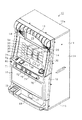
以下、遊技機の一種である回胴式遊技機、具体的にはスロットマシンに適用した場合の一実施の形態を、図面に基づいて詳細に説明する。図1はスロットマシン10の正面図、図2はスロットマシン10の前面扉12を閉じた状態の斜視図、図3はスロットマシン10の前面扉12を開いた状態の斜視図、図4は前面扉12の背面図、図5は筐体11の正面図である。   Hereinafter, an embodiment in the case of application to a spinning cylinder type gaming machine, which is a kind of gaming machine, specifically, a slot machine will be described in detail with reference to the drawings. 1 is a front view of the slot machine 10, FIG. 2 is a perspective view of the slot machine 10 with the front door 12 closed, FIG. 3 is a perspective view of the slot machine 10 with the front door 12 opened, and FIG. 5 is a rear view of the door 12, and FIG.

図1〜図5に示すように、スロットマシン10は、その外殻を形成する筐体11を備えている。筐体11は、木製板状に形成された天板11a、底板11b、背板11c、左側板11d及び右側板11eからなり、隣接する各板11a〜11eが接着等の固定手段によって固定されることにより、全体として前面を開放した箱状に形成されている。なお、各板11a〜11eは木製のパネルによって構成する以外に、合成樹脂製パネル又は金属製パネルによって構成してもよいし、合成樹脂材料又は金属材料によって一体の箱状に形成することによって構成してもよい。以上のように構成された筐体11は、遊技場への設置の際にいわゆる島設備に対し釘を打ち付ける等して取り付けられる。   As shown in FIGS. 1 to 5, the slot machine 10 includes a housing 11 that forms an outer shell thereof. The casing 11 includes a top plate 11a, a bottom plate 11b, a back plate 11c, a left side plate 11d, and a right side plate 11e formed in a wooden plate shape, and the adjacent plates 11a to 11e are fixed by fixing means such as adhesion. Thus, it is formed in a box shape with the front surface opened as a whole. In addition, each board 11a-11e may be comprised with a synthetic resin panel or a metal panel other than being comprised with a wooden panel, or it is comprised by forming in the box shape integral with a synthetic resin material or a metal material. May be. The casing 11 configured as described above is attached by, for example, driving nails against a so-called island facility at the time of installation in the game hall.

筐体11の前面側には、前面開閉扉としての前面扉12が開閉可能に取り付けられている。すなわち、筐体11の左側板11dには、上下一対の支軸25a,25bが設けられている。支軸25a,25bは上方に向けて突出された先細り形状の軸部を備えている。一方、前面扉12には、各支軸25a,25bに対応して当該支軸25a,25bの軸部が挿入される挿入孔を備えた支持金具26a,26bが設けられている。そして、各支軸25a,25bの上方に支持金具26a,26bを配置させた上で前面扉12を降下させることにより、支持金具26a,26bの挿入孔に支軸25a,25bの軸部が挿入された状態とされる。これにより、前面扉12は筐体11に対して両支軸25a,25bを結ぶ上下方向へ延びる開閉軸線を中心として回動可能に支持され、その回動によって筐体11の前面開放側を開放したり閉鎖することができるように構成されている。   A front door 12 as a front open / close door is attached to the front side of the housing 11 so as to be openable and closable. That is, the left side plate 11d of the housing 11 is provided with a pair of upper and lower support shafts 25a and 25b. Each of the support shafts 25a and 25b includes a tapered shaft portion that protrudes upward. On the other hand, the front door 12 is provided with support fittings 26a and 26b having insertion holes into which the shaft portions of the support shafts 25a and 25b are inserted corresponding to the support shafts 25a and 25b. Then, the support brackets 26a and 26b are arranged above the support shafts 25a and 25b, and the front door 12 is lowered, whereby the shaft portions of the support shafts 25a and 25b are inserted into the insertion holes of the support brackets 26a and 26b. It is assumed that it was done. Thereby, the front door 12 is supported so as to be rotatable about an opening / closing axis extending in the vertical direction connecting the both support shafts 25a and 25b with respect to the housing 11, and the front opening side of the housing 11 is opened by the rotation. It can be closed or closed.

前面扉12は、その裏面に設けられた施錠装置によって開放不能な施錠状態とされる。また、前面扉12の右端側上部には解錠操作部たるキーシリンダ20が設けられている。キーシリンダ20は施錠装置と一体化されており、キーシリンダ20に対する所定のキー操作によって前記施錠状態が解除されるように構成されている。そこで、施錠装置を含むロック機構について概略を説明する。   The front door 12 is brought into a locked state that cannot be opened by a locking device provided on the rear surface. Further, a key cylinder 20 serving as an unlocking operation unit is provided at the upper right side of the front door 12. The key cylinder 20 is integrated with a locking device, and is configured such that the locked state is released by a predetermined key operation on the key cylinder 20. Therefore, an outline of the lock mechanism including the locking device will be described.

前面扉12の右端側、すなわち前面扉12の開閉軸の反対側には、その裏面に施錠装置が設けられている。施錠装置は、上下方向に延び前面扉12に固定された基枠と、基枠の上部から前面扉12の前方に延びるように設けられたキーシリンダ20と、基枠に対して上下方向に移動可能に組み付けられた長尺状の連動杆21とを備えている。そして、施錠装置のうちキーシリンダ20だけが前面扉12の前方に突出した状態で設けられている。キーシリンダ20が設けられる位置は前面扉12の中でも肉厚の薄い上部位置とされており、その結果、全長の短い汎用性のあるキーシリンダ20を採用することができる。なお、本実施の形態では、キーシリンダ20として、不正解錠防止機能の高いオムロック(商標名)が用いられている。連動杆21は、キーシリンダ20に差し込んだキーを時計回りに操作することで下方へ移動される。連動杆21には、鉤形状をなす上下一対の鉤金具22が設けられており、筐体11に対して前面扉12を閉鎖した際には、鉤金具22が筐体11側の支持金具23に係止されて施錠状態となる。なお、鉤金具22には施錠状態を維持する側へ付勢するコイルバネ等の付勢部材が設けられている。キーシリンダ20に対してキーが時計回りに操作されると、連動杆21が下方に移動し、前記付勢部材の付勢力に抗して鉤金具22が移動されることにより当該鉤金具22と支持金具23との係止状態が解除され、筐体11に対する前面扉12の施錠状態が解除される。   On the right end side of the front door 12, that is, on the opposite side of the opening / closing axis of the front door 12, a locking device is provided on the back surface. The locking device extends vertically and is fixed to the front door 12, a key cylinder 20 provided so as to extend from the upper part of the base frame to the front of the front door 12, and moves vertically with respect to the base frame. It is provided with a long interlocking rod 21 assembled as possible. And only the key cylinder 20 is provided in the state which protruded ahead of the front door 12 among the locking devices. The position where the key cylinder 20 is provided is the thin upper portion of the front door 12, and as a result, a versatile key cylinder 20 having a short overall length can be employed. In the present embodiment, Omlock (trade name) having a high function of preventing unauthorized unlocking is used as the key cylinder 20. The interlocking rod 21 is moved downward by operating the key inserted into the key cylinder 20 clockwise. The interlocking saddle 21 is provided with a pair of upper and lower saddle fittings 22 having a bowl shape. When the front door 12 is closed with respect to the casing 11, the saddle fitting 22 is supported on the casing 11 side. Is locked. In addition, the urging member 22 is provided with an urging member such as a coil spring for urging to the side maintaining the locked state. When the key is operated clockwise with respect to the key cylinder 20, the interlocking rod 21 moves downward, and the saddle fitting 22 is moved against the biasing force of the biasing member. The locked state with the support fitting 23 is released, and the locked state of the front door 12 with respect to the housing 11 is released.

前面扉12の中央部上寄りには、遊技者に遊技状態を報知する遊技パネル30が設けられている。遊技パネル30には、縦長の3つの表示窓31L,31M,31Rが横並びとなるように形成されている。表示窓31L,31M,31Rは透明又は半透明な材質により構成されており、各表示窓31L,31M,31Rを通じてスロットマシン10の内部が視認可能な状態となっている。なお、各表示窓31L,31M,31Rを1つにまとめて共通の表示窓としてもよい。   A game panel 30 for notifying the player of the game state is provided above the center of the front door 12. In the game panel 30, three vertically long display windows 31L, 31M, 31R are formed side by side. The display windows 31L, 31M, 31R are made of a transparent or translucent material, and the inside of the slot machine 10 is visible through the display windows 31L, 31M, 31R. The display windows 31L, 31M, and 31R may be combined into a single display window.

図3に示すように、筐体11は仕切り板40によりその内部が上下2分割されており、仕切り板40の上部には、可変表示手段を構成するリールユニット41が取り付けられている。リールユニット41は、円筒状(円環状)にそれぞれ形成された左リール42L,中リール42M,右リール42Rを備えている。なお、各リール42L,42M,42Rは少なくとも無端状ベルトとして構成されていればよく、円筒状(円環状)に限定されるものではない。各リール42L,42M,42Rは、その中心軸線が当該リールの回転軸線となるように回転可能に支持されている。各リール42L,42M,42Rの回転軸線は略水平方向に延びる同一軸線上に配設され、それぞれのリール42L,42M,42Rが各表示窓31L,31M,31Rと1対1で対応している。従って、各リール42L,42M,42Rの表面の一部はそれぞれ対応する表示窓31L,31M,31Rを通じて視認可能な状態となっている。また、リール42L,42M,42Rが正回転すると、各表示窓31L,31M,31Rを通じてリール42L,42M,42Rの表面は上から下へ向かって移動しているかのように映し出される。   As shown in FIG. 3, the inside of the housing 11 is vertically divided into two by a partition plate 40, and a reel unit 41 constituting variable display means is attached to the upper portion of the partition plate 40. The reel unit 41 includes a left reel 42L, a middle reel 42M, and a right reel 42R each formed in a cylindrical shape (annular shape). The reels 42L, 42M, and 42R may be configured as at least an endless belt, and are not limited to a cylindrical shape (annular shape). Each of the reels 42L, 42M, and 42R is rotatably supported so that the central axis thereof is the rotation axis of the reel. The rotation axes of the reels 42L, 42M, and 42R are arranged on the same axis extending in the substantially horizontal direction, and the reels 42L, 42M, and 42R correspond to the display windows 31L, 31M, and 31R on a one-to-one basis. . Accordingly, a part of the surface of each reel 42L, 42M, 42R is visible through the corresponding display windows 31L, 31M, 31R. Further, when the reels 42L, 42M, and 42R are rotated forward, the surfaces of the reels 42L, 42M, and 42R are projected as if moving from top to bottom through the display windows 31L, 31M, and 31R.

これら各リール42L,42M,42Rは、それぞれがステッピングモータ61L,61M,61Rに連結されており、各ステッピングモータ61L,61M,61Rの駆動により各リール42L,42M,42Rが個別に、即ちそれぞれ独立して回転駆動し得る構成となっている。これら各リール42L,42M,42Rは同様の構成をしているため、ここでは左リール42Lを例に挙げて図6に基づいて説明する。なお、図6は左リール42Lの組立斜視図である。   Each of the reels 42L, 42M, and 42R is coupled to the stepping motors 61L, 61M, and 61R, and each of the reels 42L, 42M, and 42R is individually, that is, independently, driven by the stepping motors 61L, 61M, and 61R. Thus, it can be rotationally driven. Since these reels 42L, 42M, and 42R have the same configuration, here, the left reel 42L will be described as an example with reference to FIG. FIG. 6 is an assembled perspective view of the left reel 42L.

左リール42Lは、円筒状のかごを形成する円筒骨格部材50と、その外周面において無端状に巻かれた帯状のベルトとを備えている。そして、その巻かれた状態を維持するように、ベルトの長辺両側に沿って形成された一対のシール部を介して円筒骨格部材50に貼付されている。前記ベルトの外周面には、識別情報としての図柄が等間隔ごとに多数印刷されている。円筒骨格部材50の中心部にはボス部51形成されており、円盤状のボス補強板52を介して左リール用ステッピングモータ61Lの駆動軸に取り付けられている。従って、左リール用ステッピングモータ61Lの駆動軸が回転することによりその駆動軸を中心として円筒骨格部材50が自転するように回転され、左リール42Lが円環状のリール面に沿って周回するようになっている。   The left reel 42L includes a cylindrical skeleton member 50 that forms a cylindrical cage, and a belt-like belt wound endlessly on the outer peripheral surface thereof. And it is affixed on the cylindrical skeleton member 50 through a pair of seal parts formed along the both sides of the long side of the belt so as to maintain the wound state. A large number of symbols as identification information are printed at equal intervals on the outer peripheral surface of the belt. A boss 51 is formed at the center of the cylindrical skeleton member 50, and is attached to the drive shaft of the left reel stepping motor 61L via a disc-shaped boss reinforcing plate 52. Accordingly, when the drive shaft of the left reel stepping motor 61L is rotated, the cylindrical skeleton member 50 is rotated around the drive shaft so that the left reel 42L circulates along the annular reel surface. It has become.

左リール用ステッピングモータ61Lは、リールユニット41(図3)内において起立状態に配置されたモータプレート53の側面にねじ54で固定されている。モータプレート53には、発光素子55aと受光素子55bとが所定間隔をおいて保持されたリールインデックスセンサ(回転位置検出センサ)55が設置されている。一方、左リール42Lと一体化されたボス補強板52には、半径方向に延びるセンサカットバン56の基端部56bがねじ57で固定されている。このセンサカットバン56の先端部56aは、略直角に屈曲されてリールインデックスセンサ55の両素子55a,55bの間を通過できるように位置合わせがなされている。そして、左リール42Lが1回転するごとにセンサカットバン56の先端部56aの通過をリールインデックスセンサ55が検出し、その検出の都度、後述する主制御装置131に検出信号が出力される。従って、主制御装置131はこの検出信号に基づいて左リール42Lの角度位置を1回転ごとに確認し補正できる。   The left reel stepping motor 61L is fixed to the side surface of the motor plate 53 arranged in an upright state in the reel unit 41 (FIG. 3) with screws 54. The motor plate 53 is provided with a reel index sensor (rotational position detection sensor) 55 in which a light emitting element 55a and a light receiving element 55b are held at a predetermined interval. On the other hand, the base end portion 56b of the sensor cut bun 56 extending in the radial direction is fixed to the boss reinforcing plate 52 integrated with the left reel 42L with a screw 57. The front end portion 56a of the sensor cut bun 56 is bent at a substantially right angle and is positioned so as to pass between both elements 55a and 55b of the reel index sensor 55. Each time the left reel 42L makes one rotation, the reel index sensor 55 detects the passage of the front end portion 56a of the sensor cut bun 56, and a detection signal is output to the main controller 131 described later each time the detection is made. Therefore, main controller 131 can confirm and correct the angular position of left reel 42L for each rotation based on this detection signal.

ステッピングモータ61Lは例えば504パルスの駆動信号(励磁信号あるいは励磁パルスとも言う。以下同じ)を与えることにより1回転されるように設定されており、この励磁パルスによってステッピングモータ61Lの回転位置、すなわち左リール42Lの回転位置が制御される。   The stepping motor 61L is set to rotate once by giving, for example, a drive signal of 504 pulses (also referred to as an excitation signal or an excitation pulse; the same applies hereinafter), and the rotation position of the stepping motor 61L, that is, left The rotational position of the reel 42L is controlled.

各リール42L,42M,42Rの各ベルト上には、その長辺方向(周回方向)に複数個、具体的には21個の図柄が描かれている。従って、所定の位置においてある図柄から次の図柄へ切り替えるには24パルス(=504パルス÷21図柄)を要する。そして、リールインデックスセンサ55の検出信号が出力された時点からのパルス数により、どの図柄が表示窓31L,31M,31Rから視認可能な状態となっているかを認識したり、任意の図柄を表示窓31L,31M,31Rから視認可能な状態としたりする制御を行うことができる。   On each belt of each of the reels 42L, 42M, and 42R, a plurality of, specifically, 21 symbols are drawn in the long side direction (circumferential direction). Therefore, 24 pulses (= 504 pulses ÷ 21 symbols) are required to switch from one symbol to the next symbol at a predetermined position. Based on the number of pulses from when the detection signal of the reel index sensor 55 is output, it is recognized which symbols are visible from the display windows 31L, 31M, and 31R, and arbitrary symbols are displayed on the display window. Control to make it visible from 31L, 31M, 31R can be performed.

各リール42L,42M,42Rに付された図柄のうち、表示窓31L,31M,31Rを介して全体を視認可能な図柄数は、主として表示窓31L,31M,31Rの上下方向の長さによって決定される所定数に限られている。本実施形態では各リール3個ずつとされている。このため、各リール42L,42M,42Rがすべて停止している状態では、3×3=9個の図柄が遊技者に視認可能な状態となる。   Of the symbols attached to the reels 42L, 42M, and 42R, the number of symbols that can be visually recognized through the display windows 31L, 31M, and 31R is mainly determined by the vertical lengths of the display windows 31L, 31M, and 31R. Is limited to a predetermined number. In this embodiment, three reels are provided. For this reason, when all the reels 42L, 42M, and 42R are stopped, 3 × 3 = 9 symbols are visible to the player.

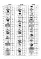
ここで、各リール42L,42M,42Rに付される図柄について説明する。図7には、左リール42L,中リール42M,右リール42Rのそれぞれに巻かれるベルトに描かれた図柄配列が示されている。同図に示すように、各リール42L,42M,42Rにはそれぞれ21個の図柄が一列に設けられている。また、各リール42L,42M,42Rに対応して番号が0〜20まで付されているが、これら番号は主制御装置131が表示窓から視認可能な状態となっている図柄を認識するための番号であり、リール42L,42M,42Rに実際に付されているわけではない。但し、以下の説明では当該番号を使用して説明する。   Here, the symbols attached to the reels 42L, 42M, and 42R will be described. FIG. 7 shows a symbol arrangement drawn on the belt wound around each of the left reel 42L, the middle reel 42M, and the right reel 42R. As shown in the figure, each of the reels 42L, 42M, and 42R is provided with 21 symbols in a row. In addition, numbers 0 to 20 are assigned to the reels 42L, 42M, and 42R, and these numbers are used for the main controller 131 to recognize the symbols that are visible from the display window. It is a number and is not actually attached to the reels 42L, 42M, 42R. However, in the following description, the number is used for explanation.

図柄としては、「リプレイ」図柄(例えば、左ベルト20番目)、「ベル」図柄(例えば、左ベルト19番目)、「青年」図柄(例えば、左ベルト18番目)、「7」図柄(例えば、左ベルト17番目)、「チェリー」図柄(例えば、左ベルト13番目)、「チャンス」図柄(例えば、左ベルト12番目)、「スイカ」図柄(例えば、左ベルト9番目)、「リーチ」図柄(例えば、左ベルト6番目)、「ラッキー」図柄(例えば、左ベルト1番目)の9種類がある。そして、図7に示すように、各リール42L,42M,42Rに巻かれるベルトにおいて、各種図柄の数や配置順序は全く異なっている。   The symbols include “Replay” symbol (for example, left belt 20th), “Bell” symbol (for example, left belt 19th), “Youth” symbol (for example, left belt 18th), “7” symbol (for example, (Left belt 17th), “Cherry” design (eg, left belt 13th), “Chance” design (eg, left belt 12th), “Watermelon” design (eg, left belt 9th), “Reach” design ( For example, there are nine types: the 6th left belt) and the “Lucky” symbol (for example, 1st left belt). As shown in FIG. 7, the number of symbols and the arrangement order of the various symbols are completely different in the belts wound around the reels 42L, 42M, and 42R.

なお、リールユニット41の各リール42L,42M,42Rは識別情報を可変表示する可変表示手段の一例であり、主表示部を構成する。但し、可変表示手段は、図柄を周方向に可変表示する構成であれば、これ以外の構成であってもよい。例えば、ベルトを自転させるのではなく周回させるタイプ等の他の機械的なリール構成としてもよく、また、機械的なリール構成に加えて、液晶表示器、ドットマトリックス表示器等の電気的表示により識別情報を可変表示させるものを設けてもよく、この場合は表示形態に豊富なバリエーションをもたせることが可能となる。   Each reel 42L, 42M, 42R of the reel unit 41 is an example of variable display means for variably displaying identification information, and constitutes a main display unit. However, the variable display means may have a configuration other than this as long as the symbol is variably displayed in the circumferential direction. For example, other mechanical reel configurations such as a type in which the belt is rotated instead of rotating may be used. In addition to the mechanical reel configuration, an electric display such as a liquid crystal display or a dot matrix display may be used. A device for variably displaying the identification information may be provided, and in this case, it is possible to give abundant variations in the display form.

遊技パネル30には、各表示窓31L,31M,31Rを結ぶようにして、横方向へ平行に3本、斜め方向へたすき掛けに2本、計5本の組合せラインが付されている。勿論、最大組合せライン数を6以上としてもよく、5未満としてもよく、所定条件に応じて最大組合せライン数を変更するようにしてもよい。これら各組合せラインに対応して、表示窓31L,31M,31R群の正面から見て左側には有効ライン表示部32,33,34が設けられている。第1有効ライン表示部32は組合せラインのうち中央の横ライン(中ライン)が有効化された場合に点灯等によって表示報知される。第2有効ライン表示部33は組合せラインのうち上下の横ライン(上ライン及び下ライン)が有効化された場合に点灯等によって表示報知される。第3有効ライン表示部34は組合せラインのうち一対の斜めライン(右下がりライン及び右上がりライン)が有効化された場合に点灯等によって表示報知される。そして、有効化された組合せライン、すなわち有効ライン上に図柄が所定の組合せで停止した場合に入賞となり、予め定められたメダル数の払出処理や、特別遊技状態たるBBゲーム等のボーナスゲームへの移行処理などが実行される。   A total of five combination lines are attached to the game panel 30 such that three display windows 31L, 31M, and 31R are connected to each other and three in parallel in the horizontal direction and two in diagonal directions. Of course, the maximum number of combined lines may be 6 or more, or less than 5, and the maximum number of combined lines may be changed according to a predetermined condition. Corresponding to these combination lines, effective line display sections 32, 33, and 34 are provided on the left side when viewed from the front of the display windows 31L, 31M, and 31R. The first effective line display unit 32 is notified by lighting or the like when the central horizontal line (middle line) of the combination lines is activated. When the upper and lower horizontal lines (upper line and lower line) of the combination lines are activated, the second effective line display unit 33 is displayed and notified by lighting or the like. The third effective line display unit 34 is notified by lighting or the like when a pair of diagonal lines (downward right line and upward right line) of the combination lines is activated. And, when the combination line that has been activated, that is, when the symbol is stopped in a predetermined combination on the activated line, a prize is awarded, and a payout process for a predetermined medal number or a bonus game such as a BB game that is in a special gaming state is awarded. Migration processing etc. are executed.

図8には、入賞となる図柄の組合せと、入賞となった場合に払い出されるメダル払出枚数とが示されている。   FIG. 8 shows a combination of symbols for winning and the number of medals to be paid out when winning.

メダル払出が行われる小役入賞としては、スイカ入賞と、ベル入賞と、チェリー入賞とがある。有効ライン上に左から「スイカ」図柄、「スイカ」図柄、「スイカ」図柄と並んで停止した場合、スイカ入賞として15枚のメダル払出、有効ライン上に左から「ベル」図柄、「ベル」図柄、「ベル」図柄と並んで停止した場合、ベル入賞として11枚のメダル払出が行われる。また、左リール42Lの「チェリー」図柄が有効ライン上に停止した場合、チェリー入賞として2枚のメダル払出が行われる。即ち、チェリー入賞の場合には、中リール42M及び右リール42Rの有効ライン上に停止する図柄はどのような図柄であってもよい。故に、左リール42Lの複数の有効ラインが重なる位置(具体的には上段又は下段)に「チェリー」図柄が停止した場合には、各有効ライン上にてチェリー入賞が成立し、その重なった有効ラインの数を乗算した分だけのメダル払出が行われる。結果として、本実施形態では4枚のメダル払出が行われる。   Small prizes for which medals are paid out include a watermelon prize, a bell prize, and a cherry prize. When stopped alongside the “Watermelon” symbol, “Watermelon” symbol, and “Watermelon” symbol from the left on the active line, 15 medals are paid out as a watermelon prize, “Bell” symbol from the left, “Bell” on the active line In the case of stopping alongside the symbol and the “bell” symbol, eleven medals are paid out as a bell prize. When the “cherry” symbol on the left reel 42L stops on the active line, two medals are paid out as a cherry prize. That is, in the case of a cherry winning, any symbol that stops on the active line of the middle reel 42M and the right reel 42R may be any symbol. Therefore, when the “cherry” symbol stops at the position where the plurality of effective lines of the left reel 42L overlap (specifically, the upper stage or the lower stage), a cherry winning is established on each active line, and the overlapping effective The medal is paid out by multiplying the number of lines. As a result, in this embodiment, four medals are paid out.

また、遊技状態が移行する状態移行入賞としてBB入賞がある。有効ライン上に左から「7」図柄、「7」図柄、「7」図柄と並んで停止した場合、BB入賞として遊技状態が特別遊技状態たるBBゲームに移行する。但し、「7」図柄が有効ライン上に左・中・右と並んで停止したとしても、メダル払出は行われない。すなわち、「7」図柄の組合せが有効ライン上に成立した際には、BBゲームに移行するのみである。換言すれば、「7」図柄は、遊技状態をBBゲームに移行させるための状態移行図柄であるといえる。   Further, there is a BB winning as a state transition winning in which the gaming state shifts. When the “7” symbol, “7” symbol, and “7” symbol are stopped from the left on the active line, the game state shifts to the BB game where the gaming state is the special gaming state as a BB winning. However, even if the “7” symbol stops along the left, middle and right on the active line, no medal is paid out. That is, when the combination of the “7” symbols is established on the active line, only the BB game is entered. In other words, it can be said that the “7” symbol is a state transition symbol for shifting the gaming state to the BB game.

更に、有効ライン上に左から「リプレイ」図柄、「リプレイ」図柄、「リプレイ」図柄と並んで停止した場合には、再遊技入賞となる。再遊技入賞が成立すると、メダル払出や状態移行は行われないものの、遊技者は所有するメダルを減らすことなく且つメダルを投入することなく次ゲームの遊技を行うことが可能となる。   Furthermore, when the “replay” symbol, “replay” symbol, and “replay” symbol are stopped from the left on the active line, a re-game win is awarded. When the re-game winning is established, the medal payout and the state transition are not performed, but the player can play the next game without reducing the medals owned and without inserting medals.

加えて、遊技状態が後述するRBゲームである場合に限り、有効ライン上に左から「リプレイ」図柄、「リプレイ」図柄、「チャンス」図柄と並んで停止した場合と、有効ライン上に左から「リプレイ」図柄、「リプレイ」図柄、「ラッキー」図柄と並んで停止した場合に、JAC入賞として15枚のメダル払出が行われる。   In addition, only when the gaming state is an RB game, which will be described later, when stopped alongside the “Replay” symbol, “Replay” symbol, “Chance” symbol from the left on the active line, and from the left on the active line When the “replay” symbol, “replay” symbol, and “lucky” symbol are stopped alongside, 15 medals are paid out as a JAC prize.

その他の場合、即ち有効ライン上に左リール42Lの「チェリー」図柄が停止せず、また有効ライン上に上記した図柄の組合せが停止しなかった場合には、メダル払出や遊技状態の移行等は一切行われない。すなわち、左リール42Lの「チャンス」図柄及び「ラッキー」図柄、中リール42Mと右リール42Rの「チェリー」図柄、各リール42L,42M,42Rの「青年」図柄及び「リーチ」図柄は、入賞と一切関与していない。換言すれば、上記各図柄は、遊技者に付与される特典と無関係な無特典図柄であると言える。このように、各リール42L,42M,42Rには、例えば「ベル」図柄等の入賞と関係する特典図柄と、例えば「青年」図柄等の入賞と無関係な無特典図柄がそれぞれ付されている。なお、以下では、各入賞と対応する図柄の組合せを入賞図柄の組合せともいう。例えば、BB図柄の組合せとは、BB入賞となる図柄の組合せ、すなわち「7」図柄、「7」図柄、「7」図柄の組合せである。   In other cases, that is, when the “cherry” symbol of the left reel 42L does not stop on the active line and the combination of the symbols described above does not stop on the active line, the medal payout, the transition of the gaming state, etc. Not done at all. That is, the “chance” symbol and “lucky” symbol of the left reel 42L, the “cherry” symbol of the middle reel 42M and the right reel 42R, the “young” symbol and the “reach” symbol of each reel 42L, 42M, 42R Not involved at all. In other words, it can be said that each of the symbols is a no-benefits symbol unrelated to the privilege given to the player. As described above, each of the reels 42L, 42M, and 42R is provided with a bonus symbol related to winning such as a “bell” symbol and a non-privileged symbol irrelevant to winning such as a “young” symbol, for example. In the following, a combination of symbols corresponding to each prize is also referred to as a combination of winning symbols. For example, the BB symbol combination is a symbol BB winning combination, that is, a combination of “7” symbol, “7” symbol, and “7” symbol.

遊技パネル30の下方左側には、各リール42L,42M,42Rを一斉(同時である必要はない)に回転開始させるために操作されるスタートレバー71が設けられている。スタートレバー71はリール42L,42M,42Rを回転開始、すなわち図柄の可変表示を開始させるべく操作される開始操作手段又は始動操作手段を構成する。スタートレバー71は、遊技者がゲームを開始するときに手で押し操作するレバーであり、手が離れたあと初期位置に自動復帰する。ちなみに、本スロットマシン10におけるスタートレバー71は、手が離れたあと初期位置に自動復帰するまでに数10msecを要するように構成されている。メダルが所定数投入されているときにこのスタートレバー71が操作されると、各リール42L,42M,42Rが一斉に回転を始める。   On the lower left side of the game panel 30, a start lever 71 is provided that is operated to start rotation of the reels 42L, 42M, and 42R all at once (not necessarily simultaneously). The start lever 71 constitutes start operation means or start operation means operated to start rotation of the reels 42L, 42M, and 42R, that is, to start variable display of symbols. The start lever 71 is a lever that is pushed by the hand when the player starts the game, and automatically returns to the initial position after the hand is released. Incidentally, the start lever 71 in the slot machine 10 is configured to require several tens of milliseconds until it automatically returns to the initial position after the hand is released. When the start lever 71 is operated when a predetermined number of medals are inserted, the reels 42L, 42M, and 42R start to rotate all at once.

スタートレバー71の右側には、回転している各リール42L,42M,42Rを個別に停止させるために操作されるボタン状のストップスイッチ72,73,74が設けられている。各ストップスイッチ72,73,74は停止対象となるリール42L,42M,42Rに対応する表示窓31L,31M,31Rの直下にそれぞれ配置されている。すなわち、左ストップスイッチ72が操作された場合には左リール42Lの回転が停止し、中ストップスイッチ73が操作された場合には中リール42Mの回転が停止し、右ストップスイッチ74が操作された場合には右リール42Rの回転が停止する。ストップスイッチ72,73,74はリール42L,42M,42Rの回転に基づく図柄の可変表示を停止させるべく操作される停止操作手段を構成する。各ストップスイッチ72,73,74は、左リール42Lが回転を開始してから所定時間が経過すると停止させることが可能な状態となり、かかる状態中には図示しないランプが点灯表示されることによって停止操作が可能であることが報知され、回転が停止すると消灯されるようになっている。   On the right side of the start lever 71, button-like stop switches 72, 73, 74 that are operated to individually stop the rotating reels 42L, 42M, 42R are provided. Each of the stop switches 72, 73, 74 is arranged directly below the display windows 31L, 31M, 31R corresponding to the reels 42L, 42M, 42R to be stopped. That is, when the left stop switch 72 is operated, the rotation of the left reel 42L is stopped. When the middle stop switch 73 is operated, the rotation of the middle reel 42M is stopped and the right stop switch 74 is operated. In this case, the rotation of the right reel 42R is stopped. The stop switches 72, 73, 74 constitute stop operation means operated to stop the variable display of symbols based on the rotation of the reels 42L, 42M, 42R. Each of the stop switches 72, 73, 74 can be stopped when a predetermined time elapses after the left reel 42L starts rotating, and is stopped by lighting a lamp (not shown) during such a state. It is notified that the operation is possible, and is turned off when the rotation stops.

表示窓31L,31M,31Rの下方右側には、投資価値としてのメダルを投入するためのメダル投入口75が設けられている。メダル投入口75は投資価値を入力する入力手段を構成する。また、メダル投入口75が遊技者によりメダルを直接投入するという動作を伴う点に着目すれば、投資価値を直接入力する直接入力手段を構成するものともいえる。   On the lower right side of the display windows 31L, 31M, 31R, there is provided a medal slot 75 for inserting a medal as an investment value. The medal slot 75 constitutes an input means for inputting the investment value. Further, if attention is paid to the point that the medal insertion slot 75 is accompanied by the operation of directly inserting the medal by the player, it can be said that the medal insertion slot 75 constitutes a direct input means for directly inputting the investment value.

メダル投入口75から投入されたメダルは、前面扉12の背面に設けられた通路切替手段としてのセレクタ84によって貯留用通路81か排出用通路82のいずれかへ導かれる。すなわち、セレクタ84にはメダル通路切替ソレノイド83が設けられ、そのメダル通路切替ソレノイド83の非励磁時には排出用通路82側とされ、励磁時には貯留用通路81側に切り替えられるようになっている。貯留用通路81に導かれたメダルは、筐体11の内部に収納されたホッパ装置91へと導かれる。一方、排出用通路82に導かれたメダルは、前面扉12の前面下部に設けられたメダル排出口17からメダル受け皿18へと導かれ、遊技者に返還される。   The medals inserted from the medal insertion slot 75 are guided to either the storage passage 81 or the discharge passage 82 by the selector 84 as passage switching means provided on the back surface of the front door 12. That is, the selector 84 is provided with a medal path switching solenoid 83, which is set to the discharge path 82 side when the medal path switching solenoid 83 is not excited, and switched to the storage path 81 side when excited. The medal guided to the storage passage 81 is guided to the hopper device 91 housed in the housing 11. On the other hand, the medal guided to the discharge passage 82 is guided to the medal tray 18 from the medal discharge port 17 provided in the lower front portion of the front door 12 and returned to the player.

メダルを遊技者に付与する払出手段としてのホッパ装置91は、メダルを貯留する貯留タンク92と、メダルを遊技者に払い出す払出装置93とより構成されている。払出装置93は、図示しないメダル払出用回転板を回転させることにより、排出用通路82の中央右部に設けられた開口94へメダルを排出し、排出用通路82を介してメダル受け皿18へメダルを払い出すようになっている。また、ホッパ装置91の右方には、貯留タンク92内に所定量以上のメダルが貯留されることを回避するための予備タンク95が設けられている。ホッパ装置91の貯留タンク92内部には、この貯留タンク92から予備タンク95へとメダルを排出する誘導プレート96が設けられている。したがって、誘導プレート96が設けられた高さ以上にメダルが貯留された場合、かかるメダルが予備タンク95に貯留されることとなる。   A hopper device 91 as a payout means for giving a medal to a player is composed of a storage tank 92 for storing the medal and a payout device 93 for paying out the medal to the player. The payout device 93 rotates a medal payout rotating plate (not shown) to discharge the medal to the opening 94 provided in the central right part of the discharge passage 82 and to the medal tray 18 through the discharge passage 82. To come out. Further, a reserve tank 95 is provided on the right side of the hopper device 91 in order to avoid storing a predetermined amount or more of medals in the storage tank 92. A guide plate 96 for discharging medals from the storage tank 92 to the reserve tank 95 is provided inside the storage tank 92 of the hopper device 91. Therefore, when medals are stored more than the height at which the guide plate 96 is provided, the medals are stored in the reserve tank 95.

メダル投入口75の下方には、ボタン状の返却スイッチ76が設けられている。返却スイッチ76は、メダル投入口75に投入されたメダルがセレクタ84内に詰まった際に押されるスイッチであり、このスイッチが押されることによりセレクタ84が機械的に連動して動作され、当該セレクタ84内に詰まったメダルがメダル排出口17より返却されるようになっている。   A button-like return switch 76 is provided below the medal slot 75. The return switch 76 is a switch that is pressed when a medal inserted into the medal slot 75 is jammed in the selector 84. When this switch is pressed, the selector 84 is mechanically operated to operate the selector 84. The medals packed in 84 are returned from the medal discharge port 17.

表示窓31L,31M,31Rの下方左側には、投資価値としてのクレジットされた仮想メダルを一度に3枚投入するためのボタン状の第1クレジット投入スイッチ77が設けられている。また、第1クレジット投入スイッチ77の左方には当該スイッチ77よりも小さなボタン状のスイッチとして、第2クレジット投入スイッチ78及び第3クレジット投入スイッチ79が設けられている。第2クレジット投入スイッチ78はクレジットされた仮想メダルを一度に2枚投入するためのものであり、第3クレジット投入スイッチ79は仮想メダルを1枚投入するためのものである。各クレジット投入スイッチ77〜79は前記メダル投入口75とともに投資価値を入力する入力手段を構成する。また、メダル投入口75が遊技者によりメダルを直接投入するという動作を伴うのに対し各クレジット投入スイッチ77〜79は貯留記憶に基づく仮想メダルの投入という動作を伴うに過ぎない点に着目すれば、投資価値を間接入力する間接入力手段を構成するものともいえる。   On the lower left side of the display windows 31L, 31M, 31R, there is provided a button-like first credit insertion switch 77 for inserting three virtual medals credited as investment values at a time. Further, on the left side of the first credit insertion switch 77, a second credit insertion switch 78 and a third credit insertion switch 79 are provided as button switches smaller than the switch 77. The second credit insertion switch 78 is for inserting two credited virtual medals at a time, and the third credit insertion switch 79 is for inserting one virtual medal. Each of the credit insertion switches 77 to 79, together with the medal insertion slot 75, constitutes an input means for inputting an investment value. Further, if the medal insertion slot 75 is accompanied by an operation of directly inserting a medal by the player, each credit insertion switch 77 to 79 is only accompanied by an operation of inserting a virtual medal based on the storage memory. It can also be said that it constitutes an indirect input means for indirectly inputting the investment value.

なお、第1クレジット投入スイッチ77は、1ゲームにつき投入できるメダル最大数(3枚)に達していないことを促すため、図示しない発光部材としてのランプが内蔵されている。当該ランプは、第1クレジット投入スイッチ77のスイッチ操作が有効である状況時において点灯されて当該スイッチ77の操作を促すが、クレジットされた仮想メダルが存在しない場合や既に3枚のメダル投入がなされている状況下では消灯される。ここで、上記点灯に代えて、点滅させてメダル投入の促しを遊技者に一層分かり易くしてもよい。   The first credit insertion switch 77 has a built-in lamp as a light emitting member (not shown) to urge that the maximum number of medals that can be inserted per game (three) has not been reached. The lamp is turned on when the switch operation of the first credit insertion switch 77 is valid and prompts the operation of the switch 77. However, when there is no credited virtual medal or three medals have already been inserted. It is turned off under the circumstances. Here, instead of the above-described lighting, the player may make it easier to understand the prompt for medal insertion by blinking.

スタートレバー71の左側には、ボタン状の精算スイッチ80が設けられている。すなわち、本スロットマシン10では、所定の最大値(メダル50枚分)となるまでの余剰の投入メダルや入賞時の獲得メダルを仮想メダルとして貯留記憶するクレジット機能を有しており、仮想メダルが貯留記憶されている状態で精算スイッチ80が押下操作されることで、仮想メダルが現実のメダルとして払い出される。この場合、クレジットされた仮想メダルを現実のメダルとして払い出すという機能に着目すれば、精算スイッチ80は貯留記憶された遊技価値を実際に払い出すための精算操作手段を構成するものともいえる。   A button-like settlement switch 80 is provided on the left side of the start lever 71. That is, the slot machine 10 has a credit function for storing and storing surplus inserted medals up to a predetermined maximum value (for 50 medals) and winning medals as virtual medals. The virtual medal is paid out as an actual medal when the settlement switch 80 is pressed while stored and stored. In this case, if paying attention to the function of paying out the credited virtual medal as an actual medal, it can be said that the checkout switch 80 constitutes a checkout operation means for actually paying out the stored game value.

なお、所定の最大値(例えばメダル50枚分)となるまでの余剰の投入メダルや入賞時の獲得メダルを仮想メダルとして貯留記憶するように設定された「クレジットモード」と、余剰の投入メダルや入賞時の獲得メダルを現実のメダルとして払い出すように設定された「ダイレクトモード」とを切換可能としたスロットマシンの場合には、前記精算スイッチ80に、モード切換のための切換スイッチとしての機能を付加してもよい。この場合、精算スイッチ(切換スイッチ)80は、1度押されるとオン状態になり、もう1度押されるとオフ状態になり、その後押下操作が行われるごとにオンオフが切り替わるように構成される。そして、精算スイッチ80がオン状態のときにはクレジットモードとされ、精算スイッチ80がオフ状態のときにはダイレクトモードとされる。クレジットモードからダイレクトモードに切り換えられた際に仮想メダルがある場合には、その分の仮想メダルが現実のメダルとして払い出される。これにより、遊技者はクレジットモードとダイレクトモードとを切り換えることで自身の好みに応じた形式で遊技を実行することができる。かかる精算スイッチ80は投入価値及び遊技価値の取扱形式を切り換える切換操作手段を構成する。   It should be noted that the surplus inserted medals up to a predetermined maximum value (for example, 50 medals) and the “credit mode” set to store and memorize the winning medals as virtual medals, the surplus inserted medals, In the case of a slot machine that can be switched to “direct mode” set so that the winning medal at the time of winning is paid out as an actual medal, the settlement switch 80 has a function as a changeover switch for mode switching. May be added. In this case, the settlement switch (changeover switch) 80 is turned on when pressed once, turned off when pressed again, and switched on / off every time a pressing operation is performed. When the settlement switch 80 is on, the credit mode is selected. When the settlement switch 80 is off, the direct mode is selected. If there are virtual medals when the credit mode is switched to the direct mode, the virtual medals corresponding to the virtual medals are paid out as real medals. Thereby, the player can execute the game in a format according to his / her preference by switching between the credit mode and the direct mode. The settlement switch 80 constitutes a switching operation means for switching the input value and game value handling formats.

遊技パネル30の表示窓31L,31M,31R下方には、貯留記憶された仮想メダル数を表示するクレジット表示部35と、BBゲームが終了するまでに獲得できる残りのメダル数を表示する残獲得枚数表示部36と、入賞時に獲得したメダルの枚数を表示する獲得枚数表示部37とがそれぞれ設けられている。これら表示部35〜37は7セグメント表示器によって構成されているが、液晶表示器等によって代替することは当然可能である。   Below the display windows 31L, 31M, and 31R of the game panel 30, a credit display unit 35 that displays the number of virtual medals stored and stored, and the remaining number of acquired medals that displays the number of remaining medals that can be acquired before the BB game is over. A display unit 36 and an acquired number display unit 37 for displaying the number of medals acquired at the time of winning are provided. Although these display parts 35-37 are comprised by the 7 segment display, it is naturally possible to substitute by a liquid crystal display etc. FIG.

ここで、メダルがベットされる手順について説明する。遊技の開始時にメダル投入口75からメダルが投入されるとベットとなる。   Here, a procedure for betting medals will be described. If a medal is inserted from the medal slot 75 at the start of the game, a bet is placed.

すなわち、1枚目のメダルがメダル投入口75に投入されると、第1有効ライン表示部32が点灯し、そしてこれに対応する中ラインが有効ラインとなり、2枚目のメダルがメダル投入口75に投入されると、更に第2有効ライン表示部33が点灯すると共に、これに対応する上ライン及び下ラインを含む合計3本の組合せラインがそれぞれ有効ラインとなり、3枚目のメダルがメダル投入口75に投入されると、更に第3有効ライン表示部34が点灯し、そしてこれに対応する一対の斜めラインを含む合計5本の組合せライン全てが有効ラインとなる。   That is, when the first medal is inserted into the medal insertion slot 75, the first effective line display section 32 is turned on, and the corresponding middle line becomes the effective line, and the second medal is the medal insertion slot. When the number 75 is inserted, the second effective line display section 33 is turned on, and a total of three combination lines including the upper line and the lower line corresponding to the second effective line display section 33 become effective lines, respectively, and the third medal is a medal. When it is inserted into the insertion port 75, the third effective line display unit 34 is further turned on, and a total of five combination lines including a pair of diagonal lines corresponding thereto become effective lines.

また、4枚以上のメダルがメダル投入口75に投入されると、3枚を超える余剰メダルは、そのときに貯留記憶されている仮想メダルが50枚未満であれば、スロットマシン内部に貯蓄されると共にクレジット表示部35の仮想メダル数が加算表示される。一方、仮想メダル数が50枚のとき又は50枚に達したときには、セレクタ84により貯留用通路81から排出用通路82への切替がなされ、メダル排出口17からメダル受け皿18へと余剰メダルが返却される。   When four or more medals are inserted into the medal slot 75, surplus medals exceeding three are stored inside the slot machine if the number of virtual medals stored and stored at that time is less than 50. At the same time, the number of virtual medals on the credit display unit 35 is added and displayed. On the other hand, when the number of virtual medals is 50 or reaches 50, the selector 84 switches from the storage passage 81 to the discharge passage 82, and the surplus medals are returned from the medal discharge port 17 to the medal tray 18. Is done.

また、クレジット表示部35に貯留枚数が表示されている場合には、第1〜第3クレジット投入スイッチ77〜79のいずれかが押された際にも仮想メダルが投入されたこととなりベットとなる。   Further, when the stored number is displayed on the credit display unit 35, a virtual medal is inserted even when any of the first to third credit insertion switches 77 to 79 is pressed, and a bet is made. .

第3クレジット投入スイッチ79が押された際には、仮想メダルが1枚投入されたこととしてクレジット表示部35に表示されている数値が1つ減算され、第1有効ライン表示部32が点灯して中ラインが有効ラインとなる。第2クレジット投入スイッチ78が押された際には、仮想メダルが2枚投入されたこととしてクレジット表示部35に表示されている数値が2つ減算され、第1有効ライン表示部32および第2有効ライン表示部33が点灯して合計3本の組合せラインが有効ラインとなる。第1クレジット投入スイッチ77が押された際には、仮想メダルが3枚投入されたこととしてクレジット表示部35に表示されている数値が3つ減算され、全ての有効ライン表示部32〜34が点灯して合計5本の組合せラインが有効ラインとなる。   When the third credit insertion switch 79 is pressed, the numerical value displayed on the credit display unit 35 is decremented by one as a virtual medal is inserted, and the first effective line display unit 32 is turned on. The middle line becomes the active line. When the second credit insertion switch 78 is pressed, two numerical values displayed on the credit display unit 35 as two virtual medals are inserted are subtracted, and the first valid line display unit 32 and the second The effective line display unit 33 is turned on, and a total of three combination lines become effective lines. When the first credit insertion switch 77 is pressed, three numerical values displayed on the credit display unit 35 are subtracted as three virtual medals are inserted, and all the effective line display units 32 to 34 are displayed. Lights up and a total of five combination lines become effective lines.

なお、第1〜第3クレジット投入スイッチ77〜79のいずれかが押された際に投入されるべき仮想メダルが貯留されていない場合、例えばクレジット表示部35の表示が2のときに第1クレジット投入スイッチ77が押された場合等には、クレジット表示部35の数値が全て減算されて0となり、投入可能な仮想メダル分だけベットされる。   In addition, when the virtual medal to be inserted when any of the first to third credit insertion switches 77 to 79 is pressed is not stored, for example, when the display of the credit display unit 35 is 2, the first credit For example, when the insertion switch 77 is pressed, all the numerical values in the credit display unit 35 are subtracted to 0, and a bet is placed for the virtual medal that can be inserted.

前面扉12の上部には、遊技の進行に伴い点灯したり点滅したりする上部ランプ13と、遊技の進行に伴い種々の効果音を鳴らしたり、遊技者に遊技状態を報知したりする左右一対のスピーカ14と、遊技者に各種情報を与える補助表示部15とが設けられている。補助表示部15は、本実施形態では表示内容の多様化及び表示演出の重厚化を意図して液晶表示器によって構成されているが、ドットマトリックス表示器等の他の表示器を使用してもよい。補助表示部15は、遊技の進行に伴って各種表示演出を実行するためのものであり、各リール42L,42M,42Rによる遊技を主表示部によるものと考えることができることから、本実施形態では補助表示部15と称している。補助表示部15の背面には上部ランプ13やスピーカ14、補助表示部15を駆動させるための表示制御装置111が設けられている。なお、上部ランプ13及びスピーカ14の位置や数は特に以上説明したものに限られない。   On the upper part of the front door 12, there are an upper lamp 13 that lights up or flashes as the game progresses, and a pair of left and right sounds that make various sound effects as the game progresses and inform the player of the game state Speaker 14 and an auxiliary display unit 15 for giving various information to the player. In the present embodiment, the auxiliary display unit 15 is configured by a liquid crystal display for the purpose of diversifying display contents and increasing the display effect. However, other displays such as a dot matrix display may be used. Good. The auxiliary display unit 15 is for executing various display effects as the game progresses, and it can be considered that the game by the reels 42L, 42M, and 42R is caused by the main display unit. This is referred to as an auxiliary display unit 15. On the back surface of the auxiliary display unit 15, an upper lamp 13, a speaker 14, and a display control device 111 for driving the auxiliary display unit 15 are provided. The positions and numbers of the upper lamp 13 and the speakers 14 are not limited to those described above.

メダル受け皿18の上方には、機種名や遊技に関わるキャラクタなどが表示された下段プレート16が装着されている。また、メダル受け皿18の左方には、手前側下方に反転可能な灰皿19が設けられている。   A lower plate 16 on which a model name, a character related to a game, and the like are displayed is mounted above the medal tray 18. In addition, an ashtray 19 that can be reversed to the lower side on the front side is provided on the left side of the medal tray 18.

筐体11の内部においてホッパ装置91の左方には、電源ボックス121が設けられている。電源ボックス121は、電源スイッチ122やリセットスイッチ123や設定キー挿入孔124などを備えている。電源スイッチ122は、主制御装置131を始めとする各部に電源を供給するための起動スイッチである。リセットスイッチ123は、スロットマシン10のエラー状態をリセットするためのスイッチである。また、設定キー挿入孔124は、ホール管理者などがメダルの出玉調整を行うためのものである。すなわち、ホール管理者等が設定キーを設定キー挿入孔124へ挿入してON操作することにより、スロットマシン10の当選確率を設定できるようになっている。なお、リセットスイッチ123は、エラー状態をリセットする場合のほか、スロットマシン10の当選確率を変更する場合にも操作される。   A power supply box 121 is provided on the left side of the hopper device 91 inside the housing 11. The power supply box 121 includes a power switch 122, a reset switch 123, a setting key insertion hole 124, and the like. The power switch 122 is a start switch for supplying power to each unit including the main controller 131. The reset switch 123 is a switch for resetting an error state of the slot machine 10. Further, the setting key insertion hole 124 is used by a hole manager or the like to adjust the medal appearance. That is, the hall manager or the like can set the winning probability of the slot machine 10 by inserting the setting key into the setting key insertion hole 124 and turning it ON. The reset switch 123 is operated not only to reset the error state but also to change the winning probability of the slot machine 10.

リールユニット41の上方には、主制御装置131が筐体11の背板11cに取り付けられている。主制御装置131は、主たる制御を司るCPU、遊技プログラムを記憶したROM、遊技の進行に応じた必要なデータを一時的に記憶するRAM、各種機器との連絡をとるポート、時間計数や同期を図る場合などに使用されるクロック回路等を含む主基板を具備しており、主基板が透明樹脂材料等よりなる被包手段としての基板ボックスに収容されて構成されている。基板ボックスは、略直方体形状のボックスベースと該ボックスベースの開口部を覆うボックスカバーとを備えている。これらボックスベースとボックスカバーとは封印手段としての封印ユニットによって開封不能に連結され、これにより基板ボックスが封印されている。なお、ボックスベースとボックスカバーとを鍵部材を用いて開封不能に連結する構成としてもよい。   A main controller 131 is attached to the back plate 11 c of the housing 11 above the reel unit 41. The main control device 131 includes a CPU that controls the main control, a ROM that stores a game program, a RAM that temporarily stores necessary data according to the progress of the game, a port that communicates with various devices, time counting and synchronization. A main board including a clock circuit and the like used in the case of planning is provided, and the main board is accommodated in a board box as an encapsulating means made of a transparent resin material or the like. The board box includes a substantially rectangular parallelepiped box base and a box cover that covers an opening of the box base. The box base and the box cover are connected to each other so as not to be opened by a sealing unit as a sealing means, whereby the substrate box is sealed. In addition, it is good also as a structure which connects a box base and a box cover so that opening is impossible using a key member.

次に、本スロットマシン10の電気的構成について、図9のブロック図に基づいて説明する。   Next, the electrical configuration of the slot machine 10 will be described based on the block diagram of FIG.

主制御装置131には、演算処理手段であるCPU151を中心とするマイクロコンピュータが搭載されている。CPU151には、電源ボックス121の内部に設けられた電源装置161の他に、8.000MHzの所定周波数の矩形波(第1クロック信号)を出力する第1クロック回路154、入出力ポート155、役の当否判定に用いる乱数を生成するための乱数生成器180などが内部バスを介して接続されている。かかる主制御装置131は、スロットマシン10に内蔵されるメイン基盤としての機能を果たすものである。   The main control device 131 is equipped with a microcomputer centering on a CPU 151 as arithmetic processing means. In addition to the power supply device 161 provided in the power supply box 121, the CPU 151 includes a first clock circuit 154 that outputs a rectangular wave (first clock signal) having a predetermined frequency of 8.000 MHz, an input / output port 155, a role A random number generator 180 or the like for generating a random number used for determining whether or not is correct is connected via an internal bus. The main control device 131 functions as a main base incorporated in the slot machine 10.

主制御装置131の入力側には、スタートレバー71の操作を検出するスタート検出センサ71a、各ストップスイッチ72,73,74の操作を個別に検出するストップ検出センサ72a,73a,74a、メダル投入口75から投入されたメダルを検出する投入メダル検出センサ75a、各クレジット投入スイッチ77,78,79の操作を個別に検出するクレジット投入検出センサ77a,78a,79a、精算スイッチ80の操作を検出する精算検出センサ80a、各リール42の回転位置(原点位置)を個別に検出するリールインデックスセンサ55、ホッパ装置91から払い出されるメダルを検出する払出検出センサ91a、リセットスイッチ123の操作を検出するリセット検出センサ123a、設定キー挿入孔124に設定キーが挿入されてON操作されたことを検出する設定キー検出センサ124a等の各種センサが接続されており、これら各種センサからの信号は入出力ポート155を介してCPU151へ出力されるようになっている。   On the input side of the main controller 131, there are a start detection sensor 71a for detecting the operation of the start lever 71, stop detection sensors 72a, 73a, 74a for individually detecting the operations of the stop switches 72, 73, 74, and a medal slot. An inserted medal detection sensor 75a for detecting medals inserted from 75, credit insertion detection sensors 77a, 78a, 79a for individually detecting operations of the respective credit insertion switches 77, 78, 79, and an adjustment for detecting an operation of the adjustment switch 80. Detection sensor 80 a, reel index sensor 55 that individually detects the rotational position (origin position) of each reel 42, payout detection sensor 91 a that detects medals paid out from the hopper device 91, and reset detection sensor that detects the operation of the reset switch 123 123a, set to setting key insertion hole 124 Various sensors such as a setting key detection sensor 124a for detecting that a key is inserted and turned on are connected, and signals from these various sensors are output to the CPU 151 via the input / output port 155. ing.

なお、投入メダル検出センサ75aは実際には複数個のセンサより構成されている。即ち、メダル投入口75からホッパ装置91に至る貯留用通路81は、メダルが1列で通行可能なように構成されている。そして、貯留用通路81には第1センサが設けられるとともに、それよりメダルの幅以上離れた下流側に第2センサ及び第3センサが近接(少なくとも一時期において同一メダルを同時に検出する状態が生じる程度の近接)して設けられており、これら第1乃至第3の各センサによって投入メダル検出センサ75aが構成されている。主制御装置131は、第1センサから第2センサに至る時間を監視し、その経過時間が所定時間を越えた場合にはメダル詰まり又は不正があったものとみなしてエラーとする。エラーになると、エラー報知が行われるとともにエラー解除されるまでの遊技者による操作が無効化される。また、主制御装置131は第2センサと第3センサとがオンオフされる順序をも監視し、第2,第3センサが共にオフ、第2センサのみオン、第2,第3センサが共にオン、第3センサのみオン、第2,第3センサが共にオフという順序通りになった場合で、かつ各オンオフ切換に移行する時間が所定時間内である場合にのみメダルが正常に取り込まれたと判断し、それ以外の場合はエラーとする。このようにするのは、貯留用通路81でのメダル詰まりの他、メダルを投入メダル検出センサ75a付近で往復動させてメダル投入と誤認させる不正を防止するためである。   The inserted medal detection sensor 75a is actually composed of a plurality of sensors. That is, the storage passage 81 extending from the medal insertion slot 75 to the hopper device 91 is configured such that medals can pass in one row. The storage passage 81 is provided with a first sensor, and the second sensor and the third sensor are close to each other on the downstream side more than the width of the medal. The inserted medal detection sensor 75a is constituted by each of the first to third sensors. The main control device 131 monitors the time from the first sensor to the second sensor, and if the elapsed time exceeds a predetermined time, the main control device 131 considers that there has been a medal clogging or fraud and makes an error. If an error occurs, an error notification is performed and an operation by the player until the error is canceled is invalidated. The main controller 131 also monitors the order in which the second sensor and the third sensor are turned on and off, both the second and third sensors are off, only the second sensor is on, and both the second and third sensors are on. Only when the third sensor is turned on, both the second and third sensors are turned off, and when the time for switching to each on / off switching is within a predetermined time, it is determined that the medal has been normally taken in. Otherwise, an error is assumed. The reason for this is to prevent injustice that the medal is reciprocated in the vicinity of the inserted medal detection sensor 75a and misidentified as the medal inserted in addition to the clogging of the medal in the storage passage 81.

また、主制御装置131の入力側には、入出力ポート155を介して電源装置161が接続されている。電源装置161には、主制御装置131を始めとしてスロットマシン10の各電子機器に駆動電力を供給する電源部161aや、停電監視回路161bなどが搭載されている。   Further, a power supply device 161 is connected to the input side of the main control device 131 via an input / output port 155. The power supply device 161 includes a power supply unit 161 a that supplies driving power to the electronic devices of the slot machine 10 including the main control device 131, a power failure monitoring circuit 161 b, and the like.

停電監視回路161bは電源の遮断状態を監視し、停電時はもとより、電源スイッチ122による電源遮断時に停電信号を生成するためのものである。そのため停電監視回路161bは、電源部161aから出力されるこの例では直流12ボルトの安定化駆動電圧を監視し、この駆動電圧が例えば10ボルト未満まで低下したとき電源が遮断されたものと判断して停電信号が出力されるように構成されている。停電信号はCPU151と入出力ポート155のそれぞれに供給され、CPU151ではこの停電信号を認識することにより後述する停電時処理が実行される。また詳細は後述するが、停電信号は表示制御装置111にも供給されるように構成されている。   The power failure monitoring circuit 161b is for monitoring the power-off state and generating a power failure signal not only at the time of power failure but also at the time of power-off by the power switch 122. For this reason, the power failure monitoring circuit 161b monitors the stabilized drive voltage of 12 VDC in this example output from the power supply unit 161a, and determines that the power supply is shut off when the drive voltage drops below, for example, 10 volts. Power outage signal is output. The power failure signal is supplied to each of the CPU 151 and the input / output port 155, and the CPU 151 recognizes this power failure signal and executes a power failure process described later. Although details will be described later, the power failure signal is also supplied to the display control device 111.

電源部161aは、出力電圧が10ボルト未満まで低下した場合でも、主制御装置131などの制御系における駆動電圧として使用される5ボルトの安定化電圧が出力されるように構成されている。この安定化電圧が出力される時間としては、主制御装置131による停電時処理を実行するに十分な時間が確保されている。   The power supply unit 161a is configured to output a stabilized voltage of 5 volts used as a drive voltage in a control system such as the main control device 131 even when the output voltage is reduced to less than 10 volts. As a time for outputting the stabilization voltage, a time sufficient for executing the power failure process by the main controller 131 is secured.

主制御装置131の出力側には、各有効ライン表示部32,33,34、クレジット表示部35、残獲得枚数表示部36、獲得枚数表示部37、各リール42L,42M,42Rを回転させるための各ステッピングモータ61(61L,61M,61R)、セレクタ84に設けられたメダル通路切替ソレノイド83、ホッパ装置91、表示制御装置111、図示しないホール管理装置などに情報を送信できる外部集中端子板171等が入出力ポート155を介して接続されている。   On the output side of the main controller 131, each of the effective line display units 32, 33, 34, the credit display unit 35, the remaining acquired number display unit 36, the acquired number display unit 37, and the reels 42L, 42M, 42R is rotated. Stepping motors 61 (61L, 61M, 61R), a medal path switching solenoid 83 provided in the selector 84, a hopper device 91, a display control device 111, an external concentration terminal plate 171 capable of transmitting information to a hall management device (not shown), etc. Are connected via the input / output port 155.

表示制御装置111は、上部ランプ13やスピーカ14、補助表示部15を駆動させるための制御装置であり、これらを駆動させるためのCPU、ROM、RAM等が一体化された基板を備えている。そして、主制御装置131から後述する各種コマンドを受信した上で、表示制御装置111が独自に上部ランプ13、スピーカ14及び補助表示部15を駆動制御する。従って、表示制御装置111は、遊技を統括管理するメイン基盤たる主制御装置131との関係では補助的な制御を実行するサブ基盤となっている。即ち、間接的な遊技に関する音声やランプ、表示についてはサブ基盤を設けることにより、メイン基盤の負担軽減を図っている。なお、各種表示部32〜37を表示制御装置111が制御する構成としてもよい。   The display control device 111 is a control device for driving the upper lamp 13, the speaker 14, and the auxiliary display unit 15, and includes a substrate in which a CPU, a ROM, a RAM, and the like for driving these are integrated. Then, after receiving various commands to be described later from the main control device 131, the display control device 111 independently drives and controls the upper lamp 13, the speaker 14, and the auxiliary display unit 15. Therefore, the display control device 111 is a sub-base that executes auxiliary control in relation to the main control device 131 that is a main base that manages and manages games. In other words, the sub-base is provided for voice, lamp, and display related to indirect games, thereby reducing the burden on the main base. In addition, it is good also as a structure which the display control apparatus 111 controls the various display parts 32-37.

上述したCPU151には、このCPU151によって実行される各種の制御プログラムや固定値データを記憶したROM152と、このROM152内に記憶されている制御プログラムを実行するに当たって各種のデータを一時的に記憶する作業エリアを確保するためのRAM153のほかに、図示はしないが周知のように割込み回路を始めとしてタイマ回路、データ送受信回路などスロットマシン10において必要な各種の処理回路や、クレジット枚数をカウントするクレジットカウンタなどの各種カウンタが内蔵されている。ROM152とRAM153によって記憶手段としてのメインメモリが構成され、図12以降のフローチャートに示される各種処理を実行するためのプログラムは、制御プログラムの一部として上述したROM152に記憶されている。   The CPU 151 described above stores various control programs executed by the CPU 151 and a ROM 152 storing fixed value data, and temporarily stores various data when the control program stored in the ROM 152 is executed. In addition to the RAM 153 for securing the area, although not shown, various processing circuits necessary for the slot machine 10 such as an interrupt circuit, a timer circuit, and a data transmission / reception circuit, as well known, and a credit counter for counting the number of credits are known. Various counters such as are built-in. The ROM 152 and the RAM 153 constitute a main memory as a storage unit, and a program for executing various processes shown in the flowcharts of FIG. 12 and subsequent figures is stored in the ROM 152 described above as a part of the control program.

RAM153は、スロットマシン10の電源が遮断された後においても電源ボックス121内に設けられた電源装置161からバックアップ電圧が供給されてデータを保持(バックアップ)できる構成となっている。RAM153には、各種のデータを一時的に記憶するためのメモリや、当選確率の設定を行う際に使用される設定情報格納エリア153a、BBゲーム等の遊技状態やBBゲーム時に用いる各種データを記憶するためのBB情報格納エリア153b、毎回のゲームで使用する各種データを記憶するための遊技情報格納エリア153c等の他に、バックアップエリアが設けられている。   The RAM 153 is configured to hold (backup) data by being supplied with a backup voltage from the power supply device 161 provided in the power supply box 121 even after the power of the slot machine 10 is cut off. The RAM 153 stores a memory for temporarily storing various data, a setting information storage area 153a used when setting a winning probability, a game state such as a BB game, and various data used during a BB game. In addition to a BB information storage area 153b for playing, a game information storage area 153c for storing various data used in each game, a backup area is provided.

バックアップエリアは、停電などの発生により電源が遮断された場合において、電源遮断時(電源スイッチ122の操作による電源遮断をも含む。以下同様)のスタックポインタの値を記憶しておくためのエリアであり、停電解消時(電源スイッチ122の操作による電源投入をも含む。以下同様)には、バックアップエリアの情報に基づいてスロットマシン10の状態が電源遮断前の状態に復帰できるようになっている。バックアップエリアへの書き込みは停電時処理(図14参照)によって電源遮断時に実行され、バックアップエリアに書き込まれた各値の復帰は電源投入時のメイン処理(図15参照)において実行される。なお、CPU151のNMI端子(ノンマスカブル割込端子)には、停電等の発生による電源遮断時に、停電監視回路161bからの停電信号が入力されるように構成されており、停電等の発生に伴う停電フラグ生成処理としてのNMI割込み処理が即座に実行される。   The backup area is an area for storing the value of the stack pointer when the power is shut down due to the occurrence of a power failure or the like (including power shut down by operating the power switch 122; the same applies hereinafter). Yes, when the power failure is resolved (including power-on by operating the power switch 122; the same applies hereinafter), the state of the slot machine 10 can be restored to the state before power-off based on the backup area information. . Writing to the backup area is executed when the power is shut off by the power failure process (see FIG. 14), and the restoration of each value written in the backup area is executed in the main process (see FIG. 15) when the power is turned on. Note that a power failure signal from the power failure monitoring circuit 161b is input to the NMI terminal (non-maskable interrupt terminal) of the CPU 151 when the power is interrupted due to the occurrence of a power failure or the like. NMI interrupt processing as flag generation processing is immediately executed.

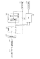
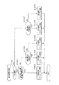
ここで、乱数生成器180,スタート検出センサ71a及びCPU151の接続関係を、図10のブロック図に基づいてより詳細に説明する。   Here, the connection relationship among the random number generator 180, the start detection sensor 71a, and the CPU 151 will be described in more detail based on the block diagram of FIG.

乱数生成器180の入力側には、7.915MHzの所定周波数の矩形波(第2クロック信号)を出力する第2クロック回路181と、当該第2クロック回路181を監視するための監視回路182が接続されている。乱数生成器180の出力側には、CPU151が接続されている。   On the input side of the random number generator 180, a second clock circuit 181 that outputs a rectangular wave (second clock signal) having a predetermined frequency of 7.915 MHz and a monitoring circuit 182 for monitoring the second clock circuit 181 are provided. It is connected. A CPU 151 is connected to the output side of the random number generator 180.

乱数生成器180は、カウンタ180aとラッチ回路180bを有するハードウェアである。カウンタ180aは、16ビットのフリーランカウンタであり、0〜65535の範囲内で順に1ずつ加算されると共に、最大値(つまり65535)に達した後0に戻る構成となっている。カウンタ180aには第2クロック回路181が接続されており、当該第2クロック回路181からの第2クロック信号が入力されると、カウンタ180aのカウント値が更新されるようになっている。ラッチ回路180bは、複数のDフリップフロップ回路を組み合わせて構成されており、カウンタ180aのカウント値をラッチ(保持)できるようになっている。ラッチ回路180bには監視回路182が接続されており、当該監視回路182からのラッチ信号が入力されると、そのタイミングにおけるカウンタ180aのカウント値がラッチ回路180bにラッチされ、ラッチされたカウント値が乱数としてCPU151に対して出力されるようになっている。   The random number generator 180 is hardware having a counter 180a and a latch circuit 180b. The counter 180a is a 16-bit free-run counter that is incremented by 1 within the range of 0 to 65535, and returns to 0 after reaching the maximum value (that is, 65535). A second clock circuit 181 is connected to the counter 180a, and when the second clock signal from the second clock circuit 181 is input, the count value of the counter 180a is updated. The latch circuit 180b is configured by combining a plurality of D flip-flop circuits, and can latch (hold) the count value of the counter 180a. A monitoring circuit 182 is connected to the latch circuit 180b. When a latch signal from the monitoring circuit 182 is input, the count value of the counter 180a at that timing is latched in the latch circuit 180b, and the latched count value is A random number is output to the CPU 151.

監視回路182は、Dフリップフロップ回路により構成されている。すなわち、監視回路182は、入力端子としてデータ端子(D端子)とクロック端子(CLK端子)を有し、出力端子として正論理出力端子(Q端子)と負論理出力端子(Qバー端子)を有している。D端子には、スタート検出センサ71aが波形整形回路183及び入出力ポート155を介して接続されており、CLK端子には、第2クロック回路181が反転器184を介して接続されている。また、Q端子には、乱数生成器180のラッチ回路182が接続されており、Qバー端子には、CPU151が接続されている。   The monitoring circuit 182 is composed of a D flip-flop circuit. That is, the monitoring circuit 182 has a data terminal (D terminal) and a clock terminal (CLK terminal) as input terminals, and a positive logic output terminal (Q terminal) and a negative logic output terminal (Q bar terminal) as output terminals. is doing. A start detection sensor 71 a is connected to the D terminal via a waveform shaping circuit 183 and an input / output port 155, and a second clock circuit 181 is connected to the CLK terminal via an inverter 184. Further, the latch circuit 182 of the random number generator 180 is connected to the Q terminal, and the CPU 151 is connected to the Q bar terminal.

スタート検出センサ71aは、スタートレバー71が操作されると操作信号を出力する。より詳しくは、スタート検出センサ71aは、スタートレバー71が初期位置から移動した場合に操作信号を出力し、スタートレバー71が初期位置に復帰した場合に操作信号の出力を停止する。波形整形回路183は、シュミットトリガ回路により構成されている。波形整形回路183には閾値が設定されており、波形整形回路183は、スタート検出センサ71aから出力された操作信号が電圧上昇側閾値よりも大きくなった場合に検出信号を監視回路182に対して出力し、操作信号が電圧降下側閾値よりも小さくなった場合に検出信号の出力を停止する。つまり、波形整形回路183とは、スタート検出センサ71aから出力される操作信号のなまり(立ち上がり遅れ及び立ち下がり遅れ)を整形するための回路である。なお、波形整形回路183は、入出力ポート155と監視回路182との間に接続されていても良く、波形整形回路183を主制御装置131上に設けることも可能である。   The start detection sensor 71a outputs an operation signal when the start lever 71 is operated. More specifically, the start detection sensor 71a outputs an operation signal when the start lever 71 moves from the initial position, and stops outputting the operation signal when the start lever 71 returns to the initial position. The waveform shaping circuit 183 is configured by a Schmitt trigger circuit. A threshold is set in the waveform shaping circuit 183, and the waveform shaping circuit 183 sends a detection signal to the monitoring circuit 182 when the operation signal output from the start detection sensor 71a is larger than the voltage increase side threshold. The output of the detection signal is stopped when the operation signal is smaller than the voltage drop side threshold. That is, the waveform shaping circuit 183 is a circuit for shaping the rounds (rise delay and fall delay) of the operation signal output from the start detection sensor 71a. The waveform shaping circuit 183 may be connected between the input / output port 155 and the monitoring circuit 182, and the waveform shaping circuit 183 may be provided on the main controller 131.

監視回路182は、反転された第2クロック信号(反転クロック信号)がCLK端子に入力されたタイミング(より詳しくは反転クロック信号の立ち上がりのタイミング)で操作信号(より詳しくは波形整形回路183からの検出信号)が入力されている場合、乱数生成器180に対してラッチ信号を出力すると共にCPU151に対して開始信号を出力する。これらラッチ信号及び開始信号は、反転クロック信号がCLK端子に入力されたタイミングで操作信号が入力されていない状態となるまで継続出力される。換言すれば、監視回路182は、反転クロック信号がCLK端子に入力されるまで操作信号の入力状態を保持しているとも言える。   The monitoring circuit 182 operates the operation signal (more specifically, from the waveform shaping circuit 183 at the timing when the inverted second clock signal (inverted clock signal) is input to the CLK terminal (more specifically, the rising timing of the inverted clock signal). When a detection signal) is input, a latch signal is output to the random number generator 180 and a start signal is output to the CPU 151. These latch signal and start signal are continuously output until the operation signal is not input at the timing when the inverted clock signal is input to the CLK terminal. In other words, it can be said that the monitoring circuit 182 holds the input state of the operation signal until the inverted clock signal is input to the CLK terminal.

CPU151は、乱数生成器180のラッチ回路180bと接続されると共に、監視回路182のQバー端子と接続されている。また、CPU151には、第1クロック信号を出力する第1クロック回路154が接続されている。第1クロック回路154は、8.000MHzの所定周波数の矩形波を出力するものであり、第2クロック回路181と同期しないように構成されている。CPU151は、第1クロック信号が入力された場合に各種動作を行うようになっている。例えば、第1クロック信号の入力に基づいて開始信号の入力有無を判別し、開始信号が入力されている場合にはラッチ回路180bにラッチされたカウント値を乱数として取得するようになっている。開始信号の入力有無の判別についてより詳細に説明すると、CPU151は、監視回路182のQバー端子と接続されているため、Qバー端子からの入力信号がHレベルからLレベルに切り替っている場合に開始信号が入力されたと判別している。   The CPU 151 is connected to the latch circuit 180 b of the random number generator 180 and to the Q bar terminal of the monitoring circuit 182. The CPU 151 is connected to a first clock circuit 154 that outputs a first clock signal. The first clock circuit 154 outputs a rectangular wave having a predetermined frequency of 8.000 MHz and is configured not to synchronize with the second clock circuit 181. The CPU 151 performs various operations when the first clock signal is input. For example, it is determined whether or not a start signal is input based on the input of the first clock signal, and when the start signal is input, the count value latched in the latch circuit 180b is acquired as a random number. The determination of whether or not the start signal is input will be described in more detail. Since the CPU 151 is connected to the Q bar terminal of the monitoring circuit 182, the input signal from the Q bar terminal is switched from the H level to the L level. It is determined that a start signal has been input.

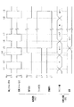
次に、乱数生成器180及び監視回路182の動作を図11のタイミングチャートに基づき説明する。   Next, operations of the random number generator 180 and the monitoring circuit 182 will be described based on the timing chart of FIG.

t1のタイミングで第2クロック回路181から出力される信号がLレベルからHレベルに立ち上がる、すなわち第2クロック信号が出力有り状態(第2クロック回路から出力される信号がHレベルの状態)に切り替ると、乱数生成器180では、カウンタ180aのカウント値が更新されてnとなる。nは0〜65535のいずれかの値である。また、監視回路182のCLK端子には第2クロック回路181が反転器184を介して接続されているため、監視回路182では、CLK端子に入力される信号がタイミングt1においてHレベルからLレベルに立ち下がり、反転クロック信号が入力無し状態に切り替る。   The signal output from the second clock circuit 181 rises from the L level to the H level at the timing t1, that is, the second clock signal is switched to the output present state (the signal output from the second clock circuit is the H level state). Then, in the random number generator 180, the count value of the counter 180a is updated to n. n is any value from 0 to 65535. In addition, since the second clock circuit 181 is connected to the CLK terminal of the monitoring circuit 182 via the inverter 184, in the monitoring circuit 182, the signal input to the CLK terminal changes from the H level to the L level at timing t1. Falling, inverted clock signal switches to no input state.

t2のタイミングで第2クロック回路181から出力される信号がHレベルからLレベルに立ち下がる、すなわち第2クロック信号が出力無し状態(第2クロック回路から出力される信号がLレベルの状態)に切り替ると、監視回路182では、CLK端子に入力される信号がLレベルからHレベルに立ち上がり、反転クロック信号が入力有り状態に切り替る。このとき、乱数生成器180では、カウンタ180aのカウント値が更新されることはなく、カウント値はnのままである。   The signal output from the second clock circuit 181 falls from the H level to the L level at the timing t2, that is, the second clock signal is not output (the signal output from the second clock circuit is in the L level). When the switching is performed, the monitoring circuit 182 causes the signal input to the CLK terminal to rise from the L level to the H level, and the inverted clock signal is switched to the input presence state. At this time, in the random number generator 180, the count value of the counter 180a is not updated, and the count value remains n.

監視回路182は、反転クロック信号が入力有り状態に切り替った場合、そのときにD端子に入力されている操作信号の入力状態に応じた信号を、Q端子及びQバー端子から出力する。タイミングt2では操作信号(Hレベルの検出信号)が入力されていないため、Q端子及びQバー端子からラッチ信号及び開始信号を出力しない。なお、開始信号はQバー端子(負論理出力端子)から出力されるため、開始信号に限りHレベルではなくLレベルの信号が開始信号となる。   When the inverted clock signal is switched to the input presence state, the monitoring circuit 182 outputs a signal corresponding to the input state of the operation signal input to the D terminal at that time from the Q terminal and the Q bar terminal. Since the operation signal (H level detection signal) is not input at the timing t2, the latch signal and the start signal are not output from the Q terminal and the Q bar terminal. Since the start signal is output from the Q bar terminal (negative logic output terminal), only the start signal is an L level signal instead of the H level.

その後、t3のタイミングで第2クロック信号が出力有り状態に切り替ると、乱数生成器180では、カウンタ180aのカウント値が更新されてn+1となる。このように、乱数生成器180では、第2クロック信号が出力無し状態から出力有り状態に切り替るタイミングでカウント値の更新が順次行われる。   After that, when the second clock signal is switched to the output enabled state at the timing of t3, the random number generator 180 updates the count value of the counter 180a to n + 1. As described above, the random number generator 180 sequentially updates the count value at the timing when the second clock signal is switched from the non-output state to the output state.

t4のタイミングでスタートレバー71が操作された場合、監視回路182のD端子に入力されている信号がLレベルからHレベルに立ち上がり、操作信号が入力有り状態に切り替る。但し、かかるタイミングt4では反転クロック信号が入力無し状態のため、ラッチ信号及び開始信号は出力無し状態のままである。   When the start lever 71 is operated at the timing t4, the signal input to the D terminal of the monitoring circuit 182 rises from the L level to the H level, and the operation signal is switched to the input presence state. However, since the inverted clock signal is not input at the timing t4, the latch signal and the start signal remain in the no output state.

t5のタイミングで反転クロック信号が入力無し状態から入力有り状態に切り替った場合、監視回路182では、D端子に操作信号が入力されているため、Q端子からの出力信号をLレベルからHレベルに立ち上げると共に、Qバー端子からの出力信号をHレベルからLレベルに立ち下げる。この結果、かかるタイミングt5で開始信号とラッチ信号が出力無し状態から出力有り状態に切り替る。乱数生成器180では、監視回路182からのラッチ信号が入力無し状態から入力有り状態に切り替ったことに伴い、このときのカウンタ180aのカウント値n+1をラッチ回路180bにラッチする。つまり、t4のタイミングでスタートレバー71が操作された場合、タイミングt4ではなくタイミングt5においてカウント値n+1が乱数として取得される。   When the inverted clock signal is switched from the no-input state to the input-present state at the timing t5, since the operation signal is input to the D terminal in the monitoring circuit 182, the output signal from the Q terminal is changed from the L level to the H level. At the same time, the output signal from the Q bar terminal falls from the H level to the L level. As a result, at the timing t5, the start signal and the latch signal are switched from the no output state to the output present state. The random number generator 180 latches the count value n + 1 of the counter 180a at this time in the latch circuit 180b as the latch signal from the monitoring circuit 182 switches from the no-input state to the input-present state. That is, when the start lever 71 is operated at the timing t4, the count value n + 1 is acquired as a random number not at the timing t4 but at the timing t5.

t6のタイミングでは、反転クロック信号が入力有り状態から入力無し状態に切り替るが、ラッチ信号及び開始信号の出力状態が変更されることはなく、そのまま出力有り状態が保持される。つまり、反転クロック信号が入力有り状態から入力無し状態に切り替ったとしても、ラッチ信号と開始信号は共に出力有り状態のまま保持される。   At the timing of t6, the inverted clock signal is switched from the input present state to the no input state, but the output state of the latch signal and the start signal is not changed, and the output present state is maintained as it is. In other words, even if the inverted clock signal is switched from the input state to the no input state, both the latch signal and the start signal are held in the output state.

その後、t7のタイミングで反転クロック信号が入力無し状態から入力有り状態に切り替ると、かかるタイミングにおける操作信号の入力状態に応じたラッチ信号と開始信号が出力される。t7のタイミングでは操作信号が入力有り状態のため、出力有り状態のままラッチ信号と開始信号が継続して出力される。   Thereafter, when the inverted clock signal is switched from the non-input state to the input state at the timing t7, a latch signal and a start signal corresponding to the operation signal input state at the timing are output. Since the operation signal is in the input presence state at the timing t7, the latch signal and the start signal are continuously output in the output presence state.

ここで、乱数生成器180において、カウンタ180aのカウント値の更新は第2クロック信号が入力無し状態から入力有り状態に切り替るタイミング(t1,t3,t6等)で行われ、ラッチ回路180bにおけるカウント値のラッチはラッチ信号が入力無し状態から入力有り状態に切り替るタイミング(t5)で行われる。ラッチ信号が入力無し状態から入力有り状態に切り替るタイミングは、反転クロック信号が入力無し状態から入力有り状態に切り替るタイミング、すなわち第2クロック信号が入力有り状態から入力無し状態に切り替るタイミングである。つまり、乱数生成器180では、第2クロック信号が入力無し状態から入力有り状態に切り替るタイミングでカウント値の更新が行われ、第2クロック信号が入力有り状態から入力無し状態に切り替るタイミングでカウント値のラッチが行われる。かかる構成とすることにより、カウント値の更新タイミングとカウント値のラッチタイミングが同じタイミングとなることを回避でき、カウント値が更新されている最中にラッチタイミングがやってきてカウント値を正常にラッチできない不具合が生じることを回避できる。   Here, in the random number generator 180, the count value of the counter 180a is updated at the timing (t1, t3, t6, etc.) when the second clock signal switches from the no-input state to the input-present state, and the count in the latch circuit 180b. The value is latched at a timing (t5) when the latch signal switches from the non-input state to the input state. The timing at which the latch signal switches from the no input state to the input present state is the timing at which the inverted clock signal switches from the no input state to the input present state, that is, the timing at which the second clock signal switches from the input present state to the no input state. is there. That is, in the random number generator 180, the count value is updated at the timing when the second clock signal switches from the no-input state to the input-present state, and at the timing when the second clock signal switches from the input-present state to the no-input state. The count value is latched. By adopting such a configuration, it is possible to prevent the count value update timing and the count value latch timing from being the same, and the latch timing comes while the count value is being updated, and the count value cannot be normally latched. It is possible to avoid problems.

タイミングt8でスタートレバー71が初期位置に復帰すると、監視回路182に入力されている操作信号が入力有り状態から入力無し状態に切り替る。タイミングt8は反転クロック信号が入力有り状態から入力無し状態に切り替るタイミングのため、かかるタイミングではラッチ信号及び開始信号の出力状態は変化しない。そして、反転クロック信号が入力無し状態から入力有り状態に切り替るタイミングt9で操作信号が入力されていないことが検知され、ラッチ信号と開始信号が共に出力有り状態から出力無し状態に切り替る。なお、反転クロック信号が入力有り状態下(例えばタイミングt8<タイミングt<タイミングt9)で操作信号が入力有り状態から入力無し状態に切り替った場合、或いは反転クロック信号が入力無し状態下(例えばタイミングt7<タイミングt<タイミングt8)で操作信号が入力有り状態から入力無し状態に切り替った場合であっても、タイミングt9でラッチ信号と開始信号が共に出力有り状態から出力無し状態に切り替る。   When the start lever 71 returns to the initial position at the timing t8, the operation signal input to the monitoring circuit 182 switches from the input present state to the no input state. Since the timing t8 is a timing at which the inverted clock signal switches from the input present state to the no input state, the output state of the latch signal and the start signal does not change at this timing. Then, it is detected that the operation signal is not input at a timing t9 when the inverted clock signal is switched from the no-input state to the input-present state, and both the latch signal and the start signal are switched from the output-present state to the no-output state. It should be noted that when the inverted clock signal is in the input present state (for example, timing t8 <timing t <timing t9), the operation signal is switched from the input present state to the no input state, or the inverted clock signal is in the no input state (for example, timing Even if the operation signal is switched from the input present state to the no input state at t7 <timing t <timing t8), both the latch signal and the start signal are switched from the output present state to the no output state at timing t9.

ちなみに、操作信号が入力されるタイミングを常時把握するのではなく反転クロック信号が入力されるタイミングで把握する構成の場合、1の反転クロック信号が入力された後に操作信号が入力有り状態に切り替り、次の反転クロック信号が入力されるまでの間に操作信号が入力無し状態に切り替ると、スタートレバー71の操作を正確に把握できないという可能性が考えられる。ところが、本スロットマシン10におけるスタートレバー71は、手が離れたあと初期位置に復帰するまでに数10msecを有するように構成されており、スタートレバー71が操作されると少なくとも数10msecは操作信号が監視回路182に入力されるようになっている。また、第2クロック回路181から出力される第2クロック信号のクロック周波数は7.915MHzであり、その周期は約126nsecである。つまり、監視回路182において反転クロック信号が入力される周期は、操作信号が入力有り状態に切り替ってから入力無し状態に切り替るまでに要する時間間隔と比して十分に短い。したがって、スタートレバー検出センサ71aから操作信号が出力されたにも関わらず監視回路182において前記操作信号が読み飛ばされるという不具合が生じることを回避できる。   By the way, when the configuration is such that the timing at which the operation signal is inputted is not always grasped but at the timing at which the inverted clock signal is inputted, the operation signal is switched to the input present state after the one inverted clock signal is inputted. If the operation signal is switched to the no-input state until the next inverted clock signal is input, there is a possibility that the operation of the start lever 71 cannot be accurately grasped. However, the start lever 71 in the slot machine 10 is configured to have several tens of milliseconds until the hand returns and returns to the initial position. When the start lever 71 is operated, the operation signal is at least several tens of milliseconds. The signal is input to the monitoring circuit 182. The clock frequency of the second clock signal output from the second clock circuit 181 is 7.915 MHz, and the period is about 126 nsec. In other words, the period in which the inverted clock signal is input in the monitoring circuit 182 is sufficiently shorter than the time interval required for the operation signal to switch from the input state to the input state. Therefore, it is possible to avoid a problem that the operation signal is skipped in the monitoring circuit 182 even though the operation signal is output from the start lever detection sensor 71a.

続いて、主制御装置131内のCPU151により実行される各制御処理を図12〜図30のフローチャートを参照しながら説明する。CPU151は、第1クロック回路154から第1クロック信号が入力されることに基づいて各種処理を行う。かかるCPU151の処理としては大別して、電源投入に伴い起動されるメイン処理と、定期的に(本実施の形態では1.49msec周期で)起動されるタイマ割込み処理と、NMI端子(ノンマスカブル端子)への停電信号の入力により起動されるNMI割込み処理とがあり、説明の便宜上、はじめにNMI割込み処理とタイマ割込み処理とを説明し、その後メイン処理を説明する。   Next, each control process executed by the CPU 151 in the main controller 131 will be described with reference to the flowcharts of FIGS. The CPU 151 performs various processes based on the input of the first clock signal from the first clock circuit 154. The processing of the CPU 151 is broadly divided into a main processing that is started when the power is turned on, a timer interrupt processing that is started periodically (in a cycle of 1.49 msec in the present embodiment), and an NMI terminal (non-maskable terminal). For convenience of explanation, the NMI interrupt process and the timer interrupt process will be described first, and then the main process will be described.

図12はNMI割込み処理の一例を示すフローチャートである。停電の発生などによって電源が遮断されると、電源装置161の停電監視回路161bでは停電信号が生成され、主制御装置131に対して出力される。NMI端子を介して停電信号を受信した主制御装置131では、NMI割込み処理が実行される。   FIG. 12 is a flowchart showing an example of the NMI interrupt process. When the power is shut off due to the occurrence of a power failure or the like, the power failure monitoring circuit 161b of the power supply device 161 generates a power failure signal and outputs it to the main controller 131. In the main controller 131 that has received the power failure signal via the NMI terminal, NMI interrupt processing is executed.

NMI割込み処理では、まずステップS101において、CPU151内に設けられた使用レジスタのデータをRAM153内に設けられたバックアップエリアに退避させる。続いて、ステップS102では、停電フラグをRAM153内に設けられた停電フラグ格納エリアにセットする。その後、ステップS103にてRAM153のバックアップエリアに退避させたデータを再びCPU151の使用レジスタに復帰させる。この復帰処理でNMI割込み処理が終了する。なお、CPU151の使用レジスタのデータを破壊せずに停電フラグのセット処理が可能な場合には、バックアップエリアへの退避および復帰処理を省くことができる。   In the NMI interrupt processing, first, in step S 101, the data of the used register provided in the CPU 151 is saved in the backup area provided in the RAM 153. Subsequently, in step S102, the power failure flag is set in a power failure flag storage area provided in the RAM 153. Thereafter, the data saved in the backup area of the RAM 153 in step S103 is restored to the use register of the CPU 151 again. With this return processing, the NMI interrupt processing ends. If the power failure flag can be set without destroying the data in the register used by the CPU 151, the saving and restoring processing to the backup area can be omitted.

図13は、主制御装置131で定期的に実行されるタイマ割込み処理のフローチャートであり、主制御装置131のCPU151により例えば1.49msecごとにタイマ割込みが発生する。   FIG. 13 is a flowchart of timer interrupt processing periodically executed by the main control device 131. A timer interrupt is generated by the CPU 151 of the main control device 131 every 1.49 msec, for example.

先ず、ステップS201に示すレジスタ退避処理では、後述する通常処理で使用しているCPU151内の全レジスタの値をRAM153のバックアップエリアに退避させる。ステップS202では停電フラグがセットされているか否かを確認し、停電フラグがセットされているときにはステップS203に進み、停電時処理を実行する。   First, in the register saving process shown in step S201, the values of all the registers in the CPU 151 used in the normal process described later are saved in the backup area of the RAM 153. In step S202, it is confirmed whether or not a power failure flag is set. If the power failure flag is set, the process proceeds to step S203, and a power failure process is executed.

ここで、停電時処理について図14を用いて説明する。この停電時処理は、タイマ割込み処理のうち特にレジスタ退避処理の直後に行われるため、その他の割込み処理を中断することなく実行できる。従って、例えば各種コマンドの送信処理中、スイッチの状態(オンオフ)の読み込み処理中などのように、それぞれの処理に割り込んでこの停電時処理が実行されることはなく、かかるタイミングで実行されることをも考慮した停電時処理のプログラムを作成する必要がなくなる。これにより停電時処理用の処理プログラムを簡略化してプログラム容量を削減できる。なお、このことは後述する復電時処理用の処理プログラムについても同様である。   Here, the power failure process will be described with reference to FIG. Since the power failure process is performed immediately after the register saving process in the timer interrupt process, other interrupt processes can be executed without interruption. Therefore, for example, during the process of transmitting various commands, during the process of reading the switch state (on / off), the process at the time of power failure is not executed by interrupting each process. It is no longer necessary to create a power failure processing program that also takes into account This simplifies the processing program for power failure processing and reduces the program capacity. This also applies to a processing program for power recovery processing described later.

ステップS301では、コマンド送信が終了しているか否かを判定する。送信が終了していない場合には本処理を終了してタイマ割込み処理に復帰し、コマンド送信を終了させる。このように停電時処理の初期段階でコマンドの送信が完了しているか否かを判断し、送信が未完であるときには送信処理を優先し、単位コマンドの送信処理終了後に停電時処理を実行する構成とすることにより、コマンドの送信途中で停電時処理が実行されることをも考慮した停電時処理プログラムを構築する必要がなくなる。その結果停電時処理プログラムを簡略化してROM152の小容量化を図ることができる実益を有する。   In step S301, it is determined whether command transmission has been completed. If the transmission has not been completed, this process is terminated and the process returns to the timer interrupt process to terminate the command transmission. In this way, it is determined whether or not the command transmission is completed at the initial stage of the power failure process, the transmission process is prioritized when the transmission is incomplete, and the power failure process is executed after the unit command transmission process is completed. By doing so, it is no longer necessary to construct a power failure processing program that takes into account that power failure processing is executed during command transmission. As a result, the power failure processing program can be simplified and the ROM 152 can be reduced in capacity.

ステップS301がYES、すなわちコマンドの送信が完了している場合には、ステップS302に進み、CPU151のスタックポインタの値をRAM153内のバックアップエリアに保存する。その後ステップS303では、停止処理として後述するRAM判定値をクリアすると共に入出力ポート155における出力ポートの出力状態をクリアし、図示しない全てのアクチュエータをオフ状態にする。ステップS304では、RAM判定値を算出し、バックアップエリアに保存する。RAM判定値とは、具体的にはRAM153の作業領域アドレスにおけるチェックサムの2の補数である。RAM判定値をバックアップエリアに保存することにより、RAM153のチェックサムは0となる。RAM153のチェックサムを0とすることにより、ステップS305においてそれ以後のRAMアクセスを禁止する。その後は、電源が完全に遮断して処理が実行できなくなるのに備え、無限ループに入る。なお、例えばノイズ等に起因して停電フラグが誤ってセットされる場合を考慮し、無限ループに入るまでは停電信号が出力されているか否かを確認する。停電信号が出力されていなければ停電状態から復旧したこととなるため、RAM153への書き込みを許可すると共に停電フラグをリセットし、タイマ割込み処理に復帰する。停電信号の出力が継続してなされていれば、そのまま無限ループに入る。ちなみに、詳細な説明は省略するが、無限ループ下においても停電信号が出力されているか否かを確認しており、停電信号が出力されなくなった場合には後述するメイン処理に移行する。   If step S301 is YES, that is, if the command transmission is completed, the process proceeds to step S302, and the value of the stack pointer of the CPU 151 is stored in the backup area in the RAM 153. Thereafter, in step S303, a RAM determination value, which will be described later, is cleared as a stop process and the output state of the output port in the input / output port 155 is cleared, and all actuators (not shown) are turned off. In step S304, a RAM determination value is calculated and stored in the backup area. The RAM determination value is specifically a 2's complement of the checksum at the work area address of the RAM 153. By storing the RAM determination value in the backup area, the checksum of the RAM 153 becomes zero. By setting the checksum of the RAM 153 to 0, subsequent RAM access is prohibited in step S305. After that, an infinite loop is entered in preparation for the case where the power supply is completely shut down and processing cannot be executed. In consideration of, for example, a case where the power failure flag is erroneously set due to noise or the like, it is confirmed whether or not a power failure signal is output until the infinite loop is entered. If the power failure signal is not output, it means that the power failure state has been recovered. Therefore, writing to the RAM 153 is permitted, the power failure flag is reset, and the process returns to the timer interrupt process. If the power outage signal is continuously output, the infinite loop is entered. Incidentally, although detailed description is omitted, it is confirmed whether or not a power failure signal is output even under an infinite loop, and when the power failure signal is not output, the processing shifts to a main process described later.

なお、電源装置161の電源部161aは、上述したNMI割込み処理及び停電時処理を実行するのに十分な時間、制御系の駆動電圧として使用される安定化電圧(5ボルト)の出力が保持されるように構成されている。本実施形態では、30msecの間、駆動電圧が出力され続けるようになっている。   The power supply unit 161a of the power supply device 161 holds the output of the stabilization voltage (5 volts) used as the drive voltage for the control system for a time sufficient to execute the above-described NMI interrupt processing and power failure processing. It is comprised so that. In the present embodiment, the drive voltage is continuously output for 30 msec.

タイマ割込み処理の説明に戻り、ステップS202にて停電フラグがセットされていない場合には、ステップS204以降の各種処理を行う。   Returning to the description of the timer interrupt process, if the power failure flag is not set in step S202, various processes after step S204 are performed.

すなわち、ステップS204では、誤動作の発生を監視するためのウォッチドッグタイマの値を初期化するウォッチドッグタイマのクリア処理を行う。ステップS205では、CPU151自身に対して次回のタイマ割込みを設定可能とする割込み終了宣言処理を行う。ステップS206では、各リール42L,42M,42Rを回転させるために、それぞれの回胴駆動モータであるステッピングモータ61L〜61Rを駆動させるステッピングモータ制御処理を行う。ステップS207では、入出力ポート155に接続された投入メダル検出センサ75aや払出検出センサ91a等の各種センサ(図9参照)の状態を読み込むと共に、読み込み結果が正常か否かを監視するセンサ監視処理を行う。また、センサ監視処理では、監視回路182からの開始信号が入力されているか否か、すなわち監視回路182からのLレベルの信号が入力されているか否かを判別する。そして、開始信号が入力されている場合には開始フラグをセットし、開始信号が入力されていない場合には開始フラグをクリアする。ステップS208では、各カウンタやタイマの値を減算するタイマ演算処理を行う。ステップS209では、メダルのベット数や、払出枚数をカウントした結果を外部集中端子板171へ出力するカウンタ処理を行う。   That is, in step S204, a watchdog timer clear process for initializing the value of the watchdog timer for monitoring the occurrence of malfunction is performed. In step S205, an interrupt end declaration process is performed to enable the next timer interrupt to be set for the CPU 151 itself. In step S206, in order to rotate the reels 42L, 42M, and 42R, a stepping motor control process for driving the stepping motors 61L to 61R, which are the respective rotary drive motors, is performed. In step S207, sensor monitoring processing for reading the states of various sensors (see FIG. 9) such as the inserted medal detection sensor 75a and the payout detection sensor 91a connected to the input / output port 155 and monitoring whether the read result is normal or not. I do. In the sensor monitoring process, it is determined whether or not a start signal from the monitoring circuit 182 is input, that is, whether or not an L level signal from the monitoring circuit 182 is input. When the start signal is input, the start flag is set. When the start signal is not input, the start flag is cleared. In step S208, timer calculation processing for subtracting the value of each counter or timer is performed. In step S209, a counter process for outputting the bet number of medals and the result of counting the number of payouts to the external concentration terminal board 171 is performed.

ステップS210では、後述する開始コマンドや状態コマンド等の各種コマンドを表示制御装置111へ送信するコマンド出力処理を行う。ステップS211では、クレジット表示部35、残獲得枚数表示部36及び獲得枚数表示部37にそれぞれ表示されるセグメントデータを設定するセグメントデータ設定処理を行う。ステップS212では、セグメントデータ設定処理で設定されたセグメントデータを各表示部35〜37に供給して該当する数字、記号などを表示するセグメントデータ表示処理を行う。ステップS213では、入出力ポート155からI/O装置に対応するデータを出力するポート出力処理を行う。ステップS214では、先のステップS201にてバックアップエリアに退避させた各レジスタの値をそれぞれCPU151内の対応するレジスタに復帰させる。その後ステップS215にて次回のタイマ割込みを許可する割込み許可処理を行い、この一連のタイマ割込み処理を終了する。   In step S210, command output processing for transmitting various commands such as a start command and a status command to be described later to the display control device 111 is performed. In step S211, segment data setting processing for setting segment data to be displayed on the credit display unit 35, the remaining acquired number display unit 36, and the acquired number display unit 37 is performed. In step S212, segment data set processing in the segment data setting processing is supplied to the display units 35 to 37, and segment data display processing for displaying corresponding numbers, symbols, and the like is performed. In step S213, port output processing for outputting data corresponding to the I / O device from the input / output port 155 is performed. In step S214, the value of each register saved in the backup area in the previous step S201 is restored to the corresponding register in the CPU 151. Thereafter, in step S215, an interrupt permission process for permitting the next timer interrupt is performed, and this series of timer interrupt processes is terminated.

図15は電源投入後に実行される主制御装置131でのメイン処理を示すフローチャートである。メイン処理は、停電からの復旧や電源スイッチ122のオン操作によって電源が投入された際に実行される。   FIG. 15 is a flowchart showing a main process in the main controller 131 that is executed after the power is turned on. The main process is executed when the power is turned on by recovery from a power failure or by turning on the power switch 122.

先ずステップS401では、初期化処理として、スタックポインタの値をCPU151内に設定すると共に、割込み処理を許可する割込みモードを設定し、その後CPU151内のレジスタ群や、I/O装置等に対する各種の設定などを行う。   First, in step S401, as initialization processing, the value of the stack pointer is set in the CPU 151, and an interrupt mode that permits interrupt processing is set. Thereafter, various settings for the register group in the CPU 151, the I / O device, and the like are set. Etc.

これらの初期化処理が終了すると、ステップS402では設定キーが設定キー挿入孔124に挿入されてON操作されているか否か、より詳しくは設定キー検出センサ124aからON信号を受信しているか否かを判定する。設定キーのON操作がなされている場合にはステップS403に進み、強制的RAMクリア処理としてRAM153に記憶されたデータを全てクリアする。続くステップS404では当選確率設定処理を行う。   When these initialization processes are completed, in step S402, whether or not the setting key is inserted into the setting key insertion hole 124 and is turned ON, more specifically, whether or not the ON signal is received from the setting key detection sensor 124a. Determine. If the setting key has been turned ON, the process proceeds to step S403, and all data stored in the RAM 153 is cleared as a forced RAM clear process. In subsequent step S404, a winning probability setting process is performed.

ここで、当選確率設定処理について図16を用いて説明する。スロットマシン10には、「設定1」から「設定6」まで6段階の当選確率が予め用意されており、当選確率設定処理とは、いずれの当選確率に基づいて内部処理を実行させるのかを設定するための処理である。   Here, the winning probability setting process will be described with reference to FIG. The slot machine 10 is prepared in advance with six stages of winning probabilities from “Setting 1” to “Setting 6”, and the winning probability setting process sets which of the winning probabilities is used to execute internal processing. It is a process to do.

ステップS501では次回のタイマ割込みを許可する。その後、ステップS502にて現在の設定値を読み込むと共に、ステップS503では現在の設定値をクレジット表示部35に表示する。但し、設定キーが挿入されてON操作された直後の処理では、先の強制的RAMクリア処理によりRAM153のデータがクリアされているため、クレジット表示部35に表示される設定値は「1」である。   In step S501, the next timer interrupt is permitted. Thereafter, the current set value is read in step S502, and the current set value is displayed on the credit display unit 35 in step S503. However, in the process immediately after the setting key is inserted and turned ON, the data in the RAM 153 is cleared by the previous forced RAM clear process, so the set value displayed on the credit display unit 35 is “1”. is there.

ステップS504ではスタートレバー71が操作されたか否かを判定し、操作されていない場合にはステップS505〜ステップS506に示す設定更新処理を行う。ステップS505では、リセットスイッチ123が操作されたか否かを判定する。リセットスイッチ123が操作されていない場合にはそのままステップS503に戻り、操作された場合にはステップS506にて設定値を1更新した後にステップS503に戻る。つまり、設定更新処理では、リセットスイッチ123が操作される毎に設定値が1更新され、更新された設定値がクレジット表示部35に表示される。なお、設定値が「6」のときにリセットスイッチ123が操作された場合、設定値は「1」に更新される。   In step S504, it is determined whether or not the start lever 71 is operated. If the start lever 71 is not operated, setting update processing shown in steps S505 to S506 is performed. In step S505, it is determined whether or not the reset switch 123 has been operated. If the reset switch 123 is not operated, the process directly returns to step S503. If the reset switch 123 is operated, the set value is updated by 1 in step S506, and then the process returns to step S503. That is, in the setting update process, every time the reset switch 123 is operated, the setting value is updated by 1, and the updated setting value is displayed on the credit display unit 35. When the reset switch 123 is operated when the set value is “6”, the set value is updated to “1”.

ステップS504にてスタートレバー71が操作された場合には、ステップS507にて設定キーのON操作が継続してなされているか否かを判定する。設定キーのON操作が継続してなされている場合にはそのまま待機し、ON操作が終了された場合にはステップS508にて次回のタイマ割込みを禁止する。その後、ステップS509にて設定値を保存し、ステップS510にてRAM153に記憶された設定値以外のデータをクリアして本処理を終了する。   If the start lever 71 is operated in step S504, it is determined in step S507 whether or not the setting key is continuously turned on. If the ON operation of the setting key is continued, the process waits as it is, and if the ON operation is ended, the next timer interruption is prohibited in step S508. Thereafter, the set value is stored in step S509, data other than the set value stored in the RAM 153 is cleared in step S510, and this process is terminated.

メイン処理の説明に戻り、ステップS404にて当選確率設定処理を行った後には、ステップS405にて遊技に関わる主要な制御を行う通常処理を実行する。   Returning to the description of the main process, after performing the winning probability setting process in step S404, a normal process for performing main control relating to the game is executed in step S405.

一方、ステップS402にて設定キーが挿入されていない場合には、ステップS406以降に示す復電処理を行う。復電処理とは、スロットマシン10の状態を電源遮断前の状態に復帰させる処理である。従って、復電処理では先ずRAM153のデータが正常かどうかを確認する必要がある。   On the other hand, when the setting key is not inserted in step S402, power recovery processing shown in step S406 and subsequent steps is performed. The power recovery process is a process for returning the state of the slot machine 10 to the state before the power is shut off. Therefore, in the power recovery process, it is necessary to first check whether the data in the RAM 153 is normal.

そこで、ステップS406では設定値が正常か否かを判定する。具体的には、設定値が1〜6のいずれかである場合に正常であると判定し、0又は7以上である場合に異常であると判定する。設定値が正常である場合には、ステップS407にて停電フラグがセットされているか否かを確認する。停電フラグがセットされている場合には、さらにステップS408にてRAM判定値が正常であるか否かを確認する。具体的には、RAM153のチェックサムの値を調べ、その値が正常、つまりRAM判定値を加味したチェックサムの値が0か否かを確認する。RAM判定値を加味したチェックサムの値が0である場合、RAM153のデータは正常であると判定する。   Therefore, in step S406, it is determined whether or not the set value is normal. Specifically, when the set value is any one of 1 to 6, it is determined to be normal, and when it is 0 or 7 or more, it is determined to be abnormal. If the set value is normal, it is confirmed in step S407 whether or not a power failure flag is set. If the power failure flag is set, it is further confirmed in step S408 whether or not the RAM determination value is normal. Specifically, the checksum value of the RAM 153 is checked to check whether the value is normal, that is, whether the checksum value including the RAM determination value is 0. If the checksum value including the RAM determination value is 0, it is determined that the data in the RAM 153 is normal.

ステップS408においてRAM判定値が正常であると判定した場合にはステップS409に進み、バックアップエリアに保存されたスタックポインタの値をCPU151のスタックポインタに書き込み、スタックの状態を電源が遮断される前の状態に復帰させる。次に、ステップS410において、復電処理の実行を伝える復電コマンドを表示制御装置111に送信する。その後、ステップS411にて遊技状態として打ち止め及び自動精算設定保存処理を行い、ステップS412にてスタート検出センサ71a等の各種センサの初期化を行う。以上の処理が終了した後、ステップS413にて停電フラグをリセットし、電源遮断前の番地に戻る。具体的には、先に説明したタイマ割込み処理に復帰し、ウォッチドッグタイマクリア処理(ステップS204)が実行されることとなる。   If it is determined in step S408 that the RAM determination value is normal, the process proceeds to step S409, where the stack pointer value stored in the backup area is written into the stack pointer of the CPU 151, and the stack state before the power is shut off. Return to the state. Next, in step S <b> 410, a power recovery command that tells execution of power recovery processing is transmitted to the display control device 111. After that, in step S411, the game state is stopped and automatic settlement setting storage processing is performed, and in step S412, various sensors such as the start detection sensor 71a are initialized. After the above processing is completed, the power failure flag is reset in step S413, and the processing returns to the address before the power is shut off. Specifically, the process returns to the timer interrupt process described above, and the watchdog timer clear process (step S204) is executed.

一方、ステップS406〜ステップS408のいずれかがNO、すなわち、設定値が異常である、電源遮断時にセットされる筈の停電フラグがセットされていない、又はRAM判定値が異常である場合には、RAM153のデータが破壊された可能性が高い。このような場合には、ステップS414〜ステップS416に示す動作禁止処理を行う。動作禁止処理として、先ずステップS414にて次回のタイマ割込み処理を禁止し、ステップS415では入出力ポート155内の全ての出力ポートをクリアすることにより、入出力ポート155に接続された全てのアクチュエータをオフ状態に制御する。その後、ステップS416にてホール管理者等に上部ランプ13等を用いてエラーの発生を報知するエラー報知処理を行う。かかる動作禁止状態は、上述した当選確率設定処理が行われるまで維持される。   On the other hand, if any of step S406 to step S408 is NO, that is, the set value is abnormal, the power failure flag that is set when the power is shut off is not set, or the RAM determination value is abnormal, There is a high possibility that the data in the RAM 153 has been destroyed. In such a case, the operation prohibiting process shown in steps S414 to S416 is performed. As the operation prohibition process, first, the next timer interrupt process is prohibited in step S414, and in step S415, all output ports in the input / output port 155 are cleared, so that all actuators connected to the input / output port 155 are removed. Control to off state. Thereafter, in step S416, an error notification process for notifying the occurrence of an error to the hall manager or the like using the upper lamp 13 or the like is performed. This operation prohibition state is maintained until the above-described winning probability setting process is performed.

次に、遊技に関わる主要な制御を行う通常処理について図17のフローチャートに基づき説明する。   Next, normal processing for performing main control related to the game will be described based on the flowchart of FIG.

先ずステップS601では、次回のタイマ割込みを許可する割込み許可処理を行う。ステップS602では、遊技を可能とするための開始前処理を行う。開始前処理では、打ち止め及び自動精算の設定状態をRAM153に格納し、表示制御装置111等が初期化を終了するまで待機する。表示制御装置111等の初期化が終了した場合、ステップS603〜ステップS612に示す遊技管理処理を行う。   First, in step S601, an interrupt permission process for permitting the next timer interrupt is performed. In step S602, a pre-start process for enabling a game is performed. In the pre-start process, the setting state of stopping and automatic checkout is stored in the RAM 153 and waits until the display control device 111 and the like finish initialization. When initialization of the display control device 111 and the like is completed, game management processing shown in steps S603 to S612 is performed.

遊技管理処理として、ステップS603では、RAM153の遊技情報格納エリア153cに格納されたデータ(例えば前回のゲームで用いた乱数値等)をクリアし、続くステップS604では開始待ち処理を行う。   As the game management process, in step S603, data stored in the game information storage area 153c of the RAM 153 (for example, a random value used in the previous game) is cleared, and in step S604, a start waiting process is performed.

開始待ち処理では、前回のゲームで再遊技入賞が成立したか否かを判定する。再遊技入賞が成立していた場合には、前回のベット数と同数の仮想メダルを自動投入する自動投入処理を行うと共に、投入完了コマンドをセットして開始待ち処理を終了する。ここで、投入完了コマンドとは、自動投入の完了を把握させるべく表示制御装置111に対して送信されるコマンドである。なお、自動投入処理では、クレジット表示部35に表示された仮想メダル数を減じることなく仮想メダルの投入を行う。つまり、前回のゲームで再遊技入賞が成立した場合には、遊技者は所有するメダルを減らすことなく且つメダルを投入することなく今回のゲームを行うことができる。再遊技入賞が成立していなかった場合には、タイマ割込み処理のセンサ監視処理ステップS207にてなされたセンサの読み込み結果に異常が発生していないかを確認するセンサ異常確認処理を行い、異常が発生している場合にはスロットマシン10をエラー状態とすると共にエラーの発生を報知する異常発生時処理を行う。詳細は後述するが、かかるエラー状態はリセットスイッチ123が操作されるまで維持される。センサの読み込み結果が正常である場合には精算スイッチ80が操作されたか否かを判定し、精算スイッチ80が操作された場合には、クレジットされた仮想メダルと同数のメダルを払い出すメダル返却処理を行うと共に精算コマンドをセットする。ここで、精算コマンドとは、クレジットされた仮想メダルの返却を行っていることを把握させるべく表示制御装置111に対して送信されるコマンドである。メダル返却処理の終了後又は精算スイッチ80が操作されていない場合には、メダルの投入又はクレジット投入スイッチ77〜79の操作がなされたか否かを判定し、いずれかが行われた場合には、有効ラインの設定等を行うメダル投入処理を行うと共に、投入コマンドをセットして開始待ち処理を終了する。ここで、投入コマンドとは、ベット操作がなされたことを把握させるべく表示制御装置111に対して送信されるコマンドである。   In the start waiting process, it is determined whether or not a re-game winning is established in the previous game. If a re-game winning is established, an automatic insertion process for automatically inserting the same number of virtual medals as the previous bet number is performed, and an insertion completion command is set to end the start waiting process. Here, the insertion completion command is a command transmitted to the display control device 111 so as to grasp the completion of the automatic insertion. In the automatic insertion process, virtual medals are inserted without reducing the number of virtual medals displayed on the credit display unit 35. That is, when a re-game winning is established in the previous game, the player can play the current game without reducing the number of medals owned and without inserting medals. If the re-game winning is not established, a sensor abnormality confirmation process is performed to check whether an abnormality has occurred in the sensor reading result in the sensor monitoring process step S207 of the timer interruption process. If the error has occurred, the slot machine 10 is put into an error state and an abnormality occurrence process for notifying the occurrence of the error is performed. Although details will be described later, such an error state is maintained until the reset switch 123 is operated. If the sensor reading result is normal, it is determined whether or not the settlement switch 80 has been operated. If the settlement switch 80 has been operated, a medal return process for paying out the same number of medals as the credited virtual medals And set the checkout command. Here, the settlement command is a command transmitted to the display control device 111 so as to grasp that the credited virtual medal is being returned. After completion of the medal return process or when the settlement switch 80 is not operated, it is determined whether or not the medal insertion or the credit insertion switches 77 to 79 are operated. A medal insertion process for setting an effective line is performed, and an insertion command is set to end the start waiting process. Here, the insertion command is a command transmitted to the display control device 111 in order to grasp that a betting operation has been performed.

開始待ち処理の終了後、ステップS605ではメダルのベット数が規定数(本実施形態では3)に達しているか否かを判定し、規定数に達している場合にはさらにステップS606にてスタートレバー71が操作されて開始指令が発生したか否かを判定する。開始指令が発生したか否かの判定は開始フラグのセット有無に基づいて行っており、開始フラグがセットされている場合に開始指令が発生したと判定する。ベット数が規定数に達していない場合又は開始指令が発生していない場合には、ステップS604の開始待ち処理に戻り、当該処理のうちセンサ異常確認処理以降の処理を行う。   After the start waiting process is completed, it is determined in step S605 whether or not the bet number of medals has reached a specified number (3 in the present embodiment). If the specified number has been reached, the start lever is further determined in step S606. It is determined whether 71 is operated and a start command is generated. Whether or not the start command has been generated is determined based on whether or not the start flag is set. When the start flag is set, it is determined that the start command has been generated. If the bet number has not reached the specified number or if no start command has been issued, the process returns to the start wait process in step S604, and the processes after the sensor abnormality confirmation process are performed.

開始指令が発生した場合にはステップS607に進み、メダル通路切替ソレノイド83を非励磁状態に切り替えてベットの受付を禁止し、続くステップS608にて開始コマンドをセットする。ここで、開始コマンドとは、開始指令が発生したことを把握させるべく表示制御装置111に対して送信されるコマンドである。その後、ステップS609の抽選処理、ステップS610のリール制御処理、ステップS611のメダル払出処理、ステップS612のボーナスゲーム処理を順に実行し、ステップS603に戻る。   If a start command is generated, the process proceeds to step S607, where the medal path switching solenoid 83 is switched to a non-excited state to prohibit bet reception, and a start command is set in the subsequent step S608. Here, the start command is a command transmitted to the display control device 111 in order to grasp that a start command has been generated. Thereafter, the lottery process in step S609, the reel control process in step S610, the medal payout process in step S611, and the bonus game process in step S612 are executed in order, and the process returns to step S603.

なお、通常処理では、投入完了コマンド等の各種コマンドをリングバッファにセットするのみであり、表示制御装置111に対してコマンドを送信しない。表示制御装置111へのコマンド送信は、先述したタイマ割込み処理のコマンド出力処理S210にて行われる。   In the normal process, various commands such as the input completion command are only set in the ring buffer, and the command is not transmitted to the display control device 111. The command transmission to the display control device 111 is performed in the command output process S210 of the timer interrupt process described above.

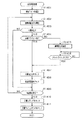
次に、ステップS609の抽選処理について、図18のフローチャートに基づき説明する。   Next, the lottery process in step S609 will be described based on the flowchart of FIG.

ステップS701では、役の当否判定を行う際に用いる乱数を取得する。より具体的には、乱数生成器180は、監視回路182からのラッチ信号が入力されたタイミングでカウント値をラッチするとともに、ラッチしたカウント値をCPU151に対して出力する。CPU151は、その入力されたカウント値を乱数として読み込む。   In step S701, a random number used when determining whether or not the winning combination is determined is acquired. More specifically, the random number generator 180 latches the count value at the timing when the latch signal from the monitoring circuit 182 is input, and outputs the latched count value to the CPU 151. The CPU 151 reads the input count value as a random number.

ここで、タイマ割込み処理におけるステップS208〜ステップS215の一連の処理は、これら一連の処理を行うために必要な時間が、乱数生成器180がカウント値をラッチしてから当該ラッチ結果がCPU151に入力されるまでに要する時間より長くなるように構成されている。かかる構成とすることにより、乱数の取得タイミング(ステップS701の処理を行うタイミング)を、今回のゲームでラッチされたカウント値がCPU151に入力されるタイミングより遅くすることができ、今回のゲームでラッチされたカウント値を確実に乱数として取得することが可能となる。   Here, in the series of processing from step S208 to step S215 in the timer interrupt processing, the time required for performing these series of processing is input to the CPU 151 after the random number generator 180 latches the count value. It is configured so as to be longer than the time required for the operation. With this configuration, the random number acquisition timing (timing for performing the processing of step S701) can be delayed from the timing at which the count value latched in the current game is input to the CPU 151, and is latched in the current game. It is possible to reliably obtain the counted value as a random number.

ステップS702では、スロットマシン10の現在の設定状態や遊技状態等に基づき、当否判定用の抽選テーブルを選択する。ここで、スロットマシン10の設定状態は「設定1」〜「設定6」のいずれかであり、「設定1」のときにBB当選確率が最も低い抽選テーブルが選択され、「設定6」のときにBB当選確率が最も高い抽選テーブルが選択される。ここで、抽選テーブルについて、簡単に説明する。図19は、「設定1」の通常状態下で選択される抽選テーブルである。抽選テーブルには、入賞となる役の数と同数のインデックス値IVが設定されている。すなわち、通常状態下では、再遊技、チェリー、ベル、スイカ、BBの5種類の入賞が発生し得る(図8参照)ため、1〜5の5つのインデックス値IVが設定されている。そして、各インデックス値IVには、入賞となる役がそれぞれ一義的に対応付けられると共に、ポイント値PVが設定されている。なお、本スロットマシン10における各抽選テーブルでは、設定値が高い抽選テーブルほどBB役と対応するポイント値PVが大きく設定されている。   In step S702, a lottery table for determination of success / failure is selected based on the current setting state and gaming state of the slot machine 10. Here, the setting state of the slot machine 10 is any one of “setting 1” to “setting 6”. When “setting 1”, the lottery table having the lowest BB winning probability is selected, and when “setting 6” is set. The lottery table having the highest BB winning probability is selected. Here, the lottery table will be briefly described. FIG. 19 is a lottery table selected under the normal state of “Setting 1”. In the lottery table, the same number of index values IV as the number of winning combinations is set. That is, under the normal state, five types of winnings of replay, cherry, bell, watermelon, and BB can occur (see FIG. 8), so five index values IV of 1 to 5 are set. Each index value IV is uniquely associated with a winning combination, and a point value PV is set. In each lottery table in the slot machine 10, the point value PV corresponding to the BB combination is set larger as the lottery table has a higher set value.

ステップS703ではインデックス値IVを1とし、続くステップS704では役の当否を判定する際に用いる判定値DVを設定する。かかる判定値設定処理では、現在の判定値DVに、現在のインデックス値IVと対応するポイント値PVを加算して新たな判定値DVを設定する。なお、初回の判定値設定処理では、ステップS701にて作成した乱数値を現在の判定値DVとし、この乱数値に現在のインデックス値IVである1と対応するポイント値PVを加算して新たな判定値DVとする。   In step S703, the index value IV is set to 1, and in the subsequent step S704, a determination value DV used for determining whether or not the winning combination is determined. In the determination value setting process, a new determination value DV is set by adding a point value PV corresponding to the current index value IV to the current determination value DV. In the first determination value setting process, the random value created in step S701 is set as the current determination value DV, and a point value PV corresponding to 1 that is the current index value IV is added to the random value to obtain a new value. The determination value is DV.

その後、ステップS705ではインデックス値IVと対応する役の当否判定を行う。役の当否判定では判定値DVが65535を超えたか否かを判定し、65535を超えた場合には、ステップS706にてそのときのインデックス値IVと対応する役の当選フラグをセットする。ちなみに、当選フラグが小役当選フラグ又は再遊技当選フラグである場合、これら当選フラグは、該当選フラグがセットされたゲームの終了後にリセットされる(通常処理のステップS603参照)。一方、当選フラグがBB当選フラグである場合、BB当選フラグはBB図柄の組合せが有効ライン上に成立したことを条件の1つとしてリセットされる。すなわち、BB当選フラグは、複数回のゲームにわたって有効とされる場合がある。なお、BB当選フラグを持ち越した次ゲーム以降における役の当否判定では、小役又は再遊技の当否判定は行うが、BBに関する当否判定は行わない。   Thereafter, in step S705, whether or not the combination corresponding to the index value IV is determined. In the determination of whether or not a winning combination is made, it is determined whether or not the determination value DV exceeds 65535. If the determining value DV exceeds 65535, the winning flag corresponding to the index value IV at that time is set in step S706. Incidentally, when the winning flag is a small role winning flag or a re-game winning flag, these winning flags are reset after the game in which the corresponding winning flag is set (see step S603 of the normal process). On the other hand, when the winning flag is the BB winning flag, the BB winning flag is reset as one of the conditions that the combination of the BB symbols is established on the active line. That is, the BB winning flag may be valid for a plurality of games. In addition, in the success / failure determination of the winning combination after the next game carrying over the BB winning flag, the determination of whether or not the small combination or replay is made is performed, but the determination of whether or not the BB is related is not performed.

ステップS705にて判定値DVが65535を超えなかった場合には、インデックス値IVと対応する役に外れたことを意味する。かかる場合にはステップS707にてインデックス値IVを1加算し、続くステップS708ではインデックス値IVと対応する役があるか否か、すなわち当否判定すべき役があるか否かを判定する。具体的には、1加算されたインデックス値IVが抽選テーブルに設定されたインデックス値IVの最大値を超えたか否かを判定する。当否判定すべき役がある場合にはステップS704に戻り、役の当否判定を継続する。このとき、ステップS704では、先の役の当否判定に用いた判定値DV(すなわち現在の判定値DV)に現在のインデックス値IVと対応するポイント値PVを加算して新たな判定値DVとし、ステップS705では、当該判定値DVに基づいて役の当否判定を行う。ちなみに、図19に示した抽選テーブルが選択された場合、BB当選確率は約300分の1である。一方、再遊技及び小役当選確率はBB当選確率よりも高く設定されており、再遊技当選確率は約7.3分の1、ベル当選確率は約7.0分の1、チェリー及びスイカ当選確率は128分の1である。   If the determination value DV does not exceed 65535 in step S705, it means that the combination corresponding to the index value IV is lost. In such a case, 1 is added to the index value IV in step S707, and in the subsequent step S708, it is determined whether or not there is a role corresponding to the index value IV, that is, whether or not there is a role to be determined. Specifically, it is determined whether or not the index value IV added by 1 exceeds the maximum value of the index values IV set in the lottery table. If there is a winning combination to be determined, the process returns to step S704 to continue the determination of winning combination. At this time, in step S704, the point value PV corresponding to the current index value IV is added to the determination value DV (that is, the current determination value DV) used for the determination of whether or not the previous combination is a correct determination value DV, In step S <b> 705, the winning combination determination is performed based on the determination value DV. Incidentally, when the lottery table shown in FIG. 19 is selected, the BB winning probability is about 1/300. On the other hand, the replay and small role winning probabilities are set higher than the BB winning probability, the replay winning probability is about 7.3, the bell winning probability is about 7.0, Cherry and watermelon winning The probability is 1/128.

ステップS706にて当選フラグをセットした後、又はステップS708にて当否判定すべき役がないと判定された場合には、役の当否判定が終了したことを意味する。かかる場合には、ステップS709及びステップS710にて設定値コマンドと抽選結果コマンドをセットする。ここで、設定値コマンドとは、現在の設定値を把握させるべく表示制御装置111に対して送信されるコマンドであり、抽選結果コマンドとは、役の当否判定の結果を把握させるべく表示制御装置111に対して送信されるコマンドである。   After the winning flag is set in step S706, or when it is determined in step S708 that there is no winning combination to be determined, it means that the winning determination of the winning combination is finished. In such a case, a set value command and a lottery result command are set in steps S709 and S710. Here, the set value command is a command transmitted to the display control device 111 in order to grasp the current set value, and the lottery result command is a display control device in order to grasp the result of the combination determination. 111 is a command transmitted to 111.

その後、ステップS711にてリール停止制御用のスベリテーブル(停止テーブル)を設定するスベリテーブル設定処理を行い、本処理を終了する。ここで、スベリテーブルとは、ストップスイッチ72〜74が押されたタイミングからリールをどれだけ滑らせた(回転させた)上で停止させるかが定められたテーブルである。すなわち、スベリテーブルとは、ストップスイッチ72〜74が押された際に基点位置(本実施形態では下ライン上)に到達している到達図柄と、前記基点位置に実際に停止させる停止図柄との関係が定められた停止データ群である。   Thereafter, in step S711, a slip table setting process for setting a slip table (stop table) for reel stop control is performed, and this process ends. Here, the slip table is a table in which it is determined how much the reel is slid (rotated) and stopped after the stop switches 72 to 74 are pressed. In other words, the slip table is a symbol that reaches the base point position (on the lower line in this embodiment) when the stop switches 72 to 74 are pressed, and a stop symbol that actually stops at the base point position. This is a stop data group with a defined relationship.

本実施の形態では、スベリテーブルに関するデータ構成に特徴を有するので、その点について説明する。   Since this embodiment has a feature in the data structure related to the sliding table, this point will be described.

本スロットマシン10では、ストップスイッチ72〜74が操作された場合に、到達図柄をそのまま停止させる場合、対応するリールを1図柄分滑らせた後に停止させる場合、2図柄分滑らせた後に停止させる場合、3図柄分滑らせた後に停止させる場合、4図柄分滑らせた後に停止させる場合の5パターンがリールの停止態様として用意されている。これは、遊技者がストップスイッチ72〜74を操作するタイミングと、各表示窓32L,32M,32Rから視認可能な範囲に停止する図柄配列(以下、「停止出目」と言う)とを密接に関連付けるための工夫である。つまり、ストップスイッチ72〜74が操作されたタイミングから規定時間(190msec)が経過するまでに各リール42L,42M,42Rを停止させることにより、遊技者の操作によってあたかも停止出目が決定されたかのような印象を遊技者に抱かせることが可能となる。また、4図柄分までは滑らせることが可能な構成とすることにより、かかる規定時間内で可能な限り抽選に当選した役と対応する図柄の組合せを有効ライン上に停止させることが可能となる。   In the slot machine 10, when the stop switches 72 to 74 are operated, when the reaching symbol is stopped as it is, when the corresponding reel is stopped after sliding for one symbol, it is stopped after sliding for two symbols. In this case, five patterns are prepared as a reel stop mode, in the case of stopping after sliding for three symbols, and for stopping after sliding for four symbols. This closely matches the timing at which the player operates the stop switches 72 to 74 and the symbol arrangement (hereinafter referred to as “stop appearance”) that stops in a visible range from each display window 32L, 32M, 32R. It is a device for associating. That is, by stopping the reels 42L, 42M, and 42R until the specified time (190 msec) has elapsed from the timing at which the stop switches 72 to 74 are operated, it is as if the stop outcome has been determined by the player's operation. It is possible to make a player have a good impression. In addition, by making it possible to slide up to 4 symbols, it becomes possible to stop combinations of symbols corresponding to the winning combination in the lottery on the active line as much as possible within the specified time. .

このような停止態様に関する停止データは、左リール42Lに5種類(滑りなし、1コマ滑り、2コマ滑り、3コマ滑り、4コマ滑り)、中リール42Mに5種類、右リール42Rに5種類必要である。この場合、各リール42L,42M,42Rに関する停止データをビット単位で割り振る構成とすると、各リール42L,42M,42Rに3ビットの停止データが必要となり、1バイトに納めることができなくなる。   There are five types of stop data relating to such a stop mode (no slip, one frame slip, two frames slip, three frames slip, four frames slip), five types for the middle reel 42M, and five types for the right reel 42R. is necessary. In this case, if the stop data related to each reel 42L, 42M, 42R is allocated in units of bits, 3 bits of stop data are required for each reel 42L, 42M, 42R, and cannot be stored in one byte.

この点、本実施の形態では、各5種類の停止データが必要であるから、各停止データをまとめて6進数と仮定して圧縮データを作成している。即ち、停止データを「(左リール42Lのデータ)×36+(中リール42Mのデータ)×6+(右リール42Rのデータ)」からなる構成とする。この場合、各リール42L,42M,42Rの停止データとして準備できる数は各々最大6種類であり、停止データ全体としては6×6×6=216の組合せパターンが存在するが、これは1バイトで表現できる最大値である256以内となる。その結果、各リール42L,42M,42Rに5種類も停止データが存在するにもかかわらず、全てのリール42L,42M,42Rについての停止データを1バイト内に収めることができる。また、各リール42L,42M,42Rには21個の図柄が付されていることから、1つのスベリテーブルを21バイトで構成することができ、主制御装置131の記憶容量を削減することが可能となる。ちなみに、本実施の形態では、21バイトからなるスベリテーブルが約60種類予めROM152に記憶されている。   In this regard, in the present embodiment, since five types of stop data are required, the compressed data is created assuming that the stop data is collectively a hexadecimal number. That is, the stop data is configured as “(data of the left reel 42L) × 36 + (data of the middle reel 42M) × 6 + (data of the right reel 42R)”. In this case, the maximum number of stop data that can be prepared for each reel 42L, 42M, and 42R is six, and there are 6 × 6 × 6 = 216 combination patterns for the stop data as a whole. The maximum value that can be expressed is 256 or less. As a result, stop data for all the reels 42L, 42M, and 42R can be stored in one byte even though there are five types of stop data for each reel 42L, 42M, and 42R. Each reel 42L, 42M, 42R has 21 symbols, so that one slide table can be composed of 21 bytes, and the storage capacity of the main controller 131 can be reduced. It becomes. Incidentally, in this embodiment, about 60 types of 21-byte sliding tables are stored in the ROM 152 in advance.

また、各停止データを圧縮データとして記憶する本スロットマシン10では、各停止データを使用するにあたって所定の解凍処理を行う。具体的には、到達図柄の図柄番号と対応する圧縮データを「36」(=6×6)で除算し、得られた商を左リール42Lの停止データとして把握する。さらに、その除算して得られた余りを「6」で除算し、得られた商を中リール42Mの停止データとして把握すると共に、その余りを右リール42Rの停止データとして把握する。   Further, in the slot machine 10 that stores each piece of stop data as compressed data, a predetermined decompression process is performed when each piece of stop data is used. Specifically, the compressed data corresponding to the symbol number of the reaching symbol is divided by “36” (= 6 × 6), and the obtained quotient is grasped as stop data of the left reel 42L. Further, the remainder obtained by the division is divided by “6”, and the obtained quotient is grasped as stop data for the middle reel 42M, and the remainder is grasped as stop data for the right reel 42R.

上述した処理を経て、CPU151は各リール42L,42M,42Rの停止データを解凍データとして把握することができる。なお、全てのリール42L,42M,42Rについての停止データを1バイト内に収めることができる構成であればよく、例えば各停止データをまとめて5進数と仮定して圧縮データを作成してもよい。停止データが1バイト内におさまる条件としては、各リール42L,42M,42Rの停止データとして準備可能な最大数を乗算したときに得られる値が256以下であればよい。従って、各リール42L,42M,42Rにおいて、準備可能な停止データの最大数が同一である必要もない。例えば、左リール42Lに6種類、中リール42Mに8種類、右リール42Rに4種類の停止データを準備可能とした場合であっても、停止データ全体の組合せパターンは6×8×4=192通りとなり、1バイトで表現できる最大値256以下となるため、全てのリール42L,42M,42Rについての停止データを1バイト内に収めることができる。ちなみに、かかる場合には、圧縮データを「(右リール42Rのデータ)×48+(中リール42Mのデータ)×6+(左リール42Lのデータ)」とし、解凍処理では、到達図柄の図柄番号と対応する圧縮データを「48」で除算して得られた商を右リール42Rの停止データとし、その除算して得られた余りを「6」で除算して得られた商を中リール42Mの停止データとし、更にその余りを左リール42Lの停止データとして把握することとなる。   Through the above-described processing, the CPU 151 can grasp stop data of each reel 42L, 42M, 42R as decompressed data. The stop data for all the reels 42L, 42M, and 42R may be configured so as to be accommodated in one byte. For example, the stop data may be combined into a quintic number to create compressed data. . As a condition for stopping data to fall within 1 byte, a value obtained by multiplying the maximum number that can be prepared as stop data for each reel 42L, 42M, 42R may be 256 or less. Therefore, the maximum number of stop data that can be prepared for each reel 42L, 42M, 42R is not necessarily the same. For example, even when 6 types of stop data can be prepared for the left reel 42L, 8 types for the middle reel 42M, and 4 types of stop data for the right reel 42R, the combination pattern of the entire stop data is 6 × 8 × 4 = 192. Therefore, the maximum value that can be expressed in 1 byte is 256 or less, so that stop data for all reels 42L, 42M, and 42R can be stored in 1 byte. Incidentally, in such a case, the compressed data is “(data of the right reel 42R) × 48 + (data of the middle reel 42M) × 6 + (data of the left reel 42L)”. The quotient obtained by dividing the compressed data to be divided by “48” is used as stop data for the right reel 42R, and the quotient obtained by dividing the remainder obtained by dividing by “6” is the stop for the middle reel 42M. The remaining data is grasped as stop data of the left reel 42L.

図20は、スイカ図柄を有効ライン上に停止させる場合にセットされるスベリテーブルの一例である。滑り数が0である番号の図柄は、下ライン上に実際に停止する図柄である。例えば、左リール42Lの7番図柄たる「ベル」図柄が下ライン上に到達している際に左ストップスイッチ72が押された場合、左リール42Lは滑ることなくそのまま停止し、9番図柄たる「スイカ」図柄が上ライン上に停止する。また、滑り数が0でない番号の図柄は、記載された図柄数分だけリールが滑ることを意味する。例えば、左リール42Lの8番図柄たる「リプレイ」図柄が下ライン上に到達している際に左ストップスイッチ72が押された場合、左リール42Lは1図柄分だけ滑り、9番図柄たる「スイカ」図柄が下ライン上に停止する。すなわち、滑り数が0でない番号の図柄が下ライン上に到達している際にストップスイッチが押された場合、対応するリールは滑り数が0の図柄が下ライン上に到達するまで滑った後に停止する。このように、スベリテーブルでは、各リール42L,42M,42Rに付された図柄が下ライン上に到達したタイミングでストップスイッチ72〜74を押された場合の滑り数が図柄番号毎に設定されている。そして、例えば図柄番号0における左滑り数2、中滑り数0、右滑り数3の停止データが1バイトの圧縮データとされ、各図柄番号についての圧縮データすなわち21バイトの圧縮データから1つのスベリテーブルが構成されている。   FIG. 20 is an example of the sliding table that is set when the watermelon symbol is stopped on the active line. The symbol having the number of slips of 0 is a symbol that actually stops on the lower line. For example, if the left stop switch 72 is pressed while the “bell” symbol which is the seventh symbol of the left reel 42L has reached the lower line, the left reel 42L stops without slipping and becomes the ninth symbol. The “watermelon” symbol stops on the upper line. In addition, a symbol with a number whose slip number is not 0 means that the reel slides by the number of symbols described. For example, when the left stop switch 72 is pressed while the “replay” symbol which is the eighth symbol of the left reel 42L has reached the lower line, the left reel 42L slides by one symbol and becomes the ninth symbol. The “watermelon” symbol stops on the lower line. That is, if a stop switch is pressed when a symbol with a number of non-slip numbers reaches the lower line, the corresponding reel slides until a symbol with a zero slip number reaches the lower line. Stop. Thus, in the sliding table, the number of slips when the stop switches 72 to 74 are pressed at the timing when the symbols attached to the reels 42L, 42M, and 42R reach the lower line is set for each symbol number. Yes. For example, stop data with a left slip number of 2, a middle slip number of 0, and a right slip number of 3 for symbol number 0 is defined as 1-byte compressed data. The table is configured.

図21に示すように、スベリテーブル設定処理では、先ずステップS801にてBB当選フラグがセットされているか否かを判定する。BB当選フラグがセットされていない場合にはステップS802に進み、当選フラグと一義的に対応する第1当選番号を、遊技情報格納エリア153cに設けられた当選番号格納エリアにセットする。当選番号とはスベリテーブルをセットする際に用いるための番号であり、第1当選番号がセットされている場合には、当選フラグがセットされていない又は当選フラグが1つだけセットされていることを意味する。続くステップS803では、第1当選番号の値から一義的に定まるスベリテーブルを、遊技情報格納エリア153cに設けられたスベリテーブル格納エリアにセットし、本処理を終了する。このとき、本スロットマシン10では、左リール42Lの当選フラグと対応する図柄が上ライン又は下ラインのいずれかに停止するように、中リール42M及び右リール42Rの当選フラグと対応する図柄が中ライン上に停止するように設定されたスベリテーブルをセットする。また、当選フラグがセットされていない外れの場合には、いずれの入賞態様も成立しないスベリテーブルをセットする。   As shown in FIG. 21, in the slip table setting process, first, in step S801, it is determined whether or not the BB winning flag is set. If the BB winning flag is not set, the process proceeds to step S802, and the first winning number uniquely corresponding to the winning flag is set in the winning number storage area provided in the game information storage area 153c. The winning number is the number used when setting the slip table. When the first winning number is set, the winning flag is not set or only one winning flag is set. Means. In the subsequent step S803, a sliding table uniquely determined from the value of the first winning number is set in the sliding table storage area provided in the game information storage area 153c, and this process ends. At this time, in the slot machine 10, the symbol corresponding to the winning flag of the middle reel 42M and the right reel 42R is medium so that the symbol corresponding to the winning flag of the left reel 42L stops at either the upper line or the lower line. Set the slide table set to stop on the line. If the winning flag is not set, a slip table in which no winning mode is established is set.

図20に示すスベリテーブルは、スイカ当選フラグがセットされている場合に第1当選番号に基づいてセットされるスベリテーブルである。換言すれば、スイカ当選フラグがセットされている場合に最初にセットされるスベリテーブルであるとも言える。かかるスベリテーブルでは、例えば中リール42Mの4番図柄たる「チェリー」図柄が下ライン上に到達している際に中ストップスイッチ73が押された場合、中リール42Mは滑ることなくそのまま停止し、5番図柄たる「スイカ」図柄が中ライン上に停止する。また、中リール42Mの5番図柄たる「スイカ」図柄が下ライン上に到達している際に中ストップスイッチ73が押された場合、中リール42Mは3図柄分だけ滑って8番図柄たる「リーチ」図柄が下ライン上に停止し、9番図柄たる「スイカ」図柄が中ライン上に停止する。右リール42Rについても同様であり、例えば右リール42Rの4番図柄たる「スイカ」図柄が下ライン上に到達している際に右ストップスイッチ74が押された場合、右リール42Rは3図柄分だけ滑って7番図柄たる「リーチ」図柄が下ライン上に停止し、8番図柄たる「スイカ」図柄が中ライン上に停止する。このように、中リール42M及び右リール42Rについては、「スイカ」図柄が中ライン上に停止するように設定されている。   The sliding table shown in FIG. 20 is a sliding table that is set based on the first winning number when the watermelon winning flag is set. In other words, it can be said that this is the sliding table that is set first when the watermelon winning flag is set. In such a sliding table, for example, when the middle stop switch 73 is pressed while the “cherry” symbol, which is the fourth symbol of the middle reel 42M, has reached the lower line, the middle reel 42M stops without slipping, The “Watermelon” symbol which is No. 5 symbol stops on the middle line. When the middle stop switch 73 is pressed while the “watermelon” symbol, which is the fifth symbol of the middle reel 42M, has reached the lower line, the middle reel 42M slides by three symbols and becomes the eighth symbol. The “reach” symbol stops on the lower line, and the “watermelon” symbol, the ninth symbol, stops on the middle line. The same applies to the right reel 42R. For example, when the right stop switch 74 is pressed while the “watermelon” symbol, which is the fourth symbol of the right reel 42R, has reached the lower line, the right reel 42R has three symbols. The “reach” symbol as the 7th symbol stops on the lower line, and the “watermelon” symbol as the 8th symbol stops on the middle line. As described above, the “watermelon” symbol is set to stop on the middle line for the middle reel 42M and the right reel 42R.

但し、左リール42Lについては、上ライン又は下ラインのいずれかに「スイカ」図柄が停止するように設定されている。すなわち、7番の「ベル」図柄が下ライン上に到達している際に左ストップスイッチ72が押された場合、9番の「スイカ」図柄は上ライン上に停止し、8番の「リプレイ」図柄又は9番の「スイカ」図柄が下ライン上に到達している際に左ストップスイッチ72が押された場合、9番の「スイカ」図柄は下ライン上に停止する。これは、一般的に左リール42L→中リール42M→右リール42Rの順に回転を停止させるべくストップスイッチ72〜74が操作されることを考慮し、停止出目を多様化させるための工夫である。   However, the left reel 42L is set so that the “watermelon” symbol stops on either the upper line or the lower line. That is, if the left stop switch 72 is pressed while the 7th “bell” symbol is on the lower line, the 9th “watermelon” symbol stops on the upper line and the 8th “replay” If the left stop switch 72 is pressed while the symbol or the number 9 “watermelon” symbol reaches the lower line, the number 9 “watermelon” symbol stops on the lower line. This is a device for diversifying the stop output in consideration of the fact that the stop switches 72 to 74 are generally operated to stop the rotation in the order of the left reel 42L → the middle reel 42M → the right reel 42R. .

また、かかるスベリテーブルが最初にセットされた場合であっても、ストップスイッチの押されたタイミングによっては「スイカ」図柄が有効ライン上に停止せず、所謂取りこぼしが発生することもある。これは、滑らせることのできる範囲をストップスイッチの押されたタイミングから190msec以内(最大4図柄分)と予め決めており、下ライン上に到達した「スイカ」図柄から次に下ライン上に到達する「スイカ」図柄までの間隔が5図柄分以上離れている区間を設定しているためである。例えば中リール42Mでは、5番の「スイカ」図柄から9番の「スイカ」図柄までは3図柄分離れているのみである一方、9番の「スイカ」図柄から5番の「スイカ」図柄までは16図柄分離れている。このため、例えば中リール42Mの11番の「リプレイ」図柄が下ライン上に到達しているタイミングで中ストップスイッチ73が押された場合、仮に中リール42Mを4図柄分滑らせても「スイカ」図柄を有効ライン上に停止させることはできない。本スロットマシン10では、かかる「スイカ」図柄の他、「7」図柄及び「チェリー」図柄についても5図柄分以上離れた区間を設定している。つまり、スイカ入賞、BB入賞、チェリー入賞については、ストップスイッチの押されたタイミングによって取りこぼしが発生し得る。   Even when the sliding table is set for the first time, depending on the timing when the stop switch is pressed, the “watermelon” symbol may not stop on the active line, and so-called missing may occur. This is because the range that can be slid is pre-determined within 190 msec (maximum of 4 symbols) from the timing when the stop switch is pressed, and then reaches the lower line from the “watermelon” symbol that has reached the lower line. This is because the interval to the “watermelon” symbol to be set is set to a distance of 5 symbols or more. For example, in the case of the middle reel 42M, from the “Watermelon” symbol of No. 5 to the “Watermelon” symbol of No. 9 is only 3 symbols separated, from the “Watermelon” symbol of No. 9 to the “Watermelon” symbol of No. 5 Are separated by 16 symbols. For this reason, for example, if the middle stop switch 73 is pressed when the 11th “replay” symbol of the middle reel 42M has reached the lower line, even if the middle reel 42M is slid by four symbols, the “watermelon” "The symbol cannot be stopped on the active line." In the slot machine 10, in addition to the “watermelon” symbol, the “7” symbol and the “cherry” symbol are set at intervals of five symbols or more. That is, in the case of a watermelon prize, a BB prize, or a cherry prize, a failure may occur depending on when the stop switch is pressed.

スベリテーブル設定処理の説明に戻り、ステップS801にてBB当選フラグがセットされていると判定した場合には、さらにステップS804にて他の当選フラグがセットされているか否かを判定する。他の当選フラグがセットされていない場合にはBB当選フラグのみがセットされていることを意味するため、上述したステップS802〜ステップS803の処理を行い、本処理を終了する。一方、他の当選フラグがセットされている場合には、BB当選フラグを持ち越した状態で小役又は再遊技に当選したことを意味する。かかる場合にはステップS805に進み、セットされている当選フラグと一義的に対応する第2当選番号を遊技情報格納エリア153cの当選番号格納エリアにセットする。第2当選番号がセットされている場合には、BB当選フラグと、小役当選フラグ又は再遊技当選フラグの2つがセットされていることを意味する。続くステップS806では、第2当選番号の値から一義的に定まるスベリテーブルを遊技情報格納エリア153cのスベリテーブル格納エリアにセットし、本処理を終了する。このとき、本スロットマシン10では、BB当選フラグと他の当選フラグの少なくとも一方と対応する図柄が有効ライン上のいずれかに停止するよう設定されたスベリテーブルをセットする。具体的に説明すると、他の当選フラグが再遊技当選フラグである場合、「7」図柄より「リプレイ」図柄が優先して有効ライン上に停止するように設定されたスベリテーブルをセットする。一方、他の当選フラグが小役当選フラグである場合、「7」図柄が優先して有効ライン上に停止するように、且つ「7」図柄を有効ライン上に停止させられない場合は小役当選フラグと対応する図柄が有効ライン上に停止するように設定されたスベリテーブルをセットする。さらに、他の当選フラグが小役当選フラグたるベル当選フラグである場合には、上述した設定に加えて、「7」図柄と「ベル」図柄とを共に有効ライン上に停止させることが可能であれば「7」図柄と「ベル」図柄が共に有効ライン上に停止するように設定されたスベリテーブルをセットする。   Returning to the description of the slip table setting process, if it is determined in step S801 that the BB winning flag is set, it is further determined in step S804 whether another winning flag is set. If no other winning flag is set, it means that only the BB winning flag is set. Therefore, the processing in steps S802 to S803 described above is performed, and this processing is terminated. On the other hand, when another winning flag is set, it means that the player has won a small role or replay with the BB winning flag carried over. In such a case, the process proceeds to step S805, and the second winning number uniquely corresponding to the set winning flag is set in the winning number storage area of the game information storage area 153c. When the second winning number is set, it means that the BB winning flag and the small role winning flag or the replay winning flag are set. In the subsequent step S806, a sliding table uniquely determined from the value of the second winning number is set in the sliding table storage area of the game information storage area 153c, and this process ends. At this time, the slot machine 10 sets a sliding table set so that a symbol corresponding to at least one of the BB winning flag and the other winning flag stops on any one of the active lines. More specifically, when the other winning flag is a re-game winning flag, a sliding table is set so that the “replay” symbol has priority over the “7” symbol and stops on the active line. On the other hand, when the other winning flag is the small role winning flag, the “7” symbol is preferentially stopped on the active line, and the “7” symbol is not stopped on the active line, A sliding table set so that the symbol corresponding to the winning flag stops on the active line is set. Further, when the other winning flag is a bell winning flag which is a small role winning flag, in addition to the above-described setting, both the “7” symbol and the “bell” symbol can be stopped on the active line. If there is, a sliding table set so that both the “7” symbol and the “bell” symbol stop on the active line is set.

次に、ステップS610のリール制御処理について、図22のフローチャートに基づき説明する。なお、理解を容易なものとするため、ここでは実際のゲームの進行に即して説明すると共に図7の図柄配列を適宜参照しながら説明することとする。   Next, the reel control processing in step S610 will be described based on the flowchart of FIG. In order to facilitate understanding, the description will be made in accordance with the progress of the actual game and will be described with reference to the symbol arrangement of FIG. 7 as appropriate.

リール制御処理では、先ずステップS901において各リール42L,42M,42Rの回転を開始させる回転開始処理を行う。   In the reel control process, first, in step S901, a rotation start process for starting rotation of the reels 42L, 42M, and 42R is performed.

回転開始処理では、図23のフローチャートに示すように、ステップS1001にて前回のゲームでリールが回転を開始した時点から予め定めたウエイト時間(例えば4.1秒)が経過したか否かを確認する。経過していない場合にはステップS1002にてウエイト待ちコマンドをセットすると共に、ウエイト時間が経過するまで待機する。ここで、ウエイト待ちコマンドとは、ウエイト時間を経過していないことを把握させるべく表示制御装置111に対して送信されるコマンドである。ウエイト時間が経過した場合には、ステップS1003にて次回のゲームのためのウエイト時間を再設定する。その後、ステップS1004ではウエイト終了コマンドをセットし、続くステップS1005では、タイマ割込み処理のカウンタ処理S209にて外部集中端子板171へ出力するメダルのベット数をセットする。ここで、ウエイト終了コマンドとは、ウエイト時間が経過したことを把握させるべく表示制御装置111に対して送信されるコマンドである。ステップS1006では、遊技情報格納エリア153cに設けられたモータ制御格納エリアに回転開始情報をセットするモータ制御初期化処理を行う。かかる処理を行うことにより、タイマ割込み処理のステッピングモータ制御処理S206にてステッピングモータ61L〜61Rの加速処理が開始され、各リール42L,42M,42Rが回転を開始する。このため、遊技者が規定数のメダルをベットしてスタートレバー71を操作したとしても、直ちに各リール42L,42M,42Rが回転を開始しない場合がある。   In the rotation start process, as shown in the flowchart of FIG. 23, it is confirmed whether or not a predetermined wait time (eg, 4.1 seconds) has elapsed since the reel started rotating in the previous game in step S1001. To do. If not, in step S1002, a wait wait command is set and waits until the wait time elapses. Here, the wait-wait command is a command transmitted to the display control device 111 so as to grasp that the wait time has not elapsed. If the wait time has elapsed, the wait time for the next game is reset in step S1003. Thereafter, in step S1004, a wait end command is set, and in subsequent step S1005, the bet number of medals to be output to the external concentration terminal board 171 is set in the counter processing S209 of the timer interruption processing. Here, the wait end command is a command transmitted to the display control device 111 in order to grasp that the wait time has elapsed. In step S1006, a motor control initialization process is performed for setting rotation start information in the motor control storage area provided in the game information storage area 153c. By performing this process, the acceleration process of the stepping motors 61L to 61R is started in the stepping motor control process S206 of the timer interrupt process, and the reels 42L, 42M, and 42R start to rotate. For this reason, even if the player bets a specified number of medals and operates the start lever 71, the reels 42L, 42M, and 42R may not immediately start rotating.

ステップS1007では、回転情報コマンドをセットする。ここで、回転情報コマンドとは、各リール42L,42M,42Rの回転状況を表示制御装置111に把握させるべく送信されるコマンドである。ステップS1008では、各リール42L,42M,42Rが所定の回転速度で定速回転しているか否かを判定し、定速回転していない場合には各リール42L,42M,42Rが定速回転するまで待機する。その後、各リール42L,42M,42Rが定速回転となった場合にはステップS1009に進み、定速回転コマンドをセットして本処理を終了する。ここで、定速回転コマンドとは、各リール42L,42M,42Rの回転速度が一定となったことを表示制御装置111に把握させるべく送信されるコマンドである。また、CPU151は、各リール42L,42M,42Rが定速回転となった場合、各ストップスイッチ72〜74の図示しないランプを点灯表示することにより、停止操作が可能となったことを遊技者等に報知する。   In step S1007, a rotation information command is set. Here, the rotation information command is a command transmitted to cause the display control device 111 to grasp the rotation state of each reel 42L, 42M, 42R. In step S1008, it is determined whether or not each of the reels 42L, 42M, and 42R is rotating at a constant speed at a predetermined rotation speed. If not, the reels 42L, 42M, and 42R rotate at a constant speed. Wait until. Thereafter, when each of the reels 42L, 42M, and 42R is rotated at a constant speed, the process proceeds to step S1009, a constant speed rotation command is set, and this process is terminated. Here, the constant speed rotation command is a command transmitted to cause the display control device 111 to grasp that the rotation speeds of the reels 42L, 42M, and 42R are constant. In addition, when the reels 42L, 42M, and 42R are rotated at a constant speed, the CPU 151 indicates that the stop operation can be performed by lighting the lamps (not shown) of the stop switches 72 to 74. To inform.

リール制御処理の説明に戻り、ステップS902では、開始指令が発生しているか否か、より具体的には開始フラグがセットされているか否かを判定し、開始フラグがセットされている場合には開始フラグがクリアされるまで待機する。   Returning to the description of the reel control process, in step S902, it is determined whether or not a start command is generated, more specifically, whether or not a start flag is set. If the start flag is set, Wait until the start flag is cleared.

ちなみに、ステップS902にて開始指令が発生していると判定する状況としては、ステップS606の処理タイミングからステップS902の処理タイミングまでスタートレバー71が押し操作されたままである場合、ステップS606の処理を行った後にスタートレバー71が再度操作された場合、監視回路182等に何らかの異常が発生して開始信号が出力されたままとなっている場合等が考えられる。   Incidentally, as a situation where it is determined that the start command is generated in step S902, if the start lever 71 remains pressed from the processing timing of step S606 to the processing timing of step S902, the processing of step S606 is performed. When the start lever 71 is operated again after a short time, there may be a case where some abnormality occurs in the monitoring circuit 182 or the like and the start signal remains output.

開始指令が発生していない場合にはステップS903に進み、ストップスイッチ72〜74のいずれかが操作されてリールの停止指令が発生したか否か、より具体的にはストップ検出センサ72a〜74aからのON信号を受信したか否かを判定し、停止指令が発生していない場合には停止指令が発生するまで待機する。   If no start command has been generated, the process proceeds to step S903, where one of the stop switches 72 to 74 is operated to generate a reel stop command, more specifically, from the stop detection sensors 72a to 74a. It is determined whether or not an ON signal is received. If no stop command is generated, the system waits until a stop command is generated.

ステップS903にてストップスイッチ72〜74のいずれかが操作されて停止指令が発生した場合には、ステップS904に進み、今回の停止指令が第3停止指令か否か、すなわち1つのリールのみが回転しているときにストップスイッチが操作されたか否かを判定する。全リール42L,42M,42Rが回転しているときにストップスイッチ72〜74のいずれかが操作された場合、今回の停止指令は第1停止指令であることを意味する。かかる場合にはステップS904にて否定判定を行い、ステップS905にてスベリテーブル第1変更処理を行う。スベリテーブル第1変更処理とは、停止指令の発生に基づいてリールを停止させる前に行うスベリテーブルの変更処理である。   If any of the stop switches 72 to 74 is operated in step S903 and a stop command is generated, the process proceeds to step S904, and whether or not the current stop command is the third stop command, that is, only one reel rotates. It is determined whether or not the stop switch has been operated during the operation. If any of the stop switches 72 to 74 is operated while all the reels 42L, 42M, and 42R are rotating, it means that the current stop command is the first stop command. In such a case, a negative determination is made in step S904, and a slip table first change process is performed in step S905. The first sliding table changing process is a changing process of the sliding table that is performed before the reels are stopped based on the generation of the stop command.

スベリテーブル第1変更処理では、図24のフローチャートに示すように、ステップS1101にて今回の停止指令が第1停止指令か否かを判定する。今回の停止指令は第1停止指令であるため、ステップS1102〜ステップS1108に示す第1停止変更処理を行う。第1停止変更処理では、ステップS1102にていずれのストップスイッチが操作されたかを確認し、ステップS1103では、操作されたストップスイッチが左ストップスイッチ72か否かを判定する。そして、左ストップスイッチ72が操作されていた場合には、スベリテーブルを変更することなくそのまま本処理を終了する。これは、先のスベリテーブル設定処理(図21参照)において、左ストップスイッチ72が最初に操作されることを想定してスベリテーブルをセットしているためである。   In the first change process of the slip table, as shown in the flowchart of FIG. 24, it is determined in step S1101 whether or not the current stop command is the first stop command. Since the current stop command is the first stop command, the first stop change process shown in steps S1102 to S1108 is performed. In the first stop change process, it is confirmed which stop switch is operated in step S1102, and in step S1103, it is determined whether the operated stop switch is the left stop switch 72 or not. If the left stop switch 72 has been operated, the present process is terminated without changing the sliding table. This is because the slip table is set on the assumption that the left stop switch 72 is operated first in the previous slip table setting process (see FIG. 21).

一方、左ストップスイッチ72以外のストップスイッチが操作された場合、想定された順序(すなわち左ストップスイッチ72→中ストップスイッチ73→右ストップスイッチ74の順序)と異なる順序でストップスイッチが操作されたことを意味する。かかる場合にはステップS1104に進み、遊技情報格納エリア153cの当選番号格納エリアにセットされた当選番号を確認する。続くステップS1105では、確認した当選番号から再遊技に当選しているか否かを把握する。具体的には、確認した当選番号が、再遊技当選を意味する第1当選番号又は再遊技当選とBB当選を意味する第2当選番号か否かを判定する。再遊技に当選している場合にはステップS1106に進み、遊技情報格納エリア153cのスベリテーブル格納エリアにセットされたスベリテーブルを、再遊技入賞を成立させるための入賞確定用スベリテーブルに変更して本処理を終了する。ここで、入賞確定用スベリテーブルとは、セットされた当選フラグと対応する入賞が成立しない所謂取りこぼしの発生を回避するためのスベリテーブルである。   On the other hand, when a stop switch other than the left stop switch 72 is operated, the stop switches are operated in an order different from the assumed order (that is, the order of the left stop switch 72 → the middle stop switch 73 → the right stop switch 74). Means. In such a case, the process proceeds to step S1104, and the winning number set in the winning number storage area of the game information storage area 153c is confirmed. In a succeeding step S1105, it is determined whether or not a re-game is won from the confirmed winning number. Specifically, it is determined whether or not the confirmed winning number is a first winning number meaning a re-game winning or a second winning number meaning a re-game winning and a BB winning. If replay is won, the process proceeds to step S1106, and the slide table set in the slide table storage area of the game information storage area 153c is changed to a winning confirmation slide table for establishing a replay winning. This process ends. Here, the winning confirmation sliding table is a sliding table for avoiding the occurrence of so-called omission that a winning corresponding to the set winning flag is not established.

図25は、再遊技当選している場合にセットされる入賞確定用スベリテーブルである。かかるスベリテーブルでは、左リール42Lの「リプレイ」図柄が上ライン上に停止し、中リール42Mの「リプレイ」図柄が中ライン上に停止し、右リール42Rの「リプレイ」図柄が下ライン上に停止するように設定されている。すなわち、再遊技当選時の入賞確定用スベリテーブルは、再遊技入賞が右下がりライン上に成立するように設定されている。これは、役の複合が発生することを回避させつつ再遊技入賞を成立させるための工夫である。左リール42Lの「チェリー」図柄はその図柄単独で入賞を成立させることが可能な図柄であるため、左ストップスイッチ72が最初に操作されなかった場合、再遊技入賞等の図柄の組合せによって入賞が成立するものと、左リール42L単独で入賞が成立するチェリー入賞とで役の複合が発生し得る。具体的には、中リール42Mと右リール42Rの「リプレイ」図柄が下ライン上に停止している状況下で左リール42Lの3番図柄たる「リプレイ」図柄を下ライン上に停止させた場合、上ライン上に5番図柄たる「チェリー」図柄が停止するため、再遊技入賞とチェリー入賞が同時に成立する役の複合が発生してしまう。しかしながら、先の抽選処理において再遊技とチェリーに共に当選することはないため、役の複合が発生する矛盾を回避させる必要がある。そこで、左ストップスイッチ72以外のストップスイッチが最初に操作された場合には右下がりライン上に再遊技入賞が成立する入賞確定用スベリテーブルをセットすることにより、役の複合を回避させつつ再遊技入賞を成立させることが可能となる。   FIG. 25 is a winning confirmation sliding table set when the re-game is won. In such a slip table, the “replay” symbol of the left reel 42L stops on the upper line, the “replay” symbol of the middle reel 42M stops on the middle line, and the “replay” symbol of the right reel 42R on the lower line. It is set to stop. In other words, the winning confirmation sliding table at the time of re-game winning is set so that the re-game winning is established on the lower right line. This is a contrivance for establishing a replay prize while avoiding the occurrence of a combination of combinations. Since the “cherry” symbol on the left reel 42L is a symbol that can be awarded by the symbol alone, if the left stop switch 72 is not operated for the first time, a winning combination may be made according to a combination of symbols such as a replay prize. A combination of winning combinations can occur between what is established and the cherry winning that is achieved by the left reel 42L alone. Specifically, when the “replay” symbol of the left reel 42L is stopped on the lower line in a situation where the “replay” symbols of the middle reel 42M and the right reel 42R are stopped on the lower line. Since the “cherry” symbol, which is the fifth symbol, stops on the upper line, a combination of a combination in which a re-game winning and a cherry winning are simultaneously formed occurs. However, since both the re-game and the cherry are not won in the previous lottery process, it is necessary to avoid a contradiction in which a combination of combinations occurs. Therefore, when a stop switch other than the left stop switch 72 is operated for the first time, by setting a winning confirmation sliding table on which a replay winning is established on the lower right line, Winnings can be established.

ステップS1105にて再遊技当選していないと判定した場合、ステップS1107にてベル当選のみしているか否か、具体的にはステップS1104にて確認した当選番号がベル当選を意味する第1当選番号と一致するか否かを確認する。そして、ベルにのみ当選していた場合、上述したステップS1106に進み、遊技情報格納エリア153cのスベリテーブル格納エリアにセットされたスベリテーブルを、ベル入賞を成立させるための入賞確定用スベリテーブルに変更して本処理を終了する。詳細な説明は省略するが、ベル当選時の入賞確定用スベリテーブルは、ベル入賞が中ライン上に成立するように設定されている。これは、役の複合が発生することを回避させつつベル入賞を成立させるための工夫である。例えば、中リール42Mと右リール42Rの「ベル」図柄が上ライン上に停止している状況下で左リール42Lの7番図柄たる「ベル」図柄を上ライン上に停止させた場合、下ライン上に5番図柄たる「チェリー」図柄が停止するため、ベル入賞とチェリー入賞が同時に成立する役の複合が発生してしまう。しかしながら、先の抽選処理においてベルとチェリーに共に当選することはないため、役の複合が発生する矛盾を回避させる必要がある。そこで、左ストップスイッチ72以外のストップスイッチが最初に操作された場合には中ライン上にベル入賞が成立する入賞確定用スベリテーブルをセットすることにより、役の複合を回避させつつベル入賞を成立させることが可能となる。   If it is determined in step S1105 that the re-game is not won, it is determined whether or not only the bell win is made in step S1107. Specifically, the winning number confirmed in step S1104 is the first winning number indicating the bell winning. To see if it matches. If only the bell is won, the process proceeds to the above-described step S1106, and the slide table set in the slide table storage area of the game information storage area 153c is changed to a winning determination slide table for establishing a bell winning. Then, this process ends. Although a detailed description is omitted, the winning decision sliding table at the time of winning the bell is set so that the bell winning is established on the middle line. This is a contrivance for establishing a bell prize while avoiding the occurrence of a combination of combinations. For example, when the “bell” symbol of the seventh reel of the left reel 42L is stopped on the upper line in a situation where the “bell” symbols of the middle reel 42M and the right reel 42R are stopped on the upper line, the lower line Since the “cherry” symbol, which is the fifth symbol, is stopped above, a combination of a combination in which a bell winning and a cherry winning are simultaneously formed occurs. However, since both the bell and cherry are not won in the previous lottery process, it is necessary to avoid the contradiction in which the combination of combinations occurs. Therefore, when a stop switch other than the left stop switch 72 is operated for the first time, a bell winning combination is established while avoiding compounding of the combination by setting a winning decision sliding table on the middle line. It becomes possible to make it.

ステップS1107にて否定判定をした場合、すなわちBB等の再遊技とベル以外の役に当選した場合又はいずれの役にも当選していない場合には、ステップS1108に進み、遊技情報格納エリア153cのスベリテーブル格納エリアにセットされたスベリテーブルを、当選番号及び操作されたストップスイッチと一義的に対応する変則押し用スベリテーブルに変更して本処理を終了する。本スロットマシン10では、スベリテーブル設定処理にてセットされるスベリテーブルと同様、当選フラグと対応する図柄の停止可能な位置を複数設定されたスベリテーブルが、中リール42M及び右リール42Rについてもそれぞれ用意されている。そして、左ストップスイッチ72以外のストップスイッチが最初に操作された場合には、当選フラグと対応する図柄の停止可能な位置が左リール42Lに複数設定されたスベリテーブルから、操作されたストップスイッチと対応するリールに複数設定されたスベリテーブルに変更する。これは、取りこぼしの発生頻度を低減させるための工夫である。図20に示すスベリテーブルを例に説明すると、例えば中リール42Mの9番図柄たる「スイカ」図柄が下ライン上に到達しているタイミングで中ストップスイッチ73が操作された場合、かかるスベリテーブルでは12番の「青年」図柄が下ライン上に停止し、「スイカ」図柄が有効ライン上に停止しない。つまり、図20に示すスベリテーブルに基づいて中リール42Mを停止させた場合、「スイカ」図柄を有効ライン上に停止させることが可能なタイミングで中ストップスイッチ73が操作されたにも関わらず、スイカ入賞を取りこぼしてしまうこととなる。そこで、かかる不具合の発生を抑制すべく、左ストップスイッチ72以外のストップスイッチが最初に操作された場合には、変則押し用スベリテーブルに変更することとしている。   If a negative determination is made in step S1107, that is, if a re-game such as BB is won and a role other than the bell is won, or if any role is not won, the process proceeds to step S1108, and the game information storage area 153c The slip table set in the slip table storage area is changed to an irregular push slip table that uniquely corresponds to the winning number and the operated stop switch, and the process is terminated. In the slot machine 10, as with the slip table set in the slip table setting process, the slide table in which a plurality of positions where the symbol corresponding to the winning flag can be stopped is set for the middle reel 42M and the right reel 42R, respectively. It is prepared. When a stop switch other than the left stop switch 72 is first operated, the stop switch operated from the slide table in which a plurality of positions where the symbol corresponding to the winning flag can be stopped is set on the left reel 42L. Change to a slide table that has been set multiple times for the corresponding reel. This is a contrivance for reducing the frequency of occurrence of missing items. The slip table shown in FIG. 20 will be described as an example. For example, when the middle stop switch 73 is operated at the timing when the “watermelon” symbol, which is the ninth symbol of the middle reel 42M, reaches the lower line, The 12th “Youth” symbol stops on the lower line and the “Watermelon” symbol does not stop on the active line. That is, when the middle reel 42M is stopped based on the sliding table shown in FIG. 20, although the middle stop switch 73 is operated at a timing at which the “watermelon” symbol can be stopped on the effective line, You will miss the watermelon prize. Therefore, in order to suppress the occurrence of such a problem, when a stop switch other than the left stop switch 72 is operated for the first time, the irregular push sliding table is changed.

スベリテーブル第1変更処理が終了した後、ステップS906では、かかるタイミングで下ライン上に到達している到達図柄の図柄番号を確認する。具体的には、リールインデックスセンサ55の検出信号が出力された時点からのパルス数により、下ライン上に到達している到達図柄の図柄番号を確認する。続くステップS907では、遊技情報格納エリア153cのスベリテーブル格納エリアにセットされたスベリテーブルのうち、到達図柄と対応する図柄番号の圧縮データから今回停止させるべきリールのスベリ量を算出し、ステップS908にて下ライン上に実際に停止させる停止図柄の図柄番号を決定する。ステップS909では今回停止させるべきリールの到達図柄の図柄番号と停止図柄の図柄番号が等しくなったか否かを判定し、等しくなった場合にはステップS910にてリールの回転を停止させるリール停止処理を行う。その後、ステップS911では、現在の各リール42L,42M,42Rの回転状況を表示制御装置111に把握させるべく回転情報コマンドをセットし、ステップS912では停止図柄コマンドをセットする。ここで、停止図柄コマンドとは、表示窓から視認可能な範囲(上段、中段、下段)に停止した図柄を把握させるべく表示制御装置111に対して送信されるコマンドである。そして、ステップS913では、全てのリールが停止したか否かを判定する。第1停止指令に基づいて上述したステップS904〜ステップS912の処理を行った場合、未だに2つのリールは回転中である。かかる場合にはステップS913にて否定判定を行い、続くステップS914にてスベリテーブル第2変更処理を行う。スベリテーブル第2変更処理とは、リールを停止させた後に行うスベリテーブルの変更処理である。   After the first change process of the sliding table is completed, in step S906, the symbol number of the reaching symbol that has reached the lower line at this timing is confirmed. Specifically, the symbol number of the reaching symbol reaching the lower line is confirmed by the number of pulses from the time when the detection signal of the reel index sensor 55 is output. In the subsequent step S907, the slip amount of the reel to be stopped this time is calculated from the compressed data of the symbol number corresponding to the reaching symbol among the slip tables set in the slip table storage area of the game information storage area 153c, and the process proceeds to step S908. Determine the symbol number of the symbol to actually stop on the lower line. In step S909, it is determined whether or not the symbol number of the reaching symbol of the reel to be stopped this time is equal to the symbol number of the stop symbol. If they are equal, a reel stop process for stopping the rotation of the reel is performed in step S910. Do. Thereafter, in step S911, a rotation information command is set so that the display control device 111 can grasp the current rotation state of each reel 42L, 42M, 42R, and in step S912, a stop symbol command is set. Here, the stop symbol command is a command transmitted to the display control device 111 so as to grasp a symbol stopped in a range (upper, middle, lower) visible from the display window. In step S913, it is determined whether all reels have stopped. When the above-described processing of steps S904 to S912 is performed based on the first stop command, the two reels are still rotating. In such a case, a negative determination is made in step S913, and a second smooth table change process is performed in subsequent step S914. The sliding table second changing process is a sliding table changing process performed after the reels are stopped.

ここで、スベリテーブル第2変更処理について図26のフローチャートを用いて説明する。スベリテーブル第2変更処理では、ステップS1201にて現在セットされているスベリテーブルが入賞確定用スベリテーブルか否かを判定し、入賞確定用スベリテーブルである場合にはそのまま本処理を終了する。入賞確定用スベリテーブルでない場合にはステップS1202に進み、遊技情報格納エリア153cの当選番号格納エリアにセットされた当選番号を確認する。続くステップS1203では確認した当選番号が第2当選番号か否かを判定し、第2当選番号でないと判定した場合にはステップS1204にて現在停止しているリールの下ライン上に停止した停止図柄の図柄番号を確認する。ステップS1205では、停止図柄の図柄番号が、現在セットされているスベリテーブルから一義的に導かれる変更図柄の図柄番号と一致しているか否かを判定し、一致していない場合にはスベリテーブルを変更することなくそのまま本処理を終了する。停止図柄の図柄番号と変更図柄の図柄番号が一致している場合にはステップS1206に進み、遊技情報格納エリア153cのスベリテーブル格納エリアにセットされたスベリテーブルを、ライン変更用スベリテーブルに変更して本処理を終了する。本スロットマシン10では、スベリテーブル設定処理にてセットされるスベリテーブルと同様、当選フラグと対応する図柄の停止可能な位置を複数設定されたスベリテーブルが、中リール42M及び右リール42Rについてもそれぞれ用意されている。そして、第1停止指令に基づいて停止させたリールの停止図柄に応じて、当選フラグと対応する図柄の停止可能な位置が回転中の他のリールについて複数設定されたスベリテーブルに変更する。これは、各表示窓32L,32M,32Rから視認可能な範囲に停止する図柄配列(以下、「停止出目」と言う)が単調化することを抑制するための工夫である。   Here, the second change process of the slip table will be described with reference to the flowchart of FIG. In the second change process of the slide table, it is determined in step S1201 whether or not the currently set slide table is a winning decision sliding table. If the winning table is a winning decision sliding table, the process is terminated. If it is not the winning confirmation slide table, the process proceeds to step S1202, and the winning number set in the winning number storage area of the game information storage area 153c is confirmed. In the following step S1203, it is determined whether or not the confirmed winning number is the second winning number. If it is determined that the winning number is not the second winning number, the stopped symbol stopped on the lower line of the reel currently stopped in step S1204. Confirm the symbol number of. In step S1205, it is determined whether or not the symbol number of the stop symbol matches the symbol number of the changed symbol that is uniquely derived from the currently set slip table. This process is terminated without change. If the symbol number of the stop symbol matches the symbol number of the changed symbol, the process proceeds to step S1206, and the slip table set in the slip table storage area of the game information storage area 153c is changed to the slip table for line change. To end this process. In the slot machine 10, as with the slip table set in the slip table setting process, the slide table in which a plurality of positions where the symbol corresponding to the winning flag can be stopped is set for the middle reel 42M and the right reel 42R, respectively. It is prepared. Then, according to the stop symbol of the reel that has been stopped based on the first stop command, the position where the symbol corresponding to the winning flag can be stopped is changed to a slide table in which a plurality of other reels that are rotating are set. This is a contrivance for suppressing monotonization of the symbol arrangement (hereinafter referred to as “stopping appearance”) that stops in a visible range from each display window 32L, 32M, 32R.

例えば図20に示すスベリテーブルに基づいて左リール42Lと中リール42Mを停止させる構成とした場合、左リール42Lの「スイカ」図柄は上ライン又は下ライン上に停止する一方、中リール42Mの「スイカ」図柄は中ライン上にしか停止しない。ところが、左リール42Lの「スイカ」図柄が上ライン上に停止した場合、中リール42Mの「スイカ」図柄が中ラインではなく上ライン上に停止してもスイカ入賞の成立する余地が残る。同様に、左リール42Lの「スイカ」図柄が下ライン上に停止した場合、中リール42Mの「スイカ」図柄が中ラインではなく下ライン上に停止してもスイカ入賞の成立する余地が残る。つまり、図20に示すスベリテーブルに基づいて左リール42Lと中リール42Mを停止させる構成とした場合、中リール42Mの停止出目が過剰に制約を受けることとなる。そこで本スロットマシン10では、停止したリールの停止図柄を確認し、確認結果に応じたライン変更用スベリテーブルに変更することとしている。具体的には、左リール42Lの7番図柄たる「ベル」図柄が下ライン上に停止し、9番図柄たる「スイカ」図柄が上ライン上に停止した場合、上ライン又は中ライン上に中リール42Mの「スイカ」図柄が停止するよう設定されたスベリテーブルに変更する。また、左リール42Lの9番図柄たる「スイカ」図柄が下ライン上に停止した場合、中ライン又は下ライン上に中リール42Mの「スイカ」図柄が停止するよう設定されたスベリテーブルに変更する。   For example, when the left reel 42L and the middle reel 42M are configured to stop based on the sliding table shown in FIG. 20, the “watermelon” symbol of the left reel 42L stops on the upper line or the lower line, while the “ The “watermelon” symbol only stops on the middle line. However, when the “watermelon” symbol of the left reel 42L stops on the upper line, there remains room for a watermelon winning even if the “watermelon” symbol of the middle reel 42M stops on the upper line instead of the middle line. Similarly, when the “watermelon” symbol of the left reel 42L stops on the lower line, there remains room for a watermelon winning even if the “watermelon” symbol of the middle reel 42M stops on the lower line instead of the middle line. That is, when the left reel 42L and the middle reel 42M are stopped based on the sliding table shown in FIG. 20, the stoppage of the middle reel 42M is excessively restricted. Therefore, in the present slot machine 10, the stopped symbol of the stopped reel is confirmed, and the line changing slide table is changed according to the confirmation result. Specifically, if the “bell” symbol on the left reel 42L stops on the lower line and the “watermelon” symbol on the ninth reel stops on the upper line, the center on the upper or middle line The reel 42M is changed to a sliding table set to stop the "watermelon" symbol on the reel 42M. In addition, when the “watermelon” symbol which is the ninth symbol of the left reel 42L stops on the lower line, the slide table is set so that the “watermelon” symbol of the middle reel 42M stops on the middle line or the lower line. .

ちなみに、本スロットマシン10では、停止図柄と変更図柄が一致した場合、以下に示すようなスベリテーブルに変更する。左リール42Lが停止している場合、当選フラグと対応する図柄の停止可能な位置が中リール42Mについて複数設定されたスベリテーブルに変更し、中リール42Mが停止している場合、当選フラグと対応する図柄の停止可能な位置が右リール42Rについて複数設定されたスベリテーブルに変更し、右リール42Rが停止している場合、当選フラグと対応する図柄の停止可能な位置が左リール42Lについて複数設定されたスベリテーブルに変更する。   Incidentally, in the slot machine 10, when the stop symbol and the changed symbol match, the slot table is changed to the following slip table. When the left reel 42L is stopped, the position where the symbol corresponding to the winning flag can be stopped is changed to a plurality of slide tables set for the middle reel 42M, and when the middle reel 42M is stopped, it corresponds to the winning flag. When the position where the symbol to be stopped can be changed to the slide table set for the right reel 42R and the right reel 42R is stopped, the position where the symbol corresponding to the winning flag can be stopped is set for the left reel 42L. Change to a smooth table.

一方、ステップS1203にて肯定判定をした場合、すなわち確認した当選番号が第2当選番号であった場合、ステップS1207では、BB以外の当選が再遊技か否かを判定し、再遊技であった場合には上述したステップS1204〜ステップS1206の処理を行い、本処理を終了する。また、BB以外の当選が小役当選である場合には、ステップS1208にて第2当選番号時処理を行い、本処理を終了する。   On the other hand, if an affirmative determination is made in step S1203, that is, if the confirmed winning number is the second winning number, in step S1207, it is determined whether or not the winning other than BB is a replay, and it is a replay. In this case, the processing from step S1204 to step S1206 described above is performed, and this processing is terminated. On the other hand, if the winning other than BB is the small winning combination, the processing at the second winning number is performed in step S1208, and this processing is terminated.

第2当選番号時処理では、図27のフローチャートに示すように、ステップS1301にてBB以外の当選がベル当選か否かを判定する。ベル当選であった場合にはステップS1302に進み、BB入賞及びベル入賞が共に成立する可能性があるか否かを判定する。具体的には、現在停止しているリールの下ライン上に停止した停止図柄の図柄番号を確認し、有効ライン上に「7」図柄と「ベル」図柄が共に停止しているか否かを判定する。例えば、第1停止指令に基づいて左リール42Lの15番図柄たる「ベル」図柄が下ライン上に停止した場合、17番図柄たる「7」図柄が上ライン上に停止することとなる。従って、第1停止指令に基づいて左リール42Lが停止した段階では、BB入賞、ベル入賞共に成立する可能性がある。かかる場合にはステップS1303に進み、遊技情報格納エリア153cのスベリテーブル格納エリアにセットされたスベリテーブルを、「7」図柄及び「ベル」図柄を共に有効ライン上に停止させることが可能に設定された同時成立用スベリテーブルに変更して本処理を終了する。具体的には、第1停止指令に基づいて左リール42Lの15番図柄たる「ベル」図柄が下ライン上に停止した場合、中リール42Mの14番図柄たる「ベル」図柄が下ライン上に停止するように設定されたスベリテーブルに変更し、第1停止指令に基づいて中リール42Mの14番図柄たる「ベル」図柄が下ライン上に停止した場合、左リール42Lの15番図柄たる「ベル」図柄が下ライン上に停止するように設定されたスベリテーブルに変更する。なお、これら同時成立用スベリテーブルは、「7」図柄と「ベル」図柄を共に有効ライン上に停止させることが不可能な場合、「7」図柄を有効ライン上に停止させるように、さらに「7」図柄を有効ライン上に停止させることが不可能な場合、「ベル」図柄を有効ライン上に停止させるように設定されている。   In the second winning number process, as shown in the flowchart of FIG. 27, it is determined in step S1301 whether or not the winning other than BB is a bell winning. If it is a bell win, the process proceeds to step S1302, and it is determined whether there is a possibility that both a BB winning and a bell winning are established. Specifically, the symbol number of the stopped symbol on the lower line of the currently stopped reel is confirmed, and it is determined whether both “7” symbol and “Bell” symbol are stopped on the active line. To do. For example, when the “bell” symbol which is the 15th symbol of the left reel 42L is stopped on the lower line based on the first stop command, the “7” symbol which is the 17th symbol is stopped on the upper line. Therefore, at the stage where the left reel 42L stops based on the first stop command, there is a possibility that both the BB winning and the bell winning are established. In such a case, the process proceeds to step S1303, and the slide table set in the slide table storage area of the game information storage area 153c is set so that both the “7” symbol and the “bell” symbol can be stopped on the active line. This processing is terminated after changing to the simultaneous establishment sliding table. Specifically, when the “bell” symbol of the 15th symbol of the left reel 42L stops on the lower line based on the first stop command, the “bell” symbol of the 14th symbol of the middle reel 42M is on the lower line. When the “bell” symbol, which is the 14th symbol of the middle reel 42M, is stopped on the lower line based on the first stop command, the slide table set to stop is changed to the 15th symbol of the left reel 42L. Change to a sliding table set so that the “bell” symbol stops on the bottom line. In addition, when both the “7” symbol and the “bell” symbol cannot be stopped on the active line, these simultaneous establishment smooth tables are further configured so that the “7” symbol is stopped on the active line. If it is impossible to stop the “7” symbol on the active line, the “bell” symbol is set to stop on the active line.

ステップS1302において否定判定をした場合、続くステップS1304ではBB入賞の成立する可能性があるか否か、すなわち有効ライン上に「7」図柄が停止しているか否かを判定する。有効ライン上に「7」図柄が停止している場合にはステップS1305に進み、遊技情報格納エリア153cのスベリテーブル格納エリアにセットされたスベリテーブルを、「7」図柄が有効ライン上に停止するように設定されたBB入賞用スベリテーブルに変更して本処理を終了する。また、ステップS1304にてBB入賞の成立する可能性がないと判定した場合には、ステップS1306に進み、遊技情報格納エリア153cのスベリテーブル格納エリアにセットされたスベリテーブルを、「ベル」図柄が有効ライン上に停止するように設定されたベル入賞用スベリテーブルに変更して本処理を終了する。   If a negative determination is made in step S1302, it is determined in subsequent step S1304 whether there is a possibility that a BB winning will be established, that is, whether the “7” symbol is stopped on the active line. If the “7” symbol is stopped on the active line, the process proceeds to step S1305, and the “7” symbol is stopped on the active line for the smooth table set in the smooth table storage area of the game information storage area 153c. The processing is terminated after changing to the BB winning slide table set as described above. If it is determined in step S1304 that there is no possibility that a BB winning will be established, the process proceeds to step S1306, and the slip table set in the slip table storage area of the game information storage area 153c is displayed with a “bell” symbol. The processing is terminated after changing to the bell winning slide table set to stop on the active line.

ステップS1301にてBB当選以外の当選役がベルでなかった場合には、当該当選役がスイカ又はチェリーであることを意味する。かかる場合にはステップS1307に進み、BB入賞の成立する可能性があるか否か、すなわち有効ライン上に「7」図柄が停止しているか否かを判定する。有効ライン上に「7」図柄が停止している場合にはステップS1308に進み、遊技情報格納エリア153cのスベリテーブル格納エリアにセットされたスベリテーブルを、「7」図柄が有効ライン上に停止するように設定されたBB入賞用スベリテーブルに変更して本処理を終了する。また、ステップS1307にてBB入賞の成立する可能性がないと判定した場合には、ステップS1309に進み、遊技情報格納エリア153cのスベリテーブル格納エリアにセットされたスベリテーブルを、BB以外の当選役と対応する図柄(「スイカ」図柄又は「チェリー」図柄)が有効ライン上に停止するように設定された小役入賞用スベリテーブルに変更して本処理を終了する。   If the winning combination other than the BB winning combination is not a bell in step S1301, it means that the winning combination is watermelon or cherry. In such a case, the process proceeds to step S1307, and it is determined whether or not there is a possibility that a BB winning will be established, that is, whether or not the “7” symbol is stopped on the active line. If the “7” symbol is stopped on the active line, the process proceeds to step S1308, and the “7” symbol is stopped on the active line for the smooth table set in the smooth table storage area of the game information storage area 153c. The processing is terminated after changing to the BB winning slide table set as described above. If it is determined in step S1307 that there is no possibility that a BB winning will be established, the process proceeds to step S1309, and the sliding table set in the sliding table storage area of the game information storage area 153c is selected as a winning combination other than BB. The symbol corresponding to (the “watermelon” symbol or the “cherry” symbol) is changed to the small winning prize sliding table set to stop on the active line, and this processing is terminated.

以上のように、第1停止指令に基づいて対応するリールを停止させると共にスベリテーブル第2変更処理を行うと、ステップS902に戻り、開始フラグがクリアされると共に、回転中のリールと対応するストップスイッチのいずれかが操作されて次の停止指令が発生するまで待機する。   As described above, when the corresponding reel is stopped based on the first stop command and the sliding table second change process is performed, the process returns to step S902, the start flag is cleared, and the stop corresponding to the rotating reel is returned. Wait until one of the switches is operated and the next stop command is generated.

ステップS903にて回転中のリールと対応するストップスイッチのいずれかが操作されて停止指令が発生した場合には、ステップS904に進み、今回の停止指令が第3停止指令か否かを判定する。いずれか1つのリールが停止しているときにストップスイッチが操作された場合、今回の停止指令は第2停止指令であることを意味する。かかる場合にはステップS904にて否定判定を行い、ステップS905にてスベリテーブル第1変更処理を行う。   If any stop switch corresponding to the rotating reel is operated in step S903 and a stop command is generated, the process proceeds to step S904 to determine whether or not the current stop command is the third stop command. If the stop switch is operated when any one of the reels is stopped, it means that the current stop command is the second stop command. In such a case, a negative determination is made in step S904, and a slip table first change process is performed in step S905.

スベリテーブル第1変更処理では、図24のフローチャートに示すように、ステップS1101にて今回の停止指令が第1停止指令か否かを判定する。今回の停止指令は第2停止指令であるため、ステップS1109〜ステップS1114に示す第2停止変更処理を行う。第2停止変更処理では、ステップS1109にて現在セットされているスベリテーブルが入賞確定用スベリテーブルか否かを判定し、入賞確定用スベリテーブルである場合にはそのまま本処理を終了する。入賞確定用スベリテーブルでない場合にはステップS1110に進み、第1停止指令及び第2停止指令がいずれのストップスイッチ72〜74に対してどのような順序でなされたかを確認する。続くステップS1111では、確認結果が左ストップスイッチ72→中ストップスイッチ73の順に操作される順押し操作であったか否かを判定し、順押し操作であった場合にはスベリテーブルを変更することなくそのまま本処理を終了する。これは、先のスベリテーブル第2変更処理において、左ストップスイッチ72が最初に操作された場合は次に中ストップスイッチ73が操作されることを想定したスベリテーブルに変更しているためであり、スベリテーブル第2変更処理においてスベリテーブルを変更していない場合であっても、先のスベリテーブル設定処理において中リール42Mの当選フラグと対応する図柄が中ライン上に停止するスベリテーブルをセットしているためである。   In the first change process of the slip table, as shown in the flowchart of FIG. 24, it is determined in step S1101 whether or not the current stop command is the first stop command. Since the current stop command is the second stop command, the second stop change process shown in steps S1109 to S1114 is performed. In the second stop change process, it is determined in step S1109 whether or not the currently set slip table is a winning confirmation sliding table. If the winning table is a winning confirmation sliding table, the present process is terminated. If it is not the winning confirmation slide table, the process proceeds to step S1110 to check in which order the stop switch 72 to 74 are issued with the first stop command and the second stop command. In subsequent step S1111, it is determined whether or not the confirmation result is a forward push operation operated in the order of the left stop switch 72 → the middle stop switch 73. If the confirmation result is the forward push operation, the slide table is not changed. This process ends. This is because in the previous second change process of the slide table, when the left stop switch 72 is operated first, it is changed to a slide table that assumes that the middle stop switch 73 will be operated next. Even if the slide table is not changed in the second slide table change process, the slide table in which the symbol corresponding to the winning flag of the middle reel 42M stops on the middle line in the previous slide table setting process is set. Because it is.

ステップS1111において順押し操作でないと判定した場合にはステップS1112に進み、第1停止指令に基づいて停止したリールの下ライン上に停止した停止図柄の図柄番号を確認する。ステップS1113では、停止図柄の図柄番号が、現在セットされているスベリテーブルから一義的に導かれる変更図柄の図柄番号と一致しているか否かを判定し、一致しない場合にはスベリテーブルを変更することなくそのまま本処理を終了する。停止図柄の図柄番号と変更図柄の図柄番号が一致した場合にはステップS1114に進み、遊技情報格納エリア153cのスベリテーブル格納エリアにセットされたスベリテーブルを、ライン変更用スベリテーブルに変更して本処理を終了する。具体的には、第1停止指令に基づいて停止させたリールの停止図柄に応じて、当選フラグと対応する図柄の停止可能な位置が第2停止指令に基づいて停止させるリールについて複数設定されたスベリテーブルに変更する。例えば、スイカ当選フラグがセットされ、左リール42Lの「スイカ」図柄が上ライン上に停止している状況下で右ストップスイッチ74が第2停止指令として操作された場合、スイカ入賞を成立させるためには右リール42Rの「スイカ」図柄を上ライン又は下ライン上に停止させればよい。そこで、左ストップスイッチ72→右ストップスイッチ74の順にストップスイッチが操作された場合には、右リール42Rの「スイカ」図柄が上ライン又は下ライン上に停止するように設定されたスベリテーブルに変更する。   If it is determined in step S1111 that the operation is not a forward pressing operation, the process proceeds to step S1112 and the symbol number of the stopped symbol stopped on the lower line of the reel stopped based on the first stop command is confirmed. In step S1113, it is determined whether or not the symbol number of the stop symbol matches the symbol number of the changed symbol that is uniquely derived from the currently set slip table. If not, the slip table is changed. The process is terminated without any processing. If the symbol number of the stop symbol matches the symbol number of the changed symbol, the process proceeds to step S1114, and the slip table set in the slip table storage area of the game information storage area 153c is changed to the slip table for line change. The process ends. Specifically, in accordance with the stop symbols of the reels stopped based on the first stop command, a plurality of positions where the symbols corresponding to the winning flags can be stopped are set for the reels to be stopped based on the second stop command. Change to the sliding table. For example, when the right stop switch 74 is operated as the second stop command in a situation where the watermelon winning flag is set and the “watermelon” symbol of the left reel 42L is stopped on the upper line, a watermelon winning is established. The “watermelon” symbol of the right reel 42R may be stopped on the upper line or the lower line. Therefore, when the stop switch is operated in the order of the left stop switch 72 → the right stop switch 74, the “watermelon” symbol of the right reel 42R is changed to a sliding table set to stop on the upper line or the lower line. To do.

スベリテーブル第1変更処理が終了した後、ステップS906では、かかるタイミングで下ライン上に到達している到達図柄の図柄番号を確認する。続くステップS907では、遊技情報格納エリア153cのスベリテーブル格納エリアにセットされたスベリテーブルのうち、到達図柄と対応する図柄番号の圧縮データから今回停止させるべきリールのスベリ量を算出し、ステップS908にて下ライン上に実際に停止させる停止図柄の図柄番号を決定する。ステップS909では今回停止させるべきリールの到達図柄の図柄番号と停止図柄の図柄番号が等しくなったか否かを判定し、等しくなった場合にはステップS910にてリールの回転を停止させるリール停止処理を行う。その後、ステップS911では、現在の各リール42L,42M,42Rの回転状況を表示制御装置111に把握させるべく回転情報コマンドをセットし、ステップS912では、今回のリール停止処理により表示窓から視認可能な範囲に停止した図柄を把握させるべく停止図柄コマンドをセットする。そして、ステップS913では、全てのリールが停止したか否かを判定する。第2停止指令に基づいて上述したステップS904〜ステップS912の処理を行った場合、未だに1つのリールが回転中である。かかる場合にはステップS913にて否定判定を行い、続くステップS914にてスベリテーブル第2変更処理を行う。   After the first change process of the sliding table is completed, in step S906, the symbol number of the reaching symbol that has reached the lower line at this timing is confirmed. In the subsequent step S907, the slip amount of the reel to be stopped this time is calculated from the compressed data of the symbol number corresponding to the reaching symbol among the slip tables set in the slip table storage area of the game information storage area 153c, and the process proceeds to step S908. Determine the symbol number of the symbol to actually stop on the lower line. In step S909, it is determined whether or not the symbol number of the reaching symbol of the reel to be stopped this time is equal to the symbol number of the stop symbol. If they are equal, a reel stop process for stopping the rotation of the reel is performed in step S910. Do. Thereafter, in step S911, a rotation information command is set so that the display control device 111 can grasp the current rotation state of each reel 42L, 42M, 42R, and in step S912, it can be visually recognized from the display window by this reel stop processing. A stop symbol command is set to grasp the symbols stopped in the range. In step S913, it is determined whether all reels have stopped. When the processes of steps S904 to S912 described above are performed based on the second stop command, one reel is still rotating. In such a case, a negative determination is made in step S913, and a second smooth table change process is performed in subsequent step S914.

ここで、スベリテーブル第2変更処理について図26のフローチャートを用いて説明する。スベリテーブル第2変更処理では、ステップS1201にて現在セットされているスベリテーブルが入賞確定用スベリテーブルか否かを判定し、入賞確定用スベリテーブルである場合にはそのまま本処理を終了する。入賞確定用スベリテーブルでない場合にはステップS1202に進み、遊技情報格納エリア153cの当選番号格納エリアにセットされた当選番号を確認する。続くステップS1203では確認した当選番号が第2当選番号か否かを判定し、第2当選番号でないと判定した場合にはステップS1204にて現在停止している2つのリールの下ライン上に停止した停止図柄の図柄番号を確認する。ステップS1205では、各停止図柄の図柄番号が、現在セットされているスベリテーブルから一義的に導かれる変更図柄の図柄番号とそれぞれ一致しているか否かを判定し、少なくとも一方が一致していない場合にはスベリテーブルを変更することなくそのまま本処理を終了する。各停止図柄の図柄番号と各変更図柄の図柄番号が共に一致した場合にはステップS1206に進み、遊技情報格納エリア153cのスベリテーブル格納エリアにセットされたスベリテーブルを、ライン変更用スベリテーブルに変更して本処理を終了する。例えば、スイカ当選フラグがセットされている状況下で左リール42Lの「スイカ」図柄が上ライン上、中リール42Mの「スイカ」図柄が中ライン上に停止した場合、右リール42Rの「スイカ」図柄が下ライン上に停止するスベリテーブルに変更する。   Here, the second change process of the slip table will be described with reference to the flowchart of FIG. In the second change process of the slide table, it is determined in step S1201 whether or not the currently set slide table is a winning decision sliding table. If the winning table is a winning decision sliding table, the process is terminated. If it is not the winning confirmation slide table, the process proceeds to step S1202, and the winning number set in the winning number storage area of the game information storage area 153c is confirmed. In subsequent step S1203, it is determined whether or not the confirmed winning number is the second winning number. If it is determined that the winning number is not the second winning number, it is stopped on the lower line of the two reels currently stopped in step S1204. Check the symbol number of the stop symbol. In step S1205, it is determined whether or not the symbol number of each stopped symbol matches the symbol number of the changed symbol uniquely derived from the currently set slip table, and at least one of them does not match In this case, this process is terminated without changing the sliding table. If the symbol number of each stop symbol and the symbol number of each changed symbol coincide with each other, the process proceeds to step S1206, and the slip table set in the slip table storage area of the game information storage area 153c is changed to the slip table for line change. Then, this process ends. For example, when the watermelon winning flag is set and the “watermelon” symbol of the left reel 42L stops on the upper line and the “watermelon” symbol of the middle reel 42M stops on the middle line, “watermelon” of the right reel 42R. Change to a sliding table where the symbol stops on the lower line.

一方、ステップS1203にて肯定判定をした場合、すなわち確認した当選番号が第2当選番号であった場合、ステップS1207では、BB以外の当選が再遊技か否かを判定し、再遊技であった場合には上述したステップS1204〜ステップS1206の処理を行い、本処理を終了する。また、BB以外の当選が小役当選である場合には、ステップS1208にて第2当選番号時処理を行い、本処理を終了する。   On the other hand, if an affirmative determination is made in step S1203, that is, if the confirmed winning number is the second winning number, in step S1207, it is determined whether or not the winning other than BB is a replay, and it is a replay. In this case, the processing from step S1204 to step S1206 described above is performed, and this processing is terminated. On the other hand, if the winning other than BB is the small winning combination, the processing at the second winning number is performed in step S1208, and this processing is terminated.

第2当選番号時処理では、図27のフローチャートに示すように、ステップS1301にてBB以外の当選がベル当選か否かを判定する。ベル当選であった場合にはステップS1302に進み、BB入賞及びベル入賞が共に成立する可能性があるか否かを判定する。具体的には、現在停止している2つのリールの下ライン上に停止した各停止図柄の図柄番号を確認し、有効ライン上に「7」図柄と「ベル」図柄が共に並んで停止しているか否かを判定する。本実施形態では、左リール42Lの15番図柄たる「ベル」図柄、中リール42Mの14番図柄たる「ベル」図柄が下ライン上に停止しているか否かを判定している。これら各図柄が下ライン上に停止している場合、下ライン上に「ベル」図柄が並んで停止し、上ライン上に「7」図柄が並んで停止していることとなり、右リール42Rの停止結果によってBB入賞及びベル入賞のいずれも成立する可能性がある。かかる場合にはステップS1303に進み、遊技情報格納エリア153cのスベリテーブル格納エリアにセットされたスベリテーブルを、「7」図柄を上ライン上に停止させることが可能な場合には「7」図柄を上ライン上に停止させるように、且つ停止させることが不可能な場合には「ベル」図柄を下ライン上に停止させるように設定された同時成立用スベリテーブルに変更して本処理を終了する。   In the second winning number process, as shown in the flowchart of FIG. 27, it is determined in step S1301 whether or not the winning other than BB is a bell winning. If it is a bell win, the process proceeds to step S1302, and it is determined whether there is a possibility that both a BB winning and a bell winning are established. Specifically, confirm the symbol number of each stopped symbol on the lower line of the two reels that are currently stopped, and stop the “7” symbol and “Bell” symbol together on the active line. It is determined whether or not. In this embodiment, it is determined whether or not the “bell” symbol as the 15th symbol of the left reel 42L and the “bell” symbol as the 14th symbol of the middle reel 42M are stopped on the lower line. When these symbols are stopped on the lower line, the “bell” symbol is stopped side by side on the lower line, and the “7” symbol is stopped side by side on the upper line. Depending on the stop result, there is a possibility that both BB winning and Bell winning may be established. In such a case, the process proceeds to step S1303, and if the slide table set in the slide table storage area of the game information storage area 153c can be stopped on the upper line, the symbol “7” is displayed. If it is impossible to stop on the upper line, and if it is impossible to stop, the “bell” symbol is changed to a sliding table for simultaneous establishment that is set to stop on the lower line, and this process is terminated. .

ステップS1302において否定判定をした場合、続くステップS1304ではBB入賞の成立する可能性があるか否か、すなわち有効ライン上に「7」図柄が並んで停止しているか否かを判定する。有効ライン上に「7」図柄が並んで停止している場合にはステップS1305に進み、BB入賞が成立するように設定されたBB入賞用スベリテーブルに変更して本処理を終了する。また、ステップS1304にてBB入賞の成立する可能性がないと判定した場合には、ステップS1306に進み、ベル入賞が成立するように設定されたベル入賞用スベリテーブルに変更して本処理を終了する。   If a negative determination is made in step S1302, in the subsequent step S1304, it is determined whether or not there is a possibility that a BB winning will be established, that is, whether or not “7” symbols are stopped side by side on the active line. If “7” symbols are stopped side by side on the active line, the process advances to step S1305 to change to the BB winning slide table set so that the BB winning is achieved, and the process is terminated. If it is determined in step S1304 that there is no possibility that a BB prize will be established, the process proceeds to step S1306, where the bell winning slide table set so that a bell prize is established is changed and the process is terminated. To do.

ステップS1301にてBB当選以外の当選役がベルでなかった場合には、当該当選役がスイカ又はチェリーであることを意味する。かかる場合にはステップS1307に進み、BB入賞の成立する可能性があるか否か、すなわち有効ライン上に「7」図柄が並んで停止しているか否かを判定する。有効ライン上に「7」図柄が並んで停止している場合にはステップS1308に進み、遊技情報格納エリア153cのスベリテーブル格納エリアにセットされたスベリテーブルを、BB入賞が成立するように設定されたBB入賞用スベリテーブルに変更して本処理を終了する。また、ステップS1307にてBB入賞の成立する可能性がないと判定した場合には、ステップS1309に進み、遊技情報格納エリア153cのスベリテーブル格納エリアにセットされたスベリテーブルを、BB以外の当選役と対応する入賞が成立するように設定された小役入賞用スベリテーブルに変更して本処理を終了する。   If the winning combination other than the BB winning combination is not a bell in step S1301, it means that the winning combination is watermelon or cherry. In such a case, the process proceeds to step S1307, and it is determined whether or not there is a possibility that a BB winning will be established, that is, whether or not “7” symbols are stopped side by side on the active line. If “7” symbols are stopped side by side on the active line, the process proceeds to step S1308, and the slide table set in the slide table storage area of the game information storage area 153c is set so that a BB winning is established. The process is terminated after changing to the BB winning slide table. If it is determined in step S1307 that there is no possibility that a BB winning will be established, the process proceeds to step S1309, and the sliding table set in the sliding table storage area of the game information storage area 153c is selected as a winning combination other than BB. And change to the small table winning slide table that is set so that the corresponding winning is established, and this processing is terminated.

以上のように、第2停止指令に基づいて対応するリールを停止させると共にスベリテーブル第2変更処理を行うと、ステップS902に戻り、開始フラグがクリアされると共に、回転中のリールと対応するストップスイッチが操作されて次の停止指令が発生するまで待機する。   As described above, when the corresponding reel is stopped based on the second stop command and the slide table second change process is performed, the process returns to step S902, the start flag is cleared, and the stop corresponding to the rotating reel is returned. Wait until the next stop command is generated after the switch is operated.

ステップS903にて回転中のリールと対応するストップスイッチが操作されて停止指令が発生した場合には、ステップS904に進み、今回の停止指令が第3停止指令か否かを判定する。2つのリールが停止しているときにストップスイッチが操作された場合、今回の停止指令は第3停止指令であることを意味する。かかる場合にはステップS904にて肯定判定を行い、スベリテーブル第1変更処理を行うことなくステップS906に進む。   When a stop command corresponding to the rotating reel is operated in step S903 and a stop command is generated, the process proceeds to step S904, and it is determined whether or not the current stop command is a third stop command. If the stop switch is operated when two reels are stopped, it means that the current stop command is the third stop command. In such a case, an affirmative determination is made in step S904, and the flow proceeds to step S906 without performing the first change process of the slip table.

ステップS906では、かかるタイミングで下ライン上に到達している到達図柄の図柄番号を確認する。続くステップS907では、遊技情報格納エリア153cのスベリテーブル格納エリアにセットされたスベリテーブルのうち、到達図柄と対応する図柄番号の圧縮データから今回停止させるべきリールのスベリ量を算出し、ステップS908にて下ライン上に実際に停止させる停止図柄の図柄番号を決定する。ステップS909では今回停止させるべきリールの到達図柄の図柄番号と停止図柄の図柄番号が等しくなったか否かを判定し、等しくなった場合にはステップS910にてリールの回転を停止させるリール停止処理を行う。そして、ステップS913では、全てのリールが停止したか否かを判定する。第3停止指令に基づいて上述したステップS904〜ステップS912の処理を行った場合には、全てのリールが回転を停止している。かかる場合にはステップS913にて肯定判定を行い、ステップS915にて払出判定処理を行って本処理を終了する。払出判定処理とは、入賞図柄の組合せが有効ライン上に並んでいることを条件の1つとしてメダルの払出枚数を設定する処理である。   In step S906, the symbol number of the symbol that has reached the lower line at this timing is confirmed. In the subsequent step S907, the slip amount of the reel to be stopped this time is calculated from the compressed data of the symbol number corresponding to the reaching symbol among the slip tables set in the slip table storage area of the game information storage area 153c, and the process proceeds to step S908. Determine the symbol number of the symbol to actually stop on the lower line. In step S909, it is determined whether or not the symbol number of the reaching symbol of the reel to be stopped this time is equal to the symbol number of the stop symbol. If they are equal, a reel stop process for stopping the rotation of the reel is performed in step S910. Do. In step S913, it is determined whether all reels have stopped. When the processes of steps S904 to S912 described above are performed based on the third stop command, all reels have stopped rotating. In such a case, an affirmative determination is made in step S913, a payout determination process is performed in step S915, and this process ends. The payout determination process is a process of setting a payout number of medals on the condition that a combination of winning symbols is arranged on an active line.

払出判定処理では、図28のフローチャートに示すように、ステップS1401にて現在の遊技状態に基づき有効ラインを確認する。詳細は後述するが、これは、遊技状態がBBゲームに移行した場合、有効ラインが5ラインから1ライン(中ライン)に変更されるためである。ステップS1402では、各リール42L,42M,42Rの下ライン上に停止した停止図柄の図柄番号から所定有効ライン上の図柄の組合せを導出し、ステップS1403にて入賞が成立しているか否かを判定する。入賞が成立している場合にはステップS1404に進み、入賞成立役が抽選処理にてセットされた当選フラグと一致しているか否かを判定する。入賞成立役と当選フラグが一致していない場合にはステップS1405に進み、スロットマシン10をエラー状態とすると共にエラーの発生を報知する異常発生時処理を行う。その後、ステップS1406では、リセットスイッチ123が操作されたか否かを判定し、リセットスイッチ123が操作されるまで待機する。リセットスイッチ123が操作された場合には、エラー状態から復帰してそれ以降の処理を開始する。すなわち、リセットスイッチ123が操作された場合又はステップS1404にて入賞成立役と当選フラグが一致している場合には、ステップS1407にて入賞成立役をセットすると共に、ステップS1408にて遊技情報格納エリア153cの払出予定数格納エリアに入賞成立役と対応する払出数をセットする。その後、ステップS1409では全ての有効ラインについて払出判定が終了したか否かを判別し、終了していない場合にはステップS1402に戻る。つまり、本実施形態では、メダルが3枚ベットされて有効ラインが5ライン設定されている場合、各有効ラインについて入賞が成立しているか否かを順次判定する。   In the payout determination process, as shown in the flowchart of FIG. 28, the active line is confirmed based on the current gaming state in step S1401. Although details will be described later, this is because the active line is changed from 5 lines to 1 line (medium line) when the game state shifts to the BB game. In step S1402, a combination of symbols on a predetermined effective line is derived from the symbol numbers of the stopped symbols stopped on the lower lines of the reels 42L, 42M, and 42R, and it is determined whether or not a winning is achieved in step S1403. To do. If a winning is established, the process proceeds to step S1404, and it is determined whether or not the winning combination matches the winning flag set in the lottery process. If the winning combination combination does not match the winning flag, the process proceeds to step S1405, and the slot machine 10 is set to an error state and an abnormality occurrence process for notifying the occurrence of an error is performed. Thereafter, in step S1406, it is determined whether or not the reset switch 123 has been operated, and waits until the reset switch 123 is operated. When the reset switch 123 is operated, the process returns from the error state and the subsequent processing is started. In other words, if the reset switch 123 is operated or if the winning combination combination matches the winning flag in step S1404, the winning combination combination is set in step S1407 and the game information storage area in step S1408. The number of payouts corresponding to the winning combination is set in the payout number storage area 153c. Thereafter, in step S1409, it is determined whether or not the payout determination has been completed for all active lines. If not, the process returns to step S1402. That is, in this embodiment, when three medals are bet and five effective lines are set, it is sequentially determined whether or not a winning is achieved for each effective line.

例えば、左リール42Lの「チェリー」図柄が上ライン上に停止した場合、上ラインに関するステップS1402〜ステップS1408の処理にて払出予定数として2がセットされ、右下がりラインに関するステップS1402〜ステップS1408の処理にて払出予定数として再度2がセットされる。この結果、左リール42Lの「チェリー」図柄が上ライン上に停止した場合には、払出予定数として4がセットされることとなり、後述するメダル払出処理にて4枚のメダル払出が行われる。   For example, when the “cherry” symbol of the left reel 42L is stopped on the upper line, 2 is set as the scheduled payout amount in the processing of steps S1402 to S1408 for the upper line, and steps S1402 to S1408 for the lower right line. In the process, 2 is set again as the scheduled number of payouts. As a result, when the “cherry” symbol of the left reel 42L stops on the upper line, 4 is set as the expected payout number, and four medal payouts are performed in the medal payout process described later.

全ての有効ラインについて払出判定が終了した場合には、ステップS1410にて入賞コマンドをセットすると共にステップS1411にて入賞ラインコマンドをセットし、本処理を終了する。ここで、入賞コマンドとは、いずれの入賞が成立したかを把握させるべく表示制御装置111に対して送信されるコマンドであり、入賞ラインコマンドとは、入賞がいずれの有効ラインで成立したかを把握させるべく表示制御装置111に対して送信されるコマンドである。   If the payout determination has been completed for all active lines, a pay command is set in step S1410 and a pay line command is set in step S1411, and this process ends. Here, the winning command is a command transmitted to the display control device 111 so as to grasp which winning has been established, and the winning line command indicates which active line the winning has been established. This is a command transmitted to the display control device 111 for grasping.

次に、ステップS611のメダル払出処理について、図29のフローチャートに基づき説明する。   Next, the medal payout process in step S611 will be described based on the flowchart of FIG.

メダル払出処理では、先ずステップS1501にて払出予定数格納エリアに格納された払出予定数が0か否かを判定する。払出予定数が0の場合、先の払出判定処理S915にて小役入賞が成立していないと判定したことを意味する。かかる場合にはステップS1502に進み、払出判定処理にてセットした入賞成立役に基づいて、再遊技入賞が成立したか否かを判定する。再遊技入賞が成立していない場合にはそのまま本処理を終了し、再遊技入賞が成立している場合には、ステップS1503にて遊技状態を再遊技状態とする再遊技設定処理を行うと共に、ステップS1504にて再遊技コマンドをセットし、本処理を終了する。ここで、再遊技コマンドとは、次回のゲームが再遊技であることを把握させるべく表示制御装置111に対して送信されるコマンドである。なお、先に説明した開始待ち処理S604では、現在の遊技状態が再遊技状態であると判定した場合に自動投入処理を行っている。   In the medal payout process, first, in step S1501, it is determined whether or not the planned payout number stored in the payout number storage area is zero. If the planned payout number is 0, it means that it has been determined in the previous payout determination process S915 that a small winning combination has not been established. In such a case, the process proceeds to step S1502, and it is determined whether or not a re-game winning is established based on the winning combination set in the payout determination process. If the re-game winning is not established, the process is terminated as it is. If the re-game winning is established, a re-game setting process for changing the gaming state to the re-gaming state is performed in step S1503. In step S1504, a replay command is set, and this process ends. Here, the replay command is a command transmitted to the display control device 111 so as to grasp that the next game is a replay. In the start waiting process S604 described above, the automatic insertion process is performed when it is determined that the current gaming state is the re-gaming state.

ステップS1501にて払出予定数が0でない場合、ステップS1505では払出開始コマンドをセットする。ここで、払出開始コマンドとは、メダル払出を開始したことを把握させるべく表示制御装置111に対して送信されるコマンドである。ステップS1506では、払出数カウンタがカウントした払出数と、払出予定数格納エリアに格納された払出予定数とが一致しているか否かを判定する。払出数と払出予定数とが一致していないときには、ステップS1507にてクレジットカウンタのカウント値が上限(貯留されているメダル数が50枚)に達しているか否かを判定する。上限に達していないときには、ステップS1508,S1510にてクレジットカウンタのカウント値及び払出数をそれぞれ1加算する。その後、ステップS1511では、クレジット表示部35及び獲得枚数表示部37の枚数をそれぞれ1加算する表示部変更処理を行う。   If the number of payouts is not 0 in step S1501, a payout start command is set in step S1505. Here, the payout start command is a command transmitted to the display control device 111 so as to grasp that the medal payout has started. In step S1506, it is determined whether or not the number of payouts counted by the payout number counter matches the planned payout number stored in the payout number storage area. If the number of payouts does not match the planned payout number, it is determined in step S1507 whether the count value of the credit counter has reached the upper limit (the number of stored medals is 50). If the upper limit has not been reached, 1 is added to the count value of the credit counter and the number of payouts in steps S1508 and S1510, respectively. After that, in step S1511, display unit change processing is performed in which the credit display unit 35 and the acquired number display unit 37 are each incremented by one.

一方、ステップS1507にてクレジットカウンタのカウント値が上限に達しているときには、ステップS1509にてメダル払出用回転板を駆動してメダルをホッパ装置91からメダル排出口17を介してメダル受け皿18へ払い出す。続くステップS1510ではホッパ装置91に取り付けられた払出検出センサ91aのメダル検出信号に応じて払出数を1加算する。その後、ステップS1511にて獲得枚数表示部37の枚数を1加算する表示部変更処理を行う。   On the other hand, when the count value of the credit counter reaches the upper limit in step S1507, the medal payout rotating plate is driven in step S1509 to pay the medal from the hopper device 91 to the medal tray 18 through the medal discharge port 17. put out. In subsequent step S1510, 1 is added to the number of payouts according to the medal detection signal of the payout detection sensor 91a attached to the hopper device 91. Thereafter, in step S1511, a display unit changing process for adding 1 to the number of acquired number display unit 37 is performed.

ステップS1511にて表示部変更処理を行った後、再びステップS1506に戻る。ステップS1506で払出数と払出予定数とが一致したときには、ステップS1512にて払出終了コマンドをセットする。ここで、払出終了コマンドとは、メダル払出が終了したことを把握させるべく表示制御装置111に対して送信されるコマンドである。ステップS1513では、現在の遊技状態がボーナスゲームか否かを判定する。現在の遊技状態がボーナスゲームである場合には、ステップS1514にて後述する残獲得数カウンタのカウント値から払出数を減算すると共に、残獲得枚数表示部36の枚数を減算する処理を行い、本処理を終了する。なお、残獲得枚数表示部36の枚数を減算する処理は、ステップS1511の表示部変更処理にて行ってもよい。   After performing a display part change process in step S1511, it returns to step S1506 again. When the number of payouts matches the planned payout number in step S1506, a payout end command is set in step S1512. Here, the payout end command is a command transmitted to the display control device 111 so as to grasp that the medal payout has ended. In step S1513, it is determined whether or not the current gaming state is a bonus game. If the current gaming state is a bonus game, the number of payouts is subtracted from the count value of a remaining acquisition number counter (to be described later) in step S1514, and the number of remaining acquisition number display unit 36 is subtracted. The process ends. Note that the process of subtracting the number of remaining acquisition number display part 36 may be performed in the display part changing process of step S1511.

次に、ステップS612のボーナスゲーム処理について、図30のフローチャートに基づき説明する。   Next, the bonus game process of step S612 will be described based on the flowchart of FIG.

ボーナスゲーム処理の説明に先立ち、ボーナスゲームについて説明する。BBゲームは、複数回のRBゲームで構成されている。RBゲームは、12回のJACゲームで構成されている。JACゲームとは、1枚ベットのみが許容されるゲームであり、JAC図柄の組合せが有効ライン上に揃う確率つまりJAC入賞成立の確率が非常に高いゲームである。つまり、JACゲームでは、先述した通常処理のステップS605において、ベット数が1であれば規定数であるとして肯定判定される。RBゲームでJAC入賞が成立すると最大枚数(ここでは15枚)のメダルが払い出される。そして、JAC入賞が8回成立すると、JACゲームが12回行われる前であってもRBゲームが終了する。また、BBゲームは、メダル払出数が所定数(具体的には400枚)に達したことを以って終了する。そして、RBゲームの途中でメダル払出数が所定数に達した場合、BBゲームのみならずRBゲームも終了する。これは、BBゲーム中のメダル払出数に上限をもたせることにより遊技者の射幸心を抑え、遊技の健全性を担保するための工夫である。さらに、本実施の形態では、RBゲームに移行する図柄の組合せを設定しておらず、BBゲームに移行した直後及びRBゲームが終了した直後にRBゲームに移行する構成としている。故に、BBゲームとは、所定数のメダル払出が行われるまでRBゲームに連続して移行するゲームであるとも言える。   Prior to the description of the bonus game process, the bonus game will be described. The BB game is composed of a plurality of RB games. The RB game is composed of 12 JAC games. A JAC game is a game in which only one bet is allowed, and is a game with a very high probability that a combination of JAC symbols is aligned on an active line, that is, the probability of establishment of a JAC prize. That is, in the JAC game, in step S605 of the normal process described above, if the bet number is 1, an affirmative determination is made that the number is a specified number. When a JAC winning is established in the RB game, the maximum number (15 in this case) of medals is paid out. When the JAC winning is established 8 times, the RB game is ended even before the JAC game is played 12 times. Also, the BB game ends when the number of medals paid out reaches a predetermined number (specifically, 400). When the number of medals paid out reaches a predetermined number during the RB game, not only the BB game but also the RB game is ended. This is a contrivance for suppressing the player's euphoria by giving an upper limit to the number of medals paid out during the BB game and ensuring the soundness of the game. Further, in the present embodiment, a combination of symbols to be transferred to the RB game is not set, and the structure is set to shift to the RB game immediately after the shift to the BB game and immediately after the RB game ends. Therefore, it can be said that the BB game is a game that continuously shifts to the RB game until a predetermined number of medals are paid out.

さて、ボーナスゲーム処理では、先ずステップS1601にて遊技状態がボーナスゲームか否かを判定する。ボーナスゲーム中でないときにはステップS1602〜ステップS1606に示すボーナス図柄判定処理を行う。   In the bonus game process, first, in step S1601, it is determined whether or not the gaming state is a bonus game. When it is not during the bonus game, bonus symbol determination processing shown in steps S1602 to S1606 is performed.

このボーナス図柄判定処理では、先ずステップS1602にてBB当選フラグがセットされているか否かを判定する。BB当選フラグがセットされているときにはステップS1603に進み、払出判定処理S915にてセットした入賞成立役に基づいて、BB入賞が成立したか否かを判定する。BB入賞が成立したときには、ステップS1604においてBB開始処理を行う。BB開始処理では、BB当選フラグをリセットすると共にBB設定フラグをBB情報格納エリア153bにセットしてボーナスゲームの1種であるBBゲームとする。また、BBゲーム中に払出可能な残りのメダル数をカウントするための残獲得数カウンタに400をセットすると共に、残獲得枚数表示部36に400を表示させる処理を行う。ちなみに、現在の遊技状態がボーナスゲームか否かの判定は、BB設定フラグのセット有無により判定している。続くステップS1605ではRB開始処理を行う。RB開始処理では、成立可能なJAC入賞回数をカウントするための残JAC入賞カウンタに8をセットすると共に、JACゲームの残りゲーム数をカウントするための残JACゲームカウンタに12をセットする。なお、残獲得数カウンタや残JAC入賞カウンタ等の各カウンタは、BB情報格納エリア153bに設けられている。RB開始処理を行った後、ステップS1606では、RBゲームが開始されることを把握させるべく表示制御装置111に対して送信されるRBコマンドをセットする。   In this bonus symbol determination process, first, in step S1602, it is determined whether or not the BB winning flag is set. When the BB winning flag is set, the process proceeds to step S1603, and it is determined whether or not the BB winning is established based on the winning combination set in the payout determination processing S915. When a BB winning is established, a BB start process is performed in step S1604. In the BB start process, the BB winning flag is reset and the BB setting flag is set in the BB information storage area 153b to obtain a BB game which is a kind of bonus game. Further, 400 is set in a remaining acquisition number counter for counting the number of remaining medals that can be paid out during the BB game, and a process of displaying 400 on the remaining acquisition number display unit 36 is performed. Incidentally, whether or not the current gaming state is a bonus game is determined based on whether or not the BB setting flag is set. In subsequent step S1605, RB start processing is performed. In the RB start process, 8 is set in the remaining JAC winning counter for counting the number of possible JAC winnings, and 12 is set in the remaining JAC game counter for counting the remaining number of JAC games. Each counter such as a remaining acquisition number counter and a remaining JAC winning counter is provided in the BB information storage area 153b. After performing the RB start process, in step S1606, an RB command transmitted to the display control device 111 is set in order to grasp that the RB game is started.

ステップS1607では、状態コマンドをセットする。ここで、状態コマンドとは、現在の遊技状態を把握させるべく表示制御装置111に対して送信されるコマンドである。すなわち、ステップS1602においてBB当選フラグがセットされていないと判定した場合には通常ゲームであることを意味する状態コマンドをセットし、ステップS1603においてBB入賞が成立していないと判定した場合にはBB持越しゲームであることを意味する状態コマンドをセットし、ステップS1606においてRBコマンドをセットした場合にはBBゲームであることを意味する状態コマンドをセットする。続くステップS1608では、ゲーム数表示処理を行い、本処理を終了する。ゲーム数表示処理では、現在の遊技状態がBBゲーム(RBゲーム)でない場合、残獲得枚数表示部36や獲得枚数表示部37等の表示をクリアする処理等を行う。   In step S1607, a status command is set. Here, the state command is a command transmitted to the display control device 111 in order to grasp the current gaming state. That is, if it is determined in step S1602 that the BB winning flag is not set, a state command indicating a normal game is set, and if it is determined in step S1603 that a BB winning is not established, BB is set. A state command indicating that the game is a carryover game is set. If the RB command is set in step S1606, a state command indicating that the game is a BB game is set. In the subsequent step S1608, a game number display process is performed, and this process is terminated. In the game number display process, when the current game state is not a BB game (RB game), a process of clearing the display of the remaining acquired number display unit 36, the acquired number display unit 37, and the like is performed.

ステップS1601で遊技状態がボーナスゲーム中のときには、ステップS1609に進み、払出判定処理S915にてセットした入賞成立役に基づいて、JAC入賞が成立したか否かを判定する。JAC入賞が成立したときには、ステップS1610にて残JAC入賞カウンタの値を1減算する。その後、或いはステップS1609にてJAC入賞が成立しなかったときには、JACゲームを1つ消化したことになるため、ステップS1611にて残JACゲームカウンタの値を1減算する。続いて、ステップS1612では残JAC入賞カウンタ又は残JACゲームカウンタのいずれかが0になったか否かを判定する。いずれかが0になっていたとき、つまりJAC入賞が8回成立したかJACゲームが12回消化されたときには、RBゲームの終了条件が成立したことを意味するため、ステップS1613にて残JAC入賞カウンタ及び残JACゲームカウンタの値をリセットするRB終了処理を行う。続くステップS1614では、残獲得数カウンタのカウント値が0か否かを確認する。0でない場合には、BBゲーム中に払い出されたメダル数が所定数に達しておらず、BBゲームの終了条件が成立していないことを意味するため、ステップS1615にて先述したRB開始処理を行い、ステップS1616にてRBコマンドをセットする。その後、ステップS1607にてBBゲームであることを意味する状態コマンドをセットすると共にステップS1608にてゲーム数表示処理を行い、本処理を終了する。   If the gaming state is a bonus game in step S1601, the process proceeds to step S1609, and it is determined whether or not a JAC winning has been established based on the winning combination set in the payout determination processing S915. If a JAC winning is established, the value of the remaining JAC winning counter is decremented by 1 in step S1610. After that, or when a JAC winning is not established in step S1609, one JAC game has been consumed. In step S1611, the value of the remaining JAC game counter is decremented by one. Subsequently, in step S1612, it is determined whether either the remaining JAC winning counter or the remaining JAC game counter has become zero. If any of them is 0, that is, if the JAC winning is established 8 times or the JAC game is digested 12 times, it means that the RB game end condition is established, so in step S1613 the remaining JAC winning a prize. RB end processing is performed to reset the counter and the remaining JAC game counter values. In a succeeding step S1614, it is confirmed whether or not the count value of the remaining acquisition number counter is zero. If it is not 0, it means that the number of medals paid out during the BB game has not reached the predetermined number and the end condition for the BB game is not satisfied. Therefore, the RB start process described above in step S1615. In step S1616, an RB command is set. Thereafter, a state command indicating that the game is a BB game is set in step S1607, and a game number display process is performed in step S1608, and this process is terminated.

また、ステップS1612において残JAC入賞カウンタ及び残JACゲームカウンタのいずれの値も0になっていないとき、つまりJAC入賞がまだ8回成立しておらずJACゲームも12回消化されていないときには、ステップS1617に進み、残獲得数カウンタのカウント値が0か否かを確認する。0でない場合には、BBゲーム中に払い出されたメダル数が所定数に達しておらず、BBゲームの終了条件が成立していないことを意味するため、ステップS1607にてBBゲームであることを意味する状態コマンドをセットすると共にステップS1608にてゲーム数表示処理を行い、本処理を終了する。一方、残獲得数カウンタのカウント値が0である場合には、BBゲームの終了条件が成立したことを意味するため、ステップS1618〜ステップS1619に示す特別遊技状態終了処理を行う。特別遊技状態終了処理では、先ずステップS1618において、先述したRB終了処理を行う。その後、ステップS1619にてBB情報格納エリア153bのデータをクリアするBB終了処理を行う。また、前記ステップS1614にて残獲得数カウンタのカウント値が0である場合にも、BBゲームの終了条件が成立したことを意味するため、ステップS1619にてBB終了処理を行う。BB終了処理を行った後は、ステップS1607にて通常ゲームであることを意味する状態コマンドをセットすると共にステップS1608にてゲーム数表示処理を行い、本処理を終了する。   If neither the remaining JAC winning counter or the remaining JAC game counter is 0 in step S1612, that is, if the JAC winning is not yet established 8 times and the JAC game is not consumed 12 times, step S1612 is executed. Proceeding to S1617, it is confirmed whether or not the count value of the remaining acquisition number counter is zero. If it is not 0, it means that the number of medals paid out during the BB game has not reached the predetermined number and the BB game end condition is not satisfied, so that it is the BB game in step S1607. Is set, a game number display process is performed in step S1608, and the process ends. On the other hand, if the count value of the remaining acquisition number counter is 0, it means that the BB game end condition is satisfied, and therefore, the special game state end process shown in steps S1618 to S1619 is performed. In the special game state end process, first, in step S1618, the above-described RB end process is performed. Thereafter, in step S1619, BB end processing for clearing data in the BB information storage area 153b is performed. In addition, when the count value of the remaining acquisition number counter is 0 in step S1614, it means that the BB game end condition is satisfied, and therefore the BB end process is performed in step S1619. After the BB end process is performed, a state command indicating that the game is a normal game is set in step S1607, and a game number display process is performed in step S1608, and this process ends.

以上詳述した本実施の形態によれば、以下の優れた効果を奏する。   According to the embodiment described in detail above, the following excellent effects are obtained.

Dフリップフロップ回路により構成された監視回路182を主制御装置131に設け、当該監視回路182には、そのD端子にスタート検出センサ71aを接続すると共にCLK端子に第2クロック回路181を接続し、Q端子に乱数生成器180を接続すると共にQバー端子にCPU151を接続した。かかる構成においては、故障等を原因として第2クロック回路181から第2クロック信号が出力されなくなった場合、或いは第2クロック信号が出力されたままの状態となった場合、監視回路182において第2クロック信号(より詳しくは反転クロック信号)の入力状態が変化しないため、CPU151に対して開始信号が出力されない。したがって、これら状況下においてスタート検出センサ71aから操作信号が出力されたとしても各リール42L,42M,42Rが回転を開始することはなく、遊技者又はスロットマシン10を設置する遊技場が不利益を被ることを回避できる。第2クロック信号が乱数生成器180に入力されなくなる、或いは入力されたままとなった場合、その後にゲームを行うことが可能な構成においては、常に同じ乱数を用いて役の当否判定が行われることとなり、毎ゲーム何ら入賞が成立せずに遊技者が不利益を被ったり、毎ゲーム同じ入賞が成立して遊技場が不利益を被ったりするからである。   A monitoring circuit 182 composed of a D flip-flop circuit is provided in the main controller 131, and the monitoring circuit 182 has a start detection sensor 71a connected to the D terminal and a second clock circuit 181 connected to the CLK terminal. A random number generator 180 was connected to the Q terminal, and a CPU 151 was connected to the Q bar terminal. In such a configuration, when the second clock signal is not output from the second clock circuit 181 due to a failure or the like, or when the second clock signal remains output, the second monitoring circuit 182 causes the second clock signal to be output. Since the input state of the clock signal (more specifically, the inverted clock signal) does not change, the start signal is not output to the CPU 151. Therefore, even if an operation signal is output from the start detection sensor 71a under these circumstances, the reels 42L, 42M, and 42R do not start rotating, and the game hall in which the player or the slot machine 10 is installed is disadvantageous. It can be avoided. When the second clock signal is not input to the random number generator 180 or remains input, in the configuration in which a game can be played after that, the winning combination determination is always performed using the same random number. This is because no prize is won for each game and the player suffers a disadvantage, or the same prize for each game is established and the game hall suffers a disadvantage.

また、かかる構成においては、遊技者又はスロットマシン10を設置する遊技場の管理者等に、スタートレバー71を操作しても各リール42L,42M,42Rが回転を開始しないことを通じてスロットマシン10に異常が発生したことを報知することが可能となる。故に、第2クロック回路181に異常が発生したことを速やかに発見させることが可能となり、第2クロック回路181の異常に伴って遊技者又はスロットマシン10を設置する遊技場が不利益を被ることを好適に回避させることができる。   Further, in such a configuration, even if the player or a manager of the game hall where the slot machine 10 is installed operates the start lever 71, the reels 42L, 42M, and 42R do not start rotating. It is possible to notify that an abnormality has occurred. Therefore, it is possible to quickly find out that an abnormality has occurred in the second clock circuit 181, and the game hall in which the player or the slot machine 10 is installed suffers disadvantages due to the abnormality in the second clock circuit 181. Can be suitably avoided.

確かに、第2クロック回路181が周期的に第2クロック信号を出力しているか否かを監視する監視手段を設け、第2クロック信号が周期的に出力されていない場合にはCPU151が異常発生を報知する等の異常発生時処理を行う構成としても、第2クロック回路181に何らかの異常が発生したことを遊技者又は遊技場の管理者等に報知することが可能となる。しかしながら、かかる構成とした場合、異常発生時処理を行うためのプログラムを主制御装置131又はCPU151自体に記憶させる必要が生じ、記憶容量の増大化が懸念されることとなる。また、第2クロック回路181ではなく監視手段に何らかの異常が発生した場合、第2クロック回路181に異常が発生しているにも関わらず当該異常を発見することができずに継続してゲームが行われる可能性も懸念される。   Certainly, a monitoring means for monitoring whether or not the second clock circuit 181 periodically outputs the second clock signal is provided, and if the second clock signal is not periodically output, the CPU 151 generates an abnormality. Even when an abnormality occurs, such as informing the player, it is possible to notify a player, a game hall manager, or the like that some abnormality has occurred in the second clock circuit 181. However, with such a configuration, it becomes necessary to store a program for performing processing at the time of occurrence of abnormality in the main controller 131 or the CPU 151 itself, and there is a concern about an increase in storage capacity. Also, if any abnormality occurs in the monitoring means instead of the second clock circuit 181, the abnormality cannot be found despite the occurrence of the abnormality in the second clock circuit 181, and the game continues. There is also concern about the possibility of this being done.

一方、スタート検出センサ71aとCPU151が監視回路182を介して接続される上記実施の形態の場合、スタートレバー71を操作したにも関わらず各リール42L,42M,42Rが回転を開始しないことを通じて遊技者に異常発生を直接報知することが可能となり、CPU151側で異常発生時処理等を行う必要がない。また、監視回路182自体に何らかの異常が発生した場合、開始信号とラッチ信号の出力状態が変化しなくなるため、かかる場合であってもその後のゲームを行うことができないことを通じて遊技者に異常発生を直接報知することが可能となる。したがって、上記各懸念を解消しつつ、スロットマシン10内部で異常が発生した場合に遊技者又はスロットマシン10を設置する遊技場が不利益を被る機会を比較的簡易な構成で低減することができる。   On the other hand, in the case of the above embodiment in which the start detection sensor 71a and the CPU 151 are connected via the monitoring circuit 182, the game is performed through the fact that the reels 42L, 42M, and 42R do not start rotating even though the start lever 71 is operated. It is possible to directly notify the person of the occurrence of the abnormality, and it is not necessary to perform processing at the time of occurrence of the abnormality on the CPU 151 side. In addition, if any abnormality occurs in the monitoring circuit 182 itself, the output state of the start signal and the latch signal will not change. It is possible to notify directly. Therefore, it is possible to reduce the chances that the player or the game arcade where the slot machine 10 is installed suffers disadvantages with a relatively simple configuration, while solving the above-mentioned concerns, when an abnormality occurs in the slot machine 10. .

監視回路182の出力側には、CPU151に加えて乱数生成器180も接続される構成とした。かかる構成とすることにより、故障等を原因として第2クロック回路181から第2クロック信号が出力されなくなった場合、或いは第2クロック信号が出力されたままの状態となった場合、監視回路182から乱数生成器180に対してラッチ信号が出力されなくなる。したがって、これら状況下において無用にカウンタ180aのカウント値がラッチされることを回避することができる。   In addition to the CPU 151, a random number generator 180 is connected to the output side of the monitoring circuit 182. With this configuration, when the second clock signal is not output from the second clock circuit 181 due to a failure or the like, or when the second clock signal remains output, the monitoring circuit 182 A latch signal is not output to the random number generator 180. Therefore, it is possible to avoid unnecessarily latching the count value of the counter 180a under these circumstances.

監視回路182のCLK端子には第2クロック回路181が反転器184を介して接続される構成とした。かかる構成とすることにより、第2クロック信号が乱数生成器180に入力されるタイミングと、監視回路182からのラッチ信号が乱数生成器180に入力されるタイミングとを、第2クロック信号の周期に対して半周期分だけずらすことが可能となる。この結果、カウント値の更新タイミングとカウント値のラッチタイミングが同じタイミングとなることを回避でき、カウント値が更新されている最中にラッチタイミングがやってきてカウント値を正常にラッチできない不具合が生じることを回避できる。   The second clock circuit 181 is connected to the CLK terminal of the monitoring circuit 182 via an inverter 184. With this configuration, the timing at which the second clock signal is input to the random number generator 180 and the timing at which the latch signal from the monitoring circuit 182 is input to the random number generator 180 are set to the cycle of the second clock signal. On the other hand, it can be shifted by a half cycle. As a result, the count value update timing and the count value latch timing can be prevented from being the same timing, and the latch timing has come while the count value is being updated, resulting in a problem that the count value cannot be latched normally. Can be avoided.

主制御装置131において、CPU151と別個に監視回路182を設けたため、第2クロック回路181が正常か否かの監視をCPU151が行うことなくスロットマシン10の異常を報知することが可能となる。故に、CPU151の処理負荷を低減させることが可能となると共に、第2クロック回路181の監視制御に関するプログラムが不要となり、CPU151の記憶容量が増大化することを抑制することも可能となる。   Since the monitoring circuit 182 is provided separately from the CPU 151 in the main control device 131, it is possible to notify the abnormality of the slot machine 10 without the CPU 151 monitoring whether the second clock circuit 181 is normal. Therefore, it is possible to reduce the processing load of the CPU 151 and to eliminate the need for a program related to the monitoring control of the second clock circuit 181 and to suppress an increase in the storage capacity of the CPU 151.

さらに、第2クロック回路181ではなく監視回路182自体に何らかの異常が発生した場合であっても、当該異常を容易に発見させることが可能となる。すなわち、監視回路182に何かしらの異常が発生した場合、操作信号や第2クロック信号の入力状態に関わらず開始信号とラッチ信号の出力状態が一定となる。これは、遊技者がスタートレバー71を操作したにも関わらず各リール42L,42M,42Rが回転を開始しなかったり、遊技者がスタートレバー71を操作していないにも関わらず開始信号が出力されたままの状態となったりするという異常な事象が発生することに繋がる。故に、遊技者又は遊技場の管理者等がスロットマシン10に何かしらの異常が発生していることを容易に発見することが可能となる。これにより、監視回路182に異常が発生しているために第2クロック回路181の異常を発見することができない等の不具合が生じることを回避しつつ、スロットマシン10内部で異常が発生した場合に遊技者又はスロットマシン10を設置する遊技場が不利益を被る機会を低減することができる。   Furthermore, even when some abnormality occurs in the monitoring circuit 182 itself instead of the second clock circuit 181, the abnormality can be easily found. That is, when any abnormality occurs in the monitoring circuit 182, the output state of the start signal and the latch signal is constant regardless of the input state of the operation signal or the second clock signal. This is because the reels 42L, 42M, and 42R do not start rotating despite the player operating the start lever 71, or the start signal is output even though the player does not operate the start lever 71. It leads to the occurrence of an abnormal event such as being in a state where it has been done. Therefore, it becomes possible for a player, a game hall manager, or the like to easily discover that some abnormality has occurred in the slot machine 10. As a result, when an abnormality occurs in the slot machine 10 while avoiding the occurrence of a problem such as an abnormality of the second clock circuit 181 being not found due to an abnormality occurring in the monitoring circuit 182. Opportunities for the player or the game hall where the slot machine 10 is installed to be disadvantageous can be reduced.

CPU151にクロック信号を入力する第1クロック回路154と、乱数生成器180にクロック信号を入力する第2クロック回路181とを別個に設けると共に、これらクロック回路154,181から出力されるクロック信号が同期しない構成とした。かかる構成とすることにより、乱数生成器180においてラッチ回路180bがカウント値をラッチするタイミングと、CPU151がラッチ回路180から乱数を取得する取得タイミングとが同期し、CPU151が乱数を正常に取得できないという不具合が生じることを回避できる。   A first clock circuit 154 that inputs a clock signal to the CPU 151 and a second clock circuit 181 that inputs a clock signal to the random number generator 180 are provided separately, and the clock signals output from these clock circuits 154 and 181 are synchronized. Not configured. With this configuration, the timing at which the latch circuit 180b latches the count value in the random number generator 180 and the acquisition timing at which the CPU 151 acquires the random number from the latch circuit 180 are synchronized, and the CPU 151 cannot acquire the random number normally. It is possible to avoid problems.

リール制御処理において、開始フラグがセットされていないことを条件として停止指令の発生有無を判定する構成とした。すなわち、リールが回転している最中に開始フラグがセットされている場合、停止指令を無効とする構成とした。かかる構成とすることにより、第2クロック信号が出力されたままの状態で第2クロック回路181に異常が発生した場合に、当該異常を速やかに発見することが可能となる。ゲームの途中で前記異常が発生した場合には、ストップスイッチを操作しても対応するリールを停止させることができないことを通じて、遊技者又は遊技場の管理者等にスロットマシン10に何らかの異常が発生したことを報知することが可能となるからである。また、スタートレバー71が操作されていない状況下で前記異常が発生して各リール42L,42M,42Rが回転を開始した場合、遊技者は違和感を抱きつつも当該ゲームを終了させるべくストップスイッチ72〜74を操作する可能性が考えられる。しかしながら、ストップスイッチを操作しても対応するリールを停止させることができないことを通じて、遊技者又は遊技場の管理者等にスロットマシン10に何らかの異常が発生したことを報知することが可能となる。   In the reel control process, it is configured to determine whether or not a stop command is generated on condition that the start flag is not set. That is, when the start flag is set while the reel is rotating, the stop command is invalidated. With such a configuration, when an abnormality occurs in the second clock circuit 181 while the second clock signal is still output, the abnormality can be quickly discovered. If the abnormality occurs in the middle of the game, it is impossible to stop the corresponding reel even if the stop switch is operated. This is because it is possible to notify the user of the fact. Further, when the abnormality occurs and the reels 42L, 42M, and 42R start to rotate under the condition that the start lever 71 is not operated, the stop switch 72 is used to end the game while the player feels uncomfortable. The possibility of operating ~ 74 is conceivable. However, even if the stop switch cannot be operated, the corresponding reel cannot be stopped, so that it is possible to notify the player or the game hall manager that some abnormality has occurred in the slot machine 10.

なお、上述した実施の形態の記載内容に限定されず、例えば次のように実施してもよい。   In addition, it is not limited to the description content of embodiment mentioned above, For example, you may implement as follows.

(a)上記実施の形態では、Dフリップフロップ回路により構成される監視回路182を設ける構成としたが、RSフリップフロップ回路やJKフリップフロップ回路等の順序回路や各種論理回路により構成される監視回路を設けても良い。   (A) In the above embodiment, the monitoring circuit 182 configured by the D flip-flop circuit is provided. However, the monitoring circuit configured by sequential circuits such as the RS flip-flop circuit and the JK flip-flop circuit and various logic circuits. May be provided.

(b)上記実施の形態では、監視回路182のQバー端子をCPU151と接続し、Qバー端子から出力されるLレベルの出力信号をCPU151が開始信号として認識する構成としたが、Q端子とCPU151が反転器を介して接続される構成としても、上記実施の形態と同様の作用効果を奏することは明らかである。また、CPU151がHレベルの出力信号を開始信号として認識するのであれば、Q端子とCPU151を接続する構成としても良いし、Qバー端子とCPU151が反転器を介して接続される構成としても良い。監視回路182と乱数生成器180の接続についても同様である。   (B) In the above embodiment, the Q bar terminal of the monitoring circuit 182 is connected to the CPU 151, and the L level output signal output from the Q bar terminal is recognized by the CPU 151 as a start signal. Even when the CPU 151 is connected via an inverter, it is obvious that the same effects as those of the above-described embodiment can be obtained. Further, if the CPU 151 recognizes an H level output signal as a start signal, the Q terminal and the CPU 151 may be connected, or the Q bar terminal and the CPU 151 may be connected via an inverter. . The same applies to the connection between the monitoring circuit 182 and the random number generator 180.

(c)上記実施の形態では、スタート検出センサ71aが監視回路182を介して乱数生成器180と接続される構成としたが、監視回路182を介することなくスタート検出センサ71aが乱数生成器180と接続される構成としても良い。かかる構成とした場合であっても、第2クロック回路181に何らかの異常が発生した場合にはCPU151に開始信号が入力されずゲームが開始されないため、上記実施の形態と同様の作用効果を奏することは明らかである。   (C) In the above embodiment, the start detection sensor 71 a is connected to the random number generator 180 via the monitoring circuit 182. However, the start detection sensor 71 a is connected to the random number generator 180 via the monitoring circuit 182. It is good also as a structure connected. Even in such a configuration, if any abnormality occurs in the second clock circuit 181, the start signal is not input to the CPU 151 and the game is not started, so that the same effect as the above embodiment can be obtained. Is clear.

(d)上記実施の形態では、1つの監視回路182を用い、第2クロック信号の出力状態の変化に応じて開始信号をCPU151に出力すると共にラッチ信号を乱数生成器180に出力する構成としたが、これに限らない。第2クロック信号の出力状態の変化に応じて開始信号をCPU151に出力する監視回路と、第2クロック信号の出力状態の変化に応じてラッチ信号を乱数生成器180に出力する監視回路と、を別個に設けても良い。但し、かかる構成とした場合には、監視回路の増加に伴う主制御装置131の複雑化やコストアップが懸念される。   (D) In the above embodiment, one monitoring circuit 182 is used, and a start signal is output to the CPU 151 and a latch signal is output to the random number generator 180 in accordance with a change in the output state of the second clock signal. However, it is not limited to this. A monitoring circuit that outputs a start signal to the CPU 151 according to a change in the output state of the second clock signal, and a monitoring circuit that outputs a latch signal to the random number generator 180 according to a change in the output state of the second clock signal. It may be provided separately. However, in such a configuration, there is a concern that the main control device 131 may become complicated and increase in cost due to an increase in the number of monitoring circuits.

(e)上記実施の形態では、監視回路182を、CLK端子に入力される信号がLレベルからHレベルに切り替るタイミングで開始信号及びラッチ信号の出力状態を切り替える構成としたが、前記信号がHレベルからLレベルに切り替るタイミングで開始信号及びラッチ信号の出力状態を切り替える構成としても良い。かかる構成においては、反転器184を設けることなく、乱数生成器180におけるカウント値の更新タイミングとカウント値のラッチタイミングとをずらすことが可能となる。   (E) In the above embodiment, the monitoring circuit 182 is configured to switch the output state of the start signal and the latch signal at the timing when the signal input to the CLK terminal switches from the L level to the H level. The output state of the start signal and the latch signal may be switched at the timing of switching from the H level to the L level. In such a configuration, the update timing of the count value and the latch timing of the count value in the random number generator 180 can be shifted without providing the inverter 184.

(f)上記実施の形態では、Dフリップフロップ回路により構成される監視回路182を設けて第2クロック回路181に何らかの異常が発生した場合に遊技者又は遊技場が不利益を被ることを回避させる構成としたが、かかる構成を変更する。   (F) In the above embodiment, the monitoring circuit 182 constituted by the D flip-flop circuit is provided to prevent the player or the game hall from being disadvantaged when any abnormality occurs in the second clock circuit 181. The configuration is changed, but the configuration is changed.

第2クロック回路181が周期的に第2クロック信号を出力しているか否かを常時監視するウォッチドッグタイマを第2クロック回路と接続する。ウォッチドッグタイマには、所定時間毎に減算されるタイマカウンタが設けられており、そのタイマカウンタのタイマ値は、クロック信号の入力状態が変化する毎にセットされるようになっている。そして、ウォッチドッグタイマは、タイマカウンタが非ゼロの場合にはHレベルの正常信号を出力し、同タイマカウンタがゼロの場合にはLレベルの異常発生信号を出力するようになっている。ウォッチドッグタイマの出力側には、スタート検出センサ71aからの操作信号とウォッチドッグタイマからの入力信号との論理積を演算する論理積回路を設ける。そして、その論理積回路からの出力信号を反転器によって反転した反転信号がCPU151に入力される構成とする。   A watchdog timer that constantly monitors whether the second clock circuit 181 periodically outputs the second clock signal is connected to the second clock circuit. The watchdog timer is provided with a timer counter that is subtracted every predetermined time, and the timer value of the timer counter is set every time the input state of the clock signal changes. The watchdog timer outputs an H level normal signal when the timer counter is non-zero, and outputs an L level abnormality occurrence signal when the timer counter is zero. On the output side of the watchdog timer, an AND circuit that calculates the logical product of the operation signal from the start detection sensor 71a and the input signal from the watchdog timer is provided. Then, an inverted signal obtained by inverting the output signal from the AND circuit by an inverter is input to the CPU 151.

この場合、第2クロック回路181が第2クロック信号を周期的に出力していれば、ウォッチドッグタイマにおいてタイマ値が繰り返しセットされ、タイマカウンタがゼロになることはない。このため、ウォッチドッグタイマからの出力信号は常にHレベルであり、論理積回路からの出力信号はスタート検出センサ71aからの操作信号そのものとなる。そして、操作信号が出力されている場合には前記出力信号が反転器によって反転され、CPU151に開始信号として入力される。   In this case, if the second clock circuit 181 periodically outputs the second clock signal, the timer value is repeatedly set in the watchdog timer, and the timer counter does not become zero. Therefore, the output signal from the watchdog timer is always at the H level, and the output signal from the AND circuit is the operation signal from the start detection sensor 71a. When an operation signal is output, the output signal is inverted by an inverter and input to the CPU 151 as a start signal.

一方、第2クロック回路181に異常が生じるなどして第2クロック信号の出力状態が変化していない場合には、ウォッチドッグタイマにおいてタイマカウンタがゼロとなり、その出力信号がLレベルとなる。このため、論理積回路の出力信号は操作信号の入力有無に関わらず常にLレベルとなる。したがって、スタートレバー71が操作されて操作信号が出力されたとしても論理積回路からCPU151に対して開始信号が出力されない。この結果、スタートレバー71を操作したにも関わらず各リール42L,42M,42Rが回転を開始しないという事態が起こり、スロットマシン10内部に何かしらの異常が発生していることを遊技者又は遊技場の関係者等に報知することができる。   On the other hand, when the output state of the second clock signal does not change due to an abnormality in the second clock circuit 181, the timer counter becomes zero in the watchdog timer, and the output signal becomes L level. For this reason, the output signal of the AND circuit is always at the L level regardless of whether the operation signal is input. Therefore, even if the start lever 71 is operated and an operation signal is output, no start signal is output from the AND circuit to the CPU 151. As a result, a situation occurs in which the reels 42L, 42M, and 42R do not start rotating despite the operation of the start lever 71, indicating that some abnormality has occurred in the slot machine 10 and the player or the game hall It is possible to notify those concerned.

なお、第2クロック回路181から周期的に第2クロック信号が出力されているか否かを判断するためにウォッチドッグタイマを用いたが、これに代えて第2クロック信号のデューティ比を検出し、かかるデューティ比が所定の正常範囲内(例えば25〜75%の範囲)でない場合にLレベルの信号を出力するデューティ比判定回路を設けても良い。   Note that the watchdog timer is used to determine whether the second clock signal is periodically output from the second clock circuit 181. Instead, the duty ratio of the second clock signal is detected. A duty ratio determination circuit that outputs an L level signal when the duty ratio is not within a predetermined normal range (for example, a range of 25 to 75%) may be provided.

一般に、正常な第2クロック信号はデューティ比50%のパルス信号である。これに対して、第2クロック回路181に何らかの異常が発生するなどして第2クロック信号の出力状態が変化しなくなった場合には、デューティ比は0%(Lレベルで一定又はハイインピーダンスの場合)又は100%(Hレベルで一定の場合)に近づく。このため、実際のデューティ比が正常範囲内であるかを判定することにより、第2クロック信号が周期的に出力されているか否かを判断することが可能である。そして、本構成においては、第2クロック信号の出力状態が変化していない場合、デューティ比判定回路からLレベルの信号が出力されるため、論理積回路の出力信号は操作信号の入力有無に関わらず常にLレベルとなる。したがって、スタートレバー71が操作されて操作信号が出力されたとしても論理積回路からCPU151に対して開始信号が出力されない。   In general, the normal second clock signal is a pulse signal having a duty ratio of 50%. On the other hand, when the output state of the second clock signal does not change due to some abnormality in the second clock circuit 181, the duty ratio is 0% (in the case of constant or high impedance at the L level). ) Or 100% (if it is constant at the H level). Therefore, it is possible to determine whether the second clock signal is periodically output by determining whether the actual duty ratio is within the normal range. In this configuration, when the output state of the second clock signal is not changed, an L level signal is output from the duty ratio determination circuit, and therefore the output signal of the AND circuit depends on whether or not the operation signal is input. Always L level. Therefore, even if the start lever 71 is operated and an operation signal is output, no start signal is output from the AND circuit to the CPU 151.

なお、第2クロック信号のデューティ比の正常範囲は、上記の一例に限らず、10〜90%や40〜80%などであっても良く、要するに正常動作時に許容される範囲とすれば良い。また、正常動作時の50%を中心にして対照的に設定する必要は無く、10〜60%や40〜90%などとしても良い。   Note that the normal range of the duty ratio of the second clock signal is not limited to the above example, and may be 10 to 90%, 40 to 80%, or the like. Further, it is not necessary to set the contrast centering on 50% during normal operation, and it may be 10-60% or 40-90%.

(g)上記実施の形態では、乱数生成器180を、第2クロック信号の入力に基づいてカウンタ180aのカウント値を更新し、ラッチ信号の入力されたタイミングにおけるカウンタ180aのカウント値をラッチ回路180bにラッチする構成としたが、次のような構成としても良い。   (G) In the above embodiment, the random number generator 180 updates the count value of the counter 180a based on the input of the second clock signal, and the count value of the counter 180a at the timing when the latch signal is input is latched 180b. However, the following configuration may be used.

ラッチ回路180bを、カウンタ180aのカウント値のビット配列を適宜入れ替えた上でラッチする構成とする。   The latch circuit 180b is configured to latch after appropriately replacing the bit arrangement of the count value of the counter 180a.

かかる構成の一例としては、カウンタ180aのカウント値の最下位から最上位までのビット配列を逆向きにしたものをラッチ回路180bにラッチさせる構成が代表例として挙げられる。かかる構成においては、ラッチ回路180bによりラッチされる値が第2クロック信号の入力に対して不規則に変化することとなり、所定の乱数を遊技者に故意に取得される不具合が生じることを回避できる。   As an example of such a configuration, a configuration in which the latch circuit 180b latches the bit arrangement from the lowest order to the highest order of the count value of the counter 180a in the reverse direction can be given. In such a configuration, the value latched by the latch circuit 180b changes irregularly with respect to the input of the second clock signal, and it is possible to avoid a problem that a predetermined random number is intentionally acquired by the player. .

また、ラッチ回路180bのラッチした値のビット配列を適宜入れ替えた上で、乱数としてCPU151に対して出力する構成としても良い。かかる構成とした場合であっても、CPU151に入力される乱数が第2クロック信号に対して不規則に変化することとなり、所定の乱数を遊技者に故意に取得される不具合が生じることを回避できる。   Alternatively, the bit array of the values latched by the latch circuit 180b may be appropriately replaced and then output to the CPU 151 as a random number. Even in the case of such a configuration, the random number input to the CPU 151 changes irregularly with respect to the second clock signal, and it is avoided that a predetermined random number is intentionally acquired by the player. it can.

異なる周波数のクロック信号を出力するクロック回路を複数設け、これらクロック信号に基づいてカウンタ180aのカウント値を更新させる。   A plurality of clock circuits for outputting clock signals having different frequencies are provided, and the count value of the counter 180a is updated based on these clock signals.

この場合、いずれのクロック回路から出力されたクロック信号を用いるかを適宜選択する選択回路を設けるとともに、当該選択回路により選択されたクロック信号が監視回路182のCLK端子に入力される構成とする。かかる構成では、選択回路によるクロック信号の選択によってカウンタ180aのカウント値が一巡する周期が変化するため、所定の乱数を遊技者に故意に取得される不具合が生じることを回避できる。   In this case, a selection circuit that appropriately selects which clock circuit the clock signal output from is used is provided, and the clock signal selected by the selection circuit is input to the CLK terminal of the monitoring circuit 182. In such a configuration, the cycle in which the count value of the counter 180a makes a round changes depending on the selection of the clock signal by the selection circuit, so that it is possible to avoid a problem that a predetermined random number is intentionally acquired by the player.

カウンタ180aに代えて第2クロック信号の入力状態が変化する毎に乱数が変化する演算器を設ける。   Instead of the counter 180a, an arithmetic unit is provided in which the random number changes every time the input state of the second clock signal changes.

かかる演算器の一例としては、前回までの乱数を用いて今回の乱数を決定するもの、平均採中法により乱数を生成するもの、素数の加算によって乱数を生成するものなどが代表例として挙げられる。これら構成においても、ラッチ回路180bによりラッチされる値が第2クロック信号の入力状態の変化に基づいて複雑に変化するため、所定の乱数を遊技者に故意に取得される不具合が生じることを回避できる。   Examples of such an arithmetic unit include those that determine the current random number using random numbers up to the previous time, those that generate random numbers by the average sampling method, and those that generate random numbers by adding prime numbers. . Even in these configurations, the value latched by the latch circuit 180b changes in a complicated manner based on the change in the input state of the second clock signal, so that it is possible to prevent the player from deliberately obtaining a predetermined random number. it can.

(h)上記実施の形態では、ハードウェア乱数生成器180のクロック源として、CPU151用の第1クロック回路154とは別に乱数用の第2クロック回路183を設けたが、第1クロック回路154をクロック源として用いても良い。このとき、第1クロック回路154のクロック信号を周波数変調(分周、逓倍など)させたものを用いても良い。この場合、周波数変調を行う回路部に異常が生じるなどしてハードウェア乱数生成器180に入力されるクロック信号が変動しなくなると、乱数が常に一定になるという問題が発生するが、上記実施の形態と同様の効果を得ることによって、その異常を発見することができる。   (H) Although the second clock circuit 183 for random numbers is provided as a clock source for the hardware random number generator 180 in addition to the first clock circuit 154 for the CPU 151 in the above embodiment, the first clock circuit 154 It may be used as a clock source. At this time, the clock signal of the first clock circuit 154 obtained by frequency modulation (frequency division, multiplication, etc.) may be used. In this case, if the clock signal input to the hardware random number generator 180 does not fluctuate due to, for example, an abnormality in a circuit unit that performs frequency modulation, there is a problem that the random number is always constant. By obtaining the same effect as the form, the abnormality can be discovered.

(i)上記実施の形態では、第2クロック回路181から出力される第2クロック信号の周波数を変調させることなく、前記第2クロック信号を乱数生成器180と監視回路182に入力させる構成としたが、周波数変調(分周、逓倍など)させたものを入力させる構成としても良い。具体的には、周波数変調を行う変換器を第2クロック回路181に接続し、前記変換器を乱数生成器180と監視回路182に接続すれば良い。   (I) In the above embodiment, the second clock signal is input to the random number generator 180 and the monitoring circuit 182 without modulating the frequency of the second clock signal output from the second clock circuit 181. However, a configuration may be adopted in which frequency-modulated (frequency-divided, multiplied, etc.) signals are input. Specifically, a converter that performs frequency modulation may be connected to the second clock circuit 181, and the converter may be connected to the random number generator 180 and the monitoring circuit 182.

(j)上記実施の形態における乱数生成器180は、監視回路182からのラッチ信号が入力された場合、そのタイミングでカウント値をラッチするとともに、ラッチしたカウント値をCPU151に対して出力したが、かかる構成を変更する。すなわち、監視回路182からのラッチ信号が入力された場合、乱数生成器180は、そのタイミングでカウント値のラッチのみを行い、CPU151に対して前記カウント値を出力しない。そして、CPU151は、抽選処理を行う際(ステップS701)に乱数生成器180に対して要求信号を出力し、乱数生成器180は、要求信号が入力された場合に、そのときにラッチしているカウント値をCPU151に対して出力する。   (J) When the random number generator 180 in the above embodiment receives the latch signal from the monitoring circuit 182, the random number generator 180 latches the count value at that timing and outputs the latched count value to the CPU 151. Such a configuration is changed. That is, when a latch signal from the monitoring circuit 182 is input, the random number generator 180 only latches the count value at that timing, and does not output the count value to the CPU 151. Then, the CPU 151 outputs a request signal to the random number generator 180 when the lottery process is performed (step S701). When the request signal is input, the random number generator 180 latches at that time. The count value is output to the CPU 151.

(k)上記実施の形態では、スロットマシン10について具体化した例を示したが、パチンコ機に本発明を適用することも可能である。パチンコ機の場合、外枠に遊技機本体が装着されるとともに、遊技機本体の前面側に扉部材が設けられる。遊技機本体には、遊技球飛翔領域としての遊技領域が形成されるとともに作動口や液晶表示装置などが設置された遊技盤が搭載され、扉部材に設けられた視認窓により、遊技領域や液晶表示装置が視認可能となっている。そして、遊技球発射装置により発射された遊技球が作動口に入賞することに伴い、乱数が取得されて内部抽選が行われるとともに、その抽選の結果に基づいて液晶表示装置上にて絵柄の変動表示が行われる。   (K) In the above embodiment, an example in which the slot machine 10 is embodied has been described. However, the present invention can also be applied to a pachinko machine. In the case of a pachinko machine, the gaming machine main body is mounted on the outer frame, and a door member is provided on the front side of the gaming machine main body. The game machine body is provided with a game board in which a game area as a game ball flight area is formed and an operation port and a liquid crystal display device are installed, and the game area and liquid crystal are provided by a visual window provided on the door member. The display device is visible. Then, along with the winning of the game ball launched by the game ball launching device to the operating port, a random number is acquired and an internal lottery is performed, and the variation of the pattern on the liquid crystal display device based on the lottery result Display is performed.

この場合、乱数を生成する際に用いるクロック回路に何らかの異常が生じてクロック信号の出力状態が変化しなくなると、遊技球が作動口に入賞したにも関わらず液晶表示装置上にて絵柄の可変表示が行われない、又は遊技球が作動口に入賞していないにも関わらず液晶表示装置上にて絵柄の変動表示が開始されるといった事態が起こり、遊技者又は遊技場の管理者等にパチンコ機に何かしらの異常が発生したことを報知することが可能となる。   In this case, if some abnormality occurs in the clock circuit used to generate the random number and the output state of the clock signal does not change, the picture can be changed on the liquid crystal display device even though the game ball has won the operating opening. There is a situation in which the display of the change of the picture on the liquid crystal display device is started even though the display is not performed or the game ball has not won the operation opening, and the player or the manager of the game hall etc. It is possible to notify that some abnormality has occurred in the pachinko machine.

また、スロットマシンとパチンコ機とを融合した形式の遊技機に本発明を適用することも可能である。即ち、スロットマシンのうち、メダル投入及びメダル払出機能に代えて、パチンコ機のような球投入及び球払出機能をもたせた遊技機としてもよい。かかる遊技機をスロットマシンに代えて使用すれば、遊技場では球のみを遊技価値として取り扱うことができるため、パチンコ機とスロットマシンとが混在している現在の遊技場においてみられる、遊技価値たるメダルと球との別個の取扱による設備上の負担や遊技機設置個所の制約といった問題を解消し得る。   In addition, the present invention can be applied to a gaming machine of a type in which a slot machine and a pachinko machine are fused. That is, in the slot machine, instead of the medal insertion and medal payout functions, a gaming machine having a ball insertion and ball payout function such as a pachinko machine may be used. If such a gaming machine is used in place of a slot machine, only a ball can be handled as a gaming value in a gaming field, so that it is a gaming value found in current gaming fields where both pachinko machines and slot machines are mixed. Problems such as the burden on equipment due to the separate handling of medals and balls and restrictions on the location of the gaming machine can be solved.

一実施の形態におけるスロットマシンの正面図。The front view of the slot machine in one embodiment. 前面扉を閉じた状態を示すスロットマシンの斜視図。The perspective view of the slot machine which shows the state which closed the front door. 前面扉を開いた状態を示すスロットマシンの斜視図。The perspective view of the slot machine which shows the state which opened the front door. 前面扉の背面図。The rear view of a front door. 筐体の正面図。The front view of a housing | casing. 左リールの組立斜視図。The assembly perspective view of a left reel. 各リールを構成する帯状ベルトの展開図。FIG. 3 is a development view of a belt-like belt constituting each reel. 入賞態様とメダル払出枚数との関係を示す説明図。Explanatory drawing which shows the relationship between a winning mode and a medal payout number. スロットマシンのブロック回路図。The block circuit diagram of a slot machine. スタートレバーの操作検出及び乱数の取得に関するブロック回路図。The block circuit diagram regarding the operation detection of a start lever, and acquisition of a random number. 各種信号の変化を示すタイムチャート。The time chart which shows the change of various signals. NMI割込み処理を示すフローチャート。The flowchart which shows a NMI interruption process. タイマ割込み処理を示すフローチャート。The flowchart which shows a timer interruption process. 停電時処理を示すフローチャート。The flowchart which shows the process at the time of a power failure. メイン処理を示すフローチャート。The flowchart which shows a main process. 当選確率設定処理を示すフローチャート。The flowchart which shows a winning probability setting process. 通常処理を示すフローチャート。The flowchart which shows a normal process. 抽選処理を示すフローチャート。The flowchart which shows a lottery process. 抽選テーブルの一例を示す図。The figure which shows an example of a lottery table. スベリテーブルの一例を示す図。The figure which shows an example of a slip table. スベリテーブル設定処理を示すフローチャート。The flowchart which shows a slip table setting process. リール制御処理を示すフローチャート。The flowchart which shows a reel control process. 回転開始処理を示すフローチャート。The flowchart which shows a rotation start process. スベリテーブル第1変更処理を示すフローチャート。The flowchart which shows a sliding table 1st change process. 入賞確定用スベリテーブルの一例を示す図。The figure which shows an example of the sliding confirmation table for winning. スベリテーブル第2変更処理を示すフローチャート。The flowchart which shows a sliding table 2nd change process. 第2当選番号時処理を示すフローチャート。The flowchart which shows the process at the time of the 2nd winning number. 払出判定処理を示すフローチャート。The flowchart which shows payout determination processing. メダル払出処理を示すフローチャート。The flowchart which shows medal payout processing. ボーナスゲーム処理を示すフローチャート。The flowchart which shows a bonus game process.

符号の説明Explanation of symbols

10…遊技機としてのスロットマシン、42…絵柄表示装置を構成するリール、61…絵柄表示装置を構成するステッピングモータ、71…始動操作手段としてのスタートレバー、71a…第1信号出力手段としてのスタート検出センサ、72〜74…停止操作手段としてのストップスイッチ、131…制御装置としての主制御装置、151…演算装置としてのCPU、180…乱数生成手段としての乱数生成器、180a…数値情報生成手段としてのカウンタ、180b…数値情報取得手段としてのラッチ回路、181…クロック信号出力手段としての第2クロック回路、182…開始信号出力手段,取得信号出力手段及びクロック信号監視装置としての監視回路、183…波形整形回路、184…遅延手段としての反転器。   DESCRIPTION OF SYMBOLS 10 ... Slot machine as a game machine, 42 ... Reel which comprises a picture display apparatus, 61 ... Stepping motor which comprises a picture display apparatus, 71 ... Start lever as starting operation means, 71a ... Start as 1st signal output means Detection sensors, 72 to 74... Stop switch as stop operation means, 131... Main controller as control device, 151... CPU as arithmetic device, 180 .. random number generator as random number generation means, 180 a. ,... 180b... Latch circuit as numerical information acquisition means, 181... Second clock circuit as clock signal output means, 182... Start signal output means, acquisition signal output means and monitoring circuit as clock signal monitoring device, 183 ... Waveform shaping circuit, 184 ... Inverter as delay means.

Claims (1)

第1信号を出力する第1信号出力手段と、
所定の周期でクロック信号を出力するクロック信号出力手段と、
前記クロック信号の入力に基づいて数値情報を生成する数値情報生成手段と、
前記第1信号の入力に基づいて前記数値情報生成手段の生成した数値情報を取得する数値情報取得手段と、
前記数値情報取得手段の取得した数値情報に基づいて当たり外れの判定を行う当否判定手段と、
絵柄を変動表示する絵柄表示装置と、
前記第1信号の入力に基づいて前記絵柄の変動表示を開始させると共に、前記当否判定手段の判定結果に基づいて前記絵柄の変動表示を停止させるよう前記絵柄表示装置を変動表示制御する変動表示制御手段と、
前記当否判定手段の判定結果が当たりであって、前記絵柄表示装置が特定絵柄を停止表示した場合、遊技者に特典を付与する特典付与手段と
を備えた遊技機において、
前記第1信号出力手段と前記変動表示制御手段を、前記第1信号及び前記クロック信号が入力されると共に前記変動表示制御手段に対して開始信号を出力する開始信号出力手段を介して接続し、
前記変動表示制御手段を、前記開始信号の入力に基づいて前記絵柄表示装置を変動表示制御する構成とし、
さらに、前記開始信号出力手段を、前記クロック信号の入力状態の変化に基づいて前記開始信号を出力する構成としたことを特徴とする遊技機。
First signal output means for outputting a first signal;
Clock signal output means for outputting a clock signal at a predetermined period;
Numerical information generating means for generating numerical information based on the input of the clock signal;
Numerical information acquisition means for acquiring numerical information generated by the numerical information generation means based on the input of the first signal;
A determination unit for determining whether or not to hit based on the numerical information acquired by the numerical information acquisition unit;
A pattern display device for variably displaying the pattern;
Fluctuation display control for variably displaying the pattern display device to start the variation display of the pattern based on the input of the first signal and to stop the variation display of the pattern based on the determination result of the success / failure determination unit Means,
In the gaming machine provided with a privilege granting unit for granting a privilege to the player when the determination result of the success / failure determination unit is successful and the pattern display device stops displaying the specific pattern,
The first signal output means and the variation display control means are connected via a start signal output means for inputting the first signal and the clock signal and outputting a start signal to the variation display control means,
The variation display control means is configured to perform variation display control of the pattern display device based on the input of the start signal,
Further, the game machine characterized in that the start signal output means is configured to output the start signal based on a change in the input state of the clock signal.
JP2006289603A 2006-10-25 2006-10-25 Game machine Pending JP2008104617A (en)

Priority Applications (1)

Application Number Priority Date Filing Date Title
JP2006289603A JP2008104617A (en) 2006-10-25 2006-10-25 Game machine

Applications Claiming Priority (1)

Application Number Priority Date Filing Date Title
JP2006289603A JP2008104617A (en) 2006-10-25 2006-10-25 Game machine

Related Child Applications (1)

Application Number Title Priority Date Filing Date
JP2012054037A Division JP2012106114A (en) 2012-03-12 2012-03-12 Game machine

Publications (2)

Publication Number Publication Date
JP2008104617A true JP2008104617A (en) 2008-05-08
JP2008104617A5 JP2008104617A5 (en) 2009-11-19

Family

ID=39438472

Family Applications (1)

Application Number Title Priority Date Filing Date
JP2006289603A Pending JP2008104617A (en) 2006-10-25 2006-10-25 Game machine

Country Status (1)

Country Link
JP (1) JP2008104617A (en)

Cited By (1)

* Cited by examiner, † Cited by third party
Publication number Priority date Publication date Assignee Title
JP2010148753A (en) * 2008-12-26 2010-07-08 Sammy Corp Game machine

Citations (4)

* Cited by examiner, † Cited by third party
Publication number Priority date Publication date Assignee Title
JP2002177463A (en) * 2000-12-14 2002-06-25 Daikoku Denki Co Ltd Slot machine
JP2003135674A (en) * 2001-10-31 2003-05-13 Yamasa Kk Slot machine and control method thereof
JP2003190483A (en) * 2001-10-19 2003-07-08 Samii Kk Pachinko game machine
JP2005312731A (en) * 2004-04-30 2005-11-10 Sankyo Kk Game machine

Patent Citations (4)

* Cited by examiner, † Cited by third party
Publication number Priority date Publication date Assignee Title
JP2002177463A (en) * 2000-12-14 2002-06-25 Daikoku Denki Co Ltd Slot machine
JP2003190483A (en) * 2001-10-19 2003-07-08 Samii Kk Pachinko game machine
JP2003135674A (en) * 2001-10-31 2003-05-13 Yamasa Kk Slot machine and control method thereof
JP2005312731A (en) * 2004-04-30 2005-11-10 Sankyo Kk Game machine

Cited By (1)

* Cited by examiner, † Cited by third party
Publication number Priority date Publication date Assignee Title
JP2010148753A (en) * 2008-12-26 2010-07-08 Sammy Corp Game machine

Similar Documents

Publication Publication Date Title
JP2007075290A (en) Game machine
JP2007061370A (en) Game machine
JP5095092B2 (en) Game machine
JP2008307128A (en) Game machine
JP5440648B2 (en) Game machine
JP6451792B2 (en) Game machine
JP2007181575A (en) Game machine
JP2008104617A (en) Game machine
JP2011143302A (en) Game machine
JP4929877B2 (en) Game machine
JP2013135955A (en) Game machine
JP2012106114A (en) Game machine
JP2007181622A (en) Game machine
JP6296097B2 (en) Game machine
JP5790718B2 (en) Game machine
JP4725227B2 (en) Game machine
JP2014110963A (en) Game machine
JP5051315B2 (en) Game machine
JP2011147831A (en) Game machine
JP2011189165A (en) Game machine
JP2008154872A (en) Game machine
JP2018192310A (en) Game machine
JP2008067912A (en) Game machine
JP2007185477A (en) Game machine
JP2016083517A (en) Game machine

Legal Events

Date Code Title Description
A521 Written amendment

Free format text: JAPANESE INTERMEDIATE CODE: A523

Effective date: 20091002

A621 Written request for application examination

Free format text: JAPANESE INTERMEDIATE CODE: A621

Effective date: 20091002

A977 Report on retrieval

Free format text: JAPANESE INTERMEDIATE CODE: A971007

Effective date: 20111228

A131 Notification of reasons for refusal

Free format text: JAPANESE INTERMEDIATE CODE: A131

Effective date: 20120110

A521 Written amendment

Free format text: JAPANESE INTERMEDIATE CODE: A523

Effective date: 20120312

A02 Decision of refusal

Free format text: JAPANESE INTERMEDIATE CODE: A02

Effective date: 20120925

A521 Written amendment

Free format text: JAPANESE INTERMEDIATE CODE: A523

Effective date: 20121102

A911 Transfer of reconsideration by examiner before appeal (zenchi)

Free format text: JAPANESE INTERMEDIATE CODE: A911

Effective date: 20121203

A912 Removal of reconsideration by examiner before appeal (zenchi)

Free format text: JAPANESE INTERMEDIATE CODE: A912

Effective date: 20130208