JP2008024996A - Diamond-like carbon laminated coating film member and method of manufacturing the same - Google Patents
Diamond-like carbon laminated coating film member and method of manufacturing the same Download PDFInfo
- Publication number
- JP2008024996A JP2008024996A JP2006199802A JP2006199802A JP2008024996A JP 2008024996 A JP2008024996 A JP 2008024996A JP 2006199802 A JP2006199802 A JP 2006199802A JP 2006199802 A JP2006199802 A JP 2006199802A JP 2008024996 A JP2008024996 A JP 2008024996A
- Authority
- JP
- Japan
- Prior art keywords
- dlc
- film
- metal
- intermediate layer
- laminate
- Prior art date
- Legal status (The legal status is an assumption and is not a legal conclusion. Google has not performed a legal analysis and makes no representation as to the accuracy of the status listed.)
- Pending
Links
Images


Abstract
Description
本発明は、Al、Mg、Tiの各合金の基材表面にダイヤモンドライクカーボンDLC(Diamond Like Carbon)の皮膜を形成してなる表面処理技術に係り、特に疲労強度、耐摩耗性、摩擦係数低下などのトライボロジー特性を一層向上させたDLC積層皮膜部材及びその製造方法に関するものである。 The present invention relates to a surface treatment technique in which a diamond-like carbon DLC (Diamond Like Carbon) film is formed on the base material surface of each alloy of Al, Mg, and Ti, and in particular, fatigue strength, wear resistance, and friction coefficient decrease. The present invention relates to a DLC laminated film member having further improved tribological characteristics such as the above and a manufacturing method thereof.
現在、様々な分野において、環境負荷低減への積極的な取り組みが行われ、自動車分野においては、低燃費化による地球環境問題への取り組みが必須となっている。自動車の低燃費化のためには、エンジンの燃焼効率の向上だけでなく、構成部材・部品の軽量化と摺動部の摩擦の低減なども最も有効な手段の一つである。この摩擦を低下させる手段として、摩擦係数が非常に小さいDLCが注目され、自動車部品への応用が検討されているが、技術的困難が多く、量産市販車に実用化されている事例はまだ極めて少ない。軽量化のための素材として、アルミニウムは軽量であることは勿論、リサイクル性、耐食性に優れた材料として注目されている。Al合金に表面改質技術を応用して積極的に利用されているが、鋼材と比べて強度が低く、耐磨耗性に乏しく、かつ疲労強度も低いなどの問題点もある。これらの問題点を補うものが開発されれば、用途は一層拡大することは十分予想されることである。 Currently, active efforts are being made to reduce the environmental burden in various fields, and in the automobile field, it is essential to tackle global environmental issues by reducing fuel consumption. In order to reduce the fuel consumption of automobiles, not only improving the combustion efficiency of the engine but also reducing the weight of components and parts and reducing the friction of sliding parts is one of the most effective means. As a means for reducing this friction, DLC with a very small coefficient of friction has been attracting attention and its application to automobile parts has been studied. However, there are many technical difficulties, and there are still very few examples that have been put to practical use in mass-produced commercial vehicles. Few. As a material for weight reduction, aluminum is attracting attention as a material excellent in recyclability and corrosion resistance as well as being lightweight. Although it is actively used by applying surface modification technology to Al alloys, there are problems such as lower strength than steel materials, poor wear resistance, and low fatigue strength. It is expected that the use will be further expanded if a solution to these problems is developed.
このDLCの皮膜構造は、ダイヤモンドのSP3結合とグラファイトのSP2結合の両者を含むため、決まった結晶構造を持たないアモルフアス構造となっている。DLCは各種硬質薄膜のなかでも高硬度であるため、優れた耐摩耗性と極めて低い摩擦係数を有したトライポロジー特性に優れた硬質膜である。 Since the DLC film structure includes both the SP 3 bond of diamond and the SP 2 bond of graphite, it has an amorphous structure having no fixed crystal structure. Since DLC has a high hardness among various hard thin films, it is a hard film excellent in tribological characteristics having excellent wear resistance and an extremely low friction coefficient.
そこで、従来より、基材表面にDLCの皮膜を形成する技術が種々提案されている。例えば、特許文献1の特開2004−339564「摺動部材および皮膜形成方法」には、基材の表面に、スパッタリング法によりDLCの皮膜を形成してなる摺動部材において、前記DLCの皮膜が、直径0.5〜1.0μm、深さ10〜30nmの微小な凹部を集合させた表面形状を有していることを特徴とする摺動部材が提案されている。また、この特許文献1には、固体炭素をターゲットとして、スパッタリング法により基材表面にDLC の皮膜を成膜する際、基材に印加する負のバイアス電圧を150〜600Vに設定する皮膜形成方法が開示されている。
また、産業用もしくは一般家庭用の機械部材・摺動部材や、カードやチケットの自動読み取り機やプリンターなどの磁気ヘッド等の保護膜に係り、特に耐摩耗性と高い摺動特性を備えたコーティング膜および同特性に優れた部材に関する技術が提案されている。例えば、特許文献2の特開2001−261318「ダイヤモンドライクカーボン硬質多層膜および耐摩耗性、耐摺動性に優れた部材」には、炭素を主成分としたアモルファス構造体であって、平均径2nm以上からなるグラファイトクラスターを含む低硬度硬質炭素層と平均径1nm以下からなるグラファイトクラスターを含む高硬度硬質炭素層が交互に積層されたDLC硬質多層膜が開示されている。 In addition, it is related to protective films for industrial and general household machinery and sliding members, magnetic heads of card and ticket automatic readers and printers, etc., and especially coating with wear resistance and high sliding characteristics Techniques relating to membranes and members having excellent characteristics have been proposed. For example, Japanese Patent Application Laid-Open No. 2001-261318 “Diamond-like carbon hard multilayer film and member excellent in wear resistance and sliding resistance” has an amorphous structure mainly composed of carbon and has an average diameter. A DLC hard multilayer film is disclosed in which a low-hardness hard carbon layer containing graphite clusters consisting of 2 nm or more and a high-hardness hard carbon layer containing graphite clusters consisting of an average diameter of 1 nm or less are alternately laminated.
また、工具、金型、自動車部品、家電部品などの、特に高い磨耗性と高い摺動性が要求される用途の部材に用いられる技術が提案されている。例えば、特許文献4の特開2002−322555「ダイヤモンドライクカーボン多層膜」には、低密度DLC層と高密度DLC層を交互に積層した多層膜が開示されている。
低摩擦係数と低摩耗を実現する上で、DLC積層膜が有効であることは、非特許文献1の「事例で学ぶDLC成膜技術」によっても明らかである。これには積層皮膜が高硬度皮膜と低硬度皮膜を交互にナノオーダーで積層したものが開示されている。
また、DLC皮膜をコーティングした部材には圧縮の残留応力が負荷されるが、皮膜が薄いため、非特許文献2の「金属材料の組織変化と疲労強度の見方」に示すように、疲労強度の向上は期待できないことを示している。
しかし、上述したような軟質なAl、Mg、Tiの各合金基材に、高硬度なDLC皮膜を被覆したDLCの皮膜部材は、基材と皮膜の密着性が低下するという問題と、疲労強度が低下するという問題点を有していた。 However, the DLC film member in which the above-described soft Al, Mg, Ti alloy base material is coated with a high hardness DLC film has the problem that the adhesion between the base material and the film is reduced, and the fatigue strength. Had the problem of lowering.
また、特許文献1、特許文献2、特許文献3又は特許文献4は、何れもコーティング処理する際に、その成膜時の高い処理温度により母材強度が低下し、それに伴い部材全体の疲労強度が低下するという問題を指摘している。
本発明は、かかる問題点を解決するために創案されたものである。すなわち、本発明の目的は、比較的低温度によりDLC皮膜を形成することで、基材強度の低下を抑制することができ、更に、基材へのDLC皮膜の成膜法を工夫することにより、疲労強度が高くなることのみならず、皮膜密着性、摩擦摩耗特性の良いDLC積層皮膜部材及びその製造方法を提供することにある。 The present invention has been developed to solve such problems. That is, the object of the present invention is to form a DLC film at a relatively low temperature, thereby suppressing a decrease in the strength of the base material, and by devising a method for forming the DLC film on the base material. An object of the present invention is to provide a DLC laminated film member having not only high fatigue strength but also good film adhesion and frictional wear characteristics, and a method for producing the same.
本発明の皮膜部材によれば、アルミニウム、マグネシウム又はチタンの各合金等から成る基材(1)の表面に中間層(2)と、該中間層(2)の表面に積層(3)を成膜形成したダイヤモンドライクカーボン(DLC)積層皮膜部材であって、前記積層(3)は、DLC皮膜(4)と、金属を含有した金属含有DLC皮膜(5)とを交互に重ねた構造である、ことを特徴とするDLC積層皮膜部材が提供される。
例えば、前記中間層(2)は、金属を含有した金属含有DLC皮膜(5)から成り、該金属含有DLC皮膜(5)は、前記基材(1)側に金属の含有率を高く、前記積層(3)側に金属の含有率を低くした傾斜構造であることが好ましい。
According to the coating member of the present invention, the intermediate layer (2) is formed on the surface of the base material (1) made of each alloy of aluminum, magnesium or titanium, and the laminate (3) is formed on the surface of the intermediate layer (2). A diamond-like carbon (DLC) laminated film member formed with a film, wherein the laminated (3) has a structure in which a DLC film (4) and a metal-containing DLC film (5) containing a metal are alternately laminated. A DLC laminated film member is provided.
For example, the intermediate layer (2) comprises a metal-containing DLC film (5) containing a metal, and the metal-containing DLC film (5) has a high metal content on the substrate (1) side, It is preferable that it is the inclination structure which made the metal content rate low in the lamination | stacking (3) side.
前記金属含有DLC皮膜(5)は、タングステン、モリブデン、クロム又はチタンの各金属を5〜15重量%含有することが好ましい。
前記中間層(2)は、0.05〜3.00μmの厚さを有し、かつ、金属含有DLC皮膜(5)と同じ成分のタングステン、モリブデン、クロム又はチタンの各金属を含有することが好ましい。
前記DLC皮膜(4)は、高硬度でダイヤモンドと似た物性を有するアモルファスなカーボン皮膜であり、水素を含有するものである。
The metal-containing DLC film (5) preferably contains 5 to 15% by weight of each metal of tungsten, molybdenum, chromium or titanium.
The intermediate layer (2) has a thickness of 0.05 to 3.00 μm and contains tungsten, molybdenum, chromium, or titanium metal having the same component as the metal-containing DLC film (5). preferable.
The DLC film (4) is an amorphous carbon film having high hardness and physical properties similar to diamond, and contains hydrogen.
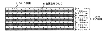
前記積層(3)を構成する、前記金属含有DLC皮膜(5)、又はDLC皮膜(4)の一層の厚さが、0.01〜0.5μmであり、積層(3)全体の厚さが1μm以上にすることが好ましい。
残留応力の低減、製造し易さを考慮すると、前記積層(3)を構成する金属含有DLC皮膜(5)の厚さと、該積層(3)を構成するDLC皮膜(4)の厚さが略同等であることが好ましい。しかし、金属ターゲット源と炭化水素ターゲット源の構成数によって多少変動することもある。
The thickness of one layer of the metal-containing DLC film (5) or DLC film (4) constituting the laminate (3) is 0.01 to 0.5 μm, and the entire thickness of the laminate (3) is It is preferable to make it 1 μm or more.
Considering reduction of residual stress and ease of manufacture, the thickness of the metal-containing DLC film (5) constituting the laminate (3) and the thickness of the DLC film (4) constituting the laminate (3) are approximately It is preferable that they are equivalent. However, it may vary somewhat depending on the number of constituent metal target sources and hydrocarbon target sources.
本発明の製造方法によれば、アンバランスド・マグネトロン・スパッタリング法(UBMS法)により、基材(1)の表面に、中間層(2)、及びDLC皮膜(4)と金属を含有した金属含有DLC皮膜(5)とから成る積層(3)を成膜する際に、中間層(2)とDLC積層(3)のコーティング処理温度を100〜200℃の雰囲気に設定する、ことを特徴とするDLC積層皮膜部材の製造方法が提供される。
前記アンバランスド・マグネトロン・スパッタリング法(UBMS法)により、中間層(2)及び、DLC皮膜(4)と金属を含有したDLC皮膜(5)とを交互に重ねた積層(3)を形成することが必要である。
According to the production method of the present invention, the metal containing the intermediate layer (2), the DLC film (4) and the metal on the surface of the substrate (1) by the unbalanced magnetron sputtering method (UBMS method). When forming the laminate (3) composed of the containing DLC film (5), the coating treatment temperature of the intermediate layer (2) and the DLC laminate (3) is set to an atmosphere of 100 to 200 ° C. A method for manufacturing a DLC laminated coating member is provided.
By the unbalanced magnetron sputtering method (UBMS method), an intermediate layer (2) and a laminate (3) in which the DLC film (4) and the DLC film (5) containing metal are alternately stacked are formed. It is necessary.
前記基材表面(1)に、中間層(2)及び、DLC皮膜(4)と金属を含有したDLC皮膜(5)とを交互に重ねた積層(3)を形成する際に、プラズマCVD法を利用することができる。
前記プラズマCVD法により、基材(1)の表面に、中間層(2)及び、DLC皮膜(4)と金属を含有した金属含有DLC皮膜(5)とを成膜する際に、そのコーティング処理温度を100〜200℃の雰囲気に設定することが必要である。
When forming the laminate (3) in which the intermediate layer (2) and the DLC film (4) and the DLC film (5) containing metal are alternately stacked on the substrate surface (1), a plasma CVD method is used. Can be used.
When the intermediate layer (2), the DLC film (4), and the metal-containing DLC film (5) containing metal are formed on the surface of the base material (1) by the plasma CVD method, the coating process is performed. It is necessary to set the temperature to an atmosphere of 100 to 200 ° C.
前記基材表面(1)に、中間層(2)及び、DLC皮膜(4)と、金属を含有したDLC皮膜(5)とを交互に重ねた積層(3)を形成する際に、イオン化蒸着法を利用することができる。
前記イオン化蒸着法により、基材(1)の表面に、中間層(2)及び、DLC皮膜(4)と金属を含有した金属含有DLC皮膜(5)とを成膜する際に、
そのコーティング処理温度を100〜200℃の雰囲気に設定することが必要である。
When forming the laminate (3) in which the intermediate layer (2), the DLC film (4), and the DLC film (5) containing metal are alternately stacked on the substrate surface (1), ionization deposition is performed. The law can be used.
When the intermediate layer (2), the DLC film (4), and the metal-containing DLC film (5) containing a metal are formed on the surface of the substrate (1) by the ionized vapor deposition method,
It is necessary to set the coating processing temperature to an atmosphere of 100 to 200 ° C.
上述したように、本発明のDLC積層皮膜部材では、基材(1)に成膜形成した積層(3)が、DLC皮膜(4)と、金属を含有した金属含有DLC皮膜(5)とを交互に重ねた構造であるために、この積層(3)により、アルミニウム又はマグネシウム等の非鉄金属の基材(1)の疲労強度を高めることができる。また、この積層(3)により、各種部材としての摩擦係数を低下させ、摩耗量を低減させることができる。更に、この積層(3)により基材(1)又は中間層(2)への密着性を向上させることができる。 As described above, in the DLC laminated film member of the present invention, the laminated film (3) formed on the substrate (1) comprises the DLC film (4) and the metal-containing DLC film (5) containing metal. Because of the alternately stacked structure, the laminate (3) can increase the fatigue strength of the nonferrous metal substrate (1) such as aluminum or magnesium. Moreover, this lamination (3) can reduce the friction coefficient as various members, and can reduce the amount of wear. Furthermore, the adhesion to the substrate (1) or the intermediate layer (2) can be improved by the lamination (3).
本発明品は、後述する表1に示すように、コーティング皮膜の厚さを厚くしても、コーティング皮膜密着力が低下することなく、むしろ増加している。一般的には、DLC皮膜は残留応力が大きく、超硬質で延性が殆どないため、コーティング厚さを厚くすると、皮膜の密着力は低下し、皮膜が剥がれ易くなる。このため、DLC皮膜を厚くしたくても厚くできず、実用上の皮膜厚さはせいぜい3μmが限界であった。しかるに本発明によるDLC皮膜は厚膜化によっても密着力が低下することなく、むしろ密着力が増加するので、厚いコーティング皮膜が可能となる。 As shown in Table 1 to be described later, the product of the present invention is rather increased without decreasing the coating film adhesion even when the coating film thickness is increased. In general, since the DLC film has a large residual stress, is super-hard, and has almost no ductility, when the coating thickness is increased, the adhesion of the film is reduced and the film is easily peeled off. For this reason, even if it is desired to increase the thickness of the DLC film, it cannot be increased, and the practical film thickness is limited to 3 μm at most. However, the DLC film according to the present invention does not decrease the adhesion force even when the film thickness is increased, but rather increases the adhesion force, so that a thick coating film is possible.
また、本発明の製造方法では、比較的低温度においてDLC皮膜(2、3、4)を形成することができるので、その基材強度の低下を抑制することができ、高い疲労強度を有し、皮膜密着性、摩擦摩耗特性の良いDLC積層皮膜部材を製造することができる。 Further, in the production method of the present invention, since the DLC film (2, 3, 4) can be formed at a relatively low temperature, it is possible to suppress a decrease in the strength of the base material and to have a high fatigue strength. In addition, a DLC laminated film member having good film adhesion and friction and wear characteristics can be produced.
本発明のDLC積層皮膜部材は、基材の表面に中間層と、中間層の表面に積層を成膜形成したDLC積層皮膜部材であり、積層は、ダイヤモンドライクカーボン皮膜と、金属を含有した金属含有DLC皮膜とを交互に重ねた構造である。 The DLC laminated film member of the present invention is a DLC laminated film member in which an intermediate layer is formed on the surface of the base material and a laminated film is formed on the surface of the intermediate layer. The laminated film is a diamond-like carbon film and a metal containing metal. This is a structure in which the contained DLC films are alternately stacked.
以下、本発明の好ましい実施の形態を、図面を参照して説明する。
図1は本発明の実施例1のDLC積層皮膜部材の断面図である。図2は積層部分の拡大断面図である。
本発明のDLC積層皮膜部材は、アルミニウム、マグネシウム又はチタン等の各合金から成る基材1の表面に中間層2と、この中間層2の表面に積層3を成膜形成した部材である。積層3は、DLC皮膜4と、金属を含有した金属含有DLC皮膜5とを交互に重ねた構造である。DLC皮膜4は、高硬度でダイヤモンドと似た物性を有するアモルファスなカーボン皮膜であり、水素を含有するものである。ここで、本発明が、水素を含有するDLCと規定した理由は、本発明のDLC積層が低コストで、極めて平滑な表面が得られるためである。水素を含有しないDLCは摩擦係数は小さなものが得られるが、固体炭素源を利用することによって、ドロップレットといわれる微小表面析出物が生成し、平滑な表面が得られない。これは摩擦に特に有害な物質であり、これを取除く工程が必要不可欠であるためである。これを取除かない場合、摩擦係数は増加し、摩耗も大きくなり、潤滑皮膜としての機能を全く果さなくなる。本発明の金属含有DLC皮膜5は、タングステン(W)、クロム(Cr)又はチタン(Ti)等の5〜15重量%の金属を含有する。
Hereinafter, preferred embodiments of the present invention will be described with reference to the drawings.
1 is a cross-sectional view of a DLC laminated film member of Example 1 of the present invention. FIG. 2 is an enlarged cross-sectional view of the laminated portion.
The DLC laminated film member of the present invention is a member in which an
中間層2は、金属を含有した金属含有ダイヤモンドライクカーボン皮膜5から成り、この金属含有DLC皮膜5は、基材1側に金属の含有率を高く、積層3側に金属の含有率を低くした傾斜構造である。この金属含有DLC皮膜5から成る中間層2は、0.05〜3.00μmの厚さを有する。この中間層2の厚さは基材の種類、部材の用途などに応じて決定される。
The
積層3を構成する、金属含有DLC皮膜5、又はDLC皮膜4の一層の厚さは、0.01〜0.5μmである。この積層3の厚さは、基材の種類、部材の用途などに応じて決定される。例えば、この積層3を構成する、金属含有DLC皮膜5の厚さは、DLC積層皮膜3)の厚さの1/4以下であることが好ましい。
The thickness of one layer of the metal-containing
積層3のDLC皮膜4と金属含有DLC皮膜5との積層数は、図示例の10層に限定されず、基材の種類、積層皮膜部材の用途、仕様などに応じて決定される。ナノ積層構造を採用することによって、積層皮膜内に発生する残留応力が低下し、従来のDLCにない高性能な厚膜の皮膜がコーティング可能である。本発明は厚さ3μm以上、好ましくは5μm以上であり、従来の方法では得られないような高性能な10μmもの厚膜のコーティングも可能である。
また、中間層の構造を変えることによって、様々な基材にも対応可能である。表層DLC皮膜の構造を積層化することによって、摩擦係数の低減を図ることも可能であり、疲労強度の向上も図ることができる。
The number of laminations of the
In addition, various substrates can be handled by changing the structure of the intermediate layer. By laminating the structure of the surface DLC film, the friction coefficient can be reduced and the fatigue strength can be improved.
図3は基材と金属を含まないDLCとの断面図である。
更に、図3に示すように、基材1に金属含有DLC皮膜5を直接成膜形成することも可能である。即ち、中間層2を省略することも可能である。
FIG. 3 is a cross-sectional view of a base material and a DLC not containing metal.
Furthermore, as shown in FIG. 3, the metal-containing
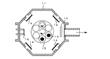
図4は実施例2のDLC積層皮膜部材の製造方法を説明する装置概略図である。
実施例2のDLC積層皮膜部材は、図4に示すような製造装置で成膜する。この真空チャンバ11に角型UBMスパッタ蒸発源4式が搭載され、中央に配置された自公転式ワークテーブル12上の基材1、即ちワーク13に外周からコーティングを行う。スパッタ源14には皮膜材料となる平板状ターゲット(127mm×508mm)が取り付けられ、装置としてはΦ450×H400mmの推奨処理空間を有する。スパッタ源14にはグロー放電を発生させるための電力を供給するスパッタ電源が接続され、ワークテーブル12には負のバイアス電圧を印加するバイアス電源が接続されている。
FIG. 4 is an apparatus schematic diagram for explaining a method for producing a DLC laminated film member of Example 2.
The DLC laminated film member of Example 2 is formed by a manufacturing apparatus as shown in FIG. The vacuum chamber 11 is equipped with a square UBM sputtering
図4に示す製造装置を用いたUBMスパッタ法による皮膜形成は以下のようにして製造する。
先ず、表面を十分に洗浄したワーク13を真空チャンバ11内にセットし、通常2×10⁻³Pa程度以下の高真空まで排気する。その後、ワーク13や真空チャンバ11内表面からの脱ガスを目的として、ワーク13をヒータ15で予備加熱する。加熱時間は形成する皮膜やワーク材質(耐熱虚度)、ワーク重量(熱容量)等に応じて適宜調整するが、ワーク温度が通常150〜200℃になるまで行う。
Film formation by the UBM sputtering method using the manufacturing apparatus shown in FIG. 4 is manufactured as follows.
First, the work 13 whose surface has been sufficiently cleaned is set in the vacuum chamber 11 and evacuated to a high vacuum of about 2 × 10 −3 Pa or less. Thereafter, the work 13 is preheated by the
次に、ワーク13に−300、−600V程度の高い負のバイアス電圧を印加するとともに、圧力1〜2Pa程度のArガス雰囲気中で、熱フィラメント型プラズマ源16を動作させ、生成したArイオンをワーク13に衝突させるボンバード工程を行う。この工程は高エネルギーイオンによりワーク表面をエッチングしてクリーニングするとともに、ワーク温度を上昇させることで、この後に形成される皮膜の密着をより強固にする役割を持つ。この工程は通常10〜30分程度行う。
Next, a high negative bias voltage of about −300 and −600 V is applied to the work 13, and the hot
ボンバード工程が終了すると、皮膜をコーティングする工程に入る。後に説明するDLC膜形成の場合は、ターゲットとして炭化水素ガス及び中間層用の金属ターゲットがスパッタ源14に取り付けられる。Arガス圧力をスバッタに適した圧力に変更し、また必要に応じてその他のプロセスガスを導入した後、ワーク13にバイアス電圧を印如しながら、スパッタ源に電力を供給して、グロー放電を発生させるとコーティングが開始する。コーティング時の標準的な条件は、Ar圧力0.1〜1Pa程度、バイアス電圧−20〜−200V、スパッタ電力1〜10kWである。皮膜の膜厚のコントロールはスパッタ電力とコーティング時間の調節で行われる。
所定の膜厚に達したら、スパッタ源への電力供給を止めて・コーティングを終了し、ワーク13の冷却を待って真空チャンバ11から取り出す。
When the bombardment process is completed, the process of coating the film is started. In the case of forming a DLC film, which will be described later, a hydrocarbon gas and a metal target for an intermediate layer are attached to the
When the predetermined film thickness is reached, the power supply to the sputtering source is stopped. The coating is terminated, and the workpiece 13 is removed from the vacuum chamber 11 after cooling.
[コーティング例1]
図5はタングステンを含有させる際のスパッタリング電力と時間との関係を示すグラフである。図6はタングステン含有のDLC傾斜構造を有する積層皮膜部材の断面図である。
上述した図4に示すようなUBMスパッタ装置を用いたDLC積層皮膜部材の製造方法によるコーティング例1を示す。
基材1は直径15mm、高さ10mmのSCM415の浸炭処理材を用い、これを脱脂してコーティングを行った。この基材1をUBMS装置(アンバランスド・マグネトロン・スパッタリング装置)の真空チャンバ11内に取付け、5×10―3Pa程度以下の真空にまで排気する。ヒータ15にて基材1をベーキングし、Arプラズマにて基材1表面をエッチングする。その後、2.6×10―3Paで、UBMS法により表1に示すような各種層構成のDLC多層膜を形成した。
[Coating Example 1]
FIG. 5 is a graph showing the relationship between sputtering power and time when tungsten is contained. FIG. 6 is a cross-sectional view of a laminated film member having a tungsten-containing DLC gradient structure.
The coating example 1 by the manufacturing method of the DLC laminated film member using the UBM sputtering apparatus as shown in FIG. 4 mentioned above is shown.
The

ここで中間層2はWを10%含むDLCであり、表層DLC積層は層厚さ0.1μmのDLC層とW含有DLC層を交互に積層し、表面DLC積層皮膜をそれぞれ1μmと3μm厚さに仕上げたものである。最表層は硬質のDLC層である。表1におけるNo.2のコーティング後の断面の状況は図6に示す。
Here, the
図4の真空チャンバ11において、中央のワークテーブル12にワーク13を設置する。本発明のコーティングを行うために、1箇所の蒸発源にタングステン(W)を設置し、残りの蒸発源にはベンゼンなどの炭化水素ガスを用いてコーティングを行う。
タングステンを含有させる方法は図5に示すように、基材1に接する中間層2は基材1側のW含有量を約100%と高くし、表面の積層3側は約10%に低下させた傾斜材とする。
In the vacuum chamber 11 of FIG. 4, a work 13 is set on a central work table 12. In order to perform the coating of the present invention, tungsten (W) is installed in one evaporation source, and the remaining evaporation source is coated using a hydrocarbon gas such as benzene.
As shown in FIG. 5, the
積層部はW蒸発源のスパッタ電力の付加の有無で行い、電力付加をしているときにWが含有され、付加しないときにはWを含有しない。W付加電力は0.09kWである。DLCは所定の電力でコーティングし、処理温度は120℃である。 The stacking part is performed with or without the addition of sputtering power from the W evaporation source, and contains W when power is applied, and does not contain W when power is not applied. The W additional power is 0.09 kW. The DLC is coated with a predetermined power, and the processing temperature is 120 ° C.
[コーティング例2]
UBMスパッタ装置を用いたコーティング例2を示す。基材1は直径15mm、高さ10mmのアルミニウム合金A6061(T6処理品)を用い、コーティング例1と同様にして、表2に示すようなDLC多層積層膜を形成した。
[Coating Example 2]
The coating example 2 using a UBM sputtering device is shown. As the
ここで中間層はWを10%含むDLCであり、表層DLC積層は層厚さ0.1μmのDLC層とW含有DLC層を交互に積層し、表面DLC積層皮膜をそれぞれ1μmと3μm厚さに仕上げたものである。最表層は硬質のDLC層である。 Here, the intermediate layer is a DLC containing 10% of W, and the surface DLC stack is formed by alternately stacking a DLC layer having a thickness of 0.1 μm and a W-containing DLC layer, and forming a surface DLC layered film to a thickness of 1 μm and 3 μm, respectively. Finished. The outermost layer is a hard DLC layer.
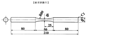
図7は疲労強度試験を測定する際に用いた疲労試験片の一例を示す正面図と側面図である。図8はアルミ材の疲労強度へのDLCの効果を示すグラフである。グラフの縦軸は強度振幅(単位MPa)、横軸は繰り返し回数を示す。
ここで、「Virgin」:コーティングしてない部材
「L−DLC」:中間層2μm+積層1μm
「Thick−DLC」:中間層2μm+積層1μm をそれぞれあらわしている。
FIG. 7 is a front view and a side view showing an example of a fatigue test piece used in measuring the fatigue strength test. FIG. 8 is a graph showing the effect of DLC on the fatigue strength of an aluminum material. The vertical axis of the graph represents intensity amplitude (unit MPa), and the horizontal axis represents the number of repetitions.
Here, “Virgin”: Uncoated member “L-DLC”:
“Thick-DLC”:
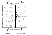
図9は疲労破壊のメカニズムを示す説明図であり、(a)はコーティングしていない部材、(b)はDLCをコーティングした部材である。
Al材の疲労破壊は材料表面のボイド、即ち粒子(Mg−Si−O Particles)が起点となって、疲労破壊(Fatiguue crack)が部材表面から発生している(図9(a)の状態)。しかし、DLCをコーティングすることによって、このボイドが塞がれ、疲労破壊は部材内部から発生する(図9(b)の状態)。このため、疲労強度を向上させることができる。マグネシウムとチタンにおいても同様な疲労破壊のメカニズムがあり、本発明のようなDLCコーティングが疲労強度の向上に有効である。
FIG. 9 is an explanatory view showing the mechanism of fatigue fracture, where (a) is a member not coated, and (b) is a member coated with DLC.
Fatigue fracture of the Al material starts from voids on the material surface, that is, particles (Mg—Si—O Particles), and fatigue fracture occurs from the surface of the member (state of FIG. 9A). . However, by coating DLC, this void is closed and fatigue failure occurs from inside the member (the state of FIG. 9B). For this reason, fatigue strength can be improved. Magnesium and titanium also have a similar fatigue fracture mechanism, and a DLC coating like the present invention is effective in improving fatigue strength.
図10はDLC被膜なし部材、DLC単層皮膜部材と本発明のDLC積層皮膜部材との摩擦係数と滑動距離との関係を示すグラフである。
このグラフでは、その上段から順番にDLC被膜なし部材、DLC単層皮膜部材、3μmのDLC積層皮膜部材、5μmのDLC積層皮膜部材を示している。本発明のDLC積層皮膜部材は、このグラフに示すように、例えば3μmのDLC積層皮膜部材は、3μmのDLC単層皮膜部材より摩擦係数が小さい。5μm程度のDLC積層皮膜部材は更に摩擦係数が小くなる。
FIG. 10 is a graph showing the relationship between the coefficient of friction and the sliding distance between the DLC film-less member, the DLC single-layer film member, and the DLC laminated film member of the present invention.
In this graph, a DLC film-less member, a DLC single-layer film member, a 3 μm DLC laminated film member, and a 5 μm DLC laminated film member are shown in order from the top. As shown in this graph, the DLC laminated film member of the present invention has a smaller coefficient of friction than, for example, a 3 μm DLC laminated film member than a 3 μm DLC single layer film member. A DLC laminated film member having a thickness of about 5 μm has a smaller friction coefficient.
本発明は、比較的低温度により中間層2及びDLCの積層3を形成することで、基材強度の低下を抑制することができ、更に基材1へのDLC皮膜の成膜法を工夫することにより、疲労強度が高くなることのみならず、皮膜密着性、摩擦摩耗特性を向上させることができれば、上述した発明の実施の形態に限定されず、本発明の要旨を逸脱しない範囲で種々変更できることは勿論である。
In the present invention, by forming the
本発明のダイヤモンドライクカーボン積層皮膜部材及びその製造方法は、優れた摩擦・磨耗特性のみならず、疲労強度の向上を果たすことから、自動車部品などに利用することができる。 The diamond-like carbon laminated film member and the method for producing the same according to the present invention can be used for automobile parts and the like because they improve not only excellent friction and wear characteristics but also fatigue strength.
1 基材
2 中間層
3 積層
4 DLC皮膜
5 金属含有DLC皮膜
DESCRIPTION OF
Claims (13)
前記積層(3)は、DLC皮膜(4)と、金属を含有した金属含有DLC皮膜(5)とを交互に重ねた構造である、ことを特徴とするDLC積層皮膜部材。 Diamond-like carbon (DLC) in which an intermediate layer (2) is formed on the surface of a base material (1) made of an alloy of aluminum, magnesium, titanium, or the like, and a laminate (3) is formed on the surface of the intermediate layer (2) A laminated coating member,
The laminate (3) has a structure in which a DLC coating (4) and a metal-containing DLC coating (5) containing a metal are alternately stacked.
中間層(2)とDLC積層(3)のコーティング処理温度を100〜200℃の雰囲気に設定する、ことを特徴とするDLC積層皮膜部材の製造方法。 By the unbalanced magnetron sputtering method (UBMS method), the surface of the base material (1) is composed of an intermediate layer (2), a DLC film (4), and a metal-containing DLC film (5) containing a metal. When forming the laminate (3),
A method for producing a DLC laminated coating member, characterized in that the coating temperature of the intermediate layer (2) and the DLC laminate (3) is set to an atmosphere of 100 to 200 ° C.
そのコーティング処理温度を100〜200℃の雰囲気に設定する、ことを特徴とする請求項10のDLC積層皮膜部材の製造方法。 When the intermediate layer (2), the DLC film (4), and the metal-containing DLC film (5) containing metal are formed on the surface of the substrate (1) by the plasma CVD method,
The method for producing a DLC laminated coating member according to claim 10, wherein the coating treatment temperature is set to an atmosphere of 100 to 200 ° C.
そのコーティング処理温度を100〜200℃の雰囲気に設定する、ことを特徴とする請求項12のDLC積層皮膜部材の製造方法。 When the intermediate layer (2), the DLC film (4), and the metal-containing DLC film (5) containing a metal are formed on the surface of the substrate (1) by the ionized vapor deposition method,
The method for producing a DLC laminated coating member according to claim 12, wherein the coating treatment temperature is set to an atmosphere of 100 to 200 ° C.
Priority Applications (1)
| Application Number | Priority Date | Filing Date | Title |
|---|---|---|---|
| JP2006199802A JP2008024996A (en) | 2006-07-21 | 2006-07-21 | Diamond-like carbon laminated coating film member and method of manufacturing the same |
Applications Claiming Priority (1)
| Application Number | Priority Date | Filing Date | Title |
|---|---|---|---|
| JP2006199802A JP2008024996A (en) | 2006-07-21 | 2006-07-21 | Diamond-like carbon laminated coating film member and method of manufacturing the same |
Publications (1)
| Publication Number | Publication Date |
|---|---|
| JP2008024996A true JP2008024996A (en) | 2008-02-07 |
Family
ID=39115946
Family Applications (1)
| Application Number | Title | Priority Date | Filing Date |
|---|---|---|---|
| JP2006199802A Pending JP2008024996A (en) | 2006-07-21 | 2006-07-21 | Diamond-like carbon laminated coating film member and method of manufacturing the same |
Country Status (1)
| Country | Link |
|---|---|
| JP (1) | JP2008024996A (en) |
Cited By (10)
| Publication number | Priority date | Publication date | Assignee | Title |
|---|---|---|---|---|
| JP2009544844A (en) * | 2006-07-26 | 2009-12-17 | ロバート ボッシュ ゲーエムベーハー | Method of applying a coating material and coating for a metal surface |
| DE102010048947A1 (en) | 2009-10-22 | 2011-04-28 | Yoshitaka Mitsuda | Diamond-like carbon film material and method for its production |
| KR20120042769A (en) * | 2009-08-13 | 2012-05-03 | 페데랄-모굴 부르샤이트 게엠베하 | Sliding element, in particular a piston ring, having a coating |
| CN102825305A (en) * | 2012-09-18 | 2012-12-19 | 上海壳瑞微材料科技有限公司 | Printing circuit board (PCB) micro-drill for nano compound coating of hard-alloy substrate and preparation method of micro-drill |
| KR101516128B1 (en) * | 2014-10-13 | 2015-05-04 | 이원규 | Temperature sensor device for measuring the heat temperature of casting and die casting molten metal (melt) and its recycling protective pipe manufacturing method |
| JP2016037637A (en) * | 2014-08-07 | 2016-03-22 | 国立大学法人豊橋技術科学大学 | Dlc film formation method and dlc film formation device |
| JP2017160899A (en) * | 2016-03-08 | 2017-09-14 | 儀徴亜新科双環活塞環有限公司 | Diamond-like carbon-coating layer for piston ring surface, piston ring and manufacturing process |
| US20180301716A1 (en) * | 2015-02-23 | 2018-10-18 | Hyundai Motor Company | Coating method of separator for fuel cell and separator for fuel cell |
| KR20190098399A (en) * | 2018-02-14 | 2019-08-22 | 연세대학교 산학협력단 | Diamond like carbon films implant metal and method for manufacturing the same |
| CN112707367A (en) * | 2020-12-30 | 2021-04-27 | 中国人民解放军陆军工程大学 | Diamond-like protective film and preparation method thereof |
-
2006
- 2006-07-21 JP JP2006199802A patent/JP2008024996A/en active Pending
Cited By (16)
| Publication number | Priority date | Publication date | Assignee | Title |
|---|---|---|---|---|
| JP2009544844A (en) * | 2006-07-26 | 2009-12-17 | ロバート ボッシュ ゲーエムベーハー | Method of applying a coating material and coating for a metal surface |
| KR101719696B1 (en) | 2009-08-13 | 2017-03-24 | 페데랄-모굴 부르샤이트 게엠베하 | Sliding element, in particular a piston ring, having a coating |
| KR20120042769A (en) * | 2009-08-13 | 2012-05-03 | 페데랄-모굴 부르샤이트 게엠베하 | Sliding element, in particular a piston ring, having a coating |
| DE102010048947A1 (en) | 2009-10-22 | 2011-04-28 | Yoshitaka Mitsuda | Diamond-like carbon film material and method for its production |
| TWI504766B (en) * | 2009-10-22 | 2015-10-21 | Yoshitaka Mitsuda | Diamond-like carbon film-formed material and method for producing the same |
| US9598762B2 (en) | 2009-10-22 | 2017-03-21 | Yoshitaka MITSUDA | Diamond-like carbon film-formed material and method for producing the same |
| CN102825305A (en) * | 2012-09-18 | 2012-12-19 | 上海壳瑞微材料科技有限公司 | Printing circuit board (PCB) micro-drill for nano compound coating of hard-alloy substrate and preparation method of micro-drill |
| JP2016037637A (en) * | 2014-08-07 | 2016-03-22 | 国立大学法人豊橋技術科学大学 | Dlc film formation method and dlc film formation device |
| KR101516128B1 (en) * | 2014-10-13 | 2015-05-04 | 이원규 | Temperature sensor device for measuring the heat temperature of casting and die casting molten metal (melt) and its recycling protective pipe manufacturing method |
| US20180301716A1 (en) * | 2015-02-23 | 2018-10-18 | Hyundai Motor Company | Coating method of separator for fuel cell and separator for fuel cell |
| US11233248B2 (en) | 2015-02-23 | 2022-01-25 | Hyundai Motor Company | Coating method of separator for fuel cell and separator for fuel cell |
| JP2017160899A (en) * | 2016-03-08 | 2017-09-14 | 儀徴亜新科双環活塞環有限公司 | Diamond-like carbon-coating layer for piston ring surface, piston ring and manufacturing process |
| KR20190098399A (en) * | 2018-02-14 | 2019-08-22 | 연세대학교 산학협력단 | Diamond like carbon films implant metal and method for manufacturing the same |
| KR102081264B1 (en) * | 2018-02-14 | 2020-02-25 | 연세대학교 산학협력단 | Metal containing DLC films and method for manufacturing the same |
| CN112707367A (en) * | 2020-12-30 | 2021-04-27 | 中国人民解放军陆军工程大学 | Diamond-like protective film and preparation method thereof |
| CN112707367B (en) * | 2020-12-30 | 2024-02-27 | 中国人民解放军陆军工程大学 | Diamond-like protective film and preparation method thereof |
Similar Documents
| Publication | Publication Date | Title |
|---|---|---|
| JP2008024996A (en) | Diamond-like carbon laminated coating film member and method of manufacturing the same | |
| JP5393108B2 (en) | Manufacturing method of hard multilayer film molded body | |
| US10006547B2 (en) | Piston ring and its production method | |
| JP2018501408A (en) | Cutting tool with multilayer PVD coating | |
| EP2103707B1 (en) | An aerospace bearing component | |
| JP6084032B2 (en) | Steel-coated article and manufacturing method thereof | |
| JP3590579B2 (en) | Diamond coated member and method of manufacturing the same | |
| JP2007070667A (en) | Formed article with hard multilayer film of diamond-like carbon, and production method therefor | |
| CN106893987B (en) | Preparation method of physical vapor deposition Ta-C coating and Ta-C coating | |
| JP2011089172A (en) | Diamond-like carbon film formed member and method for producing the same | |
| JP2008001951A (en) | Diamond-like carbon film and method for forming the same | |
| JP2020537048A (en) | AlCrSiN coating that changes the gradient of Si content and crystal size of ion source reinforcement | |
| CN110408889B (en) | Wear-resistant antifriction carbon-doped TiAlN nano multilayer hard film and preparation method thereof | |
| JP2014098184A (en) | Slide member having multilayer dlc film | |
| JP2006307318A (en) | Method for producing alpha-alumina layer-formed member and surface treatment | |
| JP4848545B2 (en) | Hard coating member and method for producing the same | |
| CN116670319A (en) | Hard carbon coating with improved adhesion strength by HIPIMS and method thereof | |
| JP5226826B2 (en) | Method for producing diamond-like carbon hard multilayer film molded body | |
| WO2016111288A1 (en) | Diamond-like carbon layered laminate and method for manufacturing same | |
| JP2015200009A (en) | Zirconium composite material coating layer, and forming method therefor | |
| JP4984206B2 (en) | Diamond-like carbon film-coated member and method for producing the same | |
| JP2004316850A (en) | Sliding member and its manufacturing method | |
| JP5360603B2 (en) | Method for producing amorphous carbon-coated member | |
| JP5924908B2 (en) | Method for producing hard coating member | |
| JP2001192206A (en) | Method for manufacturing amorphous carbon-coated member |