JP2007514457A - System and method for creating straight and non-linear grooves using routers in silicon and other crystalline materials - Google Patents
System and method for creating straight and non-linear grooves using routers in silicon and other crystalline materials Download PDFInfo
- Publication number
- JP2007514457A JP2007514457A JP2006527066A JP2006527066A JP2007514457A JP 2007514457 A JP2007514457 A JP 2007514457A JP 2006527066 A JP2006527066 A JP 2006527066A JP 2006527066 A JP2006527066 A JP 2006527066A JP 2007514457 A JP2007514457 A JP 2007514457A
- Authority
- JP
- Japan
- Prior art keywords
- crystalline material
- wafer
- blade
- machining
- silicon
- Prior art date
- Legal status (The legal status is an assumption and is not a legal conclusion. Google has not performed a legal analysis and makes no representation as to the accuracy of the status listed.)
- Pending
Links
Images


Classifications
-
- A—HUMAN NECESSITIES
- A61—MEDICAL OR VETERINARY SCIENCE; HYGIENE
- A61B—DIAGNOSIS; SURGERY; IDENTIFICATION
- A61B17/00—Surgical instruments, devices or methods, e.g. tourniquets
- A61B17/32—Surgical cutting instruments
-
- A—HUMAN NECESSITIES
- A61—MEDICAL OR VETERINARY SCIENCE; HYGIENE
- A61B—DIAGNOSIS; SURGERY; IDENTIFICATION
- A61B17/00—Surgical instruments, devices or methods, e.g. tourniquets
- A61B17/32—Surgical cutting instruments
- A61B17/3209—Incision instruments
- A61B17/3211—Surgical scalpels, knives; Accessories therefor
-
- A—HUMAN NECESSITIES
- A61—MEDICAL OR VETERINARY SCIENCE; HYGIENE
- A61B—DIAGNOSIS; SURGERY; IDENTIFICATION
- A61B17/00—Surgical instruments, devices or methods, e.g. tourniquets
- A61B2017/00526—Methods of manufacturing
-
- B—PERFORMING OPERATIONS; TRANSPORTING
- B26—HAND CUTTING TOOLS; CUTTING; SEVERING
- B26B—HAND-HELD CUTTING TOOLS NOT OTHERWISE PROVIDED FOR
- B26B21/00—Razors of the open or knife type; Safety razors or other shaving implements of the planing type; Hair-trimming devices involving a razor-blade; Equipment therefor
- B26B21/54—Razor-blades
- B26B21/58—Razor-blades characterised by the material
Abstract
外科用途またはその他の用途用のブレードを、好ましくはウェーハ(202)の形態の結晶質材料または多結晶材料から製造する方法は、ウェーハを取り付け、ウェーハに溝を機械加工することによって、結晶ウェーハまたは多結晶ウェーハを準備することを具える。斜面ブレードの表面を形成する溝を機械加工するための方法は、ダイヤモンドブレードソー,レーザシステム,超音波加工,熱間鍛造およびルータ(620)を具えている。ルータ(620)を用いる場合、溝の開始位置を規定する貫通穴(622)がウェーハ(202)に穿設される。溝が形成された後、エッチング液中にウェーハが置かれ、このエッチング液によりウェーハが均一に等方エッチングされて結晶性材料または多結晶材料の層が均一に除去され、各斜面が1つ以上のファセットを有する片面傾斜または両面傾斜のブレードが製作される。エッチング後に残るウェーハには、ほぼいかなる斜面角を機械加工することもできる。その結果得られるブレードの刃先半径は5〜500nmであり、それは刃先がダイヤモンドのブレードと同径であるが、その何分の1かのコストで製造される。
A method of manufacturing a blade for surgical or other applications, preferably from a crystalline or polycrystalline material in the form of a wafer (202), comprises attaching a wafer and machining a groove in the wafer, Providing a polycrystalline wafer; The method for machining the grooves forming the surface of the bevel blade comprises a diamond blade saw, a laser system, ultrasonic machining, hot forging and a router (620). When the router (620) is used, a through hole (622) that defines the start position of the groove is formed in the wafer (202). After the groove is formed, the wafer is placed in an etching solution, and the wafer is uniformly and isotropically etched by this etching solution to uniformly remove the crystalline material or polycrystalline material layer, and one or more slopes are formed. A single-sided or double-sided blade with a facet of Almost any bevel angle can be machined on the wafer remaining after etching. The resulting blade has a cutting edge radius of 5 to 500 nm, which is the same diameter as a diamond blade, but is manufactured at a fraction of the cost.
Description
本出願は、米国特許法第119条(e)による優先権を2003年9月17日に出願された米国仮特許出願第60/503458号に関して主張し、この仮出願の内容全体が参照することによってこの明細書に明確に組み込まれる。 This application claims priority under US Patent Section 119 (e) with respect to US Provisional Patent Application No. 60 / 503,458, filed on September 17, 2003, the entire contents of which are hereby incorporated by reference. Specifically incorporated herein by reference.
本発明は、外科用器具の製造のためのシステムおよび方法に関する。より詳細には、本発明は、様々な種類の非医療用および医療用ブレードで用いるため、直線状または非直線状の溝を、シリコンまたはその他の結晶質材料にルータを用いて製作するためのシステムおよび方法に関する。 The present invention relates to systems and methods for the manufacture of surgical instruments. More particularly, the present invention is for use in various types of non-medical and medical blades for making straight or non-linear grooves using a router in silicon or other crystalline material. The present invention relates to a system and method.
既存の手術刀は、様々な異なる方法により製造され、各方法は、それぞれ固有の利点および欠点を有する。最も一般的な製造方法は、ステンレス鋼を機械的に研削することである。ブレードは、鋭利な刃先を得るために(超音波スラリ,機械的研磨およびラッピングなど様々な異なる方法により)段階的に研磨されるか、または電気化学的にポリシングされる。こうした方法の利点は、それらが使い捨てのブレードを大量に製作するための確立された経済的プロセスであることである。こうしたプロセスの最大の欠点は、刃先の品質が変わりやすいことであり、より一貫性の高い鋭利度を得ることが依然課題となっている。これは主に、プロセス自体の固有の制約による。ブレードの刃先半径は30nmから1000nmの範囲の可能性がある。 Existing surgical knives are manufactured by a variety of different methods, each method having its own advantages and disadvantages. The most common manufacturing method is to mechanically grind stainless steel. The blade is polished stepwise (by various different methods such as ultrasonic slurry, mechanical polishing and lapping) or electrochemically polished to obtain a sharp cutting edge. The advantage of these methods is that they are an established economic process for making large quantities of disposable blades. The biggest drawback of these processes is that the quality of the cutting edge is variable, and it remains a challenge to obtain a more consistent sharpness. This is mainly due to inherent limitations of the process itself. The blade tip radius may be in the range of 30 nm to 1000 nm.
ブレード製造の比較的新しい方法では、研削の代わりにステンレス鋼のコイニングを用いる。ブレードはその後、鋭利な刃先を得るために電気化学的にポリシングされる。このプロセスは、研削方法よりも経済的であることがわかってきた。また、より一貫性の高い鋭利度を有するブレードを製作できることも明らかになってきた。この方法の欠点は、その鋭利度の一貫性が依然、ダイヤモンドブレードの製造プロセスで得られるよりも低いことである。軟部組織手術に対して金属ブレードを使用することは、その使い捨て可能なコストおよび改良された品質により、今日では一般的である。 A relatively new method of blade manufacture uses stainless steel coining instead of grinding. The blade is then electrochemically polished to obtain a sharp cutting edge. This process has been found to be more economical than the grinding method. It has also become clear that blades with more consistent sharpness can be produced. The disadvantage of this method is that its sharpness consistency is still lower than obtained in the diamond blade manufacturing process. The use of metal blades for soft tissue surgery is common today due to its disposable cost and improved quality.
ダイヤモンドブレードは、多くの外科市場、特に眼科手術市場における、鋭利度の最高基準である。ダイヤモンドブレードは、組織による最小限の抵抗を受け、軟部組織を滑らかに切断できることで知られている。ダイヤモンドブレードはまた、切断を繰り返しても一貫して鋭利であるため、その使用が望ましい。金属ブレードの究極的な鋭利度および鋭利度の変わりやすさは、ダイヤモンドブレードのそれに比べて劣るので、大多数の外科医がダイヤモンドブレードを使用する。ダイヤモンドブレードの製作に使用される製造プロセスでは、極めて鋭利で一貫した刃先半径を得るためにラッピングプロセスが用いられる。その結果得られるブレードの刃先半径は、5nmから30nmである。このプロセスの欠点は遅いことであり、その直接的な結果として、そのようなダイヤモンドブレードの製造コストが500ドルから5000ドルの範囲となることである。従ってこれらのブレードは、再利用の用途として販売される。このプロセスは現在、より低コストで同等の鋭利度を実現するため、ルビーまたはサファイアなどその他のより硬くない材料に対して用いられる。ただし、ダイヤモンドより高価ではないが、ルビーおよび/またはサファイアの外科用品質のブレードは依然、製造コストが50ドルから500ドルと比較的高く、その刃先が約200件しか持続しないという欠点を有する。従ってそれらのブレードは、再利用のために販売され、再利用の用途に限定される。 Diamond blades are the highest standard of sharpness in many surgical markets, especially the ophthalmic surgery market. Diamond blades are known to receive minimal resistance by the tissue and to cut soft tissue smoothly. Diamond blades are also desirable for their consistent sharpness with repeated cutting. Most surgeons use diamond blades because the ultimate sharpness and sharpness variability of metal blades is inferior to that of diamond blades. The manufacturing process used to make diamond blades uses a lapping process to obtain a very sharp and consistent cutting edge radius. The blade edge radius of the resulting blade is 5 nm to 30 nm. The disadvantage of this process is slow and the direct result is that the cost of manufacturing such a diamond blade is in the range of $ 500 to $ 5000. These blades are therefore sold for reuse. This process is currently used for other less rigid materials such as ruby or sapphire to achieve the same sharpness at lower cost. However, although less expensive than diamond, ruby and / or sapphire surgical quality blades still have the disadvantage of relatively high manufacturing costs of $ 50 to $ 500 and lasting only about 200 cutting edges. The blades are therefore sold for reuse and are limited to reuse applications.
シリコンを使用する手術刀の製造が、いくつか提案されてきた。しかし1つまたは別の形態で、これらのプロセスは、様々な構成および使い捨て可能なコストでブレードを製造する能力に限界がある。従来の多くの提案は、シリコンの異方性エッチングに基づく。異方性エッチング処理は、エッチングが高い方向性を有し、それぞれ異なる方向で異なるエッチング速度を有するものである。このプロセスでは、鋭利な切れ刃を製作することができる。ただしそれは、プロセスの性質により、実現されるブレードの形状および刃先斜面角によって限定される。水酸化カリウム(KOH),エチレンジアミンピロカテコール(EDP)およびトリメチル−2−ヒドロキシエチルアンモニウムヒドロキシド(TMAH)浴を用いるものなど、ウェットバルク異方性エッチング処理では、鋭利な刃先を得るため、特定の結晶面に沿ってエッチングが行われる。この面、通常、シリコン<100>の(111)面は、シリコンウェーハの表面から54.7°傾斜している。これは54.7°の刃先斜面角を生み出すが、この角度は鈍すぎるため、ほとんどの外科用途で臨床的に許容されないことが明らかになっている。この技術が両面傾斜ブレードの製作に適用される場合は刃先斜面角が109.4°になるため、その応用はより一層困難となる。このプロセスはさらに、それが製作できるブレードのプロファイルに限定される。エッチング面がウェーハで相互に90°に配される。従って、矩形プロファイルを有するブレードしか製作することができない。 Several manufactures of surgical knives using silicon have been proposed. However, in one or another form, these processes are limited in their ability to manufacture blades in a variety of configurations and disposable costs. Many conventional proposals are based on anisotropic etching of silicon. In the anisotropic etching process, etching has a high directionality and has different etching rates in different directions. This process can produce a sharp cutting edge. However, it is limited by the nature of the process and by the blade shape and the bevel angle. In wet bulk anisotropic etching processes, such as those using potassium hydroxide (KOH), ethylenediamine pyrocatechol (EDP) and trimethyl-2-hydroxyethylammonium hydroxide (TMAH) baths, a specific cutting edge is obtained to obtain a sharp edge. Etching is performed along the crystal plane. This plane, usually the (111) plane of silicon <100>, is inclined 54.7 ° from the surface of the silicon wafer. This produces a cutting edge angle of 54.7 °, but this angle is too blunt to prove clinically unacceptable for most surgical applications. When this technique is applied to the manufacture of double-sided inclined blades, the slope angle of the cutting edge becomes 109.4 °, and the application becomes even more difficult. This process is further limited to the profile of the blade it can produce. Etching surfaces are arranged at 90 ° to each other on the wafer. Therefore, only blades having a rectangular profile can be produced.
従って、上述した方法の短所に対処するブレードを製造することが必要とされている。本発明のシステムおよび方法では、ダイヤモンドブレードと同様の鋭利度を有し、使い捨て可能なコストの、ステンレス鋼の方法によるブレードを製作することができる。さらに、本発明のシステムおよび方法では、ブレードを厳密なプロセス制御を行いながら大量に製作することができる。さらに、本発明のシステムおよび方法では、直線状および非直線状両方のブレード斜面を有する外科用およびその他様々な種類のブレードを製作することができる。 Accordingly, there is a need to manufacture a blade that addresses the shortcomings of the methods described above. The system and method of the present invention can produce a stainless steel method blade that has the same sharpness as a diamond blade and is disposable. Furthermore, the system and method of the present invention allows the blades to be manufactured in large quantities with strict process control. Further, the system and method of the present invention can produce surgical and various other types of blades having both straight and non-linear blade bevels.
本発明により、上記欠点が克服されると共に多くの利点が実現される。本発明は、シリコンなどの結晶質または多結晶材料から手術刀を製造するシステムおよび方法に関し、結晶質材料または多結晶質材料に溝を機械加工することを、様々な方法により、いかなる所望の斜面角またはブレード形状でも実現する。次いで、機械加工された結晶ウェーハまたは多結晶ウェーハが等方性エッチング液中に浸漬され、これによって、ウェーハ材料の原子が1層ずつ除去され、半径が均一であって軟部組織手術用途に十分な質の切れ刃が形成される。本発明のシステムおよび方法は、このような高品質の手術刀を製造するための非常に安価な手段を提供する。 The present invention overcomes the above disadvantages and realizes many advantages. The present invention relates to a system and method for manufacturing a surgical knife from a crystalline or polycrystalline material such as silicon, and the machining of grooves in the crystalline or polycrystalline material can be performed in any desired manner by any method. Also realized in square or blade shape. The machined crystal wafer or polycrystalline wafer is then immersed in an isotropic etchant, which removes the layers of the wafer material layer by layer, has a uniform radius, and is sufficient for soft tissue surgery applications. A quality cutting edge is formed. The system and method of the present invention provides a very inexpensive means for producing such high quality surgical knives.
従って本発明の目的は、手術刀を製造する方法であって、シリコンまたはその他の結晶ウェーハまたは多結晶ウェーハを取り付けアセンブリに取り付けるステップと、直線状または非直線状の溝を形成するため、結晶ウェーハまたは多結晶ウェーハの第1の面に1つ以上の溝をルータで機械加工するステップと、1つ以上の手術刀を形成するため、結晶ウェーハまたは多結晶ウェーハの第1の面をエッチングするステップと、手術刀を別々にするステップと、手術刀を組み立てるステップとを具えた方法を提供することである。 Accordingly, it is an object of the present invention to provide a method for manufacturing a surgical knife comprising the steps of attaching a silicon or other crystal wafer or polycrystalline wafer to a mounting assembly, and forming a linear or non-linear groove to form a crystal wafer. Or machining one or more grooves in the first surface of the polycrystalline wafer with a router and etching the first surface of the crystalline wafer or polycrystalline wafer to form one or more surgical knives. And providing a method comprising the steps of separating the surgical knife and assembling the surgical knife.
本発明のさらなる目的は、手術刀を製造する方法であって、シリコンまたはその他の結晶ウェーハまたは多結晶ウェーハを取り付けアセンブリに取り付けるステップと、直線状または非直線状の溝を形成するため、結晶ウェーハまたは多結晶ウェーハの第1の面に1つ以上の溝をルータで機械加工するステップと、結晶ウェーハまたは多結晶ウェーハの第1の面を被膜で被覆するステップと、結晶ウェーハまたは多結晶ウェーハを取り付けアセンブリから取り外すステップと、結晶ウェーハまたは多結晶ウェーハの第1の面を取り付けアセンブリに再び取り付けるステップと、結晶ウェーハまたは多結晶ウェーハの第2の面を機械加工するステップと、1つ以上の手術刀を形成するため、結晶ウェーハまたは多結晶ウェーハの第2の面をエッチングするステップと、手術刀を別々にするステップと、手術刀を組み立てるステップとを具えた方法を提供することである。 A further object of the present invention is a method of manufacturing a surgical knife comprising attaching a silicon or other crystal wafer or polycrystalline wafer to a mounting assembly, and forming a linear or non-linear groove Or machining one or more grooves in the first surface of the polycrystalline wafer with a router; coating the first surface of the crystalline wafer or polycrystalline wafer with a coating; and Removing from the mounting assembly; reattaching the first surface of the crystal wafer or polycrystalline wafer to the mounting assembly; machining the second surface of the crystal wafer or polycrystalline wafer; and one or more surgeries To form the sword, the second surface of the crystal wafer or polycrystalline wafer is etched. A step of packaging, the step of separately a surgical blade, is to provide a method comprising the steps of assembling a surgical blade.
本発明のさらなる目的は、手術刀を製造する方法であって、シリコンまたはその他の結晶ウェーハまたは多結晶ウェーハを取り付けアセンブリに取り付けるステップと、直線状または非直線状の溝を形成するため、結晶ウェーハまたは多結晶ウェーハの第1の面に1つ以上の溝をルータで機械加工するステップと、結晶ウェーハまたは多結晶ウェーハを取り付けアセンブリから取り外すステップと、結晶ウェーハまたは多結晶ウェーハの第1の面を取り付けアセンブリに再び取り付けるステップと、直線状または非直線状の溝を形成するため、結晶ウェーハまたは多結晶ウェーハの第2の面をルータで機械加工するステップと、1つ以上の手術刀を形成するため、結晶ウェーハまたは多結晶ウェーハの第2の面をエッチングするステップと、硬化された表面を形成するため、結晶質材料または多結晶材料の層を転化するステップと、手術刀を別々にするステップと、手術刀を組み立てるステップとを具えた方法を提供することである。 A further object of the present invention is a method of manufacturing a surgical knife comprising attaching a silicon or other crystal wafer or polycrystalline wafer to a mounting assembly, and forming a linear or non-linear groove Or machining one or more grooves in the first surface of the polycrystalline wafer with a router, removing the crystalline wafer or polycrystalline wafer from the mounting assembly, and removing the first surface of the crystalline wafer or polycrystalline wafer. Re-attaching to the mounting assembly; machining a second surface of the crystalline or polycrystalline wafer with a router to form a linear or non-linear groove; and forming one or more surgical knives. Etching the second surface of the crystal wafer or polycrystalline wafer; To form the reduction surface, is to provide a step of converting the layer of crystalline material or a polycrystalline material, the method comprising separately a surgical blade, the method comprising the steps of assembling a surgical blade.
本発明の新規の特徴および利点は、以下の好ましい実施形態の詳細な説明を参照し、添付の図面と関連付けて読むことにより最もよく理解されよう。 The novel features and advantages of the present invention will be best understood by reference to the following detailed description of the preferred embodiments and read in conjunction with the accompanying drawings.
次に、好ましい実施形態の様々な特徴を、同様の部分が同一の参照符号で示される図面の図を参照しながら説明する。ここで考えられる本発明を実施する最良の形態の以下の説明は、限定的な意味として取られるべきではなく、単に本発明の全体的な原則を説明する目的で行うものに過ぎない。 Various features of the preferred embodiments will now be described with reference to the drawing figures, in which like parts are designated with like reference numerals. The following description of the best mode of carrying out the invention considered here is not to be taken in a limiting sense, but merely for the purpose of illustrating the general principles of the invention.
本発明のシステムおよび方法は、軟部組織の切開に使用される手術刀の製造を提供する。好ましい実施形態を手術刀として示すが、以下で詳細に述べる方法により多数の刃物を製作することもできる。従って、この説明全体を通して「手術刀」に関して述べるが、その他多くの種類の刃物、例えば医療用剃刀,ランセット,皮下注射針,試料採取カニューレおよびその他の医療用鋭利器具を製作できることが、本発明の分野の技術者には明らかであろう。さらに、本発明のシステムおよび方法により製造されたブレードは、例えば髭剃りおよび研究用途(すなわち組織採取)を含む他の非医療用途のためのブレードとして使用することができる。さらに、以下の説明全体を通して眼科用途について述べるが、多数のその他の医療用途は目,心臓,耳,脳,美容および再建手術を含むけれども、これらに限定されない。 The systems and methods of the present invention provide for the manufacture of surgical knives used for soft tissue incisions. Although the preferred embodiment is shown as a surgical knife, a number of blades can be made by the method described in detail below. Accordingly, while referring to “surgical knives” throughout this description, many other types of blades such as medical razors, lancets, hypodermic needles, sampling cannulas, and other medical sharps can be fabricated. It will be clear to the field engineer. Further, the blades produced by the systems and methods of the present invention can be used as blades for other non-medical applications including, for example, shaving and research applications (ie, tissue harvesting). Further, although ophthalmic applications are described throughout the following description, many other medical applications include, but are not limited to, eye, heart, ear, brain, cosmetic and reconstructive surgery.
当該分野の技術者にはよく知られているが、片面傾斜,両面傾斜およびファセットの用語を定義する。片面傾斜は、得られる鋭利な切れ刃がブレードの主面と同一平面にある、ブレード上の1つの斜面のことを指す。例えば、以下でさらに詳細に述べる図10Aを参照のこと。両面傾斜は、図10B,図20Aおよび図31Cに示すように、得られる鋭利な切れ刃が、得られるブレード全体を通る中心線と実質的に同一平面にあるブレード上の2つの斜面のことを指す。ファセットは、斜面にある平坦な縁部である。いかなるブレードにも、斜面1つごとに1つ,2つまたは複数のファセットが存在し得る。従って、いかなる1つのブレードにも、複数の鋭利な刃先(または、すなわち複数組の斜面)があり得、各斜面は単一または複数のファセットを有することができる。 As is well known to those skilled in the art, the terms single sided, double sided and facet are defined. Single-sided inclination refers to one bevel on the blade where the resulting sharp cutting edge is flush with the main surface of the blade. See, for example, FIG. 10A, described in further detail below. Double-sided slope refers to two slopes on a blade where the resulting sharp cutting edge is substantially flush with the centerline through the resulting blade, as shown in FIGS. 10B, 20A and 31C. Point to. A facet is a flat edge on a slope. Any blade can have one, two or more facets per bevel. Thus, any single blade can have multiple sharp cutting edges (or multiple sets of bevels), and each bevel can have a single or multiple facets.
ブレードを製造する好ましいベース材料は、好ましい結晶方位を有する結晶質シリコンである。ただし、シリコンのその他の方位ならびに等方性エッチングを施すことができるその他の材料も適当である。例えば、方位<110>および<111>を有するシリコンウェーハならびに様々な抵抗率および酸素含有率にてドープされたシリコンウェーハを使用することができる。また、窒化シリコンおよび砒化ガリウムなど、その他の材料で製作されたウェーハを使用することもできる。ウェーハの形態は、ベース材料として好ましい形態である。手術刀を製造するため、結晶質材料に加え、多結晶材料を使用することもできる。こうした多結晶材料の例として、多結晶シリコンが挙げられる。本明細書で使用するように、「結晶質」という用語は、結晶質材料および多結晶材料の両方を示すために用いられることが理解されよう。 A preferred base material for manufacturing the blade is crystalline silicon having a preferred crystal orientation. However, other orientations of silicon and other materials that can be isotropically etched are also suitable. For example, silicon wafers having orientations <110> and <111> and silicon wafers doped with various resistivity and oxygen content can be used. Wafers made of other materials such as silicon nitride and gallium arsenide can also be used. The form of the wafer is a preferred form as the base material. In addition to the crystalline material, a polycrystalline material can be used to manufacture the surgical knife. An example of such a polycrystalline material is polycrystalline silicon. As used herein, it will be understood that the term “crystalline” is used to indicate both crystalline and polycrystalline materials.
従って、この説明全体を通して「シリコンウェーハ」について述べるが、様々な方位で組み合わされたいかなる上記材料、ならびに利用可能となる他の適当な材料および方位を、本発明の様々な実施形態に従って使用できることも、本発明の分野の技術者には明らかであろう。 Accordingly, although a “silicon wafer” is described throughout this description, any of the above materials combined in various orientations, as well as other suitable materials and orientations that may be utilized, may be used in accordance with various embodiments of the present invention. It will be apparent to those skilled in the art of the present invention.
図1は、本発明の一実施形態による、両面傾斜手術刀をシリコンから製造するための方法を示す工程図である。図1,図2および図3の方法は、本発明によるシリコンの手術刀を製造するために使用することができるプロセスを全体的に示す。ただし、様々な基準のシリコン手術刀を製作するため、または様々な製造環境に合わせるため、図1,図2,図3に示す方法のステップの順番を変更することができる。 FIG. 1 is a process diagram illustrating a method for manufacturing a double-sided angled surgical knife from silicon according to an embodiment of the present invention. The method of FIGS. 1, 2 and 3 generally illustrates a process that can be used to manufacture a silicon surgical knife according to the present invention. However, the order of the steps of the method shown in FIGS. 1, 2 and 3 can be changed to produce different standards of silicon surgical swords or to suit different manufacturing environments.
例えば、以下に図示して説明するように、図1は本発明の第1の実施形態による両面傾斜ブレードを製造するための方法を示すが、この方法は切れ刃1つにつき複数(すなわち、3つ以上)のファセットを製作するために用いることができる。図31A〜図31Cはこのようなブレードを示し、以下により詳細に説明される。さらに、図示および説明する方法はまた、図32に示すように、斜面角変化両面傾斜ブレードを製造するために用いることができる。図32もまた、以下でさらに詳細に説明する。さらに、2つ(またはそれ以上)の斜面角を有する2つ(またはそれ以上)の切削面を持つシングルブレードのさらなる例として、本明細書で図示し説明する方法を用い、複数のブレードの刃先で様々な斜面角を有する図20Bおよび図20Dに示すブレードを製作することができる。そのように、図1,図2および図3の方法は、本発明による方法の全体的な実施形態を表すためのものであり、本発明の精神および範囲に従って製造されたシリコンの手術刀をもたらすことができる同じステップを具えた多くの異なる変更形態がある。 For example, as illustrated and described below, FIG. 1 illustrates a method for manufacturing a double-sided inclined blade according to a first embodiment of the present invention, but this method can include multiple methods per cutting edge (ie, 3 Can be used to make more than one facet. 31A-31C illustrate such a blade and will be described in more detail below. Further, the method shown and described can also be used to produce a bevel angle-changing double-sided bevel blade as shown in FIG. FIG. 32 is also described in further detail below. In addition, as a further example of a single blade having two (or more) cutting surfaces with two (or more) bevel angles, a plurality of blade tips can be used using the method illustrated and described herein. 20B and 20D having various slope angles can be manufactured. As such, the method of FIGS. 1, 2 and 3 is intended to represent an overall embodiment of the method according to the present invention, resulting in a silicon surgical knife manufactured in accordance with the spirit and scope of the present invention. There are many different variations that can be done with the same steps.
本発明の一実施形態による図1の方法は、好ましくはシリコンなどの結晶質材料を用いて両面傾斜の手術刀を製造するために使用され、ステップ1002から始まる。ステップ1002で、取り付けアセンブリ204にシリコンウェーハが取り付けられる。ウェーハフレーム/UVテープアセンブリ(取り付けアセンブリ)204に取り付けられたシリコンウェーハ202を図4に示す。取り付けアセンブリ204は、シリコンウェーハ材料を取り扱うための半導体分野における一般的な方法である。ウェーハ取り付けアセンブリ204に(結晶質)シリコンウェーハ202を取り付けることは、本発明の好ましい実施形態による手術刀の製造には必要ではないことを当該分野の技術者であれば理解することができる。
The method of FIG. 1 according to one embodiment of the present invention is used to manufacture a double-sided surgical knife, preferably using a crystalline material such as silicon, and begins at step 1002. At step 1002, a silicon wafer is attached to the
図5は、同一の取り付けアセンブリ204に取り付けられた同一のシリコンウェーハ202の側面図(左側または右側、これは線対称であるがそうでなくても良い)を示す。図5において、シリコンウェーハ202はテープ308に取り付けられ、次いでテープ308は取り付けアセンブリ204に取り付けられる。シリコンウェーハ202は、第1の面304および第2の面306を有する。
FIG. 5 shows a side view of the
再び図1を参照すると、決定ステップ1004が1002に続く。決定ステップ1004は、望まれる場合にステップ1006にて任意のプレカットをシリコンウェーハ202に対して行うか否かを決定する。このプレカットは、図6に示すようにレーザウォータジェット402によって行われる。取り付けアセンブリ204に取り付けられたシリコンウェーハ202にレーザビーム404を向けたレーザウォータジェット402を図6に示す。図6から分かるように、シリコンウェーハ202に対するレーザビーム404の衝突の結果として、様々なプレカットされた穴(すなわち基準貫通穴)406をシリコンウェーハ202に製作することができる。
Referring again to FIG. 1,
シリコンウェーハ202は、シリコンウェーハ202に向けたレーザビーム404によって溶融除去される。レーザビーム404がシリコンウェーハ202を溶融除去する能力は、レーザの波長λに関係する。シリコンウェーハを使用する好ましい実施形態で最良の結果をもたらす波長は1064nmであり、通常、YAGレーザによってもたらされるが、その他の種類のレーザもまた使用することができる。異なる結晶質材料または多結晶材料を使用する場合、別の波長および別の種類のレーザがより適当となる。
The
(このようにして複数の穴をあけることができる)結果的に得られた基準貫通穴406は、特に溝を機械加工するためにダイシングソーブレードを使用する場合、溝を機械加工するためのガイドとして使用することができる(以下でステップ1008にて詳細に述べる)。基準貫通穴406はまた、同じ目的用のいかなるレーザビーム(例えばエキシマレーザまたはレーザウォータジェット402)によってあけることができる。プレカットされた基準貫通穴は、一般にプラス「+」形状または円形にあけられる。ただし、基準貫通穴の形状の選択は、特定の製造工具および製造環境によって決まり、従って上述した2つの形状のみに限定する必要はない。
The resulting reference through hole 406 (which can be drilled in this way) is a guide for machining the groove, especially when using a dicing saw blade to machine the groove. (Described in detail below in step 1008). The reference through
基準貫通穴をプレカットするためにレーザビームを使用することに加え、その他の機械的な加工方法を使用することができる。それらは例えば、穿設工具,機械研削工具および超音波加工工具100を含むがこれらに限定されない。これらの装置の使用は、本発明の好ましい実施形態に関しては新規であるが、装置およびそれらの一般的な使用法は当該分野の技術者によく知られている。
In addition to using a laser beam to pre-cut the reference through hole, other mechanical processing methods can be used. They include, for example, but are not limited to drilling tools, mechanical grinding tools, and
シリコンウェーハ202のプレカットは、エッチング処理中にシリコンウェーハ202の完全性を維持してばらばらにならないようにするため、溝を機械加工する前に行うことができる。(図7A〜図7Cを参照して詳細に説明する)ダイシングブレード502が貫通溝を楕円形に移動してシリコンウェーハ202の周縁で溝の機械加工を開始するため、レーザビーム(例えばレーザウォータジェット402またはエキシマレーザ)を使用することができる。基準貫通穴を製作するために用いられる(上述した)機械的加工装置および方法はまた、貫通溝を作るために使用することができる。
A pre-cut of the
再び図1を参照すると、次のステップはステップ1008であり、このステップは、ステップ1006(基準貫通穴406がシリコンウェーハ202にあけられる場合)、またはシリコンウェーハ取り付けステップであるステップ1002および1004に続くことができる(「ステップ」1004は物理的製造ステップではなく、こうした決定ステップは製造プロセス全体およびその可変性を示すために含まれる)。ステップ1008では、シリコンウェーハ202の第1の面304に溝が機械加工される。製造条件およびシリコン手術刀の完成製品の所望の設計に応じて溝を機械加工するために利用できる複数の方法がある。
Referring again to FIG. 1, the next step is
機械加工のための方法では、ダイシングソーブレード,レーザシステム,超音波加工工具,熱間鍛造プロセスまたはルータを使用することができる。機械加工のためのその他の方法を使用することができる。それぞれを順に説明する。これらの方法の何れかによって機械加工される溝は、手術刀の角度(斜面角)を形成する。溝加工機械がシリコンウェーハ202に対して動作するに連れ、ダイシングソーブレードの形状,エキシマレーザによって形成されるパターンまたは超音波加工工具によって形成されるパターンにてシリコン材料が手術刀プリフォームの所望の形状に除去される。ダイシングソーブレードの場合、シリコン手術刀は直線状の刃先のみを有し、後の2つの方法では、ブレードは基本的にいかなる所望の形状とすることができる。熱間鍛造プロセスの場合、シリコンウェーハは加熱されて鍛造可能にされ、次いで2つの金型の間でプレスされる。2つの金型はそれぞれ、加熱された鍛造可能なシリコンウェーハに「成形」される所望の溝の3次元の型を有する。この説明のため、溝を「機械加工すること」は、特に述べた、ダイシングソーブレード,エキシマレーザ,超音波加工装置,ルータまたは熱間鍛造プロセスの何れかによる方法およびここで述べない同等の方法を含め、シリコンウェーハに溝を製作するすべての方法を包含する。次に、溝を機械加工するこれらの方法を詳細に説明する。
The method for machining can use a dicing saw blade, laser system, ultrasonic machining tool, hot forging process or router. Other methods for machining can be used. Each will be described in turn. The groove machined by any of these methods forms the angle (slope angle) of the surgical knife. As the grooving machine operates with respect to the
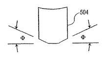
図7A〜図7Dは、本発明の一実施形態によりシリコンウェーハに溝を機械加工するために使用されるダイシングソーブレードの形状を示す。図7Aでは、第1のダイシングソーブレード502は、すべての製造プロセスが完了した後の手術刀に実質的にもたらされる角度となる角度Φを示す。図7Bは、それぞれが切削角Φを示す2つの傾斜した切削面を持った第2のダイシングソーブレード504を示す。図7Cは、同様に切削角Φを有するが第1のダイシングソーブレード502とはわずかに異なる形状を持った第3のダイシングソーブレード506を示す。図7Dは、図7Bと同様それぞれ切削角Φを示す2つの傾斜した切削面を持った第4のダイシングソーブレード508を示す。
7A-7D illustrate the shape of a dicing saw blade used to machine grooves in a silicon wafer according to one embodiment of the present invention. In FIG. 7A, the first dicing saw
図7A〜図7Dの各ダイシングソーブレード502,504,506および508は、それぞれ同一の切削角Φを有するが、切削角をシリコンベースの手術刀の様々な用途のために様々に異ならせることができることは当該分野の技術者には明らかである。さらに、以下に述べるように、単一のシリコン手術刀は、様々な角度を有する様々な切れ刃を有することができる。第2のダイシングソーブレード504は、特定の設計のシリコンベースの手術刀の製造能力を高めるため、または2つまたは3つの切れ刃を有するシリコン手術刀を製作するために使用することができる。図20A〜図20Gを参照しながらブレード設計の様々な例を詳細に説明する。本発明の好ましい実施形態では、ダイシングソーブレードをダイヤモンドグリットソーブレードとする。
Each of the dicing saw
シリコンウェーハ202の第1の面304に溝を機械加工するため、特別のダイシングソーブレードが使用される。このダイシングソーブレードの形状は、許容可能な磨耗耐用年数を維持しながら最高の表面仕上げが得られるように、特別に選択される。ダイシングソーブレードの刃先は、シリコンウェーハ202に得られる溝を形づくるプロファイルを持った形状である。この形状は、得られるブレードの斜面形状に対応する。例えば、手術刀は通常、片面傾斜ブレードの場合、15°〜45°の刃先斜面角を有し、両面傾斜ブレードの場合には15°〜45°の半分の刃先斜面角を有する。ダイシングソーブレードをエッチング条件に関連付けて選択することにより、斜面角が精密に制御される。
A special dicing saw blade is used to machine the grooves in the
図8は、本発明の一実施形態により支持体に取り付けられたシリコンウェーハを貫通するダイシングソーブレードの動作を示す。図8は、シリコンウェーハ202の第1の面304に溝を機械加工するダイシングソーブレード機械の動作を示す。この例では、シリコンベースの手術刀の刃先を製作するため、図7A〜図7D(502,504,506または508)のダイシングソーブレードの何れかを使用することができる。図7A〜図7Dのブレード形状以外にも、ダイシングソーブレード用に作ることができる形状もあることを理解すべきである。図9は、テープに取り付けられたシリコンウェーハに溝を機械加工する本発明の一実施形態によるダイシングソーブレードの断面図を示す。図9は、実際にシリコンウェーハ202を貫通する図8に示したものと同じダイシングソーブレードアセンブリの拡大断面図を示す。ダイシングソーブレード502がシリコンウェーハ202を完全に貫通しないことが分かるが、片面傾斜切削の場合、シリコンウェーハ202の厚さの約50〜90%まで貫入する。これは、片面傾斜の溝を機械加工(または熱間鍛造により成形)するために採用される如何なる方法にも当てはまる。任意のダイシングソーブレードまたは任意の機械加工方法による両面傾斜切削の場合も、シリコンウェーハ202の厚さの約25〜49%がシリコンウェーハ202のそれぞれの面で機械加工により除去される(または成形される)。図10Aおよび図10Bは、本発明の一実施形態により製作された片面傾斜の切れ刃を有するシリコン手術刀および両面傾斜の切れ刃を有するシリコン手術刀をそれぞれ示している。
FIG. 8 illustrates the operation of a dicing saw blade that passes through a silicon wafer attached to a support according to one embodiment of the present invention. FIG. 8 illustrates the operation of a dicing saw blade machine that machines grooves in the
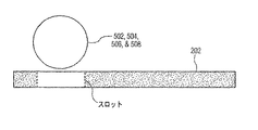
上述したように、特に溝を機械加工するためにダイシングソーブレードを使用する場合、シリコンウェーハにスロットを刻設することが可能である。スロットは、基準貫通穴と同様にして、すなわちレーザウォータジェットまたはエキシマレーザでシリコンウェーハ202に刻設することができるが、全く異なる役割を果たす。シリコンウェーハ202を溝加工機械に正確に位置決めするため、基準貫通穴が溝加工機械によって用いられたことを思い出されたい。これは、両面傾斜ブレードを作る場合に特に有用である。というのも、適切な両面傾斜ブレードを確実に製造するため、(シリコンウェーハ202の裏面に対する)第2の機械加工を正確に位置決めしなければならないからである。しかし、スロットは別の目的で使用される。このスロットにより、ダイシングソーブレードは、シリコンウェーハ202を分裂または破断させずに(図8に示すように)その縁部から切り離すことを開始することが可能になる。図8Aに示すように、これが好ましい実施形態である。図8を参照すると、スロットを使用せず溝を図示のように機械加工する場合、機械加工された溝に沿った領域ではシリコンウェーハは非常に薄く小さな応力で破断される可能性があるため、機械加工されたシリコンウェーハ202がそれらの領域で破断されやすいことは明らかである。すなわち、図8の機械加工されたシリコンウェーハは、構造的な剛度に欠ける。これを図8Cのシリコンウェーハと比較する。図8Cの機械加工されたシリコンウェーハ202は、はるかに剛性が高く、製造スループットを向上させる。図8Cにより機械加工されたシリコンウェーハ202の方が図8のそれに比べて破断される可能性が少ない。図8Aおよび図8Bに示すように、スロットは、ダイシングソーブレードよりも幅広にされ、適切な深さで機械加工を開始することができるようダイシングソーブレードを差し込むことが十分可能となる長さにされる。従って、ダイシングソーブレードが下に向かって動く間は、シリコンウェーハ202に分裂および破断を生じる切削を行わず、ダイシングソーブレードが水平に動く場合、そのように切削を開始するように設計されている。図8Cは、シリコンウェーハ202の第1の面に対して機械加工された一連のスロットおよび溝を示す。
As mentioned above, it is possible to engrave slots in a silicon wafer, especially when using a dicing saw blade to machine grooves. The slot can be carved into the
図11は、シリコンウェーハに溝を機械加工するために用いられる本発明の一実施形態によるレーザシステムのブロック図を示す。以下に詳細に説明するように、溝は、図12を参照して説明するような超音波で機械加工することが可能である。これら2つの方法の利点は、半月形ブレード,スプーンブレードおよび強膜切開ブレードなど、非直線状の複雑な切れ刃プロファイルでブレードを作ることができることである。図11は、単純化されたレーザ機械アセンブリ900を示す。レーザ機械アセンブリ900は、レーザビーム904を放射するレーザ902および基台908に搭載された多軸制御機構906を具えている。もちろん、レーザ機械アセンブリ900は、コンピュータおよび場合によってはネットワークインターフェースを具えることもできるが、理解を容易にするために省略する。
FIG. 11 shows a block diagram of a laser system according to an embodiment of the invention used to machine grooves in a silicon wafer. As will be described in detail below, the grooves can be machined with ultrasound as described with reference to FIG. The advantage of these two methods is that the blades can be made with complex, non-linear cutting edge profiles, such as a meniscus blade, a spoon blade and a scleral blade. FIG. 11 shows a simplified
レーザ機械アセンブリ900で溝を機械加工する場合、多軸制御機構906によって操作されるようにすることができる取り付けアセンブリ204に、シリコンウェーハ202が取り付けられる。レーザ加工アセンブリ900および様々な光ビームマスキング技術を用いることにより、1列のブレードプロファイルを機械加工することができる。光ビームマスクはレーザ902の内部に配置され、入念な設計により、レーザ902が意図されない場所でシリコン材料を除去しないように妨げる。両面傾斜ブレードの場合、反対側の面がプレカットされた面取り部206A,206Bまたは位置合せ用の基準406を使用する同じ方法で機械加工される。
When machining grooves with the
レーザ902は、等方性ウェットエッチングステップに備え、シリコンウェーハ202の第1の面304または第2の面306の何れかに、溝パターン(レーザの使用に関して「除去プロファイル」とも呼ぶ)を正確かつ精密に機械加工するために使用される(図1のステップ1018を参照して詳細に説明する)。多軸制御および内部レーザ光ビームマスクの使用は、シリコンウェーハ202の上記除去プロファイルをラスタするために用いられる。その結果、手術刀製品に必要とされる傾斜に対応する浅い角度の付いた傾斜を持った輪郭の溝が得られる。このプロセスにより、様々な曲線プロファイルパターンを実現することができる。この機械加工ステップに利用可能である複数のレーザの種類がある。例えば、エキシマレーザまたはレーザウォータジェット402を使用することができる。エキシマレーザ902の波長は157nmから248nmの範囲とすることができる。その他の例として、YAGレーザおよび355nmの波長を有するレーザが挙げられる。もちろん、溝パターンを機械加工するために150nmから11000nmの範囲内のある波長を有するレーザビームを使用することができることを当該分野の技術者は理解することができる。
図12は、シリコンウェーハに溝を機械加工するために用いられる本発明の一実施形態による超音波加工システムのブロック図を示す。超音波加工は、精密に機械加工された超音波工具104を使用して行われ、工具104は、研磨スラリ102を用いてシリコンウェーハ202の第1の面304または第2の面306を機械加工するために使用される。この機械加工は、一度に片面に対して行われる。両面傾斜ブレードの場合、位置合せのための基準貫通穴406を用いた同じ方法で反対側の面が機械加工される。
FIG. 12 shows a block diagram of an ultrasonic processing system according to one embodiment of the present invention used to machine grooves in a silicon wafer. Ultrasonic machining is performed using a precision machined
超音波加工は、等方性ウェットエッチングに備え、シリコンウェーハ202の表面に溝パターンを正確かつ精密に機械加工するために用いられる。超音波加工は、マンドレル/工具104を超音波で振動させることにより行われる。工具104は、シリコンウェーハ202と接触しないが、シリコンウェーハ202の非常に近位にあり、また工具104から放出される超音波の動作によって研磨スラリ102を励振させる。工具104によって放出される超音波は、研磨スラリ102に機械加工された工具104の対応するパターンにてシリコンウェーハ202を侵食させる。
Ultrasonic machining is used to machine the groove pattern accurately and precisely on the surface of the
フライス加工,研削または放電加工(EDM)により工具104を機械加工して溝パターンを作る。機械加工されたシリコンウェーハ202に得られるパターンは、工具104に機械加工されたパターンと対応する。エキシマレーザよりも超音波加工方法を用いることの利点は、シリコンウェーハ202の片面全体が、超音波加工される多数のブレード溝パターンを同時に有することができることである。従って、このプロセスは迅速であって比較的安価である。また、エキシマレーザ加工プロセスと同様、このプロセスにより様々な曲線プロファイルパターンを得ることできる。
The
図13は、シリコンウェーハに溝を形成するために用いられる本発明の一実施形態による熱間鍛造システムの図を示す。溝の形状をウェーハ表面に熱間鍛造することができる。このプロセスは、ウェーハを鍛造可能な状態に加熱することを利用する。続いてウェーハの表面は、結果的に得られる溝のパターンを反転させたものを組み込んだ2つの金型の間でプレスされる。 FIG. 13 shows a diagram of a hot forging system according to one embodiment of the present invention used to form grooves in a silicon wafer. The groove shape can be hot forged on the wafer surface. This process utilizes heating the wafer to a forgeable state. The surface of the wafer is then pressed between two molds that incorporate an inverted version of the resulting groove pattern.
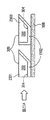
シリコンウェーハ202は、加熱チャンバ内で予備加熱するか、シリコンウェーハ202がその上に搭載される、加熱された基部部材1054の動作によって完全に加熱することができる。高温で充分な時間が経過した後、シリコンウェーハ202は鍛造可能となる。次いで、加熱された金型1052が加熱された金型1052の反転図をシリコンウェーハ202の第1の面304に型押しするのに十分な圧力でシリコンウェーハ202へと押し下げられる。金型1052の設計は、実質的に考えられる如何なるブレード設計をも作り出すための様々な斜面角,深さ,長さおよびプロファイルの多数の溝を存在させるようにすることができる。図13に示す図は、熱間鍛造プロセスの関連する特徴をはっきりと示すため、著しく単純化および誇張してある。
The
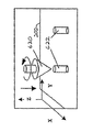
図26〜図29は、結晶性材料に直線状または非直線状の溝を機械加工するために本発明の一実施形態によるルータを使用するステップを示している。図26では、シリコンウェーハ202に貫通穴622が穿設されている。本発明の好ましい実施形態では、貫通穴622は、微小割れを防止するために必要である。上記のように、数多くの方法の中でも、ドリル,超音波加工,レーザまたはレーザウォータジェットの使用を含む複数の様々な方法のうちの1つを用いて貫通穴622をウェーハ202に作ることができる。貫通穴622の数は、シリコンウェーハ202に形成されるブレードの総数によって決まる。一般に、(ルータ加工を開始および終了するため)各ブレード毎に少なくとも2つの貫通穴622が必要である。ただし、本発明の諸実施形態はいかなる数の貫通穴622にも限定されない。
FIGS. 26-29 illustrate the steps of using a router according to an embodiment of the present invention to machine a linear or non-linear groove in a crystalline material. In FIG. 26, a through
シリコンウェーハ202に所望の貫通穴622をすべて穿設した後、ルータ620(上から見た場合に反時計回りの回転を示す)が、一定の回転速度まで上がった後、貫通穴622へと下ろされる。ルータ620は、ソフトウェア制御により所望の深さまで下ろされ所望の方向に動かされる。図27を参照されたい。ソフトウェア制御は、ルータ620が下ろされる(かつルータ加工が完了すると上げられる)深さ,シリコンウェーハ202に対してルータ620が移動するX−Y方向およびこれがX−Y方向に移動する速さを制御する。ルータ620の幾何学形状は、将来的なブレード形状に必要とされる傾斜角によって設定される。例えば、特定の目的に使用される手術刀は、特定の設計であると共に特定の刃先角を有するブレードを必要とする可能性がある。図28は、ルータ620がシリコンウェーハ202をルータ加工する場合に作り出す傾斜を示す。例えば、両面傾斜のブレードが30°の包囲角を必要とする場合、ルータ角度は150°となるはずである。
After all desired through
ルータ620の使用によってシリコンウェーハ202に直線状および非直線状の溝を形成するための比較的安価な手段が提供される。図29から分かるように、単一ブレードは、直線状部分も非直線状部分も有することができる。溝を製作するために単一の安価な工具を使用することで、ブレード製造プロセスの時間および費用を節約することができ、これによって製造および販売コストが低減される。
The use of
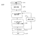
図30は、結晶性材料に直線状または非直線状の溝を本発明の一実施形態によってルータ加工するための方法の工程図を示している。ステップ604で、別個の機械加工プロセスにより、必要とされる数の貫通穴622がシリコンウェーハ202に形成される。ステップ606で、ルータ620は所望の回転速度まで上げられた後、第1の貫通穴622へと所望の深さまで挿入される。次いでソフトウェア制御が続行し、指定のパターンに従ってルータ620を動かし、所望の斜面角および設計の溝を作る(ステップ608)。ルータが最後の貫通穴622に達すると、ソフトウェア制御は、ルータ620を引き上げることを可能にする(ステップ610)。このプロセスは、シリコンウェーハ202に最適な数のブレードを製作するのに必要な回数だけ繰り返すことができる(ステップ612)。
FIG. 30 shows a process diagram of a method for routering a linear or non-linear groove in a crystalline material according to an embodiment of the present invention. At
溝を機械加工するための複数の方法について説明してきたが、再び図1に注意を向ける。シリコンウェーハ202の第1の面304に溝を機械加工するステップ1008に続き、決定ステップ2001にてシリコンウェーハ202を被覆するか否かの決定を下さなければならない。図14は、本発明の一実施形態により機械加工された溝を両面に有するシリコンウェーハおよび機械加工された面の一方に施された被膜を示す。被膜を施す場合、本発明の分野の技術者に知られた多くの技法のうちの1つに従い、ステップ2002にてシリコンウェーハ202の第1の面304に被膜1102を施すことができる。被膜1102は、エッチング制御を容易にするため、かつ得られるブレードの刃先にさらなる強度をもたらすために与えられる。シリコンウェーハ202が堆積チャンバ内に置かれ、そこでシリコンウェーハ202の、平坦な領域および溝が形成された領域の両方を含めて第1の面304全体が、窒化シリコン(Si3N4)の薄膜で被覆される。その結果得られる被膜1102の厚さは、10nmから2μmの範囲とすることができる。被膜1102は、シリコン(結晶質)ウェーハ202よりも硬い如何なる材料であってよい。具体的には、被膜1102はまた、窒化チタン(TiN),窒化アルミニウムチタン(AlTiN),二酸化シリコン(SiO2),炭化シリコン(SiC),炭化チタン(TiC),窒化ボロン(BN)またはダイヤモンド様結晶(DLC)とすることができる。両面傾斜手術刀用の被膜は、図18Aおよび図18Bを参照しながら、以下でより詳細に再び説明する。
Having described a number of methods for machining the grooves, attention is again directed to FIG. Following the
任意のステップ2002で被膜1102を施した後、次のステップは、取り外しおよび再取り付けステップ2003である(被膜を施さない場合、ステップ2003はまたステップ1008に続く)。ステップ2003で、同一の標準的な取り付け機械を利用し、シリコンウェーハ202がテープ308から取り外される。この機械は、紫外(UV)線をUV感応テープ308に照射してその粘着力を低減させることによって、シリコンウェーハ202を取り外す。UV感応テープの代わりに、低粘着性または熱剥離テープを使用することができる。UV光で充分に露光した後、シリコンウェーハ202はテープ取り付け部から簡単に持ち上げることができる。次に、第2の面306に溝を機械加工するための準備中に、第2の面306を上に向けてシリコンウェーハ202を再び取り付ける。
After applying the
次に、ステップ2004をシリコンウェーハ202に対して行う。ステップ2004では、両面傾斜のシリコンベースの手術刀を作るため、ステップ1008で行ったようにシリコンウェーハ202の第2の面306に溝を機械加工する。図15は、テープに取り付けられたシリコンウェーハ202に第2の溝を機械加工する本発明の一実施形態によるダイシングソーブレード502の断面図を示す。もちろん、シリコンウェーハ202に第2の溝を機械加工するため、エキシマレーザ902,超音波加工工具100または熱間鍛造プロセスを使用することができる。シリコンウェーハ202の第2の面306に第2の溝を機械加工するダイシングソーブレード502を図15に示す。ステップ2002で任意に施された被膜1102を示している。図10Aおよび図10Bは、それぞれ片面および両面傾斜の切削部を示している。図10Aでは、シリコンウェーハ202に単一の切削部が作られ、シングルブレードアセンブリに切削角Φがもたらされる。図10Bでは、シリコンウェーハ202に(上記の溝機械加工プロセスのうち何れかによって)第1の溝と同じ角度を持った第2の溝が機械加工されている。この結果、切削角Φを示す各切れ刃を有すると共に2Φの両面傾斜角を持つ両面傾斜のシリコンベースの手術刀がもたらされる。両面に溝が機械加工された本発明の一実施形態によるシリコンウェーハの断面像を図16に示す。
Next,
図31A〜図31Cは、本発明の一実施形態により製造された両面傾斜複数ファセットのブレードを示す。両面傾斜複数ファセットのブレード700の上側斜視図を図31Aに示す。両面傾斜複数ファセットのブレード700は、以下で説明する方法により製造された4つのファセットを有するブレードである。角度θ1は第1の組のファセット704a,704bの刃先斜面角を示し、角度θ2は第2の組のファセット704cおよび704dの刃先斜面角を示す。
FIGS. 31A-31C show a double-sided inclined multi-faceted blade made according to one embodiment of the present invention. A top perspective view of a double-sided inclined
両面傾斜複数ファセットのブレード700に示す斜面およびファセットは、上記の如何なる溝製作方法にて製造することができる。例えば、両面傾斜複数ファセットのブレード700に溝を機械加工して斜面を形成するため、レーザ904を使用することができる。レーザビーム904は、ウェーハの第1の面に第1の溝を機械加工するために第1の通路を作り、第1の溝を機械加工し、次いで第2の溝を機械加工するために適当な間隔で配置された第2の通路を作ることができる。同様に、第1の複数斜面のブレード700は、図13に関してさらに詳細に説明する熱間鍛造プロセスで製作することができる。さらに、複数の溝を機械加工し、図31A〜図31Cに示すような両面傾斜複数ファセットのブレード700を形成するため、溝を機械加工する上記の如何なる方法を使用することができる。
The slope and facet shown in the double-sided
図32Aに、斜面角変化両面傾斜ブレード702の上側斜視図を示す。斜面角変化両面傾斜ブレード702は、本明細書で説明する方法によって製造することができる。角度θ4は、はじめブレード先端で鈍く、肩に向かってより鋭くなって角度θ3となる。この設計により、斜面角変化両面傾斜ブレード702の鋭利な尖端が強化される。
FIG. 32A shows an upper perspective view of the inclined angle changing double-sided
斜面角変化両面傾斜ブレード702に示した斜面は、上記の如何なる溝加工方法にて作ることができる。例えば、溝を機械加工して斜面角変化両面傾斜ブレード702に斜面を形成するため、レーザビーム904を使用することができる。ソフトウェアプログラム制御に従って結晶質材料を機械加工することによって可変斜面を製作するため、レーザビーム904を調整することができる。同様に、第1の複数斜面ブレード700は、図13に関してより詳細に説明する熱間鍛造プロセスで製作することもできる。さらに、複数の溝を機械加工して、図32A〜図32Cに示すような斜面角変化両面傾斜ブレード702を形成するため、溝を機械加工するための上記いかなる方法を使用することもできる。図32Bおよび図32Cは、斜面角Φ3およびΦ4が斜面角変化両面傾斜ブレード702上で、先端からの距離に従ってどのように変わるかを示す、斜面角変化両面傾斜ブレード702の2つの側部斜視図を示す。
The slope shown in the slope angle changing double-sided
図20Bおよび図20Dもまた、複数の斜面角を付けて製造することができる複数切れ刃のブレードの上側斜視図を示す。本明細書で説明する方法は、例えば図20Bおよび図20Dに示すものなど、それぞれの切れ刃が異なる斜面角を有するブレードを製造することができる。図20Bおよび図20Dでは、4つの切れ刃があり、それぞれの切れ刃は異なる片斜面角または両斜面角を有することができる。さらに、各斜面角は、上記のように1つまたは2つのファセットを有することができる。これらは例示目的で示すに過ぎず、本明細書に記載される本発明の実施形態を限定するものではない。 20B and 20D also show a top perspective view of a multi-edged blade that can be manufactured with multiple bevel angles. The methods described herein can produce blades with different cutting edges, such as those shown in FIGS. 20B and 20D, for example. 20B and 20D, there are four cutting edges, and each cutting edge can have a different single bevel angle or both bevel angles. Furthermore, each bevel angle can have one or two facets as described above. These are given for illustrative purposes only and are not intended to limit the embodiments of the invention described herein.
溝機械加工ステップ2004に続き、両面に溝が機械加工されたシリコンウェーハ202をステップ1018でエッチングするか、両面に溝が機械加工されたシリコンウェーハ202をステップ1016でダイシングするかを、ステップ2005で決定しなければならない。ダイシングステップ1016は、ダイシングソーブレード,レーザビーム(例えばエキシマレーザまたはレーザウォータジェット402)により行うことができる。ダイシングによって得られるストリップを(以下で詳細に説明する)ウェーハボートの代わりに特注の取り付け具で(ステップ1018で)エッチングすることが可能になる。
Following the
図17Aおよび図17Bは、両面に溝が機械加工されたシリコンウェーハに対して行われる本発明の一実施形態による等方性エッチング処理を示す。エッチングステップ1018で、機械加工されたシリコンウェーハ202がテープ308から取り外される。次いでシリコンウェーハ202はウェーハボートに配置され、等方性の酸浴槽1400内に浸漬される。エッチング剤1402の温度,濃度および攪拌は、エッチング処理の均一性が最大限になるように制御される。使用される好ましい等方性エッチング剤1402は、フッ化水素酸,硝酸,酢酸(HNA)からなる。同じ目的を達成するため、その他の組合せおよび濃度を用いることができる。例えば、水を酢酸で置き換えることができる。同じ結果を実現するため、スプレーエッチング,等方性二フッ化キセノンガスエッチングおよび電解エッチングを浸漬エッチングの代わりに用いることもできる。ガスエッチングに使用することができる化合物の別の例は、六フッ化硫黄またはその他の類似のフッ化ガスである。
17A and 17B show an isotropic etching process according to one embodiment of the present invention performed on a silicon wafer with grooves machined on both sides. In an
エッチング処理では、シリコンウェーハ202の両面およびそれぞれの溝を対向する溝プロファイルが交わるまで均一にエッチングする。これが起こった時点でシリコンウェーハ202はエッチング剤1402から直ちに取り出され、水洗される。このプロセスによって得られる切れ刃の期待半径は、5nmから500nmである。
In the etching process, both surfaces of the
等方性化学エッチングは、シリコンを均一に除去するために用いられるプロセスである。本発明の一実施形態による製造プロセスでは、上記の機械加工で製作されたウェーハの表面プロファイルは、ウェーハの反対側の面のプロファイルと交わるまで(片面傾斜ブレードが望ましい場合、機械加工されていないシリコンウェーハの反対側の表面と交わるまで)均一に下げられる。等方性エッチングは、ブレードの角度を保ちながら所望のブレードの鋭利度を実現するために使用される。所望の刃先形状は、機械加工の機械的および熱的な力に耐えるには繊細すぎるので、機械加工のみでウェーハのプロファイルを交わらせようとすると失敗する。等方性エッチング剤(エッチング剤)1402の各酸性化合物はそれぞれ、等方性の酸浴槽1400内で特定の機能を有する。まず硝酸が露出したシリコンを酸化させ、次にフッ化水素酸が酸化したシリコンを除去する。酢酸はこのプロセス中、希釈液として作用する。再現可能な結果を得るため、組成,温度および攪拌を精密に制御する必要がある。
Isotropic chemical etching is a process used to remove silicon uniformly. In the manufacturing process according to one embodiment of the present invention, the surface profile of the wafer fabricated by the above machining is not crossed with the profile of the opposite surface of the wafer (if a single-sided inclined blade is desired, unmachined silicon Until it meets the opposite surface of the wafer). Isotropic etching is used to achieve the desired blade sharpness while maintaining blade angle. The desired cutting edge shape is too delicate to withstand the mechanical and thermal forces of machining, so attempts to cross the wafer profile by machining alone will fail. Each acidic compound of the isotropic etching agent (etching agent) 1402 has a specific function in the
図17Aでは、被膜1102なしのシリコンウェーハ202が等方性エッチング浴槽1400内に配置されている。第1の手術刀1404,第2の手術刀1406,第3の手術刀1408の各ブレードは、それぞれ相互につながっていることに留意されたい。エッチング剤1402がシリコンに作用する場合、時間が経過に伴って分子の層が1つ1つ除去され、(第1の手術刀1404の)2つの角度1410および1412が次の手術刀(第2の手術刀1406)との接合点で交わるまで、シリコン(すなわち手術刀)の幅を減少させる。この結果として、複数の手術刀(1404,1406および1408)が形成される。エッチング剤1402によって溶解されて行くため、シリコン材料の残りが少なくなるが、等方性エッチング処理全体を通して同一の角度が維持されることに留意されたい。
In FIG. 17A, a
図18Aおよび図18Bは、溝が両面に機械加工され、片面が被膜層であるシリコンウェーハに対する本発明の一実施形態による等方性エッチング処理を示す。図18Aおよび図18Bでは、エッチング処理がシリコンウェーハ202の第2の面306上でのみ作用するように、テープ308および皮膜1102がシリコンウェーハ202に残されている。エッチング処理中にウェーハをテープに取り付けておく必要はなく、これは製造上の任意選択である過ぎない。この場合も、等方性エッチング材料1402は露出したシリコンウェーハ202にのみ作用し、シリコン材料を(1層ずつ)除去するが、(これは第2の面306であるので)ステップ2004で機械加工されたのと同じ角度を維持する。その結果として、図18Bで、シリコンベースの手術刀1504,1506および1508は、第1のテープ308および任意選択の被膜1102があるため第1の面304に対し、また等方性エッチング剤1402は機械加工された溝の表面に沿ってシリコン分子の層を均等に除去するので第2の面306に対し、ステップ1008および2004で機械加工されたのと同じ角度を有する。シリコンウェーハ202の第1の面304は全くエッチングされず、完成したシリコンベースの手術刀にさらなる強度を与える。
18A and 18B show an isotropic etching process according to one embodiment of the present invention for a silicon wafer with grooves machined on both sides and one side being a coating layer. 18A and 18B, the
シリコンウェーハ202の第1の面304に被膜1102を施す選択的なステップ2002を用いる別の利点は、切れ刃(溝が機械加工された第1の面)が、ベースのシリコン材料よりも強い材料特性を有する(好ましくは窒化シリコンの層からなる)被膜1102からなることである。従って、被膜1102を施すプロセスによって、より強くより耐久性の高い切れ刃がもたらされる。被膜1102はまた、ブレードの表面に磨耗保護を与える。これは、電気機械的に往復運動をするブレード装置の鋼と接触するブレードにとって望ましい。表Iは、被膜1102なし(シリコン)および被膜1102有り(窒化シリコン)で製造された、シリコンベースの手術刀の強度を示す典型的な仕様を表す。
Another advantage of using the

ヤング係数(弾性率とも呼ばれる)は、材料固有の剛性の測定値である。この係数が高いほど材料は剛度が高い。耐力強度は、荷重をかけられた材料が弾性変形から塑性変形に移行する点である。すなわちこれは、その点で材料がもはや撓まず、永久に曲がるまたは破損するという点である。(被膜1102有りまたはなしで)エッチングした後で、エッチングされたシリコンウェーハ202を完全に水洗および清浄化し、残存するエッチング剤1402の薬品をすべて除去する。
Young's modulus (also called elastic modulus) is a measure of the inherent stiffness of the material. The higher this coefficient, the higher the stiffness. Yield strength is the point at which a loaded material transitions from elastic deformation to plastic deformation. This means that at that point the material no longer bends and will bend or break permanently. After etching (with or without coating 1102), the etched
図19は、本発明の一実施形態に従って製造された片面に被膜を有する両面傾斜のシリコン手術刀の結果的に得られた切れ刃を示す。切れ刃1602は通常、ダイヤモンド手術刀の半径と同様の5から500nmの半径を有するが、はるかに低いコストで製造される。ステップ1018のエッチングステップを行った後、ステップ1002およびステップ2003の取り付けステップと同じステップ1020により、シリコンベースの手術刀を取り付けることができる。
FIG. 19 shows the resulting cutting edge of a double-sided tilted silicon surgical knife with a coating on one side made according to one embodiment of the present invention. The
取り付けステップ1020に続き、ステップ1022でシリコンベースの手術刀(シリコンブレード)を別々にする、すなわちダイシングソーブレード,レーザビーム(例えばレーザウォータジェット402またはエキシマレーザなど)またはシリコンブレードを互いに分離させるためのその他の適当な手段を用い、各シリコンブレードを別々に切断することができる。当該分野の技術者には理解されるように、150nmから11000nmの範囲内の何れかの波長を有するレーザを使用することもできる。この波長の範囲内のレーザの一例はエキシマレーザである。レーザウォータジェット(YAGレーザ)の特異性は、ウェーハの曲線状の途切れたパターンをなぞることができることである。これにより、切れ刃のないブレードプロファイルを実質的に数限りなく製作するための融通性が製造業者にもたらされる。レーザウォータジェットは、水流を導波路として用い、それによりレーザが帯のこのように切削することを可能にする。これは、上記のように連続的な直線パターンしかダイシングできない現時点における技術状態のダイシング機械では実現することができない。
Following the
顧客の特定の要望に従い、ステップ1024にて別々にされた外科用シリコンブレードを精選し、ブレードの柄アセンブリに配置する。ただし、実際に「精選および配置」する前に、エッチングされた(テープおよびフレームまたはテープ/ウェーハのフレームに取り付けられた)シリコンウェーハ202は、テープ308の粘着力を低減させるため、ウェーハ取り付け装置にて紫外線(UV)光により照射される。依然「粘着力低減」テープおよびフレームまたはテープ/ウェーハのフレームにあるシリコンウェーハ202が市販のダイ接着組立システム内に装填されている。いくつかのステップの順番は様々な製造環境によって相互交換することができるという上述したことを想起されたい。このような一例は、個別化ステップおよびUV光による照射である。これらのステップは、必要に応じて相互に交換することができる。
According to the customer's specific needs, the surgical silicon blades separated at
ダイ接着剤組立システムは、エッチングされた個別のシリコン手術刀を「粘着力低減」テープおよびウェーハまたはテープ/ウェーハのフレームから取り外し、これらシリコン手術刀を所望の公差内の別々のホルダにそれぞれ取り付ける。2つの構成要素を取り付けるため、エポキシまたは接着剤を使用する。シリコン手術刀をそれぞれの基板に取り付けるため、熱かしめ,超音波かしめ,超音波溶着,レーザ溶着または共晶接合を含むその他の組み立て方法を用いることができる。最後にステップ1026にて柄付きの完全に組み立てられたシリコン手術刀をシリコン手術刀の設計に従い、不燃性および安全性を保証するために包装して使用のために輸送する。
The die adhesive assembly system removes individual etched silicon surgical knives from the “reducing adhesive” tape and wafer or tape / wafer frame and attaches each of these silicon surgical knives to separate holders within the desired tolerances. Epoxy or adhesive is used to attach the two components. Other assembly methods including heat caulking, ultrasonic caulking, ultrasonic welding, laser welding or eutectic bonding can be used to attach the silicon surgical knife to each substrate. Finally, in
手術刀をそのホルダに取り付けるために使用される別の組立方法は、スロットの別の使い方に関する。上述したように、スロットはレーザウォータジェットまたはエキシマレーザによって作ることができ、溝の機械加工時にダイシングソーブレードをシリコンウェーハ202に係合させるための開口を設けるために用いた。スロットのさらなる使用法として、ホルダ内の1つ以上のポストに対する受口をブレードに設けることができる。図24は、このような形状を示す。図24では、完成した手術刀2402が、そのホルダ係合領域2406に作られた2つのスロット2404a,2404bを有する。これらは、ブレードホルダ2410のポスト2408a,2408bと係合する。これらのスロットは、製造プロセスのどの時点でもシリコンウェーハ202に刻設することができるが、手術刀を別々にする単一化よりも前に刻設可能であることが好ましい。係合させる前に、適切な領域に接着剤を塗布して緊密な保持を保証することができる。次いで、完成製品に完成された外見をもたらすため、カバー2412を図示の様に接着することができる。ポスト−スロットアセンブリを行う目的は、これによってブレード2402が切断処理中に受ける可能性がある何らかの引張力に対するさらなる耐性をもたらすことである。
Another assembly method used to attach the surgical knife to its holder relates to another use of the slot. As described above, the slot could be made by a laser water jet or excimer laser and was used to provide an opening for engaging the dicing saw blade with the
両面傾斜のシリコンベース手術刀の製造プロセスを説明してきたが、片面傾斜の手術刀をシリコンで製造する本発明の第2の実施形態による方法の工程図を示す図2に注目する。図1の1002,1004,1006,1008は、図2に示す方法と同じであり、従ってその説明は繰り返さない。しかし、片面傾斜手術刀の製造方法は、次のステップであるステップ1010では両面傾斜ブレードの製造方法と異なっているため、詳細に説明する。
Having described the manufacturing process for a double-sided tilted silicon-based surgical knife, attention is now directed to FIG. 2, which shows a process diagram of a method according to a second embodiment of the present invention for manufacturing a single-sided tilted surgical knife with silicon. 1002, 1004, 1006, 1008 in FIG. 1 are the same as the method shown in FIG. However, the method for manufacturing a single-sided inclined surgical knife is different from the method for manufacturing a double-sided inclined blade in
ステップ1008に続き、決定ステップ1010は、機械加工されたシリコンウェーハ202をシリコンウェーハ取り付けアセンブリ204から取り外すかどうかを決定する。単一溝のシリコンウェーハ202を(ステップ1012で)取り外す場合のさらなる選択肢は、ステップ1016で単一溝ウェーハをダイシングすることである。任意選択の取り外しステップ1012で、シリコンウェーハ202を同一の標準的な取り付け機械を使用してテープ308から取り外す。
Following
シリコンウェーハ202をステップ1012で取り外す場合、ステップ1016にてシリコンウェーハ202を任意選択でダイシングする(すなわちシリコンウェーハ202を帯状に切り離す)ことができる。ダイシングステップ1016は、ダイシングブレード,エキシマレーザ902またはレーザウォータジェット402により行うことができる。ダイシングによって得られるストリップを(以下で詳細に説明する)ウェーハボートの代わりに特注の取り付け具で(ステップ1018で)エッチングすることが可能になる。1016のダイシングステップ,1012の取外しステップまたは1008の溝機械加工ステップに続く片面傾斜シリコンベース手術刀製造方法の次のステップは、ステップ1018である。このステップ1018は、すでに上述したエッチングステップである。その後、ステップ1020,1022,1024および1026が続くが、これらはすべて両面傾斜シリコンベース手術刀の製造を参照しながら詳細に上述したので、再び説明する必要はない。
If the
図3は、片面傾斜手術刀をシリコンで製造する本発明の第3の実施形態による代替方法の工程図を示す。図3に示した方法は、ステップ1002,1004,1006,1008を通し、図2で示したものと同じである。ただし、図3のステップ1008の後に被覆ステップ2002がある。被覆ステップ2002は、図1を参照しながら先に説明したので、再び詳細に述べる必要はない。被覆ステップの結果は、上述したものと同じであり、すなわち、シリコンウェーハ202の機械加工された面は、その上に層1102を有する。
FIG. 3 shows a process diagram of an alternative method according to a third embodiment of the invention for manufacturing a single-sided inclined surgical knife from silicon. The method shown in FIG. 3 is the same as that shown in FIG. 2 through
被覆ステップ2002に続き、ステップ2003で、シリコンウェーハ202が取り外され、再び取り付けられる。このステップも、図1(ステップ2003)を参照して上述したものと同じである。この結果、シリコンウェーハ202の被覆された面が、取り付けアセンブリ204に対し下向きになる。その後、すべて上で詳細に説明したステップ1018,1020,1022,1024および1026が行われる。最終的な結果が、手術刀の強度および耐久性を向上させるための被膜1102が施された第1の面304(機械加工された面)を有する片面傾斜手術刀となる。図23Aおよび図23Bは、片面傾斜の被覆された手術刀をより詳細に示すと共に明らかにしている。
Following the
図23Aおよび図23Bは、機械加工された溝を片面に持ち、被膜層を反対側の面に持つシリコンウェーハに対する本発明のさらなる一実施形態による等方性エッチング処理を示す。上記のように、シリコンウェーハ202は第1の面304に施された被膜1102を有し、被膜1102は次いでテープ308に取り付けられ、従って図23Aに示すようにそれと密着する。次いでシリコンウェーハ202は、詳細に上述したように、エッチング剤1402が入った浴槽1400内に配される。エッチング剤1402は、シリコンウェーハ202の第2の面306(「上面」)をエッチングし始め、シリコン分子を1層ずつ除去する。ある期間後、シリコンウェーハ202の厚さは、第2の面306が第1の面304および被膜1102と接触するまでエッチング剤1402によって低減される。その結果、窒化シリコンで被覆された片面傾斜のシリコンベース手術刀が得られる。窒化シリコンを持った(または被覆した)刃先を有することの上記利点はすべて、図18A,図18Bおよび図19を参照しながら示し、説明したようなこの種類のブレードに等しく該当する。
FIGS. 23A and 23B illustrate an isotropic etching process according to a further embodiment of the present invention for a silicon wafer having a machined groove on one side and a coating layer on the opposite side. As described above, the
図20A〜図20Gは、本発明の方法に従って製造することができるシリコンベース手術刀の様々な例を示す。このプロセスを用い、様々なブレード設計を製造することができる。片面傾斜,線対称および非線対称の両面傾斜ならびに曲線状の切れ刃を持つブレードを製作することができる。片面傾斜の場合、機械加工はウェーハの片面にのみ行われる。刃先が1つのチゼル(図20A),刃先が3つのチゼル(図20B),2つの刃先が鋭利なスリット(図20C),4つの刃先が鋭利なスリット(図20D),1つの刃先が鋭利なスタブ(図20E),1つの刃先が鋭利な角膜切開刀(図20F)および曲線状の刃先が鋭利な半月形など、様々なブレードプロファイルを製作することができる。プロファイルの角度,幅,長さ,厚さおよび斜面角をこのプロセスにて変えることができる。このプロセスは、より多くの変形形態および特徴を製作するため、従来のフォトリソグラフィと組み合わせることができる。 20A-20G show various examples of silicon-based surgical knives that can be manufactured according to the method of the present invention. This process can be used to produce a variety of blade designs. Blades with single-sided slopes, line-symmetrical and non-line-symmetrical double-sided slopes and curved cutting edges can be produced. In the case of single-sided tilting, machining is performed only on one side of the wafer. One chisel (FIG. 20A), three chisel (FIG. 20B), two sharp edges (FIG. 20C), four sharp slits (FIG. 20D), one sharp edge Various blade profiles can be made, such as a stub (FIG. 20E), a keratotomy with a sharp edge (FIG. 20F), and a half-moon with a sharp edge. The angle, width, length, thickness and slope angle of the profile can be changed in this process. This process can be combined with conventional photolithography to produce more variations and features.
図21Aおよび図21Bは、本発明の一実施形態に従って製造されたシリコンの手術刀およびステンレス鋼の手術刀の側面図を倍率5000倍でそれぞれ示している。図21Aと図21Bとの差異に留意されたい。図21Aの方がはるかに滑らかでより均質である。図22Aおよび図22Bは、本発明の一実施形態により製造されたシリコン手術刀の刃先およびステンレス鋼ブレードの上面図を倍率10000倍でそれぞれ示している。この場合も、図22Aと図22Bとの差異は、本発明の一実施形態による方法の結果である前者が図22Bのステンレス鋼ブレードよりもはるかに滑らかでより均質であるということである。 FIGS. 21A and 21B show side views of a silicon surgical tool and a stainless steel surgical tool manufactured in accordance with an embodiment of the present invention at a magnification of 5000 times, respectively. Note the difference between FIG. 21A and FIG. 21B. FIG. 21A is much smoother and more homogeneous. FIGS. 22A and 22B show top views of a silicon surgical blade tip and stainless steel blade, respectively, made at a magnification of 10000 ×, made according to one embodiment of the present invention. Again, the difference between FIG. 22A and FIG. 22B is that the former, which is the result of the method according to one embodiment of the present invention, is much smoother and more homogeneous than the stainless steel blade of FIG. 22B.
図25Aおよび図25Bは、結晶質材料で製作されたブレードの刃先および本発明の一実施形態による層転化システムを持つ結晶質材料で製作されたブレードの刃先の輪郭投影図を示す。本発明の別の実施形態では、シリコンウェーハをエッチングした後、基板材料の表面を化学的に新しい材料2504に転化することが可能である。このステップはまた、「熱酸化,窒化転化」または「シリコン表面の炭化シリコン転化」ステップと呼ばれる。どの元素が基板/ブレード材料と相互作用することが可能であるかによって、その他の組成物を作り出すことができる。ブレードの表面を基板材料の化合物に転化することの利点は、新しい材料/表面(または転化層)をより硬質な切れ刃が作られるように選択できることである。しかし被膜とは異なり、エッチングステップ後のブレードの切れ刃の幾何学形状および鋭利度が維持される。図25Aおよび図25Bでは、転化処理によってシリコンブレードの深さが変化しておらず、すなわち「D1」(シリコンのみのブレードの深さ)が「D2」(転化層2504を持つシリコンブレードの深さ)と等しいことに留意されたい。
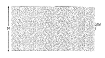
FIGS. 25A and 25B show contour projections of blade tips made of crystalline material and blade tips made of crystalline material with a layer conversion system according to one embodiment of the present invention. In another embodiment of the present invention, after etching a silicon wafer, the surface of the substrate material can be chemically converted to
図1を参照すると、ステップ1018後に、表面を転化するための決定がなされる(決定ステップ1019)。転化層が加えられる場合(選択ステップ1019からの「はい」経路)、ステップ1021にて転化層が加えられる。次いで、この方法はステップ1020に進む。転化層が加えられない場合(選択ステップ1019からの「いいえ」経路)、この方法はステップ1020に進む。転化処理は、拡散炉または高温炉を必要とする。基板は、真空状態または不活性環境中で500℃を超える温度に加熱される。選択された気体が制御された濃度で炉内に計量供給され、高温であるためシリコン中へと拡散する。シリコンに拡散するに連れ、気体はシリコンと反応して新しい化合物を形成する。被膜を施すのではなく、拡散および基板との化学反応によって新しい材料が生成されるため、シリコンブレードの元々の幾何学形状(鋭利度)が保たれる。転化処理のさらなる利点は、転化層の光学屈折率が基板のそれと異なるため、ブレードが色付きに見えることである。この色は、転化された材料の組成およびその厚さの両方によって変わる。
Referring to FIG. 1, after
表面が転化された単結晶基板材料はまた、転化されていないブレードよりも優れた耐破壊性および耐摩耗性を示す。表面をより硬質な材料に変化させることによって、基板の亀裂発生部位を形成したり結晶面に沿って劈開したりする傾向が減少する。 Single crystal substrate material with a converted surface also exhibits superior fracture and wear resistance than an unconverted blade. By changing the surface to a harder material, the tendency to form cracks in the substrate or cleave along the crystal plane is reduced.
ある程度交換可能に行うことができる製造ステップのさらなる例は、つや消し仕上げステップである。しばしば、特に手術刀の好ましい実施形態で製造する場合に、ブレードのシリコン面の反射性が非常に高くなる。これは、照明源を持った顕微鏡下でブレードを用いる場合、外科医にとって紛らわしくなる可能性がある。従ってブレードの表面に(例えば外科処置中に使用される高輝度ランプからの)入射光を拡散させるつや消し仕上げを施し、光るのではなく鈍く見えるようにすることができる。つや消し仕上げは、ブレードの表面を適当なレーザで照射し、特定のパターンおよび密度に従ってブレード表面の領域を溶融除去することによって作り出される。放出されるレーザビームの形状が通常円形であるので溶融除去領域は円形に製作されるが、必ずしもそうでなくてもよい。円形の溶融除去領域の寸法は直径25〜50μmであるが、この場合も製造者および使用するレーザの種類によって変わる。円形溶融除去領域の深さは、10〜25μmの範囲である。 A further example of a manufacturing step that can be performed to some extent interchangeable is a matte finishing step. Often the reflectivity of the silicon surface of the blade is very high, especially when manufactured with a preferred embodiment of a surgical knife. This can be confusing to the surgeon when using the blade under a microscope with an illumination source. Accordingly, the surface of the blade can be given a matte finish that diffuses incident light (eg, from a high intensity lamp used during a surgical procedure) so that it appears dull rather than shiny. A matte finish is created by irradiating the blade surface with a suitable laser and melting away areas of the blade surface according to a specific pattern and density. Since the shape of the emitted laser beam is usually circular, the melt-removal region is manufactured in a circular shape, but this is not necessarily the case. The size of the circular melt-removal region is 25-50 μm in diameter, again depending on the manufacturer and the type of laser used. The depth of the circular melt removal region is in the range of 10-25 μm.
円形溶融除去領域の「密度」とは、円形溶融除去領域で覆われる表面の割合の合計を示す。5%の「溶融除去領域密度」は、通常の滑らかで鏡面状に見えるブレードを明らかに曇らせる。ただし、すべての溶融除去領域を同じ位置に配置しても、ブレードの残りの部分の鏡面効果は影響を受けない。従って円形溶融除去領域は、ブレードの表面領域全体に無作為に適用される。実際には、凹部を無作為に配置するが特定の溶融除去領域密度およびパターンの無作為性による所望の効果を実現するグラフィックファイルを作成することができる。このグラフィックファイルは、手動またはコンピュータのプログラムによって自動的に作成することができる。実施することができるさらなる特徴は、シリアルナンバー,製造者のロゴまたは外科医の病院名をブレード自体に記入することである。 The “density” of the circular melt removal region indicates the total of the ratio of the surface covered with the circular melt removal region. A “melted zone density” of 5% clearly cloudes a normal smooth and specular blade. However, even if all the melt-removal regions are arranged at the same position, the mirror effect of the remaining part of the blade is not affected. Thus, the circular melt removal area is randomly applied to the entire surface area of the blade. In practice, a graphic file can be created that randomly arranges the recesses, but achieves the desired effect due to the specific melt removal area density and pattern randomness. This graphic file can be created manually or automatically by a computer program. A further feature that can be implemented is to fill in the blade itself with the serial number, the manufacturer's logo, or the surgeon's hospital name.
通常、ブレードにつや消し仕上げを施すため、ガントリレーザまたはガルボヘッドレーザ加工装置を使用することができる。前者は低速であるが極めて正確であり、後者は高速であるがガントリほど正確ではない。全体的に正確さは肝要ではなく、製造速度はコストに直接影響するので、ガルボヘッドレーザ機械が好ましい工具と言える。これは1秒間に数千ミリメートル動くことができ、典型的な手術刀に対して約5秒間のエッチング時間で全体的な溶融除去領域をもたらす。 Usually, a gantry laser or galvo head laser processing apparatus can be used to give the blade a matte finish. The former is slow but extremely accurate, while the latter is fast but not as accurate as the gantry. Overall accuracy is not critical and manufacturing speed directly affects cost, so a galvo head laser machine is the preferred tool. This can move thousands of millimeters per second, resulting in an overall melt removal area with an etch time of about 5 seconds for a typical surgical knife.
図33A〜図33Cは、本発明の一実施形態に従って製造される手術刀340のさらなる図を示す。図33Aに、手術刀の様々なパラメータを示す。例えば、側部切削長さ,先端−肩長さおよびプロファイル角度を示す。各パラメータの値は、ブレードの設計および期待される用途に応じて異なる。ただし、手術刀および非手術刀を製造するための方法の利点(以下で説明する)により、こうした方法に従って製造されるいくつかの手術刀のプロファイル角度は、通常、そうなるよりも小さくすることができる。図示目的のためだけであり、また限定的な意味として取られるべきではないが、本発明の一実施形態による特定のブレードプロファイルでは約60°のプロファイル角度が得られる。図33Bおよび図33Cは、上述したさらなるパラメータを示す。
33A-33C show further views of a
当該分野の技術者によく知られたさらなる工業用語およびパラメータは、ブレードの刃先半径である。「切削半径」すなわち「刃先半径」は、皮膚,目(眼科用途の場合)またはその他の材料/物質を切る鋭利な刃先の半径である。例えば、外科医が患者の目を切ったり切開したりするためにブレードを使用する場合、使用するブレードが可能な限り鋭利であることが決定的に重要でないとしても非常に重要である。図34Aおよび図34Bは、本発明の一実施形態に従って製造された手術刀の刃先半径を示す。図34Bは、図34Aのブレード350のA−A線に沿った図面である。以下で説明するような本発明の実施形態により製造される(外科用または非外科用の)ブレードは、約30nmから約60nmの範囲の刃先半径を有することができ、本発明の一実施形態では、約40nmの刃先半径を有することができる。表IIおよび表IIIは、金属ブレードの刃先半径および以下で説明する本発明の実施形態によって製造されたシリコンブレードの刃先半径の測定で蓄積された生データを示す。このデータは図35に、本明細書で説明した本発明の実施形態により製造されたブレードの刃先半径の範囲を示す第1の曲線362によってまとめられており、これは図35に第2の曲線364で示す金属ブレードの刃先半径の範囲よりもかなり小さい。より小さい刃先半径によって、より鋭利なブレードが製作される。 A further technical term and parameter well known to those skilled in the art is the blade edge radius. “Cutting radius” or “blade radius” is the radius of a sharp cutting edge that cuts the skin, eye (for ophthalmic applications) or other materials / substances. For example, when a surgeon uses a blade to cut or incise a patient's eyes, it is very important if it is not critical that the blade used is as sharp as possible. 34A and 34B show the cutting edge radius of a surgical knife manufactured according to one embodiment of the present invention. FIG. 34B is a view taken along line AA of the blade 350 of FIG. 34A. Blades (surgical or non-surgical) manufactured according to embodiments of the invention as described below can have a cutting edge radius in the range of about 30 nm to about 60 nm, and in one embodiment of the invention A cutting edge radius of about 40 nm. Tables II and III show the raw data accumulated in the measurement of the cutting edge radii of metal blades and the cutting edge radii of silicon blades manufactured according to embodiments of the invention described below. This data is summarized in FIG. 35 by a first curve 362 showing the radius range of the blades manufactured according to the embodiments of the invention described herein, which is shown in FIG. It is much smaller than the radius range of the metal blade indicated by 364. A smaller blade radius produces a sharper blade.
上述したように、転化ステップ(図1でステップ1021として示した)により、基板の材料が新しい化合物に変化する(図25Aおよび図25B参照)。転化処理で使用することができる元素および化合物として、酸素またはH2O(基板材料がシリコンである場合二酸化シリコン(SiO2)を生成する),アンモニアまたは窒素(窒化シリコン(SiN3)を生成する)あるいは何らかの炭素ベースの化合物(炭化シリコン(SiC)を生成する)が挙げられる。半導体業界でよく知られているように、その他の元素をシリコンまたはその他の基板材料と共に使用することができる。転化層(基板材料の新しい化合物に転化された部分)は、ブレードの大部分に比べて比較的薄い。実際の厚さは約0.1μmから約10.0μmである。本明細書に記載するいかなる方法によって製作されたいかなるブレードにも、転化層を作り出すために転化処理を行うことができる。この方法ステップはまた、基板材料からブレードを製作するための上記いかなる方法に追加することもできる。
As described above, the conversion step (shown as
本発明をそのいくつかの例示的な実施形態を参照しながら説明してきた。ただし、本発明を上記例示的な実施形態以外の特定の形態で実施することができることは、当該分野の技術者には容易に理解されよう。これは、本発明の精神および範囲から逸脱することなく行うことができる。例示的な実施形態は説明的なものに過ぎず、決して限定的なものであると考えられるべきではない。本発明の範囲は、上記明細書によってではなく、添付の特許請求の範囲およびその均等概念によって定義される。 The invention has been described with reference to several exemplary embodiments thereof. However, it will be readily appreciated by those skilled in the art that the present invention can be implemented in specific forms other than the exemplary embodiments described above. This can be done without departing from the spirit and scope of the invention. The exemplary embodiments are illustrative only and should not be considered limiting in any way. The scope of the present invention is defined not by the above specification, but by the appended claims and their equivalents.
Claims (47)
少なくとも1つのブレードプロファイルを前記結晶質材料のウェーハの第1の面にルータで機械加工するステップと、
前記結晶質材料のウェーハをエッチングして少なくとも1つの刃物を形成するステップと、
前記エッチングされた結晶質材料の手術刀を別々にするステップと
を具えたことを特徴とする方法。 A method for manufacturing a blade from a wafer of crystalline material,
Machining at least one blade profile on a first side of the crystalline material wafer with a router;
Etching the crystalline material wafer to form at least one blade;
Separating the etched crystalline material surgical knife.
少なくとも1つ以上の貫通穴を前記結晶質材料のウェーハに穿設するステップと、
回転しているルータを前記少なくとも1つ以上の貫通穴に差し込むステップと、
前記ルータを動かして前記ブレードプロファイルを前記結晶質材料のウェーハに形成するステップと、
前記結晶質材料のウェーハの前記ブレードプロファイルが完全に形成された後に前記ルータを引き戻すステップと
を含むことを特徴とする請求項1に記載の方法。 The machining step comprises:
Drilling at least one or more through-holes in the crystalline material wafer;
Inserting a rotating router into the at least one through hole;
Moving the router to form the blade profile on the wafer of crystalline material;
2. The method of claim 1, comprising pulling back the router after the blade profile of the crystalline material wafer is completely formed.
少なくとも1つのブレードプロファイルを持つ前記結晶質材料のウェーハをウェーハボートに配置するステップと、
前記ウェーハボートおよび少なくとも1つのブレードプロファイルを持つ結晶質材料のウェーハを等方性酸浴槽内に浸漬させるステップと、
前記結晶質材料のすべての露出面を均一に除去し、これにより鋭利な刃物の刃先が前記少なくとも1つのブレードプロファイルの形状にエッチングされるように、前記結晶質材料を均一にエッチングするステップと
を含むことを特徴とする請求項1に記載の方法。 The etching step includes
Placing said crystalline material wafer having at least one blade profile in a wafer boat;
Immersing the wafer boat and a wafer of crystalline material having at least one blade profile in an isotropic acid bath;
Uniformly removing all exposed surfaces of the crystalline material, thereby uniformly etching the crystalline material such that a sharp blade edge is etched into the shape of the at least one blade profile; The method of claim 1, comprising:
少なくとも1つのブレードプロファイルを持つ前記結晶質材料のウェーハをウェーハボートに配置するステップと、
噴霧エッチング液を前記ウェーハボートおよび少なくとも1つのブレードプロファイルを持つ結晶質材料のウェーハに噴霧するステップと、
前記結晶質材料のすべての露出面を均一に除去し、これにより鋭利な刃物の刃先が前記少なくとも1つのブレードプロファイルの形状にエッチングされるように、前記結晶質材料を前記噴霧エッチング液で均一にエッチングするステップと
を含むことを特徴とする請求項1に記載の方法。 The etching step includes
Placing said crystalline material wafer having at least one blade profile in a wafer boat;
Spraying a spray etchant onto the wafer boat and a wafer of crystalline material having at least one blade profile;
Uniformly removing the exposed surface of the crystalline material so that the sharp edge of the cutting tool is etched into the shape of the at least one blade profile so that the crystalline material is uniformly applied with the spray etchant. Etching. The method of claim 1, further comprising the step of etching.
少なくとも1つのブレードプロファイルを持つ前記結晶質材料のウェーハをウェーハボートに配置するステップと、
前記ウェーハボートおよび少なくとも1つのブレードプロファイルを持つ結晶質材料のウェーハを等方性の二フッ化キセノン,六フッ化硫黄または類似のフッ化ガス雰囲気にさらすステップと、
前記結晶質材料のすべての露出面を均一に除去し、これにより鋭利な刃物の刃先が前記少なくとも1つのブレードプロファイルの形状にエッチングされるように、前記結晶質材料を前記等方性の二フッ化キセノン,六フッ化硫黄または類似のフッ化ガスで均一にエッチングするステップと
を含むことを特徴とする請求項1に記載の方法。 The etching step includes
Placing said crystalline material wafer having at least one blade profile in a wafer boat;
Exposing said wafer boat and wafers of crystalline material having at least one blade profile to an isotropic xenon difluoride, sulfur hexafluoride or similar fluorinated gas atmosphere;
Uniformly removing all exposed surfaces of the crystalline material so that the sharp edge of the blade is etched into the shape of the at least one blade profile, the crystalline material is removed from the isotropic two-fluid. And uniformly etching with xenon chloride, sulfur hexafluoride or similar fluorinated gas.
少なくとも1つのブレードプロファイルを持つ前記結晶質材料のウェーハをウェーハボートに配置するステップと、
前記ウェーハボートおよび少なくとも1つのブレードプロファイルを持つ結晶質材料のウェーハを電解浴槽内に浸漬させるステップと、
前記結晶質材料のすべての露出面を均一に除去し、これにより鋭利な刃物の刃先が前記少なくとも1つのブレードプロファイルの形状にエッチングされるように、前記結晶質材料を前記電解浴槽にて均一にエッチングするステップと
を含むことを特徴とする請求項1に記載の方法。 The etching step includes
Placing said crystalline material wafer having at least one blade profile in a wafer boat;
Immersing the wafer boat and a wafer of crystalline material having at least one blade profile in an electrolytic bath;
Uniformly removing the exposed surface of the crystalline material so that the sharp edge of the cutting tool is etched into the shape of the at least one blade profile so that the crystalline material is uniformly distributed in the electrolytic bath. Etching. The method of claim 1, further comprising the step of etching.
少なくとも1つ以上の貫通穴に回転しているルータを差し込むステップと、
前記ルータを動かして前記結晶質材料のウェーハにブレードプロファイルを形成するステップと、
前記結晶質材料のウェーハの前記ブレードプロファイルが完全に形成された後に前記ルータを引き戻すステップと
を具えたことを特徴とする請求項20に記載の方法。 The machining step comprises:
Inserting a rotating router into at least one through hole;
Moving the router to form a blade profile on the crystalline material wafer;
21. The method of claim 20, comprising pulling back the router after the blade profile of the crystalline material wafer is completely formed.
前記結晶質材料のウェーハをその第1の面をエッチングする前記ステップの前に取り付けるステップと
をさらに具えたことを特徴とする請求項1に記載の方法。 Coating the first surface of the crystalline material wafer after machining the crystalline material wafer;
The method of claim 1, further comprising attaching the crystalline material wafer prior to the step of etching the first side thereof.
結晶質材料のウェーハを取り付けアセンブリに取り付けるステップと、
前記取り付けられた結晶質材料のウェーハをプレカットして複数の基準貫通穴が前記機械加工するステップにてあけられるのを補助するステップと、
少なくとも1つのブレードプロファイルを前記結晶質材料のウェーハのその第1の面にルータで機械加工するステップと、
前記結晶質材料のウェーハをエッチングして少なくとも1つの刃物を形成するステップと、
前記少なくとも1つのエッチングされた結晶質材料の刃物を別々にするステップと、
前記少なくとも1つのエッチングされて別々にされた結晶質材料の刃物に紫外線を照射し、これらを前記取り付けアセンブリから分離して販売に備えるステップと
を具えたことを特徴とする方法。 A method of manufacturing a knife from a crystalline material,
Attaching a crystalline material wafer to a mounting assembly;
Pre-cutting the attached crystalline material wafer to assist a plurality of reference through holes being drilled in the machining step;
Machining at least one blade profile on the first side of the crystalline material wafer with a router;
Etching the crystalline material wafer to form at least one blade;
Separating the at least one etched crystalline material blade;
Irradiating the at least one etched and separated crystalline material blade with ultraviolet light, separating them from the mounting assembly and preparing for sale.
回転しているルータを少なくとも1つ以上の貫通穴に差し込むステップと、
前記ルータを動かして前記結晶質材料のウェーハにブレードプロファイルを形成するステップと、
前記結晶質材料のウェーハに前記ブレードプロファイルが完全に形成された後、前記ルータを引き戻すステップと
を含むことを特徴とする請求項32に記載の方法。 The machining step comprises:
Inserting the rotating router into at least one through hole;
Moving the router to form a blade profile on the crystalline material wafer;
35. The method of claim 32, comprising: pulling back the router after the blade profile is completely formed on the crystalline material wafer.
結晶質材料のウェーハを取り付けアセンブリに取り付けるステップと、
前記取り付けられた結晶質材料のウェーハをプレカットして複数のスロットが前記機械加工するステップにて掘られるのを補助するステップと、
少なくとも1つのブレードプロファイルを前記結晶質材料のウェーハのその第1の面にルータで機械加工するステップと、
前記結晶質材料のウェーハをエッチングして少なくとも1つの刃物を形成するステップと、
前記少なくとも1つのエッチングされた結晶質材料の刃物を別々にするステップと、
前記少なくとも1つのエッチングされて別々にされた結晶質材料の刃物に紫外線を照射し、これらを前記取り付けアセンブリから分離して販売に備えるステップと
を具えたことを特徴とする方法。 A method of manufacturing a knife from a crystalline material,
Attaching a crystalline material wafer to a mounting assembly;
Precutting the attached crystalline material wafer to assist in digging a plurality of slots in the machining step;
Machining at least one blade profile on the first side of the crystalline material wafer with a router;
Etching the crystalline material wafer to form at least one blade;
Separating the at least one etched crystalline material blade;
Irradiating the at least one etched and separated crystalline material blade with ultraviolet light, separating them from the mounting assembly and preparing for sale.
回転しているルータを少なくとも1つ以上の貫通穴に差し込むステップと、
前記ルータを動かしてブレードプロファイルを前記結晶質材料のウェーハに形成するステップと、
前記結晶質材料のウェーハに前記ブレードプロファイルが完全に形成された後、前記ルータを引き戻すステップと
を具えたことを特徴とする請求項40に記載の方法。 The machining step comprises:
Inserting the rotating router into at least one through hole;
Moving the router to form a blade profile on the crystalline material wafer;
41. The method of claim 40, comprising pulling back the router after the blade profile is completely formed on the crystalline material wafer.
前記少なくとも1つのブレードプロファイルを前記プレカットされたスロットにて前記結晶ウェーハと係合するルータを用いて機械加工するステップと
をさらに具えたことを特徴とする請求項40に記載の方法。 Pre-cutting the attached crystalline material wafer with a laser beam at a slot spaced from the edge of the crystalline material;
41. The method of claim 40, further comprising machining the at least one blade profile with a router that engages the crystal wafer in the pre-cut slot.
前記少なくとも1つのブレードプロファイルを前記プレカットされたスロットにて前記結晶ウェーハと係合するルータを用いて機械加工するステップと
をさらに具えたことを特徴とする請求項40に記載の方法。 Pre-cutting the slot of the attached crystalline material wafer away from the edge of the crystalline material with a machining device;
41. The method of claim 40, further comprising machining the at least one blade profile with a router that engages the crystal wafer in the pre-cut slot.
41. The method of claim 40, further comprising forming a conversion layer on the first surface of the cutter.
Applications Claiming Priority (2)
| Application Number | Priority Date | Filing Date | Title |
|---|---|---|---|
| US50345803P | 2003-09-17 | 2003-09-17 | |
| PCT/US2004/030536 WO2005027728A2 (en) | 2003-09-17 | 2004-09-17 | Method for creating trenches in silicon wafers using a router |
Publications (1)
| Publication Number | Publication Date |
|---|---|
| JP2007514457A true JP2007514457A (en) | 2007-06-07 |
Family
ID=34375355
Family Applications (1)
| Application Number | Title | Priority Date | Filing Date |
|---|---|---|---|
| JP2006527066A Pending JP2007514457A (en) | 2003-09-17 | 2004-09-17 | System and method for creating straight and non-linear grooves using routers in silicon and other crystalline materials |
Country Status (4)
| Country | Link |
|---|---|
| US (1) | US7785485B2 (en) |
| EP (1) | EP1662970A2 (en) |
| JP (1) | JP2007514457A (en) |
| WO (1) | WO2005027728A2 (en) |
Cited By (1)
| Publication number | Priority date | Publication date | Assignee | Title |
|---|---|---|---|---|
| JP2013158799A (en) * | 2012-02-06 | 2013-08-19 | Disco Corp | Laser processing apparatus and laser processing method |
Families Citing this family (9)
| Publication number | Priority date | Publication date | Assignee | Title |
|---|---|---|---|---|
| CA2478329C (en) * | 2002-03-11 | 2013-04-30 | Becton, Dickinson And Company | System and method for the manufacture of surgical blades |
| JP4918229B2 (en) * | 2005-05-31 | 2012-04-18 | 信越半導体株式会社 | Manufacturing method of bonded wafer |
| JP4896274B2 (en) * | 2010-06-14 | 2012-03-14 | 三菱電機株式会社 | Laser processing apparatus and laser processing method |
| US8647966B2 (en) * | 2011-06-09 | 2014-02-11 | National Semiconductor Corporation | Method and apparatus for dicing die attach film on a semiconductor wafer |
| US10869715B2 (en) * | 2014-04-29 | 2020-12-22 | Covidien Lp | Double bevel blade tip profile for use in cutting of tissue |
| US20160013363A1 (en) | 2014-07-08 | 2016-01-14 | Epistar Corporation | Light-emitting element and the manufacturing method thereof |
| CN104384721A (en) * | 2014-10-21 | 2015-03-04 | 廊坊西波尔钻石技术有限公司 | Chamfer processing method of PDC (Polycrystalline Diamond Compact) |
| US11230025B2 (en) * | 2015-11-13 | 2022-01-25 | The Gillette Company Llc | Razor blade |
| US11654588B2 (en) | 2016-08-15 | 2023-05-23 | The Gillette Company Llc | Razor blades |
Citations (16)
| Publication number | Priority date | Publication date | Assignee | Title |
|---|---|---|---|---|
| JPS6077788A (en) * | 1983-08-26 | 1985-05-02 | ドナルド・ダブリユ・ヘンダ−ソン | Cutting instrument and its production |
| JPH05121399A (en) * | 1991-09-13 | 1993-05-18 | Hitachi Ltd | Manufacture of semiconductor integrated circuit device |
| JPH05160293A (en) * | 1991-12-11 | 1993-06-25 | Hitachi Chem Co Ltd | Wiring board for packaging semiconductor device and manufacture thereof |
| JPH0613758A (en) * | 1992-06-25 | 1994-01-21 | Ibiden Co Ltd | Hole boring method for multilayer board |
| JPH06200384A (en) * | 1992-09-30 | 1994-07-19 | Alps Electric Co Ltd | Etchant, method for etching member surface, production of electronic parts, cleaner, method for cleaning member and production of device |
| JPH0831794A (en) * | 1994-07-12 | 1996-02-02 | Nippon Steel Corp | Processing apparatus for semiconductor wafer |
| US5579583A (en) * | 1992-09-22 | 1996-12-03 | Micromed, Incorporated | Microfabricated blades |
| US5842387A (en) * | 1994-11-07 | 1998-12-01 | Marcus; Robert B. | Knife blades having ultra-sharp cutting edges and methods of fabrication |
| JP2000328017A (en) * | 1999-05-18 | 2000-11-28 | Sekisui Chem Co Ltd | Re-peelable adhesive tape |
| JP2001161701A (en) * | 1999-10-15 | 2001-06-19 | Martin H Newman | Atomically sharp edged cutting blade and method of manufacturing the same |
| JP2002222857A (en) * | 2001-01-24 | 2002-08-09 | Kobe Steel Ltd | Semiconductor chip, device structure, method for fabricating device structure and method for fabricating semiconductor device |
| JP2002542000A (en) * | 1999-04-23 | 2002-12-10 | ザ ジレット カンパニー | Safety razor |
| JP2003051449A (en) * | 2001-05-21 | 2003-02-21 | Sharp Corp | System and method for fabricating silicon target |
| US6615496B1 (en) * | 2000-05-04 | 2003-09-09 | Sandia Corporation | Micromachined cutting blade formed from {211}-oriented silicon |
| JP2004141360A (en) * | 2002-10-23 | 2004-05-20 | Mitsuchika Saito | Cutting blade made of single-crystal material, cutting tool including the cutting blade, and production method of the cutting blade |
| JP2005519703A (en) * | 2002-03-11 | 2005-07-07 | ベクトン・ディキンソン・アンド・カンパニー | System and method for manufacturing a surgical blade |
Family Cites Families (147)
| Publication number | Priority date | Publication date | Assignee | Title |
|---|---|---|---|---|
| US2861931A (en) * | 1956-08-29 | 1958-11-25 | Westinghouse Electric Corp | Electrolytic etching processes |
| US3543402A (en) | 1968-04-15 | 1970-12-01 | Coors Porcelain Co | Ceramic cutting blade |
| US3803963A (en) * | 1971-10-20 | 1974-04-16 | Int Paper Co | Cutter with stripper |
| US3831466A (en) * | 1972-02-08 | 1974-08-27 | J Hicks | Glass blade and glass blade blank |
| GB1423831A (en) * | 1972-04-08 | 1976-02-04 | Wilkinson Sword Ltd | Razor blades |
| GB1393611A (en) | 1972-06-08 | 1975-05-07 | Kroyer K K K | Shaving device |
| FR2198127B1 (en) | 1972-09-07 | 1976-01-23 | Le Cren Roger Fr | |
| US3834265A (en) * | 1973-02-16 | 1974-09-10 | Gillette Co | Ceramic cutting instruments |
| US3942231A (en) * | 1973-10-31 | 1976-03-09 | Trw Inc. | Contour formed metal matrix blade plies |
| US4091813A (en) * | 1975-03-14 | 1978-05-30 | Robert F. Shaw | Surgical instrument having self-regulated electrical proximity heating of its cutting edge and method of using the same |
| US4122602A (en) | 1977-06-03 | 1978-10-31 | The Gillette Company | Processes for treating cutting edges |
| US4232676A (en) | 1978-11-16 | 1980-11-11 | Corning Glass Works | Surgical cutting instrument |
| US4248231A (en) * | 1978-11-16 | 1981-02-03 | Corning Glass Works | Surgical cutting instrument |
| US4219025A (en) * | 1978-11-16 | 1980-08-26 | Corning Glass Works | Electrically heated surgical cutting instrument |
| US4231371A (en) | 1978-11-16 | 1980-11-04 | Corning Glass Works | Electrically heated surgical cutting instrument |
| DE3047886A1 (en) * | 1979-12-20 | 1981-10-29 | The Fujikura Cable Works, Ltd., Tokyo | METHOD FOR PRODUCING A PUNCHING TOOL AND PUNCHING TOOL PRODUCED BY THIS METHOD |
| US4318537A (en) * | 1980-06-23 | 1982-03-09 | Corning Glass Works | Cutting surface assembly |
| US4409659A (en) | 1980-12-15 | 1983-10-11 | Sonobond Ultrasonics, Inc. | Programmable power supply for ultrasonic applications |
| US4413970A (en) | 1981-02-27 | 1983-11-08 | Owens-Corning Fiberglas Corporation | Rotary scrapers |
| US4688570A (en) * | 1981-03-09 | 1987-08-25 | The Regents Of The University Of California | Ophthalmologic surgical instrument |
| US4444102A (en) * | 1981-12-21 | 1984-04-24 | Corning Glass Works | Self aligning doctor/applicator blade assembly |
| US4611400A (en) * | 1982-06-15 | 1986-09-16 | Drake Anthony F | Blade and process of making same |
| US4468282A (en) * | 1982-11-22 | 1984-08-28 | Hewlett-Packard Company | Method of making an electron beam window |
| FR2543834B1 (en) * | 1983-04-07 | 1985-08-23 | Descartes Universite Rene | VARIABLE GEOMETRY PROBE FOR MEASURING RADIAL CONSTRAINTS IN A SPHINCTER OF A LIVING ORGANISM |
| US4629373A (en) | 1983-06-22 | 1986-12-16 | Megadiamond Industries, Inc. | Polycrystalline diamond body with enhanced surface irregularities |
| US4551192A (en) | 1983-06-30 | 1985-11-05 | International Business Machines Corporation | Electrostatic or vacuum pinchuck formed with microcircuit lithography |
| US4509651A (en) * | 1983-07-11 | 1985-04-09 | Corning Glass Works | Versatile knife holder |
| US4697489A (en) | 1984-07-05 | 1987-10-06 | Kim George A | Ultramicrotome tool |
| US4581969A (en) * | 1984-07-05 | 1986-04-15 | Kim George A | Ultramicrotome diamond knife |
| US4955894A (en) | 1984-10-30 | 1990-09-11 | Alcon Laboratories, Inc. | Posterior capsulotomy knife |
| JPH0642482B2 (en) * | 1984-11-15 | 1994-06-01 | 株式会社東芝 | Method for manufacturing semiconductor device |
| US4777096A (en) | 1984-12-14 | 1988-10-11 | Ethicon, Inc. | Sheet containing a plurality of surgical needles |
| US4587202A (en) * | 1984-12-14 | 1986-05-06 | Ethicon, Inc. | Photoetching process for making surgical needles |
| IL75096A (en) * | 1985-05-05 | 1989-05-15 | Porat Michael | Scalpel |
| US4671849A (en) * | 1985-05-06 | 1987-06-09 | International Business Machines Corporation | Method for control of etch profile |
| DE3526951A1 (en) | 1985-07-27 | 1987-01-29 | Battelle Institut E V | Shearing blade for razors and method for the production thereof |
| US4790812A (en) | 1985-11-15 | 1988-12-13 | Hawkins Jr Irvin F | Apparatus and method for removing a target object from a body passsageway |
| DE3603725C2 (en) * | 1986-02-06 | 1994-08-18 | Siemens Ag | Process for structuring silicon carbide |
| US4686980A (en) * | 1986-04-17 | 1987-08-18 | Alcon Laboratories, Inc. | Disposable bipolar instrument |
| US4735202A (en) * | 1986-10-06 | 1988-04-05 | Alcon Laboratories, Inc. | Microsurgical knife with locking blade guard |
| US4872947A (en) | 1986-12-19 | 1989-10-10 | Applied Materials, Inc. | CVD of silicon oxide using TEOS decomposition and in-situ planarization process |
| US4846250A (en) * | 1987-02-13 | 1989-07-11 | Bedner Richard J | Method of casting a handle for a surgical blade |
| US4798000A (en) * | 1987-02-13 | 1989-01-17 | Bedner Richard J | Cutting blade assembly |
| FR2613651B1 (en) * | 1987-04-10 | 1994-07-22 | Onera (Off Nat Aerospatiale) | ULTRASONIC ABRASION MACHINING MACHINE |
| US4740410A (en) * | 1987-05-28 | 1988-04-26 | The Regents Of The University Of California | Micromechanical elements and methods for their fabrication |
| DE3728693A1 (en) * | 1987-08-27 | 1989-03-09 | Wacker Chemitronic | METHOD AND DEVICE FOR ETCHING SEMICONDUCTOR SURFACES |
| US4793218A (en) | 1987-10-09 | 1988-12-27 | George Jordan | Method of forming knife blades by photo-chemical etching |
| US4808260A (en) * | 1988-02-05 | 1989-02-28 | Ford Motor Company | Directional aperture etched in silicon |
| US4958539A (en) | 1988-02-29 | 1990-09-25 | Everest Medical Corporation | Method of making an electrosurgical spatula blade |
| US4862890A (en) * | 1988-02-29 | 1989-09-05 | Everest Medical Corporation | Electrosurgical spatula blade with ceramic substrate |
| US4911782A (en) * | 1988-03-28 | 1990-03-27 | Cyto-Fluidics, Inc. | Method for forming a miniaturized biological assembly |
| US4850353A (en) * | 1988-08-08 | 1989-07-25 | Everest Medical Corporation | Silicon nitride electrosurgical blade |
| GB8821944D0 (en) * | 1988-09-19 | 1988-10-19 | Gillette Co | Method & apparatus for forming surface of workpiece |
| US4922903A (en) * | 1988-10-06 | 1990-05-08 | Everest Medical Corporation | Handle for electro-surgical blade |
| US4916002A (en) * | 1989-01-13 | 1990-04-10 | The Board Of Trustees Of The Leland Jr. University | Microcasting of microminiature tips |
| JPH0620464B2 (en) | 1989-04-03 | 1994-03-23 | 信越化学工業株式会社 | Medical incision, press-fitting device and method of manufacturing the same |
| US5019035A (en) * | 1989-06-07 | 1991-05-28 | Alcon Surgical, Inc. | Cutting assembly for surgical cutting instrument |
| US5193311A (en) * | 1989-06-24 | 1993-03-16 | T&N Technology Limited | Tools for working non-metallic hard materials |
| US5082254A (en) * | 1989-09-19 | 1992-01-21 | Triangle Biomedical Sciences, Inc. | Microtome object holder assembly |
| US5021364A (en) * | 1989-10-31 | 1991-06-04 | The Board Of Trustees Of The Leland Stanford Junior University | Microcantilever with integral self-aligned sharp tetrahedral tip |
| US4948461A (en) * | 1989-10-16 | 1990-08-14 | Eastman Kodak Company | Dry-etching method and plasma |
| US5176628A (en) * | 1989-10-27 | 1993-01-05 | Alcon Surgical, Inc. | Vitreous cutter |
| US5121660A (en) * | 1990-03-19 | 1992-06-16 | The Gillette Company | Razor blade technology |
| US5077901A (en) * | 1990-05-18 | 1992-01-07 | Warner Joseph A | Ceramic blades and production methodology therefor |
| US5048191A (en) | 1990-06-08 | 1991-09-17 | The Gillette Company | Razor blade technology |
| US5201992A (en) * | 1990-07-12 | 1993-04-13 | Bell Communications Research, Inc. | Method for making tapered microminiature silicon structures |
| US5151389A (en) * | 1990-09-10 | 1992-09-29 | Rockwell International Corporation | Method for dicing semiconductor substrates using an excimer laser beam |
| US5056277A (en) | 1990-10-29 | 1991-10-15 | Wilson William P | Preformed chimney flashing |
| US5100506A (en) * | 1990-12-04 | 1992-03-31 | Grace Manufacturing Inc. | Chemically machined sheet metal cutting tools and method |
| US5142785A (en) | 1991-04-26 | 1992-09-01 | The Gillette Company | Razor technology |
| US5166520A (en) | 1991-05-13 | 1992-11-24 | The Regents Of The University Of California | Universal, microfabricated probe for scanning probe microscopes |
| JPH0574932A (en) | 1991-09-17 | 1993-03-26 | Fujitsu Ltd | Dicing method for semiconductor wafer |
| US5317938A (en) * | 1992-01-16 | 1994-06-07 | Duke University | Method for making microstructural surgical instruments |
| US5217477A (en) * | 1992-02-10 | 1993-06-08 | Alcon Surgical, Inc. | Dual width surgical knife |
| US5295305B1 (en) * | 1992-02-13 | 1996-08-13 | Gillette Co | Razor blade technology |
| US5222967B1 (en) * | 1992-04-08 | 1998-01-20 | Magnum Diamond Corp | Keratorefractive diamond blade and surgical method |
| US5258002A (en) | 1992-05-04 | 1993-11-02 | Alcon Surgical, Inc. | Dual tapered surgical knife |
| GB9303985D0 (en) | 1993-02-26 | 1993-04-14 | Bartholomew Richard S | Surgical cutting tool |
| CA2115947A1 (en) * | 1993-03-03 | 1994-09-04 | Gregory C. Smith | Wafer-like processing after sawing dmds |
| US5342370A (en) * | 1993-03-19 | 1994-08-30 | University Of Miami | Method and apparatus for implanting an artifical meshwork in glaucoma surgery |
| US5728089A (en) * | 1993-06-04 | 1998-03-17 | The Regents Of The University Of California | Microfabricated structure to be used in surgery |
| JPH0888201A (en) * | 1994-09-16 | 1996-04-02 | Toyoda Gosei Co Ltd | Semiconductor element using sapphire substrate |
| US5619889A (en) * | 1994-10-11 | 1997-04-15 | Fed Corporation | Method of making microstructural surgical instruments |
| US5474532A (en) | 1994-11-22 | 1995-12-12 | Alcon Laboratories, Inc. | Cutting blade for a vitreous cutter |
| AU5740496A (en) * | 1995-05-22 | 1996-12-11 | General Hospital Corporation, The | Micromechanical device and method for enhancing delivery of compounds through the skin |
| US5609778A (en) * | 1995-06-02 | 1997-03-11 | International Business Machines Corporation | Process for high contrast marking on surfaces using lasers |
| US5742026A (en) * | 1995-06-26 | 1998-04-21 | Corning Incorporated | Processes for polishing glass and glass-ceramic surfaces using excimer laser radiation |
| JPH0917752A (en) | 1995-06-28 | 1997-01-17 | Sony Corp | Method and apparatus for cutting of flat object |
| US5562693A (en) | 1995-08-11 | 1996-10-08 | Alcon Laboratories, Inc. | Cutting blade assembly for a surgical scissors |
| JPH09320996A (en) | 1996-03-29 | 1997-12-12 | Denso Corp | Manufacturing method for semiconductor device |
| DE19618803C2 (en) | 1996-05-10 | 1998-09-03 | Sternplastik Hellstern Gmbh & | Ceramic blade |
| US5893846A (en) * | 1996-05-15 | 1999-04-13 | Symbiosis Corp. | Ceramic coated endoscopic scissor blades and a method of making the same |
| JPH1027971A (en) | 1996-07-10 | 1998-01-27 | Nec Corp | Dicing method for organic thin film multilayer wiring board |
| US6250192B1 (en) * | 1996-11-12 | 2001-06-26 | Micron Technology, Inc. | Method for sawing wafers employing multiple indexing techniques for multiple die dimensions |
| US6493934B2 (en) * | 1996-11-12 | 2002-12-17 | Salman Akram | Method for sawing wafers employing multiple indexing techniques for multiple die dimensions |
| US5713915A (en) * | 1996-11-15 | 1998-02-03 | Rhein Medical, Inc. | Surgical knife blade |
| US5809987A (en) * | 1996-11-26 | 1998-09-22 | Micron Technology,Inc. | Apparatus for reducing damage to wafer cutting blades during wafer dicing |
| USD405178S (en) * | 1997-01-07 | 1999-02-02 | Ronald Eugene Dykes | Diamond scalpel blade |
| US6003419A (en) | 1997-02-28 | 1999-12-21 | Nikon Corporation | Microcutting device and incising method |
| US5944717A (en) * | 1997-05-12 | 1999-08-31 | The Regents Of The University Of California | Micromachined electrical cauterizer |
| US5993281A (en) | 1997-06-10 | 1999-11-30 | The Regents Of The University Of California | Sharpening of field emitter tips using high-energy ions |
| US5928207A (en) * | 1997-06-30 | 1999-07-27 | The Regents Of The University Of California | Microneedle with isotropically etched tip, and method of fabricating such a device |
| US5928161A (en) * | 1997-07-03 | 1999-07-27 | The Regents Of The University Of California | Microbiopsy/precision cutting devices |
| US5985217A (en) | 1997-07-17 | 1999-11-16 | The Regents Of The University Of California | Microfabricated instrument for tissue biopsy and analysis |
| JPH1140520A (en) * | 1997-07-23 | 1999-02-12 | Toshiba Corp | Method of dividing wafer and manufacture of semiconductor device |
| US6294439B1 (en) | 1997-07-23 | 2001-09-25 | Kabushiki Kaisha Toshiba | Method of dividing a wafer and method of manufacturing a semiconductor device |
| US6184109B1 (en) * | 1997-07-23 | 2001-02-06 | Kabushiki Kaisha Toshiba | Method of dividing a wafer and method of manufacturing a semiconductor device |
| DE19859905C2 (en) * | 1998-01-27 | 2002-05-23 | Gfd Ges Fuer Diamantprodukte M | Diamond cutting tool |
| US6099543A (en) * | 1998-03-18 | 2000-08-08 | Smith; Thomas C. | Ophthalmic surgical blade |
| US6056764A (en) * | 1998-03-18 | 2000-05-02 | Smith; Thomas C. | Opthalmic surgical blade having hard single bevel edges |
| US6355536B1 (en) * | 1998-06-08 | 2002-03-12 | Micron Technology, Inc. | Selective method to form roughened silicon |
| US6503231B1 (en) * | 1998-06-10 | 2003-01-07 | Georgia Tech Research Corporation | Microneedle device for transport of molecules across tissue |
| US6293270B1 (en) | 1998-06-17 | 2001-09-25 | Canon Kabushiki Kaisha | Manufacturing method of liquid jet recording head, liquid jet recording head manufactured by this manufacturing method, and manufacturing method of element substrate for liquid jet recording head |
| US6032372A (en) * | 1998-06-22 | 2000-03-07 | Dischler; Louis | Intrinsically fenced safety razor head |
| US6124214A (en) | 1998-08-27 | 2000-09-26 | Micron Technology, Inc. | Method and apparatus for ultrasonic wet etching of silicon |
| CN1131758C (en) | 1998-12-24 | 2003-12-24 | 皇家菲利浦电子有限公司 | Method of mfg. cutting member having auxiliary layer |
| US6312212B1 (en) | 1999-01-29 | 2001-11-06 | Caterpillar Inc. | Coupler assembly |
| AU3770100A (en) | 1999-03-26 | 2000-10-16 | Lasersight Technologies, Inc. | Blade insertion apparatus for keratomes |
| US6205993B1 (en) * | 1999-04-15 | 2001-03-27 | Integrated Materials, Inc. | Method and apparatus for fabricating elongate crystalline members |
| US6420245B1 (en) * | 1999-06-08 | 2002-07-16 | Kulicke & Soffa Investments, Inc. | Method for singulating semiconductor wafers |
| US6562698B2 (en) * | 1999-06-08 | 2003-05-13 | Kulicke & Soffa Investments, Inc. | Dual laser cutting of wafers |
| US6555447B2 (en) * | 1999-06-08 | 2003-04-29 | Kulicke & Soffa Investments, Inc. | Method for laser scribing of wafers |
| US6256533B1 (en) * | 1999-06-09 | 2001-07-03 | The Procter & Gamble Company | Apparatus and method for using an intracutaneous microneedle array |
| US6312612B1 (en) * | 1999-06-09 | 2001-11-06 | The Procter & Gamble Company | Apparatus and method for manufacturing an intracutaneous microneedle array |
| US6325704B1 (en) | 1999-06-14 | 2001-12-04 | Corning Incorporated | Method for finishing edges of glass sheets |
| US6358261B1 (en) * | 1999-11-05 | 2002-03-19 | Alcon Universal Ltd. | Lamellar dissecting instrument |
| US6358262B1 (en) * | 1999-11-05 | 2002-03-19 | Alcon Universal Ltd. | Lamellar dissecting instrument |
| DE29919914U1 (en) | 1999-11-12 | 2000-01-27 | Wolf Gmbh Richard | Stricture scalpel |
| US6406638B1 (en) * | 2000-01-06 | 2002-06-18 | The Regents Of The University Of California | Method of forming vertical, hollow needles within a semiconductor substrate, and needles formed thereby |
| US6260280B1 (en) * | 2000-02-11 | 2001-07-17 | Keith Rapisardi | Knife with ceramic blade |
| JP4269299B2 (en) * | 2000-02-29 | 2009-05-27 | マニー株式会社 | Medical knife |
| US6623501B2 (en) | 2000-04-05 | 2003-09-23 | Therasense, Inc. | Reusable ceramic skin-piercing device |
| JP3484396B2 (en) * | 2000-05-09 | 2004-01-06 | 新光電気工業株式会社 | Wafer cutting method |
| US6440096B1 (en) * | 2000-07-14 | 2002-08-27 | Becton, Dickinson And Co. | Microdevice and method of manufacturing a microdevice |
| US6451039B1 (en) | 2000-08-25 | 2002-09-17 | Alcon Universal, Ltd. | Microkeratome blade assembly |
| US6533949B1 (en) * | 2000-08-28 | 2003-03-18 | Nanopass Ltd. | Microneedle structure and production method therefor |
| JP4269300B2 (en) * | 2000-08-30 | 2009-05-27 | マニー株式会社 | Ophthalmic knife |
| US20020078576A1 (en) * | 2000-11-10 | 2002-06-27 | Carr William N. | Micromachined surgical scalpel |
| EP1364396A4 (en) | 2001-02-05 | 2005-08-31 | Becton Dickinson Co | Microprotrusion array and methods of making a microprotrusion |
| CN100382939C (en) | 2001-03-07 | 2008-04-23 | 液态金属技术公司 | Sharp edged cutting tools |
| SG103832A1 (en) | 2001-05-08 | 2004-05-26 | Micron Technology Inc | Interposer, packages including the interposer, and methods |
| KR100414890B1 (en) * | 2001-05-10 | 2004-01-13 | 삼성전자주식회사 | Apparatus for cutting wafer |
| JP4700225B2 (en) | 2001-06-01 | 2011-06-15 | 株式会社ディスコ | Cutting method of semiconductor wafer |
| US20020185121A1 (en) | 2001-06-06 | 2002-12-12 | Farnworth Warren M. | Group encapsulated dicing chuck |
| US6740058B2 (en) | 2001-06-08 | 2004-05-25 | Wisconsin Alumni Research Foundation | Surgical tool with integrated pressure and flow sensors |
| US6569175B1 (en) * | 2001-11-14 | 2003-05-27 | Alcon, Inc. | Surgical knife |
| JP3612317B2 (en) * | 2001-11-30 | 2005-01-19 | 株式会社東芝 | Manufacturing method of semiconductor device |
-
2004
- 2004-09-17 JP JP2006527066A patent/JP2007514457A/en active Pending
- 2004-09-17 US US10/943,229 patent/US7785485B2/en active Active
- 2004-09-17 WO PCT/US2004/030536 patent/WO2005027728A2/en active Application Filing
- 2004-09-17 EP EP04784405A patent/EP1662970A2/en not_active Withdrawn
Patent Citations (16)
| Publication number | Priority date | Publication date | Assignee | Title |
|---|---|---|---|---|
| JPS6077788A (en) * | 1983-08-26 | 1985-05-02 | ドナルド・ダブリユ・ヘンダ−ソン | Cutting instrument and its production |
| JPH05121399A (en) * | 1991-09-13 | 1993-05-18 | Hitachi Ltd | Manufacture of semiconductor integrated circuit device |
| JPH05160293A (en) * | 1991-12-11 | 1993-06-25 | Hitachi Chem Co Ltd | Wiring board for packaging semiconductor device and manufacture thereof |
| JPH0613758A (en) * | 1992-06-25 | 1994-01-21 | Ibiden Co Ltd | Hole boring method for multilayer board |
| US5579583A (en) * | 1992-09-22 | 1996-12-03 | Micromed, Incorporated | Microfabricated blades |
| JPH06200384A (en) * | 1992-09-30 | 1994-07-19 | Alps Electric Co Ltd | Etchant, method for etching member surface, production of electronic parts, cleaner, method for cleaning member and production of device |
| JPH0831794A (en) * | 1994-07-12 | 1996-02-02 | Nippon Steel Corp | Processing apparatus for semiconductor wafer |
| US5842387A (en) * | 1994-11-07 | 1998-12-01 | Marcus; Robert B. | Knife blades having ultra-sharp cutting edges and methods of fabrication |
| JP2002542000A (en) * | 1999-04-23 | 2002-12-10 | ザ ジレット カンパニー | Safety razor |
| JP2000328017A (en) * | 1999-05-18 | 2000-11-28 | Sekisui Chem Co Ltd | Re-peelable adhesive tape |
| JP2001161701A (en) * | 1999-10-15 | 2001-06-19 | Martin H Newman | Atomically sharp edged cutting blade and method of manufacturing the same |
| US6615496B1 (en) * | 2000-05-04 | 2003-09-09 | Sandia Corporation | Micromachined cutting blade formed from {211}-oriented silicon |
| JP2002222857A (en) * | 2001-01-24 | 2002-08-09 | Kobe Steel Ltd | Semiconductor chip, device structure, method for fabricating device structure and method for fabricating semiconductor device |
| JP2003051449A (en) * | 2001-05-21 | 2003-02-21 | Sharp Corp | System and method for fabricating silicon target |
| JP2005519703A (en) * | 2002-03-11 | 2005-07-07 | ベクトン・ディキンソン・アンド・カンパニー | System and method for manufacturing a surgical blade |
| JP2004141360A (en) * | 2002-10-23 | 2004-05-20 | Mitsuchika Saito | Cutting blade made of single-crystal material, cutting tool including the cutting blade, and production method of the cutting blade |
Cited By (1)
| Publication number | Priority date | Publication date | Assignee | Title |
|---|---|---|---|---|
| JP2013158799A (en) * | 2012-02-06 | 2013-08-19 | Disco Corp | Laser processing apparatus and laser processing method |
Also Published As
| Publication number | Publication date |
|---|---|
| EP1662970A2 (en) | 2006-06-07 |
| WO2005027728A2 (en) | 2005-03-31 |
| US20070187874A1 (en) | 2007-08-16 |
| WO2005027728A3 (en) | 2009-04-09 |
| US7785485B2 (en) | 2010-08-31 |
Similar Documents
| Publication | Publication Date | Title |
|---|---|---|
| JP4373795B2 (en) | System and method for manufacturing a surgical blade | |
| US7396484B2 (en) | Methods of fabricating complex blade geometries from silicon wafers and strengthening blade geometries | |
| JP2007505706A (en) | System and method for creating straight and non-linear grooves using routers in silicon and other crystalline materials | |
| JP2007514457A (en) | System and method for creating straight and non-linear grooves using routers in silicon and other crystalline materials | |
| US7387742B2 (en) | Silicon blades for surgical and non-surgical use | |
| US20090007436A1 (en) | Silicon blades for surgical and non-surgical use | |
| AU2005241946B2 (en) | Methods of fabricating complex blade geometries from silicon wafers and strengthening blade geometries | |
| AU2004273978B2 (en) | Silicon blades for surgical and non-surgical use | |
| TWI281712B (en) | System and method for the manufacture of surgical blades |
Legal Events
| Date | Code | Title | Description |
|---|---|---|---|
| A621 | Written request for application examination |
Free format text: JAPANESE INTERMEDIATE CODE: A621 Effective date: 20070918 |
|
| A131 | Notification of reasons for refusal |
Free format text: JAPANESE INTERMEDIATE CODE: A131 Effective date: 20100528 |
|
| A521 | Written amendment |
Free format text: JAPANESE INTERMEDIATE CODE: A523 Effective date: 20100826 |
|
| A02 | Decision of refusal |
Free format text: JAPANESE INTERMEDIATE CODE: A02 Effective date: 20101008 |
|
| A711 | Notification of change in applicant |
Free format text: JAPANESE INTERMEDIATE CODE: A711 Effective date: 20101228 |
|
| RD13 | Notification of appointment of power of sub attorney |
Free format text: JAPANESE INTERMEDIATE CODE: A7433 Effective date: 20110209 |
|
| A521 | Written amendment |
Free format text: JAPANESE INTERMEDIATE CODE: A821 Effective date: 20110209 |