JP2007512476A - Dual rotor internal combustion engine - Google Patents
Dual rotor internal combustion engine Download PDFInfo
- Publication number
- JP2007512476A JP2007512476A JP2006541667A JP2006541667A JP2007512476A JP 2007512476 A JP2007512476 A JP 2007512476A JP 2006541667 A JP2006541667 A JP 2006541667A JP 2006541667 A JP2006541667 A JP 2006541667A JP 2007512476 A JP2007512476 A JP 2007512476A
- Authority
- JP
- Japan
- Prior art keywords
- engine
- intake port
- housing
- air
- cavity
- Prior art date
- Legal status (The legal status is an assumption and is not a legal conclusion. Google has not performed a legal analysis and makes no representation as to the accuracy of the status listed.)
- Pending
Links
Images


Classifications
-
- F—MECHANICAL ENGINEERING; LIGHTING; HEATING; WEAPONS; BLASTING
- F02—COMBUSTION ENGINES; HOT-GAS OR COMBUSTION-PRODUCT ENGINE PLANTS
- F02B—INTERNAL-COMBUSTION PISTON ENGINES; COMBUSTION ENGINES IN GENERAL
- F02B53/00—Internal-combustion aspects of rotary-piston or oscillating-piston engines
- F02B53/04—Charge admission or combustion-gas discharge
-
- F—MECHANICAL ENGINEERING; LIGHTING; HEATING; WEAPONS; BLASTING
- F01—MACHINES OR ENGINES IN GENERAL; ENGINE PLANTS IN GENERAL; STEAM ENGINES
- F01C—ROTARY-PISTON OR OSCILLATING-PISTON MACHINES OR ENGINES
- F01C1/00—Rotary-piston machines or engines
- F01C1/08—Rotary-piston machines or engines of intermeshing engagement type, i.e. with engagement of co- operating members similar to that of toothed gearing
- F01C1/12—Rotary-piston machines or engines of intermeshing engagement type, i.e. with engagement of co- operating members similar to that of toothed gearing of other than internal-axis type
- F01C1/123—Rotary-piston machines or engines of intermeshing engagement type, i.e. with engagement of co- operating members similar to that of toothed gearing of other than internal-axis type with tooth-like elements, extending generally radially from the rotor body cooperating with recesses in the other rotor, e.g. one tooth
-
- F—MECHANICAL ENGINEERING; LIGHTING; HEATING; WEAPONS; BLASTING
- F01—MACHINES OR ENGINES IN GENERAL; ENGINE PLANTS IN GENERAL; STEAM ENGINES
- F01C—ROTARY-PISTON OR OSCILLATING-PISTON MACHINES OR ENGINES
- F01C11/00—Combinations of two or more machines or engines, each being of rotary-piston or oscillating-piston type
- F01C11/006—Combinations of two or more machines or engines, each being of rotary-piston or oscillating-piston type of dissimilar working principle
- F01C11/008—Combinations of two or more machines or engines, each being of rotary-piston or oscillating-piston type of dissimilar working principle and of complementary function, e.g. internal combustion engine with supercharger
-
- F—MECHANICAL ENGINEERING; LIGHTING; HEATING; WEAPONS; BLASTING
- F02—COMBUSTION ENGINES; HOT-GAS OR COMBUSTION-PRODUCT ENGINE PLANTS
- F02B—INTERNAL-COMBUSTION PISTON ENGINES; COMBUSTION ENGINES IN GENERAL
- F02B53/00—Internal-combustion aspects of rotary-piston or oscillating-piston engines
- F02B53/02—Methods of operating
-
- F—MECHANICAL ENGINEERING; LIGHTING; HEATING; WEAPONS; BLASTING
- F02—COMBUSTION ENGINES; HOT-GAS OR COMBUSTION-PRODUCT ENGINE PLANTS
- F02B—INTERNAL-COMBUSTION PISTON ENGINES; COMBUSTION ENGINES IN GENERAL
- F02B2730/00—Internal combustion engines with pistons rotating or oscillating with relation to the housing
- F02B2730/05—Internal combustion engines with pistons rotating or oscillating with relation to the housing with pistons intermeshing as gear wheels; with helicoidal rotors
-
- Y—GENERAL TAGGING OF NEW TECHNOLOGICAL DEVELOPMENTS; GENERAL TAGGING OF CROSS-SECTIONAL TECHNOLOGIES SPANNING OVER SEVERAL SECTIONS OF THE IPC; TECHNICAL SUBJECTS COVERED BY FORMER USPC CROSS-REFERENCE ART COLLECTIONS [XRACs] AND DIGESTS
- Y02—TECHNOLOGIES OR APPLICATIONS FOR MITIGATION OR ADAPTATION AGAINST CLIMATE CHANGE
- Y02T—CLIMATE CHANGE MITIGATION TECHNOLOGIES RELATED TO TRANSPORTATION
- Y02T10/00—Road transport of goods or passengers
- Y02T10/10—Internal combustion engine [ICE] based vehicles
- Y02T10/12—Improving ICE efficiencies
Abstract
エンジンは、1対の横に並んだ交差する実質的に円筒形の空洞を備えて形成されるハウジング、およびこの空洞内に回転可能に取り付けられる1対の反対に回転するパワーローターを含む。この1対のパワーローターは、各々が開放内燃チャンバーを規定する互いにかみ合うローブを含む。より詳細には、このエンジンは、1対の端部壁、および第1の相互接続シリンダー空洞および第2の相互接続シリンダー空洞を規定する内壁面を有する1対の交差する平行シリンダー壁を含むハウジング;上記端部壁で回転のために支持される、第1のシャフトおよび第2のシャフト、および上記個々の空洞における回転のために上記第1のシャフトおよび第2のシャフトに取り付けられ、複数のローブを有し、各ローブがローブの外側端部で開く燃焼チャンバーを規定する第1のローターおよび第2のローターを備える。The engine includes a housing formed with a pair of side-by-side intersecting substantially cylindrical cavities, and a pair of counter-rotating power rotors rotatably mounted within the cavities. The pair of power rotors includes interlocking lobes that each define an open internal combustion chamber. More particularly, the engine includes a pair of intersecting parallel cylinder walls having a pair of end walls and an inner wall defining a first interconnect cylinder cavity and a second interconnect cylinder cavity. A first shaft and a second shaft supported for rotation at the end wall, and attached to the first shaft and the second shaft for rotation in the individual cavities; A first rotor and a second rotor having lobes, each lobe defining a combustion chamber that opens at the outer end of the lobe.
Description
(発明の分野)
本発明は、一般に、内燃エンジンに、そしてより詳細にはデュアルローター内燃エンジンに関する。
(Field of Invention)
The present invention relates generally to internal combustion engines, and more particularly to dual rotor internal combustion engines.
(発明の背景)
内燃エンジンは、多年に亘り、ほぼ、燃焼したガスのエネルギーを回転するクランクシャフトの形態の機械動作に変換している。当該技術分野で公知の内燃エンジンの1つのタイプは、往復運動ピストン内燃エンジンである。従来の往復運動ピストン内燃エンジンは、代表的には、一般にブロックと称される、インライン、V−型、またはボクサー形態のいずれかで整列された複数のシリンダーを規定するハウジングを含む。これらシリンダーの下部端部にジャーナル軸受けされてクランクシャフトがある。各シリンダーは、個々の連結ロッドを経由してクランクシャフトによって往復運動で駆動されるピストンを収容する。これらシリンダーおよびピストンは協働して、空気/燃料混合物の導入、圧縮、燃焼、および排気のための作業チャンバーを形成する。エンジンは、さらに、1対のカムシャフトを含み、これらは、チェーン駆動またはその他のトランスミッションによりクランクシャフトに作動可能に連結され、それらは、駆動されてクランクシャフトの回転と同期して回転する。
(Background of the Invention)
For many years, internal combustion engines have converted the energy of the burned gas into mechanical operation in the form of rotating crankshafts. One type of internal combustion engine known in the art is a reciprocating piston internal combustion engine. Conventional reciprocating piston internal combustion engines typically include a housing that defines a plurality of cylinders aligned in either an in-line, V-type, or boxer configuration, commonly referred to as a block. There is a crankshaft journaled at the lower end of these cylinders. Each cylinder houses a piston that is driven in a reciprocating motion by a crankshaft via individual connecting rods. These cylinders and pistons cooperate to form a working chamber for the introduction, compression, combustion and exhaust of the air / fuel mixture. The engine further includes a pair of camshafts that are operably connected to the crankshaft by a chain drive or other transmission, which are driven to rotate in synchrony with the rotation of the crankshaft.
各シリンダーの上部は、吸気ポートおよび排気ポートを含む。これら吸気ポートおよび排気ポートは、個々のバルブを経由して開閉される。これらバルブは、ハウジング内に相反して取り付けられる。カムシャフトは、エンジンブロックに取り付けられたシリンダーヘッド内に回動可能に取り付けられたロッカーアームを経由して各バルブに作動可能に連結される。これらバルブは、通常、スプリングを経由して付勢され、吸気ポートおよび排気ポートを閉鎖位置に封止する。スプリングはまた、各バルブの上部と個々のロッカーアームの回動部分との間の一定の係合を維持するように作動可能である。 The upper part of each cylinder includes an intake port and an exhaust port. These intake ports and exhaust ports are opened and closed via individual valves. These valves are reciprocally mounted in the housing. The camshaft is operably connected to each valve via a rocker arm that is pivotably mounted within a cylinder head that is mounted to the engine block. These valves are normally energized via springs to seal the intake and exhaust ports in a closed position. The spring is also operable to maintain a constant engagement between the top of each valve and the pivoting portion of the individual rocker arm.
内燃エンジンのこの特定の形態が合理的に良好に動作し、燃焼ガスのエネルギーを回転機械動作に変換するが、それは、その固有の設計に起因する多くの欠陥を有している。第1に、これらのエンジンは、代表的には、所望の量の仕事を生成するために大きなピストンの移動量を有する必要がある。これは、代表的には、極めて大きいエンジンブロックの物理的寸法を必要とし、これは、スペースに敏感な用途で問題を引き起こす。さらに、連結ロッドのオフセット角度、およびクランクシャフト、カム、およびスプリングの形態に基づき、往復運動するピストンエンジンは、ピストンの往復運動をクランクシャフトの回転に変換することで効率はそんなに効率的ではない。さらに、これらのエンジンは、法外な量のパーツを必要とし、これは、コストを増加し、そして信頼性を低下する。 Although this particular form of internal combustion engine works reasonably well and converts the combustion gas energy into rotating machine operation, it has many deficiencies due to its inherent design. First, these engines typically need to have a large piston travel to produce the desired amount of work. This typically requires very large physical dimensions of the engine block, which causes problems in space sensitive applications. Further, based on the offset angle of the connecting rod and the form of the crankshaft, cam, and spring, the reciprocating piston engine is not so efficient by converting the reciprocating motion of the piston into the rotation of the crankshaft. In addition, these engines require prohibitive amounts of parts, which increases cost and decreases reliability.
(発明の要旨)
本発明の局面によれば、1対の端部壁、および第1の相互接続シリンダー空洞および第2の相互接続シリンダー空洞を規定する内壁面を有する1対の交差する平行シリンダー壁を含むハウジングを備えるエンジンが提供される。上記交差するシリンダー壁は、間隔を置いて離れた平行の第1のエッジおよび第2のエッジを形成する。このエンジンはまた、上記空洞中に同軸に延び、そして上記端部壁で回転のために支持される、第1のシャフトおよび第2のシャフトを含む。このエンジンは、さらに、個々の空洞における回転のために上記第1のシャフトおよび第2のシャフトに取り付けられる第1のローターおよび第2のローターを含む。この第1のローターおよび第2のローターの各々は、外側端部をもつ半径方向に延びる複数のローブを有する。各ローブは、ローブの外側端部で開く燃焼チャンバーを規定する。
(Summary of the Invention)
According to an aspect of the invention, a housing comprising a pair of intersecting parallel cylinder walls having a pair of end walls and an inner wall defining a first interconnect cylinder cavity and a second interconnect cylinder cavity. An engine is provided. The intersecting cylinder walls form parallel first and second edges that are spaced apart. The engine also includes a first shaft and a second shaft that extend coaxially into the cavity and are supported for rotation at the end wall. The engine further includes a first rotor and a second rotor attached to the first shaft and the second shaft for rotation in individual cavities. Each of the first and second rotors has a plurality of radially extending lobes with outer ends. Each lobe defines a combustion chamber that opens at the outer end of the lobe.
本発明の別の局面によれば、1対の並んだ交差する実質的に円筒形の空洞、および上記空洞中に回転可能に取り付けられる1対の反対に回転するパワーローターを含むエンジンが提供される。この1対のパワーローターは、各々が開放端部の燃焼チャンバーを規定する互いにかみ合うローブを含む。このエンジンはまた、上記1対の空洞と流体連通して上記ハウジング中に形成された少なくとも2つの排気ポートおよび上記空洞と連通する点火デバイスを含む。このエンジンは、さらに、上記ハウジング中に配置され、そして上記空洞と流体連通して連結される第1の燃焼吸気ポートおよび第2の燃料吸気ポート、および上記ハウジング中に配置され、そして上記空洞と流体連通して連結される、第1の空気吸気ポートおよび第2の空気吸気ポートを含む。 According to another aspect of the present invention, an engine is provided that includes a pair of side-by-side intersecting substantially cylindrical cavities and a pair of counter-rotating power rotors rotatably mounted in the cavities. The The pair of power rotors includes interlocking lobes that each define an open end combustion chamber. The engine also includes at least two exhaust ports formed in the housing in fluid communication with the pair of cavities and an ignition device in communication with the cavities. The engine is further disposed in the housing and connected in fluid communication with the cavity, and a first combustion intake port and a second fuel intake port disposed in the housing, and the cavity. A first air intake port and a second air intake port are connected in fluid communication.
本発明のなお別の実施形態によれば、平行な円筒形形状の交差する空洞を規定するハウジング、およびこれらの空洞内に回転可能に取り付けられた1対の平行なシャフトを含むエンジンが提供される。この1対の平行なシャフトは、上記ハウジングの外側に延び、少なくとも1つの駆動シャフトを形成する。このエンジンは、さらに、上記ハウジング内に回転可能に取り付けられた第1および第2の互いにかみ合うローターを含む。ローターの各々は、シャフトの1つにそれとの回転のために連結される中央ハブ部分、および多数の開放端部の燃焼チャンバーを規定する半径方向の外側に延びるローブを備えた形態である。 In accordance with yet another embodiment of the present invention, an engine is provided that includes a housing defining intersecting cavities of parallel cylindrical shape, and a pair of parallel shafts rotatably mounted within these cavities. The The pair of parallel shafts extends outside the housing and forms at least one drive shaft. The engine further includes first and second intermeshing rotors rotatably mounted within the housing. Each of the rotors is configured with a central hub portion coupled to one of the shafts for rotation therewith and a radially outwardly extending lobe defining a number of open end combustion chambers.
本発明のなお別の局面によれば、1対の並んだ交差する実質的に円筒形の空洞を備えて形成されるハウジング、およびこの空洞中に回転可能に取り付けられる1対の反対に回転するパワーローターを含むエンジンが提供される。この1対のパワーローターは、各々が開放端部の燃焼チャンバーを規定する互いにかみ合うローブを含む。このエンジンはまた、上記ハウジング中に形成され、そして各燃焼チャンバーに空気を注入するために、上記空洞と空気の供給源と流体連通して連結される第1の吸気ポートおよび第2の吸気ポート、および上記ハウジング中に形成され、そして各空気が充填された燃焼チャンバーに燃料を注入し空気/燃料混合物を形成するために、上記空洞と燃料の供給源と流体連通して連結される第3の吸気ポートおよび第4の吸気ポートを含む。このエンジンは、さらに、上記ハウジングに連結され、そして上記ローターローブが完全に互いにかみ合うとき個々の燃焼チャンバーと実質的に整列される点火デバイスを含む。この点火デバイスは、この整列された燃焼チャンバー内で空気/燃料混合物を点火するように適合され、そしてそれによって、この空気/燃料混合物の点火から生じる燃焼ガスが上記ローブに対して作用し、上記ローターを回転する。上記エンジンは、さらに、上記ハウジング中に形成され、上記1対の空洞と流体連通する少なくとも2つの排気ポートを備える。燃焼ガスは、さらなるローター回転によって上記排気ポートを通って実質的に逃れる。 According to yet another aspect of the present invention, a housing formed with a pair of side-by-side intersecting substantially cylindrical cavities, and a pair of counter-rotating rotatingly mounted in the cavities. An engine including a power rotor is provided. The pair of power rotors includes interlocking lobes that each define an open end combustion chamber. The engine also includes a first intake port and a second intake port formed in the housing and coupled in fluid communication with the cavity and a source of air for injecting air into each combustion chamber. , And a third fluid chamber formed in the housing and coupled in fluid communication with the cavity and a fuel source for injecting fuel into each air filled combustion chamber to form an air / fuel mixture. An intake port and a fourth intake port. The engine further includes an ignition device coupled to the housing and substantially aligned with the individual combustion chambers when the rotor lobes are fully engaged with each other. The ignition device is adapted to ignite an air / fuel mixture within the aligned combustion chamber, whereby combustion gases resulting from the ignition of the air / fuel mixture act on the lobe, Rotate the rotor. The engine further includes at least two exhaust ports formed in the housing and in fluid communication with the pair of cavities. Combustion gases escape substantially through the exhaust port by further rotor rotation.
排他的性質または特権が請求される本発明の実施形態は、添付の請求項に規定されている。 Embodiments of the invention in which an exclusive property or privilege is claimed are defined in the appended claims.
本発明の先行する局面および多くの付随の利点は、添付の図面と組み合わせるとき、以下の詳細な説明を参照してより容易に認識されるようになる。 The preceding aspects and many of the attendant advantages of the present invention will become more readily appreciated with reference to the following detailed description when combined with the accompanying drawings.
(好ましい実施形態の詳細な説明)
本発明を、ここで、添付の図面を参照して説明する。ここで、同様の番号は同様の要素に対応する。本発明は、2つの反対に回転するローターを有する内燃エンジンに関する。詳細には、本発明は、燃焼ガスによって生成されたエネルギーを2つの回転する出力シャフトに転換するデュアルローター内燃エンジンに関する。
Detailed Description of Preferred Embodiments
The present invention will now be described with reference to the attached figures. Here, like numbers correspond to like elements. The present invention relates to an internal combustion engine having two counter-rotating rotors. In particular, the present invention relates to a dual-rotor internal combustion engine that converts energy generated by combustion gases into two rotating output shafts.
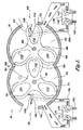
本発明の局面に従って構築されたデュアルローター内燃エンジン20(「エンジン20」)の1つの適切な実施形態は図1に示される。説明の容易さのために、図1は、断面で示されるエンジンの概略表示である。このエンジン20は、交差する領域を有する1対の平行な円筒形空洞24Aおよび24Bを規定するハウジング22を含む。このエンジン20はまた、共通の水平面と同一平面にある1対の平行なシャフト26Aおよび26Bを含む。各シャフト26Aおよび26Bは、空洞24Aおよび24B内でこれら平行なシャフト26Aおよび26Bの回転を許容するために、従来のベアリングを経由してハウジング22の長軸方向軸に沿ってジャーナル軸受けされる。シャフト26Aおよび26Bに、それとの回転のために強固に固定されて、それぞれ、第1のローター28Aおよび第2のローター28Bがある。示される実施形態では、これらローター28Aおよび28Bは、これらローター28Aおよび28Bのそれぞれの周囲の周りで等距離に間隔を置かれた3つのローブ32A、34A、36Aおよび32B、34B、36Bを有する。これらのローブ32A−32B、34A−34B、36A−36Bは、燃焼チャンバー172A−172B、174A−174B、176A−176Bをそれぞれ規定する。これらローブ32A、34A、36Aおよび32B、34B、36Bは、サイクロイドとして示される;しかし、卵形のようなその他の互いにかみ合う形状が用いられ得る。第1のローター28Aと第2のローター28Bは、シャフト26Aおよび26Bに、それらとの回転のために、ローター28Aの1つのローブが、ローター28Bの2つの隣接するローブの中間にかみ合うようにずらされた様式で固定して取り付けられ、その逆もまた真実である。
One suitable embodiment of a dual rotor internal combustion engine 20 (“
この第1のローターおよび第2のローターの、ほぼ摩擦のない、または接触のない内部かみ合わせを可能にするために、図3に最も良く示されるように、1対のギア30Aおよび30Bが、ハウジング22の端部壁40の1つの外側でシャフト26Aおよび26B上に固定して整列される。図3に描写されるエンジンは、説明の容易さのために単純化したエンジンの説明図であり;しかし、図3に示されるエンジンは、以下に詳細に記載されるように、その他の特徴および構成要素を含むことが認識される。これらギア30Aおよび30Bは、かみ合うようなサイズおよび形態であり、それによって、反対に回転するシャフト26Aおよび26Bの回転を同期するための連結をロックする力を形成する。これらギア30Aおよび30Bが、示されるように、ハウジング22の端部壁40の1つに隣接して位置決めされ得るか、または端部壁40の1つから間隔を置かれて離れた距離で取り付けられ、その他のエンジンアクセサリーまたは構成要素のためのスペースを提供するか、あるいはエンジン20のハウジング22への接近を確証することが認識される。
In order to allow internal engagement of the first and second rotors with substantially no friction or no contact, a pair of
これらシャフト26Aおよび26Bは、駆動シャフト52A、54Aおよび52B、54Bとして、それぞれ、両方の端部壁40の外側で延び得、そして、所望であれば、同期発電機、配電器、水ポンプ、流体ポンプのような補助機構を駆動するように適合され得る。この駆動シャフト52A、54Aおよび52B、54Bは、2〜3を指定すれば、発電機、船舶のデュアルプロペラ、陸上乗物の車輪を駆動するためにさらに適切である。さらに、この駆動シャフトは、特定の適用に基づく別個および異なる構成要素を駆動するために利用され得ることが認識される。例えば、エンジン20を採用する建設機械のような乗物は、この乗物の推進を提供するたに1つの駆動シャフトを利用し得、その一方、このような乗物の水力または空気力システムを駆動する動力取り出し装置(PTO)に連結するために別の駆動シャフトを利用する。従って、任意の数の駆動シャフトがその意図された適用に依存して利用され得る。
These
ここで、図2を参照して、ハウジング22がより詳細に記載される。ハウジング22は、2〜3を指定すれば、アルミニウム、鋳鉄または鋼のような、当該技術分野で公知の任意の適切なエンジンブロック材料から構築され得、そして鋳造、CNC機械加工などのような任意の従来の技法を用いて製作され得る。ハウジング22は、1対の平行な円筒形壁セクション38Aおよび38Bを含み、これらは、共通の垂直面Pで交差し、一般に空気プレナムアペックス42および排気プレナムアペックス44と称される長軸方向のエッジを形成する。交差する円筒形壁セクション38Aおよび38Bの内壁面48は、端部壁40の内面に沿って(図3を参照のこと)、1対の並んだ交差する実質的に円筒形の空洞24Aおよび24Bを規定する。上記シャフト26Aおよび26Bは、ボアを通る従来のベアリングによって個々にジャーナル受けされ(図2ではシャフトによって隠されている)、これらは、端部壁40を通って配置され(図3を参照のこと)、そして各空洞24Aおよび24Bの長軸方向軸と同軸に位置決めされる。アペックス42とアペックス44との間の距離は、角度50に対して規定され得、その頂点は、シャフト26Aおよび26Bのいずれかの中心点である。示される実施形態では、角度50は、約95゜である。ハウジング22は、垂直面Pの周りで実質的に対称であるような形態である。アペックス42の位置に、空洞24Aおよび24Bと流体連通して連結される圧力逃がしポート56が形成され、これらは、使用の間にエンジン中で増加した圧力を逃がすために、選択された空洞圧力(例えば、200psi)で開く従来の圧力逃がしバルブ(図示せず)によってバルブ調節され得る。
With reference now to FIG. 2, the
ハウジング22は、第1および第2のシリンダー壁セクション38Aおよび38B中にそれぞれ形成され、そして共通の垂直平面Pの周りに対称的に配置される、2つの第1の排気ポート60Aおよび60Bおよび2つの第2の排気ポート64Aおよび64Bをさらに含む。あるいは、これら第1および第2の排気ポートは、任意のエンジンブロック面中に形成され得、そして複数のポートから構成され得る。示される実施形態では、第1の排気ポート60Aおよび60Bの先頭エッジ70Aおよび70Bは、この実施形態では好ましくは約110゜である、ほぼ68で示される、排気プレナムアペックス44を超える回転の角度で開始する。第1の排気ポート60Aおよび60Bの尾部エッジ72Aおよび72Bは、先頭エッジ70Aおよび70Bを超えて好ましくは約10゜である回転80の角度で配置される。外壁セクションまたは間隔84Aおよび84Bが、第1の排気ポートおよび第2の排気ポートとの間にそれぞれ形成される。間隔84Aおよび84Bの長さは、第1の排気ポート尾部エッジ72Aおよび72Bと、第2の排気ポート先頭エッジ90Aおよび90Bとの間に形成される回転88の角度によって規定される。回転88の角度は、この実施形態では約10゜であり、そして以下に説明されるように、燃焼チャンバー開口部の回転角度に対応し得る。あるいは、回転88の角度は、所望であれば、10゜より大きいか、または小さくあり得る。第2の排気ポート64Aおよび64Bは、先頭エッジ90Aおよび90Bを超えて、ほぼ96で指定される回転の角度にある、尾部エッジ92Aおよび92Bで終わる。示される実施形態では、回転96の角度は、好ましくは約35゜である。従って、第2の排気ポート64Aおよび64Bの尾部エッジから空気プレナムアペックス42までの回転の残りの角度は、約100゜である。
The
本発明の局面によれば、第1の排気ポート60Aおよび60Bの先頭エッジ70Aおよび70Bの位置(アペックス44を超える回転68の角度として規定される)は、それぞれ、以下の式(1)によって決定され得る。
According to aspects of the invention, the positions of the
(1)L=(360/N)−X
ここで、L=ほぼ68で指定される、排気プレナムアペックス44からの回転の角度として決定される第1の排気ポート60Aおよび60Bの先頭の位置;
N=ローターあたりの燃焼チャンバーの数;および
X=各燃焼チャンバーの開口部を規定する度で表した回転の角度。
(1) L = (360 / N) −X
Here, the leading position of the
N = number of combustion chambers per rotor; and X = angle of rotation in degrees defining the opening of each combustion chamber.
従って、図1〜4の実施形態では、上記で説明されたように、Nは3に等しく、そしてXは10゜に等しく、L、または、回転の角度68は、110゜に等しい。
Thus, in the embodiment of FIGS. 1-4, as explained above, N is equal to 3 and X is equal to 10 °, and the L or
図1を戻って参照して、第1の排気ポート60A−60Bは、空洞24A−24B中の空気/燃料混合物の燃焼から生成された排気ガスを、従来のターボチャージャー110Aおよび110Bに輸送し得る。これらターボチャージャー110Aおよび110Bは、排気ガスを受容するために第1の排気ポート60Aおよび60Bと流体連通するタービン114Aおよび114Bを含む。排気ガスに駆動されるこれらタービン114Aおよび114Bは、次に、コンプレッサー118Aおよび118Bを駆動する。新鮮空気が、空気ライン122Aおよび122Bを経由し、ターボチャージャー110Aおよび110Bのコンプレッサー118Aおよび118Bを経由して採取され、そしてコンプレッサー118Aおよび118Bによって、通路126Aおよび126Bを経由して空気吸気ポート132Aおよび132Bに供給される。空気吸気ポート132Aおよび132Bは、ハウジング22中(端部壁40の1つ中)に配置され、そして空洞24A−24Bと流体連通して連結される。吸気ポート132Aおよび132Bは、それぞれ、アペックス44からほぼ130−160゜、そして示される実施形態では、好ましくは、145−150゜の回転で時計方向および反時計方向に配置される。吸気ポート132Aおよび132Bは、好ましくは、空気を、ターボチャージャー110Aおよび110Bから空洞24Aおよび24B中に矢印によって示されるように半径方向の外側に導入するような形態である。ハウジング22は、必要に応じて、吸気ポート132Aおよび132Bに隣接して位置決めされ、そして通路126Aおよび126Bと流体連通して連結される補助吸気ポート136Aおよび136Bをそれぞれ備えた形態であり得る。これら補助ポート136Aおよび136Bは、好ましくは、矢印によって示されるように、空気を、空洞24Aおよび24B中にローター回転の方向に導入するような形態であり、その利点は以下に詳細に説明される。
Referring back to FIG. 1, the
1つの実施形態(図示せず)では、その他のポートが、吸気ポート132Aおよび132Bならびに随意の吸気ポート136Aおよび136Bと対向する端部壁中に配置され得る。本発明者らは、上記のさらなるポートが導入された空気が上記チャンバーを吹き抜けることを可能にし、さらなる乱流、および付加された冷却能力および排気能力を生成すると考える。
In one embodiment (not shown), other ports may be located in the end wall opposite the
第1の排気ポート60Aおよび60Bが上記で説明され、そして本明細書中では、2つのターボチャージャー110Aおよび110Bに連結されて示されているけれども、当業者には、この第1の排気ポート60Aおよび60Bが単一のターボチャージャーに連結され得ることは明らかである。さらに、これらターボチャージャーは、多量の新鮮空気を、吸気ポート132Aおよび132Bならびに随意の136Aおよび136Bを経由して空洞中に導入するために示されているが、新鮮空気のこのような導入のためにその他のデバイスが用いられ得る。例えば、これら吸気ポートは、2〜3を指定すれば、すべてが当該技術分野で公知の、ブロワ、ファン、スーパーチャージャーに流体連通して連結され得る。
Although the
第2の排気ポート64Aおよび64Bは、燃焼ガスを、排気通路を通って大気に輸送する。当業者にとって、これら排気通路が、触媒コンバーター、マフラー、排気パイプ、またはそれらの任意の組み合わせなどに従来様式で連結され得ることは明らかである。あるいは、これら燃焼ガスのエネルギーを利用するために、これら第2の排気ポート64Aおよび64Bは、第1の排気ポート60Aおよび60Bに連結された第1のタービンと組み合わせて、改変された2つのタービンターボチャージャーのコンプレッサーを駆動するために第2のタービンを備えた形態のターボチャージャーに流体連通して連結され得る。
The
図2を参照して、スパークプラグ142Aおよび142Bのような2つの点火デバイスが、任意の従来様式で、アパーチャ144Aおよび144Bを通じてハウジング22にそれぞれ連結される。これらスパークプラグ142Aおよび142Bは、ローター回転を妨害しないように、アパーチャ144Aおよび144B内に凹部として取り付けられるか、または平らに取り付けられるかのいずれかである。スパークプラグアパーチャ144Aおよび144Bは、上記ハウジングの1つまたは両方の端部壁40中に形成され得る(図3を参照のこと)。スパークプラグ142Aおよび142Bは、このような目的のために当該分野で公知の任意の電源に連結されるよう適合され、燃料/空気混合物の燃焼を開始するために、電荷を空洞24Aおよび24Bに送達する。スパークプラグ142Aおよび142Bは間隔を置いて離れ、そして示されるように、シャフト26Aおよび26Bと同一平面上にあり得るか、またはそれに代わって、垂直平面Pと同じ面にあり得る。2つだけのスパークプラグアパーチャが示されるが、所望であれば、複数セットのスパークプラグアパーチャ、そしてそれ故、複数セットのスパークプラグが本発明とともに用いられ得、空気−燃料混合物のより完全な燃焼を提供することが認識される。さらに、スパークプラグアパーチャ、そしてそれ故、スパークプラグは、ローターが図1に示される位置にあるとき、燃焼チャンバー172Aと連通する任意の場所に位置決めされ得ることが認識される。
Referring to FIG. 2, two ignition devices, such as
1つまたは両方の端部壁40でハウジング22中にさらに形成されるのは(図3を参照のこと)、燃料の供給源に連結されるように適合され、空洞に燃料を供給するために空洞24Aおよび24Bと流体連通する燃料インジェクターポート154Aおよび154Bである。本発明の実施形態は、当該分野で公知のように、燃料インジェクターポート154Aおよび154Bを通じて上記空洞中に燃料を注入するために、スロットル本体または複数ポート(連続的)電子的燃料注入を利用し得る。しかし、燃料または燃料/空気混合物が、この電子的燃料注入とともに、または別個に、以下により詳細に説明されるように、従来のキャブレターまたはその他の機械的手段を用いてチャンバー中に注入され得ることが認識され得る。本発明で用いられる燃料は、任意の燃焼可能な流体、例えば、2〜3を指定すれば、ガソリン、アルコール、または水素であり得る。
Further formed in the
燃料インジェクターポート154Aおよび154Bは、ハウジング22の端部壁40(図8を参照のこと)中に、各インジェクターポート154Aおよび154Bを二分する線が、回転の角度160(図2を参照のこと)、好ましくは約30゜で、空気プレナムアペックス42からそれぞれ反時計方向および時計方向に位置決めされるように配置される。回転の角度160は30゜未満であり得、そして第2の排気ポートの排気サイクルを延長するためにアペックス42から約30゜以上(例えば45゜)〜約マイナス15゜の範囲であり得ることが認識される。燃料インジェクターポート154Aおよび154Bは、好ましくは、燃料をローター回転によって燃焼チャンバーから遠心分離されることから燃料(燃料/空気混合物)を維持するのを補助するため、そして燃料および空気の乱流および循環を生成し、それによって、燃焼チャンバー内に存在する注入された燃料と空気との間の混合プロセスを改善するために下部燃焼チャンバー壁の方向に導入するような形態である。燃料インジェクターポート154Aおよび154Bは、燃料が、インジェクターポート154Aおよび154Bがローターローブと整列するとき、それらの燃焼チャンバー中に注入され得るように、シャフト26Aおよび26Bの半径方向の外側に十分な距離間隔を置かれることが認識される。
The
ここで、図4を参照して、ここで、第1および第2のローターが詳細に説明される。この第1および第2のローターは、構成が実質的に同一であるので、第1のローター28Aのみが詳細に説明される。上記で簡単に論議されたように、この第1のローター28Aは、3つの半径方向に延びる、燃焼チャンバー172A、174A、および176Aをそれぞれ規定するサイクロイドローブ32A、34Aおよび36Aを備えて形成される。これらサイクロイドローブ32A、34Aおよび36Aは、隣接するローブを二分する長軸方向軸間に形成される168で指定される角度が120゜であるように、等距離に離れて開示されている。このローターの中心点とこれらローブの自由端部と間の長さは、これらローターが上記空洞内を自由に回転し得るが、これらローブとシリンダーセクションの内壁面との間の十分なシーリングを提供するように(例えば、数百分の1インチ、または数千分の1インチでさえある、ローブの自由端とシリンダー壁セクションの内面との間の許容誤差が企図される)、上記空洞の半径より僅かに小さい。
With reference now to FIG. 4, the first and second rotors will now be described in detail. Since the first and second rotors have substantially the same configuration, only the
燃焼チャンバー172A、174A、176Aは、ローブ32A、34A、および36Aの自由端でそれぞれ開いている。これらの開口は、ローター28Aの回転中心点(RCP)から延び、そして外側ローブ先導エッジ184Aおよび後続エッジ188Aをそれぞれ通って延びる仮想線によって形成される角度180(回転の角度とも称され、そして上記に記載の式(1)中「X」によって表される)によって規定される幅を有する。1つの実施形態では、この角度180は、好ましくは、約10゜であり、そして好ましくは、間隔84Aおよび84Bならびに第1の排気ポート60Aおよび60Bの幅に対応する。しかし、10゜よりも大きいか、または小さいその他の角度もまた、ならびに、これら間隔および/または第1の排気ポート60Aおよび60Bの幅とは異なる値を有する角度180が本発明の範囲内であることが企図される。
この燃焼チャンバーの特定の形状は本発明の一部ではなく、そしてそれ故、これ以上詳細には説明しない。しかし、ローターロープ側壁が、所望されないローター屈曲なくして燃焼された空気/燃料混合物の膨張を含むために十分剛直性のままである限り、任意の形状およびサイズが本発明とともに実施され得ることが認識される。1つの実施形態では、このローターローブは、図15に示されるように、必要に応じて、補強バー178で筋かい、または補強され得、ローブ側壁の屈曲に耐える。この補強バー178の直径は、燃焼ガスが燃焼チャンバーを出ることが可能なように、チャンバー開口部の縦の寸法より小さいことが認識される。この補強バー178は、ローブ側壁中に穴を穿孔すること、およびこれらの穴をバー178を受容するように口をあけること(すなわち、貫くこと)によって固定され得るが、溶接などのようなその他の技法が用いられ得る。さらに、上記燃焼チャンバーは、この燃焼チャンバーの開口部に隣接する突出部182を備えて形成され得る。これら突出部182は、形態がカップ様または中空であり、回転の間に燃焼チャンバー内の燃料の保持を支援するためにローブの先導エッジおよび追従エッジに沿って延びる。これら突出部182は、ローターの側面から燃焼チャンバー中に挿入可能なステンレス鋼ライナーとして構築され得る。
This particular shape of the combustion chamber is not part of the present invention and is therefore not described in further detail. However, it will be appreciated that any shape and size can be implemented with the present invention so long as the rotor rope sidewall remains rigid enough to contain the expansion of the air / fuel mixture burned without unwanted rotor bending. Is done. In one embodiment, the rotor lobe can be strung or reinforced with
本発明によるエンジン20の動作を、図5〜12を特に参照してここで説明する。以下の記載における説明の容易さおよび明瞭さのために、ターボチャージャーは示されていない;しかし、これらターボチャージャーは、本発明の1つの実施形態の一部であり得、そして図1に示されるような形態であり得ることが認識される。図5〜12において、ローター28Aおよび28Bは、8つの連続して生じる位置で説明される。これらの位置は、シャフト26Aおよび26Bの1つの完全な回転を通じて、1つのローターローブ32A(図5〜12全体で断面で示される)のサイクルを追従する。一般的に説明すれば、ローター28Aおよび28Bの各ローブ、そしてそれ故、各燃焼チャンバーは、6つのサイクルを通って作動し、これらは、以下により詳細に説明されるように、重複し得る。これらサイクルは:1)換気;2)燃料注入;3)置換え混合圧縮;4)燃焼;5)膨張;および6)排気である。
The operation of the
この詳細な説明において、エンジン20のこれらのサイクルは、図5で始まる。図5に最も良く示されるように、ローター28Aは、ローブ32Aの長軸方向軸がハウジング22の第2の排気ポート64Aの二分軸とほぼ同一平面にあり、ローブ34Aの追従エッジ188Aがアペックス42の近傍にあり、そしてローブ34Bがローブ34Aと36Aとの間で互いにかみ合うように位置決めされる。この位置では、先の排気サイクルからの排気ガスによって駆動される、これらターボチャージャー(図1を参照のこと)は、以下により詳細に説明されるように、空洞24A中、そしてより詳細には、吸気ポート132A、そして随意の吸気ポート136Aを通って、燃焼チャンバー172A中に新鮮空気を注入する。あるいは、従来のスーパーチャージャー、ブロワ、ファン、または空気の加圧リザーバーのようなその他の手段による空気注入が、これらターボチャージャーの代わりに、または組み合わせて利用され得る。ポート132Aの好ましい形態に起因して、空気は、第2の排気ポート64Aに向かって半径方向の外側に導入される。これは、導入された空気が、燃焼チャンバー172A中になお存在する排気ガス(点で示される)を第2の排気ポート64A中に排出することを可能にし、その一方、チャンバー172Aを新鮮空気で充填する。新鮮空気がチャンバー172Aを排出するのみならず、ハウジング22およびローターを冷却するようさらに機能する。従って、吸気ポートに経路をとった新鮮空気は、まず、空洞中への導入の前に従来の中間冷却器に導入され、エンジンをさらに冷却し得る。
In this detailed description, these cycles of
これは、換気サイクルを終了させ、ここで、新鮮空気が燃焼チャンバー172A中に注入され、そして燃焼チャンバーからの残存燃焼ガスが除去される。この場合、ターボチャージャーは、空気ポンプとして作用し、大容量の空気を燃焼チャンバー172A中に、そしてそれを通じてポンプ輸送し、新鮮空気をチャンバーに供給しながら、チャンバーから燃焼ガスを排出する。従って、これらターボチャージャーは、一般に、ターボ−換気装置と称され得る。換気サイクルは、吸気ポート132Aおよび/または136Aがチャンバー172Aと流体連通しているとき開始し、そして吸気ポート132Aおよび/または136Aがチャンバー172Aと流体的に連通することを止めるときほぼ終了することが認識される。以下に詳細に記載されるように、先のローブの排気サイクルが、この換気サイクルと同時に生じ得ることもまた認識される。
This ends the ventilation cycle, where fresh air is injected into the
図5から、ローター28Aおよび28Bは、別の燃焼チャンバーの燃焼ガスの膨張力に起因して図6に示される位置に矢印の方向に回転する。図6は、燃料インジェクターポート154Aがチャンバー172Aと流体連通し、そしてローブ34Aの先導エッジ184Aがアペックス44に緊密に近接するような位置にあるローター28Aを示す。この位置では、燃料インジェクターポート154Aは、燃料を、新たに空気が充填されたチャンバー172A中に注入し、これは、瞬時に蒸発し、空気/燃料混合物を形成する。これは、一般に、燃料注入サイクルと称される。本発明の実施形態は、当該技術分野で公知のように、燃料を燃焼チャンバーに注入するために電子燃料注入を利用し得る。しかし、燃料または燃料/空気混合物は、以下により詳細に説明されるように、この電子燃料注入とともに、または別個に、従来のキャブレターまたはその他の機械的手段を用いてチャンバー中に注入され得ることが認識される。
From FIG. 5, the
エンジンの動作間に,ローター28Aおよび28Bは、図6に示される位置から、図7に示される位置まで回転し続ける。ローターが図6から図7に回転するとき、チャンバー200中にある空気(これはまた、先のサイクルからの所定量の燃焼ガスを含み得る)は、チャンバー172Aに向かって反時計方向に回転するローブ32Bの外壁のポンプ輸送作用によってチャンバー172A中に押され得る。このポンプ輸送作用は、空気/燃料混合物を圧縮し得、そして/またはチャンバー172A中に存在する空気の容量を増加することが認識される。これは、一般に、変位配合圧縮サイクルと称される。さらに、この変位配合圧縮サイクルの間に、アペックス42に隣接し、そしてポート56と流体連通するローブ32Bおよび32Aを互いにかみ合うことにより形成されるチャンバー内の圧力が、ポート56を通じて排出するために十分増加し得ることが認識される。ポートが圧力逃がしバルブで調整される実施形態では、生成されたチャンバー内の圧力増加は、この圧力が予め選択された閾値(例えば、200psi)を超える場合に排出される。
During engine operation, the
図7は、ローブ32Aが、このローブ32Aの長軸方向軸がシャフト26Aおよび26Bを相互連結する水平線と実質的に同軸にあり、燃焼チャンバー172Aがローブ32Bと36Bとの間でローター28Bの外面と並列されたローブ32Aの自由端によって実質的に閉鎖され、スパークプラグがスパークプラグアパーチャ144Aおよび144Bを通じてチャンバー172Aと連通し、そしてチャンバー172Aが次の燃焼のための空気/燃料混合物を含むように配向される位置にある、ローター28Aおよび28Bを示す。この時点では、スパークプラグは、配電器または従来様式のその他の公知のデバイスから電荷を受け、そして発火し、それによって、燃焼チャンバー172A内に含まれる空気/燃料混合物を点火する。燃焼ガス(図面全体で点として示される)は、一般に、軸方向力と称され、二重ヘッド矢印F1によって指定される膨張力を生成する。燃焼ガスが、軸方向力F1、そして引き続くガスの膨張から対向するローター28Bの凹状部分に圧力を付与し続けるとき、ローター28Aは反時計方向に回転し、これは、次に、図8に示される位置にギアを同期することに起因してローター28Aを回転する。スパークプラグは、ローブ32Aの長軸方向軸が、シャフト26Aおよび26Bが燃焼に際し膨張力を支援して含み得るようにこれらシャフトと同軸にある瞬間に発火するよう制御され得るが、このスパークプラグは、共通のシャフト軸の前または後に数度の回転(例えば、;約10゜まで)で発火するよう制御され得ることが認識され得る。
FIG. 7 shows that
ローブ32Aの先導エッジ184Aは、ローター28Aおよび28Bが図7に示される位置から図8に示される位置に回転するとき、対向するローター28Bの凹状部分から分離され、燃焼ガスは燃焼チャンバー172Aから逃れ、そして燃焼チャンバー172Aによって生成されたチャンバー204、ローブ32Aおよび34Aの外壁と、ローブ34Aの追従エッジ188Aで始まり、そしてアペックス44で終わる、シリンダーセクション38Aの内壁面48との間で区切られたスペース、ならびに(ローブ32Aに面する)ローブ32Bおよび36Bの外壁と、ローブ36Bの追従エッジ188Bで始まり、そしてアペックス44で終わる円筒形セクション38Bとの間で区切られたスペース中に膨張する。燃焼ガスが燃焼チャンバー172Aから新たに形成されたチャンバー204中に逃れるとき、燃焼ガスは容積が膨張し、これは、次いで、その時点で別のサイクルからのチャンバー中に存在する(そして既に高められた圧力にある)燃焼ガスを混合して圧縮、それによって、図8に示される第2の力F2を生成する。従って、チャンバー204を占領するときガスの第2の膨張、および現存するガスの同時の混合圧縮は、ローターローブ36Bの側面に対して力F2を付与し、これは、次いで、ローター28Bを反時計方向に回転させる。これは、一般に、膨張サイクルと称され、それによって、上記燃焼サイクルからのエネルギーは、ローター28Aおよび28Bを回転するためにさらに利用される。続いて説明されるように、この膨張サイクルは、ローターが回転し続けるとき、動作し続け得る。この膨張サイクルの長さは、燃焼サイクルに存在する空気/燃料混合物の量のようないくつかの変数に依存し得る。
The
ローター28Aおよび28Bは、膨張サイクルに起因して図9の位置まで回転し続ける。ローブ32Aの先導エッジ184Aが、図9に最も良く示されるように排気プレナムアペックス44に緊密に近接するとき、ロープ34Aの追従エッジ188Aは、第1の排気ポート先頭エッジ70Aに緊密に近接し、そしてチャンバー204(図8)は、分割されてチャンバー206および208を形成する。チャンバー206は、ローター28Aの隣接ローブ32Aおよび34Aの外面、およびアペックス44と第1の排気ポート60Aの先頭エッジ70Aとの間のシリンダー壁の隣接する内面48によって区切られる。チャンバー208は、ローター28Bの燃焼チャンバー172Aおよび隣接するローブ32Aと36B、ならびにローブ36Bの追従エッジ188Bからアペックス44まで延びるシリンダー壁セクション38Bの隣接する内面48によって区切られる。この時点で、チャンバー208内に含まれる燃焼ガスは、高圧下にあり、そして混合圧縮された燃焼ガスからの残りの力F2は、ローター28Bのローブ36Bに対して衝撃を与え、これは、次に、ローター28Bを反時計方向に回転する。
ローターが図9に示される位置から図10に示される位置に回転するとき、ローブ34Aの追従エッジ188Aは、第1の排気ポート60Aの先頭エッジ70Aを尾部エッジ72Aまで通過し、そしてローブ32Aの追従エッジ188Aはアペックス44に隣接し、以下を生じさせる。第1に、これは、チャンバー206と第1の排気ポート60Aとの間の流体連通を確立し、これは、次に、第1の排気ポート60Aを横切るチャンバー206の排気サイクルの第1の排気部分を開始する。排気ポート60Aは、燃焼ガスのチャンバー206より低い圧力にあるので、燃焼ガスは、チャンバー206を出て、第1の排気ポート60Aに入る。燃焼ガスは、ポート60Aを通って排気され、そして、上記に記載のように、ターボチャージャーのタービンに経路をとるか、またはそれに代わって大気中に経路をとる。
When the rotor rotates from the position shown in FIG. 9 to the position shown in FIG. 10, the trailing
第2に、その中に排気ガスを含むチャンバー172Aは、チャンバー208から分離される。最後に、チャンバー208中の混合圧縮ガスは、ローブ36Bの外壁に対して力F2を奏し続け得、そしてそれ故、上記の膨張サイクルを延長する。今や、チャンバー208の容量は、隣接ローブ32Bおよび36Bの外面、ローブ36Bの追従エッジ188Bとアペックス44との間のシリンダー壁の隣接する内面48、およびローブ32Aの追従エッジ188Aから、ローブ32Aとローブ32Bとの間の界面までのローブ32Aの隣接する外壁部分によって区切られ、ローター28Bが回転するとき、拡大し続け、それ故、その中の圧力を減少することが認識される。
Second,
図10に示される位置から、ローターは、他のローブの燃焼チャンバーにおける次の燃焼サイクルによって一部起因し、図11に示される位置まで回転する。図11では、ローブ34Aの追従エッジ188Aは、第2の排気ポート64Aの尾部エッジ92Aを超える。ローブ34Aの追従エッジ188Aが、第1の排気ポート60Aの尾部エッジ72Aにある図10中のその位置から、第2の排気ポート64Aの尾部エッジ92Aを超える位置まで回転するとき、チャンバー206は、第2の排気ポート64Aとの流体連通を確立し、これは、次に、第2の排気ポート64Aを横切るチャンバー206の排気サイクルの第2の排気部分を開始する。外部ポート64Aは、燃焼ガスのチャンバー206より低い圧力であるので、燃焼ガスは、第2の排気ポート64A中へとチャンバー206を出る。燃焼ガスは、このポート64Aを通って排気され、そして大気に、またはそれ代わり、ターボチャージャーのタービンに経路をとる。従って、この時点で、チャンバー206中に先に含まれた排気ガスは、第1および第2のポート60Aおよび64Aを通じてそれぞれ廃棄されている。
From the position shown in FIG. 10, the rotor rotates to the position shown in FIG. 11 due in part to the next combustion cycle in the combustion chamber of the other lobe. In FIG. 11, the
エンジンの動作は、ローター28Aおよび28Bを、図12に示される位置まで回転し続ける。図12に最も良く示されるように、ローブ36Bの追従エッジ188Bは、第2の排気ポート64Bの先頭エッジ90Bを超えて回転し、そしてそれ故、チャンバー208と、第1の排気ポート60Bおよび第2の排気ポート64Bとの間の流体連通を確立する。これは、第1および第2の排気ポート60Bおよび64Bを横切るチャンバー208の排気サイクルの第1および第2の排気部分を開始する。排気ポート60Bおよび64Bは、燃焼ガスのチャンバー208より低い圧力にあるので、燃焼ガスは、チャンバー208を出て、第1および第2の排気ポート60Bおよび64B中に入る。燃焼ガスは、ポート60Bおよび64Bを通って排気され、そして、上記に記載のように、大気またはターボチャージャーのタービンのいずれかに経路をとる。チャンバー208からの燃焼ガスの排出と同時に、チャンバー206の燃焼ガスは、第1および第2の排気ポート60Aおよび64Aを横切る排気サイクルのそれらの第1および第2の部分を継続する。排気サイクルが生じるとき、新鮮空気は、吸気ポート132Aおよび随意の吸気ポート136Aを通ってハウジング中に注入される。上記で記載されたように、随意の吸気ポートは、好ましくは、ハウジング中でローター回転の方向に導入されるような形態である。このローター回転の方向に導入された空気は、ローターローブ34Aの外壁に対して、F3でほぼ指定される力を与える。従って、注入された空気は、燃焼チャンバーの排気サイクルを支援しながら、ローターの回転を支援する。
Engine operation continues to rotate
図12に示されるローター位置から、図5の開始ローター位置まで、チャンバー206および208は、第1および第2排気ポート60A、64Aおよび60B、64Bをそれぞれ通じて燃焼ガスを排出し続ける。さらに、ローブ32Aの燃焼チャンバー172Aが、第2の排気ポート64Aまで第1の排気ポート60Aを通過するとき、それらの間に流体連通が確立され、そしてそれ故、燃焼チャンバー172Aは、その排気サイクルの第1および第2の部分を開始する。従って、この排気サイクルは、チャンバー206および208が第1の排気ポート60Aおよび60Bとの流体連通を確立するとき開始し、そしてローブ32Aの追従エッジ188Aが第2の排気ポート64Aの尾部エッジ92Aを通過し、そしてローブ36Bの追従エッジ188Bが第2の排気ポート64Bの尾部エッジ92Bを通過するときに終わる。
From the rotor position shown in FIG. 12 to the starting rotor position of FIG. 5, chambers 206 and 208 continue to discharge combustion gases through first and
エンジン20の動作においてローブ32Aのサイクルのみを詳細に説明したが、その他のローブがそれらの個々のサイクルを通じてローブ32Aと同時に作動していたことが認識される。
Although only the cycle of
本発明の別の実施形態では、エンジン20は、図13に最も良く示されるように、必要に応じて、供給導管から燃焼チャンバーまで空気または燃焼可能なガスを注入するために、インジェクターポート154Aおよび154B、ならびにスパークプラグアパーチャ144Aおよび144Bのそれぞれ中間に位置する吸気ポート240Aおよび240Bを含み得る。注入された空気は、空気/燃料混合物の圧縮比を増加するよう、そして/または燃焼チャンバー内に含まれる空気の総容積を増加するように操作され得、それによってエンジン出力を増加する。供給導管から吸気ポート240Aおよび240Bまでの空気の供給は、ソレノイドバルブのようなバルブ機構と連絡するエンジン制御ユニット(ECU)のような従来のコントローラーによって電子的に制御され得る。吸気ポート240Aおよび240Bに供給される空気の供給源は、駆動シャフトの1つに機械的に連結された、従来のエアポンプ、ブロワまたはコンプレッサーの適正な使用によって注入され得る。
In another embodiment of the present invention, the
作動において、ローター28Aおよび28Bの各燃焼チャンバーが回転して、個々の吸気ポート240Aまたは240Bと整列するとき、空気が、ECUからの制御信号を受容するバルブ機構(図示せず)の作動によって個々の燃焼チャンバー中に注入される。
In operation, when each combustion chamber of
あるいは、まさに説明された随意の吸気ポートから燃焼チャンバー中に注入された空気の供給源は、ここでより詳細に説明されるように、機械的に制御され得る。ここで図14を参照して、このエンジンは、図13に示される実施形態から半径方向の内側に位置決めされる吸気ポート240Aおよび240Bを含む。詳細には、これら吸気ポート240Aおよび240Bは、端部壁40の1つに配置され(図3)、そしてシャフト26Aおよび26Bと同軸に半径Rの仮想の円(IC)上で中心にある。仮想の円ICの半径Rは、ポート240Aおよび240Bが、燃焼チャンバーの内方端部とシャフトの外側面と間に横たわるように選択される。吸気ポート240Aおよび240Bの配置と組み合わせて、ローター28Aおよび28Bは、これらのローター28Aおよび28Bの中央ハブセクション中に形成され、そして各燃焼チャンバーと関連する溝262A−262B、264A−264Bおよび266A−266Bをさらに含む。各溝は、ハブセクション全体を通じて縦に延び、そしてその個々の燃焼チャンバーと流体により連通するような形態であり、かつ整列される。
Alternatively, the source of air injected into the combustion chamber from the optional intake port just described can be mechanically controlled, as described in more detail herein. Referring now to FIG. 14, the engine includes
作動において、ローター28Aおよび28Bの各溝が回転して、個々の吸気ポート240Aまたは240Bと整列されるとき、空気が、その関連する溝を通じて個々の燃焼チャンバー中に自動的に注入される。個々の燃焼チャンバーと関連する溝が、個々の吸気ポートを超えて回転するとき、空気の供給は、個々のローターの中央ハブ部分の端面によって切断される。注入される空気の量は、供給導管中のレール圧力、ならびに吸気ポートおよび/または溝のサイズおよび形状の任意の組み合わせによって計測され得ることが認識される。さらに、この空気供給はまた、所望であれば、バルブ制御され得る。
In operation, when each groove of the
この実施例では、空気がエンジン出力を潜在的に増加すると説明してきたが、空気は、このような結果を潜在的に達成するために利用可能な唯一の構成要素ではない。例えば、水、または酸化窒素もしくはその他の揮発性ガス状または液体成分が、エンジン仕事出力を潜在的に増加するために吸気ポート240Aおよび240B中に注入され得る。
In this example, air has been described as potentially increasing engine power, but air is not the only component available to potentially achieve such results. For example, water, or nitric oxide or other volatile gaseous or liquid components can be injected into
本発明の別の実施形態によれば、エンジン20は、燃焼チャンバー中に燃料および/または空気/燃料混合物を注入するためにまさに説明した、空気の機械的に制御された供給に類似の機械的技法を用い得る。この目的のために、エンジン20は、吸気ポート154Aおよび154Bから半径方向の内方に位置決めされ、そして半径Rの仮想円IC上でほぼ中心にある吸気ポート280Aおよび280Bをさらに含み得る。吸気ポート280Aおよび280Bは、燃料または空気/燃料混合物の供給源に連結されるよう適合される。この実施形態では、吸気ポート280Aおよび280Bおよび吸気ポート154Aおよび154Bは、所望であれば、省略され得ることに注目すべきである。吸気ポート240Aおよび240Bが、図14に示されるようなエンジンの実施形態によって利用される場合、これらのポート280Aおよび280Bは、ポート240Aおよび240Bから、回転の度で、所定距離間隔を置かれることが認識される。あるいは、本発明の別の実施形態によれば、その他のポートが省略されて、1つのセットのポート、ポート240Aおよび240Bまたはポート280Aおよび280Bのいずれかが、燃料/空気混合物、および空気または上記に記載のその他のエンジン出力増加成分の両方を注入するために用いられ得る。この特定の実施形態では、これらポートは、燃料および空気(または上記に記載のその他のエンジン出力増加成分)の別個の供給源に連結され得、そしてバルブ機構によって制御され得る。このような配列は、当該分野で周知の構成要素とともに当業者によって構築され得る。
According to another embodiment of the invention, the
作動において、ローター28Aおよび28Bの溝が回転して、燃焼インジェクターポート280Aおよび280Bと整列するとき、燃料または空気/燃料混合物が個々の燃焼チャンバー中に自動的に注入され、そして溝が回転して個々の燃料インジェクターポートを通過するとき、燃料または空気/燃料混合物の供給は、個々のローターの端面によって切断される。エンジンが遮断されるときのような場合には、制御バルブが用いられ得ることが認識される。本発明の別の実施形態によれば、インジェクターポート280A−280Bは、図14に示されるようなインジェクターポート154Aおよび154Bと組み合わせて用いられ得、変化するエンジン作動条件の間に燃焼チャンバーに燃料を供給する際に柔軟性を提供する。例えば、第1のセットの燃料インジェクターポート280Aおよび280Bが燃料の供給源
連結され得、そして通常の作動条件の間に作動する。第2のセットの燃料吸気ポート154Aおよび154Bが、従来の電子燃料インジェクターと連結され得、そしてピークエンジン条件の間に作動し得る。エンジンが、通常の作動条件下で作動しているとき、吸気ポート280Aおよび280Bを用いて、燃料を燃焼チャンバー中に注入する。より大きいエンジン出力の要求が必要であるとき、これらの燃料吸気ポート154Aおよび154Bは、吸気ポート280Aおよび280Bと組み合わせて用いられ得、燃焼チャンバーにより多くの燃料を供給する。
In operation, when the
上記に記載され、そして図1〜14に示されるエンジン20の実施形態では、ローターには、各々が燃焼チャンバーを規定する3つのローブが含められる。しかし、本発明のその他の実施形態は、任意の数の同様の番号付けされたローブを有するローターを利用し得る。図16〜18をここで参照して、デュアルローターエンジン320の別の実施形態が、本発明の局面に従って示される。図16〜18中のエンジン320は、ここで説明される差異を除いて、図1に示されるエンジン20と構築および操作において実質的に同一である。説明を確実にする際の明瞭さのために、同様または類似の要素は、接頭語300または400のいずれかで始まる同じ参照番号を有する。例えば、この実施形態におけるハウジングは、ここで参照番号322である。
In the embodiment of
図16および17に最も良く示されるように、ローター328Aおよび328Bは、ローター328Aおび328Bの周囲の周りで等距離だけ間隔を置かれた、それぞれ、4つのサイクロイドローブ332A、334A、336A、337A、および332B、334B、336B、337Bを有する。サイクロイドローブ332A、334A、336A、および337Aは、隣接するローブを二分する長軸方向軸間で形成される468で指定される角度(図18を参照のこと)が、90゜であるように等距離で配置される。ローター328Aの各ローブ332A、334A、336A、および337Aは、燃焼チャンバー472A、474A、および476A、および477Aとともにそれぞれ形成され、その一方、ローター328Bの各ローブ332B、334B、336B、377Bは、燃焼チャンバー472B、474B、および476B、および477Bとともにそれぞれ形成される。
As best shown in FIGS. 16 and 17,
ここで図17を参照して、ハウジング322は、アペックス342とアペックス344との間の角度350が約88゜であるような形態である。このハウジング322はまた、第1および第2のシリンダー壁セクション338Aおよび338B中にそれぞれ形成され、そして共通垂直面Pの周りで対称的に配置される、2つの第1の排気ポート360Aおよび360Bおよび2つの第2の排気ポート364Aおよび364Bを含む。第1の排気ポート360Aおよび360Bの先頭エッジ370Aおよび370Bは、アペックス44を超えて368で指定される回転の角度で始まる。第1の排気ポートの先頭エッジ370Aおよび370Bの回転の角度368は、上記の式(1)によって決定され得る。従って、好ましくは10゜であるXで、回転の角度368は80゜に等しい((360゜/4)−10゜=80゜)。
Referring now to FIG. 17, the
この第1の排気ポート360Aおよび360Bの尾部エッジ372Aおよび372Bは、先頭エッジ370A−370Bを超えて、それぞれ、好ましくは約10゜である回転の角度380にある。外壁セクションまたは間隔384は、第1の吸気ポートと第2の吸気ポートとの間にそれぞれ配置される。この間隔384の長さは、第1の排気ポート尾部エッジ372Aおよび372Bと、第2の排気ポート先頭エッジ390Aおよび390Bとの間にそれぞれ形成される回転の角度388によって規定される。回転の角度388は、この実施形態では約10゜であるが、所望であれば、10゜より大きく、または10゜より小さくあり得る。第2の排気ポート364Aおよび364Bは、尾部エッジ392Aおよび392Bで終わり、これらは、先頭エッジ390Aおよび390Bを超えて、396で指定される回転の角度にある。示される実施形態では、この角度396は好ましくは35゜であり;しかし、約70゜までの角度が用いられ得る。
The tail edges 372A and 372B of the
本発明の代表的な実施形態が示され、そして説明されているが、請求項に記載のように、本発明の思想および範囲から逸脱することなくその中で種々の変更がなされ得ることが認識される。例えば、燃料インジェクターは、所望であれば、その他の領域に位置決めされ得る。さらに、いくつかの実施形態では、第1および第2のポートがサイズが異なり得る1つの大きなポートになるように上記の間隔は省略され得る。 While representative embodiments of the present invention have been shown and described, it will be appreciated that various changes can be made therein without departing from the spirit and scope of the invention as set forth in the claims. Is done. For example, the fuel injector can be positioned in other areas if desired. Further, in some embodiments, the above spacing may be omitted so that the first and second ports are one large port that may be different in size.
Claims (37)
1対の端部壁、および第1の相互接続シリンダー空洞および第2の相互接続シリンダー空洞を規定する内壁面を有する1対の交差する平行シリンダー壁を含むハウジングであって、該交差するシリンダー壁が、間隔を置いて離れた平行の第1のエッジおよび第2のエッジを形成するハウジング;
該空洞中で同軸に延び、そして該端部壁で回転のために支持される、第1のシャフトおよび第2のシャフト;および
該個々の空洞における回転のために該第1のシャフトおよび第2のシャフトに取り付けられる第1のローターおよび第2のローターであって、各々が外側端部をもつ半径方向に延びる複数のローブを有し、各ローブが該ローブの外側端部で開く燃焼チャンバーを規定する第1のローターおよび第2のローター、を備える、エンジン。 The engine:
A housing comprising a pair of intersecting parallel cylinder walls having a pair of end walls and an inner wall defining a first interconnect cylinder cavity and a second interconnect cylinder cavity, the intersecting cylinder walls Forming a spaced apart parallel first edge and second edge;
A first shaft and a second shaft extending coaxially in the cavity and supported for rotation at the end wall; and the first shaft and second for rotation in the individual cavity A first rotor and a second rotor attached to the shaft of the combustion chamber, each having a plurality of radially extending lobes with outer ends, each lobe opening at the outer end of the lobes. An engine comprising a first rotor and a second rotor that define the engine.
1対の並んだ交差する実質的に円筒形の空洞を備えて形成されるハウジング;
該空洞中に取り付けられる1対の反対に回転するパワーローターであって、各々が開放端部の燃焼チャンバーを規定する互いにかみ合うローブを含む1対のパワーローター;
該1対の空洞と流体連通して該ハウジング中に形成された少なくとも2つの排気ポート;
該空洞と連通する点火デバイス;
該ハウジング中に配置され、そして該空洞と流体連通して連結される第1の燃焼吸気ポートおよび該第2の燃料吸気ポート;および
該ハウジング中に配置され、そして該空洞と流体連通して連結される、第1の空気吸気ポートおよび第2の空気吸気ポート、を備える、エンジン。 The engine:
A housing formed with a pair of side-by-side intersecting substantially cylindrical cavities;
A pair of counter-rotating power rotors mounted in the cavity, each including a pair of interlocking lobes defining an open end combustion chamber;
At least two exhaust ports formed in the housing in fluid communication with the pair of cavities;
An ignition device in communication with the cavity;
A first combustion intake port and the second fuel intake port disposed in the housing and coupled in fluid communication with the cavity; and disposed in the housing and coupled in fluid communication with the cavity A first air intake port and a second air intake port.
平行な円筒形形状の交差する空洞を規定するハウジング;
該空洞内に回転可能に取り付けられた1対の平行なシャフトであって、該ハウジングの外側に延び、少なくとも1つの駆動シャフトを形成する1対の平行なシャフト;および
該ハウジング内に回転可能に取り付けられた第1および第2の互いにかみ合うローターであって、ローターの各々が、シャフトの1つにそれとの回転のために連結される中央ハブ部分、および多数の開放端部の燃焼チャンバーを規定する半径方向の外側に延びるローブを備えた形態のローター、を備える、エンジン。 The engine:
A housing defining intersecting cavities of parallel cylindrical shape;
A pair of parallel shafts rotatably mounted within the cavity, the pair of parallel shafts extending outside the housing and forming at least one drive shaft; and rotatably within the housing Mounted first and second interdigitating rotors, each defining a central hub portion coupled to one of the shafts for rotation therewith, and a number of open end combustion chambers A rotor in the form of a radially outwardly extending lobe.
1対の並んだ交差する実質的に円筒形の空洞を備えて形成されるハウジング;
該空洞中に取り付けられる1対の反対に回転するパワーローターであって、各々が開放端部の燃焼チャンバーを規定する互いにかみ合うローブを含む1対のパワーローター;
該ハウジング中に形成され、そして各燃焼チャンバーに空気を注入するために、該空洞と空気の供給源と流体連通して連結される第1の吸気ポートおよび第2の吸気ポート;
該ハウジング中に形成され、そして各空気が充填された燃焼チャンバーに燃料を注入し空気/燃料混合物を形成するために、該空洞と燃料の供給源と流体連通して連結される第3の吸気ポートおよび第4の吸気ポート;
該ハウジングに連結され、そして該ローターローブが完全に互いにかみ合うとき個々の燃焼チャンバーと実質的に整列される点火デバイスであって、該整列された燃焼チャンバー内で空気/燃料混合物を点火するように適合され、そしてそれによって、該空気/燃料混合物の点火から生じる燃焼ガスが該ローブに対して作用し、該ローターを回転する点火デバイス;および
該ハウジング中に形成され、該1対の空洞と流体連通する少なくとも2つの排気ポートを備え、ここで、該燃焼ガスが、さらなるローター回転によって該排気ポートを通って実質的に逃れる、エンジン。 The engine:
A housing formed with a pair of side-by-side intersecting substantially cylindrical cavities;
A pair of counter-rotating power rotors mounted in the cavity, each including a pair of interlocking lobes defining an open end combustion chamber;
A first intake port and a second intake port formed in the housing and coupled in fluid communication with the cavity and a source of air for injecting air into each combustion chamber;
A third intake air formed in the housing and connected in fluid communication with the cavity and a fuel source to inject fuel into each air filled combustion chamber to form an air / fuel mixture. A port and a fourth intake port;
An ignition device coupled to the housing and substantially aligned with the individual combustion chambers when the rotor lobes are fully engaged with each other so as to ignite an air / fuel mixture within the aligned combustion chambers An ignition device that is adapted and thereby causes combustion gases resulting from ignition of the air / fuel mixture to act on the lobe and rotate the rotor; and formed in the housing, the pair of cavities and fluids An engine comprising at least two exhaust ports in communication, wherein the combustion gases substantially escape through the exhaust ports by further rotor rotation.
Applications Claiming Priority (2)
| Application Number | Priority Date | Filing Date | Title |
|---|---|---|---|
| US10/723,845 US6988482B2 (en) | 2003-11-26 | 2003-11-26 | Dual rotor internal combustion engine |
| PCT/US2004/039378 WO2005054642A1 (en) | 2003-11-26 | 2004-11-22 | Dual rotor internal combustion engine |
Publications (2)
| Publication Number | Publication Date |
|---|---|
| JP2007512476A true JP2007512476A (en) | 2007-05-17 |
| JP2007512476A5 JP2007512476A5 (en) | 2007-12-27 |
Family
ID=34592403
Family Applications (1)
| Application Number | Title | Priority Date | Filing Date |
|---|---|---|---|
| JP2006541667A Pending JP2007512476A (en) | 2003-11-26 | 2004-11-22 | Dual rotor internal combustion engine |
Country Status (7)
| Country | Link |
|---|---|
| US (1) | US6988482B2 (en) |
| EP (1) | EP1704311A4 (en) |
| JP (1) | JP2007512476A (en) |
| CN (1) | CN1882768A (en) |
| CA (1) | CA2545988A1 (en) |
| CR (1) | CR8483A (en) |
| WO (1) | WO2005054642A1 (en) |
Cited By (1)
| Publication number | Priority date | Publication date | Assignee | Title |
|---|---|---|---|---|
| WO2010101148A1 (en) * | 2009-03-04 | 2010-09-10 | Kanai Katuo | Rotary engine |
Families Citing this family (18)
| Publication number | Priority date | Publication date | Assignee | Title |
|---|---|---|---|---|
| AU2002952005A0 (en) * | 2002-10-11 | 2002-10-31 | Hudson, Barry | A rotary engine |
| US7328672B2 (en) * | 2005-04-29 | 2008-02-12 | Tendik Development, Llc | Radial impulse engine, pump, and compressor systems, and associated methods of operation |
| EP2052131A1 (en) * | 2006-08-17 | 2009-04-29 | Yves Sauget | A rotary machine having frusto-conical elements |
| US8117824B1 (en) * | 2009-02-04 | 2012-02-21 | The United States of America as represented by the Secterary of the Navy | Pollution free engine using hydrogen as a fuel |
| US20110036653A1 (en) * | 2009-08-11 | 2011-02-17 | Clyde Platt | Internal combustion rotary engine with intermeshing rotors |
| CN102278197A (en) * | 2010-06-10 | 2011-12-14 | 杨兴隆 | Double combustion disc type energy saving engine |
| US8613269B2 (en) * | 2010-09-11 | 2013-12-24 | Pavel Shehter | Internal combustion engine with direct air injection |
| US9435203B2 (en) | 2010-10-22 | 2016-09-06 | Peter South | Rotary positive displacement machine |
| WO2012057838A2 (en) * | 2010-10-27 | 2012-05-03 | Jesus Vazquez | Rotary valve continuous flow expansible chamber dynamic and positive displacement rotary devices |
| CN103790637B (en) * | 2012-10-31 | 2016-06-01 | 北京星旋世纪科技有限公司 | The fluid machinery of two-wheel star rotary, engine, fluid motor, compressor and pump |
| CN103883391B (en) * | 2014-01-26 | 2016-04-27 | 王文阁 | A kind of reciprocating engine and consisting of engine device |
| CN103790699A (en) * | 2014-03-05 | 2014-05-14 | 江悦林 | Rotary engine |
| WO2015163926A1 (en) * | 2014-04-25 | 2015-10-29 | Takayuki Arima | Rotary synchronized combustion engine |
| DK3165764T3 (en) * | 2015-11-06 | 2021-06-21 | Sb Patent Holding Aps | Yaw brake for a wind turbine |
| US10514036B2 (en) * | 2017-07-25 | 2019-12-24 | GM Global Technology Operations LLC | Rotor for a positive displacement compressor |
| FR3071545B1 (en) * | 2017-09-27 | 2019-10-11 | Safran | COMBUSTION CHAMBER WITH CONSTANT VOLUME AND COMBUSTION SYSTEM FOR ASSOCIATED TURBOMACHINE |
| CN107965386A (en) * | 2017-11-27 | 2018-04-27 | 林晓丽 | A kind of engine worm wheel pressure booster |
| WO2021176110A2 (en) * | 2019-04-29 | 2021-09-10 | Munoz Saiz Manuel | Rotary internal combustion engine |
Citations (2)
| Publication number | Priority date | Publication date | Assignee | Title |
|---|---|---|---|---|
| US3538893A (en) * | 1969-03-06 | 1970-11-10 | Henry E Tinsley | Rotary engine |
| US4182301A (en) * | 1977-12-28 | 1980-01-08 | Dean Joe O | Rotary internal combustion engine |
Family Cites Families (9)
| Publication number | Priority date | Publication date | Assignee | Title |
|---|---|---|---|---|
| DE231747C (en) * | ||||
| DE231015C (en) * | ||||
| FR883061A (en) * | 1941-04-04 | 1943-06-23 | Rotary internal combustion engine | |
| US3115124A (en) * | 1961-08-11 | 1963-12-24 | Lester C Huthmacher | Gear motor |
| GB1392174A (en) * | 1971-03-17 | 1975-04-30 | Svenska Rotor Maskiner Ab | Rotary internal combustion engines |
| US3724427A (en) * | 1971-06-15 | 1973-04-03 | K Sauder | Rotary internal combustion engine |
| US4003349A (en) * | 1974-09-18 | 1977-01-18 | Habsburg Lothringen Leopold V | Rotary piston engine |
| GB1530898A (en) * | 1974-10-29 | 1978-11-01 | Svenska Rotor Maskiner Ab | Rotary positive-displacement internal-combustion engine |
| US4633829A (en) * | 1985-09-27 | 1987-01-06 | Kollen Richard H | Rotary internal combustion engine |
-
2003
- 2003-11-26 US US10/723,845 patent/US6988482B2/en not_active Expired - Fee Related
-
2004
- 2004-11-22 JP JP2006541667A patent/JP2007512476A/en active Pending
- 2004-11-22 EP EP04811994A patent/EP1704311A4/en not_active Withdrawn
- 2004-11-22 CN CNA2004800344723A patent/CN1882768A/en active Pending
- 2004-11-22 CA CA002545988A patent/CA2545988A1/en not_active Abandoned
- 2004-11-22 WO PCT/US2004/039378 patent/WO2005054642A1/en active Application Filing
-
2006
- 2006-06-22 CR CR8483A patent/CR8483A/en not_active Application Discontinuation
Patent Citations (2)
| Publication number | Priority date | Publication date | Assignee | Title |
|---|---|---|---|---|
| US3538893A (en) * | 1969-03-06 | 1970-11-10 | Henry E Tinsley | Rotary engine |
| US4182301A (en) * | 1977-12-28 | 1980-01-08 | Dean Joe O | Rotary internal combustion engine |
Cited By (1)
| Publication number | Priority date | Publication date | Assignee | Title |
|---|---|---|---|---|
| WO2010101148A1 (en) * | 2009-03-04 | 2010-09-10 | Kanai Katuo | Rotary engine |
Also Published As
| Publication number | Publication date |
|---|---|
| CN1882768A (en) | 2006-12-20 |
| US6988482B2 (en) | 2006-01-24 |
| EP1704311A4 (en) | 2009-08-12 |
| US20050109309A1 (en) | 2005-05-26 |
| WO2005054642A1 (en) | 2005-06-16 |
| EP1704311A1 (en) | 2006-09-27 |
| CA2545988A1 (en) | 2005-06-16 |
| CR8483A (en) | 2008-07-22 |
Similar Documents
| Publication | Publication Date | Title |
|---|---|---|
| JP2007512476A (en) | Dual rotor internal combustion engine | |
| US10138804B2 (en) | Rotary internal combustion engine | |
| US9926842B2 (en) | Rotary internal combustion engine with exhaust purge | |
| KR890000571B1 (en) | Rotary engine | |
| US9896990B2 (en) | Internal combustion engine with port communication | |
| EP1887184B1 (en) | Rotary positive displacement control apparatus | |
| US5372107A (en) | Rotary engine | |
| JP2007512476A5 (en) | ||
| US6668769B1 (en) | Two stroke hybrid engine | |
| US3538893A (en) | Rotary engine | |
| US5251596A (en) | Two stroke rotary internal combustion engine | |
| JPH03504995A (en) | Combustion engine with at least one positive displacement turbocharger | |
| US6935300B2 (en) | Rotary engine | |
| JP2008531926A (en) | Rotary engine | |
| USRE41373E1 (en) | Rotary engine | |
| JP2922640B2 (en) | Annular super-expansion rotary engine, compressor, expander, pump and method | |
| KR920001749B1 (en) | Rotary engine | |
| GB1592279A (en) | Internal combustion rotary engines | |
| RU2011866C1 (en) | Rotor internal combustion engine | |
| AU700738B2 (en) | Rotary engine | |
| JPS6179821A (en) | Internal combustion engine with rotary reciprocating piston | |
| CA1060802A (en) | Coupled vane rotary fluid device | |
| JP2018112099A (en) | Combustion structure of vane type internal combustion engine | |
| JPH0647941B2 (en) | Exhaust device for rotary piston engine | |
| KR20030045403A (en) | Rotary engine |
Legal Events
| Date | Code | Title | Description |
|---|---|---|---|
| A521 | Written amendment |
Free format text: JAPANESE INTERMEDIATE CODE: A523 Effective date: 20071107 |
|
| A621 | Written request for application examination |
Free format text: JAPANESE INTERMEDIATE CODE: A621 Effective date: 20071107 |
|
| A131 | Notification of reasons for refusal |
Free format text: JAPANESE INTERMEDIATE CODE: A131 Effective date: 20100202 |
|
| A02 | Decision of refusal |
Free format text: JAPANESE INTERMEDIATE CODE: A02 Effective date: 20100713 |