JP2007506452A - Bone fixation device - Google Patents
Bone fixation device Download PDFInfo
- Publication number
- JP2007506452A JP2007506452A JP2005508661A JP2005508661A JP2007506452A JP 2007506452 A JP2007506452 A JP 2007506452A JP 2005508661 A JP2005508661 A JP 2005508661A JP 2005508661 A JP2005508661 A JP 2005508661A JP 2007506452 A JP2007506452 A JP 2007506452A
- Authority
- JP
- Japan
- Prior art keywords
- bone
- trochanter
- stabilization device
- plate
- arm
- Prior art date
- Legal status (The legal status is an assumption and is not a legal conclusion. Google has not performed a legal analysis and makes no representation as to the accuracy of the status listed.)
- Pending
Links
Images


Classifications
-
- A—HUMAN NECESSITIES
- A61—MEDICAL OR VETERINARY SCIENCE; HYGIENE
- A61B—DIAGNOSIS; SURGERY; IDENTIFICATION
- A61B17/00—Surgical instruments, devices or methods, e.g. tourniquets
- A61B17/56—Surgical instruments or methods for treatment of bones or joints; Devices specially adapted therefor
- A61B17/58—Surgical instruments or methods for treatment of bones or joints; Devices specially adapted therefor for osteosynthesis, e.g. bone plates, screws, setting implements or the like
- A61B17/68—Internal fixation devices, including fasteners and spinal fixators, even if a part thereof projects from the skin
- A61B17/74—Devices for the head or neck or trochanter of the femur
- A61B17/742—Devices for the head or neck or trochanter of the femur having one or more longitudinal elements oriented along or parallel to the axis of the neck
- A61B17/746—Devices for the head or neck or trochanter of the femur having one or more longitudinal elements oriented along or parallel to the axis of the neck the longitudinal elements coupled to a plate opposite the femoral head
-
- A—HUMAN NECESSITIES
- A61—MEDICAL OR VETERINARY SCIENCE; HYGIENE
- A61B—DIAGNOSIS; SURGERY; IDENTIFICATION
- A61B17/00—Surgical instruments, devices or methods, e.g. tourniquets
- A61B17/56—Surgical instruments or methods for treatment of bones or joints; Devices specially adapted therefor
- A61B17/58—Surgical instruments or methods for treatment of bones or joints; Devices specially adapted therefor for osteosynthesis, e.g. bone plates, screws, setting implements or the like
- A61B17/68—Internal fixation devices, including fasteners and spinal fixators, even if a part thereof projects from the skin
- A61B17/70—Spinal positioners or stabilisers ; Bone stabilisers comprising fluid filler in an implant
-
- A—HUMAN NECESSITIES
- A61—MEDICAL OR VETERINARY SCIENCE; HYGIENE
- A61B—DIAGNOSIS; SURGERY; IDENTIFICATION
- A61B17/00—Surgical instruments, devices or methods, e.g. tourniquets
- A61B17/56—Surgical instruments or methods for treatment of bones or joints; Devices specially adapted therefor
- A61B17/58—Surgical instruments or methods for treatment of bones or joints; Devices specially adapted therefor for osteosynthesis, e.g. bone plates, screws, setting implements or the like
- A61B17/68—Internal fixation devices, including fasteners and spinal fixators, even if a part thereof projects from the skin
- A61B17/74—Devices for the head or neck or trochanter of the femur
-
- A—HUMAN NECESSITIES
- A61—MEDICAL OR VETERINARY SCIENCE; HYGIENE
- A61B—DIAGNOSIS; SURGERY; IDENTIFICATION
- A61B17/00—Surgical instruments, devices or methods, e.g. tourniquets
- A61B17/56—Surgical instruments or methods for treatment of bones or joints; Devices specially adapted therefor
- A61B17/58—Surgical instruments or methods for treatment of bones or joints; Devices specially adapted therefor for osteosynthesis, e.g. bone plates, screws, setting implements or the like
- A61B17/68—Internal fixation devices, including fasteners and spinal fixators, even if a part thereof projects from the skin
- A61B17/80—Cortical plates, i.e. bone plates; Instruments for holding or positioning cortical plates, or for compressing bones attached to cortical plates
- A61B17/8085—Cortical plates, i.e. bone plates; Instruments for holding or positioning cortical plates, or for compressing bones attached to cortical plates with pliable or malleable elements or having a mesh-like structure, e.g. small strips
Landscapes
- Health & Medical Sciences (AREA)
- Orthopedic Medicine & Surgery (AREA)
- Surgery (AREA)
- Life Sciences & Earth Sciences (AREA)
- Heart & Thoracic Surgery (AREA)
- Animal Behavior & Ethology (AREA)
- Engineering & Computer Science (AREA)
- Biomedical Technology (AREA)
- Neurology (AREA)
- Medical Informatics (AREA)
- Molecular Biology (AREA)
- Nuclear Medicine, Radiotherapy & Molecular Imaging (AREA)
- General Health & Medical Sciences (AREA)
- Public Health (AREA)
- Veterinary Medicine (AREA)
- Surgical Instruments (AREA)
- Prostheses (AREA)
- Dowels (AREA)
- Discharge Heating (AREA)
Abstract
Description
本発明は、請求項1の前文に記載の転子安定化装置および請求項20の前文に記載の股関節ネジ装置に関する。
The invention relates to a trochanter stabilization device according to the preamble of
かかる装置は、例えば、大腿近位部における骨折、特にAO分類31−A2および31−A3による型の不安定転位骨折の管理に使用される。
かかる装置は特許文献1により周知であり、これはケース接合部およびそれと取外し可能に結合可能な転子安定化プレートを含んで成る。この周知の装置における不利点は、
−転子安定化プレートが比較的硬く、それぞれの解剖学的構造にほとんど適合されず、
−角度安定のネジを使用することができず、
−大転子の範囲における皮質骨はきわめて薄く、皮質骨ネジの固定がほとんど許されないため、皮質骨ネジの使用もほとんど不可能であり、
−場合によって締結での固定は不十分である。大転子はこの周知のプレートにおいて締結ワイヤによってのみ固定されうる。しかし、この固定法は、場合によって、大転子に触れる中殿筋は、約1回体重に対応する力で大転子を頭部へ引くので頭部への大転子の転位を阻止するために不十分であり、かつ
−モジュール方式は制限されている。周知の転子安定化プレートでは異なる解剖学的構造および骨折形態をつねに考慮することができない。
特許文献2により、例えば、関節近傍範囲の骨断片の固定用として他の用途のための頭蓋および顔面骨の骨折を管理する小型骨プレートが周知である。その用途に応じて、この周知の骨プレートは直線、L形、または二重T形として構成されており、実際に中央プレートを有さず、全体的に従来の骨プレートとして構成されている。したがって、関節近傍範囲における骨断片の固定のための用途が、この周知のプレートでは不適切ある。
Such a device is well known from US Pat. No. 6,057,056, which comprises a case joint and a trochanter stabilization plate that can be removably coupled thereto. The disadvantages of this known device are
-The trochanter stabilization plate is relatively hard and hardly fits each anatomy,
-Angle stable screws cannot be used,
-Cortical bone in the range of greater trochanter is very thin and almost no cortical bone fixation is allowed, so it is almost impossible to use cortical bone screws,
-In some cases, fastening is not sufficient. The greater trochanter can only be secured in this known plate by a fastening wire. However, in this fixing method, the gluteus medius muscle that touches the greater trochanter pulls the greater trochanter to the head with a force corresponding to the body weight about once, thus preventing the greater trochanter from being displaced to the head. This is inadequate and the modularity is limited. With known trochanter stabilization plates, different anatomy and fracture morphology cannot always be considered.
From US Pat. No. 6,057,049, for example, a small bone plate is known which manages fractures of the skull and facial bones for other uses, such as for fixing bone fragments in the vicinity of the joint. Depending on its application, this known bone plate is configured as a straight, L-shaped, or double T-shaped, and does not actually have a central plate, but is generally configured as a conventional bone plate. Therefore, applications for fixation of bone fragments in the vicinity of the joint are inappropriate with this known plate.
この点で本発明は改善を提供する。本発明の課題は、大転子の表面に適合可能な骨安定化手段を含んで成る転子安定化装置を提供することである。
本発明は、請求項1の特徴を有する転子安定化装置、および請求項20の特徴を有する股関節ネジ装置で上記課題を解決する。
本発明によって達成される利点は、本発明による装置のおかげで、以下の点において実質的に確認される。すなわち、
−転子安定化プレートとして構成された骨安定化手段が横方向の支持材として使用されるため、大腿骨骨幹軸の内方転位を阻止することができ、
−転子安定化プレートが、大転子の断片をつなぎ合わせて固定することを可能にし、
−転子安定化プレートの近位部におけるネジ山穴が、角度安定したネジ、例えば、骨ネジ大転子の断片の安定した固定を可能にし、そのネジ山は、例えばネジによって転子安定化プレートにネジ込まれ、したがってプレートに対してねじれず、または移動されない。それによって分離された大転子の頭部への転位が回避可能である。さもなければ、大腿近位部の生体力学が大幅に影響され、
−転子安定化プレートは、それらが簡単にそれぞれの解剖学的構造に成形され、正しく切断されうることによってモジュラー構成されている。それによって、プレートの正しい切断は、プレート穴の周りのみに分離されうるのでバリの形成なしに行われ、かつ
−股関節ネジの動的メカニズムは影響されない。大腿骨頭部の回転を阻止する追加のネジをさらに使用することができる。周知の転子プレートと違って、本発明による転子プレートにおいては回転防止ネジが任意の位置に配置されうる。
In this respect, the present invention provides an improvement. It is an object of the present invention to provide a trochanter stabilization device comprising bone stabilization means that can be adapted to the surface of the greater trochanter.
The present invention solves the above problems with a trochanter stabilization device having the features of
The advantages achieved by the present invention are substantially confirmed in the following respects thanks to the device according to the present invention. That is,
-Since the bone stabilization means configured as a trochanter stabilization plate is used as a lateral support, it is possible to prevent inward dislocation of the femoral shaft,
-The trochanter stabilization plate allows the fragments of the greater trochanter to be joined and fixed;
-A threaded hole in the proximal part of the trochanter stabilization plate allows stable fixation of an angle-stable screw, e.g. a bone screw greater trochanter fragment, which thread is stabilized by a screw, e.g. by a screw It is screwed into the plate and is therefore not twisted or moved relative to the plate. Thereby, the dislocation of the separated greater trochanter to the head can be avoided. Otherwise, the biomechanics of the proximal thigh will be greatly affected,
-The trochanter stabilization plates are modularly constructed in that they can be easily molded into their respective anatomy and cut correctly. Thereby, the correct cutting of the plate can be separated only around the plate hole, so that no burr formation takes place, and the dynamic mechanism of the hip screw is not affected. Additional screws can be used to prevent rotation of the femoral head. Unlike the known trochanter plate, the trochanter plate according to the present invention can be provided with an anti-rotation screw at any position.
好ましい実施形態においては、骨安定化手段の中央プレートは長さLおよび幅B<Lならびに長手方向軸を有するが、アームは骨プレート状に構成されており、幅b<Bを有する。アームは穴を有する少なくとも1つのケースを含んで成り、ここでそれぞれ2つのケース間、またはケースと中央プレートとの間にはブリッジが配置されている。アームのこの構成の実質的な利点は、適切な寸法の選択によって、ブリッジの分離のために標準の切断器具、例えば、踵骨プレートのセットによる切断器具(AOナンバー329.142)が使用可能であることを可能にするブリッジの長さが生じることにある。
好ましくは、ケースは、さらに6〜10mmの外径DAを有するが、2つの穴間の距離Aは10mm〜15mmである。
他の実施形態においては、2つの隣接したアーム間の角度は少なくとも30°、好ましくは、少なくとも40°である。こうして、一方では、上記の切断器具を使用することができ、他方では、ネジができるだけ規則的な間隔で大転子へ挿入することができる利点が達成可能である。
好ましくは、アームは中央プレートの長手方向軸とともに、±5°〜±115°、好ましくは、±10°〜±110°の範囲である角度αを含む。
さらに他の実施形態においては、アームにおける穴の少なくとも一部には雌ネジが備えられている。この構成によって、以下の利点が達成可能である。すなわち、
−雌ネジに補完的な雄ネジを頭部に備える骨固定手段、特に骨安定化手段における骨ネジの角度安定の結合、
−大転子の範囲において皮質骨はきわめて薄い。したがって、きわめて若い患者の場合以外、ここにネジ山なしに通常の皮質骨ネジを挿入することがほとんどできない。それに対して、角度安定のネジによって、硬い皮質骨がないきわめて軟らかい骨においても固定された断片間の相対運動を阻止することができ、
−ネジ山のないネジはたいていバイコーティカルに使用され、すなわち、これらは対向する皮質骨まで達する必要がある。それに対して、角度安定のネジは、大転子の範囲で必要であるように、モノコーティカルにも使用することができ、
−角度安定のネジは、プレートを骨から遠ざけることを可能にする。それによって骨膜の血行がほとんど損なわれず、これが迅速な骨の治癒をもたらしうる。
好ましくは、雌ネジは穴におい円錐状に構成されているが、それは円筒形のネジ山を有する頭部固定ネジを正しい角度でプレートにネジ込むことがきわめて困難であるためである。
In a preferred embodiment, the central plate of the bone stabilization means has a length L and a width B <L and a longitudinal axis, whereas the arm is configured in the shape of a bone plate and has a width b <B. The arm comprises at least one case with a hole, in which a bridge is arranged between each two cases or between the case and the central plate. A substantial advantage of this configuration of the arm is that by selection of the appropriate dimensions, a standard cutting instrument, for example a cutting instrument with a set of rib plates (AO number 329.142) can be used for bridge separation. It is in the length of the bridge that makes it possible.
Preferably, the case is further having an outer diameter D A of 6 to 10 mm, the distance A between the two holes is 10 mm to 15 mm.
In other embodiments, the angle between two adjacent arms is at least 30 °, preferably at least 40 °. Thus, on the one hand, the above-mentioned cutting instrument can be used, and on the other hand the advantage that the screws can be inserted into the greater trochanter as regularly as possible can be achieved.
Preferably, the arm includes an angle α that ranges from ± 5 ° to ± 115 °, preferably ± 10 ° to ± 110 °, along with the longitudinal axis of the central plate.
In yet another embodiment, at least some of the holes in the arm are provided with internal threads. With this configuration, the following advantages can be achieved. That is,
A bone anchoring means comprising a male screw complementary to the female screw on the head, in particular a bone screw angle-stable coupling in a bone stabilization means,
-Cortical bone is very thin in the greater trochanter range. Therefore, it is almost impossible to insert a normal cortical bone screw here without a screw thread, except in the case of very young patients. In contrast, the angle-stabilized screw can prevent relative movement between fixed pieces even in very soft bones without hard cortical bone,
-Screwless screws are often used bi-biotically, i.e. they need to reach the opposing cortical bone. In contrast, angle-stabilized screws can also be used for mono-cortical as is necessary in the greater trochanter range,
-An angle stable screw allows the plate to be moved away from the bone. Thereby, the periosteal circulation is hardly impaired, which can lead to rapid bone healing.
Preferably, the female screw is conically configured in the hole because it is very difficult to screw a head fixing screw having a cylindrical thread into the plate at the correct angle.
別の実施形態においては、中央プレートに対して垂直に測定された穴の範囲におけるアームの厚さ「D」は、個々の穴を結合するブリッジの厚さ「d」よりも大きい。こうして、
−変形、特に解剖学的関係への適合におけるアームの曲げに際して、この構成によって、ケースにおける雌ネジは変形されず、その機能がアームの変形によって損なわれず、
−アームはブリッジからケースへの移行に際して正確に分離可能であり、切断によってプレート表面上にバリが生じず、
−より小さい壁強度によってアームがより良く分離される
という利点が達成可能である。
In another embodiment, the arm thickness “D” in the range of holes measured perpendicular to the central plate is greater than the thickness “d” of the bridge connecting the individual holes. Thus,
-In bending, especially when the arm is bent in conformity to the anatomical relationship, this configuration does not deform the female thread in the case and its function is not impaired by the deformation of the arm,
-The arms can be accurately separated during the transition from the bridge to the case, and no burrs are produced on the plate surface by cutting,
The advantage that the arms are better separated by a smaller wall strength can be achieved.
さらに別の実施形態においては、アームが中央プレートの長手方向軸に対して横方向にブリッジによって結合されており、それによって、ケースが互いに結合されうるため、骨断片が結合される利点が達成可能である。大転子の断片の頭部への転位が回避されなければならない。中殿筋は、約1回体重に対応する力で大転子を頭部へ引く。
骨安定化手段は、アームの長さが少なくとも6mm、好ましくは、8mmであるように構成されうる。各アームは少なくとも1つの穴を有する。同じアームの2つの穴間の距離は、6mm未満、好ましくは、3.5mm〜4.5mmでありうる。さらに、中央プレートから見た最も末梢の穴と長手方向軸との間の距離は10mm〜40mmでありうる。
In yet another embodiment, the advantage is achieved that the bone fragments are joined because the arms are joined by a bridge transverse to the longitudinal axis of the central plate, whereby the cases can be joined together. It is. The translocation of the greater trochanter fragment to the head must be avoided. The gluteus medius muscle pulls the greater trochanter to the head with a force corresponding to the body weight about once.
The bone stabilization means may be configured such that the arm length is at least 6 mm, preferably 8 mm. Each arm has at least one hole. The distance between two holes in the same arm can be less than 6 mm, preferably 3.5 mm to 4.5 mm. Further, the distance between the most distal hole viewed from the central plate and the longitudinal axis can be between 10 mm and 40 mm.
他の実施形態においては、骨安定化手段は破断点伸びが少なくとも40%であるステンレス鋼から成る。好ましくは、合金の組成は17.0〜19.0パーセントのクロム、13.0〜15パーセントのニッケル、および2.7〜3.0パーセントのモリブデンである。骨安定化手段は、好ましくは、軟らかい材料で製造され、アームが曲げに際して骨表面を破損しない。
さらに他の実施形態においては、中央プレートはその側壁にプレートに対して垂直に位置するガイドレールを有する。好ましくは、骨プレートの幅はガイドレールの距離に対応し、骨安定化手段は中央プレートといっしょに、例えば、骨プレート上でこれに対して平行に移動可能である。
別の実施形態においては、骨安定化手段および骨プレートは互いに調整された固定孔を有し、ここに骨固定手段、特に骨ネジが導入可能であり、骨安定化手段および骨プレートがともに骨と結合可能である。
本発明による股関節ネジ装置の好ましい実施形態においては、これは上記転子安定化装置の実施形態、および股関節ネジまたはらせんブレードとして構成されているケースへ導入するための固定要素を含んで成る。
さらに機能原理を説明する本発明の実施例が、図面に示されており、かつ以下に詳しく記載される。
In other embodiments, the bone stabilizing means comprises stainless steel having an elongation at break of at least 40%. Preferably, the alloy composition is 17.0 to 19.0 percent chromium, 13.0 to 15 percent nickel, and 2.7 to 3.0 percent molybdenum. The bone stabilization means is preferably made of a soft material so that the arm does not break the bone surface when bending.
In yet another embodiment, the central plate has guide rails located perpendicular to the plate on its side walls. Preferably, the width of the bone plate corresponds to the distance of the guide rail and the bone stabilization means is movable with the central plate, for example on the bone plate and parallel thereto.
In another embodiment, the bone stabilization means and the bone plate have fixation holes coordinated with each other, into which bone fixation means, in particular bone screws, can be introduced, both the bone stabilization means and the bone plate being bone. And can be combined.
In a preferred embodiment of the hip screw device according to the invention, this comprises an embodiment of the above trochanter stabilization device and a fixing element for introduction into a case which is configured as a hip screw or helical blade.
Further embodiments of the invention illustrating the functional principle are shown in the drawings and are described in detail below.
(図面の簡単な説明)
図1は、本発明による転子安定化装置の実施形態の骨安定化手段を示す図である。
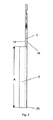
図2は、図1による骨安定化手段を示す側面図である。
図3は、図1による骨安定化手段を示す前面図である。
図4は、図1〜3による骨安定化手段のアームの部分を示す断面図である。
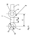
図5は、図1〜3による骨安定化手段のアームを示す図である。
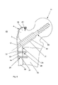
図6は、図1〜5による骨安定化手段と、大腿部に取付けられている骨プレートを含んで成るケース接合部とを有する転子安定化装置を示す縦断面図である。
(Brief description of the drawings)
FIG. 1 is a diagram showing bone stabilization means of an embodiment of a trochanter stabilization device according to the present invention.
FIG. 2 is a side view showing the bone stabilization means according to FIG.
FIG. 3 is a front view showing the bone stabilization means according to FIG.
4 is a cross-sectional view showing the arm portion of the bone stabilization means according to FIGS.
FIG. 5 shows the arm of the bone stabilization means according to FIGS.
FIG. 6 is a longitudinal sectional view showing a trochanter stabilization device having the bone stabilization means according to FIGS. 1 to 5 and a case joint comprising a bone plate attached to the thigh.
図1〜4によれば、長手方向軸8と、外側の骨10に向いた表面18と、内側表面19と、長手方向軸8に対して展開され、または曲げられる4つの末梢のアーム4とを有する骨安定化手段1は実質的に中央プレート2を含んで成る。中央プレート2は、長手方向軸8に対して平行に長さL、およびこれに対して横方向に幅Bを有し、ここでB<Lである。さらに、中央プレート2は、外側表面18から内側表面19までプレート2を貫通する長穴3、同じく貫通する複数の固定孔13、および同じく貫通する、長穴3に入る開口17を備えている。アーム4は、長手方向軸8と交わるプレート2の第1の端25に配置されている。それによって、プレート2はその第1の端25にフォーク状に構成されており、フォークの先端27にはそれぞれ穴5を有するケース16を備えており、末端には弓状のクロスバー28を含んで成り、これは両方のフォーク先端27を結合し、それぞれ穴5を有する2つのケース16を有する。2つのアーム4a、4bの固定端はフォーク先端27においてケース16と結合されているが、他の2つのアーム4c、4dの固定端21はクロスバー28においてケース16と結合されている。それによって、アーム4a〜4dは、フォーク先端27のケース16と結合された2つのアーム4a、4bが長手方向軸8と約110°の角度を含むが、クロスバー28においてケース16と結合された2つのアーム4c、4dは長手方向軸8と約35°の角度を含むように配置されている。
1-4, a longitudinal axis 8, a
固定孔13は、それによって骨安定化手段1がケース接合部29(図6)の骨プレート30とともに骨10において固定可能である固定骨固定手段20、特に骨ネジを受入れるために使用される。開口17は長穴として構成されており、必要に応じて追加の骨ネジ(図示せず)が挿入されうる。この追加の骨ネジによって股関節頭の大腿骨に対するねじれが阻止される。例えば股関節ネジまたはらせんブレードとして構成されうる固定要素50(図6)は、軸方向の転位に際してその後方端で長穴3へ避けることができる。
アーム4は、この場合、それぞれ自由端22に配置されたケース16と、それぞれケース16と固定端21との間に配置されたブリッジ7とで構成され、ここでケース16は厚さDを有し、かつブリッジ7はより小さな厚さdを有し、ブリッジ7は曲げ可能であるが、それによってケース16および特にその中の雌ネジ6が変形されない。ケース16における穴5は円錐状に構成されており、円錐状の雌ネジを備えている。
さらに、中央プレート2には長手方向軸8に対して平行にプレート2の第2の端26から長さAで測定される、2つのガイドレール9が取付けられており、これによって中央プレート2はその長手方向軸8に対して平行にケース接合部29(図6)の
骨10に固定された骨プレート30上を、アーム4が大転子12(図6)の表面に接するまで移動可能である。
The fixation holes 13 are used for receiving fixed bone fixation means 20, in particular bone screws, by which the bone stabilization means 1 can be fixed in the
The
Furthermore, two
アーム4の1つの部分が図5に示されている。市販されている切断器具、例えば踵骨プレートのセットによる切断器具(AOナンバー329.142)が使用されうるために、穴5およびブリッジ7を有するケース16の寸法は以下のように選択されている。すなわち、
−2つの隣接した穴5の2つの中心間の距離Cは14mmであり、
−2つの隣接したケース16間の距離Wは6mmであり、かつ
−ケース16の外径DAは8mmである。
One part of the
-The distance C between the two centers of two
- Two distance W between
転子安定化装置40の図6に示されている実施形態は、大腿骨頸部および特に大腿骨の転子骨折の管理のために使用される従来のケース接合部29、および転子安定化プレートとして構成された中央プレート2から実質的に成り、中央プレート2の長手方向軸8に対して曲げられた4つの末梢のアーム4を有する(図1−4)。アーム4のブリッジ7(図1)は、アーム4が大転子12の表面に接するように曲げられうる。ケース接合部29は、骨10、特に大腿骨骨幹軸と結合可能な、大腿骨骨幹軸の長手方向軸に対して平行に走る一連の固定孔33を備えた骨プレート30と、そこにある角度で位置する、固定要素50、特に股関節ネジまたはらせんブレードが通過可能であるガイドケース31とを含んで成る。固定孔33は、好ましくは、離れて配置されており、皿穴14が備えられている。骨プレート30の骨における固定には骨ネジとして構成された骨固定手段20も使用可能である。アーチ形の骨表面への良好な解剖学的適合には骨プレート30が骨表面へ適合される中空円筒部として構成されている。
ガイドレール9によって骨プレート30および中央プレート2は、中央プレート2における固定孔13が骨プレート30における固定孔33と整列するまで、互いに対して、かつ長手方向軸8に対して平行に移動されうるため、中央プレート2は骨プレート30においてネジ込まれる骨固定手段、特に骨ネジの一部によってケース接合部29に固定可能である。
The embodiment shown in FIG. 6 of the
By means of the
骨プレート30を移植する従来の手術法は、以下の点にある。すなわち、
−器具によって作業過程において側方内側方向で大転子の下部に固定要素50、およびケース接合部29に取付けられるガイドケース31を大腿骨頸部の中心へ挿入するために異なる直径の複数の穴を取付け、
−次いで、固定要素50を大腿骨頸部へ挿入し、ここで照準器によって正確なネジ込み深さが決定され、
−その後にケース接合部29のガイドケースのガイドケース31を固定要素50上を押して動かし、
−ケース接合部29を骨ネジとして構成された骨固定手段20によって骨軸に固定し、ここでケース接合部29の第1および第3の固定孔33は空のままにされ、
−転子プレートのアーム4を適切な装置によって存在する骨折形態に応じて正しく切断し、正しく曲げ、
−次いで、中央プレート2を中央プレート20および骨プレート30を貫通する固定孔13、33を介して骨ネジとして構成された骨固定手段20によってすでに移植されたケース接合部29に取付け、
−必要に応じて、骨安定化手段1の開口17を介して、頭部断片と大腿骨骨幹軸との間の相対運動を阻止する少なくとも6.5mmの直径を有する骨ネジを挿入することができる。それによって、骨安定化手段1を逆圧として使用し、頭部断片を横方向へ引き、こうして割れ目を閉鎖することができ、
−次いで、大転子の骨断片を骨固定手段20によって、特にヘッドネジ山を有する角度安定の骨ネジによって固定することができる。骨安定化手段1の穴5における骨ネジに角度安定固定によって、ネジ山間とともに骨断片間の相対運動が阻止される。
転子安定化プレートはその構造上の剛性によりきわめて薄い板金で製造されうる。
The conventional surgical method for implanting the
A plurality of holes of different diameters for inserting into the center of the femoral neck the fixing
-The
-After that, the
Fixing the case joint 29 to the bone axis by means of a bone fixing means 20 configured as a bone screw, wherein the first and third fixing holes 33 of the case joint 29 are left empty,
-The
The central plate 2 is then attached to the case joint 29 already implanted by the bone anchoring means 20 configured as a bone screw via the fixing holes 13, 33 penetrating the
-Optionally inserting a bone screw having a diameter of at least 6.5 mm that prevents relative movement between the head fragment and the femoral shaft through the
-The greater trochanter bone fragment can then be fixed by means of the bone anchoring means 20, in particular by means of an angle-stable bone screw with a head thread. Relative movement between the bone fragments as well as between the threads is prevented by angle-stabilizing the bone screw in the
The trochanter stabilization plate can be made of very thin sheet metal due to its structural rigidity.
1 骨安定化手段 2 中央プレート 3 長穴
4 アーム 8 長手方向軸 10 外側の骨
13 固定孔 16 ケース 17 開口
18 表面 19 内側表面 20 骨固定手段
25 第1の端 27 フォークの先端 30 骨プレート
40 転子安定化装置 50 固定要素
DESCRIPTION OF
Claims (20)
B)股関節(11)の範囲へ導入される固定要素(50)を受入れるためにある角度で位置するケース(31)が固定される長手方向の骨プレート(30)と
を有する特に股関節(11)の範囲における骨断片の固定または大転子(12)の固定のための転子安定化装置(40)において、
C)前記中央プレート(2)から少なくとも3つの周辺アーム(4)が発し、
D)各周辺アーム(4)が少なくとも1つの穴(5)を介して骨固定手段(20)を受入れるために使用され、かつ
E)前記穴(5)の少なくとも一部が雌ネジ(6)を備えている
ことを特徴とする転子安定化装置(40)。 A) bone stabilization means (1) comprising a central plate (2) having at least one fixation hole (13) for receiving the bone fixation means (20);
B) In particular the hip joint (11) with a longitudinal bone plate (30) to which a case (31) situated at an angle is received for receiving a fixation element (50) introduced into the area of the hip joint (11) In a trochanter stabilization device (40) for fixation of bone fragments or fixation of the greater trochanter (12) in the range of
C) At least three peripheral arms (4) emanating from the central plate (2),
D) each peripheral arm (4) is used to receive bone anchoring means (20) via at least one hole (5), and E) at least part of said hole (5) is internally threaded (6) A trochanter stabilization device (40) comprising:
20. A trochanter stabilization device (40) according to any one of claims 1 to 19 and a fixing element (50), wherein the fixing element (50) is a hip screw or a helical blade. Hip joint screw device.
Applications Claiming Priority (1)
| Application Number | Priority Date | Filing Date | Title |
|---|---|---|---|
| PCT/CH2003/000604 WO2005023127A1 (en) | 2003-09-08 | 2003-09-08 | Bone fixing device |
Publications (1)
| Publication Number | Publication Date |
|---|---|
| JP2007506452A true JP2007506452A (en) | 2007-03-22 |
Family
ID=34230816
Family Applications (1)
| Application Number | Title | Priority Date | Filing Date |
|---|---|---|---|
| JP2005508661A Pending JP2007506452A (en) | 2003-09-08 | 2003-09-08 | Bone fixation device |
Country Status (14)
| Country | Link |
|---|---|
| US (1) | US8147493B2 (en) |
| EP (1) | EP1682020B1 (en) |
| JP (1) | JP2007506452A (en) |
| KR (1) | KR101050877B1 (en) |
| CN (1) | CN100475168C (en) |
| AT (1) | ATE375762T1 (en) |
| AU (1) | AU2003257355B2 (en) |
| BR (1) | BR0318477B8 (en) |
| CA (1) | CA2538117C (en) |
| DE (1) | DE50308440D1 (en) |
| ES (1) | ES2295708T3 (en) |
| NZ (1) | NZ545743A (en) |
| TW (1) | TWI345965B (en) |
| WO (1) | WO2005023127A1 (en) |
Cited By (1)
| Publication number | Priority date | Publication date | Assignee | Title |
|---|---|---|---|---|
| JP2020509860A (en) * | 2017-03-13 | 2020-04-02 | デピュイ・シンセス・プロダクツ・インコーポレイテッド | Proximal femoral hook plate |
Families Citing this family (86)
| Publication number | Priority date | Publication date | Assignee | Title |
|---|---|---|---|---|
| US8475504B2 (en) * | 2007-07-19 | 2013-07-02 | Acumed Llc | Method of bone fixation with slender spanning members disposed outside bone |
| GB0307648D0 (en) * | 2003-04-02 | 2003-05-07 | Benoist Girard Sas | Greater trochanter re-attachment device |
| US7951176B2 (en) | 2003-05-30 | 2011-05-31 | Synthes Usa, Llc | Bone plate |
| WO2005018472A1 (en) | 2003-08-26 | 2005-03-03 | Synthes Gmbh | Bone plate |
| US11259851B2 (en) | 2003-08-26 | 2022-03-01 | DePuy Synthes Products, Inc. | Bone plate |
| ATE428362T1 (en) * | 2003-10-30 | 2009-05-15 | Synthes Gmbh | BONE PLATE |
| EP1684651A1 (en) * | 2003-11-05 | 2006-08-02 | Königsee Implantate und Instrumente zur Ostheosynthese GmbH | Plate used to stabilise distal radius fractures |
| US8182485B1 (en) | 2003-11-21 | 2012-05-22 | Toby Orthopaedics, Llc | Fracture fixation system |
| US7637928B2 (en) | 2004-01-26 | 2009-12-29 | Synthes Usa, Llc | Variable angle locked bone fixation system |
| US11291484B2 (en) | 2004-01-26 | 2022-04-05 | DePuy Synthes Products, Inc. | Highly-versatile variable-angle bone plate system |
| US8574268B2 (en) | 2004-01-26 | 2013-11-05 | DePuy Synthes Product, LLC | Highly-versatile variable-angle bone plate system |
| US8172886B2 (en) | 2004-12-14 | 2012-05-08 | Depuy Products, Inc. | Bone plate with pre-assembled drill guide tips |
| WO2007035713A2 (en) * | 2005-09-16 | 2007-03-29 | Small Bone Innovations, Inc. | Condylar plate |
| JP2009509660A (en) * | 2005-09-28 | 2009-03-12 | スミス アンド ネフュー インコーポレーテッド | Equipment for reducing femoral neck fractures |
| US7935126B2 (en) | 2006-03-20 | 2011-05-03 | Depuy Products, Inc. | Bone plate shaping system |
| CA2643908A1 (en) * | 2006-04-13 | 2007-10-25 | Arno Smit | Hip protector implant |
| JP5176153B2 (en) * | 2006-08-15 | 2013-04-03 | スイスメドテヒソリューションズ アーゲー | Trochanter holding plate |
| US8267972B1 (en) * | 2006-12-01 | 2012-09-18 | Gehlert Rick J | Bone plate |
| US8398687B2 (en) * | 2006-12-06 | 2013-03-19 | Amei Technologies, Inc. | Volar plate fixation device |
| US7678147B2 (en) | 2007-05-01 | 2010-03-16 | Moximed, Inc. | Extra-articular implantable mechanical energy absorbing systems and implantation method |
| US8088166B2 (en) | 2007-05-01 | 2012-01-03 | Moximed, Inc. | Adjustable absorber designs for implantable device |
| US9907645B2 (en) | 2007-05-01 | 2018-03-06 | Moximed, Inc. | Adjustable absorber designs for implantable device |
| US20100137996A1 (en) | 2007-05-01 | 2010-06-03 | Moximed, Inc. | Femoral and tibial base components |
| US20080275567A1 (en) | 2007-05-01 | 2008-11-06 | Exploramed Nc4, Inc. | Extra-Articular Implantable Mechanical Energy Absorbing Systems |
| US20110245928A1 (en) | 2010-04-06 | 2011-10-06 | Moximed, Inc. | Femoral and Tibial Bases |
| US9655648B2 (en) | 2007-05-01 | 2017-05-23 | Moximed, Inc. | Femoral and tibial base components |
| US8894714B2 (en) | 2007-05-01 | 2014-11-25 | Moximed, Inc. | Unlinked implantable knee unloading device |
| US8449581B2 (en) * | 2007-05-07 | 2013-05-28 | Stryker Trauma Gmbh | Sliding plate with reinforced slot |
| EP2397093B1 (en) | 2007-11-02 | 2015-12-02 | Biomet C.V. | Elbow fracture fixation system |
| WO2009064643A1 (en) * | 2007-11-13 | 2009-05-22 | Synthes (U.S.A) | Periprosthetic fracture repair |
| US8317842B2 (en) * | 2007-11-30 | 2012-11-27 | Biomet C.V. | Distal tibia plating system |
| EP2252224A4 (en) | 2008-03-10 | 2012-06-06 | Gonzalez Hernandez Eduardo | Bone fixation system |
| US20090264936A1 (en) | 2008-04-17 | 2009-10-22 | Eduardo Gonzalez-Hernandez | Soft tissue attachment system and clip |
| US8628533B2 (en) * | 2008-05-08 | 2014-01-14 | The Cleveland Clinic Foundation | Bone plate with reduction aids and methods of use thereof |
| CA2643678C (en) * | 2008-06-12 | 2016-01-19 | Socovar, Societe En Commandite | Orthopaedic fixation component and method |
| US8282674B2 (en) * | 2008-07-18 | 2012-10-09 | Suspension Orthopaedic Solutions, Inc. | Clavicle fixation |
| US9107712B2 (en) * | 2008-09-15 | 2015-08-18 | Biomet C.V. | Bone plate system for hand fractures and other small bones |
| WO2011075757A1 (en) * | 2008-12-23 | 2011-06-30 | Austofix Group Pty Ltd | Fixation elements for fixation plates |
| US8808333B2 (en) | 2009-07-06 | 2014-08-19 | Zimmer Gmbh | Periprosthetic bone plates |
| US8834532B2 (en) * | 2009-07-07 | 2014-09-16 | Zimmer Gmbh | Plate for the treatment of bone fractures |
| US10349980B2 (en) | 2009-08-27 | 2019-07-16 | The Foundry, Llc | Method and apparatus for altering biomechanics of the shoulder |
| CN116570353A (en) | 2009-08-27 | 2023-08-11 | 铸造有限责任公司 | Device for changing the load between the patella and the femur in a knee joint and for treating hip joint diseases |
| US9861408B2 (en) | 2009-08-27 | 2018-01-09 | The Foundry, Llc | Method and apparatus for treating canine cruciate ligament disease |
| US9668868B2 (en) | 2009-08-27 | 2017-06-06 | Cotera, Inc. | Apparatus and methods for treatment of patellofemoral conditions |
| US9278004B2 (en) | 2009-08-27 | 2016-03-08 | Cotera, Inc. | Method and apparatus for altering biomechanics of the articular joints |
| WO2011032140A1 (en) | 2009-09-14 | 2011-03-17 | Synthes Usa, Llc | Variable angle compression plate |
| US20110087229A1 (en) * | 2009-10-12 | 2011-04-14 | University Of Utah | Bone fixation and compression systems |
| US8657820B2 (en) | 2009-10-12 | 2014-02-25 | Tornier, Inc. | Bone plate and keel systems |
| US20110152943A1 (en) * | 2009-12-22 | 2011-06-23 | Eduardo Gonzalez-Hernandez | Bone plate and tool assembly and method for use thereof |
| US20110218580A1 (en) * | 2010-03-08 | 2011-09-08 | Stryker Trauma Sa | Bone fixation system with curved profile threads |
| US8961573B2 (en) | 2010-10-05 | 2015-02-24 | Toby Orthopaedics, Inc. | System and method for facilitating repair and reattachment of comminuted bone portions |
| US8518042B2 (en) | 2010-10-19 | 2013-08-27 | Biomet Manufacturing, Llc | Orthopedic plate assembly for a distal radius having re-contouring features and method for using same |
| US8870963B2 (en) | 2010-10-27 | 2014-10-28 | Toby Orthopaedics, Inc. | System and method for fracture replacement of comminuted bone fractures or portions thereof adjacent bone joints |
| WO2012119146A2 (en) | 2011-03-03 | 2012-09-07 | Toby Orthopaedics, Llc | Anterior lesser tuberosity fixed angle fixation device and method of use associated therewith |
| US9044270B2 (en) | 2011-03-29 | 2015-06-02 | Moximed, Inc. | Apparatus for controlling a load on a hip joint |
| DE102011116732A1 (en) | 2011-09-02 | 2013-03-07 | Königsee Implantate GmbH | Device for fixing a bone fractured in the region of the femoral neck |
| US9271772B2 (en) | 2011-10-27 | 2016-03-01 | Toby Orthopaedics, Inc. | System and method for fracture replacement of comminuted bone fractures or portions thereof adjacent bone joints |
| US9730797B2 (en) | 2011-10-27 | 2017-08-15 | Toby Orthopaedics, Inc. | Bone joint replacement and repair assembly and method of repairing and replacing a bone joint |
| US9402667B2 (en) | 2011-11-09 | 2016-08-02 | Eduardo Gonzalez-Hernandez | Apparatus and method for use of the apparatus for fracture fixation of the distal humerus |
| CN102551921B (en) * | 2012-01-13 | 2014-07-02 | 南方医科大学 | Artificial femoral stem for fracture surgery around hip joint prosthesis |
| US9681902B2 (en) | 2012-02-13 | 2017-06-20 | Stryker European Holdings I, Llc | Attachment device for a bone plate |
| US9468466B1 (en) | 2012-08-24 | 2016-10-18 | Cotera, Inc. | Method and apparatus for altering biomechanics of the spine |
| US9101426B2 (en) | 2012-10-11 | 2015-08-11 | Stryker Trauma Sa | Cable plug |
| US9283008B2 (en) | 2012-12-17 | 2016-03-15 | Toby Orthopaedics, Inc. | Bone plate for plate osteosynthesis and method for use thereof |
| US9333014B2 (en) | 2013-03-15 | 2016-05-10 | Eduardo Gonzalez-Hernandez | Bone fixation and reduction apparatus and method for fixation and reduction of a distal bone fracture and malunion |
| CN103156676A (en) * | 2013-03-26 | 2013-06-19 | 江苏荷普医疗器械有限公司 | Tibia far-end inner-side steel plate |
| CN103919599A (en) * | 2014-04-17 | 2014-07-16 | 泰州市中兴医械科技有限公司 | Humerus Y-type protection steel board |
| US10499968B2 (en) | 2014-08-08 | 2019-12-10 | Stryker European Holdings I, Llc | Cable plugs for bone plates |
| CN104188717A (en) * | 2014-09-24 | 2014-12-10 | 苏州欣荣博尔特医疗器械有限公司 | Claw-shaped greater trochanter locking bone fracture plate with side wings |
| US9463053B2 (en) * | 2014-12-08 | 2016-10-11 | Jonathan P. GARINO | Fracture plating |
| US9339313B1 (en) * | 2015-05-20 | 2016-05-17 | Roy Y. Powlan | Hip fracture support plate |
| US10905478B2 (en) | 2015-09-04 | 2021-02-02 | DePuy Synthes Products, Inc. | Patella bone plate and methods of fixation |
| CN105640635B (en) * | 2016-02-03 | 2018-08-31 | 哈尔滨医科大学 | A kind of Periprosthetic Fracture After Total Hip Arthroplasty overhauls locking steel plate |
| CN106344140B (en) * | 2016-08-23 | 2018-11-30 | 江苏奥康尼医疗科技发展有限公司 | A kind of near end of thighbone bone plate |
| US10820930B2 (en) | 2016-09-08 | 2020-11-03 | DePuy Synthes Products, Inc. | Variable angle bone plate |
| US10905476B2 (en) | 2016-09-08 | 2021-02-02 | DePuy Synthes Products, Inc. | Variable angle bone plate |
| US10624686B2 (en) | 2016-09-08 | 2020-04-21 | DePuy Synthes Products, Inc. | Variable angel bone plate |
| WO2018064779A1 (en) * | 2016-10-04 | 2018-04-12 | Suratec Gmbh | Modular osteosynthesis implant assembly |
| US10499966B2 (en) | 2017-10-24 | 2019-12-10 | DePuy Synthes Products, Inc. | Bone fixation system including an implant having a plate portion and a mesh portion |
| US11026727B2 (en) | 2018-03-20 | 2021-06-08 | DePuy Synthes Products, Inc. | Bone plate with form-fitting variable-angle locking hole |
| US10772665B2 (en) | 2018-03-29 | 2020-09-15 | DePuy Synthes Products, Inc. | Locking structures for affixing bone anchors to a bone plate, and related systems and methods |
| US11013541B2 (en) | 2018-04-30 | 2021-05-25 | DePuy Synthes Products, Inc. | Threaded locking structures for affixing bone anchors to a bone plate, and related systems and methods |
| EP3581131B8 (en) * | 2018-06-15 | 2023-03-01 | Stryker European Operations Holdings LLC | Trochanter plates |
| US10765462B2 (en) | 2018-09-11 | 2020-09-08 | DePuy Synthes Products, Inc. | Patella bone plate and methods of fixation |
| US10945850B2 (en) * | 2018-10-25 | 2021-03-16 | Revision Technologies Llc | Interconnected implants and methods |
| US10925651B2 (en) | 2018-12-21 | 2021-02-23 | DePuy Synthes Products, Inc. | Implant having locking holes with collection cavity for shavings |
Citations (6)
| Publication number | Priority date | Publication date | Assignee | Title |
|---|---|---|---|---|
| JPH0321149U (en) * | 1989-06-02 | 1991-03-01 | ||
| JPH05184594A (en) * | 1991-05-30 | 1993-07-27 | Synthes Ag | Trochanter-stabilizing device |
| JPH11299804A (en) * | 1998-04-16 | 1999-11-02 | Homuzu Giken:Kk | Osteosynthesis device |
| WO2001019267A1 (en) * | 1999-09-13 | 2001-03-22 | Synthes Ag Chur | Bone plate system |
| JP2002537937A (en) * | 1999-03-09 | 2002-11-12 | ジンテーズ アクチエンゲゼルシャフト クール | Bone plate |
| JP2002345836A (en) * | 2001-04-20 | 2002-12-03 | Depuy Products Inc | Polyaxial locking plate |
Family Cites Families (156)
| Publication number | Priority date | Publication date | Assignee | Title |
|---|---|---|---|---|
| FR742618A (en) | 1933-03-10 | |||
| US2406832A (en) * | 1945-03-05 | 1946-09-03 | Mervyn G Hardinge | Fracture plate |
| US2612159A (en) | 1949-03-01 | 1952-09-30 | Marie B Collison | Trochanteric plate for bone surgery |
| US3463148A (en) | 1966-01-20 | 1969-08-26 | Richards Mfg Co | Bone plate |
| CH462375A (en) | 1966-06-22 | 1968-09-15 | Synthes Ag | Osteosynthetic pressure plate |
| USRE31628E (en) | 1966-06-22 | 1984-07-10 | Synthes Ag | Osteosynthetic pressure plate construction |
| USRE28841E (en) | 1966-06-22 | 1976-06-08 | Synthes A.G. | Osteosynthetic pressure plate construction |
| US3630261A (en) | 1968-02-27 | 1971-12-28 | Rex Chainbelt Inc | Frictional antirotation device |
| US3716050A (en) | 1971-02-11 | 1973-02-13 | F Johnston | Olecranon plate |
| US3741205A (en) | 1971-06-14 | 1973-06-26 | K Markolf | Bone fixation plate |
| US3779240A (en) | 1972-03-31 | 1973-12-18 | S Kondo | Compression plate for osteosynthesis |
| FR2233973A1 (en) | 1973-06-25 | 1975-01-17 | Chatin Robert | Osteosynthesis plate for femoral fracture surgery - has anchoring holes in ablong flat portion and widened blade |
| DE2438669C3 (en) | 1974-08-12 | 1978-10-05 | Bezold Geb. Graefin Von Sponeck, Margarete Von, 8035 Gauting | Osteosynthesis plate |
| CH611147A5 (en) | 1977-01-07 | 1979-05-31 | Mueller Kurt | Osteosynthesis compression plate |
| US4095591A (en) | 1977-01-27 | 1978-06-20 | Richards Manufacturing Co., Inc. | Compression screw system |
| GB1565178A (en) | 1977-02-24 | 1980-04-16 | Interfix Ltd | Bone screw |
| CH613858A5 (en) | 1977-04-22 | 1979-10-31 | Straumann Inst Ag | |
| FR2405062A1 (en) | 1977-10-10 | 1979-05-04 | Dayan Robert | Surgical repair plate for lower fractures of femur - has concave cross section and enlarged end with staggered countersunk screw holes |
| FR2405705A1 (en) | 1977-10-14 | 1979-05-11 | Dayan Robert | Surgical repair plate for tibia upper end fracture - has elongated length with enlarged head and countersunk for fixing screws |
| FR2405706A1 (en) | 1977-10-14 | 1979-05-11 | Dayan Robert | Surgical repair plate for humerus lower end fracture - has end with unequal curved branches and countersunk holes for fixing screws |
| FR2416683A1 (en) | 1978-02-10 | 1979-09-07 | Judet Robert | IMPROVEMENTS TO OSTEO-SYNTHESIS DEVICES |
| CA1112803A (en) | 1978-08-17 | 1981-11-24 | George W. Bagby | Internal fracture plate assembly with releasing feature |
| CH645013A5 (en) | 1980-04-14 | 1984-09-14 | Wenk Wilh Ag | Osteosynthetic COMPRESSION PLATE. |
| CH648197A5 (en) | 1980-05-28 | 1985-03-15 | Synthes Ag | IMPLANT AND SCREW FASTENING ON ITS BONE. |
| IT1132843B (en) | 1980-09-15 | 1986-07-09 | Cise Spa | PLATE FOR JOINTS OF SEPARATE BONE PORTIONS FROM FRACTURE |
| CH651192A5 (en) | 1980-11-20 | 1985-09-13 | Synthes Ag | OSTEOSYNTHETIC DEVICE AND CORRESPONDING DRILL GAUGE. |
| US4338926A (en) | 1980-11-21 | 1982-07-13 | Howmedica, Inc. | Bone fracture prosthesis with controlled stiffness |
| DE8034274U1 (en) | 1980-12-23 | 1981-05-27 | Schwan-Stabilo Schwanhäußer GmbH & Co, 8500 Nürnberg | COSMETIC PEN |
| CH650915A5 (en) | 1981-03-16 | 1985-08-30 | Synthes Ag | DEVICE FOR STABILIZING THE AREA OF A BONE BREAK OR OSTEOTOMY. |
| SU1037911A1 (en) | 1981-08-27 | 1983-08-30 | Kobzev Ernest V | Apparatus for extracortical osteosynthesis |
| US4530355A (en) | 1982-01-18 | 1985-07-23 | Richards Manufacturing Co., Inc. | Compression screw assembly |
| US4432358A (en) | 1982-01-22 | 1984-02-21 | Fixel Irving E | Compression hip screw apparatus |
| AT378324B (en) | 1982-09-13 | 1985-07-25 | Streli Elke | TINNED PLATE FOR FIXING THE BONES IN THE BODIES IN BONE BREAKS |
| US4612923A (en) | 1983-12-01 | 1986-09-23 | Ethicon, Inc. | Glass-filled, absorbable surgical devices |
| CH662936A5 (en) | 1984-05-18 | 1987-11-13 | Technomed Gmk | BONE JOINT PLATE. |
| US4657001A (en) | 1984-07-25 | 1987-04-14 | Fixel Irving E | Antirotational hip screw |
| DE8431616U1 (en) | 1984-10-27 | 1984-12-20 | Howmedica International, Inc. Zweigniederlassung Kiel, 2314 Schönkirchen | Plate for osteosynthesis |
| US4612920A (en) | 1984-11-06 | 1986-09-23 | Zimmer, Inc. | Compression hip screw |
| DE3442004C1 (en) | 1984-11-16 | 1986-04-24 | Otte, Heinz, Dr.med., 8712 Volkach | Bone fixation apparatus for the treatment of fractures |
| US4683878A (en) | 1985-04-29 | 1987-08-04 | Kirschner Medical Corporation | Osteosynthetic fixation plate |
| SU1279626A1 (en) | 1985-06-06 | 1986-12-30 | Центральный научно-исследовательский институт травматологии и ортопедии им.Н.Н.Приорова | Compression device for osteosynthesis |
| DE8519854U1 (en) | 1985-07-05 | 1986-04-30 | Mecron Medizinische Produkte Gmbh, 1000 Berlin | Self-tightening straight bone plate |
| US5013315A (en) | 1985-07-12 | 1991-05-07 | Minnesota Mining And Manufacturing Company | Semiabsorbable bone plate spacer |
| CH668174A5 (en) | 1985-08-30 | 1988-12-15 | Synthes Ag | OSTEOSYNTHETIC PRINT PLATE. |
| US4776329A (en) | 1985-09-20 | 1988-10-11 | Richards Medical Company | Resorbable compressing screw and method |
| PL147580B1 (en) | 1986-04-14 | 1989-06-30 | Plate for uniting epiphysis and diaphysis of broken bone | |
| US5190544A (en) | 1986-06-23 | 1993-03-02 | Pfizer Hospital Products Group, Inc. | Modular femoral fixation system |
| US4776330A (en) | 1986-06-23 | 1988-10-11 | Pfizer Hospital Products Group, Inc. | Modular femoral fixation system |
| US4781183A (en) | 1986-08-27 | 1988-11-01 | American Cyanamid Company | Surgical prosthesis |
| JPH02500490A (en) | 1986-11-25 | 1990-02-22 | シンセス アクチエン ゲゼルシャフト | osteosynthesis device |
| WO1989004150A1 (en) | 1987-11-03 | 1989-05-18 | Synthes Ag | Implant for osteosynthesis |
| US5151103A (en) | 1987-11-03 | 1992-09-29 | Synthes (U.S.A.) | Point contact bone compression plate |
| CH673762A5 (en) | 1987-12-02 | 1990-04-12 | Synthes Ag | |
| US4858601A (en) | 1988-05-27 | 1989-08-22 | Glisson Richard R | Adjustable compression bone screw |
| DE8807909U1 (en) * | 1988-06-18 | 1988-10-20 | Howmedica Gmbh, 2314 Schoenkirchen, De | |
| DE8808123U1 (en) * | 1988-06-24 | 1988-09-22 | Herzberg, Wolfgang, Dr. Med., 2000 Wedel, De | |
| US4973332A (en) * | 1988-09-12 | 1990-11-27 | Hospital For Joint Diseases | Attachment for femur sliding screw plate |
| DE8900121U1 (en) | 1989-01-04 | 1990-02-15 | Mecron Medizinische Produkte Gmbh, 1000 Berlin, De | |
| IT1232572B (en) | 1989-02-10 | 1992-02-26 | Calderale Pasquale Mario | MEANS OF OSTEOSYNTHESIS FOR THE CONNECTION OF BONE FRACTURE SEGMENTS |
| US4927421A (en) | 1989-05-15 | 1990-05-22 | Marlowe Goble E | Process of endosteal fixation of a ligament |
| DE3923995A1 (en) | 1989-07-20 | 1991-01-31 | Lutz Biedermann | BONE STABILIZING ELEMENT |
| US5006120A (en) | 1989-10-10 | 1991-04-09 | Carter Peter R | Distal radial fracture set and method for repairing distal radial fractures |
| US5032125A (en) | 1990-02-06 | 1991-07-16 | Smith & Nephew Richards Inc. | Intramedullary hip screw |
| US5085660A (en) | 1990-11-19 | 1992-02-04 | Lin Kwan C | Innovative locking plate system |
| US5514138A (en) | 1991-02-08 | 1996-05-07 | Pfizer Inc. | Connector having a stop member |
| FR2674118B1 (en) | 1991-03-19 | 1998-02-20 | Benoit Girard Cie Sa | SPINAL OSTEOSYNTHESIS DEVICE. |
| US5129901A (en) | 1991-06-10 | 1992-07-14 | Decoste Vern X | Cannulated orthopedic screw |
| GB9113578D0 (en) | 1991-06-24 | 1991-08-14 | Howmedica | Intramedullary intertrochanteric fracture fixation appliance |
| US5275601A (en) | 1991-09-03 | 1994-01-04 | Synthes (U.S.A) | Self-locking resorbable screws and plates for internal fixation of bone fractures and tendon-to-bone attachment |
| US5360448A (en) | 1991-10-07 | 1994-11-01 | Thramann Jeffrey J | Porous-coated bone screw for securing prosthesis |
| CH686339A5 (en) | 1991-12-10 | 1996-03-15 | Synthes Ag | Nut for the plate fixation. |
| US5304180A (en) | 1992-01-17 | 1994-04-19 | Slocum D Barclay | Tibial osteotomy fixation plate |
| US5360429A (en) * | 1992-02-20 | 1994-11-01 | Jbs Societe Anonyme | Device for straightening, fixing, compressing, and elongating cervical vertebrae |
| US5197966A (en) | 1992-05-22 | 1993-03-30 | Sommerkamp T Greg | Radiodorsal buttress blade plate implant for repairing distal radius fractures |
| DE59208301D1 (en) | 1992-06-25 | 1997-05-07 | Synthes Ag | OSTEOSYNTHETIC FIXATION DEVICE |
| US5324290A (en) | 1992-09-24 | 1994-06-28 | Danek Medical, Inc. | Anterior thoracolumbar plate |
| US5336224A (en) * | 1992-11-30 | 1994-08-09 | Ace Medical Company | Bone fixation plate |
| JP3386812B2 (en) | 1993-01-25 | 2003-03-17 | ジンテーズ アクチエンゲゼルシャフト,クール | Reverse tightening disc for plate osteosynthesis |
| US5364399A (en) | 1993-02-05 | 1994-11-15 | Danek Medical, Inc. | Anterior cervical plating system |
| IL105183A (en) | 1993-03-28 | 1996-07-23 | Yehiel Gotfried | Surgical device for connection of fractured bones |
| FR2711505B1 (en) | 1993-10-25 | 1995-12-29 | Tornier Sa | Device for synthesizing fractures of the upper end of the femur. |
| DE4341980B4 (en) | 1993-12-09 | 2005-02-17 | Königsee Implantate und Instrumente zur Ostheosynthese GmbH | Osteosynthetic bone plate |
| DE9321544U1 (en) | 1993-12-09 | 1999-09-23 | Koenigsee Implantate & Instr | Osteosynthetic plate |
| DE4343117C2 (en) | 1993-12-17 | 1999-11-04 | Dietmar Wolter | Bone fixation system |
| WO1995032674A1 (en) | 1994-06-01 | 1995-12-07 | Synthes Ag, Chur | Forked bone plate |
| US5591169A (en) * | 1994-06-14 | 1997-01-07 | Benoist; Louis | Device and method for positioning and holding bone fragments in place |
| SE9402130D0 (en) | 1994-06-17 | 1994-06-17 | Sven Olerud | Device and method for plate fixation of legs |
| DE4438264C2 (en) | 1994-09-08 | 1996-11-28 | Schaefer Micomed Gmbh | Osteosynthesis device |
| US5810823A (en) | 1994-09-12 | 1998-09-22 | Synthes (U.S.A.) | Osteosynthetic bone plate and lock washer |
| US5601553A (en) | 1994-10-03 | 1997-02-11 | Synthes (U.S.A.) | Locking plate and bone screw |
| US5976141A (en) | 1995-02-23 | 1999-11-02 | Synthes (U.S.A.) | Threaded insert for bone plate screw hole |
| JP3542133B2 (en) | 1995-03-27 | 2004-07-14 | ジンテーズ アクチエンゲゼルシャフト,クール | Bone plate |
| US5520690A (en) * | 1995-04-13 | 1996-05-28 | Errico; Joseph P. | Anterior spinal polyaxial locking screw plate assembly |
| US5607428A (en) | 1995-05-01 | 1997-03-04 | Lin; Kwan C. | Orthopedic fixation device having a double-threaded screw |
| JP3691073B2 (en) | 1995-09-06 | 2005-08-31 | ジンテーズ アクチエンゲゼルシャフト クール | Bone plate |
| US5749872A (en) | 1995-09-08 | 1998-05-12 | Ace Medical Company | Keyed/keyless barrel for bone plates |
| US5868749A (en) | 1996-04-05 | 1999-02-09 | Reed; Thomas M. | Fixation devices |
| US5702399A (en) | 1996-05-16 | 1997-12-30 | Pioneer Laboratories, Inc. | Surgical cable screw connector |
| US5843082A (en) | 1996-05-31 | 1998-12-01 | Acromed Corporation | Cervical spine stabilization method and system |
| EP0909143A4 (en) | 1996-06-14 | 2008-11-26 | Depuy Ace Medical Company | Upper extremity bone plate |
| US5718705A (en) * | 1996-07-16 | 1998-02-17 | Sammarco; Giacomo J. | Internal fixation plate |
| US5690631A (en) * | 1996-09-11 | 1997-11-25 | Walter Lorenz Surgical, Inc. | Multi-configurable plating system |
| US5871548A (en) * | 1996-12-07 | 1999-02-16 | Johnson & Johnson Professional, Inc. | Modular acetabular reinforcement system |
| US5741256A (en) | 1997-01-13 | 1998-04-21 | Synthes (U.S.A.) | Helical osteosynthetic implant |
| EP1006913B2 (en) | 1997-02-11 | 2009-03-11 | Zimmer Spine, Inc. | Anterior cervical plating system |
| US5810821A (en) | 1997-03-28 | 1998-09-22 | Biomet Inc. | Bone fixation screw system |
| US5743913A (en) * | 1997-04-02 | 1998-04-28 | Wellisz; Tadeusz Z. | Readily expansible bone fixation plate |
| FR2766353B1 (en) | 1997-07-28 | 1999-11-26 | Dimso Sa | IMPLANT, ESPECIALLY ANTERIOR CERVICAL PLATE |
| US5954722A (en) | 1997-07-29 | 1999-09-21 | Depuy Acromed, Inc. | Polyaxial locking plate |
| US6004353A (en) * | 1997-07-30 | 1999-12-21 | Medidea, Llc | Modular acetabular reconstruction plate |
| US6454769B2 (en) | 1997-08-04 | 2002-09-24 | Spinal Concepts, Inc. | System and method for stabilizing the human spine with a bone plate |
| EP1006915B1 (en) | 1997-09-04 | 2003-05-21 | SYNTHES AG Chur | Symmetrical bone plate |
| CN2314747Y (en) * | 1997-10-14 | 1999-04-21 | 秦步平 | Big tuberosity reinforced obtuse angle steel plate |
| DE59710521D1 (en) * | 1997-10-20 | 2003-09-04 | Synthes Ag | BONE FIXATION DEVICE |
| US6093188A (en) * | 1997-11-10 | 2000-07-25 | Murray; William M. | Adjustable bone fixation plate |
| US7052499B2 (en) * | 1998-02-18 | 2006-05-30 | Walter Lorenz Surgical, Inc. | Method and apparatus for bone fracture fixation |
| US6129728A (en) * | 1998-02-18 | 2000-10-10 | Walter Lorenz Surgical, Inc. | Method and apparatus for mandibular osteosynthesis |
| US5871485A (en) * | 1998-03-18 | 1999-02-16 | Rao; G.V. Subba | Device for internal fixation of femoral neck fractures |
| US5938664A (en) | 1998-03-31 | 1999-08-17 | Zimmer, Inc. | Orthopaedic bone plate |
| DE1075224T1 (en) | 1998-04-29 | 2001-10-11 | Dimso Sa | SPINE OSTEOSYNTHESIS SYSTEM WITH TENSIONING DEVICE, IN PARTICULAR FOR FRONT FIXING |
| US6139552A (en) | 1998-05-13 | 2000-10-31 | K. K. Hollyx | Bone jointer and a bone jointer fixing tool |
| US6228085B1 (en) | 1998-07-14 | 2001-05-08 | Theken Surgical Llc | Bone fixation system |
| DE19832513A1 (en) | 1998-07-20 | 2000-02-17 | Impag Gmbh Medizintechnik | Fastening arrangement |
| WO1998044849A2 (en) * | 1998-08-25 | 1998-10-15 | Medartis Ag | Osteosynthetic fastening device |
| US6553789B1 (en) * | 1998-10-28 | 2003-04-29 | Schott Glass | Quartz glass plates with high refractive index homogeneity |
| US6183475B1 (en) | 1998-12-18 | 2001-02-06 | Sulzer Orthopedics Inc. | Distal femoral osteotomy system and method |
| DE19858889B4 (en) | 1998-12-19 | 2008-08-07 | Wolter, Dietmar, Prof. Dr.Med. | Fixation system for bones |
| US6129730A (en) | 1999-02-10 | 2000-10-10 | Depuy Acromed, Inc. | Bi-fed offset pitch bone screw |
| AU3954200A (en) | 1999-05-03 | 2000-11-17 | Medartis Ag | Blockable bone plate |
| DE29909025U1 (en) * | 1999-05-25 | 1999-11-04 | Lipat Consulting Ag Basel | Osteosynthetic bone plate |
| DE19944120B4 (en) | 1999-09-15 | 2008-08-28 | Ulrich Gmbh & Co. Kg | Bone screw for variable angle connection with a side member |
| CN2404492Y (en) * | 1999-11-16 | 2000-11-08 | 乔光曦 | End-nearing type supporting steel plate for thighbone |
| BR0017018A (en) | 2000-01-27 | 2002-11-05 | Synthes Ag | Bone plate |
| US6358250B1 (en) | 2000-02-01 | 2002-03-19 | Hand Innovations, Inc. | Volar fixation system |
| US6440135B2 (en) | 2000-02-01 | 2002-08-27 | Hand Innovations, Inc. | Volar fixation system with articulating stabilization pegs |
| US6533789B1 (en) | 2000-04-04 | 2003-03-18 | Synthes (Usa) | Device for rotational stabilization of bone segments |
| US6471706B1 (en) * | 2000-04-18 | 2002-10-29 | Walter Lorenz Surgical, Inc. | Resorbable bone distractor and method |
| US6235033B1 (en) | 2000-04-19 | 2001-05-22 | Synthes (Usa) | Bone fixation assembly |
| CN1184932C (en) * | 2000-06-26 | 2005-01-19 | 库尔斯恩蒂斯股份公司 | Bone plate for osteosynthesis |
| US6503281B1 (en) * | 2000-08-25 | 2003-01-07 | Thomas H. Mallory | Total hip replacement |
| US6929646B2 (en) * | 2001-04-04 | 2005-08-16 | Integra Signature Technologies, Inc. | Implantable bone fracture reduction apparatus having a polymeric applicator |
| AU2001258138B2 (en) | 2001-05-28 | 2004-10-28 | Synthes Gmbh | Bone plate for the fixation of fractures of the proximal humerus |
| FR2827500B1 (en) * | 2001-07-17 | 2004-04-02 | Tornier Sa | PLATE OF OSTEOSYNTHESIS OF THE UPPER END OF THE HUMERUS |
| US6652530B2 (en) * | 2001-09-19 | 2003-11-25 | The University Of Hong Kong | Fixation device |
| USD469533S1 (en) * | 2002-01-17 | 2003-01-28 | Zimmer, Inc. | Orthopaedic bone plate |
| US6626909B2 (en) * | 2002-02-27 | 2003-09-30 | Kingsley Richard Chin | Apparatus and method for spine fixation |
| US6955677B2 (en) | 2002-10-15 | 2005-10-18 | The University Of North Carolina At Chapel Hill | Multi-angular fastening apparatus and method for surgical bone screw/plate systems |
| USD479331S1 (en) | 2002-11-05 | 2003-09-02 | Zimmer | Orthopedic bone plate |
| EP1567077B1 (en) * | 2002-11-14 | 2008-01-02 | Rainer Ebid | Osteosynthesis plate set - 5 variations of a basic type |
| US7044953B2 (en) | 2003-02-27 | 2006-05-16 | Stryker Leibinger Gmbh & Co. Kg | Compression bone screw |
| US7722653B2 (en) | 2003-03-26 | 2010-05-25 | Greatbatch Medical S.A. | Locking bone plate |
| DE20309361U1 (en) | 2003-04-11 | 2003-09-18 | Koenigsee Implantate & Instr | Osteosynthesis, especially an angle-stable radius plate, for the surgical treatment of bone fractures |
| WO2005018472A1 (en) | 2003-08-26 | 2005-03-03 | Synthes Gmbh | Bone plate |
| ATE428362T1 (en) | 2003-10-30 | 2009-05-15 | Synthes Gmbh | BONE PLATE |
| US7637928B2 (en) | 2004-01-26 | 2009-12-29 | Synthes Usa, Llc | Variable angle locked bone fixation system |
| US7229444B2 (en) * | 2004-08-25 | 2007-06-12 | Howmedica Osteonics Corp. | Trochanteric cerclage plate |
-
2003
- 2003-09-08 AT AT03818482T patent/ATE375762T1/en active
- 2003-09-08 BR BRPI0318477-3A patent/BR0318477B8/en active IP Right Grant
- 2003-09-08 CN CNB038270439A patent/CN100475168C/en not_active Expired - Lifetime
- 2003-09-08 JP JP2005508661A patent/JP2007506452A/en active Pending
- 2003-09-08 ES ES03818482T patent/ES2295708T3/en not_active Expired - Lifetime
- 2003-09-08 CA CA2538117A patent/CA2538117C/en not_active Expired - Lifetime
- 2003-09-08 KR KR1020067004680A patent/KR101050877B1/en not_active IP Right Cessation
- 2003-09-08 AU AU2003257355A patent/AU2003257355B2/en not_active Ceased
- 2003-09-08 WO PCT/CH2003/000604 patent/WO2005023127A1/en active IP Right Grant
- 2003-09-08 DE DE50308440T patent/DE50308440D1/en not_active Expired - Lifetime
- 2003-09-08 EP EP03818482A patent/EP1682020B1/en not_active Expired - Lifetime
- 2003-09-08 NZ NZ545743A patent/NZ545743A/en not_active IP Right Cessation
-
2004
- 2004-08-12 TW TW093124158A patent/TWI345965B/en not_active IP Right Cessation
-
2006
- 2006-03-08 US US11/371,773 patent/US8147493B2/en active Active
Patent Citations (6)
| Publication number | Priority date | Publication date | Assignee | Title |
|---|---|---|---|---|
| JPH0321149U (en) * | 1989-06-02 | 1991-03-01 | ||
| JPH05184594A (en) * | 1991-05-30 | 1993-07-27 | Synthes Ag | Trochanter-stabilizing device |
| JPH11299804A (en) * | 1998-04-16 | 1999-11-02 | Homuzu Giken:Kk | Osteosynthesis device |
| JP2002537937A (en) * | 1999-03-09 | 2002-11-12 | ジンテーズ アクチエンゲゼルシャフト クール | Bone plate |
| WO2001019267A1 (en) * | 1999-09-13 | 2001-03-22 | Synthes Ag Chur | Bone plate system |
| JP2002345836A (en) * | 2001-04-20 | 2002-12-03 | Depuy Products Inc | Polyaxial locking plate |
Cited By (5)
| Publication number | Priority date | Publication date | Assignee | Title |
|---|---|---|---|---|
| JP2020509860A (en) * | 2017-03-13 | 2020-04-02 | デピュイ・シンセス・プロダクツ・インコーポレイテッド | Proximal femoral hook plate |
| JP2020509863A (en) * | 2017-03-13 | 2020-04-02 | デピュイ・シンセス・プロダクツ・インコーポレイテッド | Proximal femoral plate system |
| US11344344B2 (en) | 2017-03-13 | 2022-05-31 | DePuy Synthes Products, Inc. | Proximal femur hook plate |
| US11510712B2 (en) | 2017-03-13 | 2022-11-29 | DePuy Synthes Products, Inc. | Proximal femur plate system |
| JP7341889B2 (en) | 2017-03-13 | 2023-09-11 | デピュイ・シンセス・プロダクツ・インコーポレイテッド | proximal femoral hook plate |
Also Published As
| Publication number | Publication date |
|---|---|
| CA2538117A1 (en) | 2005-03-17 |
| ES2295708T3 (en) | 2008-04-16 |
| ATE375762T1 (en) | 2007-11-15 |
| CN100475168C (en) | 2009-04-08 |
| TWI345965B (en) | 2011-08-01 |
| CA2538117C (en) | 2011-07-12 |
| BR0318477B8 (en) | 2013-02-19 |
| CN1838921A (en) | 2006-09-27 |
| NZ545743A (en) | 2009-03-31 |
| AU2003257355A1 (en) | 2005-03-29 |
| WO2005023127A1 (en) | 2005-03-17 |
| KR20060096416A (en) | 2006-09-11 |
| KR101050877B1 (en) | 2011-07-20 |
| DE50308440D1 (en) | 2007-11-29 |
| BR0318477A (en) | 2006-09-12 |
| AU2003257355B2 (en) | 2008-05-29 |
| EP1682020A1 (en) | 2006-07-26 |
| US8147493B2 (en) | 2012-04-03 |
| TW200513230A (en) | 2005-04-16 |
| US20060217722A1 (en) | 2006-09-28 |
| BR0318477B1 (en) | 2013-01-08 |
| EP1682020B1 (en) | 2007-10-17 |
Similar Documents
| Publication | Publication Date | Title |
|---|---|---|
| JP2007506452A (en) | Bone fixation device | |
| JP5202323B2 (en) | Intramedullary longitudinal implant | |
| EP0355411A1 (en) | Intramedullary rod for femur stabilization | |
| EP0948293B1 (en) | Flat intramedullary nail | |
| US6123708A (en) | Intramedullary bone fixation rod | |
| JP4468814B2 (en) | Fixation system consisting of nails and screws to improve the fixation of proximal fractures of the humerus | |
| EP0764006B1 (en) | Intramedullary nail | |
| JP3009232B2 (en) | Hip intramedullary screw | |
| EP1639953B1 (en) | Intramedullary nail for the treatment of proximal femur fractures | |
| CN104837426B (en) | Intramedullary fixation assembly | |
| JP2012510852A (en) | System and method for bone fixation or adhesion at or near the sacroiliac joint | |
| JP2018521822A (en) | Flexible bone screw member | |
| JP2011522663A (en) | Intercortical nail inserted into fractured long bone | |
| JPH01277551A (en) | Tibia marrow nail for treatment of leg bone fracture | |
| EP1718223B1 (en) | Intramedullary nail | |
| EP2568891A1 (en) | Pediatric intramedullary nail | |
| CN109310456B (en) | Bone plate and bone plate system | |
| US8758345B2 (en) | Interlocking nail geometry and method of use | |
| US20180353213A1 (en) | Bone anchor | |
| US11925364B2 (en) | Implant, alignment guides, system and methods of use | |
| KR200383131Y1 (en) | headless cone screw thread on outside of head | |
| CN217040260U (en) | Intramedullary nail | |
| CN205007012U (en) | Novel thighbone near -end anatomical form head marrow nail | |
| CN112386325A (en) | Intramedullary nail for anterior pelvic column | |
| JP2019122622A (en) | Surgical instrument |
Legal Events
| Date | Code | Title | Description |
|---|---|---|---|
| A711 | Notification of change in applicant |
Free format text: JAPANESE INTERMEDIATE CODE: A711 Effective date: 20061219 |
|
| RD02 | Notification of acceptance of power of attorney |
Free format text: JAPANESE INTERMEDIATE CODE: A7422 Effective date: 20080117 |
|
| RD05 | Notification of revocation of power of attorney |
Free format text: JAPANESE INTERMEDIATE CODE: A7425 Effective date: 20090119 |
|
| A131 | Notification of reasons for refusal |
Free format text: JAPANESE INTERMEDIATE CODE: A131 Effective date: 20090701 |
|
| A601 | Written request for extension of time |
Free format text: JAPANESE INTERMEDIATE CODE: A601 Effective date: 20090930 |
|
| A602 | Written permission of extension of time |
Free format text: JAPANESE INTERMEDIATE CODE: A602 Effective date: 20091007 |
|
| A601 | Written request for extension of time |
Free format text: JAPANESE INTERMEDIATE CODE: A601 Effective date: 20091102 |
|
| A602 | Written permission of extension of time |
Free format text: JAPANESE INTERMEDIATE CODE: A602 Effective date: 20091110 |
|
| A601 | Written request for extension of time |
Free format text: JAPANESE INTERMEDIATE CODE: A601 Effective date: 20091130 |
|
| A602 | Written permission of extension of time |
Free format text: JAPANESE INTERMEDIATE CODE: A602 Effective date: 20091207 |
|
| A521 | Request for written amendment filed |
Free format text: JAPANESE INTERMEDIATE CODE: A523 Effective date: 20100104 |
|
| A02 | Decision of refusal |
Free format text: JAPANESE INTERMEDIATE CODE: A02 Effective date: 20100604 |
|
| A521 | Request for written amendment filed |
Free format text: JAPANESE INTERMEDIATE CODE: A523 Effective date: 20101004 |
|
| A911 | Transfer to examiner for re-examination before appeal (zenchi) |
Free format text: JAPANESE INTERMEDIATE CODE: A911 Effective date: 20101012 |
|
| A912 | Re-examination (zenchi) completed and case transferred to appeal board |
Free format text: JAPANESE INTERMEDIATE CODE: A912 Effective date: 20101112 |
|
| A601 | Written request for extension of time |
Free format text: JAPANESE INTERMEDIATE CODE: A601 Effective date: 20110719 |
|
| A602 | Written permission of extension of time |
Free format text: JAPANESE INTERMEDIATE CODE: A602 Effective date: 20110722 |
|
| A601 | Written request for extension of time |
Free format text: JAPANESE INTERMEDIATE CODE: A601 Effective date: 20110817 |
|
| A602 | Written permission of extension of time |
Free format text: JAPANESE INTERMEDIATE CODE: A602 Effective date: 20110823 |
|
| A601 | Written request for extension of time |
Free format text: JAPANESE INTERMEDIATE CODE: A601 Effective date: 20110916 |
|
| A602 | Written permission of extension of time |
Free format text: JAPANESE INTERMEDIATE CODE: A602 Effective date: 20110922 |