JP2007503597A - Microfluidic system for removing red blood cells and platelets from blood based on size - Google Patents
Microfluidic system for removing red blood cells and platelets from blood based on size Download PDFInfo
- Publication number
- JP2007503597A JP2007503597A JP2006533661A JP2006533661A JP2007503597A JP 2007503597 A JP2007503597 A JP 2007503597A JP 2006533661 A JP2006533661 A JP 2006533661A JP 2006533661 A JP2006533661 A JP 2006533661A JP 2007503597 A JP2007503597 A JP 2007503597A
- Authority
- JP
- Japan
- Prior art keywords
- sieve
- outlet
- particles
- channel
- inlet
- Prior art date
- Legal status (The legal status is an assumption and is not a legal conclusion. Google has not performed a legal analysis and makes no representation as to the accuracy of the status listed.)
- Pending
Links
Images


Classifications
-
- G—PHYSICS
- G01—MEASURING; TESTING
- G01N—INVESTIGATING OR ANALYSING MATERIALS BY DETERMINING THEIR CHEMICAL OR PHYSICAL PROPERTIES
- G01N1/00—Sampling; Preparing specimens for investigation
- G01N1/28—Preparing specimens for investigation including physical details of (bio-)chemical methods covered elsewhere, e.g. G01N33/50, C12Q
- G01N1/40—Concentrating samples
- G01N1/4005—Concentrating samples by transferring a selected component through a membrane
-
- A—HUMAN NECESSITIES
- A61—MEDICAL OR VETERINARY SCIENCE; HYGIENE
- A61M—DEVICES FOR INTRODUCING MEDIA INTO, OR ONTO, THE BODY; DEVICES FOR TRANSDUCING BODY MEDIA OR FOR TAKING MEDIA FROM THE BODY; DEVICES FOR PRODUCING OR ENDING SLEEP OR STUPOR
- A61M1/00—Suction or pumping devices for medical purposes; Devices for carrying-off, for treatment of, or for carrying-over, body-liquids; Drainage systems
- A61M1/36—Other treatment of blood in a by-pass of the natural circulatory system, e.g. temperature adaptation, irradiation ; Extra-corporeal blood circuits
- A61M1/3621—Extra-corporeal blood circuits
- A61M1/3627—Degassing devices; Buffer reservoirs; Drip chambers; Blood filters
- A61M1/3633—Blood component filters, e.g. leukocyte filters
-
- B—PERFORMING OPERATIONS; TRANSPORTING
- B01—PHYSICAL OR CHEMICAL PROCESSES OR APPARATUS IN GENERAL
- B01L—CHEMICAL OR PHYSICAL LABORATORY APPARATUS FOR GENERAL USE
- B01L3/00—Containers or dishes for laboratory use, e.g. laboratory glassware; Droppers
- B01L3/50—Containers for the purpose of retaining a material to be analysed, e.g. test tubes
- B01L3/502—Containers for the purpose of retaining a material to be analysed, e.g. test tubes with fluid transport, e.g. in multi-compartment structures
- B01L3/5027—Containers for the purpose of retaining a material to be analysed, e.g. test tubes with fluid transport, e.g. in multi-compartment structures by integrated microfluidic structures, i.e. dimensions of channels and chambers are such that surface tension forces are important, e.g. lab-on-a-chip
- B01L3/50273—Containers for the purpose of retaining a material to be analysed, e.g. test tubes with fluid transport, e.g. in multi-compartment structures by integrated microfluidic structures, i.e. dimensions of channels and chambers are such that surface tension forces are important, e.g. lab-on-a-chip characterised by the means or forces applied to move the fluids
-
- B—PERFORMING OPERATIONS; TRANSPORTING
- B01—PHYSICAL OR CHEMICAL PROCESSES OR APPARATUS IN GENERAL
- B01L—CHEMICAL OR PHYSICAL LABORATORY APPARATUS FOR GENERAL USE
- B01L3/00—Containers or dishes for laboratory use, e.g. laboratory glassware; Droppers
- B01L3/50—Containers for the purpose of retaining a material to be analysed, e.g. test tubes
- B01L3/502—Containers for the purpose of retaining a material to be analysed, e.g. test tubes with fluid transport, e.g. in multi-compartment structures
- B01L3/5027—Containers for the purpose of retaining a material to be analysed, e.g. test tubes with fluid transport, e.g. in multi-compartment structures by integrated microfluidic structures, i.e. dimensions of channels and chambers are such that surface tension forces are important, e.g. lab-on-a-chip
- B01L3/502753—Containers for the purpose of retaining a material to be analysed, e.g. test tubes with fluid transport, e.g. in multi-compartment structures by integrated microfluidic structures, i.e. dimensions of channels and chambers are such that surface tension forces are important, e.g. lab-on-a-chip characterised by bulk separation arrangements on lab-on-a-chip devices, e.g. for filtration or centrifugation
-
- B—PERFORMING OPERATIONS; TRANSPORTING
- B01—PHYSICAL OR CHEMICAL PROCESSES OR APPARATUS IN GENERAL
- B01L—CHEMICAL OR PHYSICAL LABORATORY APPARATUS FOR GENERAL USE
- B01L3/00—Containers or dishes for laboratory use, e.g. laboratory glassware; Droppers
- B01L3/50—Containers for the purpose of retaining a material to be analysed, e.g. test tubes
- B01L3/502—Containers for the purpose of retaining a material to be analysed, e.g. test tubes with fluid transport, e.g. in multi-compartment structures
- B01L3/5027—Containers for the purpose of retaining a material to be analysed, e.g. test tubes with fluid transport, e.g. in multi-compartment structures by integrated microfluidic structures, i.e. dimensions of channels and chambers are such that surface tension forces are important, e.g. lab-on-a-chip
- B01L3/502761—Containers for the purpose of retaining a material to be analysed, e.g. test tubes with fluid transport, e.g. in multi-compartment structures by integrated microfluidic structures, i.e. dimensions of channels and chambers are such that surface tension forces are important, e.g. lab-on-a-chip specially adapted for handling suspended solids or molecules independently from the bulk fluid flow, e.g. for trapping or sorting beads, for physically stretching molecules
-
- B—PERFORMING OPERATIONS; TRANSPORTING
- B03—SEPARATION OF SOLID MATERIALS USING LIQUIDS OR USING PNEUMATIC TABLES OR JIGS; MAGNETIC OR ELECTROSTATIC SEPARATION OF SOLID MATERIALS FROM SOLID MATERIALS OR FLUIDS; SEPARATION BY HIGH-VOLTAGE ELECTRIC FIELDS
- B03C—MAGNETIC OR ELECTROSTATIC SEPARATION OF SOLID MATERIALS FROM SOLID MATERIALS OR FLUIDS; SEPARATION BY HIGH-VOLTAGE ELECTRIC FIELDS
- B03C5/00—Separating dispersed particles from liquids by electrostatic effect
- B03C5/005—Dielectrophoresis, i.e. dielectric particles migrating towards the region of highest field strength
-
- B—PERFORMING OPERATIONS; TRANSPORTING
- B03—SEPARATION OF SOLID MATERIALS USING LIQUIDS OR USING PNEUMATIC TABLES OR JIGS; MAGNETIC OR ELECTROSTATIC SEPARATION OF SOLID MATERIALS FROM SOLID MATERIALS OR FLUIDS; SEPARATION BY HIGH-VOLTAGE ELECTRIC FIELDS
- B03C—MAGNETIC OR ELECTROSTATIC SEPARATION OF SOLID MATERIALS FROM SOLID MATERIALS OR FLUIDS; SEPARATION BY HIGH-VOLTAGE ELECTRIC FIELDS
- B03C5/00—Separating dispersed particles from liquids by electrostatic effect
- B03C5/02—Separators
- B03C5/022—Non-uniform field separators
- B03C5/024—Non-uniform field separators using high-gradient differential dielectric separation, i.e. using a dielectric matrix polarised by an external field
-
- G—PHYSICS
- G01—MEASURING; TESTING
- G01N—INVESTIGATING OR ANALYSING MATERIALS BY DETERMINING THEIR CHEMICAL OR PHYSICAL PROPERTIES
- G01N15/00—Investigating characteristics of particles; Investigating permeability, pore-volume, or surface-area of porous materials
- G01N15/02—Investigating particle size or size distribution
- G01N15/0272—Investigating particle size or size distribution with screening; with classification by filtering
-
- G—PHYSICS
- G01—MEASURING; TESTING
- G01N—INVESTIGATING OR ANALYSING MATERIALS BY DETERMINING THEIR CHEMICAL OR PHYSICAL PROPERTIES
- G01N33/00—Investigating or analysing materials by specific methods not covered by groups G01N1/00 - G01N31/00
- G01N33/48—Biological material, e.g. blood, urine; Haemocytometers
- G01N33/483—Physical analysis of biological material
- G01N33/487—Physical analysis of biological material of liquid biological material
- G01N33/49—Blood
- G01N33/491—Blood by separating the blood components
-
- B—PERFORMING OPERATIONS; TRANSPORTING
- B01—PHYSICAL OR CHEMICAL PROCESSES OR APPARATUS IN GENERAL
- B01L—CHEMICAL OR PHYSICAL LABORATORY APPARATUS FOR GENERAL USE
- B01L2200/00—Solutions for specific problems relating to chemical or physical laboratory apparatus
- B01L2200/06—Fluid handling related problems
- B01L2200/0647—Handling flowable solids, e.g. microscopic beads, cells, particles
-
- B—PERFORMING OPERATIONS; TRANSPORTING
- B01—PHYSICAL OR CHEMICAL PROCESSES OR APPARATUS IN GENERAL
- B01L—CHEMICAL OR PHYSICAL LABORATORY APPARATUS FOR GENERAL USE
- B01L2300/00—Additional constructional details
- B01L2300/06—Auxiliary integrated devices, integrated components
- B01L2300/0681—Filter
-
- B—PERFORMING OPERATIONS; TRANSPORTING
- B01—PHYSICAL OR CHEMICAL PROCESSES OR APPARATUS IN GENERAL
- B01L—CHEMICAL OR PHYSICAL LABORATORY APPARATUS FOR GENERAL USE
- B01L2300/00—Additional constructional details
- B01L2300/08—Geometry, shape and general structure
- B01L2300/0809—Geometry, shape and general structure rectangular shaped
- B01L2300/0816—Cards, e.g. flat sample carriers usually with flow in two horizontal directions
-
- B—PERFORMING OPERATIONS; TRANSPORTING
- B01—PHYSICAL OR CHEMICAL PROCESSES OR APPARATUS IN GENERAL
- B01L—CHEMICAL OR PHYSICAL LABORATORY APPARATUS FOR GENERAL USE
- B01L2300/00—Additional constructional details
- B01L2300/08—Geometry, shape and general structure
- B01L2300/0861—Configuration of multiple channels and/or chambers in a single devices
-
- B—PERFORMING OPERATIONS; TRANSPORTING
- B01—PHYSICAL OR CHEMICAL PROCESSES OR APPARATUS IN GENERAL
- B01L—CHEMICAL OR PHYSICAL LABORATORY APPARATUS FOR GENERAL USE
- B01L2400/00—Moving or stopping fluids
- B01L2400/04—Moving fluids with specific forces or mechanical means
- B01L2400/0403—Moving fluids with specific forces or mechanical means specific forces
- B01L2400/0409—Moving fluids with specific forces or mechanical means specific forces centrifugal forces
-
- B—PERFORMING OPERATIONS; TRANSPORTING
- B01—PHYSICAL OR CHEMICAL PROCESSES OR APPARATUS IN GENERAL
- B01L—CHEMICAL OR PHYSICAL LABORATORY APPARATUS FOR GENERAL USE
- B01L2400/00—Moving or stopping fluids
- B01L2400/04—Moving fluids with specific forces or mechanical means
- B01L2400/0403—Moving fluids with specific forces or mechanical means specific forces
- B01L2400/0415—Moving fluids with specific forces or mechanical means specific forces electrical forces, e.g. electrokinetic
- B01L2400/0421—Moving fluids with specific forces or mechanical means specific forces electrical forces, e.g. electrokinetic electrophoretic flow
-
- B—PERFORMING OPERATIONS; TRANSPORTING
- B01—PHYSICAL OR CHEMICAL PROCESSES OR APPARATUS IN GENERAL
- B01L—CHEMICAL OR PHYSICAL LABORATORY APPARATUS FOR GENERAL USE
- B01L2400/00—Moving or stopping fluids
- B01L2400/04—Moving fluids with specific forces or mechanical means
- B01L2400/0403—Moving fluids with specific forces or mechanical means specific forces
- B01L2400/0415—Moving fluids with specific forces or mechanical means specific forces electrical forces, e.g. electrokinetic
- B01L2400/0424—Dielectrophoretic forces
-
- B—PERFORMING OPERATIONS; TRANSPORTING
- B01—PHYSICAL OR CHEMICAL PROCESSES OR APPARATUS IN GENERAL
- B01L—CHEMICAL OR PHYSICAL LABORATORY APPARATUS FOR GENERAL USE
- B01L2400/00—Moving or stopping fluids
- B01L2400/04—Moving fluids with specific forces or mechanical means
- B01L2400/0475—Moving fluids with specific forces or mechanical means specific mechanical means and fluid pressure
- B01L2400/0487—Moving fluids with specific forces or mechanical means specific mechanical means and fluid pressure fluid pressure, pneumatics
-
- G—PHYSICS
- G01—MEASURING; TESTING
- G01N—INVESTIGATING OR ANALYSING MATERIALS BY DETERMINING THEIR CHEMICAL OR PHYSICAL PROPERTIES
- G01N1/00—Sampling; Preparing specimens for investigation
- G01N1/28—Preparing specimens for investigation including physical details of (bio-)chemical methods covered elsewhere, e.g. G01N33/50, C12Q
- G01N1/40—Concentrating samples
- G01N1/4005—Concentrating samples by transferring a selected component through a membrane
- G01N2001/4016—Concentrating samples by transferring a selected component through a membrane being a selective membrane, e.g. dialysis or osmosis
-
- G—PHYSICS
- G01—MEASURING; TESTING
- G01N—INVESTIGATING OR ANALYSING MATERIALS BY DETERMINING THEIR CHEMICAL OR PHYSICAL PROPERTIES
- G01N15/00—Investigating characteristics of particles; Investigating permeability, pore-volume, or surface-area of porous materials
- G01N15/02—Investigating particle size or size distribution
- G01N2015/0288—Sorting the particles
-
- G—PHYSICS
- G01—MEASURING; TESTING
- G01N—INVESTIGATING OR ANALYSING MATERIALS BY DETERMINING THEIR CHEMICAL OR PHYSICAL PROPERTIES
- G01N15/00—Investigating characteristics of particles; Investigating permeability, pore-volume, or surface-area of porous materials
- G01N15/02—Investigating particle size or size distribution
- G01N2015/0294—Particle shape
Abstract
本発明は、一つまたは複数の所望の粒子中の試料を濃縮するための装置および方法を特徴とする。例えば血液試料中の白血球などの細胞の濃縮のために、これらの装置および方法は典型的に使用される。一般的に、本発明の方法は、一定のサイズ、形、または変形能の粒子が通過することのできる少なくとも一つの篩を含む装置を利用する。本発明の装置は、少なくとも二つの流出口を有し、かつ、流体の連続的な流れが篩を通過することなく装置を通過できるように、篩が配置されている。装置はまた、選択された粒子が篩を通り抜けるように導くための力発生装置を含む。そのような力発生装置は、例えば、拡散、電気泳動、誘電泳動、遠心力、または圧力駆動性の流れを利用する。

Description
本発明は、医療診断および微少流体の分野に関する。なお、本発明は、NIHによって授与されたGrant No. GM 62119の下に、政府援助を得て達成された。本政府は本発明に関して一定の権利を有する。 The present invention relates to the fields of medical diagnosis and microfluidics. The present invention was achieved with government support under Grant No. GM 62119 awarded by NIH. The government has certain rights in the invention.
血液、骨髄、ならびに関連の器官および組織の疾患の研究は、特定の細胞の分子解析から恩典を得る。ヒトの身体は、異なる濃度で見出される三種類の細胞である、赤血球、白血球および血小板を含む、約5リットルの血液を含有する。これらの細胞は、多様な疾患への洞察を与えることができる。疾患の識別は、特定の白血球における構造的および形態的な変化などの、希な事象の発見および単離と関係しうる。このための最初の段階は、例えば白血球のような特定の細胞を血液試料から単離することである。 Studies of diseases of blood, bone marrow, and related organs and tissues benefit from molecular analysis of specific cells. The human body contains about 5 liters of blood, including red blood cells, white blood cells and platelets, which are three types of cells found at different concentrations. These cells can provide insight into various diseases. Disease identification can relate to the discovery and isolation of rare events, such as structural and morphological changes in specific leukocytes. The first step for this is to isolate specific cells, such as leukocytes, from the blood sample.
血液中には六つの異なる型の白血球が存在し、それらの濃度は、赤血球および血小板の濃度より約3桁少ない(表1)。最初の単離は、一般的には、血液試料の大部分から白血球を単離するための選別装置を必要とする。血液から細胞集団を分離するために考案された、いくつかのアプローチが存在する。これらの細胞分離技術は、以下の二つの広義のカテゴリーに分類されうる:(1) 固定され、様々な細胞特異的マーカーを用いて染色された細胞の選択に基づく、侵襲的な方法;および(2) 関心対象の細胞集団に特異的な生物物理学的パラメータを用いて、生細胞を単離するための非侵襲的な方法。 There are six different types of white blood cells in the blood, and their concentrations are about three orders of magnitude less than those of red blood cells and platelets (Table 1). Initial isolation generally requires a sorting device to isolate leukocytes from the majority of the blood sample. There are several approaches devised to separate cell populations from blood. These cell separation techniques can be divided into two broad categories: (1) Invasive methods based on selection of cells that have been fixed and stained with various cell-specific markers; and ( 2) A non-invasive method for isolating live cells using biophysical parameters specific to the cell population of interest.
(表1)血液細胞の型、濃度、およびサイズ
種々のフローサイトメトリーおよび細胞選別方法が利用可能であるが、通常、これらの技術は、大量の試料および熟練した技師を必要とする、いくつかの大きく高価な機器を利用する。これらのサイトメータおよび選別機は、細胞の分離を達成するために、静電偏向、遠心分離[1]、蛍光活性化細胞選別(FACS)[2]、および磁気活性化細胞選別(MACS)[3]のような方法を使用する。これらのアッセイ法を行うための機器はまた、市販されている。微細加工技術およびソフトリソグラフィ技術[4]を用いる細胞選別機器の小型化により、極めて効率的で、操作が容易で、かつ少量の試料を用いる細胞選別装置を製造する能力がもたらされている。しかしながら、より大きな大規模装置と比べて有望な結果をもたらしているフローサイトメータおよび細胞選別機[5、6]を小型化する試みは、これまでほとんど行われていない。 Although various flow cytometry and cell sorting methods are available, typically these techniques utilize several large and expensive instruments that require large amounts of samples and skilled technicians. These cytometers and sorters are used to achieve cell separation by electrostatic deflection, centrifugation [1], fluorescence activated cell sorting (FACS) [2], and magnetically activated cell sorting (MACS) [ Use a method like 3]. Equipment for performing these assays is also commercially available. The miniaturization of cell sorting equipment using microfabrication technology and soft lithography technology [4] provides the ability to produce cell sorting devices that are extremely efficient, easy to operate, and use small amounts of samples. However, few attempts have been made to miniaturize flow cytometers and cell sorters [5, 6] that have shown promising results compared to larger large scale devices.
先行技術の方法は、高コストならびに、熟練した技師および大量の試料が必要という欠点を有するため、これらの制限を克服する混合物中の特定の型の細胞を濃縮するための新規の装置および方法が必要である。 Prior art methods have the disadvantages of high cost and the need for skilled technicians and large amounts of samples, so new devices and methods for concentrating certain types of cells in a mixture that overcome these limitations are provided. is necessary.
発明の概要
本発明は、一つまたは複数の所望の粒子中で試料を濃縮するための装置および方法を特徴とする。これらの装置および方法は、例えば血液試料中の白血球のような、細胞の濃縮のために典型的に使用される。一般的に、本発明の方法は、一定のサイズ、形、または変形能の粒子が通過できる篩を、少なくとも一つ含む装置を利用する。本発明の装置は、少なくとも二つの流出口を有しており、かつ、流体の連続的な流れが篩を通過することなく装置を通過できるように、篩が配置されている。装置はまた、選択された粒子が篩を通り抜けるように導くための、力発生装置を含む。そのような力発生装置は、例えば、拡散、電気泳動、誘電泳動、遠心力、または圧力駆動性の流れを利用する。
SUMMARY OF THE INVENTION The present invention features an apparatus and method for concentrating a sample in one or more desired particles. These devices and methods are typically used for the concentration of cells, such as leukocytes in a blood sample. In general, the method of the present invention utilizes an apparatus that includes at least one sieve through which particles of a certain size, shape, or deformability can pass. The device of the present invention has at least two outlets and the sieve is arranged so that a continuous flow of fluid can pass through the device without passing through the sieve. The apparatus also includes a force generator for directing selected particles through the sieve. Such force generators utilize, for example, diffusion, electrophoresis, dielectrophoresis, centrifugal force, or pressure driven flow.
ひとつの局面において、本発明は、粒子の濃度を高めるための装置を特徴とする。本装置は、注入口および第一流出口および第二流出口を有するチャネル;注入口と第二流出口の間には配置されず、注入口と第一流出口との間に配置される第一篩;ならびに、粒子を第一篩へ導くための力発生装置を含む。力発生装置は、第二流出口を通してよりも第一流出口を通してより大きな流速を生じうる。篩はまた、チャネルの領域内に配置されてもよく、領域に入る流体が篩を通って引き込まれるように、篩を含む領域内の点で広がっているチャネルを、力発生装置が含んでもよい。装置は、第三流出口および、注入口と第三流出口との間に配置される第二篩をさらに含んでもよく、ここで、篩はチャネルの領域内に配置され、かつ、領域に入る流体が篩を通って引き込まれるように、篩を含む領域内の点で広がっているチャネルを力発生装置が含む。力発生装置は、例えば二つの電極を含み、ここで、DC電圧が電極に加えられる場合、荷電した粒子が、電気泳動によって第一篩に向かうまたは離れる方向に移動できるように、第一篩が電極の間に配置されている。もう一つの態様においては、粒子が誘電泳動によって第一篩に向かうまたは離れる方向に移動できるような、不均一な電場を生じることのできる、二つまたはそれ以上の電極を、力発生装置が含む。または、粒子が遠心力によって第一篩に向かって移動できるように、力発生装置は、湾曲したチャネルを含む。好ましくは、注入口と第二流出口の間の流れの方向の、篩の長手方向に沿った圧力損失は、実質的に一定である。典型的な篩は、母体赤血球を通過させるが、胎児赤血球を通過させない。 In one aspect, the invention features an apparatus for increasing the concentration of particles. The apparatus comprises a channel having an inlet and a first outlet and a second outlet; a first sieve disposed between the inlet and the first outlet, not between the inlet and the second outlet. As well as a force generator for directing the particles to the first sieve. The force generator can produce a greater flow rate through the first outlet than through the second outlet. The sieve may also be located in the region of the channel and the force generator may include a channel that extends at a point in the region containing the sieve so that fluid entering the region is drawn through the sieve. . The apparatus may further include a third outlet and a second sieve disposed between the inlet and the third outlet, wherein the sieve is disposed in and enters the region of the channel The force generator includes a channel that extends at a point in the region containing the sieve such that fluid is drawn through the sieve. The force generator includes, for example, two electrodes, where the first sieve is such that when a DC voltage is applied to the electrodes, the charged particles can move toward or away from the first sieve by electrophoresis. It is arranged between the electrodes. In another embodiment, the force generator includes two or more electrodes that can generate a non-uniform electric field such that the particles can move toward or away from the first sieve by dielectrophoresis. . Alternatively, the force generator includes a curved channel so that the particles can move toward the first sieve by centrifugal force. Preferably, the pressure loss along the longitudinal direction of the sieve in the direction of flow between the inlet and the second outlet is substantially constant. A typical sieve passes maternal red blood cells but does not pass fetal red blood cells.
本発明の装置は、粒子を含有する流体から、粒子の標的集団中で濃縮された試料を産生する方法において使用される。この方法は、本発明の装置を提供する以下の段階を含む:粒子を含有する流体を、注入口を通ってチャネル内へと導く段階;流体中の粒子が第一篩へ導かれ、かつ粒子のサイズ、形、または変形能に基づいて第一篩を実質的に通過するまたはしないように、力発生装置を本明細書に記載されるように作動させる段階;および、標的集団の粒子が第一篩を実質的に通過する場合には第一流出口から、または標的集団の粒子が第一篩を実質的に通過しない場合には第二流出口から、標的集団の粒子を含有する流出物を回収し、それにより、粒子の標的集団中で濃縮された試料を産生する段階。典型的な標的集団は、胎児赤血球、癌細胞、および感染性微生物を含む。 The apparatus of the present invention is used in a method of producing a sample enriched in a target population of particles from a fluid containing the particles. The method includes the following steps providing an apparatus of the invention: directing a fluid containing particles through an inlet into a channel; particles in the fluid are directed to a first sieve and particles Activating the force generating device as described herein so as to substantially pass or not pass through the first sieve based on the size, shape, or deformability of the target; The effluent containing the target population particles from the first outlet when substantially passing through one sieve or from the second outlet when the target population particles do not substantially pass through the first sieve. Collecting and thereby producing a sample enriched in the target population of particles. A typical target population includes fetal red blood cells, cancer cells, and infectious microorganisms.
「粒子」とは、流体中に溶解されていない任意の固形の物体を意味する。粒子は任意の形またはサイズでありうる。典型的な粒子は、細胞およびビーズである。 “Particle” means any solid object that is not dissolved in a fluid. The particles can be of any shape or size. Typical particles are cells and beads.
「力発生装置」とは、流体中の粒子に力を加えることのできる任意の装置を意味する。力発生装置は、チャネルと連結した装置でもよいし、チャネルの一部分であってもよい。典型的な力発生装置は、例えば、電気泳動または誘電泳動のための電極、チャネル拡大(例えば、本明細書記載の拡散器)、および圧力源と連結した湾曲チャネルを含む。 “Force generator” means any device capable of applying a force to particles in a fluid. The force generating device may be a device connected to the channel or a part of the channel. A typical force generating device includes, for example, an electrode for electrophoresis or dielectrophoresis, a channel expansion (eg, a diffuser as described herein), and a curved channel coupled to a pressure source.
「微少流体の」とは、1 mm未満の寸法を少なくとも一つ有することを意味する。 “Microfluidic” means having at least one dimension of less than 1 mm.
本発明の他の特徴および利点は、以下の詳細な説明および添付の特許請求の範囲から明らかであろう。 Other features and advantages of the invention will be apparent from the following detailed description and the appended claims.
発明の詳細な説明
本発明は、流体中の粒子の濃度を高める、例えば白血球中の試料を濃縮するための装置を特徴とする。一般的に、本発明の装置は、注入口および二つまたはそれ以上の流出口を有するチャネルを含み、かつ、一つまたは複数の篩は、チャネル内の注入口と流出口の間に配置されている。粒子を含有する流体が装置を通過する時、所望のサイズ、形、または変形能の粒子は篩を通過しうるが、他の粒子は通過しない。本装置は、粒子が篩を通るように導くために、力発生装置を利用する。
Detailed Description of the Invention The present invention features a device for increasing the concentration of particles in a fluid, e.g., concentrating a sample in white blood cells. In general, the apparatus of the present invention includes a channel having an inlet and two or more outlets, and one or more sieves are disposed between the inlet and outlet in the channel. ing. As the fluid containing the particles passes through the device, particles of the desired size, shape, or deformability can pass through the sieve, but no other particles. The device utilizes a force generator to guide the particles through the sieve.
以下の考察は、血液試料中の赤血球および血小板から白血球を濃縮することに焦点をおく。しかしながら、本発明の装置および方法は、一般的に、様々なサイズ、形、または変形能を有する粒子の任意の混合物に適用可能である。本発明の装置はまた、例えば、試料中の全ての粒子よりも小さい細孔を有する篩を利用することによって、いかなる粒子も分離することなく粒子の試料から過剰な流体を除去するためにも用いられうる。 The following discussion focuses on concentrating white blood cells from red blood cells and platelets in a blood sample. However, the devices and methods of the present invention are generally applicable to any mixture of particles having various sizes, shapes, or deformability. The apparatus of the present invention can also be used to remove excess fluid from a sample of particles without separating any particles, for example by utilizing a sieve having pores smaller than all particles in the sample. Can be.
装置
本発明の装置内における粒子の分離は、そのサイズ、形、または変形能に基づいて粒子を選択的に通過させる篩の使用に基づく。
Apparatus Separation of particles within the apparatus of the present invention is based on the use of a sieve that selectively passes particles based on their size, shape, or deformability.
篩における細孔のサイズ、形、または変形能は、篩を通過することのできる粒子の型を決定する。 The size, shape, or deformability of the pores in the sieve determines the type of particles that can pass through the sieve.
例えば、連続的に増加するサイズの細胞を除去するために、二つまたはそれ以上の篩を直列または並列に配列することができる。 For example, two or more sieves can be arranged in series or in parallel to remove cells of increasing size.
ある態様において、篩は、間隔を離した一連の柱(post)を含む。多様な柱のサイズ、形状、および配置が、本発明の装置において使用できる。図1は、篩に使用できる様々な柱の形を図示している。柱間の隙間の大きさ、および柱の形は、高速かつ効率的な濾過を確実にするために最適化されうる。例えば、赤血球のサイズの範囲は5μmから8μm程度であり、血小板のサイズの範囲は1μmから3μm程度である。全ての白血球のサイズは10μmより大きい。その上、篩における間隔を、母体赤血球は通過できるが有核胎児赤血球は通過できないように設計することができるので、サイズに基づいて胎児赤血球を母体赤血球から分離することができる。柱間の隙間が大きいことは、赤血球および血小板が篩を通過する速度を増加させるが、隙間サイズが大きいことはまた、白血球を逃す危険性も増加させる。隙間サイズが小さいほど、白血球のより効率的な捕獲が確実になるが、赤血球および血小板の通過速度もまた遅くなる。適用の型によって、異なる形状を用いることができる。 In some embodiments, the sieve includes a series of spaced apart posts. A variety of column sizes, shapes, and arrangements can be used in the apparatus of the present invention. FIG. 1 illustrates various column shapes that can be used for the sieve. The size of the gap between the columns and the shape of the columns can be optimized to ensure fast and efficient filtration. For example, the red blood cell size range is about 5 μm to 8 μm, and the platelet size range is about 1 μm to 3 μm. All leukocytes are larger than 10 μm in size. In addition, the spacing in the sieve can be designed so that maternal red blood cells can pass but nucleated fetal red blood cells cannot pass, so fetal red blood cells can be separated from the maternal red blood cells based on size. A large gap between the columns increases the rate at which red blood cells and platelets pass through the sieve, but a large gap size also increases the risk of missing white blood cells. Smaller gap sizes ensure more efficient capture of white blood cells, but also slow the passage of red blood cells and platelets. Depending on the type of application, different shapes can be used.
篩を、別の方法によって製造してもよい。例えば、鋳型法、電鋳法、エッチング、掘削、またはその他の穴を作成する方法によって、例えば、シリコン、ニッケル、またはPDMSのような材料の板の中に、篩を形成することができる。あるいは、適切な細孔サイズを有する重合体マトリックスまたは無機マトリックス(例えば、ゼオライトまたはセラミック)を、本明細書記載の装置内の篩として利用することができる。 The sieve may be manufactured by another method. For example, a sieve can be formed in a plate of material such as, for example, silicon, nickel, or PDMS, by a mold method, electroforming method, etching, drilling, or other method of creating a hole. Alternatively, a polymer matrix or inorganic matrix (eg, zeolite or ceramic) with an appropriate pore size can be utilized as a sieve in the devices described herein.
本発明の装置に関連するひとつの問題とは、篩の目詰まりである。適切な篩の形および設計によって、ならびに、ウシ血清アルブミン(BSA)またはポリエチレングリコール(PEG)などの非粘着性コーティングで、篩を処理することによっても、この問題は軽減されうる。目詰まりを防止する一つの方法とは、篩と粒子の間の接触面積を最小限にすることである。 One problem associated with the apparatus of the present invention is clogged sieves. This problem can also be alleviated by appropriate sieve shape and design, and by treating the sieve with a non-stick coating such as bovine serum albumin (BSA) or polyethylene glycol (PEG). One way to prevent clogging is to minimize the contact area between the sieve and the particles.
本発明の装置は、通常、連続的な流動様式で作動する、例えば、より大きな白血球を血液から濾過する、粒子選別機である。装置内における篩の位置は、目詰まりを回避しかつ分離後の粒子の回収を可能にすると同時に、最大数の粒子が確実に篩と接触するように、選択される。一般的に、粒子は、レイノルズ数が極めて低いために、装置中のチャネル内に維持されている、その層流線を横断するが、これは通常は微少流体である。血液細胞選別機のいくつかの異なる設計には、層流線を横切って粒子を移動させるためおよび篩と接触させるための様々な機構(圧力駆動性流れ、電気泳動、誘電泳動、および遠心力)を含むことが記載されている。これらのスキームそれぞれを利用する装置を、以下に記載する。 The device of the present invention is typically a particle sorter that operates in a continuous flow manner, eg, filters larger white blood cells from the blood. The position of the sieve within the apparatus is selected to avoid clogging and allow recovery of the particles after separation while ensuring that the maximum number of particles are in contact with the sieve. Generally, particles traverse their laminar flow lines that are maintained in channels in the device because of their very low Reynolds number, which is usually a microfluid. Several different designs of blood cell sorters include various mechanisms for moving particles across laminar flow lines and in contact with sieves (pressure driven flow, electrophoresis, dielectrophoresis, and centrifugal force) Is included. An apparatus that utilizes each of these schemes is described below.
圧力駆動性流れ
可変性の流出口の圧力
二つの流出口における圧力の差に基づいた装置の模式図を図2に示す。この装置においては、流出口1を通り抜ける流速は、流出口2を通り抜ける流速よりも大きい。この構造により、粒子は、その層流線を横断して動くことができ、かつ、流出口1と主チャネルの間の篩と接触することができる。篩を通過できない粒子は流出口2へ流れて装置の中を移動し続け、篩の目詰まりを軽減または排除する。二つの流出口の間の圧力差は、任意の適切な手段によって達成され得る。例えば、外付けのシリンジポンプを用いて、または、流出口2よりも流出口1のサイズをより大きく設計することによって、圧力を制御することができ、これにより流出口2に対して流出口1の流体抵抗が低下する。
Pressure driven flow variable outlet pressure Figure 2 shows a schematic diagram of the device based on the pressure difference between the two outlets. In this device, the flow velocity passing through the
拡散器
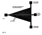
低剪断応力濾過装置の模式図を図3に示す。装置は、拡散器の中へ通じる一つの注入口チャネルを有するが、これはチャネルの広がった部分である。ある構造においては、チャネルはV字形に広がっている。拡散器は、白血球集団を濃縮しながら、血液からより小さな赤血球および血小板を濾過するように成形された細孔を有する、二つの篩を含む。拡散器の形状が、層流の流線を広げ、装置の中を移動しながらより多くの細胞が篩に接触するようにさせる(図4)。装置は、例えば赤血球および血小板のような篩を通過する細胞を回収する二つの流出口、ならびに濃縮された白血球を回収する一つの流出口という、三つの流出口を含む。
A schematic diagram of a diffuser low shear stress filtration device is shown in FIG. The device has one inlet channel that leads into the diffuser, which is an expanded portion of the channel. In some structures, the channel extends in a V shape. The diffuser includes two sieves having pores shaped to filter smaller red blood cells and platelets from the blood while concentrating the white blood cell population. The shape of the diffuser widens the laminar streamlines and allows more cells to contact the sieve as it moves through the device (Figure 4). The apparatus includes three outlets: two outlets that collect cells that pass through a sieve, such as red blood cells and platelets, and one outlet that collects concentrated white blood cells.
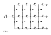
図3の装置の長さに対する、個々の篩全体にわたる圧力差を、簡単な抵抗モデルを用いて模式化した(図5)。このモデルにおいては、圧力差は篩に沿って直線的に低下し、かつ、篩の端部に向かって陰圧の損失が存在し、これは、潜在的に分離収率を低下させる、篩を通じた逆流を生じうる(図6)。従って、図3の装置の構造により、所望の状況下で作動する篩の比率の低下がもたらされる。小さな圧力損失またはそれどころか陰圧の損失を有する篩の後ろの部分よりも、篩の最初の部分により、細胞は極めて大きな圧力損失を被る。篩全体にわたるより均一な圧力損失を確実にするために、同じ抵抗モデル(図7)を用いて拡散器の形状を変更することによって、篩に沿った圧力損失におけるこの差に対処できる。篩に沿って一定の圧力損失をもたらす構造を、図8に示す。 The pressure difference across individual sieves versus the length of the device in FIG. 3 was modeled using a simple resistance model (FIG. 5). In this model, the pressure difference decreases linearly along the sieve, and there is a negative pressure loss towards the edge of the sieve, which potentially reduces the separation yield, through the sieve. Can cause backflow (Figure 6). Thus, the structure of the apparatus of FIG. 3 results in a reduction in the proportion of sieves that operate under the desired conditions. With the first part of the sieve, the cells suffer a much greater pressure drop than the part behind the sieve with a small or even negative pressure loss. To ensure a more uniform pressure drop across the sieve, this difference in pressure drop along the sieve can be addressed by changing the shape of the diffuser using the same resistance model (Figure 7). A structure that provides a constant pressure loss along the sieve is shown in FIG.
本拡散装置は、通常、赤血球および血小板の100%枯渇を保証するものではない。しかしながら、初期の赤血球/白血球比である600:1を、およそ1:1の比まで改善できる。本装置の利点とは、流速が十分に低いので、細胞にかかる剪断応力が白血球の形質または生存率に影響しない点、および、白血球の損失を最小限または皆無にするように、全ての白血球が保持されることを、フィルターが保証する点である。拡散器の角度の拡大により、より大きな濃縮因子がもたらされると考えられる。 This diffusion device usually does not guarantee 100% depletion of red blood cells and platelets. However, the initial red blood cell / white blood cell ratio of 600: 1 can be improved to a ratio of approximately 1: 1. The advantage of this device is that the flow rate is sufficiently low so that the shear stress on the cells does not affect the trait or viability of the leukocytes, and that all leukocytes are It is the point that the filter guarantees that it will be retained. It is believed that the expansion of the diffuser angle results in a greater concentration factor.
一つの拡散器からの流出口が二番目の拡散器の注入口へ注がれている拡散器を、二つ以上連続配置することによってもまた、より良い濃縮を得ることができる。柱間の隙間の拡大により、篩の中のより大きな細孔を通って白血球を失う危険性を伴う枯渇プロセスが、迅速になりうる。 Better concentration can also be obtained by arranging two or more diffusers in which the outlet from one diffuser is poured into the inlet of the second diffuser. The widening of the gaps between the columns can speed up the depletion process with the risk of losing white blood cells through larger pores in the sieve.
電気泳動:
電気泳動は、二つの電極の間にDC電圧を加えることにより、荷電した粒子を操作することを必要とする。荷電した粒子は、逆荷電した電極に向かって移動する傾向がある。細胞は、通常、正常のpH水準においては負に荷電しており、電気泳動の間は、陽極に向かって遊走する[7]。チャネル幅方向の電気泳動を用いて、粒子を流線の外へ追い出して篩と接触させることができ、一方で、チャネルに沿った流れを維持して、連続的な流れの分離を達成し、かつ、篩の目詰まりを回避することができる。通常、血液細胞は1 V/cmの加電圧で約1 μm/secの速度で移動するが、これは、合理的な時間の範囲内で、細胞などの粒子を、チャネル幅方向に移動させるのに十分である。この電圧水準はまた、気泡形成、または細胞に対する悪影響を回避する。
Electrophoresis:
Electrophoresis involves manipulating charged particles by applying a DC voltage between two electrodes. Charged particles tend to move towards the oppositely charged electrode. Cells are usually negatively charged at normal pH levels and migrate towards the anode during electrophoresis [7]. Using channel width electrophoresis, particles can be driven out of the streamline and brought into contact with the sieve while maintaining flow along the channel to achieve continuous flow separation, Moreover, clogging of the sieve can be avoided. Normally, blood cells move at a speed of about 1 μm / sec with an applied voltage of 1 V / cm. This is because particles such as cells move in the channel width direction within a reasonable time range. Enough. This voltage level also avoids bubble formation or adverse effects on the cells.
電気泳動装置の模式図を図9に示す。本装置内においては、篩は二つの電極の間に位置する。DC電圧が電極に加えられる場合、負に荷電した細胞は篩へ導かれるが、赤血球および血小板しか、篩を通過することができない。 A schematic diagram of the electrophoresis apparatus is shown in FIG. Within the device, the sieve is located between the two electrodes. When DC voltage is applied to the electrode, negatively charged cells are directed to the sieve, but only red blood cells and platelets can pass through the sieve.
誘電泳動:
誘電泳動は、例えば細胞のような粒子を操作するための、高周波における非対称のAC電場の応用である。培地および細胞の極性に応じて、細胞は正の(高電場に向かう方向)または負の(高電場から離れる方向)誘電泳動のいずれかを受ける[8,9]。異なる方向(正または負の誘電泳動)への異なる細胞の挙動は、周波数を変動させることによって、変化させることができる。赤血球は、より低い周波数においては、負の誘電泳動を受け、より高い周波数においては、正の誘電泳動を受けることが、これまでに示されている[10]。誘電泳動はまた、異なる細胞を異なる方向で、層流線を横断させて分離を引き起こすため、または連続的な流れを維持しながら篩に接触させるために、用いることができる。
Dielectrophoresis:
Dielectrophoresis is an application of an asymmetrical AC electric field at high frequencies to manipulate particles such as cells. Depending on the media and cell polarity, cells undergo either positive (direction towards high electric field) or negative (direction away from high electric field) dielectrophoresis [8,9]. The behavior of different cells in different directions (positive or negative dielectrophoresis) can be changed by varying the frequency. It has previously been shown that red blood cells undergo negative dielectrophoresis at lower frequencies and positive dielectrophoresis at higher frequencies [10]. Dielectrophoresis can also be used to cause different cells to traverse laminar flow lines in different directions to cause separation, or to contact a sieve while maintaining continuous flow.
白血球、赤血球、および血小板、または、赤血球および血小板のみを篩に向かって移動させるのに、誘電泳動を用いることができる。誘電泳動を用いた細胞の分離の模式図を図10に示す。篩を二つの電極の間に配置することによって、サイズ、形、または変形能に基づいた粒子の分離が生じる。 Dielectrophoresis can be used to move white blood cells, red blood cells, and platelets, or only red blood cells and platelets, toward the sieve. A schematic diagram of cell separation using dielectrophoresis is shown in FIG. Placing a sieve between the two electrodes results in separation of particles based on size, shape, or deformability.
別の態様において、誘電泳動を用いて、二つまたはそれ以上の細胞集団を、篩を使用することなく、空間的に分離させうる。二つの細胞集団は、その後、異なる流出口へ導かれて回収されうる。 In another embodiment, dielectrophoresis can be used to spatially separate two or more cell populations without using a sieve. The two cell populations can then be directed to different outlets and collected.
遠心力に基づいた分離:
異なる質量(サイズ)の細胞を分離するのに用いることができるもうひとつの技術とは、湾曲チャネルに作用する遠心力の使用である。粒子に作用する遠心力は、F=mω2Xにより得られる。式中、mは粒子の大きさであり、ωは、回転ローターの角速度(ラジアン/秒)であり、Xは、回転軸からの粒子の距離(またはローターの半径)である。質量および流れの速度が増加するほど、粒子に作用する遠心力もまた増加する。図11に示すようならせん構造を設計することにより、および、例えば外付けのシリンジポンプを用いて流速(粒子のスピード)を制御することにより、チャネルを分割する篩を用いて濾過される、より小さな粒子と、異なるサイズの粒子とを分離することができる。血液試料中では、より小さな赤血球および血小板は篩を通過し、かつ、より大きな白血球は通過しないので、白血球の分離および濃縮が達成される。
Separation based on centrifugal force:
Another technique that can be used to separate cells of different mass (size) is the use of centrifugal force acting on the curved channel. The centrifugal force acting on the particles is obtained by F = mω 2 X. Where m is the particle size, ω is the angular velocity (radians / second) of the rotating rotor, and X is the particle distance (or rotor radius) from the axis of rotation. As the mass and flow velocity increase, the centrifugal force acting on the particles also increases. Filtered with a sieve that divides the channel by designing a helical structure as shown in FIG. 11 and by controlling the flow rate (particle speed) using, for example, an external syringe pump, and more Small particles and particles of different sizes can be separated. In blood samples, smaller red blood cells and platelets pass through the sieve and larger white blood cells do not pass, so that separation and concentration of white blood cells is achieved.
二方向(bi-directional)流れ:
粒子の分離のためのもうひとつの技術とは、例えば外付けのシリンジポンプによって制御することができる、方向性をもつ流れの使用である。原理を、図12において説明する。試料の初期流れは、注入口1から流出口1までであり、ここで、試料が篩を通過し、より大きな粒子は排除される。全試料容量が濾過された後、排除された粒子を篩から洗い流すために緩衝液(注入口2)が用いられるが、これは流出口2を通して回収される。
Bi-directional flow:
Another technique for particle separation is the use of directional flow that can be controlled, for example, by an external syringe pump. The principle is illustrated in FIG. The initial flow of sample is from
変動性
本発明の装置は、二つを上回る粒子集団を作出するために、二つを上回る流出口および一つを上回る篩を含むように設計されうる。そのような複数の経路を、直列または並列に配列してもよい。例えば電気泳動装置においては、複数個のチャンバーを作出するために、複数の篩を電極間に配置することができる。注入口に最も近い篩が最大径の細孔を有し、かつ、一連の篩のそれぞれがより小さい細孔を有し、集団を複数の画分に分離する。誘電泳動、圧力駆動性流れ、および遠心力流れを用いた類似の装置が可能である。
Variability The device of the present invention can be designed to include more than two outlets and more than one sieve to produce more than two particle populations. Such a plurality of paths may be arranged in series or in parallel. For example, in an electrophoresis apparatus, a plurality of sieves can be arranged between the electrodes in order to create a plurality of chambers. The sieve closest to the inlet has the largest pores, and each of the series of sieves has smaller pores, separating the population into multiple fractions. Similar devices using dielectrophoresis, pressure driven flow, and centrifugal flow are possible.
加工
本発明の装置のチャネルおよび篩の加工のために、ポリ(ジメチルシロキサン)(PDMS)ソフトリソグラフィー、重合体鋳造(例えば、エポキシ、アクリル樹脂、またはウレタンを使用)、注入成形、重合体加熱エンボス加工、レーザー微細機械加工(micromachining)、薄膜表面微細機械加工、ガラスおよびシリコンの両方のディープエッチング(deep etching)、電鋳法、ならびにステレオリソグラフィー(stereolithography)などの3-D加工技術のような簡単な微細加工技術を、用いることができる。電極は、リフトオフ(lift off)、蒸着、成形、または他の析出技術のような標準技術によって加工されうる。上記で列挙された工程の大部分は、微細な外装(feature)を複製するために、フォトマスクを用いる。5μmを上回る外装サイズについては、透明素材の乳剤マスクを用いることができる。2μmから5μmの間の外装サイズは、ガラス素材のクロムフォトマスクが必要でありうる。より小さな外装に関しては、ガラス素材の電子ビーム直接描画マスク(E-beam direct write mask)を用いることができる。次に、シリコンもしくはガラスの場合には、エッチングのためのフォトレジストのパターンを明確にするために、または、例えばSU-8フォトレジストを用いて陰画複製(negative replica)を明確にするためにマスクが用いられ、その後、これを、PDMS、エポキシ、およびアクリル樹脂のような重合材料の複製成形のための原版として用いることができる。その後、加工されたチャネルを、ガラスのような硬い基材の上に接着し、装置を完成させることができる。加工のための他の方法は、当技術分野において公知である。本発明の装置は、単独の材料から、または組み合わされた材料から加工されうる。
Processing Poly (dimethylsiloxane) (PDMS) soft lithography, polymer casting (eg, using epoxy, acrylic resin, or urethane), injection molding, polymer heat embossing for processing channels and sieves of the device of the present invention Simple, such as 3-D processing techniques such as machining, laser micromachining, thin film surface micromachining, deep etching of both glass and silicon, electroforming, and stereolithography Simple microfabrication techniques can be used. The electrode can be processed by standard techniques such as lift off, vapor deposition, molding, or other deposition techniques. Most of the processes listed above use a photomask to replicate the fine features. For exterior sizes exceeding 5 μm, a transparent emulsion mask can be used. For exterior sizes between 2 μm and 5 μm, a glass chrome photomask may be required. For smaller exteriors, a glass-based E-beam direct write mask can be used. Next, in the case of silicon or glass, masks are used to clarify the pattern of the photoresist for etching, or to define negative replicas using, for example, SU-8 photoresist. Can then be used as a master for replicating polymeric materials such as PDMS, epoxies, and acrylics. The processed channel can then be glued onto a hard substrate such as glass to complete the device. Other methods for processing are known in the art. The devices of the present invention can be fabricated from single materials or from combined materials.
方法
本発明の装置を、混合物または懸濁物中の粒子集団を分離または濃縮するための方法において利用できる。好ましくは、本発明の方法により、望ましくない粒子のうち、少なくとも50%、60%、70%、80%、90%、95%または99%が、試料から除去される。本発明の方法においては、試料は、本発明の装置の中に導入される。装置の中に導入されると、篩を通過することによって、または篩を通過しないことによって、所望の細胞が大量の試料から分離される。細胞は、例えば圧力駆動性流れ、電場、または遠心力によって発生させた外からの力によって、篩に向かう方向に(または篩から離れる方向に)導かれる。本発明の装置は少なくとも二つの流出口を有し、ここで、一つの流出口へ到達するためには、細胞は篩を通過しなければならない。分離されると、例えばさらなる精製、解析、貯蔵、改良、または培養のために、粒子が回収されうる。
Methods The devices of the present invention can be utilized in methods for separating or concentrating particle populations in mixtures or suspensions. Preferably, the method of the present invention removes at least 50%, 60%, 70%, 80%, 90%, 95% or 99% of the unwanted particles from the sample. In the method of the present invention, a sample is introduced into the device of the present invention. Once introduced into the device, the desired cells are separated from the bulk sample by passing through a sieve or not through a sieve. The cells are guided in the direction towards (or away from) the sieve, for example by external forces generated by pressure-driven flow, electric fields, or centrifugal forces. The device of the present invention has at least two outlets, where the cells must pass through a sieve to reach one outlet. Once separated, the particles can be recovered, for example, for further purification, analysis, storage, improvement, or culture.
血液から白血球を分離することが有用であると一般的には記載されるが、本発明の方法を用いて他の細胞または粒子を分離してもよい。例えば、尿または髄液など正常では無菌の体液から細胞を単離するために、本装置を用いてもよい。他の態様においては、例えば、母体血由来の胎児赤血球、血液または他の体液由来の癌細胞、および動物または環境試料由来の感染性微生物のような希少な細胞を、試料から単離することができる。本発明の装置は、従って、医療診断、環境もしくは品質保証試験、コンビナトリアルケミストリー、または基礎研究の分野において使用されうる。 Although it is generally described that separating leukocytes from blood is useful, other cells or particles may be separated using the methods of the present invention. For example, the device may be used to isolate cells from normally sterile body fluids such as urine or spinal fluid. In other embodiments, rare cells such as fetal erythrocytes from maternal blood, cancer cells from blood or other body fluids, and infectious microorganisms from animal or environmental samples may be isolated from the sample. it can. The device according to the invention can therefore be used in the fields of medical diagnosis, environmental or quality assurance testing, combinatorial chemistry, or basic research.
次の実施例は、本発明の様々な特徴を説明することを意図するものであって、決して限定することを意図しない。 The following examples are intended to illustrate various features of the present invention and are not intended to be limiting in any way.
実施例1. 拡散フィルター:
より小さな赤血球および血小板を、より大きな白血球から、サイズに基づいて分離するための装置が、簡単なソフトリソグラフィー技術を用いて、加工された(図13)。装置の外装と形状を有するクロムフォトマスクを加工して、シリコンウエハー(silicon wafer)を、SU-8フォトレジスト中の装置の陰画複製でパターン付けるのに用いた。その後この原版は、標準的な複製成形技術を用いて、PDMSチャネルおよび篩構造を加工するのに用いられた。PDMS装置を、酸素プラズマで処理後、スライドガラスに接着した。図13は、拡散器の形状および篩と共に、チャネル構造の低倍率画像を示している。装置を流れる粒子または細胞の大部分を確実に篩と相互作用させるために層流の流線を広げるのに、拡散器の形状が用いられる。より小さな赤血球および血小板は篩を通過し、かつ、より大きな白血球は中央のチャネルに閉じこめられる。篩の、より高倍率の写真を図14に示す。
Example 1. Diffusion filter:
A device for separating smaller red blood cells and platelets from larger white blood cells based on size was processed using simple soft lithography techniques (FIG. 13). A chrome photomask with the device exterior and shape was processed and used to pattern a silicon wafer with a negative copy of the device in SU-8 photoresist. This master was then used to fabricate PDMS channels and sieve structures using standard replication techniques. The PDMS device was bonded to a glass slide after being treated with oxygen plasma. FIG. 13 shows a low magnification image of the channel structure along with the diffuser shape and sieve. The shape of the diffuser is used to widen the laminar streamlines to ensure that most of the particles or cells flowing through the device interact with the sieve. Smaller red blood cells and platelets pass through the sieve, and larger white blood cells are confined to the central channel. A higher magnification photograph of the sieve is shown in FIG.
実施例2. 電気泳動:
電気移動はまた、細胞がその層流の流線を横断するため、および、全ての細胞または粒子が篩と相互作用するまたは接触することを確実にするために、用いることができる。本装置は実施例1のようにして加工されたが、PDMSは、フォトリソグラフィーでパターン付けされた金電極を有するスライドガラスに接着される(図15)。負に荷電した細胞を、正に荷電した電極へと引きつけるために、電気泳動が用いられる。より小さな赤血球および血小板は篩を通過するが、一方、より大きな白血球は排除される。白血球は分離ポートを通して、単離されて抽出される。
Example 2. Electrophoresis:
Electrotransfer can also be used to allow cells to cross their laminar streamlines and to ensure that all cells or particles interact with or come in contact with the sieve. The device was processed as in Example 1, but PDMS is bonded to a glass slide having gold electrodes patterned by photolithography (FIG. 15). Electrophoresis is used to attract negatively charged cells to positively charged electrodes. Smaller red blood cells and platelets pass through the sieve, while larger white blood cells are excluded. White blood cells are isolated and extracted through a separation port.
参照文献
他の態様
上記の明細書中に記載された全ての刊行物、特許、および特許出願は、参照によって本明細書に組み込まれる。記載された本発明の方法およびシステムの様々な修正および改変は、本発明の範囲および精神から逸脱することなく、当業者にとって明白であろう。本発明は、具体的な態様に関連して記載されているが、請求された本発明は、そのような具体的態様に過度に制限されてはならないことが、理解されるべきである。実際に、当業者にとって明らかな、本発明を実行するために記載された様式の様々な修正は、本発明の範囲内であることが意図されている。
Other Embodiments All publications, patents, and patent applications mentioned in the above specification are herein incorporated by reference. Various modifications and variations of the described methods and system of the invention will be apparent to those skilled in the art without departing from the scope and spirit of the invention. Although the invention has been described in connection with specific embodiments, it is to be understood that the claimed invention should not be unduly limited to such specific embodiments. Indeed, various modifications of the described modes for carrying out the invention which are obvious to those skilled in the art are intended to be within the scope of the present invention.
他の態様は添付の特許請求の範囲に記載されている。 Other aspects are set forth in the appended claims.
Claims (21)
b. 注入口と第二流出口の間には配置されず、注入口と第一流出口の間に配置される、第一篩;ならびに
c. 粒子を第一篩へ導く、力発生装置
を含む、粒子の濃度を高めるための装置。 a channel having an inlet and a first outlet and a second outlet;
b. a first sieve not disposed between the inlet and the second outlet, but disposed between the inlet and the first outlet; and
c. A device for increasing the concentration of particles, including a force generator, which directs the particles to the first sieve.
a. i. 注入口および第一流出口および第二流出口を有するチャネル;
ii. 注入口と第二流出口の間には配置されず、注入口と第一流出口の間に配置される、第一篩;ならびに
iii. 粒子を第一篩へ導くための力発生装置
を含む装置を供給する段階;
b. 粒子含有流体を、注入口を通ってチャネル内へ導く段階;
c. 流体中の粒子が第一篩へ導かれ、かつ、粒子のサイズ、形、または変形能に基づいて第一篩を実質的に通過するまたは通過しないように、力発生装置を作動させる段階;ならびに
d. 標的集団の粒子が第一篩を実質的に通過する場合には第一流出口から、または、標的集団の粒子が第一篩を実質的に通過しない場合には第二流出口から、標的集団の粒子を含む硫出物を回収し、それにより、粒子の標的集団中で濃縮された試料を産生する段階。 A method of producing a sample enriched in a target population of particles from a particle-containing fluid comprising the following steps:
ai a channel having an inlet and a first outlet and a second outlet;
ii. a first sieve not disposed between the inlet and the second outlet, but disposed between the inlet and the first outlet; and
iii. providing a device including a force generator for directing the particles to the first sieve;
b. directing the particle-containing fluid through the inlet into the channel;
c. actuating the force generator such that particles in the fluid are directed to the first sieve and substantially pass or do not pass through the first sieve based on the size, shape, or deformability of the particles; And
d. from the first outlet if the particles of the target population substantially pass through the first sieve, or from the second outlet if the particles of the target population do not substantially pass through the first sieve. Recovering the leachate containing the particles of the population, thereby producing a sample enriched in the target population of particles.
Applications Claiming Priority (2)
| Application Number | Priority Date | Filing Date | Title |
|---|---|---|---|
| US47829903P | 2003-06-13 | 2003-06-13 | |
| PCT/US2004/018373 WO2004113877A1 (en) | 2003-06-13 | 2004-06-09 | Microfluidic systems for size based removal of red blood cells and platelets from blood |
Publications (2)
| Publication Number | Publication Date |
|---|---|
| JP2007503597A true JP2007503597A (en) | 2007-02-22 |
| JP2007503597A5 JP2007503597A5 (en) | 2007-07-05 |
Family
ID=33539083
Family Applications (1)
| Application Number | Title | Priority Date | Filing Date |
|---|---|---|---|
| JP2006533661A Pending JP2007503597A (en) | 2003-06-13 | 2004-06-09 | Microfluidic system for removing red blood cells and platelets from blood based on size |
Country Status (6)
| Country | Link |
|---|---|
| US (1) | US20070160503A1 (en) |
| EP (1) | EP1636564A1 (en) |
| JP (1) | JP2007503597A (en) |
| AU (1) | AU2004250131A1 (en) |
| CA (1) | CA2529285A1 (en) |
| WO (1) | WO2004113877A1 (en) |
Cited By (1)
| Publication number | Priority date | Publication date | Assignee | Title |
|---|---|---|---|---|
| JP2016515712A (en) * | 2013-04-15 | 2016-05-30 | ベクトン・ディキンソン・アンド・カンパニーBecton, Dickinson And Company | Biological fluid separation device and biological fluid separation and inspection system |
Families Citing this family (110)
| Publication number | Priority date | Publication date | Assignee | Title |
|---|---|---|---|---|
| US6913697B2 (en) | 2001-02-14 | 2005-07-05 | Science & Technology Corporation @ Unm | Nanostructured separation and analysis devices for biological membranes |
| JP2006501449A (en) | 2002-09-27 | 2006-01-12 | ザ ジェネラル ホスピタル コーポレーション | Microfluidic device for cell separation and use thereof |
| JP2006058195A (en) * | 2004-08-23 | 2006-03-02 | Alps Electric Co Ltd | Inspection plate and inspection method using same |
| US20070196820A1 (en) | 2005-04-05 | 2007-08-23 | Ravi Kapur | Devices and methods for enrichment and alteration of cells and other particles |
| US20070026418A1 (en) * | 2005-07-29 | 2007-02-01 | Martin Fuchs | Devices and methods for enrichment and alteration of circulating tumor cells and other particles |
| EP2594631A1 (en) | 2005-04-05 | 2013-05-22 | Cellpoint Diagnostics | Devices and method for detecting circulating tumor cells and other particles |
| US20060266692A1 (en) * | 2005-05-25 | 2006-11-30 | Innovative Micro Technology | Microfabricated cross flow filter and method of manufacture |
| WO2007044091A2 (en) | 2005-06-02 | 2007-04-19 | Fluidigm Corporation | Analysis using microfluidic partitioning devices |
| US8921102B2 (en) | 2005-07-29 | 2014-12-30 | Gpb Scientific, Llc | Devices and methods for enrichment and alteration of circulating tumor cells and other particles |
| US7993821B2 (en) * | 2005-08-11 | 2011-08-09 | University Of Washington | Methods and apparatus for the isolation and enrichment of circulating tumor cells |
| US8173413B2 (en) * | 2005-08-11 | 2012-05-08 | University Of Washington | Separation and concentration of biological cells and biological particles using a one-dimensional channel |
| EP1795894A1 (en) * | 2005-12-06 | 2007-06-13 | Roche Diagnostics GmbH | Plasma separation on a disk like device |
| EP4108780A1 (en) | 2006-06-14 | 2022-12-28 | Verinata Health, Inc. | Rare cell analysis using sample splitting and dna tags |
| EP3406736B1 (en) | 2006-06-14 | 2022-09-07 | Verinata Health, Inc. | Methods for the diagnosis of fetal abnormalities |
| DK2029778T3 (en) | 2006-06-14 | 2018-08-20 | Verinata Health Inc | DIAGNOSIS OF Fetal ABNORMITIES |
| US8137912B2 (en) | 2006-06-14 | 2012-03-20 | The General Hospital Corporation | Methods for the diagnosis of fetal abnormalities |
| US20080050739A1 (en) | 2006-06-14 | 2008-02-28 | Roland Stoughton | Diagnosis of fetal abnormalities using polymorphisms including short tandem repeats |
| WO2007147018A1 (en) * | 2006-06-14 | 2007-12-21 | Cellpoint Diagnostics, Inc. | Analysis of rare cell-enriched samples |
| EP2589668A1 (en) | 2006-06-14 | 2013-05-08 | Verinata Health, Inc | Rare cell analysis using sample splitting and DNA tags |
| EP2029779A4 (en) | 2006-06-14 | 2010-01-20 | Living Microsystems Inc | Use of highly parallel snp genotyping for fetal diagnosis |
| US8931644B2 (en) | 2006-11-30 | 2015-01-13 | Palo Alto Research Center Incorporated | Method and apparatus for splitting fluid flow in a membraneless particle separation system |
| US9862624B2 (en) | 2007-11-07 | 2018-01-09 | Palo Alto Research Center Incorporated | Device and method for dynamic processing in water purification |
| US9433880B2 (en) | 2006-11-30 | 2016-09-06 | Palo Alto Research Center Incorporated | Particle separation and concentration system |
| US8276760B2 (en) | 2006-11-30 | 2012-10-02 | Palo Alto Research Center Incorporated | Serpentine structures for continuous flow particle separations |
| US9486812B2 (en) | 2006-11-30 | 2016-11-08 | Palo Alto Research Center Incorporated | Fluidic structures for membraneless particle separation |
| US10052571B2 (en) * | 2007-11-07 | 2018-08-21 | Palo Alto Research Center Incorporated | Fluidic device and method for separation of neutrally buoyant particles |
| US8841135B2 (en) * | 2007-06-20 | 2014-09-23 | University Of Washington | Biochip for high-throughput screening of circulating tumor cells |
| FR2918900A1 (en) * | 2007-07-18 | 2009-01-23 | Commissariat Energie Atomique | DEVICE AND METHOD FOR SEPARATING THE COMPONENTS OF A SUSPENSION AND PARTICULARLY BLOOD |
| US8008032B2 (en) | 2008-02-25 | 2011-08-30 | Cellective Dx Corporation | Tagged ligands for enrichment of rare analytes from a mixed sample |
| EP2952589B1 (en) | 2008-09-20 | 2018-02-14 | The Board of Trustees of The Leland Stanford Junior University | Noninvasive diagnosis of fetal aneuploidy by sequencing |
| IT1391408B1 (en) * | 2008-10-02 | 2011-12-23 | Silicon Biosystems Spa | CHAMBER OF SEPARATION |
| US20100304978A1 (en) * | 2009-01-26 | 2010-12-02 | David Xingfei Deng | Methods and compositions for identifying a fetal cell |
| WO2010087847A1 (en) * | 2009-01-30 | 2010-08-05 | Bio-Rad Laboratories, Inc. | Dielectrophoretic device with actuator |
| WO2010107399A1 (en) * | 2009-03-20 | 2010-09-23 | Agency For Science, Technology And Research | Devices for separating cells and methods of using them |
| AU2010239131A1 (en) | 2009-04-21 | 2011-11-17 | Genetic Technologies Limited | Methods for obtaining fetal genetic material |
| WO2011005757A1 (en) | 2009-07-07 | 2011-01-13 | Sony Corporation | Microfluidic device adapted for post-centrifugation use with selective sample extraction and methods for its use |
| US9034658B2 (en) | 2009-11-23 | 2015-05-19 | The General Hospital Corporation | Microfluidic devices for the capture of biological sample components |
| CN102791616B (en) | 2009-12-23 | 2015-07-29 | 西托维拉公司 | For the system and method for particulate filter |
| US20110312503A1 (en) | 2010-01-23 | 2011-12-22 | Artemis Health, Inc. | Methods of fetal abnormality detection |
| WO2011119962A2 (en) * | 2010-03-26 | 2011-09-29 | The General Hospital Corporation | Microfluidic enrichment of selected cell populations |
| ITTO20100068U1 (en) * | 2010-04-20 | 2011-10-21 | Eltek Spa | MICROFLUID AND / OR EQUIPMENT DEVICES FOR MICROFLUID DEVICES |
| WO2012016136A2 (en) | 2010-07-30 | 2012-02-02 | The General Hospital Corporation | Microscale and nanoscale structures for manipulating particles |
| EP2603793A4 (en) * | 2010-08-15 | 2014-03-19 | Gpb Scientific Llc | Microfluidic cell separation in the assay of blood |
| JP5934921B2 (en) * | 2011-04-08 | 2016-06-15 | パナソニックIpマネジメント株式会社 | Diagnostic kit and method of use thereof |
| TWI613294B (en) * | 2011-09-14 | 2018-02-01 | 臺北醫學大學 | Microfluidic chips for acquiring sperms with high motility, productions and applications thereof |
| CA2850412A1 (en) * | 2011-09-30 | 2013-04-04 | The University Of British Columbia | Methods and apparatus for flow-controlled wetting |
| WO2013177206A2 (en) | 2012-05-21 | 2013-11-28 | Fluidigm Corporation | Single-particle analysis of particle populations |
| US10323279B2 (en) | 2012-08-14 | 2019-06-18 | 10X Genomics, Inc. | Methods and systems for processing polynucleotides |
| CA2881685C (en) | 2012-08-14 | 2023-12-05 | 10X Genomics, Inc. | Microcapsule compositions and methods |
| US9951386B2 (en) | 2014-06-26 | 2018-04-24 | 10X Genomics, Inc. | Methods and systems for processing polynucleotides |
| US9567631B2 (en) | 2012-12-14 | 2017-02-14 | 10X Genomics, Inc. | Methods and systems for processing polynucleotides |
| US10273541B2 (en) | 2012-08-14 | 2019-04-30 | 10X Genomics, Inc. | Methods and systems for processing polynucleotides |
| US10221442B2 (en) | 2012-08-14 | 2019-03-05 | 10X Genomics, Inc. | Compositions and methods for sample processing |
| US9701998B2 (en) | 2012-12-14 | 2017-07-11 | 10X Genomics, Inc. | Methods and systems for processing polynucleotides |
| US9388465B2 (en) | 2013-02-08 | 2016-07-12 | 10X Genomics, Inc. | Polynucleotide barcode generation |
| US10584381B2 (en) | 2012-08-14 | 2020-03-10 | 10X Genomics, Inc. | Methods and systems for processing polynucleotides |
| US11591637B2 (en) | 2012-08-14 | 2023-02-28 | 10X Genomics, Inc. | Compositions and methods for sample processing |
| US10752949B2 (en) | 2012-08-14 | 2020-08-25 | 10X Genomics, Inc. | Methods and systems for processing polynucleotides |
| US10533221B2 (en) | 2012-12-14 | 2020-01-14 | 10X Genomics, Inc. | Methods and systems for processing polynucleotides |
| US20150064153A1 (en) | 2013-03-15 | 2015-03-05 | The Trustees Of Princeton University | High efficiency microfluidic purification of stem cells to improve transplants |
| CN105264127B (en) | 2013-03-15 | 2019-04-09 | Gpb科学有限责任公司 | The on piece microfluidic process of particle |
| EP2971279B1 (en) | 2013-03-15 | 2019-11-13 | The Trustees of Princeton University | Methods and devices for high throughput purification |
| WO2014172234A1 (en) | 2013-04-15 | 2014-10-23 | Becton, Dickinson And Company | Biological fluid collection device and biological fluid separation and testing system |
| EP2986221B1 (en) | 2013-04-15 | 2019-02-27 | Becton, Dickinson and Company | Biological fluid sampling device |
| EP2986218B1 (en) | 2013-04-15 | 2017-12-20 | Becton, Dickinson and Company | Biological fluid collection device and biological fluid separation and testing system |
| US9549700B2 (en) | 2013-04-15 | 2017-01-24 | Becton, Dickinson And Company | Biological fluid sampling transfer device and biological fluid separation and testing system |
| WO2014172242A1 (en) | 2013-04-15 | 2014-10-23 | Becton, Dickinson And Company | Blood sampling transfer device and blood separation and testing system |
| BR112015026159B1 (en) | 2013-04-15 | 2022-10-25 | Becton, Dickinson And Company | BLOOD COLLECTION TRANSFER DEVICE, BLOOD COLLECTION SYSTEM AND BLOOD SEPARATION SYSTEM |
| WO2014172244A1 (en) | 2013-04-15 | 2014-10-23 | Becton, Dickinson And Company | Biological fluid separation device and biological fluid separation and testing system |
| MX2015014478A (en) | 2013-04-15 | 2016-02-05 | Becton Dickinson Co | Biological fluid transfer device and biological fluid sampling system. |
| WO2014172239A1 (en) | 2013-04-15 | 2014-10-23 | Becton, Dickinson And Company | Biological fluid collection device and biological fluid separation and testing system |
| JP6193474B2 (en) | 2013-04-15 | 2017-09-06 | ベクトン・ディキンソン・アンド・カンパニーBecton, Dickinson And Company | Biological fluid collection and transfer device and biological fluid separation and inspection system |
| US10238325B2 (en) | 2013-04-15 | 2019-03-26 | Becton, Dickinson And Company | Medical device for collection of a biological sample |
| CA2909363C (en) | 2013-04-15 | 2017-06-13 | Becton, Dickinson And Company | Biological fluid collection device and biological fluid collection and testing system |
| ES2755490T3 (en) * | 2013-04-15 | 2020-04-22 | Becton Dickinson Co | Biological Fluid Extraction Device and Biological Fluid Separation System |
| CA2937484C (en) | 2014-01-20 | 2023-09-19 | Halcyon Biomedical, Incorporated | Separation and concentration of particles |
| AU2015243445B2 (en) | 2014-04-10 | 2020-05-28 | 10X Genomics, Inc. | Fluidic devices, systems, and methods for encapsulating and partitioning reagents, and applications of same |
| EP4053292A1 (en) | 2014-06-26 | 2022-09-07 | 10X Genomics, Inc. | Methods of analyzing nucleic acids from individual cells or cell populations |
| WO2016069939A1 (en) | 2014-10-29 | 2016-05-06 | 10X Genomics, Inc. | Methods and compositions for targeted nucleic acid sequencing |
| US9975122B2 (en) | 2014-11-05 | 2018-05-22 | 10X Genomics, Inc. | Instrument systems for integrated sample processing |
| CA2972969A1 (en) | 2015-01-12 | 2016-07-21 | 10X Genomics, Inc. | Processes and systems for preparing nucleic acid sequencing libraries and libraries prepared using same |
| GB2534182A (en) * | 2015-01-15 | 2016-07-20 | Univ Dublin City | Microfluidic device |
| US20180015470A1 (en) * | 2015-01-23 | 2018-01-18 | Unimed Biotech (Shanghai) Co., Ltd. | Microfluidics based fetal cell detection and isolation for non-invasive prenatal testing |
| EP3262407B1 (en) | 2015-02-24 | 2023-08-30 | 10X Genomics, Inc. | Partition processing methods and systems |
| WO2016138148A1 (en) | 2015-02-24 | 2016-09-01 | 10X Genomics, Inc. | Methods for targeted nucleic acid sequence coverage |
| CN107580627A (en) * | 2015-05-18 | 2018-01-12 | 10X基因组学有限公司 | For the flowing solid compositions in biochemical reaction and analysis |
| CN107771057B (en) | 2015-08-06 | 2021-03-09 | 贝克顿·迪金森公司 | Biological fluid collection device and biological fluid collection system |
| US10976232B2 (en) | 2015-08-24 | 2021-04-13 | Gpb Scientific, Inc. | Methods and devices for multi-step cell purification and concentration |
| CN105203375B (en) * | 2015-09-16 | 2018-05-22 | 北京大学 | A kind of plasma separator part of high throughput and preparation method thereof |
| CN115369161A (en) | 2015-12-04 | 2022-11-22 | 10X 基因组学有限公司 | Methods and compositions for nucleic acid analysis |
| CN105675460A (en) * | 2016-03-08 | 2016-06-15 | 重庆理工大学 | Method for accelerating blood sedimentation by virtue of voltage |
| EP3244208A1 (en) * | 2016-05-09 | 2017-11-15 | Sumitomo Rubber Industries, Ltd. | Medical analysis device and cell analysis method |
| WO2017197338A1 (en) | 2016-05-13 | 2017-11-16 | 10X Genomics, Inc. | Microfluidic systems and methods of use |
| GB201617723D0 (en) | 2016-10-19 | 2016-11-30 | Univ London Queen Mary | Method for predicting prostate cancer metastasis |
| GB201617722D0 (en) | 2016-10-19 | 2016-11-30 | Univ London Queen Mary | Method for determining prognosis of cancer |
| US10550429B2 (en) | 2016-12-22 | 2020-02-04 | 10X Genomics, Inc. | Methods and systems for processing polynucleotides |
| US10815525B2 (en) | 2016-12-22 | 2020-10-27 | 10X Genomics, Inc. | Methods and systems for processing polynucleotides |
| US10011872B1 (en) | 2016-12-22 | 2018-07-03 | 10X Genomics, Inc. | Methods and systems for processing polynucleotides |
| EP4029939B1 (en) | 2017-01-30 | 2023-06-28 | 10X Genomics, Inc. | Methods and systems for droplet-based single cell barcoding |
| SG11201901822QA (en) | 2017-05-26 | 2019-03-28 | 10X Genomics Inc | Single cell analysis of transposase accessible chromatin |
| US20180340169A1 (en) | 2017-05-26 | 2018-11-29 | 10X Genomics, Inc. | Single cell analysis of transposase accessible chromatin |
| AU2018323875A1 (en) | 2017-09-01 | 2020-04-23 | Gpb Scientific, Inc. | Methods for preparing therapeutically active cells using microfluidics |
| SG11201913654QA (en) | 2017-11-15 | 2020-01-30 | 10X Genomics Inc | Functionalized gel beads |
| US10829815B2 (en) | 2017-11-17 | 2020-11-10 | 10X Genomics, Inc. | Methods and systems for associating physical and genetic properties of biological particles |
| EP3775271A1 (en) | 2018-04-06 | 2021-02-17 | 10X Genomics, Inc. | Systems and methods for quality control in single cell processing |
| CN111215157B (en) * | 2018-11-26 | 2021-12-24 | 南京怡天生物科技有限公司 | Microfluidic chip, device containing same and sample concentration method |
| WO2021011907A1 (en) | 2019-07-18 | 2021-01-21 | Gpb Scientific, Inc. | Ordered processing of blood products to produce therapeutically active cells |
| CN110606373A (en) * | 2019-09-29 | 2019-12-24 | 中国石油大学(北京) | Wear-resistant electrostatic method and electrostatic adjusting device for elbow of pneumatic conveying system |
| AU2020411478A1 (en) | 2019-12-28 | 2022-07-14 | Gpb Scientific, Inc. | Microfluidic cartridges for processing particles and cells |
| US11821828B1 (en) * | 2022-12-20 | 2023-11-21 | Kuwait University | System and method for determining physical stability of dispersed particles in flowing liquid suspensions |
Family Cites Families (96)
| Publication number | Priority date | Publication date | Assignee | Title |
|---|---|---|---|---|
| US4009435A (en) * | 1973-10-19 | 1977-02-22 | Coulter Electronics, Inc. | Apparatus for preservation and identification of particles analyzed by flow-through apparatus |
| US4190535A (en) * | 1978-02-27 | 1980-02-26 | Corning Glass Works | Means for separating lymphocytes and monocytes from anticoagulated blood |
| US4434156A (en) * | 1981-10-26 | 1984-02-28 | The Salk Institute For Biological Studies | Monoclonal antibodies specific for the human transferrin receptor glycoprotein |
| IL68507A (en) * | 1982-05-10 | 1986-01-31 | Univ Bar Ilan | System and methods for cell selection |
| US4999283A (en) * | 1986-01-10 | 1991-03-12 | University Of Kentucky Research Foundation | Method for x and y spermatozoa separation |
| US4800159A (en) * | 1986-02-07 | 1989-01-24 | Cetus Corporation | Process for amplifying, detecting, and/or cloning nucleic acid sequences |
| US4906439A (en) * | 1986-03-25 | 1990-03-06 | Pb Diagnostic Systems, Inc. | Biological diagnostic device and method of use |
| US4814098A (en) * | 1986-09-06 | 1989-03-21 | Bellex Corporation | Magnetic material-physiologically active substance conjugate |
| JP2662215B2 (en) * | 1986-11-19 | 1997-10-08 | 株式会社日立製作所 | Cell holding device |
| JP2559760B2 (en) * | 1987-08-31 | 1996-12-04 | 株式会社日立製作所 | Cell delivery method |
| EP0440749B1 (en) * | 1988-08-31 | 1997-05-28 | Aprogenex, Inc. | Manual in situ hybridization assay |
| US5183744A (en) * | 1988-10-26 | 1993-02-02 | Hitachi, Ltd. | Cell handling method for cell fusion processor |
| US4984574A (en) * | 1988-11-23 | 1991-01-15 | Seth Goldberg | Noninvasive fetal oxygen monitor using NMR |
| US5641628A (en) * | 1989-11-13 | 1997-06-24 | Children's Medical Center Corporation | Non-invasive method for isolation and detection of fetal DNA |
| US6176962B1 (en) * | 1990-02-28 | 2001-01-23 | Aclara Biosciences, Inc. | Methods for fabricating enclosed microchannel structures |
| US5858188A (en) * | 1990-02-28 | 1999-01-12 | Aclara Biosciences, Inc. | Acrylic microchannels and their use in electrophoretic applications |
| US5186827A (en) * | 1991-03-25 | 1993-02-16 | Immunicon Corporation | Apparatus for magnetic separation featuring external magnetic means |
| US5296375A (en) * | 1992-05-01 | 1994-03-22 | Trustees Of The University Of Pennsylvania | Mesoscale sperm handling devices |
| US5726026A (en) * | 1992-05-01 | 1998-03-10 | Trustees Of The University Of Pennsylvania | Mesoscale sample preparation device and systems for determination and processing of analytes |
| US5486335A (en) * | 1992-05-01 | 1996-01-23 | Trustees Of The University Of Pennsylvania | Analysis based on flow restriction |
| US5498392A (en) * | 1992-05-01 | 1996-03-12 | Trustees Of The University Of Pennsylvania | Mesoscale polynucleotide amplification device and method |
| US5637469A (en) * | 1992-05-01 | 1997-06-10 | Trustees Of The University Of Pennsylvania | Methods and apparatus for the detection of an analyte utilizing mesoscale flow systems |
| US5629147A (en) * | 1992-07-17 | 1997-05-13 | Aprogenex, Inc. | Enriching and identifying fetal cells in maternal blood for in situ hybridization |
| WO1994007138A1 (en) * | 1992-09-14 | 1994-03-31 | Fodstad Oystein | Detection of specific target cells in specialized or mixed cell population and solutions containing mixed cell populations |
| US5275933A (en) * | 1992-09-25 | 1994-01-04 | The Board Of Trustees Of The Leland Stanford Junior University | Triple gradient process for recovering nucleated fetal cells from maternal blood |
| US5489506A (en) * | 1992-10-26 | 1996-02-06 | Biolife Systems, Inc. | Dielectrophoretic cell stream sorter |
| US5714325A (en) * | 1993-09-24 | 1998-02-03 | New England Medical Center Hospitals | Prenatal diagnosis by isolation of fetal granulocytes from maternal blood |
| US6001229A (en) * | 1994-08-01 | 1999-12-14 | Lockheed Martin Energy Systems, Inc. | Apparatus and method for performing microfluidic manipulations for chemical analysis |
| US5707799A (en) * | 1994-09-30 | 1998-01-13 | Abbott Laboratories | Devices and methods utilizing arrays of structures for analyte capture |
| US5709943A (en) * | 1995-05-04 | 1998-01-20 | Minnesota Mining And Manufacturing Company | Biological adsorption supports |
| US5715946A (en) * | 1995-06-07 | 1998-02-10 | Reichenbach; Steven H. | Method and apparatus for sorting particles suspended in a fluid |
| DE69619400T2 (en) * | 1995-06-16 | 2002-09-26 | Univ Washington Seattle | FLAT MICROPRODUCED CROSS-FLOW FILTER FOR LIQUIDS |
| US5856174A (en) * | 1995-06-29 | 1999-01-05 | Affymetrix, Inc. | Integrated nucleic acid diagnostic device |
| US5863502A (en) * | 1996-01-24 | 1999-01-26 | Sarnoff Corporation | Parallel reaction cassette and associated devices |
| US6387707B1 (en) * | 1996-04-25 | 2002-05-14 | Bioarray Solutions | Array Cytometry |
| EP0920627B1 (en) * | 1996-06-07 | 2004-05-12 | Immunivest Corporation | Magnetic separation employing external and internal gradients |
| US6074827A (en) * | 1996-07-30 | 2000-06-13 | Aclara Biosciences, Inc. | Microfluidic method for nucleic acid purification and processing |
| US5858187A (en) * | 1996-09-26 | 1999-01-12 | Lockheed Martin Energy Systems, Inc. | Apparatus and method for performing electrodynamic focusing on a microchip |
| US5731156A (en) * | 1996-10-21 | 1998-03-24 | Applied Imaging, Inc. | Use of anti-embryonic hemoglobin antibodies to identify fetal cells |
| US5879624A (en) * | 1997-01-15 | 1999-03-09 | Boehringer Laboratories, Inc. | Method and apparatus for collecting and processing blood |
| US6169816B1 (en) * | 1997-05-14 | 2001-01-02 | Applied Imaging, Inc. | Identification of objects of interest using multiple illumination schemes and finding overlap of features in corresponding multiple images |
| US5869004A (en) * | 1997-06-09 | 1999-02-09 | Caliper Technologies Corp. | Methods and apparatus for in situ concentration and/or dilution of materials in microfluidic systems |
| US5882465A (en) * | 1997-06-18 | 1999-03-16 | Caliper Technologies Corp. | Method of manufacturing microfluidic devices |
| US7214298B2 (en) * | 1997-09-23 | 2007-05-08 | California Institute Of Technology | Microfabricated cell sorter |
| US5842787A (en) * | 1997-10-09 | 1998-12-01 | Caliper Technologies Corporation | Microfluidic systems incorporating varied channel dimensions |
| US5962250A (en) * | 1997-10-28 | 1999-10-05 | Glaxo Group Limited | Split multi-well plate and methods |
| US6197523B1 (en) * | 1997-11-24 | 2001-03-06 | Robert A. Levine | Method for the detection, identification, enumeration and confirmation of circulating cancer and/or hematologic progenitor cells in whole blood |
| US6537505B1 (en) * | 1998-02-20 | 2003-03-25 | Bio Dot, Inc. | Reagent dispensing valve |
| US6036857A (en) * | 1998-02-20 | 2000-03-14 | Florida State University Research Foundation, Inc. | Apparatus for continuous magnetic separation of components from a mixture |
| US6200765B1 (en) * | 1998-05-04 | 2001-03-13 | Pacific Northwest Cancer Foundation | Non-invasive methods to detect prostate cancer |
| US6529835B1 (en) * | 1998-06-25 | 2003-03-04 | Caliper Technologies Corp. | High throughput methods, systems and apparatus for performing cell based screening assays |
| FR2782730B1 (en) * | 1998-08-25 | 2002-05-17 | Biocom Sa | CELL SEPARATION PROCESS FOR THE ISOLATION OF PATHOGENIC CELLS, PARTICULARLY RARE CANCERES, EQUIPMENT AND REAGENT FOR IMPLEMENTING THE PROCESS AND APPLICATION OF THE PROCESS |
| ES2172353T3 (en) * | 1998-09-18 | 2002-09-16 | Micromet Ag | AMPLIFICATION OF THE DNA OF A SINGLE CELL. |
| CN1185492C (en) * | 1999-03-15 | 2005-01-19 | 清华大学 | Single-point strobed micro electromagnetic units array chip or electromagnetic biologic chip and application thereof |
| US6858439B1 (en) * | 1999-03-15 | 2005-02-22 | Aviva Biosciences | Compositions and methods for separation of moieties on chips |
| US6511967B1 (en) * | 1999-04-23 | 2003-01-28 | The General Hospital Corporation | Use of an internalizing transferrin receptor to image transgene expression |
| US6174683B1 (en) * | 1999-04-26 | 2001-01-16 | Biocept, Inc. | Method of making biochips and the biochips resulting therefrom |
| US6524456B1 (en) * | 1999-08-12 | 2003-02-25 | Ut-Battelle, Llc | Microfluidic devices for the controlled manipulation of small volumes |
| US6613581B1 (en) * | 1999-08-26 | 2003-09-02 | Caliper Technologies Corp. | Microfluidic analytic detection assays, devices, and integrated systems |
| EP1218547A4 (en) * | 1999-10-15 | 2005-04-20 | Ventana Med Syst Inc | Method of detecting single gene copies in-situ |
| US6692952B1 (en) * | 1999-11-10 | 2004-02-17 | Massachusetts Institute Of Technology | Cell analysis and sorting apparatus for manipulation of cells |
| US6361958B1 (en) * | 1999-11-12 | 2002-03-26 | Motorola, Inc. | Biochannel assay for hybridization with biomaterial |
| ES2548381T3 (en) * | 2000-03-27 | 2015-10-16 | Thomas Jefferson University | Compositions for the treatment and imaging of stomach and esophageal cancer cells |
| CA2404978A1 (en) * | 2000-04-03 | 2001-10-11 | Corixa Corporation | Methods, compositions and kits for the detection and monitoring of breast cancer |
| AU2001252973A1 (en) * | 2000-04-17 | 2001-10-30 | Purdue Research Foundation | Biosensor and related method |
| FR2813555B1 (en) * | 2000-09-04 | 2003-04-04 | Rexam Beaute Metallisation | PROCESS FOR GIVING A SEMI-TRANSPARENT METALLIZED APPEARANCE TO CASE OR COSMETIC PACKAGING PARTS AND PARTS OBTAINED THEREBY |
| US6689615B1 (en) * | 2000-10-04 | 2004-02-10 | James Murto | Methods and devices for processing blood samples |
| US6521188B1 (en) * | 2000-11-22 | 2003-02-18 | Industrial Technology Research Institute | Microfluidic actuator |
| US6849423B2 (en) * | 2000-11-29 | 2005-02-01 | Picoliter Inc | Focused acoustics for detection and sorting of fluid volumes |
| US6893836B2 (en) * | 2000-11-29 | 2005-05-17 | Picoliter Inc. | Spatially directed ejection of cells from a carrier fluid |
| US6685841B2 (en) * | 2001-02-14 | 2004-02-03 | Gabriel P. Lopez | Nanostructured devices for separation and analysis |
| US20020160518A1 (en) * | 2001-04-03 | 2002-10-31 | Hayenga Jon W. | Microfluidic sedimentation |
| US20030036100A1 (en) * | 2001-04-10 | 2003-02-20 | Imperial College Innovations Ltd. | Simultaneous determination of phenotype and genotype |
| DE10127079A1 (en) * | 2001-06-02 | 2002-12-12 | Ulrich Pachmann | Method for the quantitative detection of vital epithelial tumor cells in a body fluid |
| US20060019235A1 (en) * | 2001-07-02 | 2006-01-26 | The Board Of Trustees Of The Leland Stanford Junior University | Molecular and functional profiling using a cellular microarray |
| US6881315B2 (en) * | 2001-08-03 | 2005-04-19 | Nec Corporation | Fractionating apparatus having colonies of pillars arranged in migration passage at interval and process for fabricating pillars |
| DE10143776A1 (en) * | 2001-09-06 | 2003-04-03 | Adnagen Ag | Selection and determination of specific cells, useful particularly for diagnosis and monitoring of tumors, by antibody-mediated selection then detecting specific mRNA |
| EP1409727B1 (en) * | 2001-09-06 | 2005-11-09 | Adnagen AG | Method for qualitative and/or quantitative detection of cells |
| US7141369B2 (en) * | 2002-04-25 | 2006-11-28 | Semibio Technology, Inc. | Measuring cellular metabolism of immobilized cells |
| US20040018611A1 (en) * | 2002-07-23 | 2004-01-29 | Ward Michael Dennis | Microfluidic devices for high gradient magnetic separation |
| US7214348B2 (en) * | 2002-07-26 | 2007-05-08 | Applera Corporation | Microfluidic size-exclusion devices, systems, and methods |
| US20040019300A1 (en) * | 2002-07-26 | 2004-01-29 | Leonard Leslie Anne | Microfluidic blood sample separations |
| US9435799B2 (en) * | 2002-07-31 | 2016-09-06 | Janssen Diagnostics, Inc. | Methods and reagents for improved selection of biological materials |
| US20060008807A1 (en) * | 2002-08-23 | 2006-01-12 | O'hara Shawn M | Multiparameter analysis of comprehensive nucleic acids and morphological features on the same sample |
| US20040043506A1 (en) * | 2002-08-30 | 2004-03-04 | Horst Haussecker | Cascaded hydrodynamic focusing in microfluidic channels |
| WO2004051231A1 (en) * | 2002-11-29 | 2004-06-17 | Nec Corporation | Separator and separating method |
| US20040197832A1 (en) * | 2003-04-03 | 2004-10-07 | Mor Research Applications Ltd. | Non-invasive prenatal genetic diagnosis using transcervical cells |
| US7622281B2 (en) * | 2004-05-20 | 2009-11-24 | The Board Of Trustees Of The Leland Stanford Junior University | Methods and compositions for clonal amplification of nucleic acid |
| US20070026413A1 (en) * | 2005-07-29 | 2007-02-01 | Mehmet Toner | Devices and methods for enrichment and alteration of circulating tumor cells and other particles |
| US20070026414A1 (en) * | 2005-07-29 | 2007-02-01 | Martin Fuchs | Devices and methods for enrichment and alteration of circulating tumor cells and other particles |
| US20070196820A1 (en) * | 2005-04-05 | 2007-08-23 | Ravi Kapur | Devices and methods for enrichment and alteration of cells and other particles |
| US20070026415A1 (en) * | 2005-07-29 | 2007-02-01 | Martin Fuchs | Devices and methods for enrichment and alteration of circulating tumor cells and other particles |
| US20070026418A1 (en) * | 2005-07-29 | 2007-02-01 | Martin Fuchs | Devices and methods for enrichment and alteration of circulating tumor cells and other particles |
| US20070026417A1 (en) * | 2005-07-29 | 2007-02-01 | Martin Fuchs | Devices and methods for enrichment and alteration of circulating tumor cells and other particles |
| US8921102B2 (en) * | 2005-07-29 | 2014-12-30 | Gpb Scientific, Llc | Devices and methods for enrichment and alteration of circulating tumor cells and other particles |
| US20070026416A1 (en) * | 2005-07-29 | 2007-02-01 | Martin Fuchs | Devices and methods for enrichment and alteration of circulating tumor cells and other particles |
-
2004
- 2004-06-09 EP EP04754847A patent/EP1636564A1/en not_active Withdrawn
- 2004-06-09 AU AU2004250131A patent/AU2004250131A1/en not_active Abandoned
- 2004-06-09 JP JP2006533661A patent/JP2007503597A/en active Pending
- 2004-06-09 WO PCT/US2004/018373 patent/WO2004113877A1/en active Application Filing
- 2004-06-09 CA CA002529285A patent/CA2529285A1/en not_active Abandoned
- 2004-06-09 US US10/560,662 patent/US20070160503A1/en not_active Abandoned
Cited By (1)
| Publication number | Priority date | Publication date | Assignee | Title |
|---|---|---|---|---|
| JP2016515712A (en) * | 2013-04-15 | 2016-05-30 | ベクトン・ディキンソン・アンド・カンパニーBecton, Dickinson And Company | Biological fluid separation device and biological fluid separation and inspection system |
Also Published As
| Publication number | Publication date |
|---|---|
| CA2529285A1 (en) | 2004-12-29 |
| US20070160503A1 (en) | 2007-07-12 |
| WO2004113877A1 (en) | 2004-12-29 |
| AU2004250131A1 (en) | 2004-12-29 |
| EP1636564A1 (en) | 2006-03-22 |
Similar Documents
| Publication | Publication Date | Title |
|---|---|---|
| JP2007503597A (en) | Microfluidic system for removing red blood cells and platelets from blood based on size | |
| EP1439897B1 (en) | Methods for separating rare cells from fluid samples | |
| CA2544564C (en) | Methods, compositions, and automated systems for separating rare cells from fluid samples | |
| Mohamed et al. | Development of a rare cell fractionation device: application for cancer detection | |
| TW201818983A (en) | Methods and compositions for separating or enriching cells | |
| US9157839B2 (en) | Separation and concentration of biological cells and biological particles using a one-dimensional channel | |
| JP2003507739A (en) | Method and apparatus for fractionation using conventional dielectrophoresis and field flow fractionation | |
| WO2004101731A1 (en) | Cell separation apparatus | |
| CN111491736B (en) | Inertial cell focusing and sorting | |
| JP7417294B2 (en) | Cross flow filtration device | |
| CN110923112A (en) | Microfluidic chip, device containing same and method for sorting and/or particle | |
| Pennell | Cell aggregate dissociation and filtration through the use of nylon woven mesh membranes | |
| Saeed et al. | Magnetic Microfluidic Linear Halbach Array Configuration for Cell Separation | |
| Mohammadali et al. | Cancer Cell Separation Using Passive Mechanisms: a Review. | |
| Xiang et al. | Inertial Microfluidics for Single-Cell Manipulation and Analysis | |
| Pakjesm Pourfard | Single cell Enrichment with High Throughput Microfluidic Devices | |
| Dalili Shoaei | Developing a Lob-On-a-Chip platform for manipulation and separation of microparticles | |
| Riyadh | " DESIGN AND FABRICATION OF BLOOD FILTRATION, PLASMA AND TUMOR CELLS SEPARATION DEVICE | |
| CA3208821A1 (en) | Particle separator system, materials, and methods of use | |
| Kumar | Inertio-and Elasto-Magnetic Fractionation of Multiple Microparticles in Newtonian and Non-Newtonian Fluid |
Legal Events
| Date | Code | Title | Description |
|---|---|---|---|
| A521 | Request for written amendment filed |
Free format text: JAPANESE INTERMEDIATE CODE: A523 Effective date: 20070517 |
|
| A621 | Written request for application examination |
Free format text: JAPANESE INTERMEDIATE CODE: A621 Effective date: 20070517 |
|
| A131 | Notification of reasons for refusal |
Free format text: JAPANESE INTERMEDIATE CODE: A131 Effective date: 20090323 |
|
| A601 | Written request for extension of time |
Free format text: JAPANESE INTERMEDIATE CODE: A601 Effective date: 20090622 |
|
| A602 | Written permission of extension of time |
Free format text: JAPANESE INTERMEDIATE CODE: A602 Effective date: 20090629 |
|
| A02 | Decision of refusal |
Free format text: JAPANESE INTERMEDIATE CODE: A02 Effective date: 20091118 |