JP2007500577A - Stent deployment system and method - Google Patents
Stent deployment system and method Download PDFInfo
- Publication number
- JP2007500577A JP2007500577A JP2006533474A JP2006533474A JP2007500577A JP 2007500577 A JP2007500577 A JP 2007500577A JP 2006533474 A JP2006533474 A JP 2006533474A JP 2006533474 A JP2006533474 A JP 2006533474A JP 2007500577 A JP2007500577 A JP 2007500577A
- Authority
- JP
- Japan
- Prior art keywords
- stent
- deployment system
- expandable member
- proximal
- distal end
- Prior art date
- Legal status (The legal status is an assumption and is not a legal conclusion. Google has not performed a legal analysis and makes no representation as to the accuracy of the status listed.)
- Pending
Links
- 238000000034 method Methods 0.000 title claims description 33
- 210000004204 blood vessel Anatomy 0.000 claims description 21
- 230000004323 axial length Effects 0.000 claims description 15
- 230000004044 response Effects 0.000 claims description 8
- 230000003247 decreasing effect Effects 0.000 claims description 4
- 230000003902 lesion Effects 0.000 abstract description 16
- 210000004351 coronary vessel Anatomy 0.000 description 7
- 239000011162 core material Substances 0.000 description 6
- 239000012530 fluid Substances 0.000 description 6
- 208000037803 restenosis Diseases 0.000 description 5
- 210000001367 artery Anatomy 0.000 description 4
- 230000002966 stenotic effect Effects 0.000 description 3
- 230000002792 vascular Effects 0.000 description 3
- 238000007792 addition Methods 0.000 description 2
- 238000004026 adhesive bonding Methods 0.000 description 2
- 238000013459 approach Methods 0.000 description 2
- 230000017531 blood circulation Effects 0.000 description 2
- 208000029078 coronary artery disease Diseases 0.000 description 2
- 239000002184 metal Substances 0.000 description 2
- 230000008569 process Effects 0.000 description 2
- 230000002787 reinforcement Effects 0.000 description 2
- 238000006467 substitution reaction Methods 0.000 description 2
- 231100000216 vascular lesion Toxicity 0.000 description 2
- 238000003466 welding Methods 0.000 description 2
- FAPWRFPIFSIZLT-UHFFFAOYSA-M Sodium chloride Chemical compound [Na+].[Cl-] FAPWRFPIFSIZLT-UHFFFAOYSA-M 0.000 description 1
- 239000000560 biocompatible material Substances 0.000 description 1
- 210000001715 carotid artery Anatomy 0.000 description 1
- 230000010261 cell growth Effects 0.000 description 1
- 230000004663 cell proliferation Effects 0.000 description 1
- 239000003795 chemical substances by application Substances 0.000 description 1
- 238000004140 cleaning Methods 0.000 description 1
- 230000006835 compression Effects 0.000 description 1
- 238000007906 compression Methods 0.000 description 1
- 238000007887 coronary angioplasty Methods 0.000 description 1
- 238000007598 dipping method Methods 0.000 description 1
- 201000010099 disease Diseases 0.000 description 1
- 208000037265 diseases, disorders, signs and symptoms Diseases 0.000 description 1
- 239000003814 drug Substances 0.000 description 1
- 229940079593 drug Drugs 0.000 description 1
- 229920001971 elastomer Polymers 0.000 description 1
- 239000000806 elastomer Substances 0.000 description 1
- 239000013536 elastomeric material Substances 0.000 description 1
- 238000005516 engineering process Methods 0.000 description 1
- 239000004744 fabric Substances 0.000 description 1
- 210000001105 femoral artery Anatomy 0.000 description 1
- 230000023597 hemostasis Effects 0.000 description 1
- 238000011065 in-situ storage Methods 0.000 description 1
- 238000005461 lubrication Methods 0.000 description 1
- 238000012986 modification Methods 0.000 description 1
- 230000004048 modification Effects 0.000 description 1
- 238000000465 moulding Methods 0.000 description 1
- 210000004165 myocardium Anatomy 0.000 description 1
- 210000005259 peripheral blood Anatomy 0.000 description 1
- 239000011886 peripheral blood Substances 0.000 description 1
- 230000002093 peripheral effect Effects 0.000 description 1
- 229920000642 polymer Polymers 0.000 description 1
- 230000002285 radioactive effect Effects 0.000 description 1
- 230000009467 reduction Effects 0.000 description 1
- 210000003752 saphenous vein Anatomy 0.000 description 1
- 239000011780 sodium chloride Substances 0.000 description 1
- 230000004865 vascular response Effects 0.000 description 1
- 210000005166 vasculature Anatomy 0.000 description 1
Images


Classifications
-
- A—HUMAN NECESSITIES
- A61—MEDICAL OR VETERINARY SCIENCE; HYGIENE
- A61F—FILTERS IMPLANTABLE INTO BLOOD VESSELS; PROSTHESES; DEVICES PROVIDING PATENCY TO, OR PREVENTING COLLAPSING OF, TUBULAR STRUCTURES OF THE BODY, e.g. STENTS; ORTHOPAEDIC, NURSING OR CONTRACEPTIVE DEVICES; FOMENTATION; TREATMENT OR PROTECTION OF EYES OR EARS; BANDAGES, DRESSINGS OR ABSORBENT PADS; FIRST-AID KITS
- A61F2/00—Filters implantable into blood vessels; Prostheses, i.e. artificial substitutes or replacements for parts of the body; Appliances for connecting them with the body; Devices providing patency to, or preventing collapsing of, tubular structures of the body, e.g. stents
- A61F2/95—Instruments specially adapted for placement or removal of stents or stent-grafts
- A61F2/958—Inflatable balloons for placing stents or stent-grafts
-
- A—HUMAN NECESSITIES
- A61—MEDICAL OR VETERINARY SCIENCE; HYGIENE
- A61F—FILTERS IMPLANTABLE INTO BLOOD VESSELS; PROSTHESES; DEVICES PROVIDING PATENCY TO, OR PREVENTING COLLAPSING OF, TUBULAR STRUCTURES OF THE BODY, e.g. STENTS; ORTHOPAEDIC, NURSING OR CONTRACEPTIVE DEVICES; FOMENTATION; TREATMENT OR PROTECTION OF EYES OR EARS; BANDAGES, DRESSINGS OR ABSORBENT PADS; FIRST-AID KITS
- A61F2/00—Filters implantable into blood vessels; Prostheses, i.e. artificial substitutes or replacements for parts of the body; Appliances for connecting them with the body; Devices providing patency to, or preventing collapsing of, tubular structures of the body, e.g. stents
- A61F2/82—Devices providing patency to, or preventing collapsing of, tubular structures of the body, e.g. stents
- A61F2/86—Stents in a form characterised by the wire-like elements; Stents in the form characterised by a net-like or mesh-like structure
- A61F2/90—Stents in a form characterised by the wire-like elements; Stents in the form characterised by a net-like or mesh-like structure characterised by a net-like or mesh-like structure
- A61F2/91—Stents in a form characterised by the wire-like elements; Stents in the form characterised by a net-like or mesh-like structure characterised by a net-like or mesh-like structure made from perforated sheet material or tubes, e.g. perforated by laser cuts or etched holes
-
- A—HUMAN NECESSITIES
- A61—MEDICAL OR VETERINARY SCIENCE; HYGIENE
- A61F—FILTERS IMPLANTABLE INTO BLOOD VESSELS; PROSTHESES; DEVICES PROVIDING PATENCY TO, OR PREVENTING COLLAPSING OF, TUBULAR STRUCTURES OF THE BODY, e.g. STENTS; ORTHOPAEDIC, NURSING OR CONTRACEPTIVE DEVICES; FOMENTATION; TREATMENT OR PROTECTION OF EYES OR EARS; BANDAGES, DRESSINGS OR ABSORBENT PADS; FIRST-AID KITS
- A61F2/00—Filters implantable into blood vessels; Prostheses, i.e. artificial substitutes or replacements for parts of the body; Appliances for connecting them with the body; Devices providing patency to, or preventing collapsing of, tubular structures of the body, e.g. stents
- A61F2/82—Devices providing patency to, or preventing collapsing of, tubular structures of the body, e.g. stents
- A61F2002/826—Devices providing patency to, or preventing collapsing of, tubular structures of the body, e.g. stents more than one stent being applied sequentially
-
- A—HUMAN NECESSITIES
- A61—MEDICAL OR VETERINARY SCIENCE; HYGIENE
- A61F—FILTERS IMPLANTABLE INTO BLOOD VESSELS; PROSTHESES; DEVICES PROVIDING PATENCY TO, OR PREVENTING COLLAPSING OF, TUBULAR STRUCTURES OF THE BODY, e.g. STENTS; ORTHOPAEDIC, NURSING OR CONTRACEPTIVE DEVICES; FOMENTATION; TREATMENT OR PROTECTION OF EYES OR EARS; BANDAGES, DRESSINGS OR ABSORBENT PADS; FIRST-AID KITS
- A61F2/00—Filters implantable into blood vessels; Prostheses, i.e. artificial substitutes or replacements for parts of the body; Appliances for connecting them with the body; Devices providing patency to, or preventing collapsing of, tubular structures of the body, e.g. stents
- A61F2/95—Instruments specially adapted for placement or removal of stents or stent-grafts
- A61F2/958—Inflatable balloons for placing stents or stent-grafts
- A61F2002/9583—Means for holding the stent on the balloon, e.g. using protrusions, adhesives or an outer sleeve
-
- A—HUMAN NECESSITIES
- A61—MEDICAL OR VETERINARY SCIENCE; HYGIENE
- A61F—FILTERS IMPLANTABLE INTO BLOOD VESSELS; PROSTHESES; DEVICES PROVIDING PATENCY TO, OR PREVENTING COLLAPSING OF, TUBULAR STRUCTURES OF THE BODY, e.g. STENTS; ORTHOPAEDIC, NURSING OR CONTRACEPTIVE DEVICES; FOMENTATION; TREATMENT OR PROTECTION OF EYES OR EARS; BANDAGES, DRESSINGS OR ABSORBENT PADS; FIRST-AID KITS
- A61F2250/00—Special features of prostheses classified in groups A61F2/00 - A61F2/26 or A61F2/82 or A61F9/00 or A61F11/00 or subgroups thereof
- A61F2250/0014—Special features of prostheses classified in groups A61F2/00 - A61F2/26 or A61F2/82 or A61F9/00 or A61F11/00 or subgroups thereof having different values of a given property or geometrical feature, e.g. mechanical property or material property, at different locations within the same prosthesis
- A61F2250/0039—Special features of prostheses classified in groups A61F2/00 - A61F2/26 or A61F2/82 or A61F9/00 or A61F11/00 or subgroups thereof having different values of a given property or geometrical feature, e.g. mechanical property or material property, at different locations within the same prosthesis differing in diameter
Landscapes
- Health & Medical Sciences (AREA)
- Engineering & Computer Science (AREA)
- Biomedical Technology (AREA)
- Cardiology (AREA)
- Oral & Maxillofacial Surgery (AREA)
- Transplantation (AREA)
- Heart & Thoracic Surgery (AREA)
- Vascular Medicine (AREA)
- Life Sciences & Earth Sciences (AREA)
- Animal Behavior & Ethology (AREA)
- General Health & Medical Sciences (AREA)
- Public Health (AREA)
- Veterinary Medicine (AREA)
- Media Introduction/Drainage Providing Device (AREA)
- Prostheses (AREA)
Abstract
ステント展開システムは、カテーテル・シャフトと、カテーテル・シャフトに装着された膨張可能な部材と、膨張可能な部材上にスライド自在に配置可能な1つまたは複数のステント・セグメントとを備える。ステント展開システムは、極めて長い病変内や、テーパしたおよび曲がった血管内でのステントまたはステント・セグメントの展開のために構成されている。ステント展開システムは、膨張可能な部材に対する近位の方向のスライド自在な運動を阻止しながら、膨張可能な部材に対する遠位の方向のステントのスライド自在な運動を容易にする。 The stent deployment system includes a catheter shaft, an expandable member attached to the catheter shaft, and one or more stent segments slidably disposed on the expandable member. Stent deployment systems are configured for deployment of stents or stent segments within very long lesions, and within tapered and bent vessels. The stent deployment system facilitates slidable movement of the stent in the distal direction relative to the expandable member while preventing slidable movement in the proximal direction relative to the expandable member.
Description
冠動脈疾患では、狭窄性プラークが冠動脈内に形成し、心筋への血流を制限し、いくつかの場合完全に遮断する。近年、経皮経管冠動脈形成術(PTCA)やステンティング(ステントを挿入し、配置させる)を含む、いくつかのカテーテルベースの介入が冠動脈疾患を治療するために開発されている。PTCAは、病変冠動脈内への血管内カテーテルを配置し、内腔を拡張させるために狭窄している病変内でバルーンを膨張させ、それによって治療された領域を通る血流を改善することを含む。PTCAの1つの欠点は、ある場合で冠動脈内腔が拡張後に「再狭窄」する傾向があり、ここでプラークが治療部位で再形成されて、内腔を狭めたり、閉鎖することであった。冠動脈ステンティングが、この再狭窄問題に対処するように部分的に発展している。冠動脈ステンティングでは、管状のステントが、血管内移送カテーテルを使用して冠動脈病変内に位置決めされる。ステントは、病変内で膨張させられ、その膨張された状態で埋め込まれ、動脈内腔の開通性を維持する。 In coronary artery disease, stenotic plaque forms in the coronary artery, restricts blood flow to the myocardium, and in some cases completely blocks it. In recent years, several catheter-based interventions have been developed to treat coronary artery disease, including percutaneous transluminal coronary angioplasty (PTCA) and stenting (stenting and placing). PTCA involves placing an intravascular catheter into the lesion coronary artery and inflating the balloon within the stenotic lesion to dilate the lumen, thereby improving blood flow through the treated area . One drawback of PTCA is that in some cases the coronary lumen has a tendency to “restenose” after dilatation, where the plaque is reshaped at the treatment site, narrowing or closing the lumen. Coronary stenting has been partially developed to address this restenosis problem. In coronary stenting, a tubular stent is positioned within a coronary artery lesion using an intravascular transfer catheter. The stent is expanded within the lesion and implanted in its expanded state to maintain the patency of the arterial lumen.
しかし、ステンティング後でさえも再狭窄を経験する患者がいる。再狭窄の原因は完全には理解されておらず、いくつかの異なる技術が、ステンティング後の再狭窄を減少させるために開発されている。大きな保証が示されているこのような技術の1つは、冠動脈の壁内に抗狭窄剤を徐々に溶出させる、薬剤コーティングされたステントの使用である。別のアプローチは、治療部位での細胞増殖を阻止する放射性ステントの使用である。さらなるアプローチは、ステント配置の後の細胞増殖の結果となる血管の応答を減少させるために、ステントの幾何形状を最適化することやステントの可撓性を最大にすることを含む。 However, some patients experience restenosis even after stenting. The cause of restenosis is not fully understood, and several different techniques have been developed to reduce restenosis after stenting. One such technique that has shown great assurance is the use of drug-coated stents that gradually elute the anti-stenotic agent into the walls of the coronary arteries. Another approach is the use of radioactive stents to prevent cell growth at the treatment site. Further approaches include optimizing the stent geometry and maximizing stent flexibility to reduce the vascular response resulting in cell proliferation after stent placement.
再狭窄率の減少を保証することを示すこれらの新規なステント技術で、ステントが、新規な異なる方法で使用され始めている。ステントは、冠状脈管構造や体の他の部分の両方で、以前は治療不可能であった形状とサイズの動脈内で使用することができる。十分に長いステントが、以前に可能であったよりも長い病変を治療するために使用することができる。ステントを、病気のまたは病気の傾向がある動脈の長いセクションを「舗装」するためにも使用することができる。ステントは、以前にステントされることができたよりもずっと小さい動脈内、大きく曲がった血管内、先細の血管内で開させることができる。 With these new stent technologies that show a reduction in the rate of restenosis, stents are beginning to be used in new and different ways. Stents can be used in arteries of shapes and sizes that were previously untreatable, both in the coronary vasculature and in other parts of the body. A sufficiently long stent can be used to treat longer lesions than previously possible. Stents can also be used to “pave” long sections of diseased or disease-prone arteries. The stent can be opened in much smaller arteries, larger bent vessels, and tapered vessels than could previously be stented.
しかし、現在のステントやステント展開器機は、ステントに対するこれらの新しい潜在的な用途に対処するのに良くは適していない。例えば、現在のステントは、比較的短い病変を治療するように設計されており、血管が曲がっていたり、先細になっていたり、その他の複雑な幾何形状を有する、より長い病変に適さないことがよくある。同様に、現在のステント展開カテーテルは、より短い血管病変内で比較的短い長さのステントを移送するために効果的に機能するが、より長い、先細のおよび/または曲がった血管内ではうまく機能しない。例えば、先細の血管では、現在のステント展開カテーテルは、その近端部でステントを完全に膨張させることができず、一方遠端部で膨張させすぎることがある。さらに、現在のステントとステント移送技術は、事前に決定された長さのステントを展開させることに限定され、治療される病変に適合するステントと付随するカテーテルを事前に選択することを必要とする。器機の導入の後で、使用者が血管のより長い病変を治療しようと望む場合、使用者は、移送カテーテルを体から取り外し、それをより長いステントを有する異なるカテーテルと交換する、または複数のステントを互いに密接して展開するように試みなければならず、それぞれ新しい移送カテーテルの導入を必要とする。 However, current stents and stent deployers are not well suited to address these new potential applications for stents. For example, current stents are designed to treat relatively short lesions and may not be suitable for longer lesions with bent or tapered blood vessels or other complex geometries. Often. Similarly, current stent deployment catheters work effectively to transport relatively short length stents within shorter vascular lesions, but work well within longer, tapered and / or bent vessels do not do. For example, in a tapered vessel, current stent deployment catheters may not be able to fully expand the stent at its proximal end, while it may be too expanded at the distal end. Furthermore, current stent and stent transfer techniques are limited to deploying a predetermined length of stent and require pre-selection of a stent and associated catheter that is compatible with the lesion being treated. . After the introduction of the device, if the user desires to treat a longer lesion of the blood vessel, the user can remove the delivery catheter from the body and replace it with a different catheter having a longer stent, or multiple stents Must be attempted to deploy in close proximity to each other, each requiring the introduction of a new delivery catheter.
したがって、必要とされるのは、長いまたは短い病変内や曲がったまたは先細の血管内での長いまたは短いステントの展開に適したステント移送カテーテルである。さらに、ステント移送カテーテルは、複数の独立したステントまたはステント・セグメントを同時または連続的に移送でき、かつ体から移送カテーテルを取り外すことなく、所望の長さのステントを選択し展開できるように構成されるべきである。 Therefore, what is needed is a stent delivery catheter that is suitable for deployment of long or short stents within long or short lesions or bent or tapered vessels. In addition, the stent delivery catheter is configured to allow multiple independent stents or stent segments to be delivered simultaneously or sequentially and to select and deploy a desired length of stent without removing the delivery catheter from the body. Should be.
本発明は、体腔内でステントを展開するためのステント移送カテーテル、システム、方法を提供する。本発明は、体の様々な部分のいくつかの異なる血管内での用途を有するが、本発明は、冠動脈、伏在静脈やその他の移植片、さらには頚動脈や大腿動脈を含む末梢動脈のステンティングに、特に適している。本発明は、テーパ、カーブの付いた、またはその他の複雑な幾何形状を有する比較的長い血管病変内にステントを展開できる可能性において特に有利である。また、好ましい実施態様では、使用者が、カテーテルを取り外すまたは交換することなく、その場所で所望の長さの1つまたは複数のステントを選択し、展開できる。 The present invention provides a stent delivery catheter, system, and method for deploying a stent within a body cavity. Although the present invention has application in several different blood vessels in various parts of the body, the present invention includes stents for coronary arteries, saphenous veins and other grafts, as well as peripheral arteries including carotid and femoral arteries. Especially suitable for ting. The present invention is particularly advantageous in the possibility of deploying a stent within a relatively long vascular lesion having a tapered, curved or other complex geometry. Also, in a preferred embodiment, a user can select and deploy one or more stents of a desired length at that location without removing or replacing the catheter.
第1の態様では、本発明は、その遠端部の近くに膨張可能な部材を備える細長いカテーテルを備える、血管内で1つまたは複数のステントを展開するためのステント展開システムを提供する。膨張可能な部材は、異なる膨張された直径を有する近位端と遠位端を有する。テーパされた血管内での使用に適している一実施態様では、近位端が、遠位端の膨張された直径よりも大きい膨張された直径を有する。複数の独立したステント・セグメントが、近位端と遠位端にそれとともに膨張するようにスライド自在に配置可能であり、各ステント・セグメントが、少なくとも1つの他のステント・セグメントとは潜在的に異なる膨張された直径に独立して膨張可能である。膨張可能な部材は、近位端から遠位端へステント・セグメントがスライド自在に進行するのに適した外側面を有する。 In a first aspect, the present invention provides a stent deployment system for deploying one or more stents in a blood vessel comprising an elongate catheter with an expandable member near its distal end. The inflatable member has a proximal end and a distal end having different inflated diameters. In one embodiment suitable for use within a tapered vessel, the proximal end has an expanded diameter that is greater than the expanded diameter of the distal end. A plurality of independent stent segments can be slidably arranged to expand with the proximal and distal ends, each stent segment potentially being at least one other stent segment Inflatable independently to different inflated diameters. The expandable member has an outer surface suitable for slidable progression of the stent segment from the proximal end to the distal end.
様々な実施態様では、近位端と遠位端は、先細、段差付き、テーパなし(一定の直径)またはそれらの組合せであってよい。近位端と遠位端は、互いに連続していてもよい、または膨張可能な部材の一部分によって分離されていてもよい。近位端と遠位端の間で、膨張可能な部材が、テーパなしであっても、一定または様々な傾斜でテーパされていてもよい、または直径が減少する2つ以上の円筒形の段差を備えてもよい。別法として、膨張可能な部材が、先細セクションと段差付きセクションの組合せ、または先細セクションとテーパなしセクションを備えてもよい。膨張可能な部材の外側面は、膨張可能な部材が膨張されない状態にあるとき、ステント・セグメントが、膨張可能な部材の遠位の端部に向かってスライド自在に進む(または膨張可能な部材が、ステント・セグメントに対して近位方向にスライド自在に引き込まれる)ように、好ましくは構成されている。このことは、使用者が、展開される所望の数のステント・セグメントを膨張可能な部材上に配置することを可能にし、それによってステント長さのその場所でのカスタマイズ機能を容易にする。また、ステントまたは一連のステント・セグメントの展開の後、追加のステントまたは一連のステント・セグメントが次に、次の展開のために膨張可能な部材上にスライド自在に配置される。 In various embodiments, the proximal and distal ends may be tapered, stepped, untapered (constant diameter), or a combination thereof. The proximal end and the distal end may be continuous with each other or may be separated by a portion of the inflatable member. Between the proximal and distal ends, the inflatable member may be untapered, tapered with a constant or varying slope, or two or more cylindrical steps of decreasing diameter May be provided. Alternatively, the inflatable member may comprise a combination of a tapered section and a stepped section, or a tapered section and an untapered section. The outer surface of the inflatable member allows the stent segment to slidably advance toward the distal end of the inflatable member (or when the inflatable member is in an unexpanded state). , Slidably retracted proximally relative to the stent segment). This allows the user to place the desired number of stent segments to be deployed on the expandable member, thereby facilitating in situ customization of the stent length. Also, after deployment of a stent or series of stent segments, additional stents or series of stent segments are then slidably disposed on the expandable member for subsequent deployment.
例示的な実施態様では、膨張可能な部材の第1と第2の外側のいずれかまたは両方が、事前に選択された数のステント・セグメントを収容するように選択された軸方向長さを有する。例えば、段差付きの実施態様では、膨張可能な部材の各円筒形の段差が、1つのステント・セグメントを収容するように構成されている。別法として、膨張可能な部材は、テーパなしのまたは特定の数、例えば5から10個のステント・セグメントを収容するテーパの小さい遠位端と、1つまたは複数のステント・セグメントを配置することができるより大きくテーパされた近位端を有してもよい。 In an exemplary embodiment, either or both of the first and second outer sides of the expandable member have an axial length selected to accommodate a preselected number of stent segments. . For example, in the stepped embodiment, each cylindrical step of the inflatable member is configured to accommodate one stent segment. Alternatively, the expandable member may be arranged with one or more stent segments and an untapered or a small tapered distal end that accommodates a particular number, eg, 5 to 10 stent segments. It may have a larger tapered proximal end.
さらなる態様では、膨張可能な部材は、第1の位置でカテーテル・シャフトに固定された近端部分と、第2の位置でカテーテル・シャフトに固定された遠端部分とを有する。その近端部分が、第1の位置と近位端の間で逆のテーパを有し、遠端部分が、遠位端と第2の部分の間で遠位のテーパを有する。好ましい実施態様では、膨張可能な部材が、遠位のテーパの傾斜よりも実質上小さい傾斜で近端部分と遠端部分の間で逆のテーパを有する。好ましくは、外側面が約0.5から5%の傾斜でテーパ付けされている。 In a further aspect, the expandable member has a proximal end portion secured to the catheter shaft in a first location and a distal end portion secured to the catheter shaft in a second location. The proximal end portion has an inverse taper between the first position and the proximal end, and the distal end portion has a distal taper between the distal end and the second portion. In a preferred embodiment, the inflatable member has an inverse taper between the proximal and distal ends with a slope that is substantially less than the slope of the distal taper. Preferably, the outer surface is tapered with a slope of about 0.5 to 5%.
本発明の別の態様では、ステント展開システムは、膨張可能な部材に対して遠位にスライド自在にステント・セグメントを進行させるためのプッシャを備える。好ましい実施態様では、プッシャが、カテーテル・シャフト上にスライド自在に配置されている、ステント・セグメントと係合するための遠端部を有する管状の部材を備える。プッシャは、その上でステント・セグメントを進行させるために膨張可能な部材に対して遠位方向に押圧されることができる、または膨張可能な部材は、膨張可能な部材が展開されるステント・セグメント内に配置されるように、プッシャ上の遠位に方向付けられた力を維持しながら、ステント・セグメントに対して近位方向に引かれることができる。 In another aspect of the invention, the stent deployment system comprises a pusher for advancing the stent segment slidably distally relative to the expandable member. In a preferred embodiment, the pusher comprises a tubular member having a distal end for engaging the stent segment, slidably disposed on the catheter shaft. The pusher can be pressed distally relative to the expandable member to advance the stent segment thereon, or the expandable member can be deployed on the stent segment on which the expandable member is deployed. It can be pulled proximally relative to the stent segment while maintaining a distally directed force on the pusher so as to be disposed within.
本発明の好ましい態様では、膨張可能な部材は、第2の複数のステント・セグメントが膨張されない状態を維持しながら、同時に第1の複数のステント・セグメントを膨張させるように構成される。このことを達成するために、ステント展開システムは好ましくは、第2の複数のステント・セグメントが配置される膨張可能な部材の少なくとも1つの近位の部分上にスライド自在に配置されたシースを備える。シースは、膨張可能な部材の遠位の部分が膨張されたとき、膨張可能な部材の近位の部分と第2の複数のステント・セグメントの膨張を拘束するように構成されている。シースは、バルーンが膨張されたとき、バルーンによる膨張に抵抗するのに十分な半径方向強度を有する。好ましくは、シースは、その壁内に埋め込まれた金属製の紐またはその他の補強材を有する。 In a preferred aspect of the invention, the expandable member is configured to expand the first plurality of stent segments at the same time while maintaining the second plurality of stent segments unexpanded. To accomplish this, the stent deployment system preferably comprises a sheath slidably disposed on at least one proximal portion of the expandable member on which the second plurality of stent segments are disposed. . The sheath is configured to constrain expansion of the proximal portion of the expandable member and the second plurality of stent segments when the distal portion of the expandable member is expanded. The sheath has sufficient radial strength to resist inflation by the balloon when the balloon is inflated. Preferably, the sheath has a metal string or other reinforcement embedded within its wall.
さらなる態様では、本発明は、内腔テーパを有する血管内でステント・セグメントを展開する方法を提供する。好ましい実施態様では、本方法は、遠端部の近くに膨張可能な部材を有するカテーテルを血管内に経皮的に導入するステップと、第1のステント・セグメントが膨張可能な部材の近位端上にあり、第2のステント・セグメントが膨張可能な部材の遠位端上にあるように第1の複数の独立したステント・セグメントを膨張可能な部材上で位置決めするステップであって、第1と第2のステント・セグメントが膨張可能な部材に対して独立に運動可能であるステップと、近位端が第1の膨張された直径を有し、遠位端が第1の膨張された直径よりも小さい第2の膨張された直径を有するように膨張可能な部材を膨張させるステップであって、第1のステント・セグメントが第2のステント・セグメントよりも大きい直径に膨張されるステップとを含む。本発明の方法によると、3、4またはそれ以上のステント・セグメントを、同じまたは異なる直径で同時に膨張させることができる。 In a further aspect, the present invention provides a method for deploying a stent segment within a blood vessel having a lumen taper. In a preferred embodiment, the method includes the steps of percutaneously introducing a catheter having an expandable member near the distal end into the blood vessel, and a proximal end of the member in which the first stent segment is expandable. Positioning a first plurality of independent stent segments on the expandable member such that the first plurality of independent stent segments are on the distal end of the expandable member. And the second stent segment are independently movable with respect to the expandable member, the proximal end has a first expanded diameter, and the distal end has a first expanded diameter. Expanding the expandable member to have a smaller second expanded diameter, wherein the first stent segment is expanded to a larger diameter than the second stent segment. No. According to the method of the present invention, three, four or more stent segments can be expanded simultaneously with the same or different diameters.
さらに別の態様では、本方法は、近位端と遠位端が遠位の部分内にあり、膨張可能な部材の遠位の部分を膨張させながら、膨張可能な部材の近位の部分を膨張から拘束するステップをさらに含む。通常、少なくとも第3のステント・セグメントと、好ましくは複数のステント・セグメントが、近位の部分上にスライド自在に配置されている。好ましい実施態様では、膨張可能な部材が、その上に配置されたステント・セグメントとともに、膨張可能な部材の近位の部分上にスライド自在に配置されたシースによって拘束される。 In yet another aspect, the method includes the proximal portion of the expandable member while the proximal and distal ends are in the distal portion and inflating the distal portion of the expandable member. The method further includes constraining from expansion. Typically, at least a third stent segment and preferably a plurality of stent segments are slidably disposed on the proximal portion. In a preferred embodiment, the expandable member is constrained by a sheath slidably disposed on a proximal portion of the expandable member, along with a stent segment disposed thereon.
さらなる実施態様では、本方法は、血管内に残っているカテーテルで膨張可能な部材上に第2の独立したステント・セグメントをスライド自在に配置するステップを含む。好ましくは、第2の複数の独立したステント・セグメントは、カテーテルとスライド自在に結合されたプッシャによって膨張可能な部材上でスライド自在に配置される。好ましい方法では、第2の複数の独立したステント・セグメントが、ステント・セグメントを定位置に維持するためにプッシャに遠位の力を及ぼしながら膨張可能な部材を第2の複数の独立したステント・セグメントに対して引き込むことによって、膨張可能な部材上にスライド自在に配置される。第1の複数のステント・セグメントまたは第2の複数のステント・セグメントのいずれか、または両方が、カテーテルを血管内に配置されたままにしながら、膨張可能な部材上にスライド自在に配置されてもよい。 In a further embodiment, the method includes slidably placing a second independent stent segment on the catheter expandable member remaining in the blood vessel. Preferably, the second plurality of independent stent segments are slidably disposed on the inflatable member by a pusher slidably coupled to the catheter. In a preferred method, the second plurality of independent stent segments attach the expandable member to the second plurality of independent stent segments while exerting a distal force on the pusher to maintain the stent segments in place. By being retracted relative to the segment, it is slidably disposed on the inflatable member. Either the first plurality of stent segments or the second plurality of stent segments, or both, may be slidably disposed on the expandable member while leaving the catheter disposed within the blood vessel. Good.
本発明のさらなる態様では、ステント展開システムは、近端部と遠端部を有する細長いカテーテル・シャフトと、遠端部の近くのカテーテル・シャフトに装着された、外側面を有する膨張可能な部材と、膨張可能な部材の外側面にスライド自在に配置可能なステントとを備え、外側面が、膨張可能な部材に対する遠位方向のステントのスライド運動を可能にし、膨張可能な部材に対する近位方向のステントのスライド運動を阻止する。 In a further aspect of the invention, a stent deployment system includes an elongated catheter shaft having a proximal end and a distal end, and an inflatable member having an outer surface attached to the catheter shaft near the distal end. A stent slidably disposed on an outer surface of the expandable member, the outer surface allowing sliding movement of the stent in a distal direction relative to the expandable member, and in a proximal direction relative to the expandable member Prevents sliding movement of the stent.
好ましい実施態様では、膨張可能な部材の外側面は、そこから外向きに突き出している複数の突起を備える。突起が、それに対して遠位方向のステントの運動を容易にし、それに対して近位方向のステントの運動を阻止するように、遠位方向をほぼ指している。十分な力に応答して、突起が、それに対して近位方向のステントの運動を可能にするようにほぼ近位の方向を指すように弾力的に変形可能である。好ましくは、突起がある角度で外側面から延びており、その角度を、外側面を操作することによって変えることができる。その突起の角度は、膨張可能な部材に引張力を加えること、または膨張可能な部材を部分的に膨張させることのいずれかによって可変である。 In a preferred embodiment, the outer surface of the inflatable member comprises a plurality of protrusions protruding outwardly therefrom. The protrusions generally point in the distal direction so as to facilitate movement of the stent in the distal direction relative thereto and prevent movement of the stent in the proximal direction relative thereto. In response to sufficient force, the protrusion is elastically deformable to point in a generally proximal direction to allow proximal movement of the stent relative thereto. Preferably, the protrusion extends from the outer surface at an angle, which can be changed by manipulating the outer surface. The angle of the protrusion can be varied by either applying a tensile force to the expandable member or partially expanding the expandable member.
代替となる実施態様では、外側面は、ステントと係合するように構成された複数のリブを備える。リブは、好ましくは、ステントの遠位の運動を容易にするために近位の側面上で凸型である一方、ステントの近位の運動を阻止するように構成された遠位の側面を有する。リブは、それに対するステントの近位の運動を可能にするための十分な力に応答して変形可能である。 In an alternative embodiment, the outer surface comprises a plurality of ribs configured to engage the stent. The rib preferably has a distal side configured to prevent proximal movement of the stent while being convex on the proximal side to facilitate distal movement of the stent . The rib is deformable in response to sufficient force to allow proximal movement of the stent relative thereto.
本発明の性質および利点のさらなる形態が、図面とともに説明されたとき以下の詳細な説明から明らかになるであろう。 Further aspects of the nature and advantages of the present invention will become apparent from the following detailed description when taken in conjunction with the drawings.
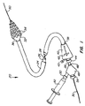
本発明によるステント展開システムの好ましい実施形態が図1に示されている。ステント展開システム20は、シース24と、シース24内にスライド自在に配置されたプッシャ・チューブ26と、プッシャ・チューブ26内にスライド自在に配置されたカテーテル・シャフト28とを備える。シース24、プッシャ・チューブ26、カテーテル・シャフト28は、血管内への配置や末梢血管から冠動脈への蛇行した経路に沿った位置決めに適したすべて可撓性の生体適合性材料で作製されている。ガイドワイヤ30が、導入と追跡を容易にするためにカテーテル・シャフト28内にスライド自在に配置可能である。好ましくはエラストマー製のバルーンである膨張可能な部材32が、カテーテル・シャフト28の遠端部に装着され、血管内への配置に適した非膨張形状と、血管内腔内へのステントの展開に適した膨張形状を有する。一連の管状のステント・セグメント34が、膨張可能な部材32の周縁部に配置され、膨張可能な部材によって膨張されて血管壁と接触するように構成されている。
A preferred embodiment of a stent deployment system according to the present invention is shown in FIG. The
膨張可能な部材32は、治療される血管領域のサイズと幾何形状に適した膨張形状を有する。好ましい実施形態では、膨張可能な部材32は、先細のまたは部分的に先細の形状を有し、膨張可能な部材32の近位の先端は、遠位の先端よりも大きい直径を有する。このことは、先細の血管内でのステント・セグメント34の最適な膨張を可能にする。治療された領域の近位の部分の1つまたは複数のステント・セグメント34が、より遠位に配置されたステント・セグメント34よりも大きく膨張されるべきである。もちろん、膨張可能な部材32は、以下で説明する、治療される領域に適した様々な形状を有してもよい。
The
ステント・セグメント34は、好ましくは互いに接続されておらず、膨張可能な部材32に対して独立に配置可能であり、様々な直径に独立に膨張可能であり、血管壁被覆を最適化し、可撓性を最大化する幾何形状を備える。このことは、選択された数のステント・セグメント34が、極めて長いまたは極めて短い病変を治療するために、かつ極めて曲がったまたは先細の血管領域内でも展開させることができる。本発明での使用に適したステントとステント・セグメントは、参照によって本明細書に組み込まれる、2002年11月27日に提出された同時係属出願第10/306,813号、および2003年1月17日に提出された仮出願第60/440839号で同一出願人によって開示されている。
The
シース24は、以下でより完全に説明するように膨張可能な部材32の近位の部分と係合し、その膨張を拘束する遠端部36を有する。好ましくは、シース24は、膨張可能な部材32が膨張されたとき膨張に抵抗するように補強され、壁の中に埋め込まれたまたは壁の周囲に配置された、金属製またはポリマー製の紐またはその他のタイプの補強材を有する。シース24の近端部38は、ハンドル40に取り付けられている。アクチュエータ42が、ハンドル40にスライド自在に装着され、プッシャ・チューブ26の近端部と結合されている。このようにして、ハンドル40に沿ってスライドするアクチュエータ42が、プッシャ・チューブ26をシース24に対して移動させる。密閉されたポート44が、ハンドル40の近端部に装着され、カテーテル・シャフト28を受けるように構成され、シャフトがハンドルに対してスライドできるようにしながら、その周りを流体密封とされている。密封されたポート44に装着されたフラッシュ・ポート45が、洗浄と潤滑のための流体の導入させるため、シース24の内部と連絡している。
The
カテーテル・シャフト28は、アダプタ48に装着された近端部46を有する。アダプタ48は、以下で説明するように、膨張流体を膨張可能な部材32に移送するために使用される注射器52などの膨張器機と結合するように構成されたポート50を有する。アダプタ48は、ガイドワイヤ30を受けるように構成され、ガイドワイヤをアダプタ48に対してスライドさせながら、その周囲を流体密封するように構成された止血弁54をさらに備える。
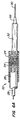
図2は、膨張可能な部材32が膨張されない状態にあるステント展開システム20の遠位の部分の断面を示している。カテーテル・シャフト28が、管状の外側シャフト56と管状の内側シャフト58を備え、それらの間に同軸の膨張内腔59を形成していることがわかるであろう。外側シャフト56と内側シャフト58は両方ともアダプタ48に固定され、したがって互いに対して固定されている。内側シャフト58は、ガイドワイヤ内腔61を区画している。外側シャフト56は、膨張可能な部材32の近端部62に装着された遠端部60を有する。内側シャフト58は、先細のノーズコーン66に装着された遠端部64を有する。膨張可能な部材32の遠端部68は、ノーズコーン66に接合されている。複数のステント・セグメント34が、膨張可能な部材32の周囲に配置され、好ましい実施形態では部材32に対してスライド自在である。プッシャ・チューブ26は、力を近位のステント・セグメント72に及ぼすために近位のステント・セグメント72と係合されるように構成された遠端部70を有する。シース24が、プッシャ・チューブ26、膨張可能な部材32の近位端、その上のステント・セグメント72の周囲に配置されている。膨張内腔59内へ導入される生理食塩水などの膨張流体が、膨張可能な部材32の内部を満たして、それを膨張させ、このようにしてステント・セグメント34を膨張させることを理解されよう。
FIG. 2 shows a cross-section of the distal portion of the
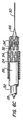
図3は、血管V内で使用中のステント展開システム20を示している。最初に、シース24が、膨張可能な部材32(およびその上のステント・セグメント34)を覆って位置決めされ、使用者が、ステント展開システム20を治療される血管領域内に位置決めする。その後、所望の長さの膨張される膨張可能な部材32と所望の数の展開されるステント・セグメント34’を露出させるために、膨張可能な部材32に対してシース24を近位方向に引き込む。その後、膨張流体を、膨張内腔59を通って膨張可能な部材32に導入し、膨張可能な部材32がステント・セグメント34’を膨張させて血管壁Wと係合状態にさせる。シース24が、膨張可能な部材32の近位の部分33の膨張を拘束し、シース24の遠位に露出された膨張可能な部材32の一部を、その上のステント・セグメント34’とともに膨張させる。
FIG. 3 shows the
その膨張状態では、膨張可能な部材は、逆のテーパを有する近位の端部部分71、上にステント・セグメント34が配置される作動部分73、作動部分73からノーズコーン66へテーパしている遠位の端部部分75を有する。好ましい実施形態では、作動部分73が、遠位の先端76での膨張された直径よりもよりも大きな膨張された直径を近位の先端74で有するように、膨張された状態の先細の外側形状を有する。膨張された直径は、展開されたステント・セグメント34’のすべてが血管壁Wとしっかりと係合するように、血管V内の先細の内腔L内の最適な膨張を提供するように選択される。冠動脈の用途に適した好ましい実施形態では、膨張可能な部材32が、近位の先端74の約3〜5mmの膨張された直径から遠位の先端76の約2〜4mmの膨張された直径へテーパしている。膨張可能な部材32は、好ましくは、近位の先端74と遠位の先端76のすべてを通して、約0.5〜5%の傾斜を有する一定の傾斜の連続的なテーパを有する。別法として、近位の先端74は、遠位の先端76と異なる傾斜でテーパとしてもよい、または以下で説明するように、近位の先端74と遠位の先端76のいずれかが、テーパを有さなくてもよい、またはその長さに沿って部分的にしかテーパ付けされていなくてもよい。
In its expanded state, the expandable member tapers from a proximal end portion 71 having an inverse taper, an actuating
ステント・セグメント34’の展開の後で、膨張可能な部材32がしぼんで、シース24内に近位に引き込まれる。膨張可能な部材32が引き込まれた後、膨張可能な部材32がステント・セグメント34を通って近位にスライドするとき、遠位の力がステント・セグメント34を定位置に保持するためにプッシャ・チューブ26上に維持される。膨張可能な部材32の外側面は、ステント・セグメント34を通って近位にスライドすることを可能にするように構成され、十分に滑らかであり、潤滑性であり、ステント・セグメント34を通る膨張可能な部材32の近位のスライド運動を阻止する切欠きまたはその他の表面形状がない。しかし、膨張可能な部材32は、その例を以下で説明する、このような運動を過度に阻止しないいくつかのタイプの表面形状や幾何形状を有してもよいことを理解されたい。膨張可能な部材32は、最も遠位のステント・セグメント34が、作動部分73の遠位の部分の周囲に配置されるように位置決めされている。次に、ステント展開システム20が、治療される別の血管領域に再配置され、そこでシース24が、所望の数のステント・セグメント34を露出させるために引き込まれ、プロセスが繰り返される。
Following deployment of
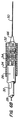
図4は、膨張可能な部材32が、遠位の方向に直径が減少する複数の円筒形の段差80を有するステント展開システム20のさらなる実施形態を示している。好ましい実施形態では、段差80は、作動部分73の全長に沿って設けられ、各段差80が、事前に選択された数のステント・セグメント34を収容するように構成されている。シース24を膨張可能な部材32に対してスライドさせることによって、所望の数の段差80がステント・セグメント34’の膨張のために露出されることがわかるであろう。一実施形態では、各段差80は、各段差80が1つのステント・セグメント34を保持するように、1つのステント・セグメント34の軸方向長さとほぼ等しい軸方向長さを有する。冠動脈の用途に対しては、1つのステント・セグメントの軸方向長さは、好ましくは2〜5mmの範囲である。各段差は、その近位側の隣接する段差の膨張された直径よりもわずかに小さい膨張された直径を有する。一実施形態では、近位の段差82は、3〜5mmの範囲の膨張された直径を有し、遠位の段差84は、2〜4mmの範囲の膨張された直径を有する。近位の段差82と遠位の段差84の間の各段差は、近位の段差82と遠位の段差84の直径の差をとり、2つの間の段差の数で割ることによって計算される、徐々に小さくなる直径を有する。各段差80が、その軸方向長さに沿って一定である膨張された直径であってもよいこと、または段差80いくつかまたはすべてが、段差80の近端部が段差80の遠端部よりも大きい膨張された直径を有するようにテーパされてもよいことを理解されたい。
FIG. 4 illustrates a further embodiment of the
図5に示す代替となる実施形態では、膨張可能な部材32が、2つのみの段差80A、80Bを有し、1つは近位の先端74よりも大きい膨張された直径であり、1つは遠位の先端76よりも大きい膨張された直径である。段差80A、80Bは、図4のように間に半径方向の壁を有して互いに隣接しているが、図5の実施形態では、段差80A、80Bはテーパ部分86によって分離される。段差80A、80Bのそれぞれが一定の膨張された直径を有してテーパされていなくてもよい、またはいずれかの段差が遠位方向にテーパされてもよい。一実施形態では、近位の段差80Aが、約3〜5mmの膨張された直径と約5〜15mmの軸方向長さを有し、遠位の段差80Aが、約2〜4mmの膨張された直径と約5〜15mmの軸方向長さを有する。シース32は、所望の数のステント・セグメント34’を露出させるように膨張可能な部材32を覆ってスライド自在に位置決めされる。それによって近位の段差80Aと潜在的に遠位の段差80Bの露出された長さを調節する。
In the alternative embodiment shown in FIG. 5, the
例示的な方法では、図5のステント展開システム20が、遠位の段差80Bが血管V内の狭窄性病変S内にあり、近位の段差80Aが病変Sの近端部と隣接するように、位置決めされる。このようにして、膨張可能な部材32が、血管Vがより大きな直径を有する病変Sの近くで大きな直径に膨張し、それによってステント・セグメント34’が完全に膨張されて血管壁Wと係合されることを確実にする。
In the exemplary method, the
図6A〜6Dは、ステント展開システム20の使用を示している。図6Aは、1つまたは複数のステント・セグメント34を展開した後の血管内のステント展開システム20を示している。膨張可能な部材32が、シース24の遠位側に配置され、膨張可能な部材32の露出された部分にステント・セグメント34を有していない。血管の別の領域を治療するために、膨張可能な部材32がステント・セグメントを通って近位側へ移動するときステント・セグメント34を定位置に保持するために遠位の力をプッシャ・チューブ26で維持させながら、膨張可能な部材32をシース24内に引き込む。もちろん、膨張可能な部材32が、ステント・セグメント34を膨張可能な部材32上で遠位側へスライドさせるためにプッシャ・チューブ26とシース24をスライドさせながら、別法として定位置に保持させてもよいことを理解されたい。ステント・セグメント34は、図6Bに示すように、最も遠位のステント・セグメントを、膨張可能な部材32の遠端部の近くにあるように配置させる。この位置合わせを容易にするために、ノーズコーン66が、ステント・セグメント34と係合し、さらなる運動を停止させるように構成された大きい近端部分(図示せず)を有してもよい。
6A-6D illustrate the use of the
ステント展開システム20が次に、治療される血管内の異なる領域へ再配置される。いったん再配置された後、展開される所望の数のステント・セグメント34’を露出させるためにプッシャ・チューブ26の圧力を維持しながら、シース24を膨張可能な部材32に対して近位方向に引き込む。好ましくは、次に、図6Cに示すように、シース24内のステント・セグメント34が、これらの展開されるステント・セグメント34’からスライド自在に分離されるように、プッシャ・チューブ26に力を加えずに、シース24を追加の小さな距離だけ引き込む。このことは、シース24内のステント・セグメント34が、膨張可能な部材32が膨張されるとき、確実に膨張しないように、すなわち外れないようにする。このことを容易にするために、参照によって本明細書に組み込まれる2003年4月10日に提出された同一出願人による同時係属出願第 号、代理人整理番号第21629−000330号に記載のように、ステント弁(図示せず)が、ステント・セグメント34と選択的に係合し、それらをシース内に保持させるためにシース24の遠端部に設けられてもよい。
シース24の遠位方向に露出された所望の数のステント・セグメント34’とともに、膨張可能な部材32が、膨張内腔59を通って膨張流体を導入することによって膨張させられる。これによって、図6Dに示すように、ステント・セグメント34’に半径方向の力を及ぼし、それらを膨張させ、塑性変形させて血管壁と係合する膨張された形状にする。膨張可能な部材32が次に、収縮させられ、シース24内に引き込まれる。患者の体からステント展開システムを取り外すことなく、血管内または一連の血管内の様々な長さの複数の病変を治療するために、このプロセスを繰り返えすことができる。
With the desired number of
上記で示したように、好ましい実施形態では、ステント展開システム20の膨張可能な部材32は、膨張可能な部材に対してステント・セグメント34を遠位方向へスライドさせることができるように構成されている。しかし、膨張可能な部材32は、いったん膨張可能な部材32上に配置された後、ステント・セグメント34が近位側にスライドするのを防止すべきである。このことは、シース24が膨張可能な部材32とステント・セグメント34に対して近位方向に引き込まれるとき、特に困難になる。シース24は、ステント・セグメント34と係合して、それらを膨張可能な部材32に対して近位の方向に押しもどす。膨張可能な部材32上でのステント・セグメント34の位置を維持するのを助けるために、膨張可能な部材32は、ステント・セグメント34と係合し、ステント・セグメントが膨張可能な部上を遠位方向にはスライドすることを許す一方、膨張可能な部材上を近位方向にスライドすることを阻止する表面形状を有してもよい。図7A〜7Cに示した一実施形態では、膨張可能な部材32が、外向きにかつ膨張可能な部材32の表面から遠位方向に突き出でている複数の弾力性かつ可撓性の突起88を有する。突起88は、それによってステント・セグメント34が遠位方向に容易にスライドするが、突起88の遠位の先端90との係合のため近位方向のスライドを阻止される、膨張可能な部材32の表面上の「木目」を作成するように、膨張可能な部材32の遠端部に向かって傾斜されている。突起88は、好ましくはエラストマー製材料であり、成型または浸漬によって膨張可能な部材32と一体に形成されるが、別法として、接着、熱溶接またはその他の手段によって膨張可能な部材32の表面に取り付けられてもよい。さらなる代替形態として、適切な「木目をつけた」特徴を有する織物またはシートを、膨張可能な部材32の表面に固定してもよい。
As indicated above, in a preferred embodiment, the
好ましくは、突起88が、ステント・セグメント34の間またはその中の空間内に突き出すように膨張可能な部材32上に配置されている。図7Bに概略的に示す一実施形態では、突起88は膨張可能な部材32上に環状の列と並列して配置される。その列は、各ステント・セグメント34の間の空間内に入るように選択された距離だけ離隔されている。
Preferably, the
ある状況では、ステント・セグメント34を膨張可能な部材32に対して近位に移動させることが望ましい。例えば、上記で説明したように、所望の数のステント・セグメント34が、展開のためにシース24の遠位方向に露出されたとき、ステント・セグメント34’を膨張可能な部材32に対して近位方向に短い距離だけシース24内で移動させることが望ましいことがある。図7Cに示すように、近位の方向の十分な力に応答して、突起88は、近位の方向に曲がるように構成され、ステント・セグメントが膨張可能な部材32に対して近位方向に移動できる。図示した実施形態では、ステント弁92が、参照によって本明細書に組み込まれる2003年4月10提出された同一出願人による同時係属出願第 号、代理人整理番号第21629−000330号に記載のように、シース24の遠端部に配置されている。ステント弁92は、ステント・セグメント34と係合するように構成され、遠位の先端90が近位方向を指して突起88を曲げるのに十分な近位の力をそれに対して及ぼし、ステント・セグメント34を膨張可能な部材32に対して近位方向に移動させる。ステント・セグメント34をシース24の遠位方向に展開させることが望ましいとき、ステント弁92を過ぎてステント・セグメント34を押しやるようにプッシャ・チューブ26に力を及ぼす。
In certain situations, it may be desirable to move the
突起88が、膨張可能な部材32の壁内での引張力また応力緩和に応答して、多かれ少なかれ外向きに突き出すように形成されてもよい。例えば、膨張可能な部材32が収縮され、引張力下にないとき、突起88は、膨張可能な部材32の外側面に対して平坦に法線方向にあるように構成されることができる。膨張可能な部材32の壁が、外側シャフト56(図2)に対して内側シャフト58に遠位の力を及ぼすことによって、膨張可能な部材32を部分的に膨張させることによって引張力を加えられるまたはわずかに伸長されるとき、ステント・セグメント34との係合を増加させるために突起88がさらに外向きに突き出ることになる。別法として、突起88は、膨張可能な部材32が収縮され、引張力の下にないとき、さらに外向きに法線方向に延びるように構成させられ、膨張可能な部材32上でのステント・セグメント34の近位の運動を阻止してもよい。膨張可能な部材32が膨張される、または引張られるとき、突起88は、ステント・セグメント34との干渉を減少させるために膨張可能な部材32の外側面に対して平面状であるように構成されてもよい。このようにして、使用者は、突起88とステント・セグメント34の間の係合の程度を制御してもよい。例えば、膨張可能な部材32をステント・セグメント34に対して近位方向に引き込むとき、膨張可能な部材上でのスライド運動に対する抵抗がほとんどないことが望ましい。しかし、シース24が所望の数のステント・セグメントを露出させるために引き込まれるとき、ステント・セグメント34の近位の運動に対する高い程度の抵抗が必要とされる。次に、所望の数のステント・セグメント34がシース24の遠位方向に露出されたとき、シース24内の残りのステント・セグメントを膨張可能な部材32に対してさらに近位の方向に引くことが望ましい。この点で、シース24内でのステント・セグメント34の運動との干渉を最小化することが望ましい。引張力を付加および解放することによって、または膨張可能な部材32を部分的に膨張させ収縮させることによって、使用者は、これらの状況のそれぞれで膨張可能な部材32に対するステント・セグメント34の運動を選択的に阻止または可能にすることができる。
The
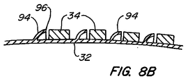
ステント展開システム20での膨張可能な部材32のさらなる実施形態が、図8A〜8Cに示されている。この実施形態では、膨張可能な部材32は、ステント・セグメント34(明確には図示せず)と係合するように構成された複数の可撓性、弾力性の環状リブ94を有する。図8Bに示すような断面図では、各リブ94は、外縁部96が遠位の方向に向けられ、近位側で凸状であり、遠位側で凹状である遠位方向に曲がった壁を有する。これは、ステント・セグメント34が、リブ94上で遠位方向に比較的容易にスライドすることができるが、リブ94上でのステント・セグメント34の近位の運動を阻止する。リブ94は、膨張可能な部材32と一体に形成されてもよい、または別個に形成されて、接着、熱溶接またはその他の手段によってそれに固定されてもよい。好ましくは、リブ94は、ステント・セグメント34がリブ94の間に配置されるように、ステント・セグメント34の軸方向長さに対応するある距離だけ離隔されている。
A further embodiment of the
リブ94が好ましくは、ステント・セグメント34に対する十分な力に応答して近位の方向に偏向可能または外転可能であることが図8Cでわかる。図示した実施形態では、シース24が膨張可能な部材32に対して引き込まれるとき、ステント弁92がステント・セグメント34と係合し、それに近位の力を及ぼす。リブ94の外縁部96が、近位の方向に偏向され、リブ94を外転させ、ステント・セグメント34をその上で近位の方向に移動させる。リブ94が、図7A〜7Cに関連して上記で説明したものと同様な方式で膨張可能な部材32に引張力を加えることまたはそれを膨張させることに応答して、外向きにさらに延びるように、または膨張可能な部材32の表面に対してより平面状であるように構成されてもよいことをさらに理解されたい。このことは、使用者が、ステント・セグメント34との係合の程度を選択的に制御することを可能にする。
It can be seen in FIG. 8C that the
本発明によるステント展開システムのさらなる実施形態が図9に示されている。ここでは、シース24とプッシャ・チューブ26が明確化の目的で取り外されている。この実施形態では、コア部材100が、膨張可能な部材32の内部空間内の内側シャフト58の遠位の部分に装着されている。膨張可能な部材32がコア部材100の周囲に延びており、膨張流体が膨張内腔59を介して導入されるとき、コア部材100から外向きに膨張するように、それに取り付けられてはいない。ステント・セグメント34が、膨張可能な部材32上に配置され、膨張可能な部材32上で軸方向にスライド自在であるように維持しながら、コア部材100を内向きに押す。コア部材100が、ステント・セグメント34に押されてそれと係合するが、ステント・セグメント34が膨張可能な部材32上でスライドすることを防止するほどは押しつけられないように、膨張可能な部材32の収縮された直径と通常ほとんど同じ、またはわずかに小さい横方向寸法(外側面)を有する。コア材料100は、膨張可能な部材32とステント・セグメント34の間で摩擦を生じさせ、ステント・セグメントのスライド自在な運動に対する抵抗を生じさせるためにステント・セグメント34を外向きに押圧する、圧縮可能な、弾力性のエラストマーから成る。このようにして、ステント・セグメント34は、十分な力が、プッシャ・チューブ26またはシース24によってステント・セグメントに及ぼされない場合、膨張可能な部材32上で静止しつづける傾向がある。このことは、選択された数のステント・セグメント34を膨張可能な部材32上に配置すること、および所望の数のステント・セグメントを展開させるように他のステント・セグメント34を膨張可能な部材32に対して引き込むことで、より大きな制御を使用者に与える。
A further embodiment of a stent deployment system according to the present invention is shown in FIG. Here, the
上記のことは、本発明の好ましい実施形態の完全な説明であるが、様々な追加、代替、修正、等価および代用が、本発明の範囲から逸脱することなく可能である。したがって、上記のことは、添付の特許請求の範囲によって定義される本発明の範囲を限定するものであると考えるべきではない。 While the above is a complete description of the preferred embodiments of the invention, various additions, substitutions, modifications, equivalents and substitutions are possible without departing from the scope of the invention. Therefore, the above should not be taken as limiting the scope of the invention which is defined by the appended claims.
Claims (68)
近端部と遠端部を有する細長いカテーテル・シャフトと、
近位端と遠位端を有し、近位端が第1の膨張された直径を有し、遠位端が第2の膨張された直径を有し、第1の膨張された直径が、内腔テーパにほぼ対応する第2の膨張された直径よりも大きい、カテーテル・シャフトにその遠端部の近くで装着された膨張可能な部材と、
膨張可能な部材の近位端と遠位端にそれとともに膨張するようにスライド自在に配置可能な複数の独立したステント・セグメントであって、各ステント・セグメントが、少なくとも1つの他のステント・セグメントとは潜在的に異なる膨張された直径に膨張可能であるステント・セグメントとを備え、
膨張可能な部材が、近位端から遠位端へのステント・セグメントのスライド自在な進行に適した外側面を有する、ステント展開システム。 A stent deployment system for deploying one or more stents in a blood vessel having a lumen taper comprising:
An elongated catheter shaft having a proximal end and a distal end;
Having a proximal end and a distal end, the proximal end having a first expanded diameter, the distal end having a second expanded diameter, and the first expanded diameter being An inflatable member attached to the catheter shaft near its distal end that is larger than a second inflated diameter substantially corresponding to the lumen taper;
A plurality of independent stent segments slidably disposed to expand therewith at a proximal end and a distal end of an expandable member, each stent segment being at least one other stent segment A stent segment that is expandable to a potentially different expanded diameter,
A stent deployment system, wherein the expandable member has an outer surface suitable for slidable progression of the stent segment from the proximal end to the distal end.
近端部と遠端部を有する細長いカテーテル・シャフトと、
近位端の第1の膨張された直径から、内腔テーパに一般に対応する遠位の端部の第2の膨張された直径へ膨張されたときテーパされる、カテーテル・シャフトに遠端部の近くで装着された膨張可能な部材と、
近位端と遠位端の位置で膨張可能な部材の上にそれとともに膨張するようにスライド自在に配置可能な複数の独立したステント・セグメントであって、各ステント・セグメントが、少なくとも1つの他のステント・セグメントとは潜在的に異なる膨張された直径に独立して膨張可能であるステント・セグメントとを備え、
膨張可能な部材が、近位端から遠位端へのステント・セグメントのスライド自在な進行に適した外側面を有する、ステント展開システム。 A stent deployment system for deploying one or more stents in a blood vessel having a lumen taper comprising:
An elongated catheter shaft having a proximal end and a distal end;
The distal end of the catheter shaft is tapered when expanded from a first expanded diameter at the proximal end to a second expanded diameter at a distal end generally corresponding to a lumen taper. An inflatable member mounted nearby;
A plurality of independent stent segments slidably disposed on and expandable therewith at proximal and distal positions, each stent segment having at least one other A stent segment that is independently expandable to an expanded diameter that is potentially different from the stent segment of
A stent deployment system, wherein the expandable member has an outer surface suitable for slidable progression of the stent segment from the proximal end to the distal end.
遠端部の近くに膨張可能な部材を有するカテーテルを血管内に経皮的に導入するステップと、
第1と第2のステント・セグメントが膨張可能な部材に対して独立に運動可能であり、第1のステント・セグメントが膨張可能な部材の近位端上にあり、第2のステント・セグメントが膨張可能な部材の遠位端上にあるように、第1の複数の独立したステント・セグメントを膨張可能な部材上に配置するステップと、
近位端が第1の膨張された直径を有し、遠位端が第1の膨張された直径よりも小さい第2の膨張された直径を有するように膨張可能な部材を膨張させ、第1のステント・セグメントが第2のステント・セグメントよりも大きい直径に膨張させるステップと
を含む方法。 In a method of deploying a stent segment within a blood vessel having a lumen taper,
Introducing a catheter having an expandable member near the distal end percutaneously into the blood vessel;
The first and second stent segments are independently movable with respect to the expandable member, the first stent segment is on the proximal end of the expandable member, and the second stent segment is Placing a first plurality of independent stent segments on the expandable member such that the first plurality of independent stent segments are on the distal end of the expandable member;
Inflating the inflatable member such that the proximal end has a first expanded diameter and the distal end has a second expanded diameter less than the first expanded diameter; Expanding the stent segment to a larger diameter than the second stent segment.
遠端部の近くでカテーテル・シャフトに装着され、外向きに突き出した複数の表面形状を有する膨張可能な部材と、
膨張可能な部材上にスライド自在に配置可能なステントとを備え、
表面形状が、膨張可能な部材に対する遠位方向へのステントのスライド運動を可能にし、膨張可能な部材に対する近位方向へのステントのスライド運動を阻止する、ステント展開システム。 An elongated catheter shaft having a proximal end and a distal end;
An inflatable member attached to the catheter shaft near the distal end and having a plurality of outwardly protruding surface shapes;
A stent slidably disposed on the expandable member;
A stent deployment system, wherein the surface shape allows sliding movement of the stent in a distal direction relative to the expandable member and prevents proximal sliding movement of the stent relative to the expandable member.
外側面を有し、遠端部の近くでカテーテル・シャフトに装着される膨張可能な部材と、
膨張可能な部材の外側面上でスライド自在に配置可能なステントとを備え、
膨張可能な部材の外側面が、膨張可能な部材に対する遠位方向のステントのスライド運動を許し、膨張可能な部材に対する近位方向のステントのスライド運動を阻止するように構成されている、ステント展開システム。 An elongated catheter shaft having a proximal end and a distal end;
An inflatable member having an outer surface and attached to the catheter shaft near the distal end;
A stent slidably disposed on the outer surface of the inflatable member;
Stent deployment wherein the outer surface of the expandable member is configured to allow distal movement of the stent relative to the expandable member and to prevent proximal movement of the stent relative to the expandable member. system.
Applications Claiming Priority (2)
| Application Number | Priority Date | Filing Date | Title |
|---|---|---|---|
| US10/458,062 US7241308B2 (en) | 2003-06-09 | 2003-06-09 | Stent deployment systems and methods |
| PCT/US2004/016834 WO2004110303A2 (en) | 2003-06-09 | 2004-05-28 | Stent deployment systems and methods |
Publications (2)
| Publication Number | Publication Date |
|---|---|
| JP2007500577A true JP2007500577A (en) | 2007-01-18 |
| JP2007500577A5 JP2007500577A5 (en) | 2007-07-05 |
Family
ID=33490420
Family Applications (1)
| Application Number | Title | Priority Date | Filing Date |
|---|---|---|---|
| JP2006533474A Pending JP2007500577A (en) | 2003-06-09 | 2004-05-28 | Stent deployment system and method |
Country Status (6)
| Country | Link |
|---|---|
| US (4) | US7241308B2 (en) |
| EP (1) | EP1635902A4 (en) |
| JP (1) | JP2007500577A (en) |
| AU (1) | AU2004247052B2 (en) |
| CA (1) | CA2528243A1 (en) |
| WO (1) | WO2004110303A2 (en) |
Cited By (6)
| Publication number | Priority date | Publication date | Assignee | Title |
|---|---|---|---|---|
| CN101926700A (en) * | 2010-07-13 | 2010-12-29 | 北京迈迪顶峰医疗科技有限公司 | Periodically replaceable valve scaffold group and conveyor thereof |
| JP2011510796A (en) * | 2008-02-05 | 2011-04-07 | シルク・ロード・メディカル・インコーポレイテッド | Intervention catheter system and method |
| US8343089B2 (en) | 2003-11-21 | 2013-01-01 | Silk Road Medical, Inc. | Method and apparatus for treating a carotid artery |
| US8574245B2 (en) | 2008-08-13 | 2013-11-05 | Silk Road Medical, Inc. | Suture delivery device |
| US8740834B2 (en) | 2007-07-18 | 2014-06-03 | Silk Road Medical, Inc. | Methods and systems for establishing retrograde carotid arterial blood flow |
| US8858490B2 (en) | 2007-07-18 | 2014-10-14 | Silk Road Medical, Inc. | Systems and methods for treating a carotid artery |
Families Citing this family (119)
| Publication number | Priority date | Publication date | Assignee | Title |
|---|---|---|---|---|
| US7018401B1 (en) | 1999-02-01 | 2006-03-28 | Board Of Regents, The University Of Texas System | Woven intravascular devices and methods for making the same and apparatus for delivery of the same |
| EP1258230A3 (en) | 2001-03-29 | 2003-12-10 | CardioSafe Ltd | Balloon catheter device |
| GB0121980D0 (en) | 2001-09-11 | 2001-10-31 | Cathnet Science Holding As | Expandable stent |
| US7309350B2 (en) | 2001-12-03 | 2007-12-18 | Xtent, Inc. | Apparatus and methods for deployment of vascular prostheses |
| US20040186551A1 (en) | 2003-01-17 | 2004-09-23 | Xtent, Inc. | Multiple independent nested stent structures and methods for their preparation and deployment |
| US7137993B2 (en) | 2001-12-03 | 2006-11-21 | Xtent, Inc. | Apparatus and methods for delivery of multiple distributed stents |
| US7351255B2 (en) | 2001-12-03 | 2008-04-01 | Xtent, Inc. | Stent delivery apparatus and method |
| US7892273B2 (en) | 2001-12-03 | 2011-02-22 | Xtent, Inc. | Custom length stent apparatus |
| US7182779B2 (en) | 2001-12-03 | 2007-02-27 | Xtent, Inc. | Apparatus and methods for positioning prostheses for deployment from a catheter |
| US8080048B2 (en) | 2001-12-03 | 2011-12-20 | Xtent, Inc. | Stent delivery for bifurcated vessels |
| US7270668B2 (en) * | 2001-12-03 | 2007-09-18 | Xtent, Inc. | Apparatus and methods for delivering coiled prostheses |
| US20030135266A1 (en) * | 2001-12-03 | 2003-07-17 | Xtent, Inc. | Apparatus and methods for delivery of multiple distributed stents |
| US7294146B2 (en) | 2001-12-03 | 2007-11-13 | Xtent, Inc. | Apparatus and methods for delivery of variable length stents |
| US7147656B2 (en) | 2001-12-03 | 2006-12-12 | Xtent, Inc. | Apparatus and methods for delivery of braided prostheses |
| GB0309616D0 (en) | 2003-04-28 | 2003-06-04 | Angiomed Gmbh & Co | Loading and delivery of self-expanding stents |
| US7241308B2 (en) | 2003-06-09 | 2007-07-10 | Xtent, Inc. | Stent deployment systems and methods |
| US7553324B2 (en) * | 2003-10-14 | 2009-06-30 | Xtent, Inc. | Fixed stent delivery devices and methods |
| US20050080475A1 (en) * | 2003-10-14 | 2005-04-14 | Xtent, Inc. A Delaware Corporation | Stent delivery devices and methods |
| US7713296B2 (en) * | 2003-10-16 | 2010-05-11 | Minavasys, Sa | Catheter system for stenting bifurcated vessels |
| US7403966B2 (en) * | 2003-12-08 | 2008-07-22 | Freescale Semiconductor, Inc. | Hardware for performing an arithmetic function |
| US7326236B2 (en) | 2003-12-23 | 2008-02-05 | Xtent, Inc. | Devices and methods for controlling and indicating the length of an interventional element |
| US7323006B2 (en) | 2004-03-30 | 2008-01-29 | Xtent, Inc. | Rapid exchange interventional devices and methods |
| US20050228477A1 (en) * | 2004-04-09 | 2005-10-13 | Xtent, Inc. | Topographic coatings and coating methods for medical devices |
| US8317859B2 (en) | 2004-06-28 | 2012-11-27 | J.W. Medical Systems Ltd. | Devices and methods for controlling expandable prostheses during deployment |
| US20050288766A1 (en) * | 2004-06-28 | 2005-12-29 | Xtent, Inc. | Devices and methods for controlling expandable prostheses during deployment |
| US20060069424A1 (en) * | 2004-09-27 | 2006-03-30 | Xtent, Inc. | Self-constrained segmented stents and methods for their deployment |
| EP1793765B1 (en) * | 2004-09-28 | 2011-03-16 | Cordis Corporation | Thin film medical device and delivery system |
| US7306623B2 (en) * | 2005-01-13 | 2007-12-11 | Medtronic Vascular, Inc. | Branch vessel graft design and deployment method |
| US20080188803A1 (en) * | 2005-02-03 | 2008-08-07 | Jang G David | Triple-profile balloon catheter |
| US20060184227A1 (en) * | 2005-02-11 | 2006-08-17 | Medtronic Vascular, Inc. | Increased friction inner member for stent-graft deployment |
| US20060206187A1 (en) * | 2005-03-09 | 2006-09-14 | Cook Incorporated | Stent delivery system |
| US7402168B2 (en) * | 2005-04-11 | 2008-07-22 | Xtent, Inc. | Custom-length stent delivery system with independently operable expansion elements |
| US7381048B2 (en) * | 2005-04-12 | 2008-06-03 | Advanced Cardiovascular Systems, Inc. | Stents with profiles for gripping a balloon catheter and molds for fabricating stents |
| US8641746B2 (en) * | 2005-05-31 | 2014-02-04 | J.W. Medical Systems Ltd. | In situ stent formation |
| US7320702B2 (en) | 2005-06-08 | 2008-01-22 | Xtent, Inc. | Apparatus and methods for deployment of multiple custom-length prostheses (III) |
| US7927362B2 (en) * | 2005-07-21 | 2011-04-19 | Boston Scientific Scimed, Inc. | Laser ablated elastomer sheath profiles to enables stent securement |
| US8790396B2 (en) * | 2005-07-27 | 2014-07-29 | Medtronic 3F Therapeutics, Inc. | Methods and systems for cardiac valve delivery |
| US20070156223A1 (en) * | 2005-12-30 | 2007-07-05 | Dennis Vaughan | Stent delivery system with improved delivery force distribution |
| US20070179587A1 (en) * | 2006-01-30 | 2007-08-02 | Xtent, Inc. | Apparatus and methods for deployment of custom-length prostheses |
| WO2007109621A2 (en) | 2006-03-20 | 2007-09-27 | Xtent, Inc. | Apparatus and methods for deployment of linked prosthetic segments |
| US8535368B2 (en) | 2006-05-19 | 2013-09-17 | Boston Scientific Scimed, Inc. | Apparatus for loading and delivering a stent |
| US20070281117A1 (en) * | 2006-06-02 | 2007-12-06 | Xtent, Inc. | Use of plasma in formation of biodegradable stent coating |
| US20070288077A1 (en) * | 2006-06-07 | 2007-12-13 | Cherik Bulkes | Self-anchoring electrical lead with multiple electrodes |
| WO2007146076A2 (en) * | 2006-06-07 | 2007-12-21 | Cherik Bulkes | Biological tissue stimulator with flexible electrode carrier |
| WO2007146075A2 (en) * | 2006-06-07 | 2007-12-21 | Cherik Bulkes | Analog signal transition detector |
| US8240020B2 (en) * | 2006-06-30 | 2012-08-14 | Advanced Cardiovascular Systems, Inc. | Stent retention mold and method |
| US20080269865A1 (en) * | 2006-08-07 | 2008-10-30 | Xtent, Inc. | Custom Length Stent Apparatus |
| US20080051867A1 (en) * | 2006-08-28 | 2008-02-28 | Davila Luis A | Multiple in vivo implant delivery device |
| US8323325B2 (en) * | 2006-09-25 | 2012-12-04 | Boston Scientific Scimed, Inc. | Balloon with wings for rotational stent |
| KR101297043B1 (en) | 2006-10-22 | 2013-08-14 | 이데브 테크놀로지스, 아이엔씨. | Methods for securing strand ends and the resulting devices |
| EP2083767B1 (en) | 2006-10-22 | 2019-04-03 | IDEV Technologies, INC. | Devices for stent advancement |
| US20080105436A1 (en) * | 2006-11-02 | 2008-05-08 | Schlumberger Technology Corporation | Cutter Assembly |
| US20080132988A1 (en) * | 2006-12-01 | 2008-06-05 | Scimed Life Systems, Inc. | Balloon geometry for delivery and deployment of shape memory polymer stent with flares |
| US20080146489A1 (en) * | 2006-12-15 | 2008-06-19 | Pacetti Stephen D | Regional delivery of therapeutic agents for the treatment of vascular diseases |
| US20080199510A1 (en) * | 2007-02-20 | 2008-08-21 | Xtent, Inc. | Thermo-mechanically controlled implants and methods of use |
| US8486132B2 (en) | 2007-03-22 | 2013-07-16 | J.W. Medical Systems Ltd. | Devices and methods for controlling expandable prostheses during deployment |
| US8366628B2 (en) * | 2007-06-07 | 2013-02-05 | Kenergy, Inc. | Signal sensing in an implanted apparatus with an internal reference |
| US8545432B2 (en) | 2009-06-03 | 2013-10-01 | Silk Road Medical, Inc. | System and methods for controlling retrograde carotid arterial blood flow |
| WO2009018248A1 (en) | 2007-07-30 | 2009-02-05 | Audubon Technologies, Llc | Device for maintaining patent paranasal sinus ostia |
| US20100274226A1 (en) * | 2007-09-06 | 2010-10-28 | Cook Incorporated | Deployment Catheter |
| US8858608B2 (en) * | 2007-12-10 | 2014-10-14 | Cook Medical Technologies Llc | Lubrication apparatus for a delivery and deployment device |
| US10022250B2 (en) | 2007-12-12 | 2018-07-17 | Intact Vascular, Inc. | Deployment device for placement of multiple intraluminal surgical staples |
| US8128677B2 (en) | 2007-12-12 | 2012-03-06 | Intact Vascular LLC | Device and method for tacking plaque to a blood vessel wall |
| US7896911B2 (en) | 2007-12-12 | 2011-03-01 | Innovasc Llc | Device and method for tacking plaque to blood vessel wall |
| US10166127B2 (en) | 2007-12-12 | 2019-01-01 | Intact Vascular, Inc. | Endoluminal device and method |
| US9375327B2 (en) | 2007-12-12 | 2016-06-28 | Intact Vascular, Inc. | Endovascular implant |
| US9603730B2 (en) | 2007-12-12 | 2017-03-28 | Intact Vascular, Inc. | Endoluminal device and method |
| US7963987B2 (en) * | 2007-12-28 | 2011-06-21 | Cook Medical Technologies Llc | Sequential implant delivery system |
| US8715332B2 (en) * | 2008-01-15 | 2014-05-06 | Boston Scientific Scimed, Inc. | Expandable stent delivery system with outer sheath |
| CN101519952A (en) * | 2008-02-25 | 2009-09-02 | 普拉德研究及开发股份有限公司 | Knife tool component |
| US9101503B2 (en) | 2008-03-06 | 2015-08-11 | J.W. Medical Systems Ltd. | Apparatus having variable strut length and methods of use |
| US10716573B2 (en) | 2008-05-01 | 2020-07-21 | Aneuclose | Janjua aneurysm net with a resilient neck-bridging portion for occluding a cerebral aneurysm |
| US10028747B2 (en) | 2008-05-01 | 2018-07-24 | Aneuclose Llc | Coils with a series of proximally-and-distally-connected loops for occluding a cerebral aneurysm |
| US20110152997A1 (en) * | 2008-06-05 | 2011-06-23 | Daniel John Kelly | Delivery system for multiple stents |
| EP2293838B1 (en) | 2008-07-01 | 2012-08-08 | Endologix, Inc. | Catheter system |
| CN102149421B (en) * | 2008-09-09 | 2014-12-10 | 普尔蒙克斯股份有限公司 | Systems and methods for inhibiting secretion flow into a functional assessment catheter |
| GB0816965D0 (en) * | 2008-09-16 | 2008-10-22 | Angiomed Ag | Stent device adhesively bonded to a stent device pusher |
| US8821562B2 (en) | 2008-09-25 | 2014-09-02 | Advanced Bifurcation Systems, Inc. | Partially crimped stent |
| US8769796B2 (en) | 2008-09-25 | 2014-07-08 | Advanced Bifurcation Systems, Inc. | Selective stent crimping |
| CN102215780B (en) | 2008-09-25 | 2015-10-14 | 高级分支系统股份有限公司 | Part crimped stent |
| US11298252B2 (en) | 2008-09-25 | 2022-04-12 | Advanced Bifurcation Systems Inc. | Stent alignment during treatment of a bifurcation |
| GB0901496D0 (en) | 2009-01-29 | 2009-03-11 | Angiomed Ag | Delivery device for delivering a stent device |
| US10772717B2 (en) | 2009-05-01 | 2020-09-15 | Endologix, Inc. | Percutaneous method and device to treat dissections |
| EP2424447A2 (en) | 2009-05-01 | 2012-03-07 | Endologix, Inc. | Percutaneous method and device to treat dissections |
| GB0909319D0 (en) | 2009-05-29 | 2009-07-15 | Angiomed Ag | Transluminal delivery system |
| JP5588511B2 (en) | 2009-07-27 | 2014-09-10 | エンドロジックス、インク | Stent graft |
| JP5455492B2 (en) * | 2009-07-30 | 2014-03-26 | 日本コヴィディエン株式会社 | Stylet and catheter set |
| US9358140B1 (en) | 2009-11-18 | 2016-06-07 | Aneuclose Llc | Stent with outer member to embolize an aneurysm |
| WO2011119883A1 (en) | 2010-03-24 | 2011-09-29 | Advanced Bifurcation Systems, Inc. | Stent alignment during treatment of a bifurcation |
| CN103037816B (en) | 2010-03-24 | 2018-12-28 | 高级分支系统股份有限公司 | System and method for handling furcation |
| AU2011232360B2 (en) | 2010-03-24 | 2015-10-08 | Advanced Bifurcation Systems Inc. | Methods and systems for treating a bifurcation with provisional side branch stenting |
| JP2013523263A (en) * | 2010-04-01 | 2013-06-17 | ゼノリス・メディカル・リミテッド | Scalable devices and usage |
| US9023095B2 (en) | 2010-05-27 | 2015-05-05 | Idev Technologies, Inc. | Stent delivery system with pusher assembly |
| US9393100B2 (en) | 2010-11-17 | 2016-07-19 | Endologix, Inc. | Devices and methods to treat vascular dissections |
| EP2672932B1 (en) | 2011-02-08 | 2018-09-19 | Advanced Bifurcation Systems, Inc. | System for treating a bifurcation with a fully crimped stent |
| WO2012109382A2 (en) | 2011-02-08 | 2012-08-16 | Advanced Bifurcation Systems, Inc. | Multi-stent and multi-balloon apparatus for treating bifurcations and methods of use |
| WO2012118901A1 (en) | 2011-03-01 | 2012-09-07 | Endologix, Inc. | Catheter system and methods of using same |
| US10285831B2 (en) | 2011-06-03 | 2019-05-14 | Intact Vascular, Inc. | Endovascular implant |
| CA2986656A1 (en) | 2012-01-25 | 2013-08-01 | Intact Vascular, Inc. | Endoluminal device and method |
| US9254212B2 (en) * | 2012-04-06 | 2016-02-09 | Abbott Cardiovascular Systems Inc. | Segmented scaffolds and delivery thereof for peripheral applications |
| US20140135907A1 (en) | 2012-11-09 | 2014-05-15 | Medtronic CV Luxembourg S.a.r.l. | Medical Device Delivery System and Methods of Delivering Medical Devices |
| ES2960917T3 (en) | 2013-03-14 | 2024-03-07 | Neuravi Ltd | Clot retrieval device to remove occlusive clots from a blood vessel |
| US9907684B2 (en) | 2013-05-08 | 2018-03-06 | Aneuclose Llc | Method of radially-asymmetric stent expansion |
| US10004834B2 (en) | 2013-09-13 | 2018-06-26 | Abbott Cardiovascular Systems Inc. | Braided scaffolds |
| US9375336B1 (en) | 2015-01-29 | 2016-06-28 | Intact Vascular, Inc. | Delivery device and method of delivery |
| US9456914B2 (en) | 2015-01-29 | 2016-10-04 | Intact Vascular, Inc. | Delivery device and method of delivery |
| US9192500B1 (en) | 2015-01-29 | 2015-11-24 | Intact Vascular, Inc. | Delivery device and method of delivery |
| US9433520B2 (en) | 2015-01-29 | 2016-09-06 | Intact Vascular, Inc. | Delivery device and method of delivery |
| WO2017004265A1 (en) | 2015-06-30 | 2017-01-05 | Endologix, Inc. | Locking assembly for coupling guidewire to delivery system |
| US10993824B2 (en) | 2016-01-01 | 2021-05-04 | Intact Vascular, Inc. | Delivery device and method of delivery |
| US20180289521A1 (en) * | 2017-04-11 | 2018-10-11 | Cook Medical Technologies Llc | Stent delivery system |
| US20190008629A1 (en) * | 2017-07-07 | 2019-01-10 | Abbott Cardiovascular Systems Inc. | Scaffold delivery |
| US11660218B2 (en) | 2017-07-26 | 2023-05-30 | Intact Vascular, Inc. | Delivery device and method of delivery |
| US11406416B2 (en) | 2018-10-02 | 2022-08-09 | Neuravi Limited | Joint assembly for vasculature obstruction capture device |
| CN109350322B (en) * | 2018-12-06 | 2024-03-22 | 南京法迈特科技发展有限公司 | Double-bracket implantation device |
| WO2020163542A1 (en) * | 2019-02-06 | 2020-08-13 | Seshadri Raju | Venous and arterial application of the unitary stent & balloon |
| CN110215313B (en) * | 2019-06-13 | 2021-03-09 | 吉林大学 | Cardiovascular blood vessel support system |
| US11937836B2 (en) | 2020-06-22 | 2024-03-26 | Neuravi Limited | Clot retrieval system with expandable clot engaging framework |
| US11937837B2 (en) | 2020-12-29 | 2024-03-26 | Neuravi Limited | Fibrin rich / soft clot mechanical thrombectomy device |
Citations (2)
| Publication number | Priority date | Publication date | Assignee | Title |
|---|---|---|---|---|
| US5833694A (en) * | 1995-05-25 | 1998-11-10 | Medtronic, Inc. | Stent assembly and method of use |
| JP2002538932A (en) * | 1999-03-19 | 2002-11-19 | アトリオニクス・インコーポレーテツド | Perimeter linear reformer assembly for providing a modifying perimeter linear band along an inflatable member and method of use and manufacture thereof |
Family Cites Families (356)
| Publication number | Priority date | Publication date | Assignee | Title |
|---|---|---|---|---|
| US720755A (en) * | 1901-05-02 | 1903-02-17 | Sergius Timokhovitsch | Ventilation of rooms or buildings. |
| US4069825A (en) * | 1976-01-28 | 1978-01-24 | Taichiro Akiyama | Surgical thread and cutting apparatus for the same |
| US4564014A (en) * | 1980-01-30 | 1986-01-14 | Thomas J. Fogarty | Variable length dilatation catheter apparatus and method |
| US4468224A (en) | 1982-01-28 | 1984-08-28 | Advanced Cardiovascular Systems, Inc. | System and method for catheter placement in blood vessels of a human patient |
| KR900006449B1 (en) * | 1982-08-24 | 1990-08-31 | 상꾜 가부시끼가이샤 | Process for the preparation of azetidinone derivatives |
| US4512338A (en) * | 1983-01-25 | 1985-04-23 | Balko Alexander B | Process for restoring patency to body vessels |
| US5693083A (en) | 1983-12-09 | 1997-12-02 | Endovascular Technologies, Inc. | Thoracic graft and delivery catheter |
| US4891225A (en) * | 1984-05-21 | 1990-01-02 | Massachusetts Institute Of Technology | Bioerodible polyanhydrides for controlled drug delivery |
| US4580568A (en) * | 1984-10-01 | 1986-04-08 | Cook, Incorporated | Percutaneous endovascular stent and method for insertion thereof |
| DE3442736A1 (en) | 1984-11-23 | 1986-06-05 | Tassilo Dr.med. 7800 Freiburg Bonzel | DILATATION CATHETER |
| US4770176A (en) | 1985-07-12 | 1988-09-13 | C. R. Bard, Inc. | Vessel anastomosis using meltable stent |
| US4690684A (en) | 1985-07-12 | 1987-09-01 | C. R. Bard, Inc. | Meltable stent for anastomosis |
| EP0217274A3 (en) * | 1985-09-30 | 1988-06-29 | Kao Corporation | Hair cosmetic composition |
| US4733665C2 (en) * | 1985-11-07 | 2002-01-29 | Expandable Grafts Partnership | Expandable intraluminal graft and method and apparatus for implanting an expandable intraluminal graft |
| US5102417A (en) * | 1985-11-07 | 1992-04-07 | Expandable Grafts Partnership | Expandable intraluminal graft, and method and apparatus for implanting an expandable intraluminal graft |
| US4681110A (en) | 1985-12-02 | 1987-07-21 | Wiktor Dominik M | Catheter arrangement having a blood vessel liner, and method of using it |
| US5350395A (en) * | 1986-04-15 | 1994-09-27 | Yock Paul G | Angioplasty apparatus facilitating rapid exchanges |
| US5061273A (en) | 1989-06-01 | 1991-10-29 | Yock Paul G | Angioplasty apparatus facilitating rapid exchanges |
| US5040548A (en) | 1989-06-01 | 1991-08-20 | Yock Paul G | Angioplasty mehtod |
| US4775337A (en) | 1986-12-02 | 1988-10-04 | Universal Manufacturing Corporation | Conductive wire with integral electrical terminal |
| US4748982A (en) * | 1987-01-06 | 1988-06-07 | Advanced Cardiovascular Systems, Inc. | Reinforced balloon dilatation catheter with slitted exchange sleeve and method |
| US4988356A (en) * | 1987-02-27 | 1991-01-29 | C. R. Bard, Inc. | Catheter and guidewire exchange system |
| EP0282143B1 (en) | 1987-02-27 | 1993-09-15 | C.R. Bard, Inc. | Catheter and guidewire exchange system |
| US4886062A (en) * | 1987-10-19 | 1989-12-12 | Medtronic, Inc. | Intravascular radially expandable stent and method of implant |
| US5171222A (en) | 1988-03-10 | 1992-12-15 | Scimed Life Systems, Inc. | Interlocking peel-away dilation catheter |
| US6730105B2 (en) | 1988-07-29 | 2004-05-04 | Samuel Shiber | Clover leaf shaped tubular medical device |
| US5226913A (en) * | 1988-09-01 | 1993-07-13 | Corvita Corporation | Method of making a radially expandable prosthesis |
| US5092877A (en) * | 1988-09-01 | 1992-03-03 | Corvita Corporation | Radially expandable endoprosthesis |
| CA1322628C (en) * | 1988-10-04 | 1993-10-05 | Richard A. Schatz | Expandable intraluminal graft |
| US4994066A (en) | 1988-10-07 | 1991-02-19 | Voss Gene A | Prostatic stent |
| US4994069A (en) * | 1988-11-02 | 1991-02-19 | Target Therapeutics | Vaso-occlusion coil and method |
| DE8916283U1 (en) | 1989-01-30 | 1997-05-15 | Bard Inc C R | Quickly replaceable coronary catheter |
| US5217495A (en) * | 1989-05-10 | 1993-06-08 | United States Surgical Corporation | Synthetic semiabsorbable composite yarn |
| US5292331A (en) * | 1989-08-24 | 1994-03-08 | Applied Vascular Engineering, Inc. | Endovascular support device |
| CA2026604A1 (en) * | 1989-10-02 | 1991-04-03 | Rodney G. Wolff | Articulated stent |
| US5035706A (en) | 1989-10-17 | 1991-07-30 | Cook Incorporated | Percutaneous stent and method for retrieval thereof |
| US5064435A (en) | 1990-06-28 | 1991-11-12 | Schneider (Usa) Inc. | Self-expanding prosthesis having stable axial length |
| US5013318A (en) * | 1990-07-31 | 1991-05-07 | Special Devices Incorporated | Medical instrument for measuring depth of fastener hold in bone |
| US5122154A (en) | 1990-08-15 | 1992-06-16 | Rhodes Valentine J | Endovascular bypass graft |
| AR246020A1 (en) | 1990-10-03 | 1994-03-30 | Hector Daniel Barone Juan Carl | A ball device for implanting an intraluminous aortic prosthesis, for repairing aneurysms. |
| DE9117152U1 (en) * | 1990-10-09 | 1996-07-11 | Cook Inc | Stent |
| CA2060067A1 (en) | 1991-01-28 | 1992-07-29 | Lilip Lau | Stent delivery system |
| US5135535A (en) | 1991-06-11 | 1992-08-04 | Advanced Cardiovascular Systems, Inc. | Catheter system with catheter and guidewire exchange |
| US5527354A (en) * | 1991-06-28 | 1996-06-18 | Cook Incorporated | Stent formed of half-round wire |
| US5490837A (en) * | 1991-07-05 | 1996-02-13 | Scimed Life Systems, Inc. | Single operator exchange catheter having a distal catheter shaft section |
| US5976107A (en) | 1991-07-05 | 1999-11-02 | Scimed Life Systems. Inc. | Catheter having extendable guide wire lumen |
| ATE112847T1 (en) | 1991-07-29 | 1994-10-15 | Brandes Bernd | EQUIPMENT AND PROCEDURE FOR DETECTING LEAKS IN TUBES FOR LIQUID MEDIA. |
| US5456713A (en) | 1991-10-25 | 1995-10-10 | Cook Incorporated | Expandable transluminal graft prosthesis for repairs of aneurysm and method for implanting |
| CA2380683C (en) * | 1991-10-28 | 2006-08-08 | Advanced Cardiovascular Systems, Inc. | Expandable stents and method for making same |
| US5628775A (en) * | 1991-11-08 | 1997-05-13 | Ep Technologies, Inc. | Flexible bond for sleeves enclosing a bendable electrode tip assembly |
| US5192297A (en) * | 1991-12-31 | 1993-03-09 | Medtronic, Inc. | Apparatus and method for placement and implantation of a stent |
| DE69330119T2 (en) | 1992-01-09 | 2001-08-02 | Advanced Cardiovascular System | DEVICE FOR REPLACING A GUIDE WIRE |
| US5246421A (en) * | 1992-02-12 | 1993-09-21 | Saab Mark A | Method of treating obstructed regions of bodily passages |
| US5273536A (en) * | 1992-04-02 | 1993-12-28 | Vicky Savas | Tapered balloon catheter |
| US5201757A (en) * | 1992-04-03 | 1993-04-13 | Schneider (Usa) Inc. | Medial region deployment of radially self-expanding stents |
| US5507771A (en) * | 1992-06-15 | 1996-04-16 | Cook Incorporated | Stent assembly |
| US5562725A (en) | 1992-09-14 | 1996-10-08 | Meadox Medicals Inc. | Radially self-expanding implantable intraluminal device |
| US5312415A (en) | 1992-09-22 | 1994-05-17 | Target Therapeutics, Inc. | Assembly for placement of embolic coils using frictional placement |
| ES2089342T3 (en) | 1992-10-31 | 1996-10-01 | Schneider Europ Ag | DISPOSITION OF INTRODUCTION OF A SELF-EXPANDING ENDOPROTESIS. |
| US5336178A (en) * | 1992-11-02 | 1994-08-09 | Localmed, Inc. | Intravascular catheter with infusion array |
| US5607463A (en) * | 1993-03-30 | 1997-03-04 | Medtronic, Inc. | Intravascular medical device |
| JPH08509642A (en) * | 1993-04-28 | 1996-10-15 | フォーカル,インコーポレイテッド | Device and method for intraluminal photothermoforming |
| US5549553A (en) | 1993-04-29 | 1996-08-27 | Scimed Life Systems, Inc. | Dilation ballon for a single operator exchange intravascular catheter or similar device |
| US5480423A (en) | 1993-05-20 | 1996-01-02 | Boston Scientific Corporation | Prosthesis delivery |
| US5334187A (en) | 1993-05-21 | 1994-08-02 | Cathco, Inc. | Balloon catheter system with slit opening handle |
| US5458615A (en) | 1993-07-06 | 1995-10-17 | Advanced Cardiovascular Systems, Inc. | Stent delivery system |
| US5735892A (en) * | 1993-08-18 | 1998-04-07 | W. L. Gore & Associates, Inc. | Intraluminal stent graft |
| US5989280A (en) | 1993-10-22 | 1999-11-23 | Scimed Lifesystems, Inc | Stent delivery apparatus and method |
| US5607444A (en) * | 1993-12-02 | 1997-03-04 | Advanced Cardiovascular Systems, Inc. | Ostial stent for bifurcations |
| US5549635A (en) | 1994-01-24 | 1996-08-27 | Solar, Rita & Gaterud, Ltd. | Non-deformable self-expanding parallel flow endovascular stent and deployment apparatus therefore |
| US6051020A (en) | 1994-02-09 | 2000-04-18 | Boston Scientific Technology, Inc. | Bifurcated endoluminal prosthesis |
| US5549651A (en) * | 1994-05-25 | 1996-08-27 | Lynn; Lawrence A. | Luer-receiving medical valve and fluid transfer method |
| DE69514690T3 (en) * | 1994-02-25 | 2006-09-14 | Fischell, Robert E. | stent |
| US5453090A (en) * | 1994-03-01 | 1995-09-26 | Cordis Corporation | Method of stent delivery through an elongate softenable sheath |
| US5449373A (en) * | 1994-03-17 | 1995-09-12 | Medinol Ltd. | Articulated stent |
| CA2261941C (en) | 1994-04-01 | 2005-06-21 | Prograft Medical, Inc. | Self-expandable stent and stent-graft and method of using them |
| US6165210A (en) | 1994-04-01 | 2000-12-26 | Gore Enterprise Holdings, Inc. | Self-expandable helical intravascular stent and stent-graft |
| US5478349A (en) | 1994-04-28 | 1995-12-26 | Boston Scientific Corporation | Placement of endoprostheses and stents |
| DE69527141T2 (en) | 1994-04-29 | 2002-11-07 | Scimed Life Systems Inc | STENT WITH COLLAGEN |
| JP3647456B2 (en) | 1994-04-29 | 2005-05-11 | ボストン・サイエンティフィック・コーポレーション | Medical artificial stent and method for producing the same |
| US5554181A (en) * | 1994-05-04 | 1996-09-10 | Regents Of The University Of Minnesota | Stent |
| US5456694A (en) * | 1994-05-13 | 1995-10-10 | Stentco, Inc. | Device for delivering and deploying intraluminal devices |
| US5514093A (en) * | 1994-05-19 | 1996-05-07 | Scimed Life Systems, Inc. | Variable length balloon dilatation catheter |
| DE4418336A1 (en) * | 1994-05-26 | 1995-11-30 | Angiomed Ag | Stent for widening and holding open receptacles |
| US5824041A (en) | 1994-06-08 | 1998-10-20 | Medtronic, Inc. | Apparatus and methods for placement and repositioning of intraluminal prostheses |
| US5683451A (en) | 1994-06-08 | 1997-11-04 | Cardiovascular Concepts, Inc. | Apparatus and methods for deployment release of intraluminal prostheses |
| US5636641A (en) * | 1994-07-25 | 1997-06-10 | Advanced Cardiovascular Systems, Inc. | High strength member for intracorporeal use |
| US5575816A (en) | 1994-08-12 | 1996-11-19 | Meadox Medicals, Inc. | High strength and high density intraluminal wire stent |
| US5723003A (en) * | 1994-09-13 | 1998-03-03 | Ultrasonic Sensing And Monitoring Systems | Expandable graft assembly and method of use |
| US5470315A (en) | 1994-09-20 | 1995-11-28 | Scimed Life Systems, Inc. | Over-the-wire type balloon catheter with proximal hypotube |
| US5549563A (en) | 1994-10-11 | 1996-08-27 | Kronner; Richard F. | Reinforcing insert for uterine manipulator |
| US5836964A (en) | 1996-10-30 | 1998-11-17 | Medinol Ltd. | Stent fabrication method |
| CA2163823A1 (en) | 1994-11-28 | 1996-05-29 | Richard S. Stack | System and method for delivering multiple stents |
| US5735869A (en) * | 1994-11-30 | 1998-04-07 | Schneider (Europe) A.G. | Balloon catheter and stent delivery device |
| US5628755A (en) * | 1995-02-20 | 1997-05-13 | Schneider (Europe) A.G. | Balloon catheter and stent delivery system |
| CA2163708C (en) | 1994-12-07 | 2007-08-07 | Robert E. Fischell | Integrated dual-function catheter system for balloon angioplasty and stent delivery |
| US5549551A (en) | 1994-12-22 | 1996-08-27 | Advanced Cardiovascular Systems, Inc. | Adjustable length balloon catheter |
| US5662675A (en) | 1995-02-24 | 1997-09-02 | Intervascular, Inc. | Delivery catheter assembly |
| US5709713A (en) | 1995-03-31 | 1998-01-20 | Cardiovascular Concepts, Inc. | Radially expansible vascular prosthesis having reversible and other locking structures |
| US5634926A (en) * | 1995-04-25 | 1997-06-03 | Jobe; Richard P. | Surgical bone fixation apparatus |
| US5807398A (en) * | 1995-04-28 | 1998-09-15 | Shaknovich; Alexander | Shuttle stent delivery catheter |
| FR2733682B1 (en) * | 1995-05-04 | 1997-10-31 | Dibie Alain | ENDOPROSTHESIS FOR THE TREATMENT OF STENOSIS ON BIFURCATIONS OF BLOOD VESSELS AND LAYING EQUIPMENT THEREFOR |
| US5639274A (en) | 1995-06-02 | 1997-06-17 | Fischell; Robert E. | Integrated catheter system for balloon angioplasty and stent delivery |
| CA2223399C (en) | 1995-06-06 | 2003-08-05 | Corvita Corporation | Endovascular measuring apparatus, loading and deployment means |
| US6010530A (en) * | 1995-06-07 | 2000-01-04 | Boston Scientific Technology, Inc. | Self-expanding endoluminal prosthesis |
| AU5776696A (en) * | 1995-06-08 | 1997-01-09 | Bard Galway Limited | Bifurcated endovascular stent |
| JP3467916B2 (en) * | 1995-07-10 | 2003-11-17 | 松下電器産業株式会社 | Transmission / reception method |
| US5877224A (en) * | 1995-07-28 | 1999-03-02 | Rutgers, The State University Of New Jersey | Polymeric drug formulations |
| US5797951A (en) | 1995-08-09 | 1998-08-25 | Mueller; Edward Gene | Expandable support member |
| US5776141A (en) * | 1995-08-28 | 1998-07-07 | Localmed, Inc. | Method and apparatus for intraluminal prosthesis delivery |
| DE19531659C2 (en) | 1995-08-29 | 1998-07-02 | Ernst Peter Prof Dr M Strecker | Stent |
| US5769882A (en) * | 1995-09-08 | 1998-06-23 | Medtronic, Inc. | Methods and apparatus for conformably sealing prostheses within body lumens |
| US5702418A (en) | 1995-09-12 | 1997-12-30 | Boston Scientific Corporation | Stent delivery system |
| JP3725919B2 (en) * | 1995-09-26 | 2005-12-14 | キーパー株式会社 | Resin CVJ boots |
| US5749848A (en) * | 1995-11-13 | 1998-05-12 | Cardiovascular Imaging Systems, Inc. | Catheter system having imaging, balloon angioplasty, and stent deployment capabilities, and method of use for guided stent deployment |
| US5824040A (en) | 1995-12-01 | 1998-10-20 | Medtronic, Inc. | Endoluminal prostheses and therapies for highly variable body lumens |
| US6090063A (en) * | 1995-12-01 | 2000-07-18 | C. R. Bard, Inc. | Device, system and method for implantation of filaments and particles in the body |
| US6579305B1 (en) | 1995-12-07 | 2003-06-17 | Medtronic Ave, Inc. | Method and apparatus for delivery deployment and retrieval of a stent comprising shape-memory material |
| US6042605A (en) * | 1995-12-14 | 2000-03-28 | Gore Enterprose Holdings, Inc. | Kink resistant stent-graft |
| US6878161B2 (en) | 1996-01-05 | 2005-04-12 | Medtronic Vascular, Inc. | Stent graft loading and deployment device and method |
| US5895398A (en) * | 1996-02-02 | 1999-04-20 | The Regents Of The University Of California | Method of using a clot capture coil |
| US5749921A (en) * | 1996-02-20 | 1998-05-12 | Medtronic, Inc. | Apparatus and methods for compression of endoluminal prostheses |
| DE69729137T2 (en) * | 1996-03-10 | 2005-05-12 | Terumo K.K. | Stent for implantation |
| US6334871B1 (en) * | 1996-03-13 | 2002-01-01 | Medtronic, Inc. | Radiopaque stent markers |
| US6533805B1 (en) * | 1996-04-01 | 2003-03-18 | General Surgical Innovations, Inc. | Prosthesis and method for deployment within a body lumen |
| US5670161A (en) | 1996-05-28 | 1997-09-23 | Healy; Kevin E. | Biodegradable stent |
| US5709701A (en) * | 1996-05-30 | 1998-01-20 | Parodi; Juan C. | Apparatus for implanting a prothesis within a body passageway |
| US8728143B2 (en) | 1996-06-06 | 2014-05-20 | Biosensors International Group, Ltd. | Endoprosthesis deployment system for treating vascular bifurcations |
| US6666883B1 (en) | 1996-06-06 | 2003-12-23 | Jacques Seguin | Endoprosthesis for vascular bifurcation |
| FR2749500B1 (en) | 1996-06-06 | 1998-11-20 | Jacques Seguin | DEVICE ALLOWING THE TREATMENT OF BODY DUCTS AT THE LEVEL OF A BIFURCATION |
| US7238197B2 (en) | 2000-05-30 | 2007-07-03 | Devax, Inc. | Endoprosthesis deployment system for treating vascular bifurcations |
| US6190402B1 (en) * | 1996-06-21 | 2001-02-20 | Musc Foundation For Research Development | Insitu formable and self-forming intravascular flow modifier (IFM) and IFM assembly for deployment of same |
| EP0820784B1 (en) * | 1996-07-24 | 2003-06-11 | Cordis Corporation | Balloon catheter and methods of use |
| US5980514A (en) | 1996-07-26 | 1999-11-09 | Target Therapeutics, Inc. | Aneurysm closure device assembly |
| DE19630469C2 (en) | 1996-07-27 | 2000-12-21 | Michael Betzler | Vascular endoprosthesis, especially for the endovascular treatment of aortic aneurysms |
| US6090136A (en) * | 1996-07-29 | 2000-07-18 | Radiance Medical Systems, Inc. | Self expandable tubular support |
| US5922020A (en) | 1996-08-02 | 1999-07-13 | Localmed, Inc. | Tubular prosthesis having improved expansion and imaging characteristics |
| US5755781A (en) * | 1996-08-06 | 1998-05-26 | Iowa-India Investments Company Limited | Embodiments of multiple interconnected stents |
| US6007517A (en) | 1996-08-19 | 1999-12-28 | Anderson; R. David | Rapid exchange/perfusion angioplasty catheter |
| US6123712A (en) | 1996-08-23 | 2000-09-26 | Scimed Life Systems, Inc. | Balloon catheter with stent securement means |
| JP3968444B2 (en) | 1996-08-23 | 2007-08-29 | ボストン サイエンティフィック サイムド,インコーポレイテッド | Stent delivery mechanism with stent fixation device |
| US6007543A (en) * | 1996-08-23 | 1999-12-28 | Scimed Life Systems, Inc. | Stent delivery system with stent securement means |
| US20030093143A1 (en) * | 1999-03-01 | 2003-05-15 | Yiju Zhao | Medical device having surface depressions containing nitric oxide releasing compound |
| US6254628B1 (en) | 1996-12-09 | 2001-07-03 | Micro Therapeutics, Inc. | Intracranial stent |
| US5772669A (en) * | 1996-09-27 | 1998-06-30 | Scimed Life Systems, Inc. | Stent deployment catheter with retractable sheath |
| US5755776A (en) * | 1996-10-04 | 1998-05-26 | Al-Saadon; Khalid | Permanent expandable intraluminal tubular stent |
| US6086610A (en) * | 1996-10-22 | 2000-07-11 | Nitinol Devices & Components | Composite self expanding stent device having a restraining element |
| EP0843990B1 (en) * | 1996-11-15 | 2003-07-30 | Schneider (Europe) GmbH | Balloon catheter and delivery device for a stent |
| US6551350B1 (en) | 1996-12-23 | 2003-04-22 | Gore Enterprise Holdings, Inc. | Kink resistant bifurcated prosthesis |
| US5858556A (en) | 1997-01-21 | 1999-01-12 | Uti Corporation | Multilayer composite tubular structure and method of making |
| JP3523765B2 (en) | 1997-01-24 | 2004-04-26 | テルモ株式会社 | Living organ dilator |
| AU746009B2 (en) | 1997-01-24 | 2002-04-11 | Celonova Stent, Inc | Bistable spring construction for a stent and other medical apparatus |
| GB9703859D0 (en) * | 1997-02-25 | 1997-04-16 | Plante Sylvain | Expandable intravascular stent |
| US5814064A (en) | 1997-03-06 | 1998-09-29 | Scimed Life Systems, Inc. | Distal protection device |
| IL128261A0 (en) | 1999-01-27 | 1999-11-30 | Disc O Tech Medical Tech Ltd | Expandable element |
| US6344272B1 (en) * | 1997-03-12 | 2002-02-05 | Wm. Marsh Rice University | Metal nanoshells |
| US6852252B2 (en) * | 1997-03-12 | 2005-02-08 | William Marsh Rice University | Use of metalnanoshells to impede the photo-oxidation of conjugated polymer |
| US5817101A (en) | 1997-03-13 | 1998-10-06 | Schneider (Usa) Inc | Fluid actuated stent delivery system |
| US6273913B1 (en) | 1997-04-18 | 2001-08-14 | Cordis Corporation | Modified stent useful for delivery of drugs along stent strut |
| US6143016A (en) | 1997-04-21 | 2000-11-07 | Advanced Cardiovascular Systems, Inc. | Sheath and method of use for a stent delivery system |
| EP0884063B1 (en) | 1997-06-10 | 2004-04-28 | Schneider ( Europe) GmbH | Catheter system |
| US6004328A (en) | 1997-06-19 | 1999-12-21 | Solar; Ronald J. | Radially expandable intraluminal stent and delivery catheter therefore and method of using the same |
| US6070589A (en) | 1997-08-01 | 2000-06-06 | Teramed, Inc. | Methods for deploying bypass graft stents |
| US5899935A (en) | 1997-08-04 | 1999-05-04 | Schneider (Usa) Inc. | Balloon expandable braided stent with restraint |
| US5984957A (en) | 1997-08-12 | 1999-11-16 | Schneider (Usa) Inc | Radially expanded prostheses with axial diameter control |
| US6306166B1 (en) * | 1997-08-13 | 2001-10-23 | Scimed Life Systems, Inc. | Loading and release of water-insoluble drugs |
| US6056722A (en) * | 1997-09-18 | 2000-05-02 | Iowa-India Investments Company Limited Of Douglas | Delivery mechanism for balloons, drugs, stents and other physical/mechanical agents and methods of use |
| US6231598B1 (en) | 1997-09-24 | 2001-05-15 | Med Institute, Inc. | Radially expandable stent |
| US5972027A (en) | 1997-09-30 | 1999-10-26 | Scimed Life Systems, Inc | Porous stent drug delivery system |
| US5961536A (en) * | 1997-10-14 | 1999-10-05 | Scimed Life Systems, Inc. | Catheter having a variable length balloon and method of using the same |
| US6511468B1 (en) | 1997-10-17 | 2003-01-28 | Micro Therapeutics, Inc. | Device and method for controlling injection of liquid embolic composition |
| NO311781B1 (en) * | 1997-11-13 | 2002-01-28 | Medinol Ltd | Metal multilayer stents |
| US6241691B1 (en) * | 1997-12-05 | 2001-06-05 | Micrus Corporation | Coated superelastic stent |
| US6022374A (en) * | 1997-12-16 | 2000-02-08 | Cardiovasc, Inc. | Expandable stent having radiopaque marker and method |
| US6254626B1 (en) * | 1998-03-24 | 2001-07-03 | Innercool Therapies, Inc. | Articulation device for selective organ cooling apparatus |
| US6090138A (en) * | 1998-01-23 | 2000-07-18 | Sulzer Carbomedics Inc. | Universal heart valve holder |
| US6280467B1 (en) | 1998-02-26 | 2001-08-28 | World Medical Manufacturing Corporation | Delivery system for deployment and endovascular assembly of a multi-stage stented graft |
| US6428811B1 (en) | 1998-03-11 | 2002-08-06 | Wm. Marsh Rice University | Temperature-sensitive polymer/nanoshell composites for photothermally modulated drug delivery |
| US6699724B1 (en) * | 1998-03-11 | 2004-03-02 | Wm. Marsh Rice University | Metal nanoshells for biosensing applications |
| US6425898B1 (en) | 1998-03-13 | 2002-07-30 | Cordis Corporation | Delivery apparatus for a self-expanding stent |
| EP0943300A1 (en) * | 1998-03-17 | 1999-09-22 | Medicorp S.A. | Reversible action endoprosthesis delivery device. |
| US6132460A (en) | 1998-03-27 | 2000-10-17 | Intratherapeutics, Inc. | Stent |
| US6102942A (en) | 1998-03-30 | 2000-08-15 | Endovascular Technologies, Inc. | Stent/graft deployment catheter with a stent/graft attachment mechanism |
| US6063111A (en) | 1998-03-31 | 2000-05-16 | Cordis Corporation | Stent aneurysm treatment system and method |
| US6037647A (en) | 1998-05-08 | 2000-03-14 | Fujitsu Limited | Semiconductor device having an epitaxial substrate and a fabrication process thereof |
| US6036725A (en) * | 1998-06-10 | 2000-03-14 | General Science And Technology | Expandable endovascular support device |
| DE19829702C1 (en) | 1998-07-03 | 2000-03-16 | Heraeus Gmbh W C | Radially expandable support device V |
| WO2000012832A2 (en) | 1998-08-26 | 2000-03-09 | Molecular Geodesics, Inc. | Radially expandable device |
| US6120522A (en) | 1998-08-27 | 2000-09-19 | Scimed Life Systems, Inc. | Self-expanding stent delivery catheter |
| WO2000015151A1 (en) | 1998-09-16 | 2000-03-23 | Isostent, Inc. | Linkage stent |
| US5997563A (en) | 1998-09-28 | 1999-12-07 | Medtronic, Inc. | Implantable stent having variable diameter |
| US6196995B1 (en) * | 1998-09-30 | 2001-03-06 | Medtronic Ave, Inc. | Reinforced edge exchange catheter |
| US6254612B1 (en) | 1998-10-22 | 2001-07-03 | Cordis Neurovascular, Inc. | Hydraulic stent deployment system |
| US6293967B1 (en) * | 1998-10-29 | 2001-09-25 | Conor Medsystems, Inc. | Expandable medical device with ductile hinges |
| DE19855421C2 (en) * | 1998-11-02 | 2001-09-20 | Alcove Surfaces Gmbh | Implant |
| US6214036B1 (en) | 1998-11-09 | 2001-04-10 | Cordis Corporation | Stent which is easily recaptured and repositioned within the body |
| SG75982A1 (en) | 1998-12-03 | 2000-10-24 | Medinol Ltd | Controlled detachment stents |
| US6340366B2 (en) * | 1998-12-08 | 2002-01-22 | Bandula Wijay | Stent with nested or overlapping rings |
| US6022359A (en) * | 1999-01-13 | 2000-02-08 | Frantzen; John J. | Stent delivery system featuring a flexible balloon |
| US6187034B1 (en) * | 1999-01-13 | 2001-02-13 | John J. Frantzen | Segmented stent for flexible stent delivery system |
| US6558414B2 (en) | 1999-02-02 | 2003-05-06 | Impra, Inc. | Partial encapsulation of stents using strips and bands |
| US6251134B1 (en) | 1999-02-28 | 2001-06-26 | Inflow Dynamics Inc. | Stent with high longitudinal flexibility |
| US5976155A (en) * | 1999-03-05 | 1999-11-02 | Advanced Cardiovascular Systems, Inc. | System for removably securing a stent on a catheter assembly and method of use |
| US6379365B1 (en) | 1999-03-29 | 2002-04-30 | Alexis Diaz | Stent delivery catheter system having grooved shaft |
| US6258117B1 (en) | 1999-04-15 | 2001-07-10 | Mayo Foundation For Medical Education And Research | Multi-section stent |
| US6730116B1 (en) | 1999-04-16 | 2004-05-04 | Medtronic, Inc. | Medical device for intraluminal endovascular stenting |
| US6273911B1 (en) | 1999-04-22 | 2001-08-14 | Advanced Cardiovascular Systems, Inc. | Variable strength stent |
| US6585756B1 (en) | 1999-05-14 | 2003-07-01 | Ernst P. Strecker | Implantable lumen prosthesis |
| US6375676B1 (en) * | 1999-05-17 | 2002-04-23 | Advanced Cardiovascular Systems, Inc. | Self-expanding stent with enhanced delivery precision and stent delivery system |
| US6290673B1 (en) * | 1999-05-20 | 2001-09-18 | Conor Medsystems, Inc. | Expandable medical device delivery system and method |
| US6858034B1 (en) * | 1999-05-20 | 2005-02-22 | Scimed Life Systems, Inc. | Stent delivery system for prevention of kinking, and method of loading and using same |
| DE19938377A1 (en) | 1999-08-06 | 2001-03-01 | Biotronik Mess & Therapieg | Stent for vascular branching |
| US6415696B1 (en) | 1999-09-01 | 2002-07-09 | Kennametal Pc Inc. | Toolholder assembly |
| US6605062B1 (en) | 1999-09-02 | 2003-08-12 | Advanced Cardiovascular Systems, Inc. | Catheter for guidewire support or exchange |
| US6383171B1 (en) * | 1999-10-12 | 2002-05-07 | Allan Will | Methods and devices for protecting a passageway in a body when advancing devices through the passageway |
| US6409753B1 (en) * | 1999-10-26 | 2002-06-25 | Scimed Life Systems, Inc. | Flexible stent |
| US6325823B1 (en) | 1999-10-29 | 2001-12-04 | Revasc Corporation | Endovascular prosthesis accommodating torsional and longitudinal displacements and methods of use |
| US6428569B1 (en) * | 1999-11-09 | 2002-08-06 | Scimed Life Systems Inc. | Micro structure stent configurations |
| US6287291B1 (en) | 1999-11-09 | 2001-09-11 | Advanced Cardiovascular Systems, Inc. | Protective sheath for catheters |
| JP4473390B2 (en) | 2000-01-07 | 2010-06-02 | 川澄化学工業株式会社 | Stent and stent graft |
| US6322586B1 (en) | 2000-01-10 | 2001-11-27 | Scimed Life Systems, Inc. | Catheter tip designs and method of manufacture |
| US6312458B1 (en) | 2000-01-19 | 2001-11-06 | Scimed Life Systems, Inc. | Tubular structure/stent/stent securement member |
| US20010049547A1 (en) | 2000-02-04 | 2001-12-06 | Moore Scott T. | Stent introducer apparatus |
| US6530944B2 (en) * | 2000-02-08 | 2003-03-11 | Rice University | Optically-active nanoparticles for use in therapeutic and diagnostic methods |
| DE10012460A1 (en) | 2000-03-15 | 2001-09-20 | Biotronik Mess & Therapieg | Stent consists of several adjacent lengthwise tubular sections joined by first and second connections consisting of cell-type elements of one orientation. |
| US6264683B1 (en) * | 2000-03-17 | 2001-07-24 | Advanced Cardiovascular Systems, Inc. | Stent delivery catheter with bumpers for improved retention of balloon expandable stents |
| US6315708B1 (en) | 2000-03-31 | 2001-11-13 | Cordis Corporation | Stent with self-expanding end sections |
| US6702843B1 (en) * | 2000-04-12 | 2004-03-09 | Scimed Life Systems, Inc. | Stent delivery means with balloon retraction means |
| KR20030060771A (en) | 2000-04-28 | 2003-07-16 | 메모리얼 슬로안-케터링 캔서 센터 | Topical anesthetic/opioid formulations and uses thereof |
| US6451050B1 (en) * | 2000-04-28 | 2002-09-17 | Cardiovasc, Inc. | Stent graft and method |
| AU2001259429A1 (en) | 2000-05-02 | 2001-11-12 | Wilson-Cook Medical Inc. | Introducer device for catheters o.t.l. with eversible sleeve |
| US6602282B1 (en) | 2000-05-04 | 2003-08-05 | Avantec Vascular Corporation | Flexible stent structure |
| US6569180B1 (en) | 2000-06-02 | 2003-05-27 | Avantec Vascular Corporation | Catheter having exchangeable balloon |
| US6555157B1 (en) * | 2000-07-25 | 2003-04-29 | Advanced Cardiovascular Systems, Inc. | Method for coating an implantable device and system for performing the method |
| US6529549B1 (en) * | 2000-07-27 | 2003-03-04 | 2Wire, Inc. | System and method for an equalizer-based symbol timing loop |
| US6773446B1 (en) | 2000-08-02 | 2004-08-10 | Cordis Corporation | Delivery apparatus for a self-expanding stent |
| US6629992B2 (en) | 2000-08-04 | 2003-10-07 | Advanced Cardiovascular Systems, Inc. | Sheath for self-expanding stent |
| US6945989B1 (en) | 2000-09-18 | 2005-09-20 | Endotex Interventional Systems, Inc. | Apparatus for delivering endoluminal prostheses and methods of making and using them |
| ATE384486T1 (en) | 2000-09-22 | 2008-02-15 | Boston Scient Ltd | FLEXIBLE AND EXPANDABLE STENT |
| US6602226B1 (en) | 2000-10-12 | 2003-08-05 | Scimed Life Systems, Inc. | Low-profile stent delivery system and apparatus |
| WO2002059226A2 (en) | 2000-11-03 | 2002-08-01 | Wm. Marsh Rice University | Partial coverage metal nanoshells and method of making same |
| US6582394B1 (en) | 2000-11-14 | 2003-06-24 | Advanced Cardiovascular Systems, Inc. | Stent and catheter assembly and method for treating bifurcated vessels |
| US6743251B1 (en) | 2000-11-15 | 2004-06-01 | Scimed Life Systems, Inc. | Implantable devices with polymeric detachment junction |
| US6607553B1 (en) | 2000-11-17 | 2003-08-19 | B. Braun Medical, Inc. | Method for deploying a thermo-mechanically expandable stent |
| US6582460B1 (en) | 2000-11-20 | 2003-06-24 | Advanced Cardiovascular Systems, Inc. | System and method for accurately deploying a stent |
| US6884257B1 (en) | 2000-11-28 | 2005-04-26 | Advanced Cardiovascular Systems, Inc. | Stent delivery system with adjustable length balloon |
| US6468298B1 (en) | 2000-12-28 | 2002-10-22 | Advanced Cardiovascular Systems, Inc. | Gripping delivery system for self-expanding stents and method of using the same |
| DE10103000B4 (en) | 2001-01-24 | 2007-08-30 | Qualimed Innovative Medizinprodukte Gmbh | Radially re-expandable vascular support |
| DE10105160B4 (en) | 2001-02-06 | 2005-09-01 | Osypka, Peter, Dr.-Ing. | Implantable vascular support |
| US6540777B2 (en) | 2001-02-15 | 2003-04-01 | Scimed Life Systems, Inc. | Locking stent |
| KR20090130879A (en) | 2001-02-16 | 2009-12-24 | 애보트 래보러토리즈 배스큘라 엔터프라이지즈 리미티드 | Implants with fk506 |
| US7799064B2 (en) | 2001-02-26 | 2010-09-21 | Boston Scientific Scimed, Inc. | Bifurcated stent and delivery system |
| WO2002067653A2 (en) | 2001-02-26 | 2002-09-06 | Scimed Life Systems, Inc. | Bifurcated stent and delivery system |
| CA2708607C (en) * | 2001-03-13 | 2015-02-10 | Yoram Richter | Method and apparatus for stenting |
| US6592549B2 (en) * | 2001-03-14 | 2003-07-15 | Scimed Life Systems, Inc. | Rapid exchange stent delivery system and associated components |
| EP1258230A3 (en) | 2001-03-29 | 2003-12-10 | CardioSafe Ltd | Balloon catheter device |
| US6660031B2 (en) | 2001-04-11 | 2003-12-09 | Scimed Life Systems, Inc. | Multi-length delivery system |
| US6712845B2 (en) * | 2001-04-24 | 2004-03-30 | Advanced Cardiovascular Systems, Inc. | Coating for a stent and a method of forming the same |
| US6837901B2 (en) * | 2001-04-27 | 2005-01-04 | Intek Technology L.L.C. | Methods for delivering, repositioning and/or retrieving self-expanding stents |
| EP1254644A1 (en) * | 2001-05-01 | 2002-11-06 | Pan Medical Limited | Variable form stent and deployment arrangement for use therewith |
| US8337540B2 (en) | 2001-05-17 | 2012-12-25 | Advanced Cardiovascular Systems, Inc. | Stent for treating bifurcations and method of use |
| US6749628B1 (en) * | 2001-05-17 | 2004-06-15 | Advanced Cardiovascular Systems, Inc. | Stent and catheter assembly and method for treating bifurcations |
| SE0101887L (en) * | 2001-05-30 | 2002-12-01 | Jan Otto Solem | Vascular instrument and method |
| US6562067B2 (en) | 2001-06-08 | 2003-05-13 | Cordis Corporation | Stent with interlocking elements |
| EP1277449B2 (en) | 2001-07-20 | 2012-07-11 | Sorin Biomedica Cardio S.R.L. | Stent |
| US6599296B1 (en) | 2001-07-27 | 2003-07-29 | Advanced Cardiovascular Systems, Inc. | Ratcheting handle for intraluminal catheter systems |
| US6679909B2 (en) * | 2001-07-31 | 2004-01-20 | Advanced Cardiovascular Systems, Inc. | Rapid exchange delivery system for self-expanding stent |
| US20030045923A1 (en) * | 2001-08-31 | 2003-03-06 | Mehran Bashiri | Hybrid balloon expandable/self expanding stent |
| SG108867A1 (en) | 2001-09-06 | 2005-02-28 | Medinol Ltd | Self articulating stent |
| GB0121980D0 (en) | 2001-09-11 | 2001-10-31 | Cathnet Science Holding As | Expandable stent |
| ATE519438T1 (en) * | 2001-09-26 | 2011-08-15 | Rice University | OPTICALLY ABSORBING NANOPARTICLES FOR IMPROVED TISSUE REPAIR |
| US6778316B2 (en) | 2001-10-24 | 2004-08-17 | William Marsh Rice University | Nanoparticle-based all-optical sensors |
| JP4043216B2 (en) | 2001-10-30 | 2008-02-06 | オリンパス株式会社 | Stent |
| US6939376B2 (en) * | 2001-11-05 | 2005-09-06 | Sun Biomedical, Ltd. | Drug-delivery endovascular stent and method for treating restenosis |
| US7682387B2 (en) | 2002-04-24 | 2010-03-23 | Biosensors International Group, Ltd. | Drug-delivery endovascular stent and method for treating restenosis |
| US7137993B2 (en) | 2001-12-03 | 2006-11-21 | Xtent, Inc. | Apparatus and methods for delivery of multiple distributed stents |
| US20030135266A1 (en) | 2001-12-03 | 2003-07-17 | Xtent, Inc. | Apparatus and methods for delivery of multiple distributed stents |
| US8353945B2 (en) | 2001-12-03 | 2013-01-15 | J.W. Medical System Ltd. | Delivery catheter having active engagement mechanism for prosthesis |
| US7892273B2 (en) * | 2001-12-03 | 2011-02-22 | Xtent, Inc. | Custom length stent apparatus |
| US7309350B2 (en) | 2001-12-03 | 2007-12-18 | Xtent, Inc. | Apparatus and methods for deployment of vascular prostheses |
| US7147656B2 (en) | 2001-12-03 | 2006-12-12 | Xtent, Inc. | Apparatus and methods for delivery of braided prostheses |
| US7351255B2 (en) | 2001-12-03 | 2008-04-01 | Xtent, Inc. | Stent delivery apparatus and method |
| US7270668B2 (en) | 2001-12-03 | 2007-09-18 | Xtent, Inc. | Apparatus and methods for delivering coiled prostheses |
| US7294146B2 (en) | 2001-12-03 | 2007-11-13 | Xtent, Inc. | Apparatus and methods for delivery of variable length stents |
| US8080048B2 (en) | 2001-12-03 | 2011-12-20 | Xtent, Inc. | Stent delivery for bifurcated vessels |
| US7182779B2 (en) * | 2001-12-03 | 2007-02-27 | Xtent, Inc. | Apparatus and methods for positioning prostheses for deployment from a catheter |
| US20040186551A1 (en) | 2003-01-17 | 2004-09-23 | Xtent, Inc. | Multiple independent nested stent structures and methods for their preparation and deployment |
| US20030114919A1 (en) * | 2001-12-10 | 2003-06-19 | Mcquiston Jesse | Polymeric stent with metallic rings |
| US6485100B1 (en) * | 2001-12-21 | 2002-11-26 | Marion M. Hitt | Outdoor chair cover |
| EP1471844A2 (en) | 2002-01-16 | 2004-11-03 | Eva Corporation | Catheter hand-piece apparatus and method of using the same |
| US6939368B2 (en) | 2002-01-17 | 2005-09-06 | Scimed Life Systems, Inc. | Delivery system for self expanding stents for use in bifurcated vessels |
| US6981985B2 (en) | 2002-01-22 | 2006-01-03 | Boston Scientific Scimed, Inc. | Stent bumper struts |
| US6911040B2 (en) | 2002-01-24 | 2005-06-28 | Cordis Corporation | Covered segmented stent |
| US6866679B2 (en) | 2002-03-12 | 2005-03-15 | Ev3 Inc. | Everting stent and stent delivery system |
| US7052511B2 (en) | 2002-04-04 | 2006-05-30 | Scimed Life Systems, Inc. | Delivery system and method for deployment of foreshortening endoluminal devices |
| US6800065B2 (en) | 2002-04-04 | 2004-10-05 | Medtronic Ave, Inc. | Catheter and guide wire exchange system |
| US20030195609A1 (en) | 2002-04-10 | 2003-10-16 | Scimed Life Systems, Inc. | Hybrid stent |
| WO2003088848A2 (en) | 2002-04-16 | 2003-10-30 | Tyco Healthcare Group Lp | Method and apparatus for anastomosis including an expandable anchor |
| US20040024450A1 (en) * | 2002-04-24 | 2004-02-05 | Sun Biomedical, Ltd. | Drug-delivery endovascular stent and method for treating restenosis |
| US7470281B2 (en) | 2002-04-26 | 2008-12-30 | Medtronic Vascular, Inc. | Coated stent with crimpable coating |
| US6645547B1 (en) | 2002-05-02 | 2003-11-11 | Labcoat Ltd. | Stent coating device |
| AU2003243334A1 (en) | 2002-05-29 | 2003-12-19 | Cook Incorporated | Multi-piece prosthesis deployment apparatus |
| US6761734B2 (en) | 2002-07-22 | 2004-07-13 | William S. Suhr | Segmented balloon catheter for stenting bifurcation lesions |
| US7141063B2 (en) * | 2002-08-06 | 2006-11-28 | Icon Medical Corp. | Stent with micro-latching hinge joints |
| US8518096B2 (en) * | 2002-09-03 | 2013-08-27 | Lifeshield Sciences Llc | Elephant trunk thoracic endograft and delivery system |
| US6951053B2 (en) | 2002-09-04 | 2005-10-04 | Reva Medical, Inc. | Method of manufacturing a prosthesis |
| US6893417B2 (en) | 2002-09-20 | 2005-05-17 | Medtronic Vascular, Inc. | Catheter and guide wire exchange system with improved proximal shaft and transition section |
| US7223283B2 (en) | 2002-10-09 | 2007-05-29 | Boston Scientific Scimed, Inc. | Stent with improved flexibility |
| US6994721B2 (en) * | 2002-10-21 | 2006-02-07 | Israel Henry M | Stent assembly |
| US7169172B2 (en) * | 2002-11-01 | 2007-01-30 | Counter Clockwise, Inc. | Method and apparatus for caged stent delivery |
| ITRM20020596A1 (en) | 2002-11-27 | 2004-05-28 | Mauro Ferrari | IMPLANT VASCULAR PROSTHESIS WITH COMBINED, LAPAROSCOPIC AND ENDOVASCULAR TECHNIQUES, FOR THE TREATMENT OF ABDOMINAL AORTIC ANEURYSMS, AND OPERATIONAL EQUIPMENT FOR THE RELEASE OF A PROSTHESIS EQUIPPED WITH ANCHORING STENTS. |
| WO2004049978A1 (en) | 2002-12-04 | 2004-06-17 | Cook Incorporated | Method and device for treating aortic dissection |
| EP1575454A4 (en) | 2002-12-09 | 2006-11-29 | Medtronic Vascular Inc | Modular stent having polymer bridges at modular unit contact sites |
| US6849084B2 (en) * | 2002-12-31 | 2005-02-01 | Intek Technology L.L.C. | Stent delivery system |
| US7314480B2 (en) * | 2003-02-27 | 2008-01-01 | Boston Scientific Scimed, Inc. | Rotating balloon expandable sheath bifurcation delivery |
| WO2004093746A1 (en) | 2003-03-26 | 2004-11-04 | The Foundry Inc. | Devices and methods for treatment of abdominal aortic aneurysm |
| US7208001B2 (en) | 2003-04-24 | 2007-04-24 | Medtronic Vascular, Inc. | Catheter with detached proximal inflation and guidewire shafts |
| US7241308B2 (en) | 2003-06-09 | 2007-07-10 | Xtent, Inc. | Stent deployment systems and methods |
| US7744620B2 (en) | 2003-07-18 | 2010-06-29 | Intervalve, Inc. | Valvuloplasty catheter |
| US8784472B2 (en) * | 2003-08-15 | 2014-07-22 | Boston Scientific Scimed, Inc. | Clutch driven stent delivery system |
| US20050209674A1 (en) | 2003-09-05 | 2005-09-22 | Kutscher Tuvia D | Balloon assembly (V) |
| US20070219613A1 (en) | 2003-10-06 | 2007-09-20 | Xtent, Inc. | Apparatus and methods for interlocking stent segments |
| US7553324B2 (en) | 2003-10-14 | 2009-06-30 | Xtent, Inc. | Fixed stent delivery devices and methods |
| US20050080475A1 (en) | 2003-10-14 | 2005-04-14 | Xtent, Inc. A Delaware Corporation | Stent delivery devices and methods |
| US7192440B2 (en) | 2003-10-15 | 2007-03-20 | Xtent, Inc. | Implantable stent delivery devices and methods |
| US7175654B2 (en) | 2003-10-16 | 2007-02-13 | Cordis Corporation | Stent design having stent segments which uncouple upon deployment |
| US20050085897A1 (en) | 2003-10-17 | 2005-04-21 | Craig Bonsignore | Stent design having independent stent segments which uncouple upon deployment |
| US7220755B2 (en) * | 2003-11-12 | 2007-05-22 | Biosensors International Group, Ltd. | 42-O-alkoxyalkyl rapamycin derivatives and compositions comprising same |
| US7090694B1 (en) | 2003-11-19 | 2006-08-15 | Advanced Cardiovascular Systems, Inc. | Portal design for stent for treating bifurcated vessels |
| US8157855B2 (en) | 2003-12-05 | 2012-04-17 | Boston Scientific Scimed, Inc. | Detachable segment stent |
| US7244336B2 (en) | 2003-12-17 | 2007-07-17 | Lam Research Corporation | Temperature controlled hot edge ring assembly for reducing plasma reactor etch rate drift |
| US20070156225A1 (en) | 2003-12-23 | 2007-07-05 | Xtent, Inc. | Automated control mechanisms and methods for custom length stent apparatus |
| US7326236B2 (en) * | 2003-12-23 | 2008-02-05 | Xtent, Inc. | Devices and methods for controlling and indicating the length of an interventional element |
| US7323006B2 (en) * | 2004-03-30 | 2008-01-29 | Xtent, Inc. | Rapid exchange interventional devices and methods |
| US20050222671A1 (en) | 2004-03-31 | 2005-10-06 | Schaeffer Darin G | Partially biodegradable stent |
| US20050228477A1 (en) | 2004-04-09 | 2005-10-13 | Xtent, Inc. | Topographic coatings and coating methods for medical devices |
| US7820732B2 (en) | 2004-04-30 | 2010-10-26 | Advanced Cardiovascular Systems, Inc. | Methods for modulating thermal and mechanical properties of coatings on implantable devices |
| WO2006001367A1 (en) * | 2004-06-25 | 2006-01-05 | Zeon Corporation | Stent |
| US8317859B2 (en) | 2004-06-28 | 2012-11-27 | J.W. Medical Systems Ltd. | Devices and methods for controlling expandable prostheses during deployment |
| US20050288766A1 (en) | 2004-06-28 | 2005-12-29 | Xtent, Inc. | Devices and methods for controlling expandable prostheses during deployment |
| US20060069424A1 (en) * | 2004-09-27 | 2006-03-30 | Xtent, Inc. | Self-constrained segmented stents and methods for their deployment |
| US7402168B2 (en) | 2005-04-11 | 2008-07-22 | Xtent, Inc. | Custom-length stent delivery system with independently operable expansion elements |
| US8641746B2 (en) | 2005-05-31 | 2014-02-04 | J.W. Medical Systems Ltd. | In situ stent formation |
| US7320702B2 (en) * | 2005-06-08 | 2008-01-22 | Xtent, Inc. | Apparatus and methods for deployment of multiple custom-length prostheses (III) |
| US7938851B2 (en) | 2005-06-08 | 2011-05-10 | Xtent, Inc. | Devices and methods for operating and controlling interventional apparatus |
| US8021426B2 (en) | 2005-06-15 | 2011-09-20 | Ouroboros Medical, Inc. | Mechanical apparatus and method for artificial disc replacement |
| US20070179587A1 (en) | 2006-01-30 | 2007-08-02 | Xtent, Inc. | Apparatus and methods for deployment of custom-length prostheses |
| WO2007109621A2 (en) | 2006-03-20 | 2007-09-27 | Xtent, Inc. | Apparatus and methods for deployment of linked prosthetic segments |
| US20070265637A1 (en) | 2006-04-21 | 2007-11-15 | Xtent, Inc. | Devices and methods for controlling and counting interventional elements |
| US20070281117A1 (en) | 2006-06-02 | 2007-12-06 | Xtent, Inc. | Use of plasma in formation of biodegradable stent coating |
| US8603530B2 (en) | 2006-06-14 | 2013-12-10 | Abbott Cardiovascular Systems Inc. | Nanoshell therapy |
| US20080269865A1 (en) | 2006-08-07 | 2008-10-30 | Xtent, Inc. | Custom Length Stent Apparatus |
| US20080199510A1 (en) | 2007-02-20 | 2008-08-21 | Xtent, Inc. | Thermo-mechanically controlled implants and methods of use |
| US8486132B2 (en) | 2007-03-22 | 2013-07-16 | J.W. Medical Systems Ltd. | Devices and methods for controlling expandable prostheses during deployment |
| US9370642B2 (en) | 2007-06-29 | 2016-06-21 | J.W. Medical Systems Ltd. | Adjustable-length drug delivery balloon |
| US20090076584A1 (en) * | 2007-09-19 | 2009-03-19 | Xtent, Inc. | Apparatus and methods for deployment of multiple custom-length prostheses |
-
2003
- 2003-06-09 US US10/458,062 patent/US7241308B2/en not_active Expired - Lifetime
-
2004
- 2004-05-28 EP EP04753633A patent/EP1635902A4/en not_active Withdrawn
- 2004-05-28 AU AU2004247052A patent/AU2004247052B2/en active Active
- 2004-05-28 WO PCT/US2004/016834 patent/WO2004110303A2/en active Application Filing
- 2004-05-28 CA CA002528243A patent/CA2528243A1/en not_active Abandoned
- 2004-05-28 JP JP2006533474A patent/JP2007500577A/en active Pending
-
2006
- 2006-05-05 US US11/429,502 patent/US20060200223A1/en not_active Abandoned
- 2006-10-05 US US11/538,932 patent/US20070088420A1/en not_active Abandoned
- 2006-10-05 US US11/538,923 patent/US7918881B2/en active Active
Patent Citations (2)
| Publication number | Priority date | Publication date | Assignee | Title |
|---|---|---|---|---|
| US5833694A (en) * | 1995-05-25 | 1998-11-10 | Medtronic, Inc. | Stent assembly and method of use |
| JP2002538932A (en) * | 1999-03-19 | 2002-11-19 | アトリオニクス・インコーポレーテツド | Perimeter linear reformer assembly for providing a modifying perimeter linear band along an inflatable member and method of use and manufacture thereof |
Cited By (27)
| Publication number | Priority date | Publication date | Assignee | Title |
|---|---|---|---|---|
| US8343089B2 (en) | 2003-11-21 | 2013-01-01 | Silk Road Medical, Inc. | Method and apparatus for treating a carotid artery |
| US8414516B2 (en) | 2003-11-21 | 2013-04-09 | Silk Road Medical, Inc. | Method and apparatus for treating a carotid artery |
| US9011364B2 (en) | 2007-07-18 | 2015-04-21 | Silk Road Medical, Inc. | Methods and systems for establishing retrograde carotid arterial blood flow |
| US10709832B2 (en) | 2007-07-18 | 2020-07-14 | Silk Road Medical, Inc. | Methods and systems for establishing retrograde carotid arterial blood flow |
| US10952882B2 (en) | 2007-07-18 | 2021-03-23 | Silk Road Medical, Inc. | Systems and methods for treating a carotid artery |
| US8740834B2 (en) | 2007-07-18 | 2014-06-03 | Silk Road Medical, Inc. | Methods and systems for establishing retrograde carotid arterial blood flow |
| US8784355B2 (en) | 2007-07-18 | 2014-07-22 | Silk Road Medical, Inc. | Methods and systems for establishing retrograde carotid arterial blood flow |
| US8858490B2 (en) | 2007-07-18 | 2014-10-14 | Silk Road Medical, Inc. | Systems and methods for treating a carotid artery |
| US10426885B2 (en) | 2007-07-18 | 2019-10-01 | Silk Road Medical, Inc. | Methods and systems for establishing retrograde carotid arterial blood flow |
| US11364332B2 (en) | 2007-07-18 | 2022-06-21 | Silk Road Medical, Inc. | Methods and systems for establishing retrograde carotid arterial blood flow |
| US9259215B2 (en) | 2007-07-18 | 2016-02-16 | Silk Road Medical, Inc. | Systems and methods for treating a carotid artery |
| US9655755B2 (en) | 2007-07-18 | 2017-05-23 | Silk Road Medical, Inc. | Systems and methods for treating a carotid artery |
| US10543307B2 (en) | 2007-07-18 | 2020-01-28 | Silk Road Medical, Inc. | Methods and systems for establishing retrograde carotid arterial blood flow |
| US9789242B2 (en) | 2007-07-18 | 2017-10-17 | Silk Road Medical, Inc. | Methods and systems for establishing retrograde carotid arterial blood flow |
| US9833555B2 (en) | 2007-07-18 | 2017-12-05 | Silk Road Medical, Inc. | Methods and systems for establishing retrograde carotid arterial blood flow |
| US10085864B2 (en) | 2007-07-18 | 2018-10-02 | Silk Road Medical, Inc. | Systems and methods for treating a carotid artery |
| US10485917B2 (en) | 2007-07-18 | 2019-11-26 | Silk Road Medical, Inc. | Methods and systems for establishing retrograde carotid arterial blood flow |
| US10286139B2 (en) | 2007-07-18 | 2019-05-14 | Silk Road Medical, Inc. | Methods and systems for establishing retrograde carotid arterial blood flow |
| US9669191B2 (en) | 2008-02-05 | 2017-06-06 | Silk Road Medical, Inc. | Interventional catheter system and methods |
| US10226598B2 (en) | 2008-02-05 | 2019-03-12 | Silk Road Medical, Inc. | Interventional catheter system and methods |
| US11364369B2 (en) | 2008-02-05 | 2022-06-21 | Silk Road Medical, Inc. | Interventional catheter system and methods |
| JP2011510796A (en) * | 2008-02-05 | 2011-04-07 | シルク・ロード・メディカル・インコーポレイテッド | Intervention catheter system and method |
| US10357242B2 (en) | 2008-08-13 | 2019-07-23 | Silk Road Medical, Inc. | Suture delivery device |
| US9179909B2 (en) | 2008-08-13 | 2015-11-10 | Silk Road Medical, Inc. | Suture delivery device |
| US8574245B2 (en) | 2008-08-13 | 2013-11-05 | Silk Road Medical, Inc. | Suture delivery device |
| US11389155B2 (en) | 2008-08-13 | 2022-07-19 | Silk Road Medical, Inc. | Suture delivery device |
| CN101926700A (en) * | 2010-07-13 | 2010-12-29 | 北京迈迪顶峰医疗科技有限公司 | Periodically replaceable valve scaffold group and conveyor thereof |
Also Published As
| Publication number | Publication date |
|---|---|
| US20070106365A1 (en) | 2007-05-10 |
| AU2004247052B2 (en) | 2010-04-22 |
| WO2004110303A3 (en) | 2005-08-25 |
| US20060200223A1 (en) | 2006-09-07 |
| US7918881B2 (en) | 2011-04-05 |
| US20040249435A1 (en) | 2004-12-09 |
| US20070088420A1 (en) | 2007-04-19 |
| EP1635902A2 (en) | 2006-03-22 |
| US7241308B2 (en) | 2007-07-10 |
| CA2528243A1 (en) | 2004-12-23 |
| WO2004110303A2 (en) | 2004-12-23 |
| EP1635902A4 (en) | 2011-01-05 |
| AU2004247052A1 (en) | 2004-12-23 |
Similar Documents
| Publication | Publication Date | Title |
|---|---|---|
| US7918881B2 (en) | Stent deployment systems and methods | |
| US11911304B2 (en) | Apparatus and methods for delivering stents | |
| US20210106447A1 (en) | Balloon catheter for multiple adjustable stent deployment | |
| US11304836B2 (en) | Delivery device and method of delivery | |
| US6325814B1 (en) | Catheter support for stent delivery | |
| JP4671960B2 (en) | Apparatus and method for deploying an artificial blood vessel | |
| US6676693B1 (en) | Apparatus and method for delivering a self-expanding stent | |
| US6241758B1 (en) | Self-expanding stent delivery system and method of use | |
| US20020077692A1 (en) | Apparatus and method for placing bifurcated stents | |
| US20190008667A1 (en) | Delivery device and method of delivery |
Legal Events
| Date | Code | Title | Description |
|---|---|---|---|
| A521 | Request for written amendment filed |
Free format text: JAPANESE INTERMEDIATE CODE: A523 Effective date: 20070521 |
|
| A621 | Written request for application examination |
Free format text: JAPANESE INTERMEDIATE CODE: A621 Effective date: 20070521 |
|
| A131 | Notification of reasons for refusal |
Free format text: JAPANESE INTERMEDIATE CODE: A131 Effective date: 20100209 |
|
| A601 | Written request for extension of time |
Free format text: JAPANESE INTERMEDIATE CODE: A601 Effective date: 20100510 |
|
| A602 | Written permission of extension of time |
Free format text: JAPANESE INTERMEDIATE CODE: A602 Effective date: 20100517 |
|
| A02 | Decision of refusal |
Free format text: JAPANESE INTERMEDIATE CODE: A02 Effective date: 20100810 |