JP2007333799A - Zoom lens and optical device having the same - Google Patents
Zoom lens and optical device having the same Download PDFInfo
- Publication number
- JP2007333799A JP2007333799A JP2006162522A JP2006162522A JP2007333799A JP 2007333799 A JP2007333799 A JP 2007333799A JP 2006162522 A JP2006162522 A JP 2006162522A JP 2006162522 A JP2006162522 A JP 2006162522A JP 2007333799 A JP2007333799 A JP 2007333799A
- Authority
- JP
- Japan
- Prior art keywords
- lens
- lens group
- positive
- end state
- zoom
- Prior art date
- Legal status (The legal status is an assumption and is not a legal conclusion. Google has not performed a legal analysis and makes no representation as to the accuracy of the status listed.)
- Granted
Links
Images


Classifications
-
- G—PHYSICS
- G02—OPTICS
- G02B—OPTICAL ELEMENTS, SYSTEMS OR APPARATUS
- G02B15/00—Optical objectives with means for varying the magnification
- G02B15/14—Optical objectives with means for varying the magnification by axial movement of one or more lenses or groups of lenses relative to the image plane for continuously varying the equivalent focal length of the objective
- G02B15/16—Optical objectives with means for varying the magnification by axial movement of one or more lenses or groups of lenses relative to the image plane for continuously varying the equivalent focal length of the objective with interdependent non-linearly related movements between one lens or lens group, and another lens or lens group
- G02B15/177—Optical objectives with means for varying the magnification by axial movement of one or more lenses or groups of lenses relative to the image plane for continuously varying the equivalent focal length of the objective with interdependent non-linearly related movements between one lens or lens group, and another lens or lens group having a negative front lens or group of lenses
-
- G—PHYSICS
- G02—OPTICS
- G02B—OPTICAL ELEMENTS, SYSTEMS OR APPARATUS
- G02B15/00—Optical objectives with means for varying the magnification
- G02B15/14—Optical objectives with means for varying the magnification by axial movement of one or more lenses or groups of lenses relative to the image plane for continuously varying the equivalent focal length of the objective
- G02B15/143—Optical objectives with means for varying the magnification by axial movement of one or more lenses or groups of lenses relative to the image plane for continuously varying the equivalent focal length of the objective having three groups only
- G02B15/1435—Optical objectives with means for varying the magnification by axial movement of one or more lenses or groups of lenses relative to the image plane for continuously varying the equivalent focal length of the objective having three groups only the first group being negative
- G02B15/143507—Optical objectives with means for varying the magnification by axial movement of one or more lenses or groups of lenses relative to the image plane for continuously varying the equivalent focal length of the objective having three groups only the first group being negative arranged -++
Abstract
Description
本発明は、固体撮像素子等を用いた光学装置に好適なズームレンズとこれを有する光学装置に関する。 The present invention relates to a zoom lens suitable for an optical apparatus using a solid-state imaging device or the like, and an optical apparatus having the same.
近年、固体撮像素子を用いたデジタルスチルカメラやデジタルビデオカメラ等の撮像装置の高性能化、コンパクト化が急速に進行している。これらの撮影装置では、撮像用レンズとしてズームレンズが一般的に用いられており、ズームレンズによって、撮影者は撮影条件に最適な画角での撮影を手軽に行うことが可能である。 2. Description of the Related Art In recent years, imaging devices such as digital still cameras and digital video cameras that use solid-state imaging devices have been rapidly increasing in performance and size. In these photographing apparatuses, a zoom lens is generally used as an imaging lens, and the photographer can easily perform photographing at an angle of view optimum for photographing conditions.
これらのズームレンズのうち、特に小型のカメラに搭載されているものは変倍比が3倍程度のものが大半であり、その殆どは負の屈折力を有するレンズ群を最も物体側に配置し、その像面側に1つ以上の正の屈折力を有するレンズ群を配置した負先行型のズームレンズが提案されている(例えば、特許文献1参照)。 Among these zoom lenses, especially those mounted on small cameras have a zoom ratio of about 3 times, and most of them have a lens group having negative refractive power arranged on the most object side. There has been proposed a negative leading zoom lens in which one or more lens groups having positive refractive power are arranged on the image plane side (see, for example, Patent Document 1).
負先行型が広く利用されている理由は、2〜3群程度のレンズ群からなる簡易な構成であっても3倍程度の変倍比が得られ、かつ比較的良好な収差補正が可能なためである。また、入射瞳位置を物体側に移動させることが可能なため、最も物体側のレンズ群の直径を小型化できること、射出瞳位置を撮像素子から十分に遠ざけることが可能な点においても有利である。 The reason why the negative leading type is widely used is that a zoom ratio of about 3 times can be obtained and a relatively good aberration correction can be achieved even with a simple configuration comprising about 2 to 3 lens groups. Because. In addition, since the entrance pupil position can be moved to the object side, it is advantageous in that the diameter of the lens group closest to the object side can be reduced and the exit pupil position can be sufficiently distant from the image sensor. .
また、負先行型のズームレンズは、全体として逆望遠型の屈折力配置となっているため、正先行型のズームレンズに比べ広画角化に適した特性を有している。従って、本格的な広角撮影に対応可能な画角を備え、かつ年々高性能化する撮像装置に適合した光学性能を有するズームレンズを提供するためには、負先行型ズームレンズタイプを採用することが合理的である。その上でズームレンズを構成する各レンズ群の屈折力配置や各レンズ群内のレンズ構成、非球面の位置、各レンズの硝材等を適切に選択し、広い画角に対しても良好な収差補正を実現する必要がある。
しかしながら、負先行型のズームレンズは、焦点距離に比較して全長が長くなりやすく、これを強引にコンパクト化しようとすると、収差補正が著しく困難になるという問題がある。又、コンパクト化と高性能化を両立させようとするとフォーカシングによる収差変動が増大しやすく、無限遠物体から至近距離物体の撮影に至る全撮影領域で良好な光学性能を維持することが困難となる。更に広角端状態における画角を拡大するほど、フォーカシングによる収差変動も増大しやすいと言う問題がある。 However, the negative leading zoom lens tends to be longer in total length than the focal length, and there is a problem that aberration correction becomes extremely difficult if it is forced to be compact. In addition, when trying to achieve both compactness and high performance, aberration fluctuations due to focusing tend to increase, and it becomes difficult to maintain good optical performance in the entire shooting range from infinity to close range shooting. . Furthermore, there is a problem that aberration variation due to focusing tends to increase as the angle of view at the wide-angle end state increases.
本発明は、上記課題に鑑みて行われたものであり、広画角、高変倍比を有し、コンパクトで高い結像性能を達成したズームレンズとこれを有する光学装置を提供することを課題とする。 The present invention has been made in view of the above problems, and provides a zoom lens that has a wide angle of view and a high zoom ratio, achieves compact and high imaging performance, and an optical apparatus having the zoom lens. Let it be an issue.
上記課題を解決するために、本発明は、光軸に沿って物体側から順に、負の屈折力を有する第1レンズ群と、開口絞りと、正の屈折力を有する第2レンズ群と、正の屈折力を有する第3レンズ群とを有し、広角端状態から望遠端状態への変倍に際し、前記第1レンズ群と前記第2レンズ群との間隔が減少し、前記第2レンズ群と前記第3レンズ群との間隔が増加するように、少なくとも前記第1レンズ群と前記第2レンズ群が移動し、前記第1レンズ群は、光軸に沿って物体側から順に、物体側に凸面を向けた負メニスカスレンズと、正レンズからなり、前記負メニスカスレンズの少なくとも1面は非球面であり、前記第2レンズ群は、光軸に沿って物体側から順に、第1正レンズと、第2正レンズと、負レンズと、第3正レンズからなり、前記第1正レンズの少なくとも1面は非球面であり、前記第3レンズ群は1枚の正レンズからなり、前記第3レンズ群の正レンズの少なくとも1面は非球面であり、以下の条件を満足することを特徴とするズームレンズを提供する。
0.50 < ft×Ymax / {fw×(fw+ft)} < 0.70
0.114 < fw / TL < 0.145
1.14 < |f1|/(fw×ft)1/2 < 1.35
但し、Ymax は前記ズームレンズの最大像高、fwは広角端状態における前記ズームレンズ全系の焦点距離、ftは望遠端状態における前記ズームレンズ全系の焦点距離、TLは前記ズームレンズの最大全長、f1は前記第1レンズ群の焦点距離である。
In order to solve the above problems, the present invention includes, in order from the object side along the optical axis, a first lens group having a negative refractive power, an aperture stop, and a second lens group having a positive refractive power; A third lens group having a positive refractive power, and the distance between the first lens group and the second lens group decreases upon zooming from the wide-angle end state to the telephoto end state, and the second lens At least the first lens group and the second lens group move so that the distance between the group and the third lens group increases, and the first lens group moves in order from the object side along the optical axis. A negative meniscus lens having a convex surface directed to the side, and a positive lens. At least one surface of the negative meniscus lens is an aspheric surface, and the second lens group includes a first positive lens in order from the object side along the optical axis. A lens, a second positive lens, a negative lens, and a third positive lens, At least one surface of the first positive lens is an aspheric surface, the third lens group is composed of one positive lens, at least one surface of the positive lens of the third lens group is an aspheric surface, and the following conditions are satisfied. The zoom lens is characterized by satisfying the above.
0.50 <ft × Ymax / {fw × (fw + ft)} <0.70
0.114 <fw / TL <0.145
1.14 <| f1 | / (fw × ft) 1/2 <1.35
Where Ymax is the maximum image height of the zoom lens, fw is the focal length of the entire zoom lens system in the wide-angle end state, ft is the focal length of the entire zoom lens system in the telephoto end state, and TL is the maximum total length of the zoom lens. , F1 is the focal length of the first lens group.
また、本発明は、前記ズームレンズを有することを特徴とする光学装置を提供する。 The present invention also provides an optical device having the zoom lens.
本発明によれば、広画角、高変倍比を有し、コンパクトで高い結像性能を達成したズームレンズとこれを有する光学装置を提供することができる。 According to the present invention, it is possible to provide a zoom lens having a wide angle of view and a high zoom ratio, achieving a compact and high imaging performance, and an optical apparatus having the zoom lens.
以下、本発明の実施の形態について説明する。 Embodiments of the present invention will be described below.
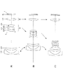
図1は、後述する実施の形態にかかるズームレンズを搭載する電子スチルカメラを示し、(a)は正面図を、(b)は背面図をそれぞれ示す。図2は、図1(a)のA−A’線に沿った断面図を示している。 1A and 1B show an electronic still camera equipped with a zoom lens according to an embodiment to be described later. FIG. 1A shows a front view and FIG. 1B shows a rear view. FIG. 2 is a cross-sectional view taken along the line A-A ′ of FIG.
図1、図2において、電子スチルカメラ1は、不図示の電源釦を押すと撮影レンズ2の不図示のシャッタが開放され撮影レンズ2で不図示の被写体からの光が集光され、像面Iに配置された撮像素子C(例えば、CCDやCMOS等)に結像される。撮像装置Cに結像された被写体像は、電子スチルカメラ1の背後に配置された液晶モニター3に表示される。撮影者は、液晶モニター3を見ながら被写体像の構図を決めた後、レリーズ釦4を押し下げ被写体像を撮像素子Cで撮影し、不図示のメモリーに記録保存する。
1 and 2, when the electronic still
撮影レンズ2は、後述する実施の形態にかかるズームレンズ2で構成されている。また、電子スチルカメラ1には、被写体が暗い場合に補助光を発光する補助光発光部5、撮影レンズ2であるレンズ系2を広角端状態(W)から望遠端状態(T)にズーミングする際のワイド(W)ーテレ(T)釦6、および電子スチルカメラ1の種々の条件設定等に使用するファンクション釦7等が配置されている。
The photographing
このようにして、後述する実施の形態にかかるズームレンズ2を内蔵する電子スチルカメラ1が構成されている。
In this way, an electronic
次に、実施の形態にかかるズームレンズに関し説明する。はじめに、実施の形態にかかるズームレンズの基本的な構造を説明する。 Next, the zoom lens according to the embodiment will be described. First, the basic structure of the zoom lens according to the embodiment will be described.
本ズームレンズは、光軸に沿って物体側から順に、負の屈折力を有する第1レンズ群と、開口絞りと、正の屈折力を有する第2レンズ群と、正の屈折力を有する第3レンズ群とを有し、広角端状態から望遠端状態への変倍に際し、前記第1レンズ群と前記第2レンズ群との間隔が減少し、前記第2レンズ群と前記第3レンズ群との間隔が増加するように、少なくとも前記第1レンズ群と前記第2レンズ群が移動し、前記第1レンズ群は、光軸に沿って物体側から順に、物体側に凸面を向けた負メニスカスレンズと、正レンズからなり、前記負メニスカスレンズの少なくとも1面は非球面であり、前記第2レンズ群は、光軸に沿って物体側から順に、第1正レンズと、第2正レンズと、負レンズと、第3正レンズからなり、前記第1正レンズの少なくとも1面は非球面であり、前記第3レンズ群は1枚の正レンズからなり、前記第3レンズ群の正レンズの少なくとも1面は非球面で構成されている。
The zoom lens includes, in order from the object side along the optical axis, a first lens group having negative refractive power, an aperture stop, a second lens group having positive refractive power, and a first lens group having positive refractive power. And a distance between the first lens group and the second lens group is reduced during zooming from the wide-angle end state to the telephoto end state, and the second lens group and the third lens group At least the first lens group and the second lens group move so that the first lens group has a negative surface with a convex surface facing the object side in order from the object side along the optical axis. The negative meniscus lens includes a meniscus lens and a positive lens, and at least one surface of the negative meniscus lens is an aspheric surface. The second lens group includes a first positive lens and a second positive lens in order from the object side along the optical axis. And a negative lens and a third positive lens, the first
以下、各レンズ群の構成と作用について説明する。 Hereinafter, the configuration and operation of each lens group will be described.
第1レンズ群は、物体の虚像を結像させると共に、変倍時には非線形に移動してズームレンズ全系の焦点位置の変動を補正する。第2レンズ群は、変倍時に単調に移動し、第1レンズ群によって作られた虚像に対して変倍を行う。第3レンズ群は、変倍中に固定または移動し、ズームレンズ全系の射出瞳位置を撮像素子に効率よく光が入射する位置にすると共に、第1レンズ群および第2レンズ群で補正しきれずに残った収差の補正を行う。 The first lens group forms a virtual image of the object and moves non-linearly at the time of zooming to correct fluctuations in the focal position of the entire zoom lens system. The second lens group moves monotonously during zooming, and zooms the virtual image created by the first lens group. The third lens group is fixed or moved during zooming, and the exit pupil position of the entire zoom lens system is set to a position where light is efficiently incident on the image pickup device, and is corrected by the first lens group and the second lens group. The remaining aberration is corrected.
また、第1レンズ群は、光軸に沿って物体側から順に、物体側に凸面を向けた負メニスカスレンズと、正レンズの2枚で構成することが望ましい。第1レンズ群を2枚のレンズで構成することにより、第1レンズ群全体の薄型化が可能となる。また、物体側から順に負屈折力・正屈折力の順にレンズを配置することにより、広角端状態における下方コマ収差と歪曲収差、望遠端状態における球面収差の補正が可能となる。 Further, it is desirable that the first lens group is composed of a negative meniscus lens having a convex surface facing the object side and a positive lens in order from the object side along the optical axis. By configuring the first lens group with two lenses, the entire first lens group can be thinned. Further, by arranging lenses in order of negative refractive power and positive refractive power from the object side, it is possible to correct downward coma and distortion in the wide-angle end state and spherical aberration in the telephoto end state.
また、第1レンズ群に含まれる負メニスカスレンズの少なくとも1面は、非球面化されていることが望ましい。非球面化によって広角端状態における歪曲収差を良好に補正できるだけでなく、第1レンズ群全体の屈折力を強めることが可能となり、コンパクト化に有利になる。なお、本発明の効果をより確実なものとするためには、負メニスカスレンズの像面側のレンズ面が非球面化されていることが望ましい。なお、第1レンズ群に含まれる正レンズは、物体側に凸面を向けたメニスカス形状であることが望ましい。正レンズを前記の形状とすることにより、広角端状態における下方コマ収差と歪曲収差、望遠端状態における球面収差を良好に補正することが可能となる。 Further, it is desirable that at least one surface of the negative meniscus lens included in the first lens group is aspherical. The aspherical surface can not only satisfactorily correct distortion at the wide-angle end state, but also can increase the refractive power of the entire first lens unit, which is advantageous for downsizing. In order to secure the effect of the present invention, it is desirable that the lens surface on the image surface side of the negative meniscus lens is aspherical. The positive lens included in the first lens group preferably has a meniscus shape with a convex surface facing the object side. By making the positive lens have the above-mentioned shape, it is possible to satisfactorily correct downward coma and distortion in the wide-angle end state and spherical aberration in the telephoto end state.
第2レンズ群の構成について説明する。負先行型のズームレンズは、全体として逆望遠型の屈折力配置となっている。単焦点レンズの場合と同様に、この屈折力配置は負の歪曲収差及び倍率色収差を発生させやすい特徴がある。従って、第2レンズ群にはこれらの収差に対して補正自由度の高いレンズタイプを採用する必要がある。 The configuration of the second lens group will be described. The negative leading zoom lens has a reverse telephoto power arrangement as a whole. As in the case of the single focus lens, this refractive power arrangement has a characteristic of easily generating negative distortion and lateral chromatic aberration. Therefore, it is necessary to adopt a lens type having a high degree of freedom in correcting these aberrations for the second lens group.
最も簡易な構成でこの条件を満たすレンズは、正屈折力・負屈折力・正屈折力の3枚のレンズからなるトリプレットである。トリプレットは、各レンズの屈折力および分散を適切に選択することにより、歪曲収差と倍率色収差を比較的自由に制御可能である。 The lens that satisfies this condition with the simplest configuration is a triplet composed of three lenses having positive refractive power, negative refractive power, and positive refractive power. The triplet can control distortion aberration and lateral chromatic aberration relatively freely by appropriately selecting the refractive power and dispersion of each lens.
しかしながら、本ズームレンズのように負の屈折力を有する第1レンズ群の後方にトリプレットからなる第2レンズ群を配置した場合、第2レンズ群には第1レンズ群によって発散された光束が入射するため、球面収差の補正が困難になり易い。また、第1レンズ群で発生する負の歪曲収差を補正する能力を高めようとするならば、第2レンズ群全体を望遠型の屈折力配置にする必要があるが、この際トリプレットの最も物体側に位置する正レンズに強い屈折力が集中するため、球面収差の補正が更に不利となる。第2レンズ群をトリプレットで構成し、球面収差を良好に補正しようとするならば、第2レンズ群全体の屈折力を弱めるほかないため、ズームレンズ全体の大型化が免れない。従って、第2レンズ群をトリプレットで構成した場合、ズームレンズ全体のコンパクト化と高性能化を両立することは困難である。 However, when the second lens group composed of a triplet is arranged behind the first lens group having negative refractive power as in this zoom lens, the light beam diverged by the first lens group is incident on the second lens group. Therefore, correction of spherical aberration tends to be difficult. In order to improve the ability to correct the negative distortion generated in the first lens group, the entire second lens group needs to have a telephoto refractive power arrangement. Since strong refractive power concentrates on the positive lens located on the side, correction of spherical aberration is further disadvantageous. If the second lens group is formed of a triplet and spherical aberration is to be corrected satisfactorily, the refractive power of the entire second lens group must be weakened. Therefore, when the second lens group is composed of triplets, it is difficult to achieve both compactness and high performance of the entire zoom lens.
上記の理由により、本ズームレンズでは、第2レンズ群の球面収差補正能力を高めるため、トリプレットの最も物体側に位置する正レンズを2枚に分割し、光軸に沿って物体側から順に第1正レンズと、第2正レンズと、負レンズと、第3正レンズの4枚のレンズで第2レンズ群を構成することが望ましい。これにより歪曲収差や倍率色収差の補正能力が向上するとともに、第2レンズ群全体の屈折力を強めることができ、ズームレンズ全体のコンパクト化が可能となる。 For the above reasons, in this zoom lens, in order to improve the spherical aberration correction capability of the second lens group, the positive lens located closest to the object side of the triplet is divided into two pieces, and the first lens is sequentially arranged from the object side along the optical axis. It is desirable that the second lens group is composed of four lenses: a first positive lens, a second positive lens, a negative lens, and a third positive lens. As a result, the correction capability of distortion aberration and lateral chromatic aberration can be improved, the refractive power of the entire second lens group can be increased, and the entire zoom lens can be made compact.
また、第2レンズ群に含まれる第1正レンズの少なくとも1面が非球面化されていることが望ましい。非球面を用いることにより、第2レンズ群で発生する球面収差を更に良好に補正可能となるだけでなく、第2レンズ群全体の屈折力を強めることが可能となり、ズームレンズ全体のコンパクト化に有利となる。なお、本発明の効果をより確実なものとするためには、第1正レンズの物体側の面が非球面化されていることが望ましい。また、第1正レンズの両側のレンズ面を非球面化することにより、球面収差およびコマ収差の補正能力を更に高めることも可能である。 In addition, it is desirable that at least one surface of the first positive lens included in the second lens group is aspherical. By using an aspherical surface, not only the spherical aberration generated in the second lens group can be corrected more satisfactorily, but also the refractive power of the entire second lens group can be increased, thereby making the entire zoom lens compact. It will be advantageous. In order to secure the effect of the present invention, it is desirable that the object-side surface of the first positive lens is aspherical. In addition, it is possible to further improve the correction capability of spherical aberration and coma aberration by making the lens surfaces on both sides of the first positive lens aspherical.
第3レンズ群は、一枚の正レンズで構成されていることが望ましい。第3レンズ群を一枚のレンズで構成することにより、沈胴収納時の厚みを減らすことが可能となる。さらに第3レンズ群に含まれる各レンズ面の少なくとも1面が非球面化されていることが望ましい。第3レンズ群に非球面を使用することにより、第1レンズ群および第2レンズ群で補正しきれなかった非点収差の効果的な補正が可能になる。 The third lens group is preferably composed of one positive lens. By configuring the third lens group with a single lens, it is possible to reduce the thickness when retracted. Furthermore, it is desirable that at least one of the lens surfaces included in the third lens group be aspherical. By using an aspheric surface for the third lens group, it is possible to effectively correct astigmatism that cannot be corrected by the first lens group and the second lens group.
また、本ズームレンズは、以下の条件式(1)から(3)を満足することが望ましい。
(1) 0.50 < ft×Ymax / {fw×(fw+ft)} < 0.70
(2) 0.114 < fw / TL < 0.145
(3) 1.14 < |f1|/(fw×ft)1/2 < 1.35
但し、Ymax はズームレンズの最大像高、fwは広角端状態におけるズームレンズ全系の焦点距離、ftは望遠端状態におけるズームレンズ全系の焦点距離、TLはズームレンズの最大全長、f1は第1レンズ群の焦点距離である。
In addition, it is desirable that the zoom lens satisfies the following conditional expressions (1) to (3).
(1) 0.50 <ft × Ymax / {fw × (fw + ft)} <0.70
(2) 0.114 <fw / TL <0.145
(3) 1.14 <| f1 | / (fw × ft) 1/2 <1.35
Where Ymax is the maximum image height of the zoom lens, fw is the focal length of the entire zoom lens system at the wide-angle end state, ft is the focal length of the entire zoom lens system at the telephoto end state, TL is the maximum total length of the zoom lens, and f1 is the first total length. This is the focal length of one lens group.
条件式(1)は、広角端状態におけるズームレンズ全系の焦点距離と、望遠端状態におけるズームレンズ全系の焦点距離、最大像高について適切な範囲を規定している。条件式(1)の下限値を下回ると、広角端状態において十分な画角を確保することが不可能となるか、十分な変倍比を確保することが困難となる。従って本発明の目的であるズームレンズの広角化および高変倍化に反するので好ましくない。条件式(1)の上限値を上回ると、広角端状態における画角が広くなり過ぎ、歪曲収差の補正が困難になるだけでなく、望遠端状態における焦点距離が長くなりすぎるため、球面収差の補正が困難となる。従って良好な光学性能を維持することが困難となるため好ましくない。 Conditional expression (1) defines an appropriate range for the focal length of the entire zoom lens system in the wide-angle end state, the focal length of the entire zoom lens system in the telephoto end state, and the maximum image height. If the lower limit of conditional expression (1) is not reached, it becomes impossible to ensure a sufficient angle of view in the wide-angle end state, or it becomes difficult to ensure a sufficient zoom ratio. Therefore, it is not preferable because it is contrary to the wide angle and high zoom ratio of the zoom lens which is the object of the present invention. If the upper limit value of conditional expression (1) is exceeded, the angle of view at the wide-angle end state becomes too wide, making it difficult to correct distortion, and the focal length at the telephoto end state becomes too long. Correction becomes difficult. Accordingly, it is difficult to maintain good optical performance, which is not preferable.
なお、本発明の効果を確実にするために、条件式(1)の下限値を0.54にすることが好ましい。また、本発明の効果を更に確実にするために、条件式(1)下限値を0.56にすることが更に好ましい。また、本発明の効果を確実にするために、条件式(1)の上限値を0.65にすることが好ましい。また、本発明の効果を更に確実にするために、条件式(1)の上限値を0.62にすることが更に好ましい。 In order to secure the effect of the present invention, it is preferable to set the lower limit of conditional expression (1) to 0.54. In order to further secure the effect of the present invention, it is more preferable to set the lower limit of conditional expression (1) to 0.56. In order to secure the effect of the present invention, it is preferable to set the upper limit of conditional expression (1) to 0.65. In order to further secure the effect of the present invention, it is more preferable to set the upper limit of conditional expression (1) to 0.62.
条件式(2)は、広角端状態におけるズームレンズ全系の焦点距離と、ズームレンズ全系の最大全長の適切な範囲を規定している。条件式(2)の下限値を下回った場合、ズームレンズ全系の最大全長が長くなりすぎ、ズームレンズのコンパクト化という本発明の目的に反するので好ましくない。また。望遠端状態における倍率色収差ぼ補正が困難となる。条件式(2)の上限値を上回った場合、各レンズ群の屈折力が著しく強くなるため、良好な球面収差補正が困難となり好ましくない。 Conditional expression (2) defines an appropriate range of the focal length of the entire zoom lens system in the wide-angle end state and the maximum total length of the entire zoom lens system. If the lower limit value of conditional expression (2) is not reached, the maximum total length of the entire zoom lens system becomes too long, which is against the object of the present invention of making the zoom lens compact. Also. It becomes difficult to correct the lateral chromatic aberration in the telephoto end state. If the upper limit value of conditional expression (2) is exceeded, the refractive power of each lens group becomes remarkably strong, making it difficult to correct spherical aberration, which is not preferable.
なお、本発明の効果を確実にするために、条件式(2)の下限値を0.117にすることが好ましい。また、本発明の効果を更に確実にするために、条件式(2)下限値を0.120にすることが更に好ましい。また、本発明の効果を確実にするために、条件式(2)の上限値を0.135にすることが好ましい。また、本発明の効果を更に確実にするために、条件式(2)の上限値を0.130にすることが更に好ましい。 In order to secure the effect of the present invention, it is preferable to set the lower limit of conditional expression (2) to 0.117. In order to further secure the effect of the present invention, it is more preferable to set the lower limit of conditional expression (2) to 0.120. In order to secure the effect of the present invention, it is preferable to set the upper limit of conditional expression (2) to 0.135. In order to further secure the effect of the present invention, it is more preferable to set the upper limit of conditional expression (2) to 0.130.
条件式(3)は、第1レンズ群の焦点距離と、広角端状態におけるズームレンズ全系の焦点距離、望遠端状態におけるズームレンズ全系の焦点距離に関して適切な範囲を規定している。条件式(3)の下限値を下回った場合、望遠端状態においてズームレンズの全長が著しく長くなる。また、広角端状態における下方コマ収差や歪曲収差、望遠端状態における球面収差や下方コマ収差の補正が困難になるため好ましくない。条件式(3)の上限値を上回った場合、広角端状態においてズームレンズの全長が著しく長くなるとともに、第1レンズ群の最も物体側に位置する負メニスカスレンズの外径が増大する。負メニスカスレンズの外径を小型化するためには第1レンズ群を構成する各レンズの屈折力を著しく強めることが不可欠となるが、このような手段では広角端状態における下方コマ収差、望遠端状態における球面収差の補正が困難となるため好ましくない。 Conditional expression (3) defines appropriate ranges for the focal length of the first lens group, the focal length of the entire zoom lens system in the wide-angle end state, and the focal length of the entire zoom lens system in the telephoto end state. When the lower limit value of conditional expression (3) is not reached, the total length of the zoom lens is significantly increased in the telephoto end state. Further, it is not preferable because it is difficult to correct the lower coma aberration and distortion in the wide-angle end state, and the spherical aberration and lower coma aberration in the telephoto end state. When the upper limit value of conditional expression (3) is exceeded, the overall length of the zoom lens becomes significantly longer in the wide-angle end state, and the outer diameter of the negative meniscus lens located closest to the object side in the first lens group increases. In order to reduce the outer diameter of the negative meniscus lens, it is indispensable to remarkably increase the refractive power of each lens constituting the first lens group. However, with such means, lower coma aberration at the wide-angle end state, telephoto end This is not preferable because correction of spherical aberration in the state becomes difficult.
なお、本発明の効果を確実にするために、条件式(3)の下限値を1.18にすることが好ましい。また、本発明の効果を更に確実にするために、条件式(3)下限値を1.20にすることが更に好ましい。また、本発明の効果を確実にするために、条件式(3)の上限値を1.35にすることが好ましい。また、本発明の効果を更に確実にするために、条件式(3)の上限値を1.30にすることが更に好ましい。 In order to secure the effect of the present invention, it is preferable to set the lower limit of conditional expression (3) to 1.18. In order to further secure the effect of the present invention, it is more preferable to set the lower limit of conditional expression (3) to 1.20. In order to secure the effect of the present invention, it is preferable to set the upper limit of conditional expression (3) to 1.35. In order to further secure the effect of the present invention, it is more preferable to set the upper limit of conditional expression (3) to 1.30.
また、本ズームレンズでは、フォーカシング時に第3レンズ群が単独で光軸に沿って物体側に移動し、遠距離物体から近距離物体へのフォーカシングを行う構成が望ましい。第3レンズ群をフオーカシングに用いることにより、画面周辺部に到達する光量を減少させずに、広角端状態での至近距離物体の撮影を行うことが可能である。なお、負先行型ズームでは、負の屈折力を有する第1レンズ群を用いてフオーカシングを行うことも可能であるが、広角端状態における至近距離物体の撮影時に、画面周辺部に到達する光量が著しく減少する問題がある。これを防ぐには第1レンズ群の外径を増大させる必要が生じるが、広角端状態における下方コマ収差の補正が困難となるため好ましくない。 In the zoom lens, it is desirable that the third lens unit independently moves to the object side along the optical axis during focusing to perform focusing from a long-distance object to a short-distance object. By using the third lens group for focusing, it is possible to shoot an object at a close distance in the wide-angle end state without reducing the amount of light reaching the periphery of the screen. In the negative leading zoom, focusing can be performed using the first lens unit having a negative refractive power, but the amount of light reaching the periphery of the screen at the time of photographing a very close object in the wide-angle end state is small. There is a problem of significant reduction. To prevent this, it is necessary to increase the outer diameter of the first lens group, but it is not preferable because it is difficult to correct the lower coma aberration in the wide-angle end state.
また、本ズームレンズは、以下の条件式(4)を満足することが望ましい。
(4) −0.20 < (Rb+Ra)/(Rb−Ra) < 1.50
但し、Raは第3レンズ群の正レンズの物体側の面の近軸曲率半径、Rbは第3レンズ群の正レンズの像面側の面の近軸曲率半径である。
In addition, it is desirable that the zoom lens satisfies the following conditional expression (4).
(4) -0.20 <(Rb + Ra) / (Rb-Ra) <1.50
Where Ra is the paraxial radius of curvature of the object side surface of the positive lens in the third lens group, and Rb is the paraxial radius of curvature of the image side surface of the positive lens in the third lens group.
条件式(4)は第3レンズ群を構成する正レンズの形状に関して適切な範囲を規定している。本ズームレンズのように広角域を包括する負先行型ズームレンズでは、一般に広角端状態において、第1レンズ群内で歪曲収差と非点収差の両方を同時に補正することが困難である。そのため、第1レンズ群では負の歪曲収差の補正を重点的に行い、その結果残存した非点収差を第3レンズ群で補正する収差構造にする必要がある。しかしながら、第3レンズ群の正レンズの形状が不適切な場合、正レンズから発生する負の歪曲収差が増大し補正が困難となる。 Conditional expression (4) defines an appropriate range for the shape of the positive lens constituting the third lens group. In a negative advanced zoom lens including a wide-angle region, such as this zoom lens, it is generally difficult to correct both distortion and astigmatism in the first lens group at the wide-angle end state. Therefore, it is necessary to make an aberration structure in which the first lens group focuses on correcting the negative distortion and the astigmatism remaining as a result is corrected by the third lens group. However, when the shape of the positive lens of the third lens group is inappropriate, the negative distortion generated from the positive lens increases and correction becomes difficult.
また後述するように、第3レンズ群をフォーカシングに使用する場合、撮影距離によって第3レンズ群の正レンズを通過する主光線高が変化するため、第3レンズ群の正レンズの形状が不適切な場合はフォーカシングによる収差変動が発生し易い。上記の理由により、第3レンズ群を構成する正レンズの形状には、広角端状態における歪曲収差および非点隔差の良好な補正が可能であり、かつフォーカシングによる収差変動が最小となる範囲が存在する。 As will be described later, when the third lens group is used for focusing, the height of the principal ray passing through the positive lens of the third lens group varies depending on the shooting distance, so the shape of the positive lens of the third lens group is inappropriate. In this case, aberration fluctuations due to focusing are likely to occur. For the above reasons, there is a range in which the positive lens constituting the third lens group can correct distortion and astigmatism in the wide-angle end state and minimize aberration fluctuations due to focusing. To do.
条件式(4)の下限値を下回った場合、至近距離物体の撮影時にすべての焦点距離状態において像面が著しく正に変動し、さらに非点収差が増大するため好ましくない。条件式(4)の上限値を上回った場合、広角端状態において第3レンズ群の正レンズで発生する負の歪曲収差が増大し、これを第1レンズ群で補正しようとすると、広角端状態における下方コマ収差の補正が困難になるため好ましくない。また第3レンズ群の正レンズの像面側の面がゴーストの発生原因となるため好ましくない。 If the lower limit value of conditional expression (4) is not reached, it is not preferable because the image plane fluctuates positively in all focal length states and astigmatism increases when photographing a close object. If the upper limit value of conditional expression (4) is exceeded, negative distortion occurring in the positive lens of the third lens group increases in the wide-angle end state. If this is corrected by the first lens group, the wide-angle end state This is not preferable because it is difficult to correct the lower coma aberration. Further, the image side surface of the positive lens in the third lens group is not preferable because it causes ghosting.
なお、本発明の効果を確実にするために、条件式(4)の下限値を0.00にすることが好ましい。また、本発明の効果を確実にするために、条件式(4)の上限値を1.00にすることが好ましい。 In order to secure the effect of the present invention, it is preferable to set the lower limit of conditional expression (4) to 0.00. In order to secure the effect of the present invention, it is preferable to set the upper limit of conditional expression (4) to 1.00.
また、本ズームレンズは、以下の条件式(5)を満足することが望ましい。
(5) 80.0 < ν31 < 95.0
但し、ν31は第3レンズ群の正レンズ材質のd線(波長λ=587.6nm)に対するアッベ数である。
In addition, it is desirable that the zoom lens satisfies the following conditional expression (5).
(5) 80.0 <ν31 <95.0
Where ν31 is the Abbe number with respect to the d-line (wavelength λ = 587.6 nm) of the positive lens material of the third lens group.
条件式(5)は、第3レンズ群の正レンズのアッベ数に関して、適切な範囲を規定している。前述したとおり第3レンズ群をフォーカシングに使用する場合、撮影距離によって第3レンズ群の正レンズを通過する主光線高が変化する。従って第3レンズ群の正レンズのアッベ数が不適切な場合、フォーカシングによる倍率色収差の変動が生じやすい。条件式(5)の下限値を下回った場合、望遠端状態状態における倍率色収差の補正が困難となる。至近距離物体撮影時の倍率色収差の変動が増大するため好ましくない。条件式(5)の上限値を上回った場合、望遠端状態における倍率色収差が補正過剰となるため好ましくない。また、既存の光学材料を用いる場合第3レンズ群の正レンズに蛍石を使用する必要が生じるが、蛍石は非球面加工が困難なため好ましくない。 Conditional expression (5) defines an appropriate range for the Abbe number of the positive lens in the third lens group. As described above, when the third lens group is used for focusing, the height of the principal ray passing through the positive lens of the third lens group varies depending on the shooting distance. Therefore, when the Abbe number of the positive lens in the third lens group is inappropriate, the lateral chromatic aberration is likely to change due to focusing. If the lower limit of conditional expression (5) is not reached, it will be difficult to correct lateral chromatic aberration in the telephoto end state. This is not preferable because the variation in lateral chromatic aberration during close-up object photography increases. Exceeding the upper limit value of conditional expression (5) is not preferable because lateral chromatic aberration in the telephoto end state becomes excessively corrected. In addition, when an existing optical material is used, it is necessary to use fluorite for the positive lens of the third lens group. However, fluorite is not preferable because aspherical processing is difficult.
また、本ズームレンズは、以下の条件式(6)を満足することが望ましい。
(6) 0.55 < fL11 / f1 < 0.65
但し、fL11は第1レンズ群の負メニスカスレンズの焦点距離である。
In addition, it is desirable that the zoom lens satisfies the following conditional expression (6).
(6) 0.55 <fL11 / f1 <0.65
Here, fL11 is the focal length of the negative meniscus lens of the first lens group.
条件式(6)は第1レンズ群の焦点距離と、第1レンズ群の負メニスカスレンズの焦点距離に関して適切な範囲を規定している。条件式(6)の下限値を下回った場合、広角端状態における下方コマ収差の補正が困難となるため好ましくない。条件式(6)の上限値を上回った場合、第1レンズ群の負メニスカスレンズと正レンズとの軸上空気間隔が広くなるため第1レンズ群の総厚が増大し、ズームレンズのコンパクト化という本発明の目的に反するため好ましくない。また、広角端状態における非点収差の補正が困難となるため好ましくない。 Conditional expression (6) defines an appropriate range for the focal length of the first lens group and the focal length of the negative meniscus lens of the first lens group. When the value falls below the lower limit value of conditional expression (6), it is difficult to correct downward coma in the wide-angle end state, which is not preferable. When the upper limit value of conditional expression (6) is exceeded, the axial air space between the negative meniscus lens and the positive lens in the first lens group becomes wide, so the total thickness of the first lens group increases and the zoom lens becomes compact. This is contrary to the object of the present invention. Further, it is not preferable because correction of astigmatism in the wide-angle end state becomes difficult.
なお、本発明の効果を確実にするために、条件式(6)の下限値を0.56にすることが好ましい。また、本発明の効果を確実にするために、条件式(6)の上限値を0.63にすることが好ましい。 In order to secure the effect of the present invention, it is preferable to set the lower limit of conditional expression (6) to 0.56. In order to secure the effect of the present invention, it is preferable to set the upper limit of conditional expression (6) to 0.63.
また、本ズームレンズは、以下の条件式(7)、(8)を満足することが望ましい。
(7) 0.29 < n23 − n24 < 0.50
(8) 25.0 < ν23
但し、n23は第2レンズ群の負レンズの材質のd線(λ=587.6nm)に対する屈折率、n24は第2レンズ群の第3正レンズの材質のd線(λ=587.6nm)に対する屈折率、ν23は第2レンズ群の負レンズの材質のd線(λ=587.6nm)に対するアッベ数である。
In addition, it is desirable that the zoom lens satisfies the following conditional expressions (7) and (8).
(7) 0.29 <n23-n24 <0.50
(8) 25.0 <ν23
However, n23 is the refractive index with respect to the d-line (λ = 587.6 nm) of the negative lens material of the second lens group, and n24 is the d-line (λ = 587.6 nm) of the third positive lens material of the second lens group. The refractive index ν23 is the Abbe number for the d-line (λ = 587.6 nm) of the material of the negative lens in the second lens group.
条件式(7)は第2レンズ群の負レンズと第2レンズ群の第3正レンズの屈折率差に関して適切な範囲を規定している。条件式(7)の下限値を下回った場合、広角端状態における非点収差の補正が困難となるため好ましくない。条件式(7)の上限値を上回った場合、ペッツバール和が著しく正になり、望遠端状態において非点収差と像面湾曲を同時に補正することが困難となるため好ましくない。 Conditional expression (7) defines an appropriate range for the difference in refractive index between the negative lens of the second lens group and the third positive lens of the second lens group. If the lower limit value of conditional expression (7) is not reached, correction of astigmatism in the wide-angle end state becomes difficult, which is not preferable. If the upper limit value of conditional expression (7) is exceeded, the Petzval sum becomes extremely positive, and it becomes difficult to correct astigmatism and curvature of field simultaneously in the telephoto end state.
なお、本発明の効果を確実にするために、条件式(7)の下限値を0.33にすることが好ましい。また、本発明の効果を更に確実にするために、条件式(7)下限値を0.35にすることが更に好ましい。 In order to secure the effect of the present invention, it is preferable to set the lower limit of conditional expression (7) to 0.33. In order to further secure the effect of the present invention, it is more preferable to set the lower limit of conditional expression (7) to 0.35.
条件式(8)は第2レンズ群の負レンズのアッベ数に関して適切な範囲を規定している。条件式(8)の下限値を下回った場合、負レンズの部分分散比が増大するため、望遠端状態における軸上色収差の二次スペクトルが増大する。従って高い光学性能を発揮することが困難となるため好ましくない。 Conditional expression (8) defines an appropriate range for the Abbe number of the negative lens of the second lens group. When the lower limit value of conditional expression (8) is not reached, the partial dispersion ratio of the negative lens increases, so that the secondary spectrum of axial chromatic aberration in the telephoto end state increases. Therefore, it is not preferable because it is difficult to exhibit high optical performance.
なお、本発明の効果を確実にするために、条件式(8)の下限値を27.0にすることが好ましい。 In order to secure the effect of the present invention, it is preferable to set the lower limit of conditional expression (8) to 27.0.
また、本ズームレンズは、第2レンズ群の第2正レンズと第2レンズ群の負レンズは互いに接合されていることが望ましい。 In the zoom lens, it is preferable that the second positive lens of the second lens group and the negative lens of the second lens group are cemented with each other.
第2レンズ群に含まれるレンズのうち、第2正レンズと負レンズとが接合されていることにより、該レンズの偏芯に対する誤差感度を大幅に緩和可能となる。 Since the second positive lens and the negative lens among the lenses included in the second lens group are cemented, the error sensitivity with respect to the eccentricity of the lens can be relieved greatly.
また、本ズームレンズは、、以下の条件式(9)を満足することが望ましい。
(9) 0.30 < Rc / Rd < 1.10
但し、Rcは前記第2レンズ群の第1正レンズの物体側の面の近軸曲率半径、Rdは前記第2レンズ群の第2正レンズの物体側の面の近軸曲率半径である。
In addition, it is desirable that the zoom lens satisfies the following conditional expression (9).
(9) 0.30 <Rc / Rd <1.10
Where Rc is the paraxial radius of curvature of the object side surface of the first positive lens of the second lens group, and Rd is the paraxial radius of curvature of the object side surface of the second positive lens of the second lens group.
条件式(9)は第2レンズ群の第1正レンズと第2正レンズの形状に関して適切な範囲を規定している。条件式(9)の下限値を下回ると、広角端状態における歪曲収差の補正が困難となり、これを第3レンズ群で補正しようとすると、望遠端状態において至近距離物体撮影時の非点収差が増大するため好ましくない。条件式(9)の上限値を上回ると、広角端状態および中間焦点距離状態における球面収差が補正不足となるのに加え、上方コマ収差の波長による差が増大する。また第2レンズ群の第2正レンズおよび第2レンズ群の負レンズの中心厚公差が厳しくなり、これを緩和するためには第2レンズ群の第2正レンズおよび第2レンズ群の負レンズの中心厚を厚くしなければならないため、第2レンズ群全体が大型化し好ましくない。 Conditional expression (9) defines an appropriate range for the shapes of the first positive lens and the second positive lens of the second lens group. If the lower limit of conditional expression (9) is not reached, it will be difficult to correct distortion at the wide-angle end state, and if this is attempted to be corrected by the third lens group, astigmatism during close-up object shooting will occur at the telephoto end state. Since it increases, it is not preferable. If the upper limit value of conditional expression (9) is exceeded, spherical aberration in the wide-angle end state and the intermediate focal length state becomes insufficiently corrected, and the difference due to the wavelength of the upper coma aberration increases. Further, the center thickness tolerance of the second positive lens of the second lens group and the negative lens of the second lens group becomes strict, and in order to alleviate this, the second positive lens of the second lens group and the negative lens of the second lens group Since the center thickness of the second lens group must be increased, the entire second lens group is undesirably large.
なお、本発明の効果を確実にするために、条件式(9)の下限値を0.35にすることが好ましい。また、本発明の効果を更に確実にするために、条件式(9)下限値を0.40にすることが更に好ましい。また、本発明の効果を確実にするために、条件式(9)の上限値を0.80にすることが好ましい。また、本発明の効果を更に確実にするために、条件式(9)の上限値を0.75にすることが更に好ましい。 In order to secure the effect of the present invention, it is preferable to set the lower limit of conditional expression (9) to 0.35. In order to further secure the effect of the present invention, it is more preferable to set the lower limit of conditional expression (9) to 0.40. In order to secure the effect of the present invention, it is preferable to set the upper limit of conditional expression (9) to 0.80. In order to further secure the effect of the present invention, it is more preferable to set the upper limit of conditional expression (9) to 0.75.
また、本ズームレンズは、第1レンズ群の正レンズの少なくとも1面は非球面であることが望ましい。このように非球面を導入することでズームレンズを薄型化する事ができる。非球面化により、負メニスカスレンズと正レンズとの空気間隔を狭めた場合にも、広角端状態における像面湾曲と下方コマ収差を良好に補正することが可能となり、第1レンズ群の薄型化が可能となる。なお、本発明の効果をより確実なものとするためには、正レンズの物体側のレンズ面が非球面化されていることが望ましい。 In the zoom lens, it is preferable that at least one surface of the positive lens in the first lens group is an aspherical surface. By introducing an aspherical surface in this way, the zoom lens can be thinned. Even if the air space between the negative meniscus lens and the positive lens is narrowed by aspherical surface, it becomes possible to satisfactorily correct the curvature of field and the lower coma in the wide-angle end state, and the first lens unit can be made thinner. Is possible. In order to secure the effect of the present invention, it is desirable that the lens surface on the object side of the positive lens be aspherical.
また、本ズームレンズは、第3レンズ群の正レンズの物体側の面が非球面であり、かつ該非球面は光軸付近に比べ、レンズ周辺部の方が正の屈折力が強くなる形状であることが望ましい。これにより望達端状態における像面湾曲を良好に補正できるとともに、至近撮影時の像面湾曲、非点収差の変動を良好に補正することが出来る。 In the zoom lens, the object-side surface of the positive lens in the third lens group is an aspheric surface, and the aspheric surface has a shape in which the positive refractive power is stronger at the lens periphery than at the optical axis. It is desirable to be. Thereby, it is possible to satisfactorily correct the field curvature in the telephoto end state, and it is possible to satisfactorily correct the field curvature and astigmatism variation during close-up photography.
また、本ズームレンズでは、第3レンズ群は変倍に際して固定されていることが好ましい。変倍に際して第3レンズ群の位置を固定することにより、第3レンズ群の偏芯による非点収差の増大を防ぐことが出来る。 In the zoom lens, it is preferable that the third lens group is fixed during zooming. By fixing the position of the third lens group at the time of zooming, it is possible to prevent an increase in astigmatism due to the eccentricity of the third lens group.
なお、本ズームレンズにおいて、該ズームレンズを構成する各レンズ群のうち、1つのレンズ群全体又はその一部のレンズを光軸と略垂直な方向に移動させる構成とすることもできる。これにより、像面上の像を移動させることが可能となり、いわゆる防振レンズを実現することができる。 In the zoom lens, among the lens groups constituting the zoom lens, one lens group or a part of the lens group may be moved in a direction substantially perpendicular to the optical axis. Thereby, it is possible to move the image on the image plane, and it is possible to realize a so-called anti-vibration lens.
(実施例)
以下、本発明の実施の形態にかかるズームレンズの各実施例について図面を参照しつつ説明する。
(Example)
Embodiments of the zoom lens according to the embodiment of the present invention will be described below with reference to the drawings.
(第1実施例)
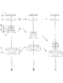
図3は、第1実施例にかかるズームレンズのレンズ構成を示す図である。
(First Example)
FIG. 3 is a diagram illustrating a lens configuration of the zoom lens according to the first example.
図3において、本第1実施例にかかるズームレンズは、光軸に沿って物体側から順に、負の屈折力を有する第1レンズ群G1と、開口絞りSと、正の屈折力を有する第2レンズ群G2と、正の屈折力を有する第3レンズ群G3とを有し、広角端状態Wから望遠端状態Tへの変倍に際し、第1レンズ群G1と第2レンズ群G2との間隔が減少し、第2レンズ群G2と第3レンズ群G3との間隔が増加するように、第1レンズ群G1と第2レンズ群G2が移動し、第3レンズ群G3が固定された構成である。 In FIG. 3, the zoom lens according to the first example includes, in order from the object side along the optical axis, a first lens group G1 having a negative refractive power, an aperture stop S, and a first lens having a positive refractive power. A second lens group G2 and a third lens group G3 having a positive refractive power, and at the time of zooming from the wide-angle end state W to the telephoto end state T, the first lens group G1 and the second lens group G2 A configuration in which the first lens group G1 and the second lens group G2 are moved and the third lens group G3 is fixed so that the distance is decreased and the distance between the second lens group G2 and the third lens group G3 is increased. It is.
第1レンズ群G1は、光軸に沿って物体側から順に、物体側に凸面を向けた負メニスカスレンズL11、物体側に凸面を向けた正メニスカスレンズL12とから構成され、負メニスカスレンズL11の像面I側のレンズ面、および正メニスカスレンズL12の物体側のレンズ面は非球面で構成されている。 The first lens group G1 includes, in order from the object side along the optical axis, a negative meniscus lens L11 having a convex surface directed toward the object side, and a positive meniscus lens L12 having a convex surface directed toward the object side. The lens surface on the image plane I side and the lens surface on the object side of the positive meniscus lens L12 are aspherical.
第2レンズ群G2は、光軸に沿って物体側から順に、第1正レンズL21、第2正レンズL22、負レンズL23、第3正レンズL24とから構成され、第2正レンズL22と負レンズL23とは接合されており、第1正レンズL21の物体側の面が非球面で構成されている。 The second lens group G2 includes, in order from the object side along the optical axis, a first positive lens L21, a second positive lens L22, a negative lens L23, and a third positive lens L24, and is negative with the second positive lens L22. The lens L23 is cemented, and the object-side surface of the first positive lens L21 is an aspherical surface.
第3レンズ群G3は1枚の正レンズL31のみからなり、正レンズL31の物体側の面が非球面で構成されている。 The third lens group G3 includes only one positive lens L31, and the object-side surface of the positive lens L31 is aspheric.
また、無限遠物体から有限距離物体へのフォーカシングは、第3レンズ群G3を光軸に沿って物体方向に移動させることによって行う。 Further, focusing from an infinitely distant object to a finite distance object is performed by moving the third lens group G3 along the optical axis in the object direction.
開口絞りSは、第2レンズ群G2の最も物体側の第1正レンズL21より物体側に配置されており、広角端状態Wから望遠端状態Tへの変倍に際し、第2レンズ群G2と一体的に移動する。 The aperture stop S is disposed closer to the object side than the first positive lens L21 closest to the object side in the second lens group G2, and when changing from the wide-angle end state W to the telephoto end state T, the aperture stop S and the second lens group G2 Move together.
また、フィルタ群FLは、赤外カットフィルタなどで構成されている。 The filter group FL is configured by an infrared cut filter or the like.
以下の表1に、本第1実施例にかかるズームレンズの諸元の値を掲載する。[全体諸元]中のfは焦点距離、FNOはFナンバー、2ωは画角、Ymaxは最大像高をそれぞれ示している。[レンズ諸元]において、第1カラムは物体側から数えた際のレンズ面の番号、第2カラムrはレンズ面の曲率半径、第3カラムdはレンズ面の光軸上の間隔、第4カラムνdはd線(波長λ=587.6nm)に対するアッベ数、第5カラムndはd線(波長λ=587.6nm)に対する屈折率をそれぞれ示している。なお、第1カラムの左に付した*は、そのレンズ面が非球面であることを示している。B.f.はバックフォーカスである。また、空気の屈折率は1.000000であるが、表中においてはこの表記を省略している。曲率半径r欄の「∞」は平面であることを示す。 Table 1 below provides values of specifications of the zoom lens according to the first example. In [Overall Specifications], f represents a focal length, FNO represents an F number, 2ω represents an angle of view, and Ymax represents a maximum image height. In [lens specifications], the first column is the lens surface number when counted from the object side, the second column r is the radius of curvature of the lens surface, the third column d is the distance on the optical axis of the lens surface, and the fourth Column νd indicates the Abbe number with respect to d-line (wavelength λ = 587.6 nm), and fifth column nd indicates the refractive index with respect to d-line (wavelength λ = 587.6 nm). In addition, * attached | subjected to the left of the 1st column has shown that the lens surface is an aspherical surface. B.f. is back focus. Moreover, although the refractive index of air is 1.000000, this notation is omitted in the table. “∞” in the radius of curvature r column indicates a plane.
非球面は、光軸に垂直な方向の高さをy、高さyにおける各非球面の頂点の接平面から各非球面までの光軸に沿った距離(サグ量)をS(y)、基準球面の曲率半径(近軸曲率半径)をR、円錐定数をκ、n次の非球面係数をCnとしたとき、以下の数式で表される。
S(y)=(y2/R)/{1+(1−κy2/R2)1/2}
+C4y4+C6y6+C8y8+C10y10
[可変間隔データ]には、広角端状態、中間焦点距離状態、望遠端状態の各状態での焦点距離f、撮影倍率β、物体から最も物体側のレンズ面までの距離D0、各可変間隔の値を示す。また、非球面データ欄の「E−n」(nは整数)は「×10-n」を示す。[条件式対応数値]には、各条件式の対応値を示す。
The aspherical surface has a height in the direction perpendicular to the optical axis as y, a distance (sag amount) along the optical axis from the tangent plane of each aspherical vertex at the height y to each aspherical surface as S (y), When the radius of curvature of the reference spherical surface (paraxial radius of curvature) is R, the conic constant is κ, and the nth-order aspherical coefficient is Cn, the following formula is used.
S (y) = (y 2 / R) / {1+ (1-κy 2 / R 2 ) 1/2 }
+ C4y 4 + C6y 6 + C8y 8 + C10y 10
In [variable interval data], the focal length f in each of the wide-angle end state, the intermediate focal length state, and the telephoto end state, the photographing magnification β, the distance D0 from the object to the lens surface closest to the object, and the variable intervals Indicates the value. In addition, “En” (n is an integer) in the aspherical data column indicates “× 10 −n ”. [Conditional Expression Corresponding Value] shows the corresponding value of each conditional expression.
なお、以下の全ての諸元値において、掲載されている焦点距離f、曲率半径r、面間隔dその他の長さ等は、特記の無い場合一般に「mm」が使われるが、光学系は比例拡大または比例縮小しても同等の光学性能が得られるので、これに限られるものではない。また、単位は「mm」に限定されること無く他の適当な単位を用いることもできる。さらに、これらの記号の説明は、以降の他の実施例においても同様とし説明を省略する。 In all the following specification values, “mm” is generally used as the focal length f, radius of curvature r, surface interval d and other lengths, etc. unless otherwise specified, but the optical system is proportional. Even if it is enlarged or proportionally reduced, the same optical performance can be obtained. Further, the unit is not limited to “mm”, and other appropriate units may be used. Further, the explanation of these symbols is the same in the other embodiments, and the explanation is omitted.
(表1)
[全体諸元]
f=4.81〜16.50
FNO=2.86〜5.62
2ω=77.4°〜24.7°
Ymax = 3.60
[レンズ諸元]
r d νd nd
1) 62.0000 1.1000 42.71 1.820800
*2) 4.8023 2.6500
*3) 11.7856 1.7500 21.15 1.906800
4) 31.9452 (d4)
5) ∞ 0.4000 開口絞りS
*6) 5.8388 1.6500 53.22 1.693500
7) -369.0030 0.3000
8) 9.3983 1.7000 46.63 1.816000
9) -10.1776 0.6000 31.31 1.903660
10) 4.2031 0.7000
11) 13.9065 1.3000 52.32 1.517420
12) -20.0955 (d12)
*13) 13.5095 1.7000 82.56 1.497820
14) -95.5633 (d14)
15) ∞ 0.5000 64.12 1.516800
16) ∞ (B.f.)
[非球面データ]
(第2面)
κ = 0.1500
C4 = 2.47630E-04
C6 = 5.17320E-06
C8 = -1.68170E-07
C10= 1.85430E-09
(第3面)
κ = 1.8300
C4 = 2.66010E-05
C6 = 0.00000E+00
C8 = 0.00000E+00
C10= 0.00000E+00
(第6面)
κ = 0.4325
C4 = -4.14000E-05
C6 = 0.00000E+00
C8 = 0.00000E+00
C10= 0.00000E+00
(第13面)
κ = 2.7400
C4 = -8.77120E-05
C6 = 0.00000E+00
C8 = 0.00000E+00
C10= 0.00000E+00
[可変間隔データ]
広角端状態 中間焦点距離状態 望遠端状態
f 4.81 8.80 16.50
D0 ∞ ∞ ∞
d4 15.99623 7.01858 1.96799
d12 4.56323 9.54069 19.14633
d14 3.40042 3.40042 3.40042
至近距離撮影時(撮影距離300mm)
広角端状態 中間焦点距離状態 望遠端状態
β -0.01791 -0.03208 -0.05866
D0 261.1651 265.1654 260.6103
d4 15.99623 7.01858 1.96799
d12 4.34707 8.85819 17.04257
d14 3.61659 4.08292 5.50418
[条件式対応数値]
(1)ft×Ymax / {fw×(fw+ft)} = 0.57951
(2)fw / TL = 0.12211
(3)|f1|/(fw×ft)1/2 = 1.25720
(4)(Rb+Ra)/(Rb−Ra) = 0.75228
(5)ν31 = 82.56
(6)fL11 / f1 = 0.57120
(7)n23 − n24 = 0.38624
(8)ν23 = 31.31
(9)Rc / Rd = 0.62126
(Table 1)
[Overall specifications]
f = 4.81-16.50
FNO = 2.86 ~ 5.62
2ω = 77.4 ° ~ 24.7 °
Ymax = 3.60
[Lens specifications]
rd νd nd
1) 62.0000 1.1000 42.71 1.820800
* 2) 4.8023 2.6500
* 3) 11.7856 1.7500 21.15 1.906800
4) 31.9452 (d4)
5) ∞ 0.4000 Aperture S
* 6) 5.8388 1.6500 53.22 1.693500
7) -369.0030 0.3000
8) 9.3983 1.7000 46.63 1.816000
9) -10.1776 0.6000 31.31 1.903660
10) 4.2031 0.7000
11) 13.9065 1.3000 52.32 1.517420
12) -20.0955 (d12)
* 13) 13.5095 1.7000 82.56 1.497820
14) -95.5633 (d14)
15) ∞ 0.5000 64.12 1.516800
16) ∞ (Bf)
[Aspherical data]
(Second side)
κ = 0.1500
C4 = 2.47630E-04
C6 = 5.17320E-06
C8 = -1.68170E-07
C10 = 1.85430E-09
(Third side)
κ = 1.8300
C4 = 2.66010E-05
C6 = 0.00000E + 00
C8 = 0.00000E + 00
C10 = 0.00000E + 00
(Sixth surface)
κ = 0.4325
C4 = -4.14000E-05
C6 = 0.00000E + 00
C8 = 0.00000E + 00
C10 = 0.00000E + 00
(13th page)
κ = 2.7400
C4 = -8.77120E-05
C6 = 0.00000E + 00
C8 = 0.00000E + 00
C10 = 0.00000E + 00
[Variable interval data]
Wide-angle end state Intermediate focal length state Telephoto end state
f 4.81 8.80 16.50
D0 ∞ ∞ ∞
d4 15.99623 7.01858 1.96799
d12 4.56323 9.54069 19.14633
d14 3.40042 3.40042 3.40042
Close-up shooting (300mm shooting distance)
Wide-angle end state Intermediate focal length state Telephoto end state β -0.01791 -0.03208 -0.05866
D0 261.1651 265.1654 260.6103
d4 15.99623 7.01858 1.96799
d12 4.34707 8.85819 17.04257
d14 3.61659 4.08292 5.50418
[Values for conditional expressions]
(1) ft × Ymax / {fw × (fw + ft)} = 0.57951
(2) fw / TL = 0.12211
(3) | f1 | / (fw × ft) 1/2 = 1.25720
(4) (Rb + Ra) / (Rb−Ra) = 0.75228
(5) ν31 = 82.56
(6) fL11 / f1 = 0.57120
(7) n23-n24 = 0.38624
(8) ν23 = 31.31
(9) Rc / Rd = 0.62126
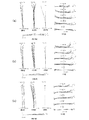
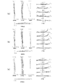
図4は、本第1実施例にかかるズームレンズにおける無限遠合焦時の諸収差図であり、(a)は広角端状態、(b)は中間焦点距離状態、(c)は望遠端状態をそれぞれ示す。図5は、本第1実施例にかかるズームレンズにおける至近距離合焦時の諸収差図であり、(a)は広角端状態、(b)は中間焦点距離状態、(c)は望遠端状態をそれぞれ示す。 4A and 4B are graphs showing various aberrations when the zoom lens according to the first example is in focus at infinity. FIG. 4A is a wide-angle end state, FIG. 4B is an intermediate focal length state, and FIG. 4C is a telephoto end state. Respectively. FIGS. 5A and 5B are graphs showing various aberrations when the zoom lens according to the first example is in focus at a close distance, where FIG. 5A is a wide-angle end state, FIG. 5B is an intermediate focal length state, and FIG. 5C is a telephoto end state. Respectively.
各収差図において、FNOはFナンバーを、Yは像高を、Aは半画角(単位:度)をそれぞれ示す。また、各収差図において、dはd線(λ=587.6nm)、gはg線(λ=435.8nm)、CはC線(λ=656.3nm)、FはF線(λ=486.1nm)の収差曲線をそれぞれ示す。さらに非点収差図において、実線はサジタル像面、破線はメリディオナル像面をそれぞれ示す。なお、以下に示す各実施例の諸収差図において、本実施例と同様の符号を用い説明を省略する。 In each aberration diagram, FNO represents an F number, Y represents an image height, and A represents a half angle of view (unit: degree). In each aberration diagram, d is d-line (λ = 587.6 nm), g is g-line (λ = 435.8 nm), C is C-line (λ = 656.3 nm), and F is F-line (λ = 486.1 nm). Each aberration curve is shown. Further, in the astigmatism diagram, the solid line indicates the sagittal image plane, and the broken line indicates the meridional image plane. In addition, in the various aberration diagrams of the following examples, the same reference numerals as those of the present example are used, and description thereof is omitted.
各収差図から、本第1実施例にかかるズームレンズは、広角端状態Wから望遠端状態Tまでの各焦点距離状態において、無限遠物体から至近距離物体にいたる全撮影領域において諸収差が良好に補正され、優れた光学性能を有することが分かる。 From each aberration diagram, the zoom lens according to the first example has good various aberrations in the entire imaging region from the object at infinity to the object at close distance in each focal length state from the wide-angle end state W to the telephoto end state T. It can be seen that the optical performance is excellent.
(第2実施例)
図6は、第2実施例にかかるズームレンズのレンズ構成を示す図である。
(Second embodiment)
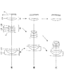
FIG. 6 is a diagram illustrating a lens configuration of a zoom lens according to the second example.
図6において、本第2実施例にかかるズームレンズは、光軸に沿って物体側から順に、負の屈折力を有する第1レンズ群G1と、開口絞りSと、正の屈折力を有する第2レンズ群G2と、正の屈折力を有する第3レンズ群G3とを有し、広角端状態Wから望遠端状態Tへの変倍に際し、第1レンズ群G1と第2レンズ群G2との間隔が減少し、第2レンズ群G2と第3レンズ群G3との間隔が増加するように、第1レンズ群G1と第2レンズ群G2が移動し、第3レンズ群G3が固定された構成である。 In FIG. 6, the zoom lens according to the second example includes a first lens group G1 having a negative refractive power, an aperture stop S, and a first lens having a positive refractive power in order from the object side along the optical axis. A second lens group G2 and a third lens group G3 having a positive refractive power, and at the time of zooming from the wide-angle end state W to the telephoto end state T, the first lens group G1 and the second lens group G2 A configuration in which the first lens group G1 and the second lens group G2 are moved and the third lens group G3 is fixed so that the distance is decreased and the distance between the second lens group G2 and the third lens group G3 is increased. It is.
第1レンズ群G1は、光軸に沿って物体側から順に、物体側に凸面を向けた負メニスカスレンズL11、物体側に凸面を向けた正メニスカスレンズL12とから構成され、負メニスカスレンズL11の像面I側のレンズ面、および正メニスカスレンズL12の物体側のレンズ面は非球面で構成されている。 The first lens group G1 includes, in order from the object side along the optical axis, a negative meniscus lens L11 having a convex surface facing the object side, and a positive meniscus lens L12 having a convex surface facing the object side. The lens surface on the image plane I side and the lens surface on the object side of the positive meniscus lens L12 are aspherical.
第2レンズ群G2は、光軸に沿って物体側から順に、第1正レンズL21、第2正レンズL22、負レンズL23、第3正レンズL24とから構成され、第2正レンズL22と負レンズL23とは接合されており、第1正レンズL21の物体側の面が非球面で構成されている。 The second lens group G2 includes, in order from the object side along the optical axis, a first positive lens L21, a second positive lens L22, a negative lens L23, and a third positive lens L24, and is negative with the second positive lens L22. The lens L23 is cemented, and the object-side surface of the first positive lens L21 is an aspherical surface.
第3レンズ群G3は1枚の正レンズL31のみからなり、正レンズL31の物体側の面が非球面で構成されている。 The third lens group G3 includes only one positive lens L31, and the object-side surface of the positive lens L31 is aspheric.
また、無限遠物体から有限距離物体へのフォーカシングは、第3レンズ群G3を光軸に沿って物体方向に移動させることによって行う。 Further, focusing from an infinitely distant object to a finite distance object is performed by moving the third lens group G3 along the optical axis in the object direction.
開口絞りSは、第2レンズ群G2の最も物体側の第1正レンズL21より物体側に配置されており、広角端状態Wから望遠端状態Tへの変倍に際し、第2レンズ群G2と一体的に移動する。 The aperture stop S is disposed closer to the object side than the first positive lens L21 closest to the object side in the second lens group G2, and when changing from the wide-angle end state W to the telephoto end state T, the aperture stop S and the second lens group G2 Move together.
また、フィルタ群FLは、赤外カットフィルタなどで構成されている。 The filter group FL is configured by an infrared cut filter or the like.
以下の表2に、本第2実施例にかかるズームレンズの諸元の値を掲載する。 Table 2 below shows values of specifications of the zoom lens according to the second example.
(表2)
[全体諸元]
f=4.81〜16.50
FNO=2.86〜5.58
2ω=77.4°〜24.8°
Ymax = 3.60
[レンズ諸元]
r d νd nd
1) 66.4286 1.1000 42.71 1.820800
*2) 5.2196 2.8500
*3) 12.5754 1.7500 21.15 1.906800
4) 32.0968 (d4)
5) ∞ 0.4000 開口絞りS
*6) 5.8236 1.6500 53.22 1.693500
7) -73.1640 0.3000
8) 8.7440 1.7000 52.29 1.755000
9) -10.7157 0.6000 32.35 1.850260
10) 3.9312 0.7500
11) 17.4699 1.3000 58.89 1.518230
12) -28.9368 (d12)
*13) 18.0000 1.7000 82.56 1.497820
14) -27.4095 (d14)
15) ∞ 0.5000 64.12 1.516800
16) ∞ (B.f.)
[非球面データ]
(第2面)
κ = 0.1614
C4 = 2.46350E-04
C6 = 2.73920E-06
C8 = -1.27140E-07
C10= 1.02310E-09
(第3面)
κ = 0.0592
C4 = 1.48600E-04
C6 = 0.00000E+00
C8 = 0.00000E+00
C10= 0.00000E+00
(第6面)
κ = 0.3901
C4 = -6.48660E-05
C6 = 0.00000E+00
C8 = 0.00000E+00
C10= 0.00000E+00
(第13面)
κ = 4.9245
C4 = -8.55640E-05
C6 = 0.00000E+00
C8 = 0.00000E+00
C10= 0.00000E+00
[可変間隔データ]
広角端状態 中間焦点距離状態 望遠端状態
f 4.81 8.80 16.50
D0 ∞ ∞ ∞
d4 16.98530 7.37241 1.96446
d12 3.98625 8.63480 17.60567
d14 3.30628 3.30628 3.30628
至近距離撮影時(撮影距離300mm)
広角端状態 中間焦点距離状態 望遠端状態
β -0.01791 -0.03196 -0.05808
D0 260.5821 265.5465 261.9835
d4 16.98530 7.37241 1.96446
d12 3.77076 7.95875 15.54431
d14 3.52177 3.98233 5.36764
[条件式対応数値]
(1)ft×Ymax / {fw×(fw+ft)} = 0.57951
(2)fw / TL = 0.12203
(3)|f1|/(fw×ft)1/2 = 1.34700
(4)(Rb+Ra)/(Rb−Ra) = 0.20721
(5)ν31 = 82.56
(6)fL11 / f1 = 0.57982
(7)n23 − n24 = 0.33203
(8)ν23 = 32.35
(9)Rc / Rd = 0.66601
(Table 2)
[Overall specifications]
f = 4.81-16.50
FNO = 2.86 ~ 5.58
2ω = 77.4 ° ~ 24.8 °
Ymax = 3.60
[Lens specifications]
rd νd nd
1) 66.4286 1.1000 42.71 1.820800
* 2) 5.2196 2.8500
* 3) 12.5754 1.7500 21.15 1.906800
4) 32.0968 (d4)
5) ∞ 0.4000 Aperture S
* 6) 5.8236 1.6500 53.22 1.693500
7) -73.1640 0.3000
8) 8.7440 1.7000 52.29 1.755000
9) -10.7157 0.6000 32.35 1.850 260
10) 3.9312 0.7500
11) 17.4699 1.3000 58.89 1.518230
12) -28.9368 (d12)
* 13) 18.0000 1.7000 82.56 1.497820
14) -27.4095 (d14)
15) ∞ 0.5000 64.12 1.516800
16) ∞ (Bf)
[Aspherical data]
(Second side)
κ = 0.1614
C4 = 2.46350E-04
C6 = 2.73920E-06
C8 = -1.27140E-07
C10 = 1.02310E-09
(Third side)
κ = 0.0592
C4 = 1.48600E-04
C6 = 0.00000E + 00
C8 = 0.00000E + 00
C10 = 0.00000E + 00
(Sixth surface)
κ = 0.3901
C4 = -6.48660E-05
C6 = 0.00000E + 00
C8 = 0.00000E + 00
C10 = 0.00000E + 00
(13th page)
κ = 4.9245
C4 = -8.55640E-05
C6 = 0.00000E + 00
C8 = 0.00000E + 00
C10 = 0.00000E + 00
[Variable interval data]
Wide-angle end state Intermediate focal length state Telephoto end state
f 4.81 8.80 16.50
D0 ∞ ∞ ∞
d4 16.98530 7.37241 1.96446
d12 3.98625 8.63480 17.60567
d14 3.30628 3.30628 3.30628
Close-up shooting (300mm shooting distance)
Wide-angle end state Intermediate focal length state Telephoto end state β -0.01791 -0.03196 -0.05808
D0 260.5821 265.5465 261.9835
d4 16.98530 7.37241 1.96446
d12 3.77076 7.95875 15.54431
d14 3.52177 3.98233 5.36764
[Values for conditional expressions]
(1) ft × Ymax / {fw × (fw + ft)} = 0.57951
(2) fw / TL = 0.12203
(3) | f1 | / (fw × ft) 1/2 = 1.34700
(4) (Rb + Ra) / (Rb-Ra) = 0.20721
(5) ν31 = 82.56
(6) fL11 / f1 = 0.57982
(7) n23−n24 = 0.320320
(8) ν23 = 32.35
(9) Rc / Rd = 0.66601
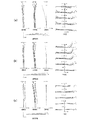
図7は、本第2実施例にかかるズームレンズにおける無限遠合焦時の諸収差図であり、(a)は広角端状態、(b)は中間焦点距離状態、(c)は望遠端状態をそれぞれ示す。図8は、本第2実施例にかかるズームレンズにおける至近距離合焦時の諸収差図であり、(a)は広角端状態、(b)は中間焦点距離状態、(c)は望遠端状態をそれぞれ示す。 FIGS. 7A and 7B are graphs showing various aberrations when the zoom lens according to the second example is in focus at infinity. FIG. 7A is a wide-angle end state, FIG. 7B is an intermediate focal length state, and FIG. 7C is a telephoto end state. Respectively. 8A and 8B are graphs showing various aberrations when the zoom lens according to the second example is in focus at a close distance. FIG. 8A is a wide-angle end state, FIG. 8B is an intermediate focal length state, and FIG. 8C is a telephoto end state. Respectively.
各収差図から、本第2実施例にかかるズームレンズは、広角端状態Wから望遠端状態Tまでの各焦点距離状態において、無限遠物体から至近距離物体にいたる全撮影領域において諸収差が良好に補正され、優れた光学性能を有することが分かる。 From each aberration diagram, the zoom lens according to the second example has good various aberrations in the entire imaging region from the object at infinity to the object at close distance in each focal length state from the wide-angle end state W to the telephoto end state T. It can be seen that the optical performance is excellent.
(第3実施例)
図9は、第3実施例にかかるズームレンズのレンズ構成を示す図である。
(Third embodiment)
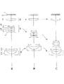
FIG. 9 is a diagram illustrating a lens configuration of a zoom lens according to the third example.
図9において、本第3実施例にかかるズームレンズは、光軸に沿って物体側から順に、負の屈折力を有する第1レンズ群G1と、開口絞りSと、正の屈折力を有する第2レンズ群G2と、正の屈折力を有する第3レンズ群G3とを有し、広角端状態Wから望遠端状態Tへの変倍に際し、第1レンズ群G1と第2レンズ群G2との間隔が減少し、第2レンズ群G2と第3レンズ群G3との間隔が増加するように、第1レンズ群G1と第2レンズ群G2が移動し、第3レンズ群G3が固定された構成である。 In FIG. 9, the zoom lens according to the third example has a first lens group G1 having a negative refractive power, an aperture stop S, and a first lens having a positive refractive power in order from the object side along the optical axis. A second lens group G2 and a third lens group G3 having a positive refractive power, and at the time of zooming from the wide-angle end state W to the telephoto end state T, the first lens group G1 and the second lens group G2 A configuration in which the first lens group G1 and the second lens group G2 are moved and the third lens group G3 is fixed so that the distance is decreased and the distance between the second lens group G2 and the third lens group G3 is increased. It is.
第1レンズ群G1は、光軸に沿って物体側から順に、物体側に凸面を向けた負メニスカスレンズL11、物体側に凸面を向けた正メニスカスレンズL12とから構成され、負メニスカスレンズL11の像面I側のレンズ面、および正メニスカスレンズL12の物体側のレンズ面は非球面で構成されている。 The first lens group G1 includes, in order from the object side along the optical axis, a negative meniscus lens L11 having a convex surface directed toward the object side, and a positive meniscus lens L12 having a convex surface directed toward the object side. The lens surface on the image plane I side and the lens surface on the object side of the positive meniscus lens L12 are aspherical.
第2レンズ群G2は、光軸に沿って物体側から順に、第1正レンズL21、第2正レンズL22、負レンズL23、第3正レンズL24とから構成され、第2正レンズL22と負レンズL23とは接合されており、第1正レンズL21の物体側の面が非球面で構成されている。 The second lens group G2 includes, in order from the object side along the optical axis, a first positive lens L21, a second positive lens L22, a negative lens L23, and a third positive lens L24, and is negative with the second positive lens L22. The lens L23 is cemented, and the object-side surface of the first positive lens L21 is an aspherical surface.
第3レンズ群G3は1枚の正レンズL31のみからなり、正レンズL31の物体側の面が非球面で構成されている。 The third lens group G3 includes only one positive lens L31, and the object-side surface of the positive lens L31 is aspheric.
また、無限遠物体から有限距離物体へのフォーカシングは、第3レンズ群G3を光軸に沿って物体方向に移動させることによって行う。 Further, focusing from an infinitely distant object to a finite distance object is performed by moving the third lens group G3 along the optical axis in the object direction.
開口絞りSは、第2レンズ群G2の最も物体側の第1正レンズL21より物体側に配置されており、広角端状態Wから望遠端状態Tへの変倍に際し、第2レンズ群G2と一体的に移動する。 The aperture stop S is disposed closer to the object side than the first positive lens L21 closest to the object side in the second lens group G2, and when changing from the wide-angle end state W to the telephoto end state T, the aperture stop S and the second lens group G2 Move together.
また、フィルタ群FLは、赤外カットフィルタなどで構成されている。 The filter group FL is configured by an infrared cut filter or the like.
以下の表3に、本第3実施例にかかるズームレンズの諸元の値を掲載する。 Table 3 below shows values of specifications of the zoom lens according to the third example.
(表3)
[全体諸元]
f=4.81〜16.50
FNO=2.86〜5.66
2ω=77.3°〜24.7°
Ymax = 3.60
[レンズ諸元]
r d νd nd
1) 65.0000 1.1000 42.71 1.820800
*2) 4.5216 2.5000
*3) 11.5186 1.7500 21.15 1.906800
4) 34.1760 (d4)
5) ∞ 0.4000 開口絞りS
*6) 5.7975 1.6500 53.22 1.693500
7) 119.2231 0.3000
8) 9.9279 1.7000 46.63 1.816000
9) -12.4084 0.6000 31.31 1.903660
10) 4.3266 0.7000
11) 11.5176 1.3000 58.89 1.518230
12) -17.4568 (d12)
*13) 11.5000 1.7000 91.20 1.456000
14)-1250.3048 (d14)
15) ∞ 0.5000 64.12 1.516800
16) ∞ (B.f.)
[非球面データ]
(第2面)
κ = 0.1500
C4 = 2.19490E-04
C6 = 7.09410E-06
C8 = -2.35900E-07
C10= 3.65970E-09
(第3面)
κ = 2.2992
C4 = -1.23090E-05
C6 = 0.00000E+00
C8 = 0.00000E+00
C10= 0.00000E+00
(第6面)
κ = 0.4355
C4 = -1.01430E-05
C6 = 0.00000E+00
C8 = 0.00000E+00
C10= 0.00000E+00
(第13面)
κ = 1.9690
C4 = -1.07400E-04
C6 = 0.00000E+00
C8 = 0.00000E+00
C10= 0.00000E+00
[可変間隔データ]
広角端状態 中間焦点距離状態 望遠端状態
f 4.81 8.80 16.50
D0 ∞ ∞ ∞
d4 15.03371 6.66824 1.96205
d12 4.85236 10.19407 20.50264
d14 3.24257 3.24257 3.24257
至近距離撮影時(撮影距離300mm)
広角端状態 中間焦点距離状態 望遠端状態
β -0.01790 -0.03219 -0.05914
D0 261.7861 264.8100 259.2075
d4 15.03371 6.66824 1.96205
d12 4.63999 9.51918 18.39947
d14 3.45494 3.91746 5.34575
[条件式対応数値]
(1)ft×Ymax / {fw×(fw+ft)} = 0.57951
(2)fw / TL = 0.11791
(3)|f1|/(fw×ft)1/2 = 1.17862
(4)(Rb+Ra)/(Rb−Ra) = 0.98177
(5)ν31 = 91.20
(6)fL11 / f1 = 0.56853
(7)n23 − n24 = 0.38543
(8)ν23 = 31.31
(9)Rc / Rd = 0.58396
(Table 3)
[Overall specifications]
f = 4.81-16.50
FNO = 2.86 ~ 5.66
2ω = 77.3 ° ~ 24.7 °
Ymax = 3.60
[Lens specifications]
rd νd nd
1) 65.0000 1.1000 42.71 1.820800
* 2) 4.5216 2.5000
* 3) 11.5186 1.7500 21.15 1.906800
4) 34.1760 (d4)
5) ∞ 0.4000 Aperture S
* 6) 5.7975 1.6500 53.22 1.693500
7) 119.2231 0.3000
8) 9.9279 1.7000 46.63 1.816000
9) -12.4084 0.6000 31.31 1.903660
10) 4.3266 0.7000
11) 11.5176 1.3000 58.89 1.518230
12) -17.4568 (d12)
* 13) 11.5000 1.7000 91.20 1.456000
14) -1250.3048 (d14)
15) ∞ 0.5000 64.12 1.516800
16) ∞ (Bf)
[Aspherical data]
(Second side)
κ = 0.1500
C4 = 2.19490E-04
C6 = 7.09410E-06
C8 = -2.35900E-07
C10 = 3.65970E-09
(Third side)
κ = 2.2992
C4 = -1.23090E-05
C6 = 0.00000E + 00
C8 = 0.00000E + 00
C10 = 0.00000E + 00
(Sixth surface)
κ = 0.4355
C4 = -1.01430E-05
C6 = 0.00000E + 00
C8 = 0.00000E + 00
C10 = 0.00000E + 00
(13th page)
κ = 1.9690
C4 = -1.07400E-04
C6 = 0.00000E + 00
C8 = 0.00000E + 00
C10 = 0.00000E + 00
[Variable interval data]
Wide-angle end state Intermediate focal length state Telephoto end state
f 4.81 8.80 16.50
D0 ∞ ∞ ∞
d4 15.03371 6.66824 1.96205
d12 4.85236 10.19407 20.50264
d14 3.24257 3.24257 3.24257
Close-up shooting (300mm shooting distance)
Wide-angle end state Intermediate focal length state Telephoto end state β -0.01790 -0.03219 -0.05914
D0 261.7861 264.8100 259.2075
d4 15.03371 6.66824 1.96205
d12 4.63999 9.51918 18.39947
d14 3.45494 3.91746 5.34575
[Values for conditional expressions]
(1) ft × Ymax / {fw × (fw + ft)} = 0.57951
(2) fw / TL = 0.11791
(3) | f1 | / (fw × ft) 1/2 = 1.17862
(4) (Rb + Ra) / (Rb−Ra) = 0.98177
(5) ν31 = 91.20
(6) fL11 / f1 = 0.56853
(7) n23-n24 = 0.38543
(8) ν23 = 31.31
(9) Rc / Rd = 0.58396
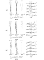
図10は、本第3実施例にかかるズームレンズにおける無限遠合焦時の諸収差図であり、(a)は広角端状態、(b)は中間焦点距離状態、(c)は望遠端状態をそれぞれ示す。図11は、本第3実施例にかかるズームレンズにおける至近距離合焦時の諸収差図であり、(a)は広角端状態、(b)は中間焦点距離状態、(c)は望遠端状態をそれぞれ示す。 10A and 10B are graphs showing various aberrations of the zoom lens according to the third example at the time of focusing on infinity, where FIG. 10A is a wide-angle end state, FIG. 10B is an intermediate focal length state, and FIG. 10C is a telephoto end state. Respectively. 11A and 11B are graphs showing various aberrations when the zoom lens according to the third example is in focus at a close distance, where FIG. 11A is a wide-angle end state, FIG. 11B is an intermediate focal length state, and FIG. 11C is a telephoto end state. Respectively.
各収差図から、本第3実施例にかかるズームレンズは、広角端状態Wから望遠端状態Tまでの各焦点距離状態において、無限遠物体から至近距離物体にいたる全撮影領域において諸収差が良好に補正され、優れた光学性能を有することが分かる。 From each aberration diagram, the zoom lens according to the third example has good various aberrations in the entire imaging region from the object at infinity to the object at close distance in each focal length state from the wide-angle end state W to the telephoto end state T. It can be seen that the optical performance is excellent.
(第4実施例)
図12は、第4実施例にかかるズームレンズのレンズ構成を示す図である。
(Fourth embodiment)
FIG. 12 is a diagram illustrating a lens configuration of a zoom lens according to the fourth example.
図12において、本第4実施例にかかるズームレンズは、光軸に沿って物体側から順に、負の屈折力を有する第1レンズ群G1と、開口絞りSと、正の屈折力を有する第2レンズ群G2と、正の屈折力を有する第3レンズ群G3とを有し、広角端状態Wから望遠端状態Tへの変倍に際し、第1レンズ群G1と第2レンズ群G2との間隔が減少し、第2レンズ群G2と第3レンズ群G3との間隔が増加するように、第1レンズ群G1と第2レンズ群G2が移動し、第3レンズ群G3が固定された構成である。 In FIG. 12, the zoom lens according to the fourth example includes a first lens group G1 having a negative refractive power, an aperture stop S, and a first lens having a positive refractive power in order from the object side along the optical axis. A second lens group G2 and a third lens group G3 having a positive refractive power, and at the time of zooming from the wide-angle end state W to the telephoto end state T, the first lens group G1 and the second lens group G2 A configuration in which the first lens group G1 and the second lens group G2 are moved and the third lens group G3 is fixed so that the distance is decreased and the distance between the second lens group G2 and the third lens group G3 is increased. It is.
第1レンズ群G1は、光軸に沿って物体側から順に、物体側に凸面を向けた負メニスカスレンズL11、物体側に凸面を向けた正メニスカスレンズL12とから構成され、負メニスカスレンズL11の像面I側のレンズ面、および正メニスカスレンズL12の物体側のレンズ面は非球面で構成されている。 The first lens group G1 includes, in order from the object side along the optical axis, a negative meniscus lens L11 having a convex surface directed toward the object side, and a positive meniscus lens L12 having a convex surface directed toward the object side. The lens surface on the image plane I side and the lens surface on the object side of the positive meniscus lens L12 are aspherical.
第2レンズ群G2は、光軸に沿って物体側から順に、第1正レンズL21、第2正レンズL22、負レンズL23、第3正レンズL24とから構成され、第2正レンズL22と負レンズL23とは接合されており、第1正レンズL21の物体側の面が非球面で構成されている。 The second lens group G2 includes, in order from the object side along the optical axis, a first positive lens L21, a second positive lens L22, a negative lens L23, and a third positive lens L24, and is negative with the second positive lens L22. The lens L23 is cemented, and the object-side surface of the first positive lens L21 is an aspherical surface.
第3レンズ群G3は1枚の正レンズL31のみからなり、正レンズL31の物体側の面が非球面で構成されている。 The third lens group G3 includes only one positive lens L31, and the object-side surface of the positive lens L31 is aspheric.
また、無限遠物体から有限距離物体へのフォーカシングは、第3レンズ群G3を光軸に沿って物体方向に移動させることによって行う。 Further, focusing from an infinitely distant object to a finite distance object is performed by moving the third lens group G3 along the optical axis in the object direction.
開口絞りSは、第2レンズ群G2の最も物体側の第1正レンズL21より物体側に配置されており、広角端状態Wから望遠端状態Tへの変倍に際し、第2レンズ群G2と一体的に移動する。 The aperture stop S is disposed closer to the object side than the first positive lens L21 closest to the object side in the second lens group G2, and when changing from the wide-angle end state W to the telephoto end state T, the aperture stop S and the second lens group G2 Move together.
また、フィルタ群FLは、赤外カットフィルタなどで構成されている。 The filter group FL is configured by an infrared cut filter or the like.
以下の表4に、本第4実施例にかかるズームレンズの諸元の値を掲載する。 Table 4 below provides values of specifications of the zoom lens according to the fourth example.
(表4)
[全体諸元]
f=4.81〜16.50
FNO=2.92〜5.67
2ω=77.4°〜24.6°
Ymax = 3.60
[レンズ諸元]
r d νd nd
1) 58.0000 1.1000 42.71 1.820800
*2) 4.6965 2.4500
*3) 10.8719 1.7500 21.15 1.906800
4) 28.4117 (d4)
5) ∞ 0.4000 開口絞りS
*6) 5.8878 1.6000 53.22 1.693500
7) 177.6627 0.3000
8) 9.8962 1.7500 46.63 1.816000
9) -11.1646 0.6000 31.31 1.903660
10) 4.3404 0.7000
11) 11.7963 1.3000 56.71 1.607380
12) -28.0907 (d12)
*13) 9.7000 1.7000 82.56 1.497820
14) 49.4505 (d14)
15) ∞ 0.5000 64.12 1.516800
16) ∞ (B.f.)
[非球面データ]
(第2面)
κ = 0.1500
C4 = 1.91050E-04
C6 = 5.54180E-06
C8 = -1.60350E-07
C10= 2.32790E-09
(第3面)
κ = 1.8300
C4 = -3.14850E-05
C6 = 0.00000E+00
C8 = 0.00000E+00
C10= 0.00000E+00
(第6面)
κ = 0.4230
C4 = 1.47380E-05
C6 = 0.00000E+00
C8 = 0.00000E+00
C10= 0.00000E+00
(第13面)
κ = 1.5525
C4 = -9.66340E-05
C6 = 0.00000E+00
C8 = 0.00000E+00
C10= 0.00000E+00
[可変間隔データ]
広角端状態 中間焦点距離状態 望遠端状態
f 4.81 8.80 16.50
D0 ∞ ∞ ∞
d4 15.99055 7.01290 1.96231
d12 5.19942 10.17688 19.78252
d14 3.00784 3.00784 3.00784
至近距離撮影時(撮影距離300mm)
広角端状態 中間焦点距離状態 望遠端状態
β -0.01790 -0.03208 -0.05865
D0 261.1271 265.1274 260.5723
d4 15.99055 7.01290 1.96231
d12 4.98328 9.49444 17.67893
d14 3.22398 3.69028 5.11143
[条件式対応数値]
(1)ft×Ymax / {fw×(fw+ft)} = 0.57951
(2)fw / TL = 0.12200
(3)|f1|/(fw×ft)1/2 = 1.25720
(4)(Rb+Ra)/(Rb−Ra) = 1.48804
(5)ν31 = 82.56
(6)fL11 / f1 = 0.56111
(7)n23 − n24 = 0.29628
(8)ν23 = 31.31
(9)Rc / Rd = 0.59496
(Table 4)
[Overall specifications]
f = 4.81-16.50
FNO = 2.92-5.67
2ω = 77.4 ° ~ 24.6 °
Ymax = 3.60
[Lens specifications]
rd νd nd
1) 58.0000 1.1000 42.71 1.820800
* 2) 4.6965 2.4500
* 3) 10.8719 1.7500 21.15 1.906800
4) 28.4117 (d4)
5) ∞ 0.4000 Aperture S
* 6) 5.8878 1.6000 53.22 1.693500
7) 177.6627 0.3000
8) 9.8962 1.7500 46.63 1.816000
9) -11.1646 0.6000 31.31 1.903660
10) 4.3404 0.7000
11) 11.7963 1.3000 56.71 1.607380
12) -28.0907 (d12)
* 13) 9.7000 1.7000 82.56 1.497820
14) 49.4505 (d14)
15) ∞ 0.5000 64.12 1.516800
16) ∞ (Bf)
[Aspherical data]
(Second side)
κ = 0.1500
C4 = 1.91050E-04
C6 = 5.54180E-06
C8 = -1.60350E-07
C10 = 2.32790E-09
(Third side)
κ = 1.8300
C4 = -3.14850E-05
C6 = 0.00000E + 00
C8 = 0.00000E + 00
C10 = 0.00000E + 00
(Sixth surface)
κ = 0.4230
C4 = 1.47380E-05
C6 = 0.00000E + 00
C8 = 0.00000E + 00
C10 = 0.00000E + 00
(13th page)
κ = 1.5525
C4 = -9.66340E-05
C6 = 0.00000E + 00
C8 = 0.00000E + 00
C10 = 0.00000E + 00
[Variable interval data]
Wide-angle end state Intermediate focal length state Telephoto end state
f 4.81 8.80 16.50
D0 ∞ ∞ ∞
d4 15.99055 7.01290 1.96231
d12 5.19942 10.17688 19.78252
d14 3.00784 3.00784 3.00784
Close-up shooting (300mm shooting distance)
Wide-angle end state Intermediate focal length state Telephoto end state β -0.01790 -0.03208 -0.05865
D0 261.1271 265.1274 260.5723
d4 15.99055 7.01290 1.96231
d12 4.98328 9.49444 17.67893
d14 3.22398 3.69028 5.11143
[Values for conditional expressions]
(1) ft × Ymax / {fw × (fw + ft)} = 0.57951
(2) fw / TL = 0.12200
(3) | f1 | / (fw × ft) 1/2 = 1.25720
(4) (Rb + Ra) / (Rb−Ra) = 1.48804
(5) ν31 = 82.56
(6) fL11 / f1 = 0.56111
(7) n23−n24 = 0.29628
(8) ν23 = 31.31
(9) Rc / Rd = 0.59496
図13は、本第4実施例にかかるズームレンズにおける無限遠合焦時の諸収差図であり、(a)は広角端状態、(b)は中間焦点距離状態、(c)は望遠端状態をそれぞれ示す。図14は、本第4実施例にかかるズームレンズにおける至近距離合焦時の諸収差図であり、(a)は広角端状態、(b)は中間焦点距離状態、(c)は望遠端状態をそれぞれ示す。 FIGS. 13A and 13B are graphs showing various aberrations of the zoom lens according to the fourth example at the time of focusing at infinity, where FIG. 13A is a wide-angle end state, FIG. 13B is an intermediate focal length state, and FIG. 13C is a telephoto end state. Respectively. FIGS. 14A and 14B are graphs showing various aberrations when the zoom lens according to the fourth example is in focus at a close distance, where FIG. 14A is a wide-angle end state, FIG. 14B is an intermediate focal length state, and FIG. 14C is a telephoto end state. Respectively.
各収差図から、本第4実施例にかかるズームレンズは、広角端状態Wから望遠端状態Tまでの各焦点距離状態において、無限遠物体から至近距離物体にいたる全撮影領域において諸収差が良好に補正され、優れた光学性能を有することが分かる。 From the respective aberration diagrams, the zoom lens according to the fourth example has good various aberrations in the entire imaging region from the object at infinity to the object at close distance in each focal length state from the wide-angle end state W to the telephoto end state T. It can be seen that the optical performance is excellent.
(第5実施例)
図15、第5実施例にかかるズームレンズのレンズ構成を示す図である。
(5th Example)
FIG. 15 is a diagram illustrating a lens configuration of a zoom lens according to a fifth example.
図15おいて、本第5実施例にかかるズームレンズは、光軸に沿って物体側から順に、負の屈折力を有する第1レンズ群G1と、開口絞りSと、正の屈折力を有する第2レンズ群G2と、正の屈折力を有する第3レンズ群G3とを有し、広角端状態Wから望遠端状態Tへの変倍に際し、第1レンズ群G1と第2レンズ群G2との間隔が減少し、第2レンズ群G2と第3レンズ群G3との間隔が増加するように、第1レンズ群G1と第2レンズ群G2が移動し、第3レンズ群G3が固定された構成である。 In FIG. 15, the zoom lens according to the fifth example has a first lens group G1 having a negative refractive power, an aperture stop S, and a positive refractive power in order from the object side along the optical axis. A second lens group G2 and a third lens group G3 having a positive refractive power. When zooming from the wide-angle end state W to the telephoto end state T, the first lens group G1 and the second lens group G2 The first lens group G1 and the second lens group G2 are moved so that the distance between the second lens group G2 and the third lens group G3 is increased, and the third lens group G3 is fixed. It is a configuration.
第1レンズ群G1は、光軸に沿って物体側から順に、物体側に凸面を向けた負メニスカスレンズL11、物体側に凸面を向けた正メニスカスレンズL12とから構成され、負メニスカスレンズL11の像面I側のレンズ面、および正メニスカスレンズL12の物体側のレンズ面は非球面で構成されている。 The first lens group G1 includes, in order from the object side along the optical axis, a negative meniscus lens L11 having a convex surface facing the object side, and a positive meniscus lens L12 having a convex surface facing the object side. The lens surface on the image plane I side and the lens surface on the object side of the positive meniscus lens L12 are aspherical.
第2レンズ群G2は、光軸に沿って物体側から順に、第1正レンズL21、第2正レンズL22、負レンズL23、第3正レンズL24とから構成され、第2正レンズL22と負レンズL23とは接合されており、第1正レンズL21の物体側の面が非球面で構成されている。 The second lens group G2 includes, in order from the object side along the optical axis, a first positive lens L21, a second positive lens L22, a negative lens L23, and a third positive lens L24, and is negative with the second positive lens L22. The lens L23 is cemented, and the object-side surface of the first positive lens L21 is an aspherical surface.
第3レンズ群G3は1枚の正レンズL31のみからなり、正レンズL31の物体側の面が非球面で構成されている。 The third lens group G3 includes only one positive lens L31, and the object-side surface of the positive lens L31 is aspheric.
また、無限遠物体から有限距離物体へのフォーカシングは、第3レンズ群G3を光軸に沿って物体方向に移動させることによって行う。 Further, focusing from an infinitely distant object to a finite distance object is performed by moving the third lens group G3 along the optical axis in the object direction.
開口絞りSは、第2レンズ群G2の最も物体側の第1正レンズL21より物体側に配置されており、広角端状態Wから望遠端状態Tへの変倍に際し、第2レンズ群G2と一体的に移動する。 The aperture stop S is disposed closer to the object side than the first positive lens L21 closest to the object side in the second lens group G2, and when changing from the wide-angle end state W to the telephoto end state T, the aperture stop S and the second lens group G2 Move together.
また、フィルタ群FLは、赤外カットフィルタなどで構成されている。 The filter group FL is configured by an infrared cut filter or the like.
以下の表5に、本第5実施例にかかるズームレンズの諸元の値を掲載する。 Table 5 below provides values of specifications of the zoom lens according to the fifth example.
(表5)
[全体諸元]
f=4.81〜16.50
FNO=2.84〜5.60
2ω=77.4°〜24.6°
Ymax = 3.60
[レンズ諸元]
r d νd nd
1) 62.0000 1.1000 42.71 1.820800
*2) 4.9347 2.8000
*3) 12.9259 1.7500 21.15 1.906800
4) 35.9751 (d4)
5) ∞ 0.4000 開口絞りS
*6) 5.9064 1.6000 53.22 1.693500
7) -185.6734 0.3000
8) 9.0667 1.7500 46.63 1.816000
9) -10.7695 0.6000 31.31 1.903660
10) 4.1588 0.7000
11) 17.0912 1.3000 52.32 1.517420
12) -18.8274 (d12)
13) 25.0000 1.7000 91.20 1.456000
*14) -18.9097 (d14)
15) ∞ 0.5000 64.12 1.516800
16) ∞ (B.f.)
[非球面データ]
(第2面)
κ = 0.1500
C4 = 3.52870E-04
C6 = 4.63320E-06
C8 = -1.50190E-07
C10= 1.10830E-09
(第3面)
κ = 1.8300
C4 = 9.73150E-05
C6 = 0.00000E+00
C8 = 0.00000E+00
C10= 0.00000E+00
(第6面)
κ = 0.4230
C4 = -6.31670E-05
C6 = 0.00000E+00
C8 = 0.00000E+00
C10= 0.00000E+00
(第14面)
κ = 3.7977
C4 = 1.33350E-04
C6 = 0.00000E+00
C8 = 0.00000E+00
C10= 0.00000E+00
[可変間隔データ]
広角端状態 中間焦点距離状態 望遠端状態
f 4.81 8.80 16.50
D0 ∞ ∞ ∞
d4 15.99579 7.01814 1.96755
d12 3.95555 8.93301 18.53865
D14 3.89101 3.89101 3.89101
至近距離撮影時(撮影距離300mm)
広角端状態 中間焦点距離状態 望遠端状態
β -0.01791 -0.03209 -0.05866
D0 261.1326 265.1329 260.5778
d4 15.99579 7.01814 1.96755
d12 3.73937 8.25045 16.43472
d14 4.10719 4.57357 5.99493
[条件式対応数値]
(1)ft×Ymax / {fw×(fw+ft)} = 0.57951
(2)fw / TL = 0.12201
(3)|f1|/(fw×ft)1/2 = 1.25720
(4)(Rb+Ra)/(Rb−Ra) = -0.13870
(5)ν31 = 91.20
(6)fL11 / f1 = 0.58833
(7)n23 − n24 = 0.38624
(8)ν23 = 31.31
(9)Rc / Rd = 0.65144
(Table 5)
[Overall specifications]
f = 4.81-16.50
FNO = 2.84-5.60
2ω = 77.4 ° ~ 24.6 °
Ymax = 3.60
[Lens specifications]
rd νd nd
1) 62.0000 1.1000 42.71 1.820800
* 2) 4.9347 2.8000
* 3) 12.9259 1.7500 21.15 1.906800
4) 35.9751 (d4)
5) ∞ 0.4000 Aperture S
* 6) 5.9064 1.6000 53.22 1.693500
7) -185.6734 0.3000
8) 9.0667 1.7500 46.63 1.816000
9) -10.7695 0.6000 31.31 1.903660
10) 4.1588 0.7000
11) 17.0912 1.3000 52.32 1.517420
12) -18.8274 (d12)
13) 25.0000 1.7000 91.20 1.456000
* 14) -18.9097 (d14)
15) ∞ 0.5000 64.12 1.516800
16) ∞ (Bf)
[Aspherical data]
(Second side)
κ = 0.1500
C4 = 3.52870E-04
C6 = 4.63320E-06
C8 = -1.50190E-07
C10 = 1.10830E-09
(Third side)
κ = 1.8300
C4 = 9.73150E-05
C6 = 0.00000E + 00
C8 = 0.00000E + 00
C10 = 0.00000E + 00
(Sixth surface)
κ = 0.4230
C4 = -6.31670E-05
C6 = 0.00000E + 00
C8 = 0.00000E + 00
C10 = 0.00000E + 00
(14th page)
κ = 3.7977
C4 = 1.33350E-04
C6 = 0.00000E + 00
C8 = 0.00000E + 00
C10 = 0.00000E + 00
[Variable interval data]
Wide-angle end state Intermediate focal length state Telephoto end state
f 4.81 8.80 16.50
D0 ∞ ∞ ∞
d4 15.99579 7.01814 1.96755
d12 3.95555 8.93301 18.53865
D14 3.89101 3.89101 3.89101
Close-up shooting (300mm shooting distance)
Wide-angle end state Intermediate focal length state Telephoto end state β -0.01791 -0.03209 -0.05866
D0 261.1326 265.1329 260.5778
d4 15.99579 7.01814 1.96755
d12 3.73937 8.25045 16.43472
d14 4.10719 4.57357 5.99493
[Values for conditional expressions]
(1) ft × Ymax / {fw × (fw + ft)} = 0.57951
(2) fw / TL = 0.12201
(3) | f1 | / (fw × ft) 1/2 = 1.25720
(4) (Rb + Ra) / (Rb-Ra) = -0.13870
(5) ν31 = 91.20
(6) fL11 / f1 = 0.58833
(7) n23-n24 = 0.38624
(8) ν23 = 31.31
(9) Rc / Rd = 0.65144
図16は、本第5実施例にかかるズームレンズにおける無限遠合焦時の諸収差図であり、(a)は広角端状態、(b)は中間焦点距離状態、(c)は望遠端状態をそれぞれ示す。図17は、本第5実施例にかかるズームレンズにおける至近距離合焦時の諸収差図であり、(a)は広角端状態、(b)は中間焦点距離状態、(c)は望遠端状態をそれぞれ示す。 FIGS. 16A and 16B are graphs showing various aberrations of the zoom lens according to the fifth example at the time of focusing on infinity, where FIG. 16A is a wide-angle end state, FIG. 16B is an intermediate focal length state, and FIG. 16C is a telephoto end state. Respectively. FIGS. 17A and 17B are graphs showing various aberrations when the zoom lens according to the fifth example is in focus at a close distance, where FIG. 17A is a wide-angle end state, FIG. 17B is an intermediate focal length state, and FIG. 17C is a telephoto end state. Respectively.
各収差図から、本第5実施例にかかるズームレンズは、広角端状態Wから望遠端状態Tまでの各焦点距離状態において、無限遠物体から至近距離物体にいたる全撮影領域において諸収差が良好に補正され、優れた光学性能を有することが分かる。 From each aberration diagram, the zoom lens according to the fifth example has good various aberrations in the entire imaging region from the object at infinity to the object at close distance in each focal length state from the wide-angle end state W to the telephoto end state T. It can be seen that the optical performance is excellent.
(第6実施例)
図18は、第6実施例にかかるズームレンズのレンズ構成を示す図である。
(Sixth embodiment)
FIG. 18 is a diagram illustrating a lens configuration of a zoom lens according to the sixth example.
図18において、本第6実施例にかかるズームレンズは、光軸に沿って物体側から順に、負の屈折力を有する第1レンズ群G1と、開口絞りSと、正の屈折力を有する第2レンズ群G2と、正の屈折力を有する第3レンズ群G3とを有し、広角端状態Wから望遠端状態Tへの変倍に際し、第1レンズ群G1と第2レンズ群G2との間隔が減少し、第2レンズ群G2と第3レンズ群G3との間隔が増加するように、第1レンズ群G1と第2レンズ群G2が移動し、第3レンズ群G3が固定された構成である。 In FIG. 18, in the zoom lens according to the sixth example, in order from the object side along the optical axis, a first lens group G1 having a negative refractive power, an aperture stop S, and a first lens having a positive refractive power. A second lens group G2 and a third lens group G3 having a positive refractive power, and at the time of zooming from the wide-angle end state W to the telephoto end state T, the first lens group G1 and the second lens group G2 A configuration in which the first lens group G1 and the second lens group G2 are moved and the third lens group G3 is fixed so that the distance is decreased and the distance between the second lens group G2 and the third lens group G3 is increased. It is.
第1レンズ群G1は、光軸に沿って物体側から順に、物体側に凸面を向けた負メニスカスレンズL11、物体側に凸面を向けた正メニスカスレンズL12とから構成され、負メニスカスレンズL11の像面I側のレンズ面、および正メニスカスレンズL12の物体側のレンズ面は非球面で構成されている。 The first lens group G1 includes, in order from the object side along the optical axis, a negative meniscus lens L11 having a convex surface facing the object side, and a positive meniscus lens L12 having a convex surface facing the object side. The lens surface on the image plane I side and the lens surface on the object side of the positive meniscus lens L12 are aspherical.
第2レンズ群G2は、光軸に沿って物体側から順に、第1正レンズL21、第2正レンズL22、負レンズL23、第3正レンズL24とから構成され、第2正レンズL22と負レンズL23とは接合されており、第1正レンズL21の物体側の面が非球面で構成されている。 The second lens group G2 includes, in order from the object side along the optical axis, a first positive lens L21, a second positive lens L22, a negative lens L23, and a third positive lens L24, and is negative with the second positive lens L22. The lens L23 is cemented, and the object-side surface of the first positive lens L21 is an aspherical surface.
第3レンズ群G3は1枚の正レンズL31のみからなり、正レンズL31の物体側の面が非球面で構成されている。 The third lens group G3 includes only one positive lens L31, and the object-side surface of the positive lens L31 is aspheric.
また、無限遠物体から有限距離物体へのフォーカシングは、第3レンズ群G3を光軸に沿って物体方向に移動させることによって行う。 Further, focusing from an infinitely distant object to a finite distance object is performed by moving the third lens group G3 along the optical axis in the object direction.
開口絞りSは、第2レンズ群G2の最も物体側の第1正レンズL21より物体側に配置されており、広角端状態Wから望遠端状態Tへの変倍に際し、第2レンズ群G2と一体的に移動する。 The aperture stop S is disposed closer to the object side than the first positive lens L21 closest to the object side in the second lens group G2, and when changing from the wide-angle end state W to the telephoto end state T, the aperture stop S and the second lens group G2 Move together.
また、フィルタ群FLは、赤外カットフィルタなどで構成されている。 The filter group FL is configured by an infrared cut filter or the like.
以下の表6に、本第6実施例にかかるズームレンズの諸元の値を掲載する。 Table 6 below provides values of specifications of the zoom lens according to the sixth example.
(表6)
[全体諸元]
f=4.81〜17.00
FNO=2.79〜5.65
2ω=77.3°〜23.9°
Ymax = 3.60
[レンズ諸元]
r d νd nd
1) 67.0000 1.1000 42.71 1.820800
*2) 4.8227 2.6000
*3) 11.8932 1.7500 21.15 1.906800
4) 33.3246 (d4)
5) ∞ 0.4000 開口絞りS
*6) 5.5196 1.8000 53.22 1.693500
7) -91.2466 0.3000
8) 8.8018 1.6000 40.77 1.883000
9) -13.7085 0.6000 28.27 2.003300
10) 3.9205 0.7000
11) 10.9202 1.3000 39.23 1.595510
12) -54.5371 (d12)
*13) 13.0570 1.7000 82.56 1.497820
14) -95.7012 (d14)
15) ∞ 0.5000 64.12 1.516800
16) ∞ (B.f.)
[非球面データ]
(第2面)
κ = 0.1500
C4 = 2.46190E-04
C6 = 5.67570E-06
C8 = -2.20830E-07
C10= 2.86050E-09
(第3面)
κ = 1.8300
C4 = 3.01910E-05
C6 = 0.00000E+00
C8 = 0.00000E+00
C10= 0.00000E+00
(第6面)
κ = 0.3052
C4 = 2.21230E-05
C6 = 0.00000E+00
C8 = 0.00000E+00
C10= 0.00000E+00
(第13面)
κ = 2.8390
C4 = -1.08200E-04
C6 = 0.00000E+00
C8 = 0.00000E+00
C10= 0.00000E+00
[可変間隔データ]
広角端状態 中間焦点距離状態 望遠端状態
f 4.81 8.80 17.00
D0 ∞ ∞ ∞
d4 15.89339 7.07705 1.95050
d12 4.44648 9.14984 18.81590
d14 2.89606 2.89606 2.89606
至近距離撮影時(撮影距離300mm)
広角端状態 中間焦点距離状態 望遠端状態
β -0.01785 -0.03193 -0.05975
D0 261.8948 266.0079 261.4683
d4 15.89339 7.07705 1.95050
d12 4.21772 8.43311 16.53634
d14 3.12482 3.61279 5.17561
[条件式対応数値]
(1)ft×Ymax / {fw×(fw+ft)} = 0.58338
(2)fw / TL = 0.12483
(3)|f1|/(fw×ft)1/2 = 1.23857
(4)(Rb+Ra)/(Rb−Ra) = 0.75989
(5)ν31 = 82.56
(6)fL11 / f1 = 0.56984
(7)n23 − n24 = 0.40779
(8)ν23 = 28.27
(9)Rc / Rd = 0.62710
(Table 6)
[Overall specifications]
f = 4.81-17.00
FNO = 2.79-5.65
2ω = 77.3 ° ~ 23.9 °
Ymax = 3.60
[Lens specifications]
rd νd nd
1) 67.0000 1.1000 42.71 1.820800
* 2) 4.8227 2.6000
* 3) 11.8932 1.7500 21.15 1.906800
4) 33.3246 (d4)
5) ∞ 0.4000 Aperture S
* 6) 5.5196 1.8000 53.22 1.693500
7) -91.2466 0.3000
8) 8.8018 1.6000 40.77 1.883000
9) -13.7085 0.6000 28.27 2.003300
10) 3.9205 0.7000
11) 10.9202 1.3000 39.23 1.595510
12) -54.5371 (d12)
* 13) 13.0570 1.7000 82.56 1.497820
14) -95.7012 (d14)
15) ∞ 0.5000 64.12 1.516800
16) ∞ (Bf)
[Aspherical data]
(Second side)
κ = 0.1500
C4 = 2.46190E-04
C6 = 5.67570E-06
C8 = -2.20830E-07
C10 = 2.86050E-09
(Third side)
κ = 1.8300
C4 = 3.01910E-05
C6 = 0.00000E + 00
C8 = 0.00000E + 00
C10 = 0.00000E + 00
(Sixth surface)
κ = 0.3052
C4 = 2.21230E-05
C6 = 0.00000E + 00
C8 = 0.00000E + 00
C10 = 0.00000E + 00
(13th page)
κ = 2.8390
C4 = -1.08200E-04
C6 = 0.00000E + 00
C8 = 0.00000E + 00
C10 = 0.00000E + 00
[Variable interval data]
Wide-angle end state Intermediate focal length state Telephoto end state
f 4.81 8.80 17.00
D0 ∞ ∞ ∞
d4 15.89339 7.07705 1.95050
d12 4.44648 9.14984 18.81590
d14 2.89606 2.89606 2.89606
Close-up shooting (300mm shooting distance)
Wide-angle end state Intermediate focal length state Telephoto end state β -0.01785 -0.03193 -0.05975
D0 261.8948 266.0079 261.4683
d4 15.89339 7.07705 1.95050
d12 4.21772 8.43311 16.53634
d14 3.12482 3.61279 5.17561
[Values for conditional expressions]
(1) ft × Ymax / {fw × (fw + ft)} = 0.58338
(2) fw / TL = 0.12483
(3) | f1 | / (fw × ft) 1/2 = 1.23857
(4) (Rb + Ra) / (Rb-Ra) = 0.75989
(5) ν31 = 82.56
(6) fL11 / f1 = 0.56984
(7) n23-n24 = 0.40779
(8) ν23 = 28.27
(9) Rc / Rd = 0.62710
図19は、本第6実施例にかかるズームレンズにおける無限遠合焦時の諸収差図であり、(a)は広角端状態、(b)は中間焦点距離状態、(c)は望遠端状態をそれぞれ示す。図20は、本第6実施例にかかるズームレンズにおける至近距離合焦時の諸収差図であり、(a)は広角端状態、(b)は中間焦点距離状態、(c)は望遠端状態をそれぞれ示す。 19A and 19B are graphs showing various aberrations of the zoom lens according to the sixth example at the time of focusing on infinity. FIG. 19A is a wide-angle end state, FIG. 19B is an intermediate focal length state, and FIG. 19C is a telephoto end state. Respectively. FIGS. 20A and 20B are graphs showing various aberrations when the zoom lens according to the sixth example is in focus at a close distance, where FIG. 20A is a wide-angle end state, FIG. 20B is an intermediate focal length state, and FIG. 20C is a telephoto end state. Respectively.
各収差図から、本第6実施例にかかるズームレンズは、広角端状態Wから望遠端状態Tまでの各焦点距離状態において、無限遠物体から至近距離物体にいたる全撮影領域において諸収差が良好に補正され、優れた光学性能を有することが分かる。 From each aberration diagram, the zoom lens according to the sixth example has good various aberrations in the entire imaging region from the object at infinity to the object at close distance in each focal length state from the wide-angle end state W to the telephoto end state T. It can be seen that the optical performance is excellent.
(第7実施例)
図21は、第7実施例にかかるズームレンズのレンズ構成を示す図である。
(Seventh embodiment)
FIG. 21 is a diagram illustrating a lens configuration of a zoom lens according to the seventh example.
図21において、本第7実施例にかかるズームレンズは、光軸に沿って物体側から順に、負の屈折力を有する第1レンズ群G1と、開口絞りSと、正の屈折力を有する第2レンズ群G2と、正の屈折力を有する第3レンズ群G3とを有し、広角端状態Wから望遠端状態Tへの変倍に際し、第1レンズ群G1と第2レンズ群G2との間隔が減少し、第2レンズ群G2と第3レンズ群G3との間隔が増加するように、第1レンズ群G1と第2レンズ群G2が移動し、第3レンズ群G3が固定された構成である。 In FIG. 21, the zoom lens according to the seventh example includes a first lens group G1 having a negative refractive power, an aperture stop S, and a first lens having a positive refractive power in order from the object side along the optical axis. A second lens group G2 and a third lens group G3 having a positive refractive power, and at the time of zooming from the wide-angle end state W to the telephoto end state T, the first lens group G1 and the second lens group G2 A configuration in which the first lens group G1 and the second lens group G2 are moved and the third lens group G3 is fixed so that the distance is decreased and the distance between the second lens group G2 and the third lens group G3 is increased. It is.
第1レンズ群G1は、光軸に沿って物体側から順に、物体側に凸面を向けた負メニスカスレンズL11、物体側に凸面を向けた正メニスカスレンズL12とから構成され、負メニスカスレンズL11の像面I側のレンズ面、および正メニスカスレンズL12の物体側のレンズ面は非球面で構成されている。 The first lens group G1 includes, in order from the object side along the optical axis, a negative meniscus lens L11 having a convex surface facing the object side, and a positive meniscus lens L12 having a convex surface facing the object side. The lens surface on the image plane I side and the lens surface on the object side of the positive meniscus lens L12 are aspherical.
第2レンズ群G2は、光軸に沿って物体側から順に、第1正レンズL21、第2正レンズL22、負レンズL23、第3正レンズL24とから構成され、第2正レンズL22と負レンズL23とは接合されており、第1正レンズL21の物体側の面が非球面で構成されている。 The second lens group G2 includes, in order from the object side along the optical axis, a first positive lens L21, a second positive lens L22, a negative lens L23, and a third positive lens L24, and is negative with the second positive lens L22. The lens L23 is cemented, and the object-side surface of the first positive lens L21 is an aspherical surface.
第3レンズ群G3は1枚の正レンズL31のみからなり、正レンズL31の物体側の面が非球面で構成されている。 The third lens group G3 includes only one positive lens L31, and the object-side surface of the positive lens L31 is aspheric.
また、無限遠物体から有限距離物体へのフォーカシングは、第3レンズ群G3を光軸に沿って物体方向に移動させることによって行う。 Further, focusing from an infinitely distant object to a finite distance object is performed by moving the third lens group G3 along the optical axis in the object direction.
開口絞りSは、第2レンズ群G2の最も物体側の第1正レンズL21より物体側に配置されており、広角端状態Wから望遠端状態Tへの変倍に際し、第2レンズ群G2と一体的に移動する。 The aperture stop S is disposed closer to the object side than the first positive lens L21 closest to the object side in the second lens group G2, and when changing from the wide-angle end state W to the telephoto end state T, the aperture stop S and the second lens group G2 Move together.
また、フィルタ群FLは、赤外カットフィルタなどで構成されている。 The filter group FL is configured by an infrared cut filter or the like.
以下の表7に、本第7実施例にかかるズームレンズの諸元の値を掲載する。 Table 7 below provides values of specifications of the zoom lens according to the seventh example.
(表7)
[全体諸元]
f=4.81〜16.50
FNO=2.86〜5.60
2ω=77.3°〜24.6°
Ymax = 3.60
[レンズ諸元]
r d νd nd
1) 62.0000 1.1000 42.71 1.820800
*2) 4.7815 2.6500
*3) 11.2971 1.7500 21.15 1.906800
4) 29.0165 (d4)
5) ∞ 0.4000 開口絞りS
*6) 6.4216 1.6000 53.22 1.693500
7)-5052.7279 0.2000
8) 6.7233 1.7000 52.29 1.755000
9) -22.5427 0.6000 31.31 1.903660
10) 4.0622 0.8500
11) 29.5119 1.3000 70.45 1.487490
12) -14.2888 (d12)
*13) 12.2074 1.7000 82.56 1.497820
14) -447.5037 (d14)
15) ∞ 0.5000 64.12 1.516800
16) ∞ (B.f.)
[非球面データ]
(第2面)
κ = 0.1500
C4 = 1.50380E-04
C6 = 7.21470E-06
C8 = -2.32690E-07
C10= 3.94910E-09
(第3面)
κ = 1.9750
C4 = -4.71500E-05
C6 = 0.00000E+00
C8 = 0.00000E+00
C10= 0.00000E+00
(第6面)
κ = 0.5262
C4 = -6.14980E-05
C6 = 0.00000E+00
C8 = 0.00000E+00
C10= 0.00000E+00
(第13面)
κ = 2.3783
C4 = -1.09510E-04
C6 = 0.00000E+00
C8 = 0.00000E+00
C10= 0.00000E+00
[可変間隔データ]
広角端状態 中間焦点距離状態 望遠端状態
f 4.81 8.80 16.50
D0 ∞ ∞ ∞
d4 15.97893 7.00128 1.95069
d12 4.58818 9.56564 19.17128
d14 3.29380 3.29380 3.29380
至近距離撮影時(撮影距離300mm)
広角端状態 中間焦点距離状態 望遠端状態
β -0.01790 -0.03207 -0.05863
D0 261.2641 265.2643 260.7093
d4 15.97893 7.00128 1.95069
d12 4.37210 8.88339 17.06822
d14 3.50988 3.97605 5.39686
[条件式対応数値]
(1)ft×Ymax / {fw×(fw+ft)} = 0.57951
(2)fw / TL = 0.12242
(3)|f1|/(fw×ft)1/2 = 1.25720
(4)(Rb+Ra)/(Rb−Ra) = 0.94689
(5)ν31 = 82.56
(6)fL11 / f1 = 0.56852
(7)n23 − n24 = 0.41617
(8)ν23 = 31.31
(9)Rc / Rd = 0.95513
(Table 7)
[Overall specifications]
f = 4.81-16.50
FNO = 2.86-5.60
2ω = 77.3 ° ~ 24.6 °
Ymax = 3.60
[Lens specifications]
rd νd nd
1) 62.0000 1.1000 42.71 1.820800
* 2) 4.7815 2.6500
* 3) 11.2971 1.7500 21.15 1.906800
4) 29.0165 (d4)
5) ∞ 0.4000 Aperture S
* 6) 6.4216 1.6000 53.22 1.693500
7) -5052.7279 0.2000
8) 6.7233 1.7000 52.29 1.755000
9) -22.5427 0.6000 31.31 1.903660
10) 4.0622 0.8500
11) 29.5119 1.3000 70.45 1.487490
12) -14.2888 (d12)
* 13) 12.2074 1.7000 82.56 1.497820
14) -447.5037 (d14)
15) ∞ 0.5000 64.12 1.516800
16) ∞ (Bf)
[Aspherical data]
(Second side)
κ = 0.1500
C4 = 1.50380E-04
C6 = 7.21470E-06
C8 = -2.32690E-07
C10 = 3.94910E-09
(Third side)
κ = 1.9750
C4 = -4.71500E-05
C6 = 0.00000E + 00
C8 = 0.00000E + 00
C10 = 0.00000E + 00
(Sixth surface)
κ = 0.5262
C4 = -6.14980E-05
C6 = 0.00000E + 00
C8 = 0.00000E + 00
C10 = 0.00000E + 00
(13th page)
κ = 2.3783
C4 = -1.09510E-04
C6 = 0.00000E + 00
C8 = 0.00000E + 00
C10 = 0.00000E + 00
[Variable interval data]
Wide-angle end state Intermediate focal length state Telephoto end state
f 4.81 8.80 16.50
D0 ∞ ∞ ∞
d4 15.97893 7.00128 1.95069
d12 4.58818 9.56564 19.17128
d14 3.29380 3.29380 3.29380
Close-up shooting (300mm shooting distance)
Wide-angle end state Intermediate focal length state Telephoto end state β -0.01790 -0.03207 -0.05863
D0 261.2641 265.2643 260.7093
d4 15.97893 7.00128 1.95069
d12 4.37210 8.88339 17.06822
d14 3.50988 3.97605 5.39686
[Values for conditional expressions]
(1) ft × Ymax / {fw × (fw + ft)} = 0.57951
(2) fw / TL = 0.12242
(3) | f1 | / (fw × ft) 1/2 = 1.25720
(4) (Rb + Ra) / (Rb-Ra) = 0.94689
(5) ν31 = 82.56
(6) fL11 / f1 = 0.56852
(7) n23−n24 = 0.41617
(8) ν23 = 31.31
(9) Rc / Rd = 0.95513
図22、本第7実施例にかかるズームレンズにおける無限遠合焦時の諸収差図であり、(a)は広角端状態、(b)は中間焦点距離状態、(c)は望遠端状態をそれぞれ示す。図23は、本第7実施例にかかるズームレンズにおける至近距離合焦時の諸収差図であり、(a)は広角端状態、(b)は中間焦点距離状態、(c)は望遠端状態をそれぞれ示す。 22 is a diagram illustrating various aberrations of the zoom lens according to the seventh example at the time of focusing on infinity, where (a) is a wide-angle end state, (b) is an intermediate focal length state, and (c) is a telephoto end state. Each is shown. 23A and 23B are graphs showing various aberrations when the zoom lens according to the seventh example is in close focus, where (a) is a wide-angle end state, (b) is an intermediate focal length state, and (c) is a telephoto end state. Respectively.
各収差図から、本第7実施例にかかるズームレンズは、広角端状態Wから望遠端状態Tまでの各焦点距離状態において、無限遠物体から至近距離物体にいたる全撮影領域において諸収差が良好に補正され、優れた光学性能を有することが分かる。 From each aberration diagram, the zoom lens according to the seventh example has good various aberrations in the entire imaging region from the object at infinity to the object at close distance in each focal length state from the wide-angle end state W to the telephoto end state T. It can be seen that the optical performance is excellent.
(第8実施例)
図24は、第8実施例にかかるズームレンズのレンズ構成を示す図である。
(Eighth embodiment)
FIG. 24 is a diagram illustrating a lens configuration of a zoom lens according to the eighth example.
図24において、本第8実施例にかかるズームレンズは、光軸に沿って物体側から順に、負の屈折力を有する第1レンズ群G1と、開口絞りSと、正の屈折力を有する第2レンズ群G2と、正の屈折力を有する第3レンズ群G3とを有し、広角端状態Wから望遠端状態Tへの変倍に際し、第1レンズ群G1と第2レンズ群G2との間隔が減少し、第2レンズ群G2と第3レンズ群G3との間隔が増加するように、第1レンズ群G1と第2レンズ群G2が移動し、第3レンズ群G3が固定された構成である。 In FIG. 24, the zoom lens according to the eighth example includes, in order from the object side along the optical axis, a first lens group G1 having a negative refractive power, an aperture stop S, and a first lens having a positive refractive power. A second lens group G2 and a third lens group G3 having a positive refractive power, and at the time of zooming from the wide-angle end state W to the telephoto end state T, the first lens group G1 and the second lens group G2 A configuration in which the first lens group G1 and the second lens group G2 are moved and the third lens group G3 is fixed so that the distance is decreased and the distance between the second lens group G2 and the third lens group G3 is increased. It is.
第1レンズ群G1は、光軸に沿って物体側から順に、物体側に凸面を向けた負メニスカスレンズL11、物体側に凸面を向けた正メニスカスレンズL12とから構成され、負メニスカスレンズL11の像面I側のレンズ面、および正メニスカスレンズL12の物体側のレンズ面は非球面で構成されている。 The first lens group G1 includes, in order from the object side along the optical axis, a negative meniscus lens L11 having a convex surface facing the object side, and a positive meniscus lens L12 having a convex surface facing the object side. The lens surface on the image plane I side and the lens surface on the object side of the positive meniscus lens L12 are aspherical.
第2レンズ群G2は、光軸に沿って物体側から順に、第1正レンズL21、第2正レンズL22、負レンズL23、第3正レンズL24とから構成され、第2正レンズL22と負レンズL23とは接合されており、第1正レンズL21の物体側の面が非球面で構成されている。 The second lens group G2 includes, in order from the object side along the optical axis, a first positive lens L21, a second positive lens L22, a negative lens L23, and a third positive lens L24, and is negative with the second positive lens L22. The lens L23 is cemented, and the object-side surface of the first positive lens L21 is an aspherical surface.
第3レンズ群G3は1枚の正レンズL31のみからなり、正レンズL31の物体側の面が非球面で構成されている。 The third lens group G3 includes only one positive lens L31, and the object-side surface of the positive lens L31 is aspheric.
また、無限遠物体から有限距離物体へのフォーカシングは、第3レンズ群G3を光軸に沿って物体方向に移動させることによって行う。 Further, focusing from an infinitely distant object to a finite distance object is performed by moving the third lens group G3 along the optical axis in the object direction.
開口絞りSは、第2レンズ群G2の最も物体側の第1正レンズL21より物体側に配置されており、広角端状態Wから望遠端状態Tへの変倍に際し、第2レンズ群G2と一体的に移動する。 The aperture stop S is disposed closer to the object side than the first positive lens L21 closest to the object side in the second lens group G2, and when changing from the wide-angle end state W to the telephoto end state T, the aperture stop S and the second lens group G2 Move together.
また、フィルタ群FLは、赤外カットフィルタなどで構成されている。 The filter group FL is configured by an infrared cut filter or the like.
以下の表8に、本第8実施例にかかるズームレンズの諸元の値を掲載する。 Table 8 below provides values of specifications of the zoom lens according to the eighth example.
(表8)
[全体諸元]
f=4.81〜16.50
FNO=2.85〜5.57
2ω=77.4°〜24.6°
Ymax = 3.60
[レンズ諸元]
r d νd nd
1) 61.3209 1.1000 42.71 1.820800
*2) 4.8836 2.6500
*3) 11.6093 1.7500 21.15 1.906800
4) 28.8813 (d4)
5) ∞ 0.4000 開口絞りS
*6) 5.6241 1.7500 49.23 1.768020
7) -208.7299 0.3500
8) 14.0210 1.5500 52.29 1.755000
9) -10.7163 0.6000 31.31 1.903660
10) 4.2526 0.7000
11) 10.3293 1.3000 53.71 1.579570
12) -22.9794 (d12)
*13) 13.5832 1.7000 82.56 1.497820
14) -91.9040 (d14)
15) ∞ 0.5000 64.12 1.516800
16) ∞ (B.f.)
[非球面データ]
(第2面)
κ = 0.1500
C4 = 2.30560E-04
C6 = 6.08290E-06
C8 = -2.21690E-07
C10= 2.80080E-09
(第3面)
κ = 1.6183
C4 = 3.46320E-05
C6 = 0.00000E+00
C8 = 0.00000E+00
C10= 0.00000E+00
(第6面)
κ = 0.4922
C4 = -5.74690E-05
C6 = 0.00000E+00
C8 = 0.00000E+00
C10= 0.00000E+00
(第13面)
κ = 2.9326
C4 = -1.26780E-04
C6 = 0.00000E+00
C8 = 0.00000E+00
C10= 0.00000E+00
[可変間隔データ]
広角端状態 中間焦点距離状態 望遠端状態
f 4.81 8.80 16.50
D0 ∞ ∞ ∞
d4 15.99238 7.01473 1.96414
d12 4.57204 9.54950 19.15514
d14 3.40584 3.40584 3.40584
至近距離撮影時(撮影距離300mm)
広角端状態 中間焦点距離状態 望遠端状態
β -0.01790 -0.03207 -0.05864
D0 261.1547 265.1550 260.5999
d4 15.99238 7.01473 1.96414
d12 4.35593 8.86717 17.05184
d14 3.62195 4.08818 5.50914
[条件式対応数値]
(1)ft×Ymax / {fw×(fw+ft)} = 0.57951
(2)fw / TL = 0.12208
(3)|f1|/(fw×ft)1/2 = 1.25720
(4)(Rb+Ra)/(Rb−Ra) = 0.74247
(5)ν31 = 82.56
(6)fL11 / f1 = 0.58231
(7)n23 − n24 = 0.32409
(8)ν23 = 31.31
(9)Rc / Rd = 0.40112
(Table 8)
[Overall specifications]
f = 4.81-16.50
FNO = 2.85 ~ 5.57
2ω = 77.4 ° ~ 24.6 °
Ymax = 3.60
[Lens specifications]
rd νd nd
1) 61.3209 1.1000 42.71 1.820800
* 2) 4.8836 2.6500
* 3) 11.6093 1.7500 21.15 1.906800
4) 28.8813 (d4)
5) ∞ 0.4000 Aperture S
* 6) 5.6241 1.7500 49.23 1.768020
7) -208.7299 0.3500
8) 14.0210 1.5500 52.29 1.755000
9) -10.7163 0.6000 31.31 1.903660
10) 4.2526 0.7000
11) 10.3293 1.3000 53.71 1.579570
12) -22.9794 (d12)
* 13) 13.5832 1.7000 82.56 1.497820
14) -91.9040 (d14)
15) ∞ 0.5000 64.12 1.516800
16) ∞ (Bf)
[Aspherical data]
(Second side)
κ = 0.1500
C4 = 2.30560E-04
C6 = 6.08290E-06
C8 = -2.21690E-07
C10 = 2.80080E-09
(Third side)
κ = 1.6183
C4 = 3.46320E-05
C6 = 0.00000E + 00
C8 = 0.00000E + 00
C10 = 0.00000E + 00
(Sixth surface)
κ = 0.4922
C4 = -5.74690E-05
C6 = 0.00000E + 00
C8 = 0.00000E + 00
C10 = 0.00000E + 00
(13th page)
κ = 2.9326
C4 = -1.26780E-04
C6 = 0.00000E + 00
C8 = 0.00000E + 00
C10 = 0.00000E + 00
[Variable interval data]
Wide-angle end state Intermediate focal length state Telephoto end state
f 4.81 8.80 16.50
D0 ∞ ∞ ∞
d4 15.99238 7.01473 1.96414
d12 4.57204 9.54950 19.15514
d14 3.40584 3.40584 3.40584
Close-up shooting (300mm shooting distance)
Wide-angle end state Intermediate focal length state Telephoto end state β -0.01790 -0.03207 -0.05864
D0 261.1547 265.1550 260.5999
d4 15.99238 7.01473 1.96414
d12 4.35593 8.86717 17.05184
d14 3.62195 4.08818 5.50914
[Values for conditional expressions]
(1) ft × Ymax / {fw × (fw + ft)} = 0.57951
(2) fw / TL = 0.12208
(3) | f1 | / (fw × ft) 1/2 = 1.25720
(4) (Rb + Ra) / (Rb−Ra) = 0.74247
(5) ν31 = 82.56
(6) fL11 / f1 = 0.58231
(7) n23−n24 = 0.32409
(8) ν23 = 31.31
(9) Rc / Rd = 0.40112
図25は、本第8実施例にかかるズームレンズにおける無限遠合焦時の諸収差図であり、(a)は広角端状態、(b)は中間焦点距離状態、(c)は望遠端状態をそれぞれ示す。図26は、本第8実施例にかかるズームレンズにおける至近距離合焦時の諸収差図であり、(a)は広角端状態、(b)は中間焦点距離状態、(c)は望遠端状態をそれぞれ示す。 FIGS. 25A and 25B are graphs showing various aberrations of the zoom lens according to the eighth example at the time of focusing on infinity, where FIG. 25A is a wide angle end state, FIG. 25B is an intermediate focal length state, and FIG. 25C is a telephoto end state. Respectively. 26A and 26B are graphs showing various aberrations when the zoom lens according to the eighth example is in focus at a close distance, where (a) is a wide-angle end state, (b) is an intermediate focal length state, and (c) is a telephoto end state. Respectively.
各収差図から、本第8実施例にかかるズームレンズは、広角端状態Wから望遠端状態Tまでの各焦点距離状態において、無限遠物体から至近距離物体にいたる全撮影領域において諸収差が良好に補正され、優れた光学性能を有することが分かる。 From each aberration diagram, the zoom lens according to the eighth example has good various aberrations in the entire imaging region from the object at infinity to the object at close distance in each focal length state from the wide-angle end state W to the telephoto end state T. It can be seen that the optical performance is excellent.
(第9実施例)
図27は、第9実施例にかかるズームレンズのレンズ構成を示す図である。
(Ninth embodiment)
FIG. 27 is a diagram illustrating a lens configuration of a zoom lens according to Example 9.
図27において、本第9実施例にかかるズームレンズは、光軸に沿って物体側から順に、負の屈折力を有する第1レンズ群G1と、開口絞りSと、正の屈折力を有する第2レンズ群G2と、正の屈折力を有する第3レンズ群G3とを有し、広角端状態Wから望遠端状態Tへの変倍に際し、第1レンズ群G1と第2レンズ群G2との間隔が減少し、第2レンズ群G2と第3レンズ群G3との間隔が増加するように、第1レンズ群G1と第2レンズ群G2が移動し、第3レンズ群G3が固定された構成である。 In FIG. 27, the zoom lens according to the ninth example includes, in order from the object side along the optical axis, a first lens group G1 having a negative refractive power, an aperture stop S, and a first lens having a positive refractive power. A second lens group G2 and a third lens group G3 having a positive refractive power, and at the time of zooming from the wide-angle end state W to the telephoto end state T, the first lens group G1 and the second lens group G2 A configuration in which the first lens group G1 and the second lens group G2 are moved and the third lens group G3 is fixed so that the distance is decreased and the distance between the second lens group G2 and the third lens group G3 is increased. It is.
第1レンズ群G1は、光軸に沿って物体側から順に、物体側に凸面を向けた負メニスカスレンズL11、物体側に凸面を向けた正メニスカスレンズL12とから構成され、負メニスカスレンズL11の像面I側のレンズ面は非球面で構成されている。 The first lens group G1 includes, in order from the object side along the optical axis, a negative meniscus lens L11 having a convex surface facing the object side, and a positive meniscus lens L12 having a convex surface facing the object side. The lens surface on the image plane I side is an aspherical surface.
第2レンズ群G2は、光軸に沿って物体側から順に、第1正レンズL21、第2正レンズL22、負レンズL23、第3正レンズL24とから構成され、第2正レンズL22と負レンズL23とは接合されており、第1正レンズL21の物体側の面が非球面で構成されている。 The second lens group G2 includes, in order from the object side along the optical axis, a first positive lens L21, a second positive lens L22, a negative lens L23, and a third positive lens L24, and is negative with the second positive lens L22. The lens L23 is cemented, and the object-side surface of the first positive lens L21 is an aspherical surface.
第3レンズ群G3は1枚の正レンズL31のみからなり、正レンズL31の物体側の面が非球面で構成されている。 The third lens group G3 includes only one positive lens L31, and the object-side surface of the positive lens L31 is aspheric.
また、無限遠物体から有限距離物体へのフォーカシングは、第3レンズ群G3を光軸に沿って物体方向に移動させることによって行う。 Further, focusing from an infinitely distant object to a finite distance object is performed by moving the third lens group G3 along the optical axis in the object direction.
開口絞りSは、第2レンズ群G2の最も物体側の第1正レンズL21より物体側に配置されており、広角端状態Wから望遠端状態Tへの変倍に際し、第2レンズ群G2と一体的に移動する。 The aperture stop S is disposed closer to the object side than the first positive lens L21 closest to the object side in the second lens group G2, and when changing from the wide-angle end state W to the telephoto end state T, the aperture stop S and the second lens group G2 Move together.
また、フィルタ群FLは、赤外カットフィルタなどで構成されている。 The filter group FL is configured by an infrared cut filter or the like.
以下の表9に、本第9実施例にかかるズームレンズの諸元の値を掲載する。 Table 9 below provides values of specifications of the zoom lens according to the ninth example.
(表9)
[全体諸元]
f=4.81〜16.50
FNO=2.89〜5.64
2ω=77.3°〜24.7°
Ymax = 3.60
[レンズ諸元]
r d νd nd
1) 40.6181 1.1000 42.71 1.820800
*2) 4.8246 2.9000
3) 9.6817 1.7500 20.88 1.922860
4) 17.2370 (d4)
5) ∞ 0.4000 開口絞りS
*6) 6.4947 1.6000 49.23 1.768020
7) -87.5174 0.3000
8) 9.5880 1.7500 52.29 1.755000
9) -11.6669 0.6000 31.31 1.903660
10) 4.5530 0.8000
11) 66.4390 1.3000 70.45 1.487490
12) -10.6099 (d12)
*13) 15.0725 1.7000 82.56 1.497820
14) -54.3714 (d14)
15) ∞ 0.5000 64.12 1.516800
16) ∞ (B.f.)
[非球面データ]
(第2面)
κ = 0.1389
C4 = 2.38920E-04
C6 = 5.68320E-06
C8 = -1.35950E-07
C10= 1.85430E-09
(第6面)
κ = 0.3488
C4 = -6.06680E-05
C6 = 0.00000E+00
C8 = 0.00000E+00
C10= 0.00000E+00
(第13面)
κ = 2.8933
C4 = -4.12110E-05
C6 = 0.00000E+00
C8 = 0.00000E+00
C10= 0.00000E+00
[可変間隔データ]
広角端状態 中間焦点距離状態 望遠端状態
f 4.81 8.80 16.50
D0 ∞ ∞ ∞
d4 16.00687 7.02922 1.97863
d12 4.37324 9.35070 18.95634
d14 3.50407 3.50407 3.50407
至近距離撮影時(撮影距離300mm)
広角端状態 中間焦点距離状態 望遠端状態
β -0.01790 -0.03208 -0.0586
D0 260.8908 264.8910 260.3360
d4 16.00687 7.02922 1.97863
d12 4.15709 8.66825 16.85272
d14 3.72022 4.18652 5.60769
[条件式対応数値]
(1)ft×Ymax / {fw×(fw+ft)} = 0.57951
(2)fw / TL = 0.12127
(3)|f1|/(fw×ft)1/2 = 1.25720
(4)(Rb+Ra)/(Rb−Ra) = 0.56591
(5)ν31 = 82.56
(6)fL11 / f1 = 0.60391
(7)n23 − n24 = 0.41617
(8)ν23 = 31.31
(9)Rc / Rd = 0.67738
(Table 9)
[Overall specifications]
f = 4.81-16.50
FNO = 2.89-5.64
2ω = 77.3 ° ~ 24.7 °
Ymax = 3.60
[Lens specifications]
rd νd nd
1) 40.6181 1.1000 42.71 1.820800
* 2) 4.8246 2.9000
3) 9.6817 1.7500 20.88 1.922860
4) 17.2370 (d4)
5) ∞ 0.4000 Aperture S
* 6) 6.4947 1.6000 49.23 1.768020
7) -87.5174 0.3000
8) 9.5880 1.7500 52.29 1.755000
9) -11.6669 0.6000 31.31 1.903660
10) 4.5530 0.8000
11) 66.4390 1.3000 70.45 1.487490
12) -10.6099 (d12)
* 13) 15.0725 1.7000 82.56 1.497820
14) -54.3714 (d14)
15) ∞ 0.5000 64.12 1.516800
16) ∞ (Bf)
[Aspherical data]
(Second side)
κ = 0.1389
C4 = 2.38920E-04
C6 = 5.68320E-06
C8 = -1.35950E-07
C10 = 1.85430E-09
(Sixth surface)
κ = 0.3488
C4 = -6.06680E-05
C6 = 0.00000E + 00
C8 = 0.00000E + 00
C10 = 0.00000E + 00
(13th page)
κ = 2.8933
C4 = -4.12110E-05
C6 = 0.00000E + 00
C8 = 0.00000E + 00
C10 = 0.00000E + 00
[Variable interval data]
Wide-angle end state Intermediate focal length state Telephoto end state
f 4.81 8.80 16.50
D0 ∞ ∞ ∞
d4 16.00687 7.02922 1.97863
d12 4.37324 9.35070 18.95634
d14 3.50407 3.50407 3.50407
Close-up shooting (300mm shooting distance)
Wide-angle end state Intermediate focal length state Telephoto end state β -0.01790 -0.03208 -0.0586
D0 260.8908 264.8910 260.3360
d4 16.00687 7.02922 1.97863
d12 4.15709 8.66825 16.85272
d14 3.72022 4.18652 5.60769
[Values for conditional expressions]
(1) ft × Ymax / {fw × (fw + ft)} = 0.57951
(2) fw / TL = 0.12127
(3) | f1 | / (fw × ft) 1/2 = 1.25720
(4) (Rb + Ra) / (Rb−Ra) = 0.56591
(5) ν31 = 82.56
(6) fL11 / f1 = 0.60391
(7) n23−n24 = 0.41617
(8) ν23 = 31.31
(9) Rc / Rd = 0.67738
図28は、本第9実施例にかかるズームレンズにおける無限遠合焦時の諸収差図であり、(a)は広角端状態、(b)は中間焦点距離状態、(c)は望遠端状態をそれぞれ示す。図29は、本第9実施例にかかるズームレンズにおける至近距離合焦時の諸収差図であり、(a)は広角端状態、(b)は中間焦点距離状態、(c)は望遠端状態をそれぞれ示す。 28A and 28B are graphs showing various aberrations of the zoom lens according to the ninth example at the time of focusing on infinity. FIG. 28A is a wide-angle end state, FIG. 28B is an intermediate focal length state, and FIG. 28C is a telephoto end state. Respectively. 29A and 29B are graphs showing various aberrations of the zoom lens according to the ninth example at the time of focusing at a close distance, where (a) is a wide-angle end state, (b) is an intermediate focal length state, and (c) is a telephoto end state. Respectively.
各収差図から、本第9実施例にかかるズームレンズは、広角端状態Wから望遠端状態Tまでの各焦点距離状態において、無限遠物体から至近距離物体にいたる全撮影領域において諸収差が良好に補正され、優れた光学性能を有することが分かる。 From the graphs showing aberrations, the zoom lens according to the ninth example has good various aberrations in the entire imaging region from the object at infinity to the object at close distance in each focal length state from the wide-angle end state W to the telephoto end state T. It can be seen that the optical performance is excellent.
(第10実施例)
図30は、第10実施例にかかるズームレンズのレンズ構成を示す図である。
(Tenth embodiment)
FIG. 30 is a diagram showing a lens configuration of a zoom lens according to Example 10.
図30において、本第10実施例にかかるズームレンズは、光軸に沿って物体側から順に、負の屈折力を有する第1レンズ群G1と、開口絞りSと、正の屈折力を有する第2レンズ群G2と、正の屈折力を有する第3レンズ群G3とを有し、広角端状態Wから望遠端状態Tへの変倍に際し、第1レンズ群G1と第2レンズ群G2との間隔が減少し、第2レンズ群G2と第3レンズ群G3との間隔が増加するように、第1レンズ群G1と第2レンズ群G2が移動し、第3レンズ群G3が固定された構成である。 In FIG. 30, the zoom lens according to the tenth example includes, in order from the object side along the optical axis, a first lens group G1 having a negative refractive power, an aperture stop S, and a first lens having a positive refractive power. A second lens group G2 and a third lens group G3 having a positive refractive power, and at the time of zooming from the wide-angle end state W to the telephoto end state T, the first lens group G1 and the second lens group G2 A configuration in which the first lens group G1 and the second lens group G2 are moved and the third lens group G3 is fixed so that the distance is decreased and the distance between the second lens group G2 and the third lens group G3 is increased. It is.
第1レンズ群G1は、光軸に沿って物体側から順に、物体側に凸面を向けた負メニスカスレンズL11、物体側に凸面を向けた正メニスカスレンズL12とから構成され、負メニスカスレンズL11の像面I側のレンズ面、および正メニスカスレンズL12の物体側のレンズ面は非球面で構成されている。 The first lens group G1 includes, in order from the object side along the optical axis, a negative meniscus lens L11 having a convex surface directed toward the object side, and a positive meniscus lens L12 having a convex surface directed toward the object side. The lens surface on the image plane I side and the lens surface on the object side of the positive meniscus lens L12 are aspherical.
第2レンズ群G2は、光軸に沿って物体側から順に、第1正レンズL21、第2正レンズL22、負レンズL23、第3正レンズL24とから構成され、第2正レンズL22と負レンズL23とは接合されており、第1正レンズL21の物体側の面が非球面で構成されている。 The second lens group G2 includes, in order from the object side along the optical axis, a first positive lens L21, a second positive lens L22, a negative lens L23, and a third positive lens L24, and is negative with the second positive lens L22. The lens L23 is cemented, and the object-side surface of the first positive lens L21 is an aspherical surface.
第3レンズ群G3は1枚の正レンズL31のみからなり、正レンズL31の物体側の面が非球面で構成されている。 The third lens group G3 includes only one positive lens L31, and the object-side surface of the positive lens L31 is aspheric.
また、無限遠物体から有限距離物体へのフォーカシングは、第3レンズ群G3を光軸に沿って物体方向に移動させることによって行う。 Further, focusing from an infinitely distant object to a finite distance object is performed by moving the third lens group G3 along the optical axis in the object direction.
開口絞りSは、第2レンズ群G2の最も物体側の第1正レンズL21より物体側に配置されており、広角端状態Wから望遠端状態Tへの変倍に際し、第2レンズ群G2と一体的に移動する。 The aperture stop S is disposed closer to the object side than the first positive lens L21 closest to the object side in the second lens group G2, and when changing from the wide-angle end state W to the telephoto end state T, the aperture stop S and the second lens group G2 Move together.
また、フィルタ群FLは、赤外カットフィルタなどで構成されている。 The filter group FL is configured by an infrared cut filter or the like.
以下の表10に、本第10実施例にかかるズームレンズの諸元の値を掲載する。 Table 10 below provides values of specifications of the zoom lens according to the tenth example.
(表10)
[全体諸元]
f=4.81〜16.50
FNO=2.80〜5.59
2ω=77.4°〜24.7°
Ymax = 3.60
[レンズ諸元]
r d νd nd
1) 57.5782 1.1000 42.71 1.820800
*2) 4.7785 2.6500
*3) 12.1094 1.7000 21.15 1.906800
4) 32.2755 (d4)
5) ∞ 0.4000 開口絞りS
*6) 5.6789 1.7000 49.23 1.768020
7) -117.1689 0.3000
8) 9.6873 1.8000 40.77 1.883000
9) -9.3920 0.6000 28.27 2.003300
10) 3.8775 0.7000
11) 10.4317 1.3000 42.72 1.567320
12) -34.8046 (d12)
*13) 12.5560 1.7000 82.56 1.497820
14) -84.8842 (d14)
15) ∞ 0.5000 64.12 1.516800
16) ∞ (B.f.)
[非球面データ]
(第2面)
κ = 0.1674
C4 = 2.90530E-04
C6 = 6.54090E-06
C8 = -2.78430E-07
C10= 3.97500E-09
(第3面)
κ = 1.8300
C4 = 5.45810E-05
C6 = 0.00000E+00
C8 = 0.00000E+00
C10= 0.00000E+00
(第6面)
κ = 0.3959
C4 = -2.93110E-05
C6 = 0.00000E+00
C8 = 0.00000E+00
C10= 0.00000E+00
(第13面)
κ = 2.6499
C4 = -8.77120E-05
C6 = 0.00000E+00
C8 = 0.00000E+00
C10= 0.00000E+00
[可変間隔データ]
広角端状態 中間焦点距離状態 望遠端状態
f 4.81 8.80 16.50
D0 ∞ ∞ ∞
d4 14.91488 6.55397 1.85035
d12 4.42222 9.01111 17.86686
d14 2.50550 2.50550 2.50550
至近距離撮影時(撮影距離300mm)
広角端状態 中間焦点距離状態 望遠端状態
β -0.01776 -0.03176 -0.05759
D0 263.2098 266.9819 262.8297
d4 14.91488 6.55397 1.85035
d12 4.18613 8.27571 15.67275
D14 2.74159 3.24090 4.69961
[条件式対応数値]
(1)ft×Ymax / {fw×(fw+ft)} = 0.57951
(2)fw / TL = 0.12940
(3)|f1|/(fw×ft)1/2 = 1.22577
(4)(Rb+Ra)/(Rb−Ra) = 0.74228
(5)ν31 = 82.56
(6)fL11 / f1 = 0.586892
(7)n23 − n24 = 0.43598
(8)ν23 = 28.27
(8)Rc / Rd = 0.58622
(Table 10)
[Overall specifications]
f = 4.81-16.50
FNO = 2.80-5.59
2ω = 77.4 ° ~ 24.7 °
Ymax = 3.60
[Lens specifications]
rd νd nd
1) 57.5782 1.1000 42.71 1.820800
* 2) 4.7785 2.6500
* 3) 12.1094 1.7000 21.15 1.906800
4) 32.2755 (d4)
5) ∞ 0.4000 Aperture S
* 6) 5.6789 1.7000 49.23 1.768020
7) -117.1689 0.3000
8) 9.6873 1.8000 40.77 1.883000
9) -9.3920 0.6000 28.27 2.003300
10) 3.8775 0.7000
11) 10.4317 1.3000 42.72 1.567320
12) -34.8046 (d12)
* 13) 12.5560 1.7000 82.56 1.497820
14) -84.8842 (d14)
15) ∞ 0.5000 64.12 1.516800
16) ∞ (Bf)
[Aspherical data]
(Second side)
κ = 0.1674
C4 = 2.90530E-04
C6 = 6.54090E-06
C8 = -2.78430E-07
C10 = 3.97500E-09
(Third side)
κ = 1.8300
C4 = 5.45810E-05
C6 = 0.00000E + 00
C8 = 0.00000E + 00
C10 = 0.00000E + 00
(Sixth surface)
κ = 0.3959
C4 = -2.93110E-05
C6 = 0.00000E + 00
C8 = 0.00000E + 00
C10 = 0.00000E + 00
(13th page)
κ = 2.6499
C4 = -8.77120E-05
C6 = 0.00000E + 00
C8 = 0.00000E + 00
C10 = 0.00000E + 00
[Variable interval data]
Wide-angle end state Intermediate focal length state Telephoto end state
f 4.81 8.80 16.50
D0 ∞ ∞ ∞
d4 14.91488 6.55397 1.85035
d12 4.42222 9.01111 17.86686
d14 2.50550 2.50550 2.50550
Close-up shooting (300mm shooting distance)
Wide-angle end state Intermediate focal length state Telephoto end state β -0.01776 -0.03176 -0.05759
D0 263.2098 266.9819 262.8297
d4 14.91488 6.55397 1.85035
d12 4.18613 8.27571 15.67275
D14 2.74159 3.24090 4.69961
[Values for conditional expressions]
(1) ft × Ymax / {fw × (fw + ft)} = 0.57951
(2) fw / TL = 0.12940
(3) | f1 | / (fw × ft) 1/2 = 1.22577
(4) (Rb + Ra) / (Rb-Ra) = 0.74228
(5) ν31 = 82.56
(6) fL11 / f1 = 0.586892
(7) n23-n24 = 0.43598
(8) ν23 = 28.27
(8) Rc / Rd = 0.58622
図31は、本第10実施例にかかるズームレンズにおける無限遠合焦時の諸収差図であり、(a)は広角端状態、(b)は中間焦点距離状態、(c)は望遠端状態をそれぞれ示す。図32は、本第10実施例にかかるズームレンズにおける至近距離合焦時の諸収差図であり、(a)は広角端状態、(b)は中間焦点距離状態、(c)は望遠端状態をそれぞれ示す。 FIGS. 31A and 31B are graphs showing various aberrations of the zoom lens according to the tenth embodiment at the time of focusing on infinity, where FIG. 31A is a wide-angle end state, FIG. 31B is an intermediate focal length state, and FIG. 31C is a telephoto end state. Respectively. FIGS. 32A and 32B are graphs showing various aberrations when the zoom lens according to the tenth example is in focus at a close distance, where FIG. 32A is a wide-angle end state, FIG. 32B is an intermediate focal length state, and FIG. Respectively.
各収差図から、本第10実施例にかかるズームレンズは、広角端状態Wから望遠端状態Tまでの各焦点距離状態において、無限遠物体から至近距離物体にいたる全撮影領域において諸収差が良好に補正され、優れた光学性能を有することが分かる。 From the respective aberration diagrams, the zoom lens according to the tenth example has good various aberrations in the entire imaging region from the object at infinity to the object at close distance in each focal length state from the wide-angle end state W to the telephoto end state T. It can be seen that the optical performance is excellent.
以上述べたように、本発明にかかるズームレンズによれば、広角端状態において75度を超える広画角を包括し、本格的な広角撮影が可能であると同時に3〜4倍程度の高変倍比を有し、ズームレンズ全体が極めてコンパクトであり、優れた光学性能を有し、特にフォーカシングによる収差変動の少ない、デジタルスチルカメラやビデオカメラに適したズームレンズを実現することができる。 As described above, according to the zoom lens of the present invention, a wide angle of view exceeding 75 degrees is included in the wide-angle end state, and full-scale wide-angle shooting is possible, and at the same time a high change of about 3-4 times. A zoom lens suitable for a digital still camera and a video camera having a magnification ratio, an extremely compact zoom lens as a whole, excellent optical performance, and particularly less aberration fluctuation due to focusing can be realized.
なお、以下に記載の内容は、光学性能を損なわない範囲で適宜採用可能である。 The contents described below can be appropriately adopted as long as the optical performance is not impaired.
また、実施例では、3群構成を示したが、4群或いは5群等の他の群構成にも適用可能である。 Moreover, although the three-group configuration is shown in the embodiment, the present invention can be applied to other group configurations such as a 4-group or 5-group.
また、単独または複数のレンズ群、または部分レンズ評を光軸方向に移動させて、無限遠物体から近距離物体への合焦を行う合焦レンズ群としても良い。また、前記合焦レンズ群はオートフォーカスにも適用出来、オートフォーカス用の(超音波モーター等の)モーター駆動にも適している。特に第3レンズ群を合焦レンズ群とするのが好ましい。
また、レンズ群または部分レンズ群を光軸に垂直な方向に振動させて、手ぶれによって生じる像ぶれを補正する防振レンズ群としても良い。特に第2レンズ群を防振レンズ群とするのが好ましい。
Moreover, it is good also as an in-focus lens group which moves a single lens or a some lens group, or a partial lens evaluation to an optical axis direction, and focuses from an infinite object to a short-distance object. The focusing lens group can also be applied to autofocus, and is also suitable for driving a motor for autofocus (such as an ultrasonic motor). In particular, the third lens group is preferably a focusing lens group.
Alternatively, the lens group or the partial lens group may be vibrated in a direction perpendicular to the optical axis so as to correct an image blur caused by camera shake. In particular, the second lens group is preferably an anti-vibration lens group.
また、レンズ面を非球面としても構わない。また、研削加工による非球面、ガラスを型で非球面形状に形成したガラスモールド非球面、ガラスの表面に樹脂を非球面形状に形成した複合型非球面のいずれの非球面でも構わない。 The lens surface may be an aspherical surface. The aspherical surface may be any of an aspherical surface by grinding, a glass mold aspherical surface in which a glass is formed into an aspherical shape, or a composite aspherical surface in which a resin is formed in an aspherical shape on the glass surface.
また、各レンズ面には、広い波長城で高い透過率を有する反射防止膜が施され、フレアやゴーストを軽減し高いコントラストの高い光学性能を達成できる。 Further, each lens surface is provided with an antireflection film having a high transmittance over a wide wavelength range, and flare and ghost can be reduced to achieve high optical performance with high contrast.
尚、本発明を分かり易く説明するために実施形態の構成要件を付して説明したが、本発明がこれに限定されるものでないことは言うまでもない。 In addition, in order to explain the present invention in an easy-to-understand manner, the configuration requirements of the embodiment have been described, but it goes without saying that the present invention is not limited to this.
1 電子スチルカメラ
2 撮像レンズ(ズームレンズ)
3 液晶モニター
4 レリーズ釦
5 補助光発行部
6 ワイド(W)−テレ(T)釦
7 ファンクション釦
G1 第1レンズ群
G2 第2レンズ群
G3 第3レンズ群
FL フィルター群
S 開口絞り
I 像面
1 Electronic still
DESCRIPTION OF
Claims (11)
広角端状態から望遠端状態への変倍に際し、前記第1レンズ群と前記第2レンズ群との間隔が減少し、前記第2レンズ群と前記第3レンズ群との間隔が増加するように、少なくとも前記第1レンズ群と前記第2レンズ群が移動し、
前記第1レンズ群は、光軸に沿って物体側から順に、物体側に凸面を向けた負メニスカスレンズと、正レンズからなり、前記負メニスカスレンズの少なくとも1面は非球面であり、
前記第2レンズ群は、光軸に沿って物体側から順に、第1正レンズと、第2正レンズと、負レンズと、第3正レンズからなり、前記第1正レンズの少なくとも1面は非球面であり、
前記第3レンズ群は1枚の正レンズからなり、前記第3レンズ群の正レンズの少なくとも1面は非球面であり、
以下の条件を満足することを特徴とするズームレンズ。
0.50 < ft×Ymax / {fw×(fw+ft)} < 0.70
0.114 < fw / TL < 0.145
1.14 < |f1|/(fw×ft)1/2 < 1.35
但し、
Ymax :前記ズームレンズの最大像高
fw:広角端状態における前記ズームレンズ全系の焦点距離
ft:望遠端状態における前記ズームレンズ全系の焦点距離
TL:前記ズームレンズの最大全長
f1:前記第1レンズ群の焦点距離 A first lens group having a negative refractive power, an aperture stop, a second lens group having a positive refractive power, and a third lens group having a positive refractive power in order from the object side along the optical axis. Have
During zooming from the wide-angle end state to the telephoto end state, the distance between the first lens group and the second lens group is decreased, and the distance between the second lens group and the third lens group is increased. At least the first lens group and the second lens group move,
The first lens group includes, in order from the object side along the optical axis, a negative meniscus lens having a convex surface directed toward the object side, and a positive lens, and at least one surface of the negative meniscus lens is an aspheric surface,
The second lens group includes a first positive lens, a second positive lens, a negative lens, and a third positive lens in order from the object side along the optical axis, and at least one surface of the first positive lens is Aspheric,
The third lens group includes one positive lens, and at least one surface of the positive lens of the third lens group is an aspherical surface;
A zoom lens satisfying the following conditions:
0.50 <ft × Ymax / {fw × (fw + ft)} <0.70
0.114 <fw / TL <0.145
1.14 <| f1 | / (fw × ft) 1/2 <1.35
However,
Ymax: Maximum image height fw of the zoom lens fw: Focal length of the entire zoom lens system in the wide-angle end state ft: Focal length of the entire zoom lens system in the telephoto end state TL: Maximum total length f1 of the zoom lens Focal length of lens group
−0.20 < (Rb+Ra)/(Rb−Ra) < 1.50
但し、
Ra:前記第3レンズ群の正レンズの物体側の面の近軸曲率半径
Rb:前記第3レンズ群の正レンズの像面側の面の近軸曲率半径 The zoom lens according to claim 1, wherein the zoom lens satisfies the following condition.
−0.20 <(Rb + Ra) / (Rb−Ra) <1.50
However,
Ra: Paraxial radius of curvature of the object side surface of the positive lens in the third lens group
Rb: Paraxial radius of curvature of the image side surface of the positive lens in the third lens group
80.0 < ν31 < 95.0
但し、
ν31:前記第3レンズ群の正レンズ材質のd線(波長λ=587.6nm)に対するアッベ数 The zoom lens according to any one of claims 1 to 3, wherein the following condition is satisfied.
80.0 <ν31 <95.0
However,
ν31: Abbe number with respect to d-line (wavelength λ = 587.6 nm) of the positive lens material of the third lens group
0.55 < fL11 / f1 < 0.65
但し、
fL11:前記第1レンズ群の負メニスカスレンズの焦点距離 The zoom lens according to claim 1, wherein the following condition is satisfied.
0.55 <fL11 / f1 <0.65
However,
fL11: focal length of the negative meniscus lens of the first lens group
0.29 < n23 − n24 < 0.50
25.0 < ν23
但し、
n23:前記第2レンズ群の負レンズの材質のd線(λ=587.6nm)に対する屈折率
n24:前記第2レンズ群の第3正レンズの材質のd線(λ=587.6nm)に対する屈折率
ν23:前記第2レンズ群の負レンズの材質のd線(λ=587.6nm)に対するアッベ数 The zoom lens according to claim 1, wherein the following condition is satisfied.
0.29 <n23-n24 <0.50
25.0 <ν23
However,
n23: Refractive index with respect to d-line (λ = 587.6 nm) of the negative lens material of the second lens group n24: Refractive index with respect to d-line (λ = 587.6 nm) of the third positive lens material of the second lens group Refractive index ν23: Abbe number with respect to d-line (λ = 587.6 nm) of the material of the negative lens of the second lens group
0.30 < Rc / Rd < 1.10
但し、
Rc:前記第2レンズ群の第1正レンズの物体側の面の近軸曲率半径
Rd:前記第2レンズ群の第2正レンズの物体側の面の近軸曲率半径 7. The zoom lens according to claim 1, wherein the second positive lens of the second lens group and the negative lens of the second lens group are cemented with each other, and satisfy the following condition. .
0.30 <Rc / Rd <1.10
However,
Rc: Paraxial radius of curvature of the object-side surface of the first positive lens of the second lens group
Rd: paraxial radius of curvature of the object side surface of the second positive lens of the second lens group
Priority Applications (6)
| Application Number | Priority Date | Filing Date | Title |
|---|---|---|---|
| JP2006162522A JP4923764B2 (en) | 2006-06-12 | 2006-06-12 | Zoom lens and optical apparatus having the same |
| EP07252360A EP1868022B1 (en) | 2006-06-12 | 2007-06-11 | Negative-lead optical zoom having three lens groups |
| DE602007001835T DE602007001835D1 (en) | 2006-06-12 | 2007-06-11 | Zoom lens with three lens groups and with a first negative lens group |
| AT07252360T ATE438876T1 (en) | 2006-06-12 | 2007-06-11 | ZOOMO LENS WITH THREE LENS GROUPS AND WITH A FIRST NEGATIVE LENS GROUP |
| CN2007101090359A CN101097289B (en) | 2006-06-12 | 2007-06-12 | Zoom lens system, imaging apparatus and method for varying focal length |
| US11/761,936 US7446956B2 (en) | 2006-06-12 | 2007-06-12 | Zoom lens system, imaging apparatus and method for varying focal length |
Applications Claiming Priority (1)
| Application Number | Priority Date | Filing Date | Title |
|---|---|---|---|
| JP2006162522A JP4923764B2 (en) | 2006-06-12 | 2006-06-12 | Zoom lens and optical apparatus having the same |
Publications (3)
| Publication Number | Publication Date |
|---|---|
| JP2007333799A true JP2007333799A (en) | 2007-12-27 |
| JP2007333799A5 JP2007333799A5 (en) | 2009-06-18 |
| JP4923764B2 JP4923764B2 (en) | 2012-04-25 |
Family
ID=38370460
Family Applications (1)
| Application Number | Title | Priority Date | Filing Date |
|---|---|---|---|
| JP2006162522A Expired - Fee Related JP4923764B2 (en) | 2006-06-12 | 2006-06-12 | Zoom lens and optical apparatus having the same |
Country Status (6)
| Country | Link |
|---|---|
| US (1) | US7446956B2 (en) |
| EP (1) | EP1868022B1 (en) |
| JP (1) | JP4923764B2 (en) |
| CN (1) | CN101097289B (en) |
| AT (1) | ATE438876T1 (en) |
| DE (1) | DE602007001835D1 (en) |
Cited By (9)
| Publication number | Priority date | Publication date | Assignee | Title |
|---|---|---|---|---|
| US7920334B2 (en) | 2007-07-12 | 2011-04-05 | Nikon Corporation | Zoom lens system, optical apparatus and method for zooming the same |
| US7978420B2 (en) | 2008-12-12 | 2011-07-12 | Sony Corporation | Zoom lens and imaging apparatus |
| US8259397B2 (en) | 2008-12-02 | 2012-09-04 | Samsung Electronics Co., Ltd. | Wide angle zoom lens |
| US8300325B2 (en) | 2010-04-07 | 2012-10-30 | Olympus Medical Systems Corp. | Objective lens and endoscope using the same |
| US8587875B2 (en) | 2008-07-14 | 2013-11-19 | Nikon Corporation | Zoom lens, optical apparatus and method for manufacturing zoom lens |
| KR101431540B1 (en) | 2008-01-15 | 2014-08-19 | 삼성전자주식회사 | Compact zoom lens |
| KR101452712B1 (en) * | 2008-07-22 | 2014-10-21 | 삼성전자주식회사 | Zoom lens |
| KR101452706B1 (en) * | 2008-01-11 | 2014-10-21 | 삼성전자주식회사 | Wide field-of-view zoom optics |
| KR101618763B1 (en) | 2009-03-13 | 2016-05-09 | 삼성전자주식회사 | Method of manufacturing photographic lens, photographic lens and photographic apparatus |
Families Citing this family (8)
| Publication number | Priority date | Publication date | Assignee | Title |
|---|---|---|---|---|
| KR100882621B1 (en) * | 2006-11-22 | 2009-02-06 | 엘지이노텍 주식회사 | Zoom lens |
| JP5309553B2 (en) | 2007-12-25 | 2013-10-09 | 株式会社ニコン | Zoom lens and optical apparatus provided with the zoom lens |
| US8004772B2 (en) * | 2008-01-28 | 2011-08-23 | Panasonic Corporation | Zoom lens system, imaging device and camera |
| JP5433958B2 (en) * | 2008-03-03 | 2014-03-05 | 株式会社ニコン | Zoom lens and optical apparatus provided with the same |
| CN101876746B (en) * | 2009-04-29 | 2011-09-14 | 凤凰光学(广东)有限公司 | Zoom optical system and lens using same |
| WO2012101958A1 (en) * | 2011-01-24 | 2012-08-02 | パナソニック株式会社 | Zoom-lens system, imaging device, and camera |
| CN103176265A (en) * | 2011-12-23 | 2013-06-26 | 鸿富锦精密工业(深圳)有限公司 | Wide-angle zoom lens |
| CN115236826B (en) * | 2019-12-31 | 2023-10-20 | Oppo广东移动通信有限公司 | Zoom lens, camera module and electronic device |
Citations (9)
| Publication number | Priority date | Publication date | Assignee | Title |
|---|---|---|---|---|
| JP2002196240A (en) * | 2000-12-25 | 2002-07-12 | Konica Corp | Zoom lens |
| JP2003222797A (en) * | 2002-01-29 | 2003-08-08 | Olympus Optical Co Ltd | Imaging apparatus |
| WO2003085440A1 (en) * | 2002-04-11 | 2003-10-16 | Matsushita Electric Industrial Co., Ltd. | Zoom lens and electronic still camera using it |
| JP2005107274A (en) * | 2003-09-30 | 2005-04-21 | Nikon Corp | Zoom lens |
| JP2005258059A (en) * | 2004-03-11 | 2005-09-22 | Konica Minolta Photo Imaging Inc | Imaging apparatus |
| WO2006001431A1 (en) * | 2004-06-29 | 2006-01-05 | Matsushita Electric Industrial Co., Ltd. | Zoom lens system, imaging device, and camera |
| JP2006171421A (en) * | 2004-12-16 | 2006-06-29 | Canon Inc | Zoom lens and imaging apparatus having same |
| JP2006208890A (en) * | 2005-01-31 | 2006-08-10 | Canon Inc | Zoom lens and imaging apparatus having the same |
| JP2006227197A (en) * | 2005-02-16 | 2006-08-31 | Olympus Corp | Zoom lens and electronic imaging apparatus using the same |
Family Cites Families (7)
| Publication number | Priority date | Publication date | Assignee | Title |
|---|---|---|---|---|
| JP2002323654A (en) | 2001-04-25 | 2002-11-08 | Kyocera Corp | Compact zoom lens |
| JP4503884B2 (en) | 2001-06-22 | 2010-07-14 | オリンパス株式会社 | Zoom lens and imaging apparatus using the same |
| US6829102B2 (en) | 2002-03-20 | 2004-12-07 | Ricoh Company, Ltd. | Zoom lens, and camera and portable information terminal for utilizing zoom lens |
| JP2004037700A (en) | 2002-07-02 | 2004-02-05 | Canon Inc | Zoom lens and optical device having same |
| JP4489398B2 (en) * | 2003-09-22 | 2010-06-23 | オリンパス株式会社 | Zoom lens and electronic imaging apparatus using the same |
| US7075732B2 (en) | 2003-09-22 | 2006-07-11 | Olympus Corporation | Zoom optical system, and imaging system incorporating the same |
| JP2005107034A (en) * | 2003-09-29 | 2005-04-21 | Nikon Corp | Zoom lens |
-
2006
- 2006-06-12 JP JP2006162522A patent/JP4923764B2/en not_active Expired - Fee Related
-
2007
- 2007-06-11 AT AT07252360T patent/ATE438876T1/en not_active IP Right Cessation
- 2007-06-11 EP EP07252360A patent/EP1868022B1/en not_active Not-in-force
- 2007-06-11 DE DE602007001835T patent/DE602007001835D1/en active Active
- 2007-06-12 CN CN2007101090359A patent/CN101097289B/en not_active Expired - Fee Related
- 2007-06-12 US US11/761,936 patent/US7446956B2/en not_active Expired - Fee Related
Patent Citations (9)
| Publication number | Priority date | Publication date | Assignee | Title |
|---|---|---|---|---|
| JP2002196240A (en) * | 2000-12-25 | 2002-07-12 | Konica Corp | Zoom lens |
| JP2003222797A (en) * | 2002-01-29 | 2003-08-08 | Olympus Optical Co Ltd | Imaging apparatus |
| WO2003085440A1 (en) * | 2002-04-11 | 2003-10-16 | Matsushita Electric Industrial Co., Ltd. | Zoom lens and electronic still camera using it |
| JP2005107274A (en) * | 2003-09-30 | 2005-04-21 | Nikon Corp | Zoom lens |
| JP2005258059A (en) * | 2004-03-11 | 2005-09-22 | Konica Minolta Photo Imaging Inc | Imaging apparatus |
| WO2006001431A1 (en) * | 2004-06-29 | 2006-01-05 | Matsushita Electric Industrial Co., Ltd. | Zoom lens system, imaging device, and camera |
| JP2006171421A (en) * | 2004-12-16 | 2006-06-29 | Canon Inc | Zoom lens and imaging apparatus having same |
| JP2006208890A (en) * | 2005-01-31 | 2006-08-10 | Canon Inc | Zoom lens and imaging apparatus having the same |
| JP2006227197A (en) * | 2005-02-16 | 2006-08-31 | Olympus Corp | Zoom lens and electronic imaging apparatus using the same |
Cited By (9)
| Publication number | Priority date | Publication date | Assignee | Title |
|---|---|---|---|---|
| US7920334B2 (en) | 2007-07-12 | 2011-04-05 | Nikon Corporation | Zoom lens system, optical apparatus and method for zooming the same |
| KR101452706B1 (en) * | 2008-01-11 | 2014-10-21 | 삼성전자주식회사 | Wide field-of-view zoom optics |
| KR101431540B1 (en) | 2008-01-15 | 2014-08-19 | 삼성전자주식회사 | Compact zoom lens |
| US8587875B2 (en) | 2008-07-14 | 2013-11-19 | Nikon Corporation | Zoom lens, optical apparatus and method for manufacturing zoom lens |
| KR101452712B1 (en) * | 2008-07-22 | 2014-10-21 | 삼성전자주식회사 | Zoom lens |
| US8259397B2 (en) | 2008-12-02 | 2012-09-04 | Samsung Electronics Co., Ltd. | Wide angle zoom lens |
| US7978420B2 (en) | 2008-12-12 | 2011-07-12 | Sony Corporation | Zoom lens and imaging apparatus |
| KR101618763B1 (en) | 2009-03-13 | 2016-05-09 | 삼성전자주식회사 | Method of manufacturing photographic lens, photographic lens and photographic apparatus |
| US8300325B2 (en) | 2010-04-07 | 2012-10-30 | Olympus Medical Systems Corp. | Objective lens and endoscope using the same |
Also Published As
| Publication number | Publication date |
|---|---|
| JP4923764B2 (en) | 2012-04-25 |
| DE602007001835D1 (en) | 2009-09-17 |
| US20070285800A1 (en) | 2007-12-13 |
| US7446956B2 (en) | 2008-11-04 |
| CN101097289A (en) | 2008-01-02 |
| CN101097289B (en) | 2011-08-31 |
| ATE438876T1 (en) | 2009-08-15 |
| EP1868022B1 (en) | 2009-08-05 |
| EP1868022A1 (en) | 2007-12-19 |
Similar Documents
| Publication | Publication Date | Title |
|---|---|---|
| JP4923764B2 (en) | Zoom lens and optical apparatus having the same | |
| JP5263589B2 (en) | Zoom lens system, optical apparatus equipped with the zoom lens system, and zooming method using the zoom lens system | |
| US8144403B2 (en) | Zoom lens system, optical apparatus, and method for zooming | |
| JP6192338B2 (en) | Zoom lens and imaging apparatus having the same | |
| JP4876755B2 (en) | High magnification zoom lens and optical apparatus having the same | |
| US20090002841A1 (en) | Zoom lens system, optical apparatus, and method for zooming | |
| US7486448B2 (en) | Zoom lens and image pickup apparatus | |
| JP5309553B2 (en) | Zoom lens and optical apparatus provided with the zoom lens | |
| JP5277624B2 (en) | Macro lens, optical device, macro lens focusing method | |
| EP1870760A1 (en) | Retrofocus type of zoom lens having four lens groups | |
| US20110032402A1 (en) | Zoom lens and image pickup apparatus including the same | |
| JP2014202841A5 (en) | ||
| JP5403315B2 (en) | Zoom lens system and optical apparatus provided with the zoom lens system | |
| US20070223107A1 (en) | Zoom optical system and imaging apparatus using the same | |
| JP2008015433A (en) | Zoom lens and optical apparatus having the same | |
| JP5403316B2 (en) | Zoom lens system and optical apparatus provided with the zoom lens system | |
| JP5433958B2 (en) | Zoom lens and optical apparatus provided with the same | |
| JP2009186611A (en) | Teleconverter lens, optical device, and method for extending focal length of master lens | |
| JP2009020337A (en) | Zoom lens, optical equipment and method for varying power of zoom lens | |
| US8379319B2 (en) | Zoom lens, optical apparatus and method for manufacturing zoom lens | |
| JP2011069889A (en) | Zoom lens, optical equipment and method for manufacturing the zoom lens | |
| JP5273172B2 (en) | Zoom lens, optical device, and zoom lens manufacturing method | |
| EP2015122A1 (en) | Zoom lens and optical device with the same | |
| JP5282399B2 (en) | Macro lens, optical device, macro lens focusing method | |
| WO2006025130A1 (en) | Zoom lens with high zoom ratio |
Legal Events
| Date | Code | Title | Description |
|---|---|---|---|
| A621 | Written request for application examination |
Free format text: JAPANESE INTERMEDIATE CODE: A621 Effective date: 20090323 |
|
| A521 | Request for written amendment filed |
Free format text: JAPANESE INTERMEDIATE CODE: A523 Effective date: 20090424 |
|
| A131 | Notification of reasons for refusal |
Free format text: JAPANESE INTERMEDIATE CODE: A131 Effective date: 20111004 |
|
| A977 | Report on retrieval |
Free format text: JAPANESE INTERMEDIATE CODE: A971007 Effective date: 20111005 |
|
| A521 | Request for written amendment filed |
Free format text: JAPANESE INTERMEDIATE CODE: A523 Effective date: 20111202 |
|
| TRDD | Decision of grant or rejection written | ||
| A01 | Written decision to grant a patent or to grant a registration (utility model) |
Free format text: JAPANESE INTERMEDIATE CODE: A01 Effective date: 20120110 |
|
| A01 | Written decision to grant a patent or to grant a registration (utility model) |
Free format text: JAPANESE INTERMEDIATE CODE: A01 |
|
| A61 | First payment of annual fees (during grant procedure) |
Free format text: JAPANESE INTERMEDIATE CODE: A61 Effective date: 20120123 |
|
| FPAY | Renewal fee payment (event date is renewal date of database) |
Free format text: PAYMENT UNTIL: 20150217 Year of fee payment: 3 |
|
| R150 | Certificate of patent or registration of utility model |
Ref document number: 4923764 Country of ref document: JP Free format text: JAPANESE INTERMEDIATE CODE: R150 Free format text: JAPANESE INTERMEDIATE CODE: R150 |
|
| FPAY | Renewal fee payment (event date is renewal date of database) |
Free format text: PAYMENT UNTIL: 20150217 Year of fee payment: 3 |
|
| R250 | Receipt of annual fees |
Free format text: JAPANESE INTERMEDIATE CODE: R250 |
|
| R250 | Receipt of annual fees |
Free format text: JAPANESE INTERMEDIATE CODE: R250 |
|
| R250 | Receipt of annual fees |
Free format text: JAPANESE INTERMEDIATE CODE: R250 |
|
| R250 | Receipt of annual fees |
Free format text: JAPANESE INTERMEDIATE CODE: R250 |
|
| R250 | Receipt of annual fees |
Free format text: JAPANESE INTERMEDIATE CODE: R250 |
|
| LAPS | Cancellation because of no payment of annual fees |