JP2011069889A - Zoom lens, optical equipment and method for manufacturing the zoom lens - Google Patents
Zoom lens, optical equipment and method for manufacturing the zoom lens Download PDFInfo
- Publication number
- JP2011069889A JP2011069889A JP2009219120A JP2009219120A JP2011069889A JP 2011069889 A JP2011069889 A JP 2011069889A JP 2009219120 A JP2009219120 A JP 2009219120A JP 2009219120 A JP2009219120 A JP 2009219120A JP 2011069889 A JP2011069889 A JP 2011069889A
- Authority
- JP
- Japan
- Prior art keywords
- lens
- lens group
- zoom
- group
- focal length
- Prior art date
- Legal status (The legal status is an assumption and is not a legal conclusion. Google has not performed a legal analysis and makes no representation as to the accuracy of the status listed.)
- Granted
Links
Images

Abstract
Description
本発明は、ズームレンズ、光学機器及びズームレンズの製造方法に関する。 The present invention relates to a zoom lens, an optical apparatus, and a method for manufacturing a zoom lens.
近年、デジタルカメラの撮影レンズとして用いるズームレンズでは、広角化、高変倍化が図られている(例えば、特許文献1を参照)。 In recent years, zoom lenses used as photographing lenses for digital cameras have been widened and zoomed (see, for example, Patent Document 1).
しかしながら、従来のズームレンズでは、広角化、高変倍化が十分であるとは言えなかった。 However, conventional zoom lenses cannot be said to have a wide angle and high zoom ratio.
本発明は、このような問題に鑑みてなされたものであり、固体撮像素子等を用いたビデオカメラや電子スチルカメラ等に好適な、広画角で、高変倍で、高画質なズームレンズ、光学機器及びズームレンズの製造方法を提供することを目的とする。 The present invention has been made in view of such problems, and is a wide-angle, high-magnification, high-quality zoom lens suitable for a video camera, an electronic still camera, or the like using a solid-state imaging device. An object of the present invention is to provide an optical device and a method for manufacturing a zoom lens.
このような目的を達成するため、本発明は、光軸に沿って物体側から順に並んだ、負の屈折力を持つ第1レンズ群と、開口絞りと、正の屈折力を持つ第2レンズ群と、正の屈折力を持つ第3レンズ群とを有し、広角端状態から望遠端状態へのズーミングに際し、前記第1レンズ群と前記第2レンズ群は移動し、前記開口絞りは前記第2レンズ群と共に移動し、前記第3レンズ群は、球面レンズで構成された接合レンズ1枚を有し、前記第1レンズ群の焦点距離をf1とし、前記第2レンズ群の焦点距離をf2としたとき、次式 0.60<(−f1)/f2<0.93 の条件を満足する。 In order to achieve such an object, the present invention provides a first lens group having negative refractive power, an aperture stop, and a second lens having positive refractive power, which are arranged in order from the object side along the optical axis. And a third lens group having a positive refractive power. During zooming from the wide-angle end state to the telephoto end state, the first lens group and the second lens group move, and the aperture stop is It moves together with the second lens group, and the third lens group has one cemented lens composed of a spherical lens, the focal length of the first lens group is f1, and the focal length of the second lens group is When f2 is satisfied, the following condition of 0.60 <(− f1) / f2 <0.93 is satisfied.
なお、望遠端状態におけるレンズ系全体の合成焦点距離をftとしたとき、次式 0.45<(−f1)/ft<0.72 の条件を満足することが好ましい。 Note that it is preferable to satisfy the following condition: 0.45 <(− f1) / ft <0.72 where ft is the combined focal length of the entire lens system in the telephoto end state.
また、前記第3レンズ群の最も物体側のレンズ面の曲率半径をR31とし、前記第3レンズ群の最も像側のレンズ面の曲率半径をR33としたとき、次式 0.15<(R33+R31)/(R33−R31)<5.00 の条件を満足することが好ましい。 Further, when the radius of curvature of the lens surface closest to the object side of the third lens group is R31 and the radius of curvature of the lens surface closest to the image side of the third lens group is R33, the following expression 0.15 <(R33 + R31) ) / (R33-R31) <5.00 is preferably satisfied.
また、前記第1レンズ群の物体側から2番目の凹レンズのd線に対する屈折率をn12としたとき、次式 1.800<n12<2.300 の条件を満足することが好ましい。 In addition, when the refractive index with respect to the d-line of the second concave lens from the object side of the first lens group is n12, it is preferable that the following condition is satisfied: 1.800 <n12 <2.300.
また、前記第1レンズ群の物体側から2番目の凹レンズのd線に対するアッベ数をν12としたとき、次式 29.0<ν12<65.0 の条件を満足することが好ましい。 In addition, when the Abbe number with respect to the d-line of the second concave lens from the object side of the first lens group is ν12, it is preferable that the condition of the following expression 29.0 <ν12 <65.0 is satisfied.
また、広角端状態におけるレンズ系全体の合成焦点距離をfwとしたとき、次式 1.70<(−f1)/fw<2.70 の条件を満足することが好ましい。 Further, when the combined focal length of the entire lens system in the wide-angle end state is fw, it is preferable to satisfy the following expression 1.70 <(− f1) / fw <2.70.
また、前記第2レンズ群は、少なくとも非球面を2枚有することが好ましい。 The second lens group preferably has at least two aspheric surfaces.
また、前記第2レンズ群の最も像側に位置するレンズ面は、非球面であることが好ましい。 Further, it is preferable that the lens surface located closest to the image side of the second lens group is an aspherical surface.
また、本発明の光学機器(例えば、本実施形態におけるデジタルスチルカメラ1)は、上記いずれかのズームレンズを搭載する。
Further, an optical apparatus of the present invention (for example, the digital
また、本発明は、光軸に沿って物体側から順に並んだ、負の屈折力を持つ第1レンズ群と、開口絞りと、正の屈折力を持つ第2レンズ群と、正の屈折力を持つ第3レンズ群とを有するズームレンズの製造方法であって、広角端状態から望遠端状態へのズーミングに際し、前記第1レンズ群と前記第2レンズ群は移動し、前記開口絞りは前記第2レンズ群と共に移動し、前記第3レンズ群は、球面レンズで構成された接合レンズ1枚を有し、前記第1レンズ群の焦点距離をf1とし、前記第2レンズ群の焦点距離をf2としたとき、次式 0.60<(−f1)/f2<0.93 の条件を満足するように、レンズ鏡筒内に各レンズを組み込み、動作確認を行う。 The present invention also provides a first lens group having a negative refractive power, an aperture stop, a second lens group having a positive refractive power, and a positive refractive power, arranged in order from the object side along the optical axis. A zoom lens having a third lens group, wherein the first lens group and the second lens group move during zooming from the wide-angle end state to the telephoto end state, and the aperture stop is It moves together with the second lens group, and the third lens group has one cemented lens composed of a spherical lens, the focal length of the first lens group is f1, and the focal length of the second lens group is When f2 is set, each lens is incorporated in the lens barrel so as to satisfy the condition of the following formula 0.60 <(− f1) / f2 <0.93, and the operation is confirmed.
本発明によれば、固体撮像素子等を用いたビデオカメラや電子スチルカメラ等に好適な、広画角で、高変倍で、高画質なズームレンズ、光学機器及びズームレンズの製造方法を提供することができる。 According to the present invention, there are provided a zoom lens, an optical device, and a zoom lens manufacturing method suitable for a video camera, an electronic still camera, and the like using a solid-state image sensor and the like, having a wide angle of view, a high zoom ratio, and a high image quality. can do.
以下、本実施形態について説明する。本実施形態に係るズームレンズは、光軸に沿って物体側から順に並んだ、負の屈折力を持つ第1レンズ群と、開口絞りと、正の屈折力を持つ第2レンズ群と、正の屈折力を持つ第3レンズ群とを有し、広角端状態から望遠端状態へのズーミングに際し、第1レンズ群と第2レンズ群は移動し、開口絞りは第2レンズ群と共に移動し、第3レンズ群は、球面レンズで構成された接合レンズ1枚を有する。 Hereinafter, this embodiment will be described. The zoom lens according to this embodiment includes a first lens group having a negative refractive power, an aperture stop, a second lens group having a positive refractive power, and a positive lens arranged in order from the object side along the optical axis. And a third lens group having a refractive power of 1, and during zooming from the wide-angle end state to the telephoto end state, the first lens group and the second lens group move, and the aperture stop moves together with the second lens group, The third lens group has one cemented lens composed of a spherical lens.
このように複数のレンズ群を有することで、高変倍比の光学系を容易に構成することができる。また、第3レンズ群を接合レンズ1枚で構成することによって、変倍時の色収差の変動を低減することが可能となる。さらに、この接合レンズを球面レンズで構成することにより、レンズ加工及び組立調整が容易になり、加工及び組立調整の誤差による光学性能の劣化を防げるので好ましい。また、像面がずれた場合でも描写性能の劣化が少ないので好ましい。 By having a plurality of lens groups in this way, an optical system with a high zoom ratio can be easily configured. In addition, by configuring the third lens group with a single cemented lens, it is possible to reduce fluctuations in chromatic aberration during zooming. Furthermore, it is preferable that the cemented lens is formed of a spherical lens because lens processing and assembly adjustment are facilitated, and deterioration of optical performance due to errors in processing and assembly adjustment can be prevented. Further, even when the image plane is deviated, it is preferable because there is little deterioration in drawing performance.
そして、本実施形態に係るズームレンズは、第1レンズ群の焦点距離をf1とし、第2レンズ群の焦点距離をf2としたとき、以下の条件式(1)を満足する。 The zoom lens according to the present embodiment satisfies the following conditional expression (1) when the focal length of the first lens group is f1 and the focal length of the second lens group is f2.
0.60<(−f1)/f2<0.93 …(1) 0.60 <(− f1) / f2 <0.93 (1)
上記条件式(1)は、第2レンズ群の焦点距離に対する、第1レンズ群との焦点距離の適切な比率を規定するものである。この条件式(1)の下限値を下回ると、コマ収差の補正が困難になる。また、条件式(1)の上限値を上回ると、コマ収差や非点収差の補正が困難になる。さらに、光学系全体が大きくなってしまうため、小型化の観点からも好ましくない。 Conditional expression (1) defines an appropriate ratio of the focal length of the first lens group to the focal length of the second lens group. If the lower limit value of conditional expression (1) is not reached, correction of coma aberration becomes difficult. If the upper limit of conditional expression (1) is exceeded, correction of coma and astigmatism becomes difficult. Furthermore, since the entire optical system becomes large, it is not preferable from the viewpoint of miniaturization.
なお、本実施形態の効果を確実なものとするために、条件式(1)の上限値を0.90とすることが好ましい。また、本実施形態の効果を確実なものとするために、条件式(1)の下限値を0.70とすることが好ましい。 In order to secure the effect of the present embodiment, it is preferable to set the upper limit of conditional expression (1) to 0.90. In order to secure the effect of the present embodiment, it is preferable to set the lower limit of conditional expression (1) to 0.70.
また、本実施形態に係るズームレンズは、第1レンズ群の焦点距離をf1とし、望遠端状態におけるレンズ系全体の合成焦点距離をftとしたとき、以下の条件式(2)を満足することが好ましい。 In the zoom lens according to the present embodiment, when the focal length of the first lens unit is f1 and the combined focal length of the entire lens system in the telephoto end state is ft, the following conditional expression (2) is satisfied. Is preferred.
0.45<(−f1)/ft<0.72 …(2) 0.45 <(− f1) / ft <0.72 (2)
上記条件式(2)は、望遠端状態におけるレンズ系全体の焦点距離に対する、第1レンズ群の焦点距離の適切な比率を規定するものである。この条件式(2)の下限値を下回ると、色収差やコマ収差の補正が困難になる。また、条件式(2)の上限値を上回ると、コマ収差の補正が困難になる。 Conditional expression (2) defines an appropriate ratio of the focal length of the first lens group to the focal length of the entire lens system in the telephoto end state. If the lower limit of conditional expression (2) is not reached, correction of chromatic aberration and coma becomes difficult. If the upper limit value of conditional expression (2) is exceeded, it will be difficult to correct coma.
なお、本実施形態の効果を確実なものとするために、条件式(2)の上限値を0.67とすることが好ましい。また、本実施形態の効果を確実なものとするために、条件式(2)の下限値を0.58とすることが好ましい。 In order to secure the effect of the present embodiment, it is preferable to set the upper limit of conditional expression (2) to 0.67. In order to secure the effect of the present embodiment, it is preferable to set the lower limit of conditional expression (2) to 0.58.
また、本実施形態に係るズームレンズは、第3レンズ群の最も物側のレンズ面の曲率半径をR31とし、第3レンズ群の最も像側のレンズ面の曲率半径をR33としたとき、以下の条件式(3)を満足することが好ましい。 In the zoom lens according to the present embodiment, when the radius of curvature of the lens surface closest to the object side in the third lens group is R31 and the radius of curvature of the lens surface closest to the image side of the third lens group is R33, It is preferable that the conditional expression (3) is satisfied.
0.15<(R33+R31)/(R33−R31)<5.00 …(3) 0.15 <(R33 + R31) / (R33-R31) <5.00 (3)
上記条件式(3)は、第3レンズ群を構成する接合レンズの形状を規定するものである。この条件式(3)が下限値を下回ると、変倍時の色収差やコマ収差の変動が大きくなる。また、条件式(3)が上限値を上回ると、歪曲収差の補正が困難になる。 Conditional expression (3) defines the shape of the cemented lens constituting the third lens group. If this conditional expression (3) is less than the lower limit value, the variation in chromatic aberration and coma aberration during zooming increases. If conditional expression (3) exceeds the upper limit, it becomes difficult to correct distortion.
なお、本実施形態の効果を確実なものとするために、条件式(3)の上限値を2.00とすることが好ましい。また、本実施形態の効果を確実なものとするために、条件式(3)の下限値を0.40とすることが好ましい。 In order to secure the effect of the present embodiment, it is preferable to set the upper limit of conditional expression (3) to 2.00. In order to secure the effect of the present embodiment, it is preferable to set the lower limit of conditional expression (3) to 0.40.
また、本実施形態に係るズームレンズは、第1レンズ群の物体側から2番目の凹レンズのd線(波長587.6nm)に対する屈折率をn12としたとき、以下の条件式(4)を満足することが好ましい。 The zoom lens according to the present embodiment satisfies the following conditional expression (4) when the refractive index with respect to the d-line (wavelength 587.6 nm) of the second concave lens from the object side of the first lens group is n12. It is preferable.
1.800<n12<2.300 …(4) 1.800 <n12 <2.300 (4)
上記条件式(4)は、第1レンズ群の物体側から2番目の凹レンズの屈折率の適切な範囲を規定するものである。この条件式(4)の下限値を下回ると、コマ収差の補正が困難になる。また、条件式(4)の上限値を上回るガラス材料は、現時点では存在しない。 Conditional expression (4) defines an appropriate range of the refractive index of the second concave lens from the object side of the first lens group. If the lower limit of conditional expression (4) is not reached, it will be difficult to correct coma. Moreover, there is no glass material exceeding the upper limit of conditional expression (4) at the present time.
なお、本実施形態の効果を確実なものとするために、条件式(4)の上限値を2.100とすることが好ましい。また、本実施形態の効果を確実なものとするために、条件式(4)の下限値を1.820とすることが好ましい。 In order to secure the effect of the present embodiment, it is preferable to set the upper limit of conditional expression (4) to 2.100. In order to secure the effect of the present embodiment, it is preferable to set the lower limit of conditional expression (4) to 1.820.
また、本実施形態に係るズームレンズは、第1レンズ群の物体側から2番目の凹レンズのd線(波長587.6nm)に対するアッベ数をν12としたとき、以下の条件式(5)を満足することが好ましい。 The zoom lens according to the present embodiment satisfies the following conditional expression (5) when the Abbe number with respect to the d-line (wavelength: 587.6 nm) of the second concave lens from the object side of the first lens group is ν12. It is preferable.
29.0<ν12<65.0 …(5) 29.0 <ν12 <65.0 (5)
上記条件式(5)は、第1レンズ群の物体側から2番目の凹レンズのアッベ数の適切な範囲を規定するものである。この条件式(5)の下限値を下回ると、軸上色収差の補正が困難になる。また、条件式(5)の上限値を上回ると、倍率色収差の補正が困難になる。 Conditional expression (5) defines an appropriate range of the Abbe number of the second concave lens from the object side of the first lens group. If the lower limit of conditional expression (5) is not reached, it will be difficult to correct axial chromatic aberration. If the upper limit value of conditional expression (5) is exceeded, it will be difficult to correct lateral chromatic aberration.
なお、本実施形態の効果を確実なものとするために、条件式(5)の上限値を55.0とすることが好ましい。また、本実施形態の効果を確実なものとするために、条件式(5)の下限値を33.0とすることが好ましい。 In order to secure the effect of the present embodiment, it is preferable to set the upper limit of conditional expression (5) to 55.0. In order to secure the effect of the present embodiment, it is preferable to set the lower limit of conditional expression (5) to 33.0.
また、本実施形態に係るズームレンズは、第1レンズ群の焦点距離をf1としたとき、以下の条件式(6)の条件を満足することが好ましい。 In the zoom lens according to the present embodiment, it is preferable that the following conditional expression (6) is satisfied when the focal length of the first lens unit is f1.
1.70<(−f1)/fw<2.70 …(6) 1.70 <(− f1) / fw <2.70 (6)
上記条件式(6)は、広角端状態におけるレンズ系全体の焦点距離に対する、第1レンズ群の焦点距離の適切な比率を規定するものである。この条件式(6)の下限値を下回ると、色収差やコマ収差の補正が困難になる。また、条件式(6)の上限値を上回ると、コマ収差や非点収差の補正が困難になる。 Conditional expression (6) defines an appropriate ratio of the focal length of the first lens group to the focal length of the entire lens system in the wide-angle end state. Below the lower limit of conditional expression (6), it becomes difficult to correct chromatic aberration and coma. If the upper limit of conditional expression (6) is exceeded, correction of coma and astigmatism becomes difficult.
なお、本実施形態の効果を確実なものとするために、条件式(6)の上限値を2.50とすることが好ましい。また、本実施形態の効果を確実なものとするために、条件式(6)の下限値を1.85とすることが好ましい。 In order to secure the effect of the present embodiment, it is preferable to set the upper limit of conditional expression (6) to 2.50. In order to secure the effect of the present embodiment, it is preferable to set the lower limit of conditional expression (6) to 1.85.
また、本実施形態に係るズームレンズにおいて、第2レンズ群は、少なくとも非球面を2枚有することが好ましい。この構成により、コマ収差の悪化を防ぐことができる。 In the zoom lens according to the present embodiment, it is preferable that the second lens group has at least two aspheric surfaces. With this configuration, it is possible to prevent coma from deteriorating.
また、本実施形態に係るズームレンズにおいて、第2レンズ群の最も像側に位置するレンズ面は、非球面であることが好ましい。この構成により、コマ収差の悪化を防ぐことができる。 In the zoom lens according to the present embodiment, it is preferable that the lens surface located closest to the image side of the second lens group is an aspherical surface. With this configuration, it is possible to prevent coma from deteriorating.
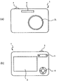
図11に、撮影レンズZLとして上記ズームレンズを備えたデジタルスチルカメラ1(光学機器)を示す。このデジタルスチルカメラ1は、不図示の電源釦を押すと、撮影レンズZLの不図示のシャッタが開放されて、撮影レンズZLで被写体(物体)からの光が集光され、像面I(図1参照)に配置された(例えば、CCDやCMOS等からなる)撮像素子に結像される。撮像素子に結像された被写体像は、デジタルスチルカメラ1の背後に配置された液晶モニター2に表示される。撮影者は、液晶モニター2を見ながら被写体像の構図を決めた後、レリーズ釦3を押し下げて被写体像を撮像素子で撮影し、不図示のメモリーに記録保存する。
FIG. 11 shows a digital still camera 1 (optical apparatus) provided with the zoom lens as a photographing lens ZL. In the digital
なお、このカメラ1には、被写体が暗い場合に補助光を発光する補助光発光部4、撮影レンズZLを広角端状態(W)から望遠端状態(T)にズーミングする際のワイド(W)−テレ(T)ボタン5、及び、デジタルスチルカメラ1の種々の条件設定等に使用するファンクションボタン6等が配置されている。
The
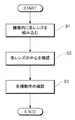
続いて、図12を参照しながら、上記構成のズームレンズの製造方法について説明する。まず、鏡筒内に各レンズ(図1ではレンズL11〜L32及びローパスフィルタLPF)を組み込む(ステップS1)。各レンズを鏡筒内に組み込む際、光軸に沿った順にレンズを1つずつ鏡筒内に組み込んでもよく、一部または全てのレンズを保持部材で一体保持してから鏡筒部材と組み立ててもよい。次に、鏡筒内に各レンズが組み込まれた後、鏡筒内に各レンズが組み込まれた状態で物体の像が形成されるか、すなわち各レンズの中心が揃っているかを確認する(ステップS2)。続いて、ズームレンズの各種動作を確認する(ステップS3)。各種動作の一例としては、広角端状態から望遠端状態への変倍を行う変倍動作、遠距離物体から近距離物体への合焦を行うレンズが光軸方向に沿って移動する合焦動作などが挙げられる。なお、各種動作の確認順番は任意である。 Next, a method for manufacturing the zoom lens having the above configuration will be described with reference to FIG. First, each lens (lenses L11 to L32 and low-pass filter LPF in FIG. 1) is incorporated in the lens barrel (step S1). When assembling each lens in the lens barrel, the lenses may be incorporated in the lens barrel one by one in the order along the optical axis, and a part or all of the lenses are integrally held by the holding member and then assembled with the lens barrel member. Also good. Next, after each lens is incorporated in the lens barrel, it is confirmed whether an object image is formed in a state where each lens is incorporated in the lens barrel, that is, whether the centers of the lenses are aligned (step) S2). Subsequently, various operations of the zoom lens are confirmed (step S3). Examples of various operations include a zooming operation that zooms from the wide-angle end state to the telephoto end state, and a focusing operation that moves the lens that focuses from a long-distance object to a short-distance object along the optical axis direction. Etc. Note that the order of confirming the various operations is arbitrary.
以下、本実施形態に係る各実施例について、図面に基づいて説明する。以下に、表1〜表5を示すが、これらは第1実施例〜第5実施例における各諸元の表である。[レンズデータ]においては、面番号は光線の進行する方向に沿った物体側からのレンズ面の順序を、rは各レンズ面の曲率半径を、dは各光学面から次の光学面(又は像面)までの光軸上の距離である面間隔を、ndはd線(波長587.6nm)に対する屈折率を、νdはd線に対するアッベ数を示す。また、レンズ面が非球面である場合には、面番号に*印を付し、曲率半径rの欄には近軸曲率半径を示す。なお、曲率半径の「0.0000」は平面又は開口を示す。また、空気の屈折率「1.00000」は省略する。 Hereinafter, each example according to the present embodiment will be described with reference to the drawings. Tables 1 to 5 are shown below, but these are tables of specifications in the first to fifth examples. In [Lens data], the surface number is the order of the lens surfaces from the object side along the direction in which the light beam travels, r is the radius of curvature of each lens surface, and d is the next optical surface from each optical surface (or The distance between the surfaces, which is the distance on the optical axis to the image plane), nd is the refractive index for the d-line (wavelength 587.6 nm), and νd is the Abbe number for the d-line. When the lens surface is aspherical, an asterisk is attached to the surface number, and the paraxial radius of curvature is indicated in the column of the radius of curvature r. The curvature radius “0.0000” indicates a plane or an opening. Also, the refractive index “1.00000” of air is omitted.
[非球面データ]には、[レンズデータ]に示した非球面について、その形状を次式(a)で示す。すなわち、光軸に垂直な方向の高さをyとし、非球面の頂点における接平面から高さyにおける非球面上の位置までの光軸に沿った距離(サグ量)をS(y)とし、基準球面の曲率半径(近軸曲率半径)をrとし、円錐係数をκとし、n次の非球面係数をCnとしたとき、以下の式(a)で示している。なお、各実施例において、2次の非球面係数C2は0であり、その記載を省略している。また、E-nは、×10-nを表す。例えば、1.234E-05=1.234×10⁻⁵である。 In [Aspherical data], the shape of the aspherical surface shown in [Lens data] is shown by the following equation (a). That is, y is the height in the direction perpendicular to the optical axis, and S (y) is the distance (sag amount) along the optical axis from the tangent plane at the apex of the aspheric surface to the position on the aspheric surface at height y. When the radius of curvature of the reference spherical surface (paraxial radius of curvature) is r, the conic coefficient is κ, and the n-th aspherical coefficient is Cn, the following equation (a) is given. In each embodiment, the secondary aspheric coefficient C2 is 0, and the description thereof is omitted. E-n represents x10 -n. For example, 1.234E-05 = 1.234 × 10 −5 .
S(y)=(y2/r)/{1+(1−κ・y2/r2)1/2}
+C4×y4+C6×y6+C8×y8+C10×y10 …(a)
S (y) = (y 2 / r) / {1+ (1−κ · y 2 / r 2 ) 1/2 }
+ C4 × y 4 + C6 × y 6 + C8 × y 8 + C10 × y 10 (a)
[可変間隔データ]において、広角端状態、中間焦点距離状態及び望遠端状態の各状態における、di(但し、iは整数)は第i面と第(i+1)面の可変間隔を示す。[各群焦点距離]において、各群の初面及び焦点距離を示す。[条件式]において、上記の条件式(1)〜(6)に対応する値を示す。 In [variable interval data], di (where i is an integer) in each of the wide-angle end state, the intermediate focal length state, and the telephoto end state indicates a variable interval between the i-th surface and the (i + 1) -th surface. In [Each Group Focal Length], the initial surface and focal length of each group are shown. In [Conditional Expression], values corresponding to the conditional expressions (1) to (6) are shown.
なお、表中において、焦点距離f、曲率半径r、面間隔d、その他の長さの単位は、一般に「mm」が使われている。但し、光学系は、比例拡大又は比例縮小しても同等の光学性能が得られるので、単位は「mm」に限定されることなく、他の適当な単位を用いることが可能である。 In the table, “mm” is generally used as the unit of focal length f, radius of curvature r, surface interval d, and other lengths. However, since the optical system can obtain the same optical performance even when proportionally enlarged or proportionally reduced, the unit is not limited to “mm”, and other appropriate units can be used.
以上の表の説明は、全ての実施例において適用されるものである。 The description in the above table applies to all the embodiments.
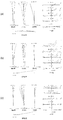
(第1実施例)
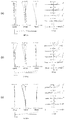
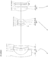
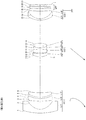
第1実施例について、図1、図2及び表1を用いて説明する。図1は、第1実施例のレンズ構成図及びズーム軌跡を示したものである。図1に示すように、第1実施例に係るレンズ系は、光軸に沿って物体側から順に並んだ、負の屈折力を持つ第1レンズ群G1と、正の屈折力を持つ第2レンズ群G2と、正の屈折力を持つ第3レンズ群G3とを有する。
(First embodiment)
A first embodiment will be described with reference to FIGS. 1 and 2 and Table 1. FIG. FIG. 1 shows a lens configuration diagram and zoom locus of the first embodiment. As shown in FIG. 1, the lens system according to the first example includes a first lens group G1 having negative refractive power, which is arranged in order from the object side along the optical axis, and a second lens having positive refractive power. It has a lens group G2 and a third lens group G3 having a positive refractive power.
第1レンズ群G1は、光軸に沿って物体側から順に並んだ、物体側に凸面を向けた2枚の凹メニスカスレンズL11,L12と、物体側に凸面を向けた凸メニスカスレンズL13とから構成される。 The first lens group G1 is composed of two concave meniscus lenses L11 and L12 having a convex surface facing the object side and a convex meniscus lens L13 having a convex surface facing the object side, which are arranged in order from the object side along the optical axis. Composed.
第2レンズ群G2は、光軸に沿って物体側から順に並んだ、物体側に凸面を向けた凸メニスカスレンズL21と、物体側に凸面を向けた凸メニスカスレンズL22と物体側に凸面を向けた凹メニスカスレンズL23との接合レンズと、両凸形状の凸レンズL24とから構成される。 The second lens group G2 is arranged in order from the object side along the optical axis, the convex meniscus lens L21 having a convex surface facing the object side, the convex meniscus lens L22 having the convex surface facing the object side, and the convex surface facing the object side. The lens is composed of a cemented lens with a concave meniscus lens L23 and a biconvex convex lens L24.
第3レンズ群G3は、光軸に沿って物体側から順に並んだ、両凸形状の凸レンズL31と像面側に凸面を向けた凹メニスカスレンズL32との接合レンズから構成される。 The third lens group G3 is composed of a cemented lens composed of a biconvex convex lens L31 and a concave meniscus lens L32 having a convex surface directed toward the image plane, which are arranged in order from the object side along the optical axis.
なお、第1レンズ群G1と第2レンズ群G2との間には、光量を調節するための開口絞りSが配置されている。 An aperture stop S for adjusting the amount of light is disposed between the first lens group G1 and the second lens group G2.
また、第3レンズ群G3と像面Iとの間には、像面Iに配設されるCCD等の固体撮像素子の限界解像以上の空間周波数をカットするためのローパスフィルタLPFが配置されている。 Further, a low-pass filter LPF for cutting a spatial frequency higher than the limit resolution of a solid-state imaging device such as a CCD disposed on the image plane I is disposed between the third lens group G3 and the image plane I. ing.
本実施例のズームレンズは、広角端状態から望遠端状態へのズーミングに際して、第1レンズ群G1、第2レンズ群G2及び第3レンズ群G3が移動する。また、開口絞りSは第2レンズ群G2と共に移動する。 In the zoom lens of this embodiment, the first lens group G1, the second lens group G2, and the third lens group G3 move during zooming from the wide-angle end state to the telephoto end state. The aperture stop S moves together with the second lens group G2.
以下の表1に、第1実施例における各諸元の表を示す。なお、表1における面番号1〜21は、図1に示す面1〜21に対応している。なお、第1実施例では、第2面、第10面及び第14面が非球面形状に形成されている。 Table 1 below shows a table of specifications in the first embodiment. In addition, the surface numbers 1-21 in Table 1 respond | correspond to the surfaces 1-21 shown in FIG. In the first embodiment, the second surface, the tenth surface, and the fourteenth surface are formed in an aspheric shape.
(表1)
[レンズデータ]
面番号 r d nd νd
1 32.4359 2.0 1.76802 49.23
*2 5.8278 4.5
3 506.9991 1.3 1.83400 37.17
4 20.3948 0.7
5 15.0456 2.4 1.84666 23.78
6 100.4482 (D6)
7 0.0000 0.1 (開口絞り)
8 6.9268 1.8 1.61800 63.38
9 21.0107 0.2
*10 11.703 1.8 1.69350 53.18
11 22.9271 0.9 1.75520 27.52
12 6.4040 0.9
13 69.2516 1.6 1.49589 82.24
*14 -9.8940 (D14)
15 13.4696 3.3 1.60300 65.47
16 -17.9388 0.8 1.84666 23.78
17 -953.1526 (D17)
18 0.0000 0.5 1.51633 64.14
19 0.0000 0.5
20 0.0000 0.5 1.51633 64.14
21 0.0000 0.6
[非球面データ]
第2面
κ = 0.15
C4 = 1.5903E-04
C6 = 6.2916E-07
C8 = 2.9804E-08
C10 = -9.4209E-11
第10面
κ = 1.00
C4 = -4.3230E-04
C6 = -3.9119E-06
C8 = 0.0000E+00
C10 = 0.0000E+00
第14面
κ = 1.00
C4 = -9.9563E-05
C6 = -1.1189E-06
C8 = 0.0000E+00
C10 = 0.0000E+00
[可変間隔データ]
広角端 中間焦点距離 望遠端
f 5.30 9.96 18.73
D6 17.25 6.78 0.79
D14 8.73 17.03 30.77
D17 2.30 1.55 1.55
空気換算BF 4.06 3.31 3.31
空気換算全長 52.34 49.41 57.17
[各群焦点距離]
群初面 群焦点距離
第1レンズ群 1 -11.50
第2レンズ群 8 14.13
第3レンズ群 15 30.09
[条件式]
条件式(1) (−f1)/f2 = 0.81
条件式(2) (−f1)/ft = 0.61
条件式(3) (R33+R31)/(R33−R31) = 0.97
条件式(4) n12 = 1.8340
条件式(5) ν12 = 37.2
条件式(6) (−f1)/fw = 2.17
(Table 1)
[Lens data]
Surface number r d nd νd
1 32.4359 2.0 1.76802 49.23
* 2 5.8278 4.5
3 506.9991 1.3 1.83400 37.17
4 20.3948 0.7
5 15.0456 2.4 1.84666 23.78
6 100.4482 (D6)
7 0.0000 0.1 (aperture stop)
8 6.9268 1.8 1.61800 63.38
9 21.0107 0.2
* 10 11.703 1.8 1.69350 53.18
11 22.9271 0.9 1.75520 27.52
12 6.4040 0.9
13 69.2516 1.6 1.49589 82.24
* 14 -9.8940 (D14)
15 13.4696 3.3 1.60300 65.47
16 -17.9388 0.8 1.84666 23.78
17 -953.1526 (D17)
18 0.0000 0.5 1.51633 64.14
19 0.0000 0.5
20 0.0000 0.5 1.51633 64.14
21 0.0000 0.6
[Aspherical data]
Second surface κ = 0.15
C4 = 1.5903E-04
C6 = 6.2916E-07
C8 = 2.9804E-08
C10 = -9.4209E-11
10th surface κ = 1.00
C4 = -4.3230E-04
C6 = -3.9119E-06
C8 = 0.0000E + 00
C10 = 0.0000E + 00
14th surface κ = 1.00
C4 = -9.9563E-05
C6 = -1.1189E-06
C8 = 0.0000E + 00
C10 = 0.0000E + 00
[Variable interval data]
Wide angle end Intermediate focal length Telephoto end f 5.30 9.96 18.73
D6 17.25 6.78 0.79
D14 8.73 17.03 30.77
D17 2.30 1.55 1.55
Air conversion BF 4.06 3.31 3.31
Air equivalent total length 52.34 49.41 57.17
[Each group focal length]
Group first surface Group focal length First lens group 1 -11.50
[Conditional expression]
Conditional expression (1) (−f1) /f2=0.81
Conditional expression (2) (−f1) /ft=0.61
Conditional expression (3) (R33 + R31) / (R33-R31) = 0.97
Conditional expression (4) n12 = 1.8340
Conditional expression (5) ν12 = 37.2
Conditional expression (6) (−f1) /fw=2.17
表1に示す諸元の表から、本実施例に係るズームレンズでは、上記条件式(1)〜(6)を全て満たすことが分かる。 From the table of specifications shown in Table 1, it can be seen that the zoom lens according to the present example satisfies all the conditional expressions (1) to (6).
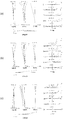
図2は、第1実施例の諸収差図(球面収差、非点収差、歪曲収差、倍率色収差及びコマ収差)であり、(a)は広角端状態における無限遠合焦状態での諸収差図であり、(b)は中間焦点距離状態における無限遠合焦状態での諸収差であり、(c)は望遠端状態における無限遠合焦状態での諸収差である。各収差図において、FNOはFナンバーを、Aは画角を示す。なお、球面収差図において、実線は球面収差を、破線は正弦条件を示す。また、非点収差図において、実線はサジタル像面を示し、破線はメリジオナル像面を示す。また、コマ収差図においては、メリジオナルコマを示す。また、dはd線(波長587.6nm)、gはg線(波長435.8nm)に対する諸収差を、記載のないものはd線に対する諸収差をそれぞれ示す。以上の収差図の説明は、他の実施例においても同様とし、その説明を省略する。 FIG. 2 is a diagram showing various aberrations (spherical aberration, astigmatism, distortion, lateral chromatic aberration, and coma aberration) of the first example, and (a) is a diagram showing various aberrations in the infinite focus state at the wide-angle end state. (B) shows various aberrations in the infinite focus state in the intermediate focal length state, and (c) shows various aberrations in the infinite focus state in the telephoto end state. In each aberration diagram, FNO represents an F number, and A represents an angle of view. In the spherical aberration diagram, the solid line indicates the spherical aberration, and the broken line indicates the sine condition. In the astigmatism diagram, the solid line indicates the sagittal image plane, and the broken line indicates the meridional image plane. The coma aberration diagram shows meridional coma. Further, d indicates various aberrations with respect to the d-line (wavelength 587.6 nm), g indicates various aberrations with respect to the g-line (wavelength 435.8 nm), and those not described indicate various aberrations with respect to the d-line. The explanation of the above aberration diagrams is the same in the other examples, and the explanation is omitted.
各収差図から明らかなように、第1実施例では、広角端状態から望遠端状態までの各焦点距離状態において、諸収差が良好に補正され、優れた結像性能を有することが分かる。 As is apparent from the respective aberration diagrams, in the first example, it is understood that various aberrations are well corrected and excellent imaging performance is obtained in each focal length state from the wide-angle end state to the telephoto end state.
(第2実施例)
第2実施例について、図3、図4及び表2を用いて説明する。図3は、第2実施例のレンズ構成図及びズーム軌跡を示したものである。図3に示すように、第2実施例に係るレンズ系は、光軸に沿って物体側から順に並んだ、負の屈折力を持つ第1レンズ群G1と、正の屈折力を持つ第2レンズ群G2と、正の屈折力を持つ第3レンズ群G3とを有する。
(Second embodiment)
The second embodiment will be described with reference to FIGS. 3 and 4 and Table 2. FIG. FIG. 3 shows a lens configuration diagram and zoom locus of the second embodiment. As shown in FIG. 3, the lens system according to the second example includes a first lens group G1 having a negative refractive power arranged in order from the object side along the optical axis and a second lens group having a positive refractive power. It has a lens group G2 and a third lens group G3 having a positive refractive power.
第1レンズ群G1は、光軸に沿って物体側から順に並んだ、物体側に凸面を向けた凹メニスカスレンズL11と、両凹レンズL12と、両凸形状の凸レンズL13とから構成される。 The first lens group G1 is composed of a concave meniscus lens L11 having a convex surface facing the object side, a biconcave lens L12, and a biconvex convex lens L13 arranged in order from the object side along the optical axis.
第2レンズ群G2は、光軸に沿って物体側から順に並んだ、物体側に凸面を向けた凸メニスカスレンズL21と、物体側に凸面を向けた凸メニスカスレンズL22と物体側に凸面を向けた凹メニスカスレンズL23との接合レンズと、両凸形状の凸レンズL24とから構成される。 The second lens group G2 is arranged in order from the object side along the optical axis, the convex meniscus lens L21 having a convex surface facing the object side, the convex meniscus lens L22 having the convex surface facing the object side, and the convex surface facing the object side. The lens is composed of a cemented lens with a concave meniscus lens L23 and a biconvex convex lens L24.
第3レンズ群G3は、光軸に沿って物体側から順に並んだ、両凸形状の凸レンズL31と像面側に凸面を向けた凹メニスカスレンズL32との接合レンズから構成される。 The third lens group G3 is composed of a cemented lens composed of a biconvex convex lens L31 and a concave meniscus lens L32 having a convex surface directed toward the image plane, which are arranged in order from the object side along the optical axis.
なお、第1レンズ群G1と第2レンズ群G2との間には、光量を調節するための開口絞りSが配置されている。 An aperture stop S for adjusting the amount of light is disposed between the first lens group G1 and the second lens group G2.
また、第3レンズ群G3と像面Iとの間には、像面Iに配設されるCCD等の固体撮像素子の限界解像以上の空間周波数をカットするためのローパスフィルタLPFが配置されている。 Further, a low-pass filter LPF for cutting a spatial frequency higher than the limit resolution of a solid-state imaging device such as a CCD disposed on the image plane I is disposed between the third lens group G3 and the image plane I. ing.
本実施例のズームレンズは、広角端状態から望遠端状態へのズーミングに際して、第1レンズ群G1、第2レンズ群G2及び第3レンズ群G3が移動する。また、開口絞りSは第2レンズ群G2と共に移動する。 In the zoom lens of this embodiment, the first lens group G1, the second lens group G2, and the third lens group G3 move during zooming from the wide-angle end state to the telephoto end state. The aperture stop S moves together with the second lens group G2.
以下の表2に、第2実施例における各諸元の表を示す。なお、表2における面番号1〜21は、図3に示す面1〜21に対応している。なお、第2実施例では、第2面、第8面及び第9面が非球面形状に形成されている。
Table 2 below shows a table of specifications in the second embodiment. The
(表2)
[レンズデータ]
面番号 r d nd νd
1 32.1966 1.6 1.80139 45.46
*2 5.3601 5.1
3 -34.3917 1.1 1.90265 35.71
4 64.9979 0.5
5 20.4083 1.8 1.84666 23.78
6 -237.8085 (D6)
7 0.0000 0.1 (開口絞り)
*8 6.2133 1.7 1.59201 67.05
*9 33.0469 0.1
10 12.0035 1.8 1.72916 54.66
11 42.924 0.9 1.80384 33.89
12 5.4641 0.9
13 19.9685 1.6 1.49782 82.56
14 -12.1899 (D14)
15 14.4382 3.3 1.618 63.38
16 -13.8037 0.8 1.86074 23.06
17 -110.0291 (D17)
18 0.0000 0.5 1.51633 64.14
19 0.0000 0.5
20 0.0000 0.5 1.51633 64.14
21 0.0000 0.6
[非球面データ]
第2面
κ = 0.15
C4 = 1.9910E-04
C6 = 1.3929E-06
C8 = 3.1173E-08
C10 = 1.6552E-10
第8面
κ = 0.74
C4 = -1.1798E-04
C6 = -1.6035E-06
C8 = 0.0000E+00
C10 = 0.0000E+00
第9面
κ = 1.00
C4 = 1.4311E-04
C6 = -1.2251E-06
C8 = 0.0000E+00
C10 = 0.0000E+00
[可変間隔データ]
広角端 中間焦点距離 望遠端
f 5.08 9.30 17.30
D6 16.39 6.59 0.89
D14 7.36 14.70 27.14
D17 2.32 1.65 1.24
空気換算BF 4.07 3.41 3.00
空気換算全長 49.53 46.40 52.73
[各群焦点距離]
群初面 群焦点距離
第1レンズ群 1 -11.13
第2レンズ群 8 13.39
第3レンズ群 15 29.58
[条件式]
条件式(1) (−f1)/f2 = 0.83
条件式(2) (−f1)/ft = 0.64
条件式(3) (R33+R31)/(R33−R31) = 0.77
条件式(4) n12 = 1.9027
条件式(5) ν12 = 35.7
条件式(6) (−f1)/fw = 2.19
(Table 2)
[Lens data]
Surface number r d nd νd
1 32.1966 1.6 1.80139 45.46
* 2 5.3601 5.1
3 -34.3917 1.1 1.90265 35.71
4 64.9979 0.5
5 20.4083 1.8 1.84666 23.78
6 -237.8085 (D6)
7 0.0000 0.1 (Aperture stop)
* 8 6.2133 1.7 1.59201 67.05
* 9 33.0469 0.1
10 12.0035 1.8 1.72916 54.66
11 42.924 0.9 1.80384 33.89
12 5.4641 0.9
13 19.9685 1.6 1.49782 82.56
14 -12.1899 (D14)
15 14.4382 3.3 1.618 63.38
16 -13.8037 0.8 1.86074 23.06
17 -110.0291 (D17)
18 0.0000 0.5 1.51633 64.14
19 0.0000 0.5
20 0.0000 0.5 1.51633 64.14
21 0.0000 0.6
[Aspherical data]
Second surface κ = 0.15
C4 = 1.9910E-04
C6 = 1.3929E-06
C8 = 3.1173E-08
C10 = 1.6552E-10
8th surface κ = 0.74
C4 = -1.1798E-04
C6 = -1.6035E-06
C8 = 0.0000E + 00
C10 = 0.0000E + 00
9th surface κ = 1.00
C4 = 1.4311E-04
C6 = -1.2251E-06
C8 = 0.0000E + 00
C10 = 0.0000E + 00
[Variable interval data]
Wide angle end Intermediate focal length Telephoto end f 5.08 9.30 17.30
D6 16.39 6.59 0.89
D14 7.36 14.70 27.14
D17 2.32 1.65 1.24
Air conversion BF 4.07 3.41 3.00
Total air equivalent 49.53 46.40 52.73
[Each group focal length]
Group first surface Group focal length First lens group 1 -11.13
[Conditional expression]
Conditional expression (1) (−f1) /f2=0.83
Conditional expression (2) (−f1) /ft=0.64
Conditional expression (3) (R33 + R31) / (R33-R31) = 0.77
Conditional expression (4) n12 = 1.9027
Conditional expression (5) ν12 = 35.7
Conditional expression (6) (−f1) /fw=2.19
表2に示す諸元の表から、本実施例に係るズームレンズでは、上記条件式(1)〜(6)を全て満たすことが分かる。 From the table of specifications shown in Table 2, it can be seen that the zoom lens according to the present example satisfies all the conditional expressions (1) to (6).
図4は、第2実施例の諸収差図(球面収差、非点収差、歪曲収差、倍率色収差及びコマ収差)であり、(a)は広角端状態における無限遠合焦状態での諸収差図であり、(b)は中間焦点距離状態における無限遠合焦状態での諸収差であり、(c)は望遠端状態における無限遠合焦状態での諸収差である。各収差図から明らかなように、第2実施例では、広角端状態から望遠端状態までの各焦点距離状態において、諸収差が良好に補正され、優れた結像性能を有することが分かる。 FIG. 4 is a diagram showing various aberrations (spherical aberration, astigmatism, distortion aberration, lateral chromatic aberration and coma aberration) of the second example, and (a) is a diagram showing various aberrations in the infinite focus state at the wide-angle end state. (B) shows various aberrations in the infinite focus state in the intermediate focal length state, and (c) shows various aberrations in the infinite focus state in the telephoto end state. As is apparent from the respective aberration diagrams, in the second embodiment, it is understood that various aberrations are favorably corrected and excellent imaging performance is obtained in each focal length state from the wide-angle end state to the telephoto end state.
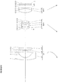
(第3実施例)
第3実施例について、図5、図6及び表3を用いて説明する。図5は、第3実施例のレンズ構成図及びズーム軌跡を示したものである。図5に示すように、第3実施例に係るレンズ系は、光軸に沿って物体側から順に並んだ、負の屈折力を持つ第1レンズ群G1と、正の屈折力を持つ第2レンズ群G2と、正の屈折力を持つ第3レンズ群G3とを有する。
(Third embodiment)
A third embodiment will be described with reference to FIGS. 5 and 6 and Table 3. FIG. FIG. 5 shows a lens configuration diagram and zoom locus of the third embodiment. As shown in FIG. 5, the lens system according to the third example includes a first lens group G1 having negative refractive power arranged in order from the object side along the optical axis, and a second lens group having positive refractive power. It has a lens group G2 and a third lens group G3 having a positive refractive power.
第1レンズ群G1は、光軸に沿って物体側から順に並んだ、物体側に凸面を向けた2枚の凹メニスカスレンズL11,L12と、物体側に凸面を向けた凸メニスカスレンズL13とから構成される。 The first lens group G1 is composed of two concave meniscus lenses L11, L12 having a convex surface facing the object side and a convex meniscus lens L13 having a convex surface facing the object side, which are arranged in order from the object side along the optical axis. Composed.
第2レンズ群G2は、光軸に沿って物体側から順に並んだ、物体側に凸面を向けた凸メニスカスレンズL21と、物体側に凸面を向けた凸メニスカスレンズL22と物体側に凸面を向けた凹メニスカスレンズL23との接合レンズと、両凸形状の凸レンズL24とから構成される。 The second lens group G2 is arranged in order from the object side along the optical axis, the convex meniscus lens L21 having a convex surface facing the object side, the convex meniscus lens L22 having the convex surface facing the object side, and the convex surface facing the object side. The lens is composed of a cemented lens with a concave meniscus lens L23 and a biconvex convex lens L24.
第3レンズ群G3は、光軸に沿って物体側から順に並んだ、両凸形状の凸レンズL31と両凹レンズL32との接合レンズから構成される。 The third lens group G3 is composed of a cemented lens of a biconvex convex lens L31 and a biconcave lens L32 arranged in order from the object side along the optical axis.
なお、第1レンズ群G1と第2レンズ群G2との間には、光量を調節するための開口絞りSが配置されている。 An aperture stop S for adjusting the amount of light is disposed between the first lens group G1 and the second lens group G2.
また、第3レンズ群G3と像面Iとの間には、像面Iに配設されるCCD等の固体撮像素子の限界解像以上の空間周波数をカットするためのローパスフィルタLPFが配置されている。 Further, a low-pass filter LPF for cutting a spatial frequency higher than the limit resolution of a solid-state imaging device such as a CCD disposed on the image plane I is disposed between the third lens group G3 and the image plane I. ing.
本実施例のズームレンズは、広角端状態から望遠端状態へのズーミングに際して、第1レンズ群G1、第2レンズ群G2及び第3レンズ群G3が移動する。また、開口絞りSは第2レンズ群G2と共に移動する。 In the zoom lens of this embodiment, the first lens group G1, the second lens group G2, and the third lens group G3 move during zooming from the wide-angle end state to the telephoto end state. The aperture stop S moves together with the second lens group G2.
以下の表3に、第3実施例における各諸元の表を示す。なお、表3における面番号1〜21は、図5に示す面1〜21に対応している。なお、第3実施例では、第2面、第10面及び第14面が非球面形状に形成されている。
Table 3 below shows a table of specifications in the third embodiment. The
(表3)
[レンズデータ]
面番号 r d nd νd
1 34.2527 2.0 1.80139 45.46
*2 6.1327 4.3
3 63.5113 1.2 1.88300 40.8
4 17.5737 0.5
5 13.6765 2.1 1.84666 23.78
6 67.7280 (D6)
7 0.0000 0.1 (開口絞り)
8 6.0315 1.5 1.64000 60.09
9 16.2232 0.2
*10 8.7852 1.2 1.80139 45.46
11 20.8083 0.8 1.74077 27.79
12 4.9449 1.1
13 87.3663 1.3 1.49782 82.56
*14 -10.2767 (D14)
15 12.6665 3.3 1.61800 63.38
16 -16.9392 0.8 1.84666 23.78
17 220.0172 (D17)
18 0.0000 0.5 1.51633 64.14
19 0.0000 0.5
20 0.0000 0.5 1.51633 64.14
21 0.0000 0.6
[非球面データ]
第2面
κ = 0.12
C4 = 1.5629E-04
C6 = 5.9866E-07
C8 = 2.0048E-08
C10 = -4.8191E-11
第10面
κ = -0.42
C4 = -2.1797E-04
C6 = -8.6870E-06
C8 = 0.0000E+00
C10 = 0.0000E+00
第14面
κ = 1.00
C4 = -1.8670E-04
C6 = -1.3723E-05
C8 = 0.0000E+00
C10 = 0.0000E+00
[可変間隔データ]
広角端 中間焦点距離 望遠端
f 5.00 9.35 18.30
D6 18.27 6.79 0.48
D14 7.59 13.75 26.66
D17 1.72 1.72 1.26
空気換算BF 3.48 3.48 3.02
空気換算全長 49.69 44.37 50.50
[各群焦点距離]
群初面 群焦点距離
第1レンズ群 1 -12.14
第2レンズ群 8 13.20
第3レンズ群 15 30.09
[条件式]
条件式(1) (−f1)/f2 = 0.92
条件式(2) (−f1)/ft = 0.66
条件式(3) (R33+R31)/(R33−R31) = 1.12
条件式(4) n12 = 1.8830
条件式(5) ν12 = 40.8
条件式(6) (−f1)/fw = 2.43
(Table 3)
[Lens data]
Surface number r d nd νd
1 34.2527 2.0 1.80139 45.46
* 2 6.1327 4.3
3 63.5113 1.2 1.88300 40.8
4 17.5737 0.5
5 13.6765 2.1 1.84666 23.78
6 67.7280 (D6)
7 0.0000 0.1 (Aperture stop)
8 6.0315 1.5 1.64000 60.09
9 16.2232 0.2
* 10 8.7852 1.2 1.80139 45.46
11 20.8083 0.8 1.74077 27.79
12 4.9449 1.1
13 87.3663 1.3 1.49782 82.56
* 14 -10.2767 (D14)
15 12.6665 3.3 1.61800 63.38
16 -16.9392 0.8 1.84666 23.78
17 220.0172 (D17)
18 0.0000 0.5 1.51633 64.14
19 0.0000 0.5
20 0.0000 0.5 1.51633 64.14
21 0.0000 0.6
[Aspherical data]
Second surface κ = 0.12
C4 = 1.5629E-04
C6 = 5.9866E-07
C8 = 2.0048E-08
C10 = -4.8191E-11
10th surface κ = -0.42
C4 = -2.1797E-04
C6 = -8.6870E-06
C8 = 0.0000E + 00
C10 = 0.0000E + 00
14th surface κ = 1.00
C4 = -1.8670E-04
C6 = -1.3723E-05
C8 = 0.0000E + 00
C10 = 0.0000E + 00
[Variable interval data]
Wide angle end Intermediate focal length Telephoto end f 5.00 9.35 18.30
D6 18.27 6.79 0.48
D14 7.59 13.75 26.66
D17 1.72 1.72 1.26
Air conversion BF 3.48 3.48 3.02
Total air equivalent 49.69 44.37 50.50
[Each group focal length]
Group first surface Group focal length First lens group 1 -12.14
[Conditional expression]
Conditional expression (1) (−f1) /f2=0.92
Conditional expression (2) (−f1) /ft=0.66
Conditional expression (3) (R33 + R31) / (R33-R31) = 1.12
Conditional expression (4) n12 = 1.8830
Conditional expression (5) ν12 = 40.8
Conditional expression (6) (−f1) /fw=2.43
表3に示す諸元の表から、本実施例に係るズームレンズでは、上記条件式(1)〜(6)を全て満たすことが分かる。 From the table of specifications shown in Table 3, it can be seen that the zoom lens according to the present example satisfies all the conditional expressions (1) to (6).
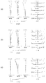
図6は、第3実施例の諸収差図(球面収差、非点収差、歪曲収差、倍率色収差及びコマ収差)であり、(a)は広角端状態における無限遠合焦状態での諸収差図であり、(b)は中間焦点距離状態における無限遠合焦状態での諸収差であり、(c)は望遠端状態における無限遠合焦状態での諸収差である。各収差図から明らかなように、第3実施例では、広角端状態から望遠端状態までの各焦点距離状態において、諸収差が良好に補正され、優れた結像性能を有することが分かる。 FIG. 6 is a diagram showing various aberrations (spherical aberration, astigmatism, distortion, lateral chromatic aberration, and coma aberration) of the third example, and (a) is a diagram showing various aberrations in the infinite focus state at the wide-angle end state. (B) shows various aberrations in the infinite focus state in the intermediate focal length state, and (c) shows various aberrations in the infinite focus state in the telephoto end state. As is apparent from the respective aberration diagrams, in the third example, it is understood that various aberrations are well corrected and excellent imaging performance is obtained in each focal length state from the wide-angle end state to the telephoto end state.
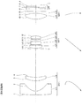
(第4実施例)
第4実施例について、図7、図8及び表4を用いて説明する。図7は、第4実施例のレンズ構成図及びズーム軌跡を示したものである。図7に示すように、第4実施例に係るレンズ系は、光軸に沿って物体側から順に並んだ、負の屈折力を持つ第1レンズ群G1と、正の屈折力を持つ第2レンズ群G2と、正の屈折力を持つ第3レンズ群G3とを有する。
(Fourth embodiment)
A fourth embodiment will be described with reference to FIGS. 7 and 8 and Table 4. FIG. FIG. 7 shows a lens configuration diagram and zoom locus of the fourth embodiment. As shown in FIG. 7, the lens system according to the fourth example includes a first lens group G1 having negative refractive power, which is arranged in order from the object side along the optical axis, and a second lens having positive refractive power. It has a lens group G2 and a third lens group G3 having a positive refractive power.
第1レンズ群G1は、光軸に沿って物体側から順に並んだ、物体側に凸面を向けた2枚の凹メニスカスレンズL11,L12と、物体側に凸面を向けた凸メニスカスレンズL13とから構成される。 The first lens group G1 is composed of two concave meniscus lenses L11, L12 having a convex surface facing the object side and a convex meniscus lens L13 having a convex surface facing the object side, which are arranged in order from the object side along the optical axis. Composed.
第2レンズ群G2は、光軸に沿って物体側から順に並んだ、物体側に凸面を向けた凸メニスカスレンズL21と、物体側に凸面を向けた凸メニスカスレンズL22と物体側に凸面を向けた凹メニスカスレンズL23との接合レンズと、両凸形状の凸レンズL24とから構成される。 The second lens group G2 is arranged in order from the object side along the optical axis, the convex meniscus lens L21 having a convex surface facing the object side, the convex meniscus lens L22 having the convex surface facing the object side, and the convex surface facing the object side. The lens is composed of a cemented lens with a concave meniscus lens L23 and a biconvex convex lens L24.
第3レンズ群G3は、光軸に沿って物体側から順に並んだ、物体側に凸面を向けた凹メニスカスレンズL31と物体側に凸面を向けた凸メニスカスレンズL32との接合レンズから構成される。 The third lens group G3 is composed of a cemented lens of a concave meniscus lens L31 having a convex surface facing the object side and a convex meniscus lens L32 having a convex surface facing the object side, which are arranged in order from the object side along the optical axis. .
なお、第1レンズ群G1と第2レンズ群G2との間には、光量を調節するための開口絞りSが配置されている。 An aperture stop S for adjusting the amount of light is disposed between the first lens group G1 and the second lens group G2.
また、第3レンズ群G3と像面Iとの間には、像面Iに配設されるCCD等の固体撮像素子の限界解像以上の空間周波数をカットするためのローパスフィルタLPFが配置されている。 Further, a low-pass filter LPF for cutting a spatial frequency higher than the limit resolution of a solid-state imaging device such as a CCD disposed on the image plane I is disposed between the third lens group G3 and the image plane I. ing.
本実施例のズームレンズは、広角端状態から望遠端状態へのズーミングに際して、第1レンズ群G1及び第2レンズ群G2は移動し、開口絞りは第2レンズ群G2と共に移動する。また、ズーミングに際して、第3レンズ群G3は固定である。 In the zoom lens of this embodiment, the first lens group G1 and the second lens group G2 move during zooming from the wide-angle end state to the telephoto end state, and the aperture stop moves together with the second lens group G2. In zooming, the third lens group G3 is fixed.
以下の表4に、第4実施例における各諸元の表を示す。なお、表4における面番号1〜21は、図7に示す面1〜21に対応している。なお、第4実施例では、第2面、第9面及び第14面が非球面形状に形成されている。
Table 4 below shows a table of specifications in the fourth embodiment. The
(表4)
[レンズデータ]
面番号 r d nd νd
1 30.7572 2.0 1.76802 49.23
*2 5.8501 4.3
3 53.5149 1.3 1.83400 37.17
4 13.2469 0.7
5 11.9171 2.4 1.84666 23.78
6 44.7002 (D6)
7 0.0000 0.1 (開口絞り)
8 7.4888 1.8 1.61800 63.38
*9 23.2420 0.2
10 18.0656 1.8 1.69350 53.18
11 27.772 0.9 1.75520 27.52
12 8.1070 0.9
13 168.1139 1.6 1.49589 82.24
*14 -8.7901 (D14)
15 11.1164 0.8 1.80518 25.43
16 6.8262 4.0 1.61800 63.38
17 56.8935 (D17)
18 0.0000 0.5 1.51633 64.14
19 0.0000 0.5
20 0.0000 0.5 1.51633 64.14
21 0.0000 0.6
[非球面データ]
第2面
κ = 0.17
C4 = 1.5438E-04
C6 = 8.5975E-07
C8 = 2.2343E-08
C10 = 1.4787E-10
第9面
κ = 5.80
C4 = 4.0546E-04
C6 = 1.6161E-06
C8 = 0.0000E+00
C10 = 0.0000E+00
第14面
κ = 1.00
C4 = -7.1813E-05
C6 = -1.0023E-06
C8 = 0.0000E+00
C10 = 0.0000E+00
[可変間隔データ]
広角端 中間焦点距離 望遠端
f 5.30 9.92 18.55
D6 18.76 8.04 2.30
D14 12.13 20.73 36.82
D17 1.31 1.31 1.31
空気換算BF 3.07 3.07 3.07
空気換算全長 56.75 54.63 65.00
[各群焦点距離]
群初面 群焦点距離
第1レンズ群 1 -10.90
第2レンズ群 8 15.08
第3レンズ群 15 27.32
[条件式]
条件式(1) (−f1)/f2 = 0.72
条件式(2) (−f1)/ft = 0.59
条件式(3) (R33+R31)/(R33−R31) = 1.49
条件式(4) n12 = 1.8340
条件式(5) ν12 = 37.2
条件式(6) (−f1)/fw = 2.06
(Table 4)
[Lens data]
Surface number r d nd νd
1 30.7572 2.0 1.76802 49.23
* 2 5.8501 4.3
3 53.5149 1.3 1.83400 37.17
4 13.2469 0.7
5 11.9171 2.4 1.84666 23.78
6 44.7002 (D6)
7 0.0000 0.1 (Aperture stop)
8 7.4888 1.8 1.61800 63.38
* 9 23.2420 0.2
10 18.0656 1.8 1.69350 53.18
11 27.772 0.9 1.75520 27.52
12 8.1070 0.9
13 168.1139 1.6 1.49589 82.24
* 14 -8.7901 (D14)
15 11.1164 0.8 1.80518 25.43
16 6.8262 4.0 1.61800 63.38
17 56.8935 (D17)
18 0.0000 0.5 1.51633 64.14
19 0.0000 0.5
20 0.0000 0.5 1.51633 64.14
21 0.0000 0.6
[Aspherical data]
Second surface κ = 0.17
C4 = 1.5438E-04
C6 = 8.5975E-07
C8 = 2.2343E-08
C10 = 1.4787E-10
9th surface κ = 5.80
C4 = 4.0546E-04
C6 = 1.6161E-06
C8 = 0.0000E + 00
C10 = 0.0000E + 00
14th surface κ = 1.00
C4 = -7.1813E-05
C6 = -1.0023E-06
C8 = 0.0000E + 00
C10 = 0.0000E + 00
[Variable interval data]
Wide angle end Intermediate focal length Telephoto end f 5.30 9.92 18.55
D6 18.76 8.04 2.30
D14 12.13 20.73 36.82
D17 1.31 1.31 1.31
Air conversion BF 3.07 3.07 3.07
Air equivalent total length 56.75 54.63 65.00
[Each group focal length]
Group first surface Group focal length First lens group 1 -10.90
[Conditional expression]
Conditional expression (1) (−f1) /f2=0.72
Conditional expression (2) (−f1) /ft=0.59
Conditional expression (3) (R33 + R31) / (R33-R31) = 1.49
Conditional expression (4) n12 = 1.8340
Conditional expression (5) ν12 = 37.2
Conditional expression (6) (−f1) /fw=2.06
表4に示す諸元の表から、本実施例に係るズームレンズでは、上記条件式(1)〜(6)を全て満たすことが分かる。 From the table of specifications shown in Table 4, it can be seen that the zoom lens according to the present example satisfies all the conditional expressions (1) to (6).
図8は、第4実施例の諸収差図(球面収差、非点収差、歪曲収差、倍率色収差及びコマ収差)であり、(a)は広角端状態における無限遠合焦状態での諸収差図であり、(b)は中間焦点距離状態における無限遠合焦状態での諸収差であり、(c)は望遠端状態における無限遠合焦状態での諸収差である。各収差図から明らかなように、第4実施例では、広角端状態から望遠端状態までの各焦点距離状態において、諸収差が良好に補正され、優れた結像性能を有することが分かる。 FIG. 8 is a diagram showing various aberrations (spherical aberration, astigmatism, distortion, lateral chromatic aberration and coma aberration) of the fourth example, and (a) is a diagram showing various aberrations in the infinite focus state at the wide-angle end state. (B) shows various aberrations in the infinite focus state in the intermediate focal length state, and (c) shows various aberrations in the infinite focus state in the telephoto end state. As is apparent from the respective aberration diagrams, in the fourth example, it is understood that various aberrations are well corrected and excellent imaging performance is obtained in each focal length state from the wide-angle end state to the telephoto end state.
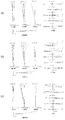
(第5実施例)
第5実施例について、図9、図10及び表5を用いて説明する。図9は、第5実施例のレンズ構成図及びズーム軌跡を示したものである。図9に示すように、第5実施例に係るレンズ系は、光軸に沿って物体側から順に並んだ、負の屈折力を持つ第1レンズ群G1と、正の屈折力を持つ第2レンズ群G2と、正の屈折力を持つ第3レンズ群G3とを有する。
(5th Example)
The fifth embodiment will be described with reference to FIGS. 9 and 10 and Table 5. FIG. FIG. 9 shows a lens configuration diagram and zoom locus of the fifth embodiment. As shown in FIG. 9, the lens system according to the fifth example includes a first lens group G1 having negative refractive power arranged in order from the object side along the optical axis, and a second lens group having positive refractive power. It has a lens group G2 and a third lens group G3 having a positive refractive power.
第1レンズ群G1は、光軸に沿って物体側から順に並んだ、物体側に凸面を向けた凹メニスカスレンズL11と、物体側に凸面を向けた凸メニスカスレンズL12とから構成される。 The first lens group G1 includes a concave meniscus lens L11 having a convex surface facing the object side and a convex meniscus lens L12 having a convex surface facing the object side, which are arranged in order from the object side along the optical axis.
第2レンズ群G2は、光軸に沿って物体側から順に並んだ、物体側に凸面を向けた凸メニスカスレンズL21と、物体側に凸面を向けた凸メニスカスレンズL22と物体側に凸面を向けた凹メニスカスレンズL23との接合レンズと、両凸形状の凸レンズL24とから構成される。 The second lens group G2 is arranged in order from the object side along the optical axis, the convex meniscus lens L21 having a convex surface facing the object side, the convex meniscus lens L22 having the convex surface facing the object side, and the convex surface facing the object side. The lens is composed of a cemented lens with a concave meniscus lens L23 and a biconvex convex lens L24.
第3レンズ群G3は、光軸に沿って物体側から順に並んだ、両凸形状の凸レンズL31と両凹レンズL32との接合レンズから構成される。 The third lens group G3 is composed of a cemented lens of a biconvex convex lens L31 and a biconcave lens L32 arranged in order from the object side along the optical axis.
なお、第1レンズ群G1と第2レンズ群G2との間には、光量を調節するための開口絞りSが配置されている。 An aperture stop S for adjusting the amount of light is disposed between the first lens group G1 and the second lens group G2.
また、第3レンズ群G3と像面Iとの間には、像面Iに配設されるCCD等の固体撮像素子の限界解像以上の空間周波数をカットするためのローパスフィルタLPFが配置されている。 Further, a low-pass filter LPF for cutting a spatial frequency higher than the limit resolution of a solid-state imaging device such as a CCD disposed on the image plane I is disposed between the third lens group G3 and the image plane I. ing.
本実施例のズームレンズは、広角端状態から望遠端状態へのズーミングに際して、第1レンズ群G1、第2レンズ群G2及び第3レンズ群G3が移動する。また、開口絞りSは第2レンズ群G2と共に移動する。 In the zoom lens of this embodiment, the first lens group G1, the second lens group G2, and the third lens group G3 move during zooming from the wide-angle end state to the telephoto end state. The aperture stop S moves together with the second lens group G2.
以下の表5に、第5実施例における各諸元の表を示す。なお、表5における面番号1〜19は、図9に示す面1〜19に対応している。なお、第5実施例では、第2面、第8面及び第12面が非球面形状に形成されている。 Table 5 below shows a table of specifications in the fifth embodiment. In addition, the surface numbers 1-19 in Table 5 respond | correspond to the surfaces 1-19 shown in FIG. In the fifth embodiment, the second surface, the eighth surface and the twelfth surface are formed in an aspherical shape.
(表5)
[レンズデータ]
面番号 r d nd νd
1 78.5982 1.8 1.6935 53.18
*2 4.4534 5.0
3 11.1548 1.7 1.92286 20.88
4 15.7514 (D4)
5 0.0000 0.1 (開口絞り)
6 6.4565 1.6 1.75500 52.29
7 44.4279 0.2
*8 72.4618 1.6 1.80139 45.46
9 154.3417 0.8 1.75520 27.52
10 6.5954 0.5
11 42.1347 1.4 1.49589 82.24
*12 -6.9616 (D12)
13 10.2314 2.9 1.60300 65.47
14 -14.5330 0.9 1.84666 23.78
15 177.4281 (D15)
16 0.0000 0.5 1.51633 64.14
17 0.0000 0.3
18 0.0000 0.5 1.51633 64.14
19 0.0000 0.6
[非球面データ]
第2面
κ = 0.07
C4 = 2.0292E-04
C6 = -5.0742E-06
C8 = 2.6416E-07
C10 = -4.0884E-09
第8面
κ = 1.00
C4 = -7.3661E-04
C6 = 9.9318E-06
C8 = 0.0000E+00
C10 = 0.0000E+00
第12面
κ = 1.00
C4 = -2.2550E-04
C6 = 1.4402E-05
C8 = 0.0000E+00
C10 = 0.0000E+00
[可変間隔データ]
広角端 中間焦点距離 望遠端
f 4.43 8.32 15.64
D6 13.94 5.19 0.20
D14 8.18 15.11 26.59
D17 1.28 0.65 0.65
空気換算BF 2.84 2.21 2.21
空気換算全長 43.47 41.02 47.50
[各群焦点距離]
群初面 群焦点距離
第1レンズ群 1 -9.60
第2レンズ群 6 11.80
第3レンズ群 13 25.13
[条件式]
条件式(1) (−f1)/f2 = 0.81
条件式(2) (−f1)/ft = 0.61
条件式(3) (R33+R31)/(R33−R31) = 1.12
条件式(6) (−f1)/fw = 2.17
(Table 5)
[Lens data]
Surface number r d nd νd
1 78.5982 1.8 1.6935 53.18
* 2 4.4534 5.0
3 11.1548 1.7 1.92286 20.88
4 15.7514 (D4)
5 0.0000 0.1 (Aperture stop)
6 6.4565 1.6 1.75500 52.29
7 44.4279 0.2
* 8 72.4618 1.6 1.80139 45.46
9 154.3417 0.8 1.75520 27.52
10 6.5954 0.5
11 42.1347 1.4 1.49589 82.24
* 12 -6.9616 (D12)
13 10.2314 2.9 1.60300 65.47
14 -14.5330 0.9 1.84666 23.78
15 177.4281 (D15)
16 0.0000 0.5 1.51633 64.14
17 0.0000 0.3
18 0.0000 0.5 1.51633 64.14
19 0.0000 0.6
[Aspherical data]
Second surface κ = 0.07
C4 = 2.0292E-04
C6 = -5.0742E-06
C8 = 2.6416E-07
C10 = -4.0884E-09
8th surface κ = 1.00
C4 = -7.3661E-04
C6 = 9.9318E-06
C8 = 0.0000E + 00
C10 = 0.0000E + 00
12th surface κ = 1.00
C4 = -2.2550E-04
C6 = 1.4402E-05
C8 = 0.0000E + 00
C10 = 0.0000E + 00
[Variable interval data]
Wide angle end Intermediate focal length Telephoto end f 4.43 8.32 15.64
D6 13.94 5.19 0.20
D14 8.18 15.11 26.59
D17 1.28 0.65 0.65
Air conversion BF 2.84 2.21 2.21
Total air equivalent 43.47 41.02 47.50
[Each group focal length]
Group first surface Group focal length First lens group 1 -9.60
[Conditional expression]
Conditional expression (1) (−f1) /f2=0.81
Conditional expression (2) (−f1) /ft=0.61
Conditional expression (3) (R33 + R31) / (R33-R31) = 1.12
Conditional expression (6) (−f1) /fw=2.17
表5に示す諸元の表から、本実施例に係るズームレンズでは、上記条件式(1)〜(3),(6)を満たすことが分かる。 From the table of specifications shown in Table 5, it can be seen that the zoom lens according to the present example satisfies the conditional expressions (1) to (3) and (6).
図10は、第5実施例の諸収差図(球面収差、非点収差、歪曲収差、倍率色収差及びコマ収差)であり、(a)は広角端状態における無限遠合焦状態での諸収差図であり、(b)は中間焦点距離状態における無限遠合焦状態での諸収差であり、(c)は望遠端状態における無限遠合焦状態での諸収差である。各収差図から明らかなように、第5実施例では、広角端状態から望遠端状態までの各焦点距離状態において、諸収差が良好に補正され、優れた結像性能を有することが分かる。 FIG. 10 is a diagram illustrating various aberrations (spherical aberration, astigmatism, distortion, lateral chromatic aberration, and coma aberration) of the fifth example, and (a) is a diagram illustrating various aberrations in the infinite focus state at the wide-angle end state. (B) shows various aberrations in the infinite focus state in the intermediate focal length state, and (c) shows various aberrations in the infinite focus state in the telephoto end state. As is apparent from each aberration diagram, in the fifth example, it is understood that various aberrations are well corrected and excellent imaging performance is obtained in each focal length state from the wide-angle end state to the telephoto end state.
なお、上述の実施形態において、以下に記載の内容は、光学性能を損なわない範囲で適宜採用可能である。 In the above-described embodiment, the following description can be appropriately adopted as long as the optical performance is not impaired.
上記実施例では、3群構成を示したが、4群、5群等の他の群構成にも適用可能である。また、最も物体側にレンズまたはレンズ群を追加した構成や、最も像側にレンズまたはレンズ群を追加した構成でも構わない。また、レンズ群とは、変倍時に変化する空気間隔で分離された、少なくとも1枚のレンズを有する部分を言う。 In the above embodiment, the three-group configuration is shown, but the present invention can also be applied to other group configurations such as the fourth group and the fifth group. Further, a configuration in which a lens or a lens group is added to the most object side, or a configuration in which a lens or a lens group is added to the most image side may be used. The lens group refers to a portion having at least one lens separated by an air interval that changes during zooming.
また、本実施形態においては、単独または複数のレンズ群、または部分レンズ群を光軸方向に移動させて、無限遠物体から近距離物体への合焦を行う合焦レンズ群としてもよい。この合焦レンズ群は、オートフォーカスにも適用でき、オートフォーカス用の(超音波モーター等を用いた)モーター駆動にも適している。特に、第3レンズ群を合焦レンズ群とするのが好ましい。 Further, in the present embodiment, a single lens group, a plurality of lens groups, or a partial lens group may be moved in the optical axis direction to be a focusing lens group that performs focusing from an object at infinity to a near object. This focusing lens group can be applied to autofocus, and is also suitable for driving a motor for autofocus (using an ultrasonic motor or the like). In particular, the third lens group is preferably a focusing lens group.
また、本実施形態において、レンズ群または部分レンズ群を光軸に垂直な方向に振動させ、または光軸を含む面内方向に回転移動(揺動)させて、手ブレによって生じる像ブレを補正する防振レンズ群としてもよい。特に、第2レンズ群の少なくとも一部を防振レンズ群とするのが好ましい。 In this embodiment, the lens group or the partial lens group is vibrated in a direction perpendicular to the optical axis, or rotated (oscillated) in an in-plane direction including the optical axis to correct image blur caused by camera shake. An anti-vibration lens group may be used. In particular, it is preferable that at least a part of the second lens group is an anti-vibration lens group.
また、本実施形態において、レンズ面は、球面または平面で形成されても、非球面で形成されても構わない。レンズ面が球面または平面の場合、レンズ加工及び組立調整が容易になり、加工及び組立調整の誤差による光学性能の劣化を防げるので好ましい。また、像面がずれた場合でも描写性能の劣化が少ないので好ましい。また、レンズ面が非球面の場合、非球面は、研削加工による非球面、ガラスを型で非球面形状に形成したガラスモールド非球面、ガラスの表面に樹脂を非球面形状に形成した複合型非球面のいずれの非球面でも構わない。なお、本実施形態では、非球面を3面以上用いるのが好ましい。また、レンズ面は回折面としてもよく、レンズを屈折率分布型レンズ(GRINレンズ)あるいはプラスチックレンズとしてもよい。 In the present embodiment, the lens surface may be formed as a spherical surface, a flat surface, or an aspheric surface. When the lens surface is a spherical surface or a flat surface, lens processing and assembly adjustment are facilitated, and optical performance deterioration due to errors in processing and assembly adjustment can be prevented. Further, even when the image plane is deviated, it is preferable because there is little deterioration in drawing performance. If the lens surface is aspherical, the aspherical surface is an aspherical surface by grinding, a glass mold aspherical surface that is formed of glass with an aspherical shape, or a composite type nonspherical surface that is formed of a resin on the surface of glass. Any aspherical surface may be used. In the present embodiment, it is preferable to use three or more aspheric surfaces. The lens surface may be a diffractive surface, and the lens may be a gradient index lens (GRIN lens) or a plastic lens.
また、本実施形態において、開口絞りは第2レンズ群近傍に配置されるのが好ましいが、開口絞りとしての部材を設けずにレンズ枠でその役割を代用してもよい。 In the present embodiment, the aperture stop is preferably disposed in the vicinity of the second lens group, but the role may be substituted by a lens frame without providing a member as the aperture stop.
また、本実施形態において、各レンズ面には、フレアやゴーストを軽減して高コントラストの高い光学性能を達成するために、広い波長域で高い透過率を有する反射防止膜を施してもよい。 In this embodiment, each lens surface may be provided with an antireflection film having a high transmittance in a wide wavelength region in order to reduce flare and ghost and achieve high optical performance with high contrast.
また、本実施形態のズームレンズ(変倍光学系)は、変倍比が3〜5程度である。 The zoom lens (variable magnification optical system) of the present embodiment has a magnification ratio of about 3 to 5.
また、本実施形態のズームレンズ(変倍光学系)は、第1レンズ群が、正レンズ成分を1つと負レンズ成分を2つ有するか、又は、正レンズ成分を1つと負レンズ成分を1つ有するのが好ましい。また、第2レンズ群が、正レンズ成分を2つと、負レンズ成分を1つ有するのが好ましい。また、第3レンズ群が、正レンズ成分を1つ有するのが好ましい。 In the zoom lens (variable magnification optical system) of the present embodiment, the first lens group has one positive lens component and two negative lens components, or one positive lens component and one negative lens component. It is preferable to have one. Further, it is preferable that the second lens group has two positive lens components and one negative lens component. The third lens group preferably has one positive lens component.
以上のように、本発明を分かりやすくするため、実施形態の構成要件を付して説明したが、本発明がこれに限定されるものではないことは言うまでもない。 As described above, in order to make the present invention easy to understand, the configuration requirements of the embodiment have been described, but it goes without saying that the present invention is not limited to this.
G1 第1レンズ群
G2 第2レンズ群
G3 第3レンズ群
S 開口絞り
I 像面
LPF ローパスフィルタ
1 デジタルスチルカメラ(光学機器)
ZL 撮影レンズ(ズームレンズ)
G1 First lens group G2 Second lens group G3 Third lens group S Aperture stop I Image plane LPF
ZL photography lens (zoom lens)
Claims (10)
広角端状態から望遠端状態へのズーミングに際し、前記第1レンズ群と前記第2レンズ群は移動し、前記開口絞りは前記第2レンズ群と共に移動し、
前記第3レンズ群は、球面レンズで構成された接合レンズ1枚を有し、
前記第1レンズ群の焦点距離をf1とし、前記第2レンズ群の焦点距離をf2としたとき、次式
0.60<(−f1)/f2<0.93
の条件を満足することを特徴とするズームレンズ。 A first lens group having negative refractive power, an aperture stop, a second lens group having positive refractive power, and a third lens group having positive refractive power, which are arranged in order from the object side along the optical axis. And
During zooming from the wide-angle end state to the telephoto end state, the first lens group and the second lens group move, and the aperture stop moves together with the second lens group,
The third lens group has one cemented lens composed of a spherical lens,
When the focal length of the first lens group is f1 and the focal length of the second lens group is f2, the following equation is given: 0.60 <(− f1) / f2 <0.93
A zoom lens that satisfies the following conditions.
0.45<(−f1)/ft<0.72
の条件を満足することを特徴とする請求項1に記載のズームレンズ。 When the combined focal length of the entire lens system in the telephoto end state is ft, the following formula 0.45 <(− f1) / ft <0.72
The zoom lens according to claim 1, wherein the following condition is satisfied.
0.15<(R33+R31)/(R33−R31)<5.00
の条件を満足することを特徴とする請求項1又は2に記載のズームレンズ。 When the radius of curvature of the lens surface closest to the object side of the third lens group is R31 and the radius of curvature of the lens surface closest to the image side of the third lens group is R33, the following expression 0.15 <(R33 + R31) / (R33-R31) <5.00
The zoom lens according to claim 1, wherein the zoom lens satisfies the following condition.
1.800<n12<2.300
の条件を満足することを特徴とする請求項1〜3のいずれか一項に記載のズームレンズ。 When the refractive index with respect to the d-line of the second concave lens from the object side of the first lens group is n12, the following expression 1.800 <n12 <2.300
The zoom lens according to claim 1, wherein the zoom lens satisfies the following condition.
29.0<ν12<65.0
の条件を満足することを特徴とする請求項1〜4のいずれか一項に記載のズームレンズ。 When the Abbe number with respect to the d-line of the second concave lens from the object side of the first lens group is ν12, the following expression 29.0 <ν12 <65.0
The zoom lens according to claim 1, wherein the zoom lens satisfies the following condition.
1.70<(−f1)/fw<2.70
の条件を満足することを特徴とする請求項1〜5のいずれか一項に記載のズームレンズ。 When the combined focal length of the entire lens system in the wide-angle end state is fw, the following expression 1.70 <(− f1) / fw <2.70
The zoom lens according to claim 1, wherein the zoom lens satisfies the following condition.
広角端状態から望遠端状態へのズーミングに際し、前記第1レンズ群と前記第2レンズ群は移動し、前記開口絞りは前記第2レンズ群と共に移動し、
前記第3レンズ群は、球面レンズで構成された接合レンズ1枚を有し、
前記第1レンズ群の焦点距離をf1とし、前記第2レンズ群の焦点距離をf2としたとき、次式
0.60<(−f1)/f2<0.93
の条件を満足するように、レンズ鏡筒内に各レンズを組み込み、動作確認を行うことを特徴とするズームレンズの製造方法。 A first lens group having negative refractive power, an aperture stop, a second lens group having positive refractive power, and a third lens group having positive refractive power, which are arranged in order from the object side along the optical axis. A zoom lens manufacturing method comprising:
During zooming from the wide-angle end state to the telephoto end state, the first lens group and the second lens group move, and the aperture stop moves together with the second lens group,
The third lens group has one cemented lens composed of a spherical lens,
When the focal length of the first lens group is f1 and the focal length of the second lens group is f2, the following equation is given: 0.60 <(− f1) / f2 <0.93
A method for manufacturing a zoom lens, comprising: mounting each lens in a lens barrel so as to satisfy the above conditions, and performing an operation check.
Priority Applications (1)
| Application Number | Priority Date | Filing Date | Title |
|---|---|---|---|
| JP2009219120A JP5510784B2 (en) | 2009-09-24 | 2009-09-24 | Zoom lens, optical equipment |
Applications Claiming Priority (1)
| Application Number | Priority Date | Filing Date | Title |
|---|---|---|---|
| JP2009219120A JP5510784B2 (en) | 2009-09-24 | 2009-09-24 | Zoom lens, optical equipment |
Publications (2)
| Publication Number | Publication Date |
|---|---|
| JP2011069889A true JP2011069889A (en) | 2011-04-07 |
| JP5510784B2 JP5510784B2 (en) | 2014-06-04 |
Family
ID=44015259
Family Applications (1)
| Application Number | Title | Priority Date | Filing Date |
|---|---|---|---|
| JP2009219120A Expired - Fee Related JP5510784B2 (en) | 2009-09-24 | 2009-09-24 | Zoom lens, optical equipment |
Country Status (1)
| Country | Link |
|---|---|
| JP (1) | JP5510784B2 (en) |
Cited By (7)
| Publication number | Priority date | Publication date | Assignee | Title |
|---|---|---|---|---|
| EP2407810A3 (en) * | 2010-07-13 | 2012-04-11 | Canon Kabushiki Kaisha | Zoom lens and image pickup apparatus |
| CN105549181A (en) * | 2016-01-12 | 2016-05-04 | 中山市弘景光电科技有限公司 | Wide-angle high pixel density image pick-up optical system and lens applying the same |
| JP2016224362A (en) * | 2015-06-03 | 2016-12-28 | キヤノン株式会社 | Zoom lens and image capturing device having the same |
| JP2017129825A (en) * | 2016-01-22 | 2017-07-27 | 株式会社タムロン | Zoom lens and image capturing device |
| JP2020112836A (en) * | 2020-04-23 | 2020-07-27 | 株式会社タムロン | Zoom lens and image capturing device |
| CN112099205A (en) * | 2020-11-16 | 2020-12-18 | 江西联创电子有限公司 | Wide-angle lens |
| JP7438431B1 (en) | 2022-12-28 | 2024-02-26 | 佳凌科技股▲ふん▼有限公司 | optical imaging lens device |
Citations (3)
| Publication number | Priority date | Publication date | Assignee | Title |
|---|---|---|---|---|
| JPS63135913A (en) * | 1986-11-27 | 1988-06-08 | Canon Inc | Wide angle zoom lens with long back focus |
| JPH08101340A (en) * | 1994-09-30 | 1996-04-16 | Canon Inc | Zoom lens |
| JP2008158320A (en) * | 2006-12-25 | 2008-07-10 | Tamron Co Ltd | Zoom lens |
-
2009
- 2009-09-24 JP JP2009219120A patent/JP5510784B2/en not_active Expired - Fee Related
Patent Citations (3)
| Publication number | Priority date | Publication date | Assignee | Title |
|---|---|---|---|---|
| JPS63135913A (en) * | 1986-11-27 | 1988-06-08 | Canon Inc | Wide angle zoom lens with long back focus |
| JPH08101340A (en) * | 1994-09-30 | 1996-04-16 | Canon Inc | Zoom lens |
| JP2008158320A (en) * | 2006-12-25 | 2008-07-10 | Tamron Co Ltd | Zoom lens |
Cited By (9)
| Publication number | Priority date | Publication date | Assignee | Title |
|---|---|---|---|---|
| EP2407810A3 (en) * | 2010-07-13 | 2012-04-11 | Canon Kabushiki Kaisha | Zoom lens and image pickup apparatus |
| US8564887B2 (en) | 2010-07-13 | 2013-10-22 | Canon Kabushiki Kaisha | Zoom lens and image pickup apparatus |
| JP2016224362A (en) * | 2015-06-03 | 2016-12-28 | キヤノン株式会社 | Zoom lens and image capturing device having the same |
| CN105549181A (en) * | 2016-01-12 | 2016-05-04 | 中山市弘景光电科技有限公司 | Wide-angle high pixel density image pick-up optical system and lens applying the same |
| CN105549181B (en) * | 2016-01-12 | 2018-06-29 | 广东弘景光电科技股份有限公司 | A kind of wide-angle high pixel imaging optical system and its camera lens of application |
| JP2017129825A (en) * | 2016-01-22 | 2017-07-27 | 株式会社タムロン | Zoom lens and image capturing device |
| JP2020112836A (en) * | 2020-04-23 | 2020-07-27 | 株式会社タムロン | Zoom lens and image capturing device |
| CN112099205A (en) * | 2020-11-16 | 2020-12-18 | 江西联创电子有限公司 | Wide-angle lens |
| JP7438431B1 (en) | 2022-12-28 | 2024-02-26 | 佳凌科技股▲ふん▼有限公司 | optical imaging lens device |
Also Published As
| Publication number | Publication date |
|---|---|
| JP5510784B2 (en) | 2014-06-04 |
Similar Documents
| Publication | Publication Date | Title |
|---|---|---|
| JP5110451B2 (en) | Zoom lens, optical device, and method of manufacturing zoom lens | |
| JP2010085875A (en) | Zoom lens, optical apparatus and manufacturing method | |
| JP5648894B2 (en) | Zoom lens, optical device, and method of manufacturing zoom lens | |
| JP5510784B2 (en) | Zoom lens, optical equipment | |
| JP5115065B2 (en) | Zoom lens, optical equipment, zoom lens zooming method | |
| JP5246228B2 (en) | Zoom lens, optical device, and method of manufacturing zoom lens | |
| JP5433958B2 (en) | Zoom lens and optical apparatus provided with the same | |
| JP5344322B2 (en) | Zoom lens and optical equipment | |
| JP5713227B2 (en) | Zoom lens, optical device, and method of manufacturing zoom lens | |
| JP5246229B2 (en) | Zoom lens, optical device, and method of manufacturing zoom lens | |
| JP2010117677A (en) | Zoom lens, optical apparatus, and method for manufacturing zoom lens | |
| JP5212813B2 (en) | Zoom lens, optical device including the same, and manufacturing method | |
| JP5532402B2 (en) | Zoom lens and optical equipment | |
| JP5278799B2 (en) | Zoom lens, optical device including the same, and manufacturing method | |
| JP5459587B2 (en) | Zoom lens, optical apparatus including the same, and manufacturing method | |
| JP5505770B2 (en) | Zoom lens, optical equipment | |
| JP2013178300A (en) | Zoom lens, optical device, and method for manufacturing zoom lens | |
| JP5386868B2 (en) | Zoom lens, optical equipment | |
| JP5333915B2 (en) | Zoom lens and optical equipment | |
| JP2010117532A (en) | Zoom lens, optical equipment, and method for manufacturing zoom lens | |
| JP5115871B2 (en) | Zoom lens, optical device, and method of manufacturing zoom lens | |
| JP5115870B2 (en) | Zoom lens, optical device, and method of manufacturing zoom lens | |
| JP5500415B2 (en) | Zoom lens, optical equipment | |
| JP5333903B2 (en) | Zoom lens and optical equipment | |
| JP5252287B2 (en) | Zoom lens and optical equipment |
Legal Events
| Date | Code | Title | Description |
|---|---|---|---|
| A621 | Written request for application examination |
Free format text: JAPANESE INTERMEDIATE CODE: A621 Effective date: 20120907 |
|
| A977 | Report on retrieval |
Free format text: JAPANESE INTERMEDIATE CODE: A971007 Effective date: 20130807 |
|
| A131 | Notification of reasons for refusal |
Free format text: JAPANESE INTERMEDIATE CODE: A131 Effective date: 20130820 |
|
| A521 | Request for written amendment filed |
Free format text: JAPANESE INTERMEDIATE CODE: A523 Effective date: 20131018 |
|
| TRDD | Decision of grant or rejection written | ||
| A01 | Written decision to grant a patent or to grant a registration (utility model) |
Free format text: JAPANESE INTERMEDIATE CODE: A01 Effective date: 20140228 |
|
| A61 | First payment of annual fees (during grant procedure) |
Free format text: JAPANESE INTERMEDIATE CODE: A61 Effective date: 20140313 |
|
| R150 | Certificate of patent or registration of utility model |
Ref document number: 5510784 Country of ref document: JP Free format text: JAPANESE INTERMEDIATE CODE: R150 |
|
| R250 | Receipt of annual fees |
Free format text: JAPANESE INTERMEDIATE CODE: R250 |
|
| R250 | Receipt of annual fees |
Free format text: JAPANESE INTERMEDIATE CODE: R250 |
|
| R250 | Receipt of annual fees |
Free format text: JAPANESE INTERMEDIATE CODE: R250 |
|
| R250 | Receipt of annual fees |
Free format text: JAPANESE INTERMEDIATE CODE: R250 |
|
| R250 | Receipt of annual fees |
Free format text: JAPANESE INTERMEDIATE CODE: R250 |
|
| LAPS | Cancellation because of no payment of annual fees |