WO2006001431A1 - Zoom lens system, imaging device, and camera - Google Patents
Zoom lens system, imaging device, and camera Download PDFInfo
- Publication number
- WO2006001431A1 WO2006001431A1 PCT/JP2005/011761 JP2005011761W WO2006001431A1 WO 2006001431 A1 WO2006001431 A1 WO 2006001431A1 JP 2005011761 W JP2005011761 W JP 2005011761W WO 2006001431 A1 WO2006001431 A1 WO 2006001431A1
- Authority
- WO
- WIPO (PCT)
- Prior art keywords
- lens
- lens group
- lens system
- object side
- lens element
- Prior art date
Links
Classifications
-
- G—PHYSICS
- G02—OPTICS
- G02B—OPTICAL ELEMENTS, SYSTEMS OR APPARATUS
- G02B15/00—Optical objectives with means for varying the magnification
- G02B15/14—Optical objectives with means for varying the magnification by axial movement of one or more lenses or groups of lenses relative to the image plane for continuously varying the equivalent focal length of the objective
- G02B15/143—Optical objectives with means for varying the magnification by axial movement of one or more lenses or groups of lenses relative to the image plane for continuously varying the equivalent focal length of the objective having three groups only
- G02B15/1435—Optical objectives with means for varying the magnification by axial movement of one or more lenses or groups of lenses relative to the image plane for continuously varying the equivalent focal length of the objective having three groups only the first group being negative
- G02B15/143507—Optical objectives with means for varying the magnification by axial movement of one or more lenses or groups of lenses relative to the image plane for continuously varying the equivalent focal length of the objective having three groups only the first group being negative arranged -++
Definitions
- the present invention relates to a zoom lens system, an imaging device, and a camera, and more particularly to a small and high-quality zoom lens system suitable for a digital still camera, a digital video camera, and the like, an imaging device including the zoom lens system, and the imaging device It is related with a camera provided with.
- a digital still camera using a solid-state image sensor such as a CCD (Charge Coupled Device) or CMOS (Complementary Metal-Oxide Semiconductor) is an optical low-pass filter between the last part of the lens element and the solid-state image sensor. Therefore, a lens system with a relatively long back focus is required.
- the photographing optical system of a digital still camera is required to have good telecentric characteristics in order to avoid shading that causes a reduction in the amount of peripheral light on the image plane.
- the power of digital still cameras that can be considered in many forms
- One of the forms is the compact type.
- a zoom lens system suitable for a compact digital still camera a first lens group having a negative power, a second lens group having a positive power, and a third lens having a positive power in order from the object side.
- a three-group zoom lens system composed of lens groups has been proposed.
- the inventors of the present application have proposed a three-group zoom lens system suitable for a compact digital still camera (Patent Document 1).
- Patent Document 1 Pamphlet of International Publication No. 03Z085440
- An object of the present invention is to provide a zoom lens system having a high resolution with a short overall length when photographing and when not photographing, and an imaging device using the zoom lens system. Another object of the present invention is to provide a camera including the imaging device.
- the second lens group is a positive lens element that faces the object side with the strong curvature surface located closest to the object side, and a positive surface that faces the object side located closest to the image side. And at least three lens elements including a second lens group image side lens element which is a lens element.
- the third lens group is powered by only one positive lens element, and the first lens group moves while drawing a convex trajectory on the image side when zooming to the wide-angle end force telephoto end.
- the second lens group moves monotonously to the object side and satisfies the following conditions.
- L is the total optical length at the wide-angle end
- L is the total optical length at the telephoto end
- f is the lens
- the second lens group includes, in order from the object side, a third lens element that is a positive lens element having a surface with a strong curvature facing the object side, a fourth lens element that is a positive lens element, It consists of a fifth lens element, which is a negative lens element, and a sixth lens element, which is a positive lens element with a convex surface facing the object side.
- the second lens group includes, in order from the object side, a third lens element that is a positive lens element having a strongly curved surface directed toward the object side, a fourth lens element that is a negative lens element, and an object On the side
- the fifth lens element is a positive lens element with a convex surface.
- f is the focal length of the second lens group, and f is the focal length at the telephoto end of the entire lens system.
- the point distance, f is the focal length at the wide-angle end of the entire lens system.
- the point distance, f is the focal length at the wide-angle end of the entire lens system.
- f is the focal length of the second lens group
- f is the second lens group most object side lens element
- f is the focal length of the second lens group
- f is the second lens group most image side lens element
- r is the curvature of the object side surface of the first lens element
- f is the wide-angle end of the entire lens system.
- T is the focal length at the telephoto end of the entire lens system.
- r is the curvature of the image side surface of the second lens element
- f is the wide-angle end of the entire lens system.
- the focal length f is the focal length at the telephoto end of the entire lens system.
- d is a lens surface adjacent to the second lens group most image side lens element on the object side.
- F is the focal length of the second lens group
- L is the optical at the wide-angle end
- the total length, f is the focal length at the wide-angle end of the entire lens system.
- f is the focal length of the second lens group
- r is the second lens group most image side lens element
- r is the radius of curvature of the image side surface of the second lens group most image side lens element, and r is the first lens unit.
- T is the focal length at the telephoto end of the entire lens system.
- r is the radius of curvature of the object side surface of the second lens group most image side lens element
- f is the lens
- the focal length at the wide-angle end of the entire lens system, f is the focal length at the telephoto end of the entire lens system
- r is the radius of curvature of the image side surface of the second lens group most image side lens element, and r is the first lens unit.
- r is a lens surface adjacent to the second lens group most-image side lens element on the object side.
- R is the radius of curvature of the object side surface of the second lens group most image side lens element.
- the second lens group is configured to be capable of correcting image blur caused by vibration of the zoom lens system by moving in the direction perpendicular to the optical axis, and satisfies the following conditions.
- m is the magnification of the second lens group at the wide-angle end and the shooting distance is ⁇
- m is the shooting distance
- G2T G3T separation is ⁇ and the magnification of the third lens group at the wide angle end.
- An imaging device that can convert an optical image of a subject into an electrical image signal and output it.
- the zoom lens system forms an optical image of a subject so that the magnification can be changed, and a zoom lens system.
- the zoom lens system includes, in order from the object side, a first lens unit having a negative power, a second lens unit having a positive power, and a positive lens unit.
- a third lens group of power and by moving each lens group along the optical axis, changing the distance between the lens groups to perform zooming, the first lens group in order from the object side
- the first lens element has a negative meniscus shape with a strong curvature facing the image side and a second lens element that is a positive lens element with a strong curvature and the surface facing the object side.
- At least three lenses including a second lens group object-side lens element that is a positive lens element and a second lens group image-side lens element that is a positive lens element having a convex surface facing the object side disposed closest to the image side
- the third lens group is powered by only one positive lens element, and the first lens group draws a convex locus on the image side when zooming from the wide-angle end to the telephoto end.
- the second lens group moves monotonously to the object side and satisfies the above condition (1).
- a camera capable of photographing a subject and outputting it as an electrical image signal, the zoom lens system forming an optical image of the subject so as to be variable, and the optical of the subject formed by the zoom lens system
- An image pickup device including an image pickup device that converts a typical image into an electrical signal.
- the first lens group having a negative power, the second lens group having a positive power, and the third lens group having a positive power are sequentially provided, and each lens group is moved along the optical axis.
- the first lens unit has a negative meniscus first lens element with the surface having a strong curvature facing the image side and the surface with a strong curvature and a surface.
- the second lens group is a second lens group that is a positive lens element that faces the object side with the most strongly curved surface arranged on the object side.
- a lens element comprising at least three lens elements, including an object side lens element and a second lens group image side lens element that is a positive lens element having a convex surface facing the object side that is disposed closest to the image side;
- the lens group is powered only by one positive lens element, and the wide-angle end force is desired.
- the first lens group during zooming to end moves so as to draw a locus of a convex to the image side, the second lens group is monotonously moved toward the object side, and satisfies the above condition (1).
- the present invention it is possible to provide a zoom lens system having a high overall resolution with a short overall length during shooting and non-shooting, and an imaging apparatus using the zoom lens system. According to the present invention, it is possible to provide a camera including the imaging device.
- FIG. 1A is a configuration diagram of a zoom lens system according to Embodiment 1 (Example 1).
- FIG. 1B is a configuration diagram of a zoom lens system according to Embodiment 1 (Example 1).
- FIG. 1C is a configuration diagram of a zoom lens system according to Embodiment 1 (Example 1).
- FIG. 2A is a longitudinal aberration diagram of the zoom lens system according to Example 1.
- FIG. 2B is a longitudinal aberration diagram of the zoom lens system according to Example 1.
- FIG. 2C is a longitudinal aberration diagram of the zoom lens system according to Example 1.
- FIG. 2D is a longitudinal aberration diagram of the zoom lens system according to Example 1;
- FIG. 2E is a longitudinal aberration diagram of the zoom lens system according to Example 1.
- FIG. 2F is a longitudinal aberration diagram of the zoom lens system according to Example 1.
- FIG. 2G is a longitudinal aberration diagram of the zoom lens system according to Example 1.
- FIG. 2H is a longitudinal aberration diagram of the zoom lens system according to Example 1.
- FIG. 21 is a longitudinal aberration diagram of the zoom lens system according to Example 1;
- FIG. 3A is a configuration diagram of a zoom lens system according to Embodiment 2 (Example 2).
- FIG. 3B is a configuration diagram of a zoom lens system according to Embodiment 2 (Example 2).
- FIG. 3C is a configuration diagram of a zoom lens system according to Embodiment 2 (Example 2).
- FIG. 4A is a longitudinal aberration diagram of a zoom lens system according to Example 2.
- FIG. 4B is a longitudinal aberration diagram of the zoom lens system according to Example 2.
- FIG. 4C is a longitudinal aberration diagram of the zoom lens system according to Example 2.
- FIG. 4D is a longitudinal aberration diagram of the zoom lens system according to Example 2.
- FIG. 4E is a longitudinal aberration diagram of the zoom lens system according to Example 2.
- FIG. 4F is a longitudinal aberration diagram of the zoom lens system according to Example 2.
- FIG. 4G is a longitudinal aberration diagram of the zoom lens system according to Example 2.
- FIG. 4H is a longitudinal aberration diagram of a zoom lens system according to Example 2.
- FIG. 41 is a longitudinal aberration diagram of a zoom lens system according to Example 2.
- FIG. 5A is a configuration diagram of a zoom lens system according to Embodiment 3 (Example 3).
- FIG. 5B is a configuration diagram of a zoom lens system according to Embodiment 3 (Example 3).
- FIG. 5C is a configuration diagram of a zoom lens system according to Embodiment 3 (Example 3).
- FIG. 6A is a longitudinal aberration diagram of a zoom lens system according to Example 3.
- FIG. 6B is a longitudinal aberration diagram of the zoom lens system according to Example 3.
- FIG. 6C is a longitudinal aberration diagram of the zoom lens system according to Example 3.
- FIG. 6D is a longitudinal aberration diagram of the zoom lens system according to Example 3.
- FIG. 6E is a longitudinal aberration diagram of the zoom lens system according to Example 3.
- FIG. 6F is a longitudinal aberration diagram of the zoom lens system according to Example 3.
- FIG. 6G is a longitudinal aberration diagram of the zoom lens system according to Example 3.
- FIG. 6H is a longitudinal aberration diagram of a zoom lens system according to Example 3.
- FIG. 61 is a longitudinal aberration diagram of a zoom lens system according to Example 3.
- FIG. 7A is a configuration diagram of a zoom lens system according to Embodiment 4 (Example 4).
- FIG. 7B is a configuration diagram of a zoom lens system according to Embodiment 4 (Example 4).
- FIG. 7C is a configuration diagram of a zoom lens system according to Embodiment 4 (Example 4).
- FIG. 8A is a longitudinal aberration diagram of a zoom lens system according to Example 4.
- FIG. 8B is a longitudinal aberration diagram of the zoom lens system according to Example 4;
- FIG. 8C is a longitudinal aberration diagram of the zoom lens system according to Example 4.
- FIG. 8D is a longitudinal aberration diagram of the zoom lens system according to Example 4.
- FIG. 8E is a longitudinal aberration diagram of the zoom lens system according to Example 4.
- FIG. 8F is a longitudinal aberration diagram of the zoom lens system according to Example 4.
- FIG. 8G is a longitudinal aberration diagram of a zoom lens system according to Example 4.
- FIG. 8H is a longitudinal aberration diagram of the zoom lens system according to Example 4.
- FIG. 81 is a longitudinal aberration diagram of a zoom lens system according to Example 4.
- FIG. 9A is a configuration diagram of a zoom lens system according to Embodiment 5 (Example 5).
- FIG. 9B is a configuration diagram of a zoom lens system according to Embodiment 5 (Example 5).
- FIG. 9C is a configuration diagram of a zoom lens system according to Embodiment 5 (Example 5).
- FIG. 10A is a longitudinal aberration diagram of a zoom lens system according to Example 5.
- FIG. 10B is a longitudinal aberration diagram of the zoom lens system according to Example 5.
- FIG. 10C is a longitudinal aberration diagram of the zoom lens system according to Example 5.
- FIG. 10D is a longitudinal aberration diagram of the zoom lens system according to Example 5.
- FIG. 10E is a longitudinal aberration diagram of the zoom lens system according to Example 5.
- FIG. 10F is a longitudinal aberration diagram of the zoom lens system according to Example 5.
- FIG. 10G is a longitudinal aberration diagram of the zoom lens system according to Example 5.
- FIG. 10H is a longitudinal aberration diagram of the zoom lens system according to Example 5.
- FIG. 101 is a longitudinal aberration diagram of a zoom lens system according to Example 5.
- FIG. 11A is a lateral aberration diagram at a telephoto end of a zoom lens system according to Example 1.
- FIG. 11B is a lateral aberration diagram at the telephoto end of the zoom lens system according to Example 1;
- FIG. 11C is a lateral aberration diagram at the telephoto end of the zoom lens system according to Example 1;
- FIG. 11D is a lateral aberration diagram at the telephoto end of the zoom lens system according to Example 1;
- FIG. 11E is a lateral aberration diagram at the telephoto end of the zoom lens system according to Example 1.
- FIG. 11F is a lateral aberration diagram at the telephoto end of the zoom lens system according to Example 1.
- 12A is a lateral aberration diagram at the telephoto end of the zoom lens system according to Example 2.
- FIG. 12B is a lateral aberration diagram at the telephoto end of the zoom lens system according to Example 2.
- FIG. 12C is a lateral aberration diagram at the telephoto end of the zoom lens system according to Example 2.
- FIG. 12D is a lateral aberration diagram at the telephoto end of the zoom lens system according to Example 2.
- FIG. 12E is a lateral aberration diagram at the telephoto end of the zoom lens system according to Example 2.
- FIG. 12F is a lateral aberration diagram at the telephoto end of the zoom lens system according to Example 2.
- FIG. 13A is a lateral aberration diagram at the telephoto end of the zoom lens system according to Example 3.
- FIG. 13B is a lateral aberration diagram at the telephoto end of the zoom lens system according to Example 3.
- FIG. 13C is a lateral aberration diagram at the telephoto end of the zoom lens system according to Example 3;
- FIG. 13D is a lateral aberration diagram at the telephoto end of the zoom lens system according to Example 3.
- FIG. 13E is a lateral aberration diagram at the telephoto end of the zoom lens system according to Example 3.
- FIG. 13F is a lateral aberration diagram at the telephoto end of the zoom lens system according to Example 3.
- FIG. 14A is a lateral aberration diagram at the telephoto end of the zoom lens system according to Example 4.
- FIG. 14B is a lateral aberration diagram at the telephoto end of the zoom lens system according to Example 4.
- FIG. 14C is a lateral aberration diagram at the telephoto end of the zoom lens system according to Example 4;
- FIG. 14D is a lateral aberration diagram at the telephoto end of the zoom lens system according to Example 4.
- FIG. 14E is a lateral aberration diagram at the telephoto end of the zoom lens system according to Example 4.
- FIG. 14F is a lateral aberration diagram at the telephoto end of the zoom lens system according to Example 4.
- FIG. 15A is a lateral aberration diagram at the telephoto end of the zoom lens system according to Example 5.
- FIG. 15B is a lateral aberration diagram at the telephoto end of the zoom lens system according to Example 5.
- FIG. 15C is a lateral aberration diagram at the telephoto end of the zoom lens system according to Example 5;
- FIG. 15D is a lateral aberration diagram at a telephoto end of a zoom lens system according to Example 5.
- FIG. 15E is a lateral aberration diagram at the telephoto end of the zoom lens system according to Example 5.
- FIG. 15F is a lateral aberration diagram at a telephoto end of a zoom lens system according to Example 5;
- FIG. 16 is a structural cross-sectional view of a digital still camera according to Embodiment 6. Explanation of symbols
- FIG. 1A to 1C are configuration diagrams of a zoom lens system according to Embodiment 1.
- FIG. 3A to 3C are configuration diagrams of the zoom lens system according to Embodiment 2.
- FIG. 5A to 5C are configuration diagrams of the zoom lens system according to Embodiment 3.
- FIG. 7A to 7C are configuration diagrams of the zoom lens system according to Embodiment 4.
- FIG. 9A to 9C are configuration diagrams of a zoom lens system according to Embodiment 5.
- FIG. Each figure shows a zoom lens system in an infinite focus state.
- Figures 1A, 3A, 5A, 7A and 9A show the lens structure at the wide-angle end (shortest focal length state: focal length f).
- the first lens unit moves while drawing a convex locus on the image side, and the second lens unit and the aperture are monotonous.
- the third lens unit moves to the image side along a locus that is convex or concave toward the object side.
- the straight line described on the left side of the figure represents the position of the image plane S, and a parallel plate P equivalent to an optical low-pass filter, a face plate of the image sensor, etc. is provided on the object side.
- the zoom lens systems according to Embodiments 1 to 5 can reduce the size of the entire lens system while maintaining optical performance by arranging these lens groups in a desired power arrangement.
- the first lens group G1 includes, in order from the object side, a first lens element L1 having a negative meniscus shape with a strongly curved surface facing the image side; It consists of a second lens element L2, which is a positive lens element with a strongly curved surface facing the object side.
- the second lens group G2 is a second lens group object that is a positive lens element with the strong curvature surface arranged closest to the object side facing the object side.
- It includes at least three lens element forces including a side lens element and a second lens group image side lens element that is a positive lens element having a convex surface facing the object side that is disposed closest to the image side. Since the zoom lens systems according to Embodiments 1 to 5 have the above-described configuration, the number of lens elements constituting each lens group is small, and the optical system can be stored compactly when not in use. Become a system!
- the second lens group G2 is a third lens that is a positive lens element having a strong curvature and a surface facing the object side in order from the object side.
- Element L3 second lens group most object side lens element
- positive lens element fourth lens element L4 negative lens element fifth lens element L5
- the zoom lens systems according to Embodiments 1 to 4 can perform sufficient aberration correction by configuring the second lens group G2 in this way.
- the second lens group most image side lens element Since it is composed of a positive lens element with a convex surface facing the object side, the overall length of the second lens group G2 can be shortened.
- the second lens group G2 is a third lens which is a positive lens element having a strongly curved surface directed toward the object side in order from the object side. It comprises an element L3, a fourth lens element L4 that is a negative lens element, and a fifth lens element L5 that is a positive lens element with a convex surface facing the object side.
- the third lens group G3 includes one biconvex positive lens element (the seventh lens element L7 in Embodiments 1 to 4, the fifth embodiment).
- the sixth lens element L6) The zoom lens system of each embodiment can be miniaturized when retracted by the above configuration. Furthermore, the zoom lens system of each embodiment can perform focusing from an infinite focus state to a close object focus state by moving the third lens group G3 along the optical axis.
- zoom lens system according to each embodiment conditions that the zoom lens system according to each embodiment should satisfy will be described.
- a zoom lens system configuration that satisfies all the 1S conditions in which a plurality of conditions to be satisfied is satisfied is most desirable.
- the zoom lens system of each embodiment satisfies the following condition (1).
- L is the total optical length at the wide-angle end
- L is the total optical length at the telephoto end
- f is the lens.
- f is the focal length at the wide-angle end of the entire lens system
- Condition (1) is a condition for shortening the maximum value of the total optical length in use and ensuring good imaging characteristics. In order to shorten the maximum optical total length in use, it is ideal to make the optical total length at the wide-angle end equal to the optical total length at the telephoto end. However, if the optical total length at the wide-angle end and the optical total length at the telephoto end are to be completely equal, the imaging characteristics may be sacrificed. Condition (1) is a condition obtained in consideration of these. If condition (1) is not satisfied, it will be difficult to shorten the overall optical length during use and to ensure good imaging characteristics.
- f is the focal length of the second lens group, and f is the focal length at the telephoto end of the entire lens system.
- W is the focal length at the wide-angle end of the entire lens system.
- Condition (2) is a condition for correcting the occurrence of various aberrations in a well-balanced manner while shortening the total optical length as much as possible. If the value of the conditional expression exceeds the upper limit, the distance between the object images of the second lens group G2 becomes long, so that the total optical length in use becomes long. In this case, if the magnification of the third lens group G3 is reduced, the optical total length is shortened. The power of the third lens group G3 increases, so the curvature of field generated in the third lens group G3 becomes under, and this It becomes difficult to correct field curvature with the first lens group G1 and the second lens group G2.
- the optical total length will be shortened in use, but at the telephoto end, an air space sufficient to place a diaphragm between the first lens group G1 and the second lens group G2 must be secured. Is difficult.
- the zoom lens system of each embodiment can further achieve the above effect by defining the range of the condition (2) as follows.
- f is the focal length of the third lens group, and f is the focal length at the telephoto end of the entire lens system.
- the point distance, f is the focal length at the wide-angle end of the entire lens system.
- Condition (3) is a condition for reducing the tilt angle of the principal ray at the maximum image height incident on the solid-state imaging device, that is, improving the telecentricity and reducing the curvature of field. If the value of the conditional expression exceeds the lower limit, the telecentricity becomes good, but the field curvature of the entire lens system cannot be corrected. On the other hand, if the upper limit of the conditional expression is exceeded, the field curvature will be reduced, but the telecentricity will be insufficient.
- zoom lens system of each embodiment can further exert the above-described effect by defining the range of the condition (3) as follows.
- f is the focal length of the second lens group
- f is the second lens group most object side lens element
- Condition (4) is a condition for correcting various aberrations occurring in the second lens group G2 in a well-balanced manner and shortening the total optical length of the entire lens system when in use. If the value of the conditional expression exceeds the upper limit, the object side principal point of the second lens group G2 is not sufficiently biased toward the object side, so that the image side principal point of the first lens group G1 over the telephoto end If the desired distance from the object side principal point of the second lens group G2 is set to a desired length, it is not possible to secure a space where a diaphragm can be placed between the first lens group G1 and the second lens group G2.
- the zoom lens system of each embodiment can further exert the above-described effect by defining the range of the condition (4) as follows.
- f is the focal length of the second lens group
- f is the second lens group most image side lens element
- Condition (5) is also a condition for correcting various aberrations generated in the second lens group G2 in a well-balanced manner and shortening the overall optical length of the entire lens system when used. If the value of the conditional expression exceeds the lower limit, the object-side principal point of the second lens group G2 is not sufficiently biased toward the object side, so the image-side principal point of the first lens group G1 across the telephoto end If the desired distance from the object side principal point of the second lens group G2 is set to a desired length, it is not possible to secure a space where a diaphragm can be placed between the first lens group G1 and the second lens group G2.
- the object side principal point of the second lens group G2 is sufficiently biased toward the object side, and at the telephoto end, between the first lens group G1 and the second lens group G2. It is possible to secure a space for disposing the aperture and shorten the total optical length during use.
- the power of the lens element provided adjacent to the second lens group most image side lens group becomes excessive, the spherical aberration and coma aberration generated in these lens elements are balanced in other lenses. It becomes difficult to correct.
- zoom lens system of each embodiment can further exert the above-described effect by defining the range of the condition (5) as follows.
- r is the curvature of the object side surface of the first lens element
- f is the wide-angle end of the entire lens system.
- Condition (6) is a condition for reducing the negative distortion at the wide-angle end by restricting the radius of curvature of the object side surface of the first lens element L1. If the value of the conditional expression exceeds the lower limit, the negative distortion at the wide-angle end will be small, but coma and astigmatism will be excessive, so the imaging characteristics at the periphery of the captured image will be good. I can't. On the other hand, if the value of the conditional expression exceeds the upper limit, the negative distortion at the wide angle end cannot be reduced on the subsequent lens surface.
- zoom lens system of each embodiment can further achieve the above effect by defining the range of condition (6) as follows.
- r is the curvature of the image side surface of the second lens element
- f is the wide-angle end of the entire lens system.
- T is the focal length at the telephoto end of the entire system.
- Condition (7) is a condition for reducing the negative distortion at the wide-angle end by restricting the radius of curvature of the image side surface of the second lens element L2. If the value of the conditional expression exceeds the lower limit, the absolute value of distortion at the wide-angle end will be small, but coma and astigmatism will be excessive. I can't do it. On the other hand, if the value of the conditional expression exceeds the upper limit, the negative distortion at the wide-angle end cannot be reduced on the subsequent lens surface.
- zoom lens system of each embodiment can further achieve the above effect by defining the range of the condition (7) as follows.
- d is a lens surface adjacent to the second lens group most image side lens element on the object side.
- F is the focal length of the second lens group, L is the optical at the wide-angle end
- the total length, f is the focal length at the wide-angle end of the entire lens system.
- Condition (8) is a condition for obtaining a nonce of the total length of the second lens group G2 and aberration correction.
- the value of the conditional expression exceeds the lower limit, it is difficult to correct the spherical aberration and coma aberration generated in the second lens group G2 in a balanced manner with other lenses.
- the value of the conditional expression exceeds the upper limit, the distance between the upper surface of the second lens unit most image side lens element and the lens surface adjacent to the object side becomes large, and the optical total length and the non-use in use are increased. The total length of the hour cannot be shortened.
- zoom lens system of each embodiment can further achieve the above effect by defining the range of condition (8) as follows.
- f is the focal length of the second lens group
- r is the second lens group most image side lens element
- Condition (9) is also a condition for balancing the total length of the second lens group G2 and aberration correction.
- the value of the conditional expression exceeds the lower limit, it becomes difficult to correct the spherical aberration and coma aberration generated in the second lens group G2 in a balanced manner with other lenses.
- the value of the conditional expression exceeds the upper limit, the distance between the upper surface of the second lens unit most image side lens element and the lens surface adjacent to the object side becomes large, and the optical total length and the non-use in use are increased. The total length of the hour cannot be shortened.
- the zoom lens system of each embodiment can further achieve the above-described effect by defining the range of the condition (9) as follows.
- r is the radius of curvature of the image side surface of the second lens group most image side lens element, and r is the first lens unit.
- T is the focal length at the telephoto end of the entire lens system.
- Condition (10) is also a condition for balancing the total length of the second lens group G2 and aberration correction.
- the value of the conditional expression exceeds the lower limit, it becomes difficult to correct the spherical aberration and coma aberration generated in the second lens group G2 in a balanced manner with other lenses.
- the value of the conditional expression exceeds the upper limit, the distance between the upper surface of the second lens unit most image side lens element and the lens surface adjacent to the object side becomes large, and the optical total length and the non-use in use are increased. The total length of the hour cannot be shortened.
- the zoom lens system of each embodiment can achieve the above-described effect more effectively by defining the range of the condition (10) as follows.
- r is the radius of curvature of the object side surface of the second lens group most image side lens element
- f is the lens
- T is the focal length at the telephoto end of the entire lens system.
- Condition (11) is also a condition for balancing the total length of the second lens group G2 and aberration correction.
- the value of the conditional expression exceeds the lower limit, it is difficult to correct the spherical aberration and coma aberration generated in the second lens group G2 in a balanced manner with other lenses.
- the value of the conditional expression exceeds the upper limit, the distance between the upper surface of the second lens unit most image side lens element and the lens surface adjacent to the object side becomes large, and the optical total length and the non-use in use are increased. The total length of the hour cannot be shortened.
- the zoom lens system of each embodiment can achieve the above-described effect more effectively by defining the range of the condition (11) as follows. 3 ⁇ r / ⁇ ⁇ '(11),
- the zoom lens system according to each embodiment preferably satisfies the following condition (12).
- r is the radius of curvature of the image side surface of the second lens group most image side lens element, and r is the first lens unit.
- Condition (12) is also a condition that balances the total length of the second lens group G2 and aberration correction.
- the value of the conditional expression exceeds the lower limit, it is difficult to correct the spherical aberration and coma aberration generated in the second lens group G2 in a balanced manner with other lenses.
- the value of the conditional expression exceeds the upper limit, the distance between the upper surface of the second lens unit most image side lens element and the lens surface adjacent to the object side becomes large, and the optical total length and the non-use in use are increased. The total length of the hour cannot be shortened.
- the zoom lens system of each embodiment can achieve the above-described effect more effectively by defining the range of the condition (12) as follows.
- r is a lens surface adjacent to the second lens group most-image side lens element on the object side.
- R is the radius of curvature of the object side surface of the second lens group most image side lens element.
- Condition (13) is also a condition for balancing the total length of the second lens group G2 and aberration correction.
- the value of the conditional expression exceeds the lower limit, it is difficult to correct the spherical aberration and coma aberration generated in the second lens group G2 in a balanced manner with other lenses.
- the value of the conditional expression exceeds the upper limit, the distance between the upper surface of the second lens unit most image side lens element and the lens surface adjacent to the object side becomes large, and the optical total length and the non-use in use are increased. The total length of the hour cannot be shortened.
- the zoom lens system of each embodiment is configured to be able to correct image blur caused by vibration of the zoom lens system by moving the second lens group in a direction perpendicular to the optical axis. It is desirable to satisfy the following condition (14).
- m and m are doubles of the second lens group at the wide-angle end when the shooting distance is ⁇ , respectively.
- the condition (14) is a conditional expression for improving the imaging characteristics at the time of image blur correction. If the value of the conditional expression falls below the lower limit, the amount of decentration of the second lens group G2 that is necessary to decenter the image by a predetermined amount becomes excessive. The image quality increases at the periphery of the image. On the other hand, if the value of the conditional expression exceeds the upper limit, the amount of decentration of the second lens group G2 required to decenter the image by a predetermined amount becomes too small, so that the second lens group G2 is accurately translated. It becomes difficult. As a result, the pixel shift during shooting cannot be made sufficiently small, and it becomes difficult to improve the imaging characteristics during image blur correction.
- each lens group constituting each embodiment includes a refractive lens that deflects incident light by refraction (that is, a type in which deflection is performed at an interface between media having different refractive indexes). Force composed only of a lens).
- a diffractive lens that deflects incident light by diffraction a refraction / diffractive hybrid lens that deflects incident light by a combination of diffraction and refraction, and refraction that deflects incident light by the refractive index distribution in the medium.
- Each lens group may be composed of a rate distribution type lens or the like.
- the optical path may be bent before, after, or in the middle of the zoom lens system by disposing the reflecting surface in the optical path.
- the folding position can be set as required, and the camera can be made thinner by appropriate folding of the optical path.
- the force S showing a configuration in which a flat plate including an optical low-pass filter disposed between the final surface of the zoom lens system and the image sensor is shown, and this Rhonos fill
- a filter include a birefringence low-pass filter made of quartz having a predetermined crystal axis direction adjusted, and a phase-type low-pass filter that achieves the required optical cutoff frequency characteristics by a diffraction effect. Applicable.
- the low-pass filter may be omitted according to the characteristics of the solid-state imaging device that receives the optical image of the zoom lens system.
- FIG. 16 is a sectional view of the configuration of a digital still camera according to Embodiment 6.
- the digital still camera includes a zoom lens system 1 and an imaging device including a solid-state imaging device 2 that is a CCD, a liquid crystal monitor 3, a housing 4, and the like.
- the zoom lens system 1 the zoom lens system according to Embodiment 1 is used.
- the zoom lens system 1 is composed of a first lens group G1, a second lens group G2, a diaphragm A, and a third lens group G3.
- the zoom lens system 1 is disposed on the front side, and on the rear side of the zoom lens system 1, the solid-state imaging device 2 that is a CCD is disposed.
- the LCD monitor 3 is arranged on the rear side of the housing 4. An optical image of the subject by the zoom lens system 1 is formed on the image plane S.
- the solid-state imaging device 2 has a horizontal pixel count of 2304 X vertical 1728 (approximately 4 million pixels), a pixel pitch of horizontal 2.5 / zm X vertical 2.5 m, and a recording screen size of 5.76 mm X vertical 4. It is 32mm (diagonal 7.2mm), and each pixel has a minute positive lens.
- the lens barrel includes a main lens barrel 5, a movable lens barrel 6, and a cylindrical cam 7.
- the first lens group G1, the second lens group G2, and the third lens group G3 move to predetermined positions based on the solid-state image sensor 2, and the wide-angle end force reaches the telephoto end. Zooming can be performed.
- the third lens group frame G3 can be moved in the optical axis direction by a focus adjustment motor.
- the zoom lens system of Embodiment 1 in a digital still camera, the zoom ratio is about 3 times, the angle of view at the wide-angle end is about 65 °, and the depth is high when the resolution is high.
- the zoom lens system according to any one of Example 2 to Example 5 may be used instead of the zoom lens system according to Example 1.
- the optical system of the digital still camera shown in FIG. 16 can also be used for a digital video camera for moving images. In this case, it is possible to shoot a moving image with a high resolution that can be achieved using only a still image.
- an imaging apparatus including the zoom lens system of Embodiments 1 to 5 described above and an imaging element such as a CCD or CMOS is used as a mobile phone device, a PDA (Personal Digital Assistance), or a monitoring system. It may be applied to surveillance cameras, web cameras, in-vehicle cameras, etc.
- the correction motor may be controlled by an image blur correction signal.
- the image blur correction signal is a known method, such as a method of generating a vibration detection result force of a digital still camera detected by a known angular velocity sensor or a method of generating image processing from an image signal formed on a solid-state image sensor. Can be used.
- the digital still camera described above may be equipped with a digital zoom function that enlarges an image formed at the center of the solid-state image sensor to the entire screen by a signal processing circuit. As described below, the effect of the blur correction function is remarkably obtained.
- the degree of blurring when the zoom lens is tilted due to image blur can be evaluated using the ratio of the image eccentricity to the diagonal length of the solid-state imaging device (image eccentricity ratio). This ratio is constant no matter what size is printed from the captured image signal. Do not use the digital zoom function! /, The diagonal length of the captured image matches the diagonal length of the effective area of the solid-state image sensor, but the diagonal length of the captured image when using the digital zoom function is solid It is smaller than the diagonal length of the image sensor. Therefore, when the image eccentricity is constant, the use of the digital zoom function increases the degree of blurring as the image eccentricity ratio increases.
- the difference in imaging characteristics can be reduced by adjusting the inclination of the solid-state image sensor.
- the zoom lens systems of Embodiments 2 to 5 can be used instead of the zoom lens system of Embodiment 1.
- solid-state imaging element instead of the 4 million pixel solid-state image sensor described above, the number of recorded pixels is 2560 X vertical 1920 (approximately 5 million pixels), the pixel pitch is horizontal 2.2 / zm X vertical 2., the recording screen size Use a solid-state image sensor with horizontal 5.632mm X vertical 4.224mm (diagonal 7.04mm).
- the configuration of the digital still camera shown in FIG. 16 can also be used for a video camera for moving images. In this case, it is possible to shoot a still image with a high resolution that is not limited to a moving image.
- the units of length in the tables are all mm.
- r is a radius of curvature
- d is a surface interval
- nd is a refractive index at the d line
- v d is an Abbe number.
- the surface marked with * is an aspherical surface
- the aspherical shape is defined by the following equation.
- ⁇ is the conic constant
- D, E, F, G, H, I, and J are the 4th, 6th, 8th, 10th, 12th, 14th and 16th order aspherical coefficients, respectively.
- the zoom lens system of Example 1 corresponds to Embodiment 1 shown in FIGS.
- Table 1 shows the lens data of the zoom lens system of Example 1
- Table 2 shows the aspheric data
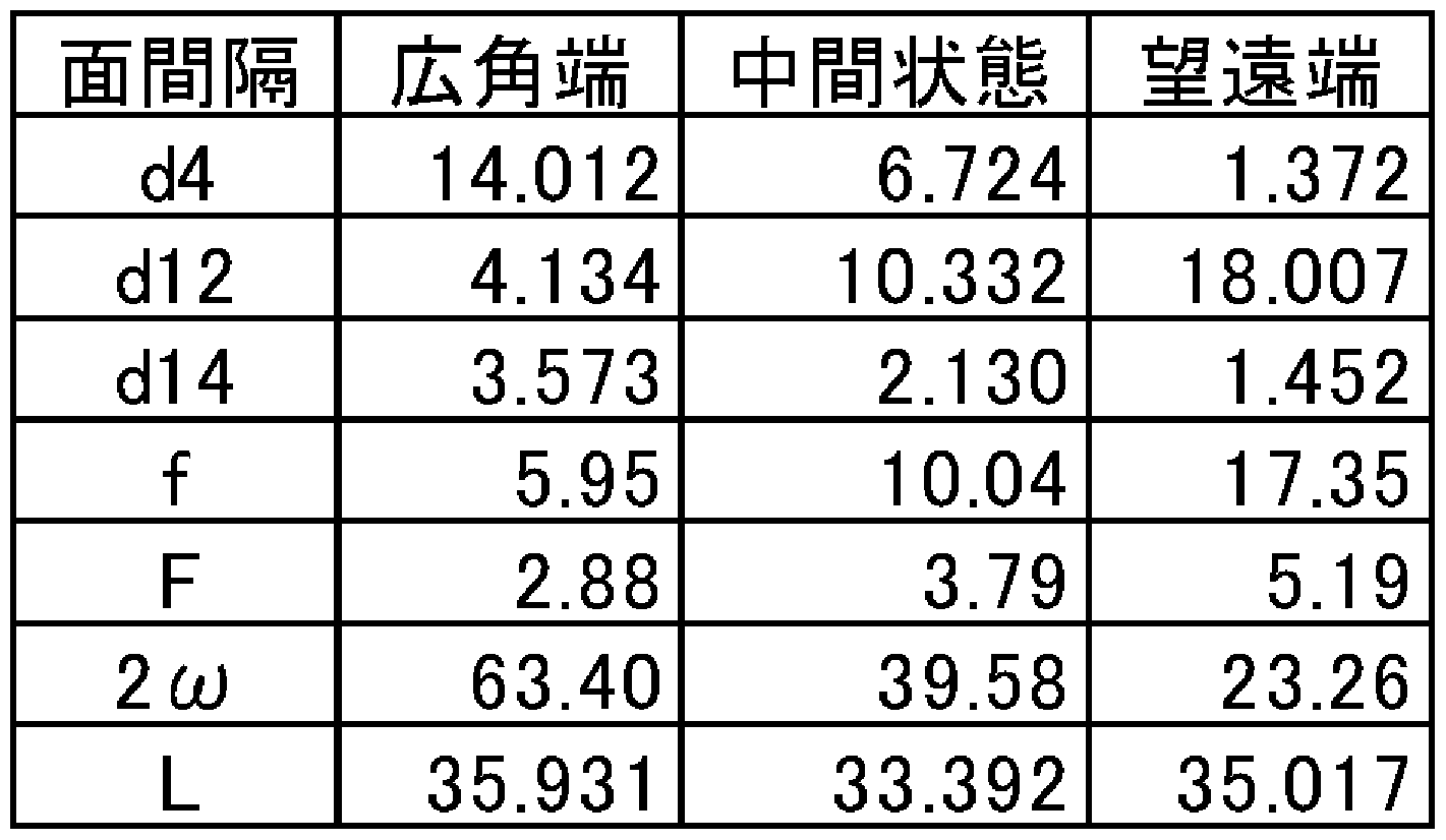
- Table 3 shows the focal length, F number, angle of view, optical total length, and variable surface distance data when the shooting distance is ⁇ . Shown in
- the zoom lens system of Example 2 corresponds to Embodiment 2 shown in FIGS. 3A and 3C.
- Table 4 shows the lens data of the zoom lens system of Example 2
- Table 5 shows the aspheric data
- the shooting distance is Table 6 shows the focal length, F number, angle of view, total optical length, and variable surface distance data for ⁇ .
- the zoom lens system of Example 3 corresponds to Embodiment 3 shown in FIGS. 5A to 5C.
- Table 7 shows the lens data of the zoom lens system of Example 3
- Table 8 shows the aspheric data
- Table 9 shows the focal length, F number, field angle, optical total length, and variable surface distance data when the shooting distance is ⁇ . Shown in
- the zoom lens system of Example 4 corresponds to Embodiment 4 shown in FIGS.
- Table 10 shows the lens data of the zoom lens system of Example 4
- Table 11 shows the aspheric data
- Table 12 shows the focal length, F number, angle of view, optical total length, and variable surface distance data when the shooting distance is ⁇ . Shown in
- the zoom lens system of Example 5 corresponds to Embodiment 5 shown in FIGS. 9A and 9C.
- Table 13 shows the lens data for the zoom lens system of Example 5
- Table 14 shows the aspheric data
- Table 15 shows the focal length, F-number, field angle, optical total length, and variable surface distance data when the shooting distance is ⁇ . Shown in
- FIGS. 2A to 2I are longitudinal aberration diagrams of the zoom lens system according to Example 1.
- FIGS. 4A to 4I are longitudinal aberration diagrams of the zoom lens system according to Example 2.
- FIG. 6A to 6I are longitudinal aberration diagrams of the zoom lens system according to Example 3.
- FIGS. 8A to 8I are longitudinal graphs of the zoom lens system according to Example 4.
- FIG. 10A to LOI are longitudinal aberration diagrams of the zoom lens system according to Example 5.
- FIGS. 2D to 2F, FIGS. 4D to 4F, FIGS. 6D to 6F, FIGS. 8D to 8F, and FIGS. 10D to 10F represent aberrations at intermediate positions.
- Figures 2G-2I, 4G-4I, 6G-6I, 8G-8I and 10G-: LOI represents the aberration at the telephoto end.
- 2A, 2D, 2G, 4A, 4D, 4G, 6A, 6D, 6G, 8A, 8D, 8G, 10A, 10D and IOG show spherical aberration.
- Figures 2B, 2E, 2H, 4B, 4E, 4H, 6B, 6E, 6H, 8B, 8E, 8H, 10B, IOE and IOH indicate astigmatism.
- 2C, 2F, 21, 4C, 4F, 41, 6C, 6F, 61, 8C, 8F, 81, IOC, IOF and 101 show distortion aberration.
- the vertical axis represents the F number
- the solid line is the d line
- the short broken line is the F line
- the long broken line is the C line characteristic.
- the vertical axis represents the half field angle
- the solid line represents the sagittal plane
- the broken line represents the meridional plane.
- the vertical axis represents the half angle of view.
- FIGS. 11A to 11F are lateral aberration diagrams at the telephoto end of the zoom lens system according to Example 1.
- FIGS. FIGS. 12A to 12F are diagrams illustrating the lateral convergence at the telephoto end of the zoom lens system according to Example 2.
- FIG. 13A to 13F are lateral aberration diagrams at the telephoto end of the zoom lens system according to Example 3.
- FIGS. 14A to 14F are lateral aberration diagrams at the telephoto end of the zoom lens system according to Example 4.
- FIGS. 15A to 15F are lateral aberration diagrams at the telephoto end of the zoom lens system according to Example 5.
- FIGS. 11A to 11C, 12A to 12C, 13A to 13C, 14-8 to 14 and 15 8 to 15 are lateral aberration diagrams corresponding to a basic state where image blur correction is not performed at the telephoto end.
- Figures 11D to 11F, 12D to 12F, 13D to 13F, 14D to 14F, and 15D to 15F show image blur correction at the telephoto end in which the entire second lens group G2 is moved by a predetermined amount in the direction perpendicular to the optical axis.
- It is a lateral aberration diagram corresponding to the state.
- FIGS. 11A, 12A, 13A, 14A and 15A correspond to lateral aberrations at an image point of 75% of the maximum image height.
- IC, 12C, 13C, 14C and 15C correspond to lateral aberrations at -75% image point of maximum image height.
- FIGS. 11D, 12D, 13D, 14D, and 15D correspond to the lateral aberration at the image point of 75% of the maximum image height.
- 11E, 12E, 13E, 14E, and 15E correspond to lateral aberrations at the axial image point.
- FIGS. 11F, 12F, 13F, 14F and 15F correspond to lateral aberrations at an image point of ⁇ 75% of the maximum image height.
- the meridional plane is defined as a plane including the optical axis of the first lens group G1 and the optical axis of the second lens group G2.
- the amount of movement of the second lens group G2 in the direction perpendicular to the optical axis in the image blur correction state is as follows: real Jif row 1 force SO. 094mm, Jfef row 2 force 0.009mm, Jfef row 3 force 0.095 mm, Jfef row 4 force ⁇ 0.094 mm, Example 5 is 0.098 mm. Note that when the shooting distance is ⁇ and the zoom lens system is tilted by 0.6 ° at the telephoto end, the entire amount of the second lens group G2 translates in the direction perpendicular to the optical axis by the above values. Equal to the amount of image eccentricity when
- the zoom lens system according to the present invention is applicable to digital input devices such as digital still cameras, digital video cameras, mobile phone devices, PDAs (Personal Digital Assistance), surveillance cameras in surveillance systems, Web cameras, and in-vehicle cameras. Particularly, it is suitable for a photographing optical system that requires high image quality, such as a digital still camera and a digital video camera.
Abstract
Description


Claims
Priority Applications (4)
| Application Number | Priority Date | Filing Date | Title |
|---|---|---|---|
| EP05753306A EP1762876A1 (en) | 2004-06-29 | 2005-06-27 | Zoom lens system, imaging device, and camera |
| JP2006528675A JP4792395B2 (en) | 2004-06-29 | 2005-06-27 | Zoom lens system, imaging device and camera |
| US11/631,003 US7369323B2 (en) | 2004-06-29 | 2005-06-27 | Zoom lens system, imaging device and camera |
| US12/073,192 US7697215B2 (en) | 2004-06-29 | 2008-03-03 | Zoom lens system, imaging device and camera |
Applications Claiming Priority (2)
| Application Number | Priority Date | Filing Date | Title |
|---|---|---|---|
| JP2004191992 | 2004-06-29 | ||
| JP2004-191992 | 2004-06-29 |
Related Child Applications (2)
| Application Number | Title | Priority Date | Filing Date |
|---|---|---|---|
| US11/631,003 A-371-Of-International US7369323B2 (en) | 2004-06-29 | 2005-06-27 | Zoom lens system, imaging device and camera |
| US12/073,192 Division US7697215B2 (en) | 2004-06-29 | 2008-03-03 | Zoom lens system, imaging device and camera |
Publications (1)
| Publication Number | Publication Date |
|---|---|
| WO2006001431A1 true WO2006001431A1 (en) | 2006-01-05 |
Family
ID=35781862
Family Applications (1)
| Application Number | Title | Priority Date | Filing Date |
|---|---|---|---|
| PCT/JP2005/011761 WO2006001431A1 (en) | 2004-06-29 | 2005-06-27 | Zoom lens system, imaging device, and camera |
Country Status (5)
| Country | Link |
|---|---|
| US (2) | US7369323B2 (en) |
| EP (1) | EP1762876A1 (en) |
| JP (1) | JP4792395B2 (en) |
| CN (2) | CN101539660B (en) |
| WO (1) | WO2006001431A1 (en) |
Cited By (3)
| Publication number | Priority date | Publication date | Assignee | Title |
|---|---|---|---|---|
| JP2007333799A (en) * | 2006-06-12 | 2007-12-27 | Nikon Corp | Zoom lens and optical device having the same |
| US7612949B2 (en) | 2006-12-27 | 2009-11-03 | Sony Corporation | Zoom lens and imaging apparatus |
| JP2012088735A (en) * | 2011-12-28 | 2012-05-10 | Canon Inc | Zoom lens and imaging apparatus including the same |
Families Citing this family (11)
| Publication number | Priority date | Publication date | Assignee | Title |
|---|---|---|---|---|
| JP4792395B2 (en) * | 2004-06-29 | 2011-10-12 | パナソニック株式会社 | Zoom lens system, imaging device and camera |
| US7471453B2 (en) * | 2005-11-17 | 2008-12-30 | Panasonic Corporation | Zoom lens system, imaging device and camera |
| JP4928288B2 (en) * | 2007-01-30 | 2012-05-09 | キヤノン株式会社 | Zoom lens and imaging apparatus having the same |
| US7755847B2 (en) | 2007-05-29 | 2010-07-13 | Panasonic Corporation | Zoom lens system, imaging device and camera |
| US7593166B2 (en) * | 2007-05-29 | 2009-09-22 | Panasonic Corporation | Zoom lens system, imaging device and camera |
| JP5309553B2 (en) * | 2007-12-25 | 2013-10-09 | 株式会社ニコン | Zoom lens and optical apparatus provided with the zoom lens |
| JP5349938B2 (en) * | 2008-12-11 | 2013-11-20 | キヤノン株式会社 | Zoom lens |
| JP2010256417A (en) * | 2009-04-21 | 2010-11-11 | Sony Corp | Zoom lens and imaging apparatus |
| US8749892B2 (en) | 2011-06-17 | 2014-06-10 | DigitalOptics Corporation Europe Limited | Auto-focus actuator for field curvature correction of zoom lenses |
| CN107076968A (en) * | 2014-07-30 | 2017-08-18 | 株式会社尼康 | The manufacture method of variable-power optical system, Optical devices and variable-power optical system |
| CN114185161B (en) * | 2021-12-13 | 2023-09-05 | 江西晶超光学有限公司 | Optical system, lens module and electronic equipment |
Citations (23)
| Publication number | Priority date | Publication date | Assignee | Title |
|---|---|---|---|---|
| JP2001281545A (en) * | 1999-10-06 | 2001-10-10 | Canon Inc | Zoom lens and optical equipment using the same |
| JP2001296476A (en) * | 2000-04-14 | 2001-10-26 | Canon Inc | Zoom lens and optical equipment using the same |
| JP2001296475A (en) * | 2000-04-14 | 2001-10-26 | Canon Inc | Zoom lens and optical equipment using the same |
| JP2002048975A (en) * | 2000-05-23 | 2002-02-15 | Olympus Optical Co Ltd | Electronic image pickup device |
| JP2002244043A (en) * | 2001-02-22 | 2002-08-28 | Canon Inc | Zoom lens and optical instrument using it |
| JP2003057547A (en) * | 2001-08-14 | 2003-02-26 | Canon Inc | Zoom lens and optical equipment having the same |
| JP2003114386A (en) * | 2001-10-04 | 2003-04-18 | Olympus Optical Co Ltd | Electronic imaging device |
| JP2003121743A (en) * | 2001-10-18 | 2003-04-23 | Olympus Optical Co Ltd | Zoom lens and electronic image pickup device using the same |
| JP2003121740A (en) * | 2001-10-11 | 2003-04-23 | Olympus Optical Co Ltd | Electronic imaging device |
| JP2003121741A (en) * | 2001-10-11 | 2003-04-23 | Olympus Optical Co Ltd | Electronic imaging device |
| JP2003131132A (en) * | 2001-10-22 | 2003-05-08 | Olympus Optical Co Ltd | Electronic imaging unit |
| JP2003140043A (en) * | 2001-11-07 | 2003-05-14 | Olympus Optical Co Ltd | Zoom lens and electronic image pickup device using the same |
| JP2003149553A (en) * | 2001-11-09 | 2003-05-21 | Canon Inc | Zoom lens and optical equipment having the same |
| JP2003149556A (en) * | 2001-11-16 | 2003-05-21 | Olympus Optical Co Ltd | Zoom lens and electronic image pickup device using the same |
| JP2003177316A (en) * | 2001-12-11 | 2003-06-27 | Olympus Optical Co Ltd | Image pickup device |
| JP2004102211A (en) * | 2001-11-26 | 2004-04-02 | Olympus Corp | Zoom lens and electronic imaging apparatus using same |
| JP2004170664A (en) * | 2002-11-20 | 2004-06-17 | Olympus Corp | Imaging lens system, and imaging device using the same |
| JP2004246141A (en) * | 2003-02-14 | 2004-09-02 | Olympus Corp | Electronic imaging unit |
| JP2004318105A (en) * | 2003-03-31 | 2004-11-11 | Konica Minolta Photo Imaging Inc | Zoom lens device |
| JP2004333767A (en) * | 2003-05-06 | 2004-11-25 | Canon Inc | Zoom lens and optical equipment having the same |
| JP2005099091A (en) * | 2003-09-22 | 2005-04-14 | Olympus Corp | Zoom lens and electronic imaging apparatus using the same |
| JP2005164653A (en) * | 2003-11-28 | 2005-06-23 | Kyocera Corp | Imaging device |
| JP2005234460A (en) * | 2004-02-23 | 2005-09-02 | Canon Inc | Zoom lens and imaging apparatus provided with the same |
Family Cites Families (23)
| Publication number | Priority date | Publication date | Assignee | Title |
|---|---|---|---|---|
| US6308011B1 (en) * | 1998-03-31 | 2001-10-23 | Canon Kabushiki Kaisha | Zoom lens and photographic apparatus having the same |
| US6545819B1 (en) | 1999-08-31 | 2003-04-08 | Canon Kabushiki Kaisha | Zoom lens and optical apparatus having the same |
| JP3710352B2 (en) | 2000-03-27 | 2005-10-26 | キヤノン株式会社 | Zoom lens and optical apparatus using the same |
| US6498687B1 (en) | 1999-10-06 | 2002-12-24 | Canon Kabushiki Kaisha | Zoom lens and optical apparatus having the same |
| JP4483086B2 (en) | 2000-12-25 | 2010-06-16 | コニカミノルタホールディングス株式会社 | Zoom lens |
| EP1220002B1 (en) | 2000-12-27 | 2006-09-20 | Canon Kabushiki Kaisha | Zoom lens |
| US6828218B2 (en) | 2001-05-31 | 2004-12-07 | Samsung Electronics Co., Ltd. | Method of forming a thin film using atomic layer deposition |
| US6664358B2 (en) | 2001-06-28 | 2003-12-16 | Nova Chemicals (International) S.A. | Highly alternating ethylene styrene interpolymers |
| JP2003036650A (en) * | 2001-07-23 | 2003-02-07 | Sony Corp | Disk recording and reproducing apparatus |
| JP2003159553A (en) | 2001-09-17 | 2003-06-03 | Tokyo Electron Ltd | Coated film formation device |
| JP2003140047A (en) | 2001-10-30 | 2003-05-14 | Canon Inc | Zoom lens and optical equipment with the same |
| JP2003128261A (en) * | 2001-10-30 | 2003-05-08 | Heishin Engineering & Equipment Co Ltd | Feeder for dewatering cake provided with uniaxial eccentric screw pump |
| US7002755B2 (en) | 2001-11-26 | 2006-02-21 | Olympus Corporation | Zoom lens, and electronic imaging system using the same |
| JP4138671B2 (en) | 2002-04-11 | 2008-08-27 | 松下電器産業株式会社 | Zoom lens and electronic still camera using the same |
| JP2003329512A (en) * | 2002-05-10 | 2003-11-19 | Koyo Seiko Co Ltd | Apparatus and method for measurement of natural oscillation frequency of roller bearing |
| US20040007641A1 (en) | 2002-07-10 | 2004-01-15 | Dickie Robert G. | Hose reeler with sprinkler head |
| JP3830867B2 (en) * | 2002-07-10 | 2006-10-11 | Necエレクトロニクス株式会社 | Single-chip microcomputer and its boot area switching method |
| JP2004083260A (en) * | 2002-08-28 | 2004-03-18 | Akira Sugimoto | Life assistive instrument moving device |
| US7075732B2 (en) | 2003-09-22 | 2006-07-11 | Olympus Corporation | Zoom optical system, and imaging system incorporating the same |
| US7092170B2 (en) * | 2004-04-30 | 2006-08-15 | Olympus Corporation | Zoom lens and image pickup apparatus |
| JP4792395B2 (en) * | 2004-06-29 | 2011-10-12 | パナソニック株式会社 | Zoom lens system, imaging device and camera |
| JP4612823B2 (en) * | 2004-09-16 | 2011-01-12 | キヤノン株式会社 | Zoom lens and imaging apparatus having the same |
| JP4914136B2 (en) * | 2005-09-06 | 2012-04-11 | キヤノン株式会社 | Zoom lens and imaging apparatus having the same |
-
2005
- 2005-06-27 JP JP2006528675A patent/JP4792395B2/en not_active Expired - Fee Related
- 2005-06-27 WO PCT/JP2005/011761 patent/WO2006001431A1/en not_active Application Discontinuation
- 2005-06-27 EP EP05753306A patent/EP1762876A1/en not_active Withdrawn
- 2005-06-27 US US11/631,003 patent/US7369323B2/en not_active Expired - Fee Related
- 2005-06-27 CN CN2009101385176A patent/CN101539660B/en not_active Expired - Fee Related
- 2005-06-27 CN CNA2005800218848A patent/CN1977205A/en active Pending
-
2008
- 2008-03-03 US US12/073,192 patent/US7697215B2/en not_active Expired - Fee Related
Patent Citations (23)
| Publication number | Priority date | Publication date | Assignee | Title |
|---|---|---|---|---|
| JP2001281545A (en) * | 1999-10-06 | 2001-10-10 | Canon Inc | Zoom lens and optical equipment using the same |
| JP2001296476A (en) * | 2000-04-14 | 2001-10-26 | Canon Inc | Zoom lens and optical equipment using the same |
| JP2001296475A (en) * | 2000-04-14 | 2001-10-26 | Canon Inc | Zoom lens and optical equipment using the same |
| JP2002048975A (en) * | 2000-05-23 | 2002-02-15 | Olympus Optical Co Ltd | Electronic image pickup device |
| JP2002244043A (en) * | 2001-02-22 | 2002-08-28 | Canon Inc | Zoom lens and optical instrument using it |
| JP2003057547A (en) * | 2001-08-14 | 2003-02-26 | Canon Inc | Zoom lens and optical equipment having the same |
| JP2003114386A (en) * | 2001-10-04 | 2003-04-18 | Olympus Optical Co Ltd | Electronic imaging device |
| JP2003121740A (en) * | 2001-10-11 | 2003-04-23 | Olympus Optical Co Ltd | Electronic imaging device |
| JP2003121741A (en) * | 2001-10-11 | 2003-04-23 | Olympus Optical Co Ltd | Electronic imaging device |
| JP2003121743A (en) * | 2001-10-18 | 2003-04-23 | Olympus Optical Co Ltd | Zoom lens and electronic image pickup device using the same |
| JP2003131132A (en) * | 2001-10-22 | 2003-05-08 | Olympus Optical Co Ltd | Electronic imaging unit |
| JP2003140043A (en) * | 2001-11-07 | 2003-05-14 | Olympus Optical Co Ltd | Zoom lens and electronic image pickup device using the same |
| JP2003149553A (en) * | 2001-11-09 | 2003-05-21 | Canon Inc | Zoom lens and optical equipment having the same |
| JP2003149556A (en) * | 2001-11-16 | 2003-05-21 | Olympus Optical Co Ltd | Zoom lens and electronic image pickup device using the same |
| JP2004102211A (en) * | 2001-11-26 | 2004-04-02 | Olympus Corp | Zoom lens and electronic imaging apparatus using same |
| JP2003177316A (en) * | 2001-12-11 | 2003-06-27 | Olympus Optical Co Ltd | Image pickup device |
| JP2004170664A (en) * | 2002-11-20 | 2004-06-17 | Olympus Corp | Imaging lens system, and imaging device using the same |
| JP2004246141A (en) * | 2003-02-14 | 2004-09-02 | Olympus Corp | Electronic imaging unit |
| JP2004318105A (en) * | 2003-03-31 | 2004-11-11 | Konica Minolta Photo Imaging Inc | Zoom lens device |
| JP2004333767A (en) * | 2003-05-06 | 2004-11-25 | Canon Inc | Zoom lens and optical equipment having the same |
| JP2005099091A (en) * | 2003-09-22 | 2005-04-14 | Olympus Corp | Zoom lens and electronic imaging apparatus using the same |
| JP2005164653A (en) * | 2003-11-28 | 2005-06-23 | Kyocera Corp | Imaging device |
| JP2005234460A (en) * | 2004-02-23 | 2005-09-02 | Canon Inc | Zoom lens and imaging apparatus provided with the same |
Cited By (3)
| Publication number | Priority date | Publication date | Assignee | Title |
|---|---|---|---|---|
| JP2007333799A (en) * | 2006-06-12 | 2007-12-27 | Nikon Corp | Zoom lens and optical device having the same |
| US7612949B2 (en) | 2006-12-27 | 2009-11-03 | Sony Corporation | Zoom lens and imaging apparatus |
| JP2012088735A (en) * | 2011-12-28 | 2012-05-10 | Canon Inc | Zoom lens and imaging apparatus including the same |
Also Published As
| Publication number | Publication date |
|---|---|
| US20070285801A1 (en) | 2007-12-13 |
| CN101539660B (en) | 2013-07-03 |
| CN101539660A (en) | 2009-09-23 |
| US7697215B2 (en) | 2010-04-13 |
| JP4792395B2 (en) | 2011-10-12 |
| EP1762876A1 (en) | 2007-03-14 |
| JPWO2006001431A1 (en) | 2008-04-17 |
| US20080158691A1 (en) | 2008-07-03 |
| CN1977205A (en) | 2007-06-06 |
| US7369323B2 (en) | 2008-05-06 |
Similar Documents
| Publication | Publication Date | Title |
|---|---|---|
| JP4792395B2 (en) | Zoom lens system, imaging device and camera | |
| JP4138671B2 (en) | Zoom lens and electronic still camera using the same | |
| JP5049012B2 (en) | Zoom lens system, imaging device and camera | |
| JP5429612B2 (en) | Zoom lens, information device, and imaging device | |
| US7782543B2 (en) | Zoom lens and image pickup apparatus having the same | |
| CN114063268B (en) | Image capturing lens system, image capturing device and electronic device | |
| WO2006090660A1 (en) | Zoom lens system, imaging apparatus and camera | |
| US8477428B2 (en) | Zoom lens and image pickup apparatus having the zoom lens | |
| US8045274B2 (en) | Zoom lens and image pickup apparatus using the same | |
| KR101890304B1 (en) | Zoom lens and photographing apparatus | |
| WO2004111698A1 (en) | Zoom lens, imaging device, and camera having imaging device | |
| JP4917922B2 (en) | Zoom lens system, imaging device and camera | |
| WO2009044664A1 (en) | Zoom lens and image capturing apparatus having the same | |
| JP4758151B2 (en) | Zoom lens system, imaging device and camera | |
| JP2008039838A (en) | Zoom lens system, image pickup apparatus, and camera | |
| JP2007212636A (en) | Zoom lens system, imaging apparatus and camera | |
| JP5049021B2 (en) | Zoom lens system, imaging device and camera | |
| JP5042643B2 (en) | Zoom lens system, imaging device and camera | |
| KR101507808B1 (en) | Zoom lens and imaging optical device having the same | |
| JP4172197B2 (en) | Zoom lens and electronic still camera | |
| JP4870527B2 (en) | Zoom lens system, imaging device and camera | |
| JP4960713B2 (en) | Zoom lens system, imaging device and camera | |
| JP4271436B2 (en) | Zoom lens and electronic still camera | |
| JP4913634B2 (en) | Zoom lens system, imaging device and camera | |
| JP2006113111A (en) | Zoom lens system, imaging apparatus and camera |
Legal Events
| Date | Code | Title | Description |
|---|---|---|---|
| AK | Designated states |
Kind code of ref document: A1 Designated state(s): AE AG AL AM AT AU AZ BA BB BG BR BW BY BZ CA CH CN CO CR CU CZ DE DK DM DZ EC EE EG ES FI GB GD GE GH GM HR HU ID IL IN IS JP KE KG KM KP KR KZ LC LK LR LS LT LU LV MA MD MG MK MN MW MX MZ NA NG NI NO NZ OM PG PH PL PT RO RU SC SD SE SG SK SL SM SY TJ TM TN TR TT TZ UA UG US UZ VC VN YU ZA ZM ZW |
|
| AL | Designated countries for regional patents |
Kind code of ref document: A1 Designated state(s): GM KE LS MW MZ NA SD SL SZ TZ UG ZM ZW AM AZ BY KG KZ MD RU TJ TM AT BE BG CH CY CZ DE DK EE ES FI FR GB GR HU IE IS IT LT LU MC NL PL PT RO SE SI SK TR BF BJ CF CG CI CM GA GN GQ GW ML MR NE SN TD TG |
|
| 121 | Ep: the epo has been informed by wipo that ep was designated in this application | ||
| WWE | Wipo information: entry into national phase |
Ref document number: 2006528675 Country of ref document: JP |
|
| WWE | Wipo information: entry into national phase |
Ref document number: 2005753306 Country of ref document: EP |
|
| WWE | Wipo information: entry into national phase |
Ref document number: 11631003 Country of ref document: US |
|
| WWE | Wipo information: entry into national phase |
Ref document number: 200580021884.8 Country of ref document: CN |
|
| NENP | Non-entry into the national phase |
Ref country code: DE |
|
| WWW | Wipo information: withdrawn in national office |
Country of ref document: DE |
|
| WWP | Wipo information: published in national office |
Ref document number: 2005753306 Country of ref document: EP |
|
| WWW | Wipo information: withdrawn in national office |
Ref document number: 2005753306 Country of ref document: EP |
|
| WWP | Wipo information: published in national office |
Ref document number: 11631003 Country of ref document: US |