JP2007333601A - Fuel inspection system - Google Patents
Fuel inspection system Download PDFInfo
- Publication number
- JP2007333601A JP2007333601A JP2006166676A JP2006166676A JP2007333601A JP 2007333601 A JP2007333601 A JP 2007333601A JP 2006166676 A JP2006166676 A JP 2006166676A JP 2006166676 A JP2006166676 A JP 2006166676A JP 2007333601 A JP2007333601 A JP 2007333601A
- Authority
- JP
- Japan
- Prior art keywords
- fuel
- inspection apparatus
- fiberscope
- main body
- installation base
- Prior art date
- Legal status (The legal status is an assumption and is not a legal conclusion. Google has not performed a legal analysis and makes no representation as to the accuracy of the status listed.)
- Pending
Links
Images


Classifications
-
- Y—GENERAL TAGGING OF NEW TECHNOLOGICAL DEVELOPMENTS; GENERAL TAGGING OF CROSS-SECTIONAL TECHNOLOGIES SPANNING OVER SEVERAL SECTIONS OF THE IPC; TECHNICAL SUBJECTS COVERED BY FORMER USPC CROSS-REFERENCE ART COLLECTIONS [XRACs] AND DIGESTS
- Y02—TECHNOLOGIES OR APPLICATIONS FOR MITIGATION OR ADAPTATION AGAINST CLIMATE CHANGE
- Y02E—REDUCTION OF GREENHOUSE GAS [GHG] EMISSIONS, RELATED TO ENERGY GENERATION, TRANSMISSION OR DISTRIBUTION
- Y02E30/00—Energy generation of nuclear origin
- Y02E30/30—Nuclear fission reactors
Abstract
Description
本発明は燃料検査装置に関し、特に放射能の漏洩が生じた燃料棒を特定し、破損した燃料棒の表面やその周辺部位の観察を行なうことができる燃料検査装置に関する。 The present invention relates to a fuel inspection apparatus, and more particularly to a fuel inspection apparatus that can identify a fuel rod in which leakage of radioactivity has occurred and observe the surface of the damaged fuel rod and its surrounding area.
原子炉の運転中に放射能の漏洩が認められたときには、原子炉の運転サイクルの終了後に、(1)漏洩をおこした、即ち破損した燃料棒が組み込まれた燃料集合体を特定し、(2)当該燃料集合体中の破損した(燃料棒の「破損」の結果「放射能の漏洩」が生じるため、燃料棒には原則として「破損」を使用する)燃料棒を特定し、(3)当該燃料棒の破損箇所を特定し、破損箇所やその周辺部位を観察して破損の原因を究明することが行なわれている。 When radioactivity leakage is observed during the operation of the reactor, after the end of the reactor operation cycle, (1) identify the fuel assembly that has leaked, that is, the broken fuel rods are incorporated, ( 2) Identify the fuel rod in the fuel assembly that is broken (use “damage” as a rule for fuel rods as a result of “braking” of the fuel rods, resulting in “radioactive leakage”), and (3 ) The location of the fuel rod is identified, and the cause of the damage is investigated by observing the damaged location and its surroundings.
漏洩をおこしている燃料集合体の特定は、各燃料集合体を他の燃料集合体から隔離して個々に放射能を放出しているか否かを調べるシッピング検査によりなされる。(非特許文献1)破損を起こした燃料棒の特定は、放射能を漏洩していると特定された燃料集合体の各燃料棒を超音波(UT)検査することによりなされる。破損箇所の特定や当該箇所の観察等は、ファイバースコープを使用した検査によりなされる。 The leaking fuel assembly is identified by a shipping inspection in which each fuel assembly is isolated from the other fuel assemblies and it is individually examined whether or not radioactivity is released. (Non-Patent Document 1) The identification of the fuel rod that has caused the damage is performed by ultrasonic (UT) inspection of each fuel rod of the fuel assembly that is identified as leaking radioactivity. The identification of the damaged part and the observation of the part are made by inspection using a fiberscope.
シッピング検査装置は、使用済み燃料用プール(以下、原則として「プール」と記す)に常設されているが、超音波検査装置とファイバースコープ検査装置(以下、特に区別する必要がないときには、これらの検査装置をあわせて、「検査装置」とも記す)は常設ではなく、検査の必要性が発生したときにプール内に沈めこまれ、セッティング(燃料集合体に対して、種々の検査を行なうことが可能なように設置すること)がなされる。なお、シッピング検査は、本発明に直接の関係がないため、説明を省略する。 The shipping inspection device is permanently installed in the spent fuel pool (hereinafter referred to as “pool” in principle), but the ultrasonic inspection device and the fiberscope inspection device (hereinafter, when there is no need to distinguish between them) The inspection device (also referred to as “inspection device”) is not permanent, and it is submerged in the pool when a need for inspection occurs, and settings (a variety of inspections can be performed on the fuel assembly) To be installed as possible). Note that the shipping inspection is not directly related to the present invention, and thus the description thereof is omitted.
図5を参照しつつ、超音波を使用して破損した燃料棒を特定する方法について説明する。図5は、破損した燃料棒を超音波を使用して検出(特定)する様子を示す図である。図5において、131は超音波検査装置の発信子側のプローブであり、132は受信子側のプローブである。310は健全な燃料棒であり、他の健全な燃料棒を○で示す。311は、破損した燃料棒であり、×印でこれを示す。
燃料集合体には、燃料棒が例えば17×17の行列状に配列して組み込まれているが、図5の上の図に示す様に、燃料棒が17本並んだ(図5には、その一部を示す)1つの列の一方側(図面では上側)に超音波検査装置の発信子側のプローブ131を水平に配置し、他方の側(図面では下側)の対向する位置に受信子側のプローブ132を配置し、両方のプローブ131、132をペアで検査対象の燃料棒の列の一端から多端に、即ち列に沿って(図面では、左から右に)矢印の方向に移動させて行き、各燃料棒の位置毎に受信強度を調べる。
With reference to FIG. 5, a method of identifying a broken fuel rod using ultrasonic waves will be described. FIG. 5 is a diagram showing a state where a broken fuel rod is detected (specified) using ultrasonic waves. In FIG. 5, 131 is a probe on the transmitter side of the ultrasonic inspection apparatus, and 132 is a probe on the receiver side. 310 is a healthy fuel rod, and other healthy fuel rods are indicated by circles.
The fuel assembly is assembled with fuel rods arranged in a 17 × 17 matrix, for example. As shown in the upper diagram of FIG. 5, 17 fuel rods are arranged (FIG. The
燃料棒310が健全であれば、ジルカロイ合金製の被覆管の内面は気体(ヘリウム)に接触しているため超音波の界面での反射により超音波の伝導性が良好であり、超音波検査装置の発信子側のプローブ131と受信子側のプローブ132とのペアが燃料棒310を通過する際、図5の下の図の○印を付した例に示す様に、2つの受信のピークが生じる。
破損した燃料棒311は、内部に冷却水が浸入しているため、被覆管の界面での超音波の反射がうまくなされず、超音波の伝導性が悪化する。このため、図5の下の図の○の中に×を入れた印を付した例に示す様にピークの強度が弱くなり、これにより破損していることが判る。
これを、全ての燃料棒の列について行なうことにより、破損した燃料棒が特定される。
If the
Since the
By doing this for all rows of fuel rods, the broken fuel rods are identified.
破損していると特定された燃料棒311の破損箇所の特定、破損箇所やその周辺部位のファイバースコープによる観察の様子を、図6を参照しつつ説明する。図6は、ファイバースコープでグリッド内を観察している様子を示す図である。図6において、111はファイバースコープ(ファイバースコープヘッド)であり、320は燃料集合体の支持グリッドであり、321はその横方向の格子板であり、322は縦方向の格子板であり、323はそのディンプル部(ハードストップとソフトストップ)である。
ファイバースコープ111は、上方斜視、下方斜視、側方視を同時に行なうことが可能であるようにグラスファイバーが取付けられている。ファイバースコープ111を、検査対象の破損した燃料棒311の隣接する燃料棒と間にあるスペース、かつ破損した燃料棒311の近くに差し込み、上下に隣接する支持グリッド間毎に(スパン毎)に観察を行なう。ここに、上方斜視、下方斜視を行なうのは、支持グリッド320の内側で燃料棒311を弾性支持しつつ拘束しているディンプル部323で燃料棒の破損が生じることが多いため、ディンプル部323の上方や下方から当該箇所を観察可能とするためである。
With reference to FIG. 6, description will be given of how the
The
燃料集合体の水平断面の1方向、例えば図6の上図の左側からの観察が終了すると、一旦ファイバースコープ111を燃料集合体から引抜き、燃料集合体を90度回転させて、再度燃料集合体の異なる方向、例えば図6の上図の上側から観察する。
1スパン分の観察が終了すると、一旦ファイバースコープ111を燃料集合体から引抜き、燃料集合体を使用済み燃料プール内で1スパン分だけ上方あるいは下方に動かし、再度ファイバースコープ111を差込み、次のスパンについても同じ様に観察する。
この様な作業を繰返して、破損が生じた各燃料棒の上下方向、4周からの観察を行ない、破損箇所やその周辺部位の観察等が行なわれる。
When the observation for one span is completed, the
By repeating such an operation, the broken fuel rods are observed from the upper and lower sides and four rounds, and the damaged part and its surrounding parts are observed.
しかしながら、検査の必要性が発生したときに超音波検査装置とファイバースコープ検査装置をプール内に沈めこみ、プール底の使用済み燃料ラックに格納されている燃料集合体に対応して、正しくセッティングする作業は、プールの上から見ながら行なう操作であり、原子力機器であるだけに慎重に行う必要があり、時間がかかる。 However, when the need for inspection occurs, the ultrasonic inspection device and the fiberscope inspection device are submerged in the pool and set correctly according to the fuel assembly stored in the spent fuel rack at the bottom of the pool. The work is an operation that is performed while looking from the top of the pool, and it is necessary to perform it carefully because it is a nuclear device, and it takes time.
さらに、セッティングにはクレーンが必用であるが、原子炉の停止時に一度になされる他の多くの作業にもクレーンが必要であり、クレーンの使用に際してこれら他の作業との時間的な調整が必要となり、ますます時間がかかる。
このため、放射能の漏洩が発生した燃料集合体や燃料棒を検査する際、超音波検査装置とファイバースコープ検査装置の使用済み燃料プール内への沈め込みと、燃料集合体に対応したセッティングに要する時間を少なくして検査効率を向上させた技術の開発が望まれていた。
In addition, a crane is necessary for setting, but a crane is also necessary for many other operations performed at one time when the reactor is shut down, and time adjustment with these other operations is necessary when using the crane. It will take more time.
For this reason, when inspecting a fuel assembly or fuel rod that has leaked radioactivity, the ultrasonic inspection device and the fiberscope inspection device are submerged into the spent fuel pool and the setting corresponding to the fuel assembly is used. There has been a demand for development of a technique that improves inspection efficiency by reducing the time required.
本発明は、以上の課題を解決することを目的としてなされたものであり、超音波検査装置とファイバースコープ検査装置を一体化させたものである。以下、各請求項の発明を説明する。 The present invention has been made for the purpose of solving the above problems, and is an integration of an ultrasonic inspection apparatus and a fiberscope inspection apparatus. Hereinafter, the invention of each claim will be described.
請求項1に記載の発明は、
超音波検査装置とファイバースコープ検査装置を一体的に備えていることを特徴とする燃料検査装置である。
The invention described in claim 1
A fuel inspection device comprising an ultrasonic inspection device and a fiberscope inspection device integrally.
本請求項の発明の燃料検査装置は、超音波検査装置とファイバースコープ検査装置を一体的に備えているため、放射能の漏洩が発生した燃料集合体の破損が生じた燃料棒の特定、特定された燃料棒の破損箇所やその周辺部位を観察するために超音波検査装置とファイバースコープ検査装置を同時に沈めこみ、燃料集合体に対応したセッティングがなされる。このため、それらに要する時間が従来に比べて大幅に短縮される結果、検査効率が大きく向上する。
またこのため、他の作業とクレーンの使用について行なう調節等も容易となる。
ここに、「一体的に備えている」とは、検査に使用する際に超音波検査装置とファイバースコープ検査装置が物理的、機械的に1個の装置となっているだけでなく、いずれか一方を燃料集合体に正しくセッティングすれば、他方も自動的に正しくセッティングされることを指す。
Since the fuel inspection device of the present invention is integrally provided with an ultrasonic inspection device and a fiberscope inspection device, it is possible to identify and specify the fuel rod in which the fuel assembly that has caused the leakage of radioactivity has been damaged. The ultrasonic inspection device and the fiberscope inspection device are submerged at the same time in order to observe the damaged portion of the fuel rod and the surrounding portion, and the setting corresponding to the fuel assembly is made. For this reason, the time required for them is greatly shortened as compared with the prior art, and the inspection efficiency is greatly improved.
This also facilitates adjustments for other operations and crane use.
Here, “integrated” means not only that the ultrasonic inspection device and the fiberscope inspection device are physically and mechanically one device when used for inspection, but also any one of them. If one is correctly set in the fuel assembly, the other is automatically set correctly.
請求項2に記載の発明は、前記の燃料検査装置であって、
前記超音波検査装置とファイバースコープ検査装置は、上下方向に並んで備えられていることを特徴とする燃料検査装置である。
The invention according to claim 2 is the fuel inspection device, wherein
The ultrasonic inspection apparatus and the fiberscope inspection apparatus are provided side by side in the vertical direction.
本請求項の発明の燃料検査装置は、ファイバースコープ検査装置と超音波検査装置が上下方向に並んで備えられているため、検査装置全体の幅が狭くなり、ひいては検査装置を横方向に移動させるためのスペースが少なくて済む。
さらに、例えば17×17の行列状に配列された燃料棒の各行、各列を検査するため、超音波検査装置とファイバースコープ検査装置のいずれも燃料棒の行、列のピッチで横移動させる必要があるが、上下方向に並んでおれば、横移動の開始点と終点が同じとなるため、操作も容易となる。
In the fuel inspection apparatus according to the present invention, since the fiberscope inspection apparatus and the ultrasonic inspection apparatus are arranged side by side in the vertical direction, the width of the entire inspection apparatus is narrowed, and consequently the inspection apparatus is moved in the lateral direction. Less space for it.
Further, for example, in order to inspect each row and each column of the fuel rods arranged in a 17 × 17 matrix, both the ultrasonic inspection device and the fiberscope inspection device need to be moved laterally at the fuel rod row and column pitches. However, if they are arranged in the vertical direction, the start point and end point of the horizontal movement are the same, and the operation becomes easy.
請求項3に記載の発明は、前記の燃料検査装置であって、
前記超音波検査装置の上方にファイバースコープ検査装置が備えられていることを特徴とする燃料検査装置である。
Invention of Claim 3 is the said fuel inspection apparatus, Comprising:
A fuel inspection device is provided with a fiberscope inspection device above the ultrasonic inspection device.
本請求項の発明の燃料検査装置は、支持グリッドの内部を上下から観察するため細かい操作を行なうことが多いファイバースコープ検査装置が超音波検査装置の上方にあるため、プールの上から作業者が目視しつつ操作することが可能となる。また、ファイバースコープ検査装置は上方に位置するため、照明の影になることがなく、さらに検査のための水中ランプの設置等も容易となり、燃料棒の破損箇所やその周辺部における肉眼による観察が容易となる。この一方、超音波検査装置は、検査に照明を必要としないため、大きな不都合が生じない。
また、一体化された検査装置全体の横移動量も少なくて済む。
In the fuel inspection apparatus according to the present invention, the fiberscope inspection apparatus, which is often finely operated to observe the inside of the support grid from above and below, is located above the ultrasonic inspection apparatus. It becomes possible to operate while visually observing. In addition, since the fiberscope inspection device is located above, there is no shadow of illumination, and it is easy to install an underwater lamp for inspection, etc. It becomes easy. On the other hand, since the ultrasonic inspection apparatus does not require illumination for inspection, no major inconvenience occurs.
Further, the amount of lateral movement of the entire integrated inspection apparatus can be reduced.
請求項4に記載の発明は、前記の燃料検査装置であって、
前記超音波検査装置とファイバースコープ検査装置は、各々の検出端を燃料集合体内へ差し込み、燃料集合体から引抜く駆動装置は共通しており、何れの検査装置を駆動させるかの切替え装置を有していることを特徴とする燃料検査装置である。
Invention of Claim 4 is the said fuel inspection apparatus, Comprising:
The ultrasonic inspection apparatus and the fiberscope inspection apparatus have a common drive device for inserting each detection end into the fuel assembly and withdrawing it from the fuel assembly, and has a switching device for selecting which inspection device to drive. This is a fuel inspection device.
本請求項の発明の燃料検査装置は、ファイバースコープ検査装置と超音波検査装置の検出端を燃料集合体内へ差し込み、燃料集合体から引抜くための水中モータ(部)やエヤーシリンダー等の駆動装置が共通しているため、検査装置全体が軽量化され、コストも安くなる。
なお、ファイバースコープ検査装置と超音波検査装置の何れを駆動するかは、クラッチを有する切り替え機構等をプールの上から遠隔操作することにより調節がなされる。
The fuel inspection device according to the present invention is a drive device such as a submersible motor (part) or an air cylinder for inserting the detection end of the fiberscope inspection device and the ultrasonic inspection device into the fuel assembly and withdrawing from the fuel assembly. Therefore, the entire inspection apparatus is reduced in weight and costs are reduced.
Note that which of the fiberscope inspection apparatus and the ultrasonic inspection apparatus is driven is adjusted by remotely operating a switching mechanism having a clutch or the like from the pool.
請求項5に記載の発明は、前記の燃料検査装置であって、
前記超音波検査装置は、第1本体部と第1設置台と第1駆動部を有し、
前記第1本体部は、燃料集合体内に挿入される検出端を保持し、
前記第1設置台は、前記第1本体部を燃料集合体側の方向および反対側の方向に移動させる第1移動機構と、移動時に前記第1本体部の姿勢を保持させつつ支持する第1支持機構とを有し、
前記第1駆動部は、前記第1設置台に固定されており、前記第1移動機構を稼動させるものであり、
前記ファイバースコープ検査装置は、第2本体部と第2設置台と第2駆動部を有し、
前記第2本体部は、燃料集合体内に挿入されるファイバースコープを保持し、
前記第2設置台は、前記第2本体部を燃料集合体側の方向および反対側の方向に移動させる第2移動機構と、移動時に前記第2本体部の姿勢を保持させつつ支持する第2支持機構とを有し、
前記第2駆動部は、前記第2設置台に固定されており、前記第2移動機構を稼動させるものであり、
さらに前記第1設置台と前記第2設置台は相互に固定されていることを特徴とする燃料検査装置である。
The invention according to claim 5 is the fuel inspection device, wherein
The ultrasonic inspection apparatus includes a first main body, a first installation base, and a first driving unit,
The first main body holds a detection end inserted into the fuel assembly,
The first installation base includes a first moving mechanism that moves the first main body portion in a fuel assembly side direction and an opposite direction, and a first support that holds the posture of the first main body portion while moving. A mechanism,
The first drive unit is fixed to the first installation base and operates the first moving mechanism.
The fiberscope inspection device has a second body part, a second installation base, and a second drive part,
The second main body holds a fiberscope inserted into the fuel assembly,
The second installation base includes a second moving mechanism that moves the second main body portion in the direction of the fuel assembly side and the opposite direction, and a second support that supports the second main body portion while maintaining the posture of the second main body portion during movement. A mechanism,
The second driving unit is fixed to the second installation base and operates the second moving mechanism.
Furthermore, the fuel inspection apparatus is characterized in that the first installation base and the second installation base are fixed to each other.
超音波検査装置、ファイバースコープ検査装置のいずれも、発信子プローブと受信子プローブ、あるいはファイバースコープ等の検出端を保持する本体部が設置される設置台を有し、さらにいずれもプール内に沈めこまれ、設置台が燃料集合体にセッティングされた状態で、設置台に固定された駆動部の作用の下で本体部が設置台に対して燃料集合体側の方向へ移動しあるいは反対側に移動することにより、本体部に保持されている検出端の燃料集合体内への差し込み、あるいは燃料集合体からの引抜きがなされる。
本請求項の発明においては超音波検査装置の設置台とファイバースコープ検査装置の設置台は、相互に固定されている。このため、2つの検査装置を個々にプール内に沈めこみ、セッティングを行なう必要がなくなり、検査に要する手間と時間が大きく節約される。
また、燃料集合体内で例えば17×17の行列状に配列された各行、各列の燃料棒を検査するためになされる横移動のための設備も共有されることとなり、設備費の低下につながる。
Both the ultrasonic inspection device and the fiberscope inspection device have an installation base on which a main body part for holding the detection end of the transmitter probe and the receiver probe, or the fiberscope is installed, and both are submerged in the pool. With the installation base set to the fuel assembly, the main body moves in the direction of the fuel assembly with respect to the installation base or moves to the opposite side under the action of the drive unit fixed to the installation base. By doing so, the detection end held by the main body is inserted into the fuel assembly or pulled out from the fuel assembly.
In the present invention, the installation table for the ultrasonic inspection apparatus and the installation table for the fiberscope inspection apparatus are fixed to each other. For this reason, it is not necessary to immerse the two inspection devices individually in the pool and perform setting, and labor and time required for inspection can be greatly saved.
In addition, the equipment for lateral movement used for inspecting the fuel rods in each row and each column arranged in, for example, a 17 × 17 matrix within the fuel assembly is also shared, leading to a reduction in equipment costs. .
なお、「第1本体部」とは、超音波を発信したり受信したりする回路、制御部が内蔵されていても良いし、かかる構成部は主にプール外にあり、多少の配線はあるものの主な役割は取付けられている検出端を移動させるための移動用台であってもよい。 The “first main body” may include a circuit for transmitting and receiving ultrasonic waves and a control unit, and such a component is mainly outside the pool and has some wiring. The main role of the object may be a moving platform for moving the attached detection end.
なお、「第2本体部」は、ファイバースコープは支持グリッドの上下から内部を覗き込んで詳しい観察を行なう必要があるため、プール外からの遠隔操作でファイバースコープの向きを変えたり、回転させたり、多少とも上下方向に向かせたりさせる機構を内蔵していることが好ましい。 In addition, because the “second body part” requires detailed observation by looking inside the support scope from the top and bottom of the support grid, the direction of the fiberscope can be changed or rotated by remote control from outside the pool. It is preferable to incorporate a mechanism for making it move in a vertical direction.
また、「本体部を燃料集合体側の方向および反対側の方向に移動させる第1移動機構」とは、駆動部からの力を伝達可能である限り、ねじ、Vベルト等の手段を問わないが、燃料プール内で確実に機能を発揮することと耐久性の面からは、ボールねじのごとく剛体を使用する手段が好ましい。従って、本体部の方にもねじ、Vベルトあるいはボールねじに対応した移動用の構成を有していることとなる。
また、「移動時に前記本体部の姿勢を保持させつつ支持する第1支持機構」とは、本体部の一部を嵌め込み、あるいは本体部の一部に嵌め込まれることにより、本体部が設置台に対してずれたりすることなく滑動自在となる様にする機構であり、例えば設置台に固定された2本のスライド用軸(棒や梁)等が挙げられる。従って、本体部の方にもスライド用軸等に対応した構成(例えば、各軸に前後2箇所で支持される合計4個の脚部)を有していることとなる。
The “first moving mechanism for moving the main body portion in the fuel assembly side direction and the opposite direction” may be any means such as a screw or a V belt as long as the force from the drive portion can be transmitted. From the viewpoints of reliably functioning in the fuel pool and durability, means using a rigid body like a ball screw is preferable. Therefore, the main body portion also has a moving configuration corresponding to the screw, V-belt or ball screw.
Further, “the first support mechanism that supports the main body while maintaining the posture of the main body when moving” means that a part of the main body is fitted, or a part of the main body is fitted, so that the main body is attached to the installation base. This mechanism is slidable without being displaced, and includes, for example, two slide shafts (bars and beams) fixed to the installation table. Therefore, the main body also has a configuration corresponding to the slide shaft or the like (for example, a total of four legs supported at two positions on the front and rear of each shaft).
また、第1駆動部と第2駆動部は、水中型の電動モータ、防水チャンバーに格納されたモータ、水中型のエヤーシリンダー等を挙げられ、その稼動はいずれの検査装置においても、プールの上から作業者(検査者、観察者)が遠隔操作で行なう。
なお、以上の他、超音波の波長や強度の遠隔制御、ファイバースコープの先端部(ヘッド)の位置や方向をプールの上から治具を使用して手動により行なう微調整、移動速度の調節ができるようになっていても良く、その他水中ライトの点滅等がなされる様になっていても良い。
The first drive unit and the second drive unit include a submersible electric motor, a motor stored in a waterproof chamber, a submersible air cylinder, and the like. The operator (inspector, observer) will be remotely operated.
In addition to the above, remote control of the wavelength and intensity of ultrasonic waves, fine adjustment of the position and direction of the tip (head) of the fiberscope manually using a jig from the top of the pool, and adjustment of moving speed You may be able to do it, and other underwater lights may be blinked.
請求項6に記載の発明は、前記の燃料検査装置であって、
前記超音波検査装置は、第1本体部と第1設置台と第1切替え装置と前記ファイバースコープ検査装置と共有する駆動部を有し、
前記第1本体部は、燃料集合体内に挿入される検出端を保持し、
前記第1設置台は、前記第1本体部を燃料集合体側の方向および反対側の方向に移動させる第1移動機構と、移動時に前記第1本体部の姿勢を保持させつつ支持する第1支持機構とを有し、
前記第1切替え装置は、前記第1移動機構と前記駆動部間の駆動力の伝達のオン、オフの切替えを行い、
前記ファイバースコープ検査装置と共有する駆動部は、前記第1設置台に固定されており、前記第1切替え装置を介して前記第1移動機構を稼動させるものであり、
前記ファイバースコープ検査装置は、第2本体部と第2設置台と第2切替え装置と前記超音波検査装置と共有する駆動部を有し、
前記第2本体部は、燃料集合体内に挿入されるファイバースコープを保持し、
前記第2設置台は、前記第2本体部を燃料集合体側の方向および反対側の方向に移動させる第2移動機構と、移動時に前記第2本体部の姿勢を保持させつつ支持する第2支持機構とを有し、
前記第2切り替え装置は、前記第2移動機構と前記駆動部間の駆動力の伝達のオン、オフの切替えを行い、
前記超音波検査装置と共有する駆動部は、前記第2設置台にも固定されており、前記第2切替え装置を介して前記第2移動機構を稼動させるものであり、
さらに前記超音波検査装置の第1設置台と前記ファイバースコープ検査装置の第2設置台は相互に固定されていることを特徴とする燃料検査装置である。
The invention according to claim 6 is the fuel inspection apparatus,
The ultrasonic inspection apparatus has a drive unit that is shared with the first main body, the first installation base, the first switching device, and the fiberscope inspection apparatus,
The first main body holds a detection end inserted into the fuel assembly,
The first installation base includes a first moving mechanism that moves the first main body portion in a fuel assembly side direction and an opposite direction, and a first support that holds the posture of the first main body portion while moving. A mechanism,
The first switching device performs on / off switching of transmission of driving force between the first moving mechanism and the driving unit,
The drive unit shared with the fiberscope inspection device is fixed to the first installation base, and operates the first moving mechanism via the first switching device.
The fiberscope inspection device has a second main body, a second installation base, a second switching device, and a drive unit shared with the ultrasonic inspection device,
The second main body holds a fiberscope inserted into the fuel assembly,
The second installation base includes a second moving mechanism that moves the second main body portion in the direction of the fuel assembly side and the opposite direction, and a second support that supports the second main body portion while maintaining the posture of the second main body portion during movement. A mechanism,
The second switching device performs on / off switching of transmission of driving force between the second moving mechanism and the driving unit,
The drive unit shared with the ultrasonic inspection apparatus is also fixed to the second installation base, and operates the second moving mechanism via the second switching device,
Furthermore, the first installation base of the ultrasonic inspection apparatus and the second installation base of the fiberscope inspection apparatus are fixed to each other.
本請求項の発明においては、駆動部が共通となっているため、装置全体がその分軽量化され、セッティングが容易となり、また装置が低コストとなる。
なお、切替え装置の切替え操作は、プールの上から作業者が遠隔操作で行なうこととなる。この場合、2つの検査装置の切替え装置を同時にオンとする過誤を防止する機構が組み込まれていたり、超音波検査装置とファイバースコープ検査装置では、各々最適の移動速度となる様な調節部を有していたりしても良い。
In the present invention, since the drive unit is common, the entire apparatus is reduced in weight, setting is easy, and the apparatus is low in cost.
Note that the switching operation of the switching device is performed remotely by an operator from above the pool. In this case, a mechanism for preventing an error in which the switching devices of the two inspection devices are turned on at the same time is incorporated, and the ultrasonic inspection device and the fiberscope inspection device each have an adjustment unit for achieving an optimum moving speed. You may do it.
また、「駆動部は、前記第2設置台にも固定されており」とは、第1設置台と第2設置台が固定されている限り、いずれか一方にのみ固定されていてもよい。即ち、駆動部の第1設置台および第2設置台への固定は、直接的、間接的を問わない。
なおまた、超音波検査装置とファイバースコープ検査装置の位置関係であるが、ファイバースコープ検査装置は支持グリッドの内部を観察する等のため各種の複雑な移動が必要であり、またプールの上からの治具を使用しての操作や照明もあり得るため、超音波検査装置の上方にある方が好ましい。
Further, “the drive unit is also fixed to the second installation table” may be fixed to only one of the two as long as the first installation table and the second installation table are fixed. That is, the fixing of the drive unit to the first installation base and the second installation base may be direct or indirect.
In addition, the positional relationship between the ultrasonic inspection device and the fiberscope inspection device, the fiberscope inspection device requires various complicated movements for observing the inside of the support grid, etc. Since operation and illumination using a jig may be possible, it is preferable to be above the ultrasonic inspection apparatus.
請求項7に記載の発明は、前記の燃料検査装置であって、
前記超音波検査装置の前記第1本体部は、間に燃料棒の列を挟みこんで燃料集合体内に差し込み、燃料集合体内から引抜くことが可能な発信子側のプローブと受信子側のプローブからなる破損燃料棒の検出端を先端に有していることを特徴とする燃料検査装置である。
The invention according to claim 7 is the fuel inspection apparatus, wherein
The first body portion of the ultrasonic inspection apparatus has a transmitter-side probe and a receiver-side probe that can be inserted into the fuel assembly with a row of fuel rods sandwiched therebetween and pulled out from the fuel assembly. A fuel inspection apparatus having a detection end of a broken fuel rod made of
本請求項の発明においては、超音波による破損した燃料棒の検出は,燃料棒を間に挟んだ状態での超音波の送受信に際しての受信強度の変化だけであり、このため1列に並んだ燃料棒の破損の有無の検査は第1本体部による燃料棒の列に沿っての移動のみとなる。従って、超音波検査装置のセッティングや検査が容易となり、ファイバースコープ検査装置と一体的になっていても、特に不便が生じない。 In the invention of this claim, the detection of the broken fuel rod by the ultrasonic wave is only the change in the reception intensity at the time of transmission / reception of the ultrasonic wave with the fuel rod sandwiched therebetween, and therefore, it is arranged in a line. The inspection for the presence or absence of breakage of the fuel rod is only the movement along the row of fuel rods by the first main body. Therefore, setting and inspection of the ultrasonic inspection apparatus are facilitated, and no particular inconvenience occurs even if the ultrasonic inspection apparatus is integrated with the fiberscope inspection apparatus.
本発明においては、超音波検査装置とファイバースコープ検査装置を一体的に備えているため、放射能の漏洩が発生した燃料集合体の破損が生じた燃料棒の特定、破損した燃料棒の破損箇所やその周辺部位を観察するために超音波検査装置とファイバースコープ検査装置を同時に沈めこみ、燃料集合体に対応したセッティングがなされる。このため、それらの作業に要する時間が従来に比べて大幅に短縮される結果、検査効率が大きく向上する。
またこのため、他の作業とクレーンの使用について行なう時間的調整等も容易となる。
In the present invention, since the ultrasonic inspection apparatus and the fiberscope inspection apparatus are integrally provided, the identification of the fuel rod in which the fuel assembly in which the radioactive leakage has occurred is identified, and the damaged portion of the damaged fuel rod In order to observe the surrounding area and the surrounding area, the ultrasonic inspection apparatus and the fiberscope inspection apparatus are simultaneously submerged, and the setting corresponding to the fuel assembly is made. For this reason, as a result of the time required for these operations being significantly shortened compared to the prior art, the inspection efficiency is greatly improved.
This also facilitates time adjustments for other operations and use of the crane.
以下、本発明をその最良の実施の形態に基づいて説明する。なお、本発明は、以下の実施の形態に限定されるものではない。本発明と同一および均等の範囲内において、以下の実施の形態に対して種々の変更を加えることが可能である。 Hereinafter, the present invention will be described based on the best mode. In addition, this invention is not limited to the following embodiment. Various modifications can be made to the following embodiments within the same and equivalent scope as the present invention.
(第1の実施の形態)
本実施の形態は、ファイバースコープ検査装置と超音波検査装置が一体となった検査装置に関する。
(First embodiment)
The present embodiment relates to an inspection apparatus in which a fiberscope inspection apparatus and an ultrasonic inspection apparatus are integrated.
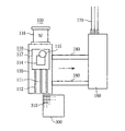
本発明の実施の形態の燃料検査装置(自明なときには、「検査装置」とも記す)を、図1から図3を参照しつつ説明する。図1は、検査対象の燃料集合体に本実施の形態の検査装置が設置されている状態を、側面から見た図である。図2は、同じく上部から見た図である。図3は、この検査装置において、超音波検査装置の上方にファイバースコープ検査装置が上下に重なって備え付けられている様子を、即ち要部の構造を概念的に示す図である。 A fuel inspection apparatus according to an embodiment of the present invention (also referred to as “inspection apparatus” when obvious) will be described with reference to FIGS. 1 to 3. FIG. 1 is a side view showing a state in which the inspection apparatus of the present embodiment is installed in a fuel assembly to be inspected. FIG. 2 is also a view from above. FIG. 3 is a diagram conceptually showing a state in which the fiberscope inspection apparatus is provided above and below the ultrasonic inspection apparatus in this inspection apparatus, that is, the structure of the main part.
図1から図3において、100は燃料検査装置であり、110はファイバースコープ検査装置であり、111はファイバースコープヘッドであり、112はスライドユニットであり、113はボールねじであり、114はファイバースコープを固定し、併せて回転角度等の調整を行うためのファイバースコープ微調整部であり、115はファイバースコープヘッド手動回転ツールアタッチメントであり、116は水中モータ部(モータがチャンバの中に入っている)であり、117はファイバースコープヘッドの設置台である。120は、ファイバースコープ検査装置の設置台である。
In FIG. 1 to FIG. 3, 100 is a fuel inspection device, 110 is a fiberscope inspection device, 111 is a fiberscope head, 112 is a slide unit, 113 is a ball screw, and 114 is a fiberscope. Is a fiberscope fine adjustment unit for adjusting the rotation angle and the like, 115 is a fiberscope head manual rotation tool attachment, and 116 is a submersible motor unit (the motor is in the chamber). 117 is an installation base for the fiberscope head.
130は超音波検査装置であり、131は発信子側のプローブであり、132は受信子側のプローブであり、133はスライドユニットであり、134はボールねじであり、135は発信子側と受信子側の超音波プローブ131、132の固定部であり、136は水中モータ部であり、137は超音波プローブの固定部135の設置台であり、140は検査装置の設置台である。
また、160はモータのドライバーやシーケンサデバイス等の制御系電子機器の収納箱であり、170は動力用の線であり、180は横移動用のレールである。
130 is an ultrasonic inspection apparatus, 131 is a probe on the transmitter side, 132 is a probe on the receiver side, 133 is a slide unit, 134 is a ball screw, and 135 is received on the transmitter side. The child-side
なお、300は燃料集合体であり、310は燃料棒であり、320は支持グリッドであり、400は使用済み燃料ラックであるが、これらは本発明の趣旨に直接の関係がないため、説明は省略する。
以上の他、検査装置には退避ユニット等が装備され、近くには水中カメラ等が設置され、さらに燃料集合体を上方に釣り上げるクレーン等もあるが、これらは自明であり、また図面が細かくなりすぎるため、図示はしていない。
In addition, although 300 is a fuel assembly, 310 is a fuel rod, 320 is a support grid, 400 is a spent fuel rack, but since these are not directly related to the gist of the present invention, the explanation is omitted. Omitted.
In addition to the above, the inspection device is equipped with a evacuation unit, etc., and an underwater camera etc. is installed nearby, and there are cranes that lift the fuel assembly upward, but these are self-explanatory and the drawings become finer. It is not shown because it is too much.
図1に示す様に、図示しないクレーンにより使用済み燃料ラックから吊り上げられた状態の燃料集合体300のある特定のスパン(上下の支持グリッド320の間)の側面に燃料検査装置100がセッティングされている。この状態で、クレーンにより燃料集合体300は上下方向に移動して検査対象のスパンを変更したり、90度ずつ回転して燃料検査装置100に対向する側面を変えたりすることが可能となっている。
図2は、この状態を上方から見た様子を示す図である。燃料検査装置100は、横移動用のレール180により図で右方に移動することが可能であり、これにより検査対象の燃料棒の行あるいは列を変更することが可能である。
As shown in FIG. 1, the
FIG. 2 is a diagram showing a state in which this state is viewed from above. The
図3は、ファイバースコープ燃料検査装置110を上方に、超音波検査装置130を下方にして、燃料検査装置100のセンサー部が一体に組立てられている様子を概念的に示す図である。ファイバースコープ検査装置110は専用の設置台120に設置され、超音波検査装置130は直接検査装置の設置台140に設置され、前者の設置台120は後者の設置台140に固定されている。そして、ファイバースコープ検査装置110は、遠隔操作で水中モータ部116が正、逆の回転操作をなされることによりボールねじ113も正、逆の回転を行い、図示しないラック機構の作用でスライドユニット112にガイドされつつ燃料集合体の方に近づいたり、離れたりする。そして、これに伴い、ファイバースコープヘッド111を燃料集合体300内へ出し入れすることが可能となっている。同様に、超音波検査装置130も発信子側のプローブ131と受信子側のプローブ132を出し入れすることが可能になっている。
FIG. 3 is a diagram conceptually illustrating a state in which the sensor unit of the
なお、図3はファイバースコープ検査装置110と超音波検査装置130が一体に組立てられている様子を明瞭に示すための概念図であり、このため両方の検査装置のスライドユニット112、133は直線状に記載しているが、実際には両端は下方に折れ曲がって設置台120、140に固定されている。また同様に、2つの水中モータ部116、136は、いずれも対応する設置台120、140に固定されている。
FIG. 3 is a conceptual diagram for clearly showing a state in which the
ファイバースコープ検査装置110が上方にあるため、そのファイバースコープヘッド手動回転ツールアタッチメント115は最上部にあり、図2に示す様にプールの上から見つつ治具(図示せず)で回転操作をすることができる。このため、破損箇所やその周辺をファイバースコープにより精密に観察することが可能となっている。
Since the
(第2の実施の形態)
本実施の形態は、ファイバースコープ検査装置110と超音波検査装置130の駆動装置(水中モータ部等)が共通となった検査装置に関する。
本第2の実施の形態の燃料検査装置の駆動装置(水中モータ)の切り替え機構の原理を、図4に示す。
(Second Embodiment)
The present embodiment relates to an inspection apparatus in which a drive device (such as an underwater motor unit) of the
The principle of the switching mechanism of the drive device (submersible motor) of the fuel inspection device of the second embodiment is shown in FIG.
図4において、150は兼用の水中モータ部であり、151は後部歯車であり、152は前部歯車であり、153は上部歯車であり、154は下部歯車であり、155は上部クラッチ制御部であり、156は下部クラッチ制御部であり、157は上部クラッチであり、158は下部クラッチである。また、122は上部クラッチ制御部155の支持腕であり、123は上部歯車153と上部クラッチ157の支持部であり、124は上部クラッチ157の支持部であり、141は兼用の水中モータ部の架台であり、142は下部クラッチ制御部156の支持部であり、143は下部歯車154と下部クラッチ158の支持部であり、144は下部クラッチ158の支持部である。
In FIG. 4, 150 is a combined submersible motor unit, 151 is a rear gear, 152 is a front gear, 153 is an upper gear, 154 is a lower gear, and 155 is an upper clutch control unit. Yes, 156 is a lower clutch control unit, 157 is an upper clutch, and 158 is a lower clutch. Further, 122 is a support arm of the upper
図4に示す様に、兼用の水中モータ部150は、その架台141により検査装置の設置台140の端部に、ファイバースコープ検査装置(本体部分は図示せず)と超音波検査装置(本体部分は図示せず)の中間の高さに固定されている。そして、その軸には後部歯車151と前部歯車152が取付けられている。さらに、後部歯車151は上部歯車153と上部クラッチ157を介してファイバースコープ検査装置のボールねじ113を回転させることが可能であり、前部歯車152は下部歯車154と下部クラッチ158を介して超音波検査装置のボールねじ134を回転させることが可能である。このため、兼用の水中モータ部150の正、逆の回転に伴って、ファイバースコープ検査装置(本体部分は図示せず)と超音波検査装置(本体部分は図示せず)は、燃料集合体(図示せず)の方に接近したり、反対側に後退したりすることとなる。
As shown in FIG. 4, the dual-purpose
また、各部の回転、トルク伝達を円滑に行うため、上部クラッチ制御部155、下部クラッチ制御部156、上部クラッチ制御部155の支持腕122、上部歯車153と上部クラッチ157の支持部123、上部クラッチ157の支持部124、下部クラッチ制御部156の支持部142、下部歯車154と下部クラッチ158の支持部143、下部クラッチ158の支持部144内には、水中用軸受け(図示せず)が内蔵されている。
Further, in order to smoothly rotate each part and transmit torque, the upper
さらに、上部クラッチ制御部155は、図示しない制御線からの信号により、両矢印に示す方向(図面で左右方向)に上部歯車153と上部クラッチ157を動かすことが可能であり、これによりファイバースコープ検査装置のボールねじ113との結合、解除を遠隔操作で行うことが可能となっている。同じく、下部クラッチ制御部156は、図示しない制御線からの信号により、両矢印に示す方向に下部歯車154と下部クラッチ158を動かすことが可能であり、これにより超音波検査装置のボールねじ134との結合、解除を遠隔操作で行なうことが可能となっている。
Further, the upper
本第2の実施の形態の検査装置においては、最初に超音波検査がなされるため、下部クラッチ158は結合状態、上部クラッチ157は解除状態とされる。次いで、ファイバースコープによる観察がなされるため、下部クラッチ158は解除状態、上部クラッチ157は結合状態とされる。
本実施の形態の検査装置には、上下両方のクラッチ157、158が同時に結合状態となって、水中モータ部に過負荷がかかることを防止するための安全装置等をも組み込んでいるが、これは周知技術であるため、図示や説明は省略する。
In the inspection apparatus according to the second embodiment, since the ultrasonic inspection is first performed, the
The inspection apparatus according to the present embodiment incorporates a safety device and the like for preventing both the upper and
100 燃料検査装置
110 ファイバースコープ検査装置
111 ファイバースコープ(ヘッド)
112 スライドユニット
113 ボールねじ
114 ファイバースコープ微調整部
115 ファイバースコープヘッド手動回転ツールアタッチメント
116 水中モータ部
117 ファイバースコープヘッドの設置台
120 ファイバースコープ検査装置の設置台
122 上部クラッチ制御部の支持腕
123 上部歯車と上部クラッチの支持部
124 上部クラッチの支持部
130 超音波検査装置
131 発信子側のプローブ
132 受信子側のプローブ
133 スライドユニット
134 ボールねじ
135 超音波プローブの固定部
136 水中モータ部
137 超音波プローブの固定部の設置台
140 検査装置の設置台
141 兼用の水中モータ部の架台
142 下部クラッチ制御部の支持部
143 下部歯車と下部クラッチの支持部
144 下部クラッチの支持部
150 兼用の水中モータ部
151 後部歯車
152 前部歯車
153 上部歯車
154 下部歯車
155 上部クラッチ制御部
156 下部クラッチ制御部
157 上部クラッチ
158 下部クラッチ
160 収納箱
170 動力用の線
180 横移動用のレール
300 燃料集合体
310 健全な燃料棒(燃料棒)
311 破損した燃料棒
320 支持グリッド
321 横方向の格子板
322 縦方向の格子板
323 ディンプル部
400 使用済み燃料ラック
100
112
311
Claims (7)
前記第1本体部は、燃料集合体内に挿入される検出端を保持し、
前記第1設置台は、前記第1本体部を燃料集合体側の方向および反対側の方向に移動させる第1移動機構と、移動時に前記第1本体部の姿勢を保持させつつ支持する第1支持機構とを有し、
前記第1駆動部は、前記第1設置台に固定されており、前記第1移動機構を稼動させるものであり、
前記ファイバースコープ検査装置は、第2本体部と第2設置台と第2駆動部を有し、
前記第2本体部は、燃料集合体内に挿入されるファイバースコープを保持し、
前記第2設置台は、前記第2本体部を燃料集合体側の方向および反対側の方向に移動させる第2移動機構と、移動時に前記第2本体部の姿勢を保持させつつ支持する第2支持機構とを有し、
前記第2駆動部は、前記第2設置台に固定されており、前記第2移動機構を稼動させるものであり、
さらに前記第1設置台と前記第2設置台は相互に固定されていることを特徴とする請求項1ないし請求項3のいずれかに記載の燃料検査装置。 The ultrasonic inspection apparatus includes a first main body, a first installation base, and a first driving unit,
The first main body holds a detection end inserted into the fuel assembly,
The first installation base includes a first moving mechanism that moves the first main body portion in a fuel assembly side direction and an opposite direction, and a first support that holds the posture of the first main body portion while moving. A mechanism,
The first drive unit is fixed to the first installation base and operates the first moving mechanism.
The fiberscope inspection device has a second body part, a second installation base, and a second drive part,
The second main body holds a fiberscope inserted into the fuel assembly,
The second installation base includes a second moving mechanism that moves the second main body portion in the direction of the fuel assembly side and the opposite direction, and a second support that supports the second main body portion while maintaining the posture of the second main body portion during movement. A mechanism,
The second driving unit is fixed to the second installation base and operates the second moving mechanism.
The fuel inspection apparatus according to any one of claims 1 to 3, wherein the first installation base and the second installation base are fixed to each other.
前記第1本体部は、燃料集合体内に挿入される検出端を保持し、
前記第1設置台は、前記第1本体部を燃料集合体側の方向および反対側の方向に移動させる第1移動機構と、移動時に前記第1本体部の姿勢を保持させつつ支持する第1支持機構とを有し、
前記第1切替え装置は、前記第1移動機構と前記駆動部間の駆動力の伝達のオン、オフの切替えを行い、
前記ファイバースコープ検査装置と共有する駆動部は、前記第1設置台に固定されており、前記第1切替え装置を介して前記第1移動機構を稼動させるものであり、
前記ファイバースコープ検査装置は、第2本体部と第2設置台と第2切替え装置と前記超音波検査装置と共有する駆動部を有し、
前記第2本体部は、燃料集合体内に挿入されるファイバースコープを保持し、
前記第2設置台は、前記第2本体部を燃料集合体側の方向および反対側の方向に移動させる第2移動機構と、移動時に前記第2本体部の姿勢を保持させつつ支持する第2支持機構とを有し、
前記第2切り替え装置は、前記第2移動機構と前記駆動部間の駆動力の伝達のオン、オフの切替えを行い、
前記超音波検査装置と共有する駆動部は、前記第2設置台にも固定されており、前記第2切替え装置を介して前記第2移動機構を稼動させるものであり、
さらに前記超音波検査装置の第1設置台と前記ファイバースコープ検査装置の第2設置台は相互に固定されていることを特徴とする請求項4に記載の燃料検査装置。 The ultrasonic inspection apparatus has a drive unit that is shared with the first main body, the first installation base, the first switching device, and the fiberscope inspection apparatus,
The first main body holds a detection end inserted into the fuel assembly,
The first installation base includes a first moving mechanism that moves the first main body portion in a fuel assembly side direction and an opposite direction, and a first support that holds the posture of the first main body portion while moving. A mechanism,
The first switching device performs on / off switching of transmission of driving force between the first moving mechanism and the driving unit,
The drive unit shared with the fiberscope inspection device is fixed to the first installation base, and operates the first moving mechanism via the first switching device.
The fiberscope inspection device has a second main body, a second installation base, a second switching device, and a drive unit shared with the ultrasonic inspection device,
The second main body holds a fiberscope inserted into the fuel assembly,
The second installation base includes a second moving mechanism that moves the second main body portion in the direction of the fuel assembly side and the opposite direction, and a second support that supports the second main body portion while maintaining the posture of the second main body portion during movement. A mechanism,
The second switching device performs on / off switching of transmission of driving force between the second moving mechanism and the driving unit,
The drive unit shared with the ultrasonic inspection apparatus is also fixed to the second installation base, and operates the second moving mechanism via the second switching device,
5. The fuel inspection apparatus according to claim 4, wherein the first installation base of the ultrasonic inspection apparatus and the second installation base of the fiberscope inspection apparatus are fixed to each other.
The first body portion of the ultrasonic inspection apparatus has a transmitter-side probe and a receiver-side probe that can be inserted into the fuel assembly with a row of fuel rods sandwiched therebetween and pulled out from the fuel assembly. The fuel inspection device according to claim 5 or 6, wherein a detection end of a broken fuel rod made of
Priority Applications (1)
| Application Number | Priority Date | Filing Date | Title |
|---|---|---|---|
| JP2006166676A JP2007333601A (en) | 2006-06-15 | 2006-06-15 | Fuel inspection system |
Applications Claiming Priority (1)
| Application Number | Priority Date | Filing Date | Title |
|---|---|---|---|
| JP2006166676A JP2007333601A (en) | 2006-06-15 | 2006-06-15 | Fuel inspection system |
Publications (1)
| Publication Number | Publication Date |
|---|---|
| JP2007333601A true JP2007333601A (en) | 2007-12-27 |
Family
ID=38933207
Family Applications (1)
| Application Number | Title | Priority Date | Filing Date |
|---|---|---|---|
| JP2006166676A Pending JP2007333601A (en) | 2006-06-15 | 2006-06-15 | Fuel inspection system |
Country Status (1)
| Country | Link |
|---|---|
| JP (1) | JP2007333601A (en) |
Cited By (2)
| Publication number | Priority date | Publication date | Assignee | Title |
|---|---|---|---|---|
| CN108269628A (en) * | 2016-12-30 | 2018-07-10 | 核动力运行研究所 | A kind of ultrasonic inspection apparatus of square arrangement damaged fuel assembly |
| KR20190039362A (en) * | 2017-09-29 | 2019-04-11 | 유저스(주) | Apparatus for measuring data of nuclear fuel tube assembly and a method using the device |
Citations (10)
| Publication number | Priority date | Publication date | Assignee | Title |
|---|---|---|---|---|
| JPS58214888A (en) * | 1982-05-27 | 1983-12-14 | ブラウン・ボベリ・レアクト−ル・ゲゼルシヤフト・ミト・ベシユレンクテル・ハフツング | Device for detecting fuel element , especially for detecting failed fuel rod in water cooled reactor |
| JPS61164152A (en) * | 1985-01-16 | 1986-07-24 | Nippon Atom Ind Group Co Ltd | Inspecting installation |
| JPH03123891A (en) * | 1989-10-06 | 1991-05-27 | Toshiba Corp | Automatic fuel inspecting device |
| JPH03277995A (en) * | 1990-03-28 | 1991-12-09 | Toshiba Corp | Apparatus for observing interior of fuel bundle |
| JPH04104004A (en) * | 1990-08-23 | 1992-04-06 | Nippon Nuclear Fuel Dev Co Ltd | Measuring method for fuel element interval |
| JPH04256896A (en) * | 1991-02-07 | 1992-09-11 | Toshiba Corp | Observing device for inside of fuel assembly |
| JPH04319660A (en) * | 1991-04-18 | 1992-11-10 | Mitsubishi Heavy Ind Ltd | Method for detecting damaged pipe by ultrasonic inspection |
| JPH04350598A (en) * | 1991-05-28 | 1992-12-04 | Toshiba Corp | Inspection device of fuel assembly |
| JPH09145886A (en) * | 1995-11-21 | 1997-06-06 | Toshiba Eng Co Ltd | Travelling in-core monitor driving device with cutter |
| JP2006141624A (en) * | 2004-11-18 | 2006-06-08 | Olympus Corp | Endoscope |
-
2006
- 2006-06-15 JP JP2006166676A patent/JP2007333601A/en active Pending
Patent Citations (10)
| Publication number | Priority date | Publication date | Assignee | Title |
|---|---|---|---|---|
| JPS58214888A (en) * | 1982-05-27 | 1983-12-14 | ブラウン・ボベリ・レアクト−ル・ゲゼルシヤフト・ミト・ベシユレンクテル・ハフツング | Device for detecting fuel element , especially for detecting failed fuel rod in water cooled reactor |
| JPS61164152A (en) * | 1985-01-16 | 1986-07-24 | Nippon Atom Ind Group Co Ltd | Inspecting installation |
| JPH03123891A (en) * | 1989-10-06 | 1991-05-27 | Toshiba Corp | Automatic fuel inspecting device |
| JPH03277995A (en) * | 1990-03-28 | 1991-12-09 | Toshiba Corp | Apparatus for observing interior of fuel bundle |
| JPH04104004A (en) * | 1990-08-23 | 1992-04-06 | Nippon Nuclear Fuel Dev Co Ltd | Measuring method for fuel element interval |
| JPH04256896A (en) * | 1991-02-07 | 1992-09-11 | Toshiba Corp | Observing device for inside of fuel assembly |
| JPH04319660A (en) * | 1991-04-18 | 1992-11-10 | Mitsubishi Heavy Ind Ltd | Method for detecting damaged pipe by ultrasonic inspection |
| JPH04350598A (en) * | 1991-05-28 | 1992-12-04 | Toshiba Corp | Inspection device of fuel assembly |
| JPH09145886A (en) * | 1995-11-21 | 1997-06-06 | Toshiba Eng Co Ltd | Travelling in-core monitor driving device with cutter |
| JP2006141624A (en) * | 2004-11-18 | 2006-06-08 | Olympus Corp | Endoscope |
Cited By (4)
| Publication number | Priority date | Publication date | Assignee | Title |
|---|---|---|---|---|
| CN108269628A (en) * | 2016-12-30 | 2018-07-10 | 核动力运行研究所 | A kind of ultrasonic inspection apparatus of square arrangement damaged fuel assembly |
| CN108269628B (en) * | 2016-12-30 | 2023-10-20 | 核动力运行研究所 | Ultrasonic inspection device for square arranged damaged fuel assemblies |
| KR20190039362A (en) * | 2017-09-29 | 2019-04-11 | 유저스(주) | Apparatus for measuring data of nuclear fuel tube assembly and a method using the device |
| KR102044441B1 (en) * | 2017-09-29 | 2019-11-13 | 유저스(주) | Apparatus for measuring data of nuclear fuel tube assembly and a method using the device |
Similar Documents
| Publication | Publication Date | Title |
|---|---|---|
| KR100713954B1 (en) | Remotely operated head inspection system | |
| US20200350087A1 (en) | Apparatus and method to remotely inspect piping and piping attachment welds | |
| KR101160659B1 (en) | heat pipe inspection robot of steam generation for nuclear power generation | |
| JPH1114784A (en) | Reactor internal inspecting device | |
| JP5113837B2 (en) | Preventive maintenance / repair device and preventive maintenance / repair method | |
| JP2007003400A (en) | Inspection device for control rod through-hole member | |
| JP2007333601A (en) | Fuel inspection system | |
| KR101721383B1 (en) | Apparatus for non-destructive inspection | |
| US20200350086A1 (en) | Inspection tool | |
| JP2000075080A (en) | Jet pump inspection device and treatment device | |
| JP2007155402A (en) | Device for inspecting reactor core internal structure | |
| KR101206789B1 (en) | Pipe cutting device for frame of spent nuclear fuel assembly | |
| EP2435296B1 (en) | An inspection apparatus | |
| KR101985386B1 (en) | Radiation source devices | |
| JPH0238995A (en) | In-furnace visual inspection device | |
| JP2009098105A (en) | Device for inspecting and repairing inside of nuclear reactor, and control method therefor | |
| US9793016B2 (en) | Inspection method and inspection device | |
| JP2002090490A (en) | Upper grid plate inspection device | |
| KR101128544B1 (en) | Remote Detecting Assembly to Sense Defect and Assembling Method thereof | |
| JP3886760B2 (en) | In-furnace inspection repair device and method | |
| KR101132874B1 (en) | Detecting Apparatus to Sense Defect and Detecting Method thereof | |
| JP4546746B2 (en) | Inspection device, inspection device input device, and inspection method | |
| JP3518824B2 (en) | Furnace structure visual inspection device | |
| KR20130046927A (en) | Unit for testing drill and method for testing drill | |
| JP2009270992A (en) | Radiographic testing device |
Legal Events
| Date | Code | Title | Description |
|---|---|---|---|
| A621 | Written request for application examination |
Free format text: JAPANESE INTERMEDIATE CODE: A621 Effective date: 20080526 |
|
| A977 | Report on retrieval |
Free format text: JAPANESE INTERMEDIATE CODE: A971007 Effective date: 20100803 |
|
| A131 | Notification of reasons for refusal |
Free format text: JAPANESE INTERMEDIATE CODE: A131 Effective date: 20110531 |
|
| A02 | Decision of refusal |
Free format text: JAPANESE INTERMEDIATE CODE: A02 Effective date: 20111011 |