JP2007298400A - Flow sensor - Google Patents
Flow sensor Download PDFInfo
- Publication number
- JP2007298400A JP2007298400A JP2006126763A JP2006126763A JP2007298400A JP 2007298400 A JP2007298400 A JP 2007298400A JP 2006126763 A JP2006126763 A JP 2006126763A JP 2006126763 A JP2006126763 A JP 2006126763A JP 2007298400 A JP2007298400 A JP 2007298400A
- Authority
- JP
- Japan
- Prior art keywords
- flow rate
- detected
- fluid
- integrated
- value
- Prior art date
- Legal status (The legal status is an assumption and is not a legal conclusion. Google has not performed a legal analysis and makes no representation as to the accuracy of the status listed.)
- Pending
Links
Images


Abstract
Description
本発明は、被検出流体の流量を検出する流量センサに関する。 The present invention relates to a flow sensor that detects a flow rate of a fluid to be detected.
従来より、液体や気体等の流体の流量を検出するために種々の流量センサが用いられている。例えば被検出流体を羽根車に当てて、その回転数を流量値に換算する羽根車式や、鉛直方向に設置されたパイプ中に浮きを配置し、この浮きの上昇度合いで流量を検出する浮き子式、ファラデーの電磁誘導の原理を使用して、流路内に可動部や障害物を配置することなく流量を測定可能な電磁式等がある。この内、電磁流量計には大別して接液電極形と非接液電極形の2種類が存在する。接液電極形の電磁流量計(接液式あるいは電極式電磁流量計等と呼ばれる)は、電極が被検出流体と直接接触し、被検出流体に発生する起電力を直接検出する。一方、非接液電極形の電磁流量計((静電)容量式電磁流量計等と呼ばれる)は、電極が被検出流体と直接接触せず、被検出流体に発生する起電力を被検出流体と電極間の静電容量を介して検出する。このような電磁流量計では被検出流体の経路が貫通構造であり、メンテナンス性に優れる。特に容量式電磁流量計では、測定管内面に電極が露出しないので、電極表面に付着するスケールの掃除等の作業を無くし、維持管理の手間を大幅に省力化できる利点が得られる。 Conventionally, various flow rate sensors have been used to detect the flow rate of fluid such as liquid or gas. For example, an impeller type that applies the fluid to be detected to the impeller and converts the rotation speed into a flow rate value, or a float is placed in a pipe installed in the vertical direction. There are a child type, an electromagnetic type that can measure a flow rate without disposing a moving part or an obstacle in the flow path by using the principle of electromagnetic induction of Faraday. Among these, there are two types of electromagnetic flowmeters: a wetted electrode type and a non-wetted electrode type. A wetted electrode type electromagnetic flow meter (referred to as a wetted type or an electrode type electromagnetic flow meter or the like) directly detects an electromotive force generated in the fluid to be detected by directly contacting the electrode with the fluid to be detected. On the other hand, a non-wetted electrode type electromagnetic flow meter (referred to as an (electrostatic) capacity type electromagnetic flow meter) has an electrode that does not directly contact the fluid to be detected and generates an electromotive force generated in the fluid to be detected. And detecting through the capacitance between the electrodes. In such an electromagnetic flow meter, the path of the fluid to be detected has a through structure, and is excellent in maintainability. In particular, in the capacitive electromagnetic flow meter, since the electrode is not exposed on the inner surface of the measuring tube, there is an advantage that work such as cleaning of the scale adhering to the electrode surface can be eliminated and labor for maintenance can be saved greatly.
このような流量センサの一例として、接液式電磁流量計900の構成を図26に示す。この図に示す電磁流量計900は、測定管911、電極903および励磁コイル922等からなる流量検出手段901、交流増幅器902、励磁回路924、同期整流回路904、タイミングパルス発生回路905、A/D変換器906、演算処理を行うマイクロコンピュータ等の制御部940、出力部908、表示部951および交流電源910等より構成される。図26の構成において、被測定流体は測定管911内を流れるが、この流体の流れる方向に対して垂直に励磁回路924および励磁コイル922を介して交番磁界を印加する。励磁回路924は、タイミングパルス発生回路905からの励振パルスにより駆動される。これにより、1対の電極903間に起電力が発生するので、この起電力を交流増幅器902で増幅し、同期整流回路904において同期整流する。この同期は、タイミングパルス発生回路905から与えられるタイミングパルスによって行われる。同期整流回路904の出力はA/D変換器906でデジタル量に変換され、制御部940に与えられる。制御部940では所定の処理を実行し、出力部908を介して流量の瞬時出力又は積算出力を出力し、表示部951に瞬時流量、積算流量等を表示する。
As an example of such a flow sensor, the configuration of a wetted
このように流量センサは、使用目的に従って瞬時流量、積算流量等の測定値を表示部に表示する機能を備えている。ここで積算流量とは、単純に流量の積算値をカウントし、累積値として表示するものであった。また積算値の初期値は0であり、順次加算されて表示される方式が採用されていた。
一方、流量センサが使用される用途によっては、所定の目的値まであとどのくらい余裕があるのかを知りたいような場合も存在する。例えば図27に示すように、貯水タンク810内の液体の残量を、排水パイプ820に接続した流量計800で検出したい場合は、排水パイプ820を通過する液体の流量を流量計800で測定して、表示部に積算流量を表示させ、貯水タンク810内の当初の水量から積算流量を減算することで計算できる。図27の例では、容量100リットルの貯水タンク810が満水の状態から、排水パイプ820から液体を排出しており、ある時点で表示部に表示された積算流量が20リットルとすれば、貯水タンク810内の残量は(100リットル)−(20リットル)=80リットルと計算できる。
On the other hand, depending on the application in which the flow sensor is used, there is a case where it is desired to know how much room is left until a predetermined target value. For example, as shown in FIG. 27, when the remaining amount of liquid in the
しかしながら、この方法では残量をリアルタイムで把握するために一々計算する必要があり、面倒であった。一方で従来の流量センサでは、検出・表示すべき流量として、瞬時流量、若しくは積算値をカウントするという概念しかなく、貯水タンク内の残量といった所定値までの余裕量を直接表示することができず、数値表示の柔軟性に欠けるものであった。 However, in this method, it is necessary to calculate the remaining amount in real time, which is troublesome. On the other hand, the conventional flow rate sensor has only the concept of counting an instantaneous flow rate or an integrated value as a flow rate to be detected and displayed, and can directly display a margin amount up to a predetermined value such as the remaining amount in the water storage tank. Therefore, the flexibility of numerical display was lacking.
また一方で、流量センサには積算流量をリセットするためのリセット信号を入力する機能を備えるものがある。リセット機能の概要を図21に示す。この図に示すように、外部からあるいはユーザ操作によりリセット信号を受けると、積算流量がリセットされて、再び0からカウントアップする。この仕様は固定されているため、例えばリセット後の積算値を所望の値に変更することは従来の流量センサではできなかった。特に上述の通り、従来は積算値を減算するという概念がなかったため、リセット信号に対しては0にすることしかできず、種々の用途や要求に対して柔軟性に欠けるものであった。 On the other hand, some flow sensors have a function of inputting a reset signal for resetting the integrated flow rate. An outline of the reset function is shown in FIG. As shown in this figure, when a reset signal is received from the outside or by a user operation, the integrated flow rate is reset and starts counting up again from zero. Since this specification is fixed, for example, a conventional flow sensor cannot change the integrated value after resetting to a desired value. In particular, as described above, since there was no concept of subtracting the integrated value in the past, the reset signal could only be set to 0, and lacked flexibility for various uses and requirements.
加えて、流量センサでは積算値とタイムアウト機能を組み合わせた制御を行うこともできなかった。タイムアウト機能とは、入力待ち状態が一定時間経過しても継続するような場合に、処理を中断する機能である。例えば一定時間経過しても所定の積算値に達しないような場合に異常を検出して、処理を中断するような動作を、流量センサのみで実現することはできず、PLC等を用いたシーケンスの設定が必要となり、機構が煩雑になるという問題があった。 In addition, the flow sensor could not perform control combining the integrated value and the timeout function. The time-out function is a function that interrupts processing when the input waiting state continues even after a predetermined time has elapsed. For example, when a predetermined integrated value is not reached even after a certain period of time, an operation that detects an abnormality and interrupts the processing cannot be realized with only a flow sensor, and a sequence using a PLC or the like. Therefore, there is a problem that the mechanism becomes complicated.
本発明は、従来のこのような課題に鑑みてなされたものである。本発明の一の目的は、用途に応じて種々の態様で積算値を表示可能とした流量センサを提供することにある。 The present invention has been made in view of such conventional problems. An object of the present invention is to provide a flow sensor that can display integrated values in various modes according to the application.
以上の目的を達成するために、第1発明に係る流量センサは、被検出流体の流量を検出するための流量センサであって、本体ケースと、前記本体ケース内に配設されて、被検出流体を通過させるための管状の測定管と、前記測定管を流れる被検出流体の流量を検出可能な流量検出手段と、前記流量検出手段で検出された被検出流体の流量に基づき、積算流量を演算可能な流量演算部と、前記流量演算部で演算された積算流量を表示可能な表示部と、前記流量演算値で演算された積算流量を保持するためのメモリ部と、リセット信号を受信すると、前記メモリ部に保持された積算流量を所定のリセット値にリセットするリセット信号入力部と、前記所定のリセット値を設定するためのリセット設定部とを備え、予め設定された所定値から積算流量を減算した減算値を、前記表示部に表示可能に構成している。 In order to achieve the above object, a flow sensor according to a first aspect of the present invention is a flow sensor for detecting a flow rate of a fluid to be detected, and is disposed in the body case and the body case. Based on the flow rate of the fluid to be detected, the flow rate detection means capable of detecting the flow rate of the fluid to be detected flowing through the measurement pipe, and the flow rate of the fluid to be detected detected by the flow rate detection means, the integrated flow rate is calculated. When receiving a reset signal, a flow rate calculation unit that can be calculated, a display unit that can display the integrated flow rate calculated by the flow rate calculation unit, a memory unit that holds the integrated flow rate calculated by the flow rate calculation value, A reset signal input unit for resetting the integrated flow rate held in the memory unit to a predetermined reset value, and a reset setting unit for setting the predetermined reset value, and the integrated flow from the predetermined value set in advance A subtraction value obtained by subtracting the, are capable of displaying on the display unit.
第2発明に係る流量センサは、リセット信号が、外部入力若しくはユーザの指定により入力可能に構成されている。 The flow rate sensor according to the second aspect of the invention is configured such that the reset signal can be input by an external input or user designation.
第3発明に係る流量センサは、流量演算値で演算された積算流量を、所定のリセット値から減算した減算値を、表示部に表示可能に構成している。 The flow rate sensor according to the third aspect of the invention is configured so that a subtracted value obtained by subtracting the integrated flow rate calculated by the flow rate calculated value from a predetermined reset value can be displayed on the display unit.
第4発明に係る流量センサは、被検出流体の流量を検出するための流量センサであって、本体ケースと、本体ケース内に配設されて、被検出流体を通過させるための管状の測定管と、測定管を流れる被検出流体の流量を検出可能な流量検出手段と、流量検出手段で検出された被検出流体の流量に基づき、積算流量を演算可能な流量演算部と、積算流量が所定値に達した際に所定の積算値出力を変更可能な積算値出力部と、予め設定された所定の時間内に積算値出力部が積算値出力を変更しない場合に、所定のタイムアウト出力を出力可能なタイムアウト出力部とを備える。 A flow rate sensor according to a fourth aspect of the invention is a flow rate sensor for detecting a flow rate of a fluid to be detected, and a main body case and a tubular measuring tube that is disposed in the main body case and allows the fluid to be detected to pass therethrough. A flow rate detection means capable of detecting the flow rate of the fluid to be detected flowing through the measuring tube, a flow rate calculation unit capable of calculating an integrated flow rate based on the flow rate of the detected fluid detected by the flow rate detection means, and a predetermined integrated flow rate An integrated value output unit that can change the predetermined integrated value output when reaching the value, and a predetermined time-out output when the integrated value output unit does not change the integrated value output within a preset predetermined time Possible timeout output unit.
第5発明に係る流量センサは、被検出流体の流量を検出するための流量センサであって、本体ケースと、本体ケース内に配設されて、被検出流体を通過させるための管状の測定管と、測定管を流れる被検出流体の流量を検出可能な流量検出手段と、流量検出手段で検出された被検出流体の流量に基づき、積算流量を演算可能な流量演算部と、予め設定された所定値から積算流量を減算した減算値を表示可能な表示部と、積算流量が所定値に達した際に所定の積算値出力を出力可能な積算値出力部と、予め設定された所定の時間内に積算値出力部が積算値出力を出力しない場合に、所定のタイムアウト出力を出力可能なタイムアウト出力部とを備える。 A flow rate sensor according to a fifth aspect of the present invention is a flow rate sensor for detecting a flow rate of a fluid to be detected, and a main body case, and a tubular measuring tube disposed in the main body case for allowing the fluid to be detected to pass therethrough. And a flow rate detection means capable of detecting the flow rate of the fluid to be detected flowing through the measurement tube, a flow rate calculation unit capable of calculating the integrated flow rate based on the flow rate of the fluid to be detected detected by the flow rate detection means, and a preset value A display unit that can display a subtracted value obtained by subtracting the integrated flow rate from a predetermined value, an integrated value output unit that can output a predetermined integrated value output when the integrated flow rate reaches a predetermined value, and a preset predetermined time And a time-out output unit capable of outputting a predetermined time-out output when the integrated value output unit does not output the integrated value output.
第6発明に係る流量センサは、流量検出手段が、被検出流体に交番磁場を印加するための磁場印加手段と、被検出流体と非接触となるよう測定管と結合される電極と、測定管を通過する被検出流体の流量を演算する演算手段とを備える。 According to a sixth aspect of the present invention, there is provided the flow rate sensor, wherein the flow rate detection means is a magnetic field application means for applying an alternating magnetic field to the fluid to be detected, an electrode coupled to the measurement tube so as to be in non-contact with the fluid to be detected, And a calculating means for calculating the flow rate of the fluid to be detected that passes through.
第1発明によれば、所定値までの余裕量を表示部に直接表示させることができ、ユーザは計算等をすることなく知りたい値を表示部で直視して確認できる。また第1発明及び第2発明によれば、リセット信号を受信した後の積算流量を、0に限られず任意の値に設定できるので、より柔軟な数値表示が可能となる。 According to the first invention, the margin up to the predetermined value can be directly displayed on the display unit, and the user can confirm the desired value by directly viewing on the display unit without performing calculation or the like. Further, according to the first and second inventions, the integrated flow rate after receiving the reset signal can be set to an arbitrary value without being limited to 0, so that a more flexible numerical display is possible.
第3発明によれば、リセット値までの余裕量を表示部に直接表示させることができ、ユーザは計算等をすることなく知りたい値を表示部で直視して確認できる。例えば貯水タンク内の残水量を直読したり、容器に液体を充填する用途においては、あとどれだけ充填すればよいかを判定したりする用途に好適に利用できる。 According to the third invention, the margin to the reset value can be directly displayed on the display unit, and the user can confirm the desired value by directly viewing on the display unit without performing calculation or the like. For example, in the use of directly reading the amount of remaining water in the water storage tank or filling the container with the liquid, it can be suitably used for the purpose of determining how much more to fill.
第4発明によれば、所定の時間内に積算値出力の変化がない場合は、タイムアウト出力を出力することにより、流量センサのみで異常を判別できる。例えば貯水タンクに水を補充する用途において、所定時間内に補充することができないことを検出して、貯水タンクの破損等の異常を、流量センサ単体で検出できる。 According to the fourth aspect of the present invention, when there is no change in the integrated value output within a predetermined time, an abnormality can be determined only by the flow rate sensor by outputting a timeout output. For example, in an application of replenishing water in a water storage tank, it is possible to detect that the water tank cannot be replenished within a predetermined time, and an abnormality such as damage to the water storage tank can be detected by a single flow sensor.
第5発明によれば、所定の時間内に積算値出力がない場合は、タイムアウト出力を出力することにより、流量センサのみで異常を判別できる。例えば貯水タンクに水を補充する用途において、所定時間内に補充することができないことを検出して、貯水タンクの破損等の異常を、流量センサ単体で検出できる。 According to the fifth aspect of the present invention, when there is no integrated value output within a predetermined time, an abnormality can be determined only by the flow rate sensor by outputting a timeout output. For example, in an application of replenishing water in a water storage tank, it is possible to detect that the water tank cannot be replenished within a predetermined time, and an abnormality such as damage to the water storage tank can be detected by a single flow sensor.
第6発明によれば、容量式電磁流量計で積算流量を測定する際の柔軟性を向上できる。 According to the sixth aspect of the invention, the flexibility when measuring the integrated flow rate with the capacitive electromagnetic flow meter can be improved.
以下、本発明の実施の形態を図面に基づいて説明する。ただし、以下に示す実施の形態は、本発明の技術思想を具体化するための流量センサを例示するものであって、本発明は流量センサを以下のものに特定しない。また、本明細書は特許請求の範囲に示される部材を、実施の形態の部材に特定するものでは決してない。特に実施の形態に記載されている構成部品の寸法、材質、形状、その相対的配置等は特に特定的な記載がない限りは、本発明の範囲をそれのみに限定する趣旨ではなく、単なる説明例にすぎない。なお、各図面が示す部材の大きさや位置関係等は、説明を明確にするため誇張していることがある。さらに以下の説明において、同一の名称、符号については同一もしくは同質の部材を示しており、詳細説明を適宜省略する。さらに、本発明を構成する各要素は、複数の要素を同一の部材で構成して一の部材で複数の要素を兼用する態様としてもよいし、逆に一の部材の機能を複数の部材で分担して実現することもできる。
(実施の形態1)
Hereinafter, embodiments of the present invention will be described with reference to the drawings. However, the embodiment described below exemplifies a flow sensor for embodying the technical idea of the present invention, and the present invention does not specify the flow sensor as described below. Further, the present specification by no means specifies the members shown in the claims to the members of the embodiments. In particular, the dimensions, materials, shapes, relative arrangements, and the like of the component parts described in the embodiments are not intended to limit the scope of the present invention unless otherwise specified, and are merely explanations. It's just an example. Note that the size, positional relationship, and the like of the members shown in each drawing may be exaggerated for clarity of explanation. Further, in the following description, the same name and reference numeral indicate the same or the same members, and detailed description will be omitted as appropriate. Furthermore, each element constituting the present invention may be configured such that a plurality of elements are constituted by the same member and the plurality of elements are shared by one member, and conversely, the function of one member is constituted by a plurality of members. It can also be realized by sharing.
(Embodiment 1)
以下、流量センサとして容量式電磁流量計に適用した例を説明する。図1〜図19に、本発明の実施の形態1に係る容量式電磁流量計100を示す。これらの図において、図1は容量式電磁流量計100の構成を示すブロック図、図2は本体ケースの断面図、図3は容量式電磁流量計100の回路構成のさらに詳細なブロック図、図4は容量式電磁流量計の斜視図、図5は図4の容量式電磁流量計の表示ユニットを外した分解斜視図、図6は図5の本体ケースから口金と補強板を外した分解斜視図、図7はサイドカバーを本体カバーで固定する状態の分解斜視図、図8はハウジングを本体カバーで保持する状態の断面図、図9は測定管の斜視図及び電極を外した分解斜視図、図10は図6の本体ケースの分解斜視図、図11はプリアンプモジュールの分解斜視図、図12は励磁モジュールの斜視図、図13は励磁プレートの斜視図、図14は励磁コイルの分解斜視図、図15は一体型表示ユニットの分解斜視図、図16は本体ケースに、表示ユニットを固定する様子を示す斜視図、図17は分離型表示ユニットを使用した容量式電磁流量計の斜視図、図18は、この電磁流量計のブロック図、図19は分離型表示ユニットの分解斜視図を、それぞれ示している。
(ブロック図)
Hereinafter, an example in which the flow rate sensor is applied to a capacitive electromagnetic flow meter will be described. 1 to 19 show a capacitive
(Block Diagram)
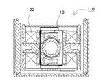
図1のブロック図及び図2の本体ケース断面図に示すように、容量式電磁流量計100は、被検出流体を通過させる測定管10と、ポールピース178の周囲に巻回され、測定管10の外部から被検出流体に磁場を印加する励磁コイル22と、励磁コイル22で交番磁界を発生させるための励磁回路24と、励磁コイル22で発生される磁界中を被検出流体が通過して発生される起電力を検出するための電極30と、電極30を介して起電力を検出する検出回路34と、励磁回路24及び検出回路34を駆動制御し、さらに検出された信号から流量を演算するための制御部40と、制御部40で演算された流量を表示する表示部51とを備える。この制御部40は、流量検出手段を構成する本体ケース110で検出された被検出流体の流量に基づき、積算流量を演算可能な流量演算部として機能する。また必要に応じて、出力信号を出力するための出力部60や、外部からのリセット信号等の各種入力信号を入力するための入力部70、各種設定を行うための設定部80等を設けてもよい。これら制御部40、表示部51、出力部60、入力部70、設定部80等は、表示ユニット50として、本体ケース110と別部材のユニット状に構成される。
As shown in the block diagram of FIG. 1 and the cross-sectional view of the main body case of FIG. 2, the capacitive
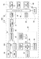
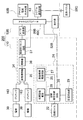
この容量式電磁流量計100の回路構成のさらに詳細なブロック図を図3に示す。この図では、容量式電磁流量計100を構成する本体ケース110と表示ユニット50各々について、これらを構成する部材を示している。まず本体ケース110側には、電極30とプリアンプ163を一対、測定管に配置している。そしてこれらの電極30で起電力を検出する検出回路34として、差動増幅器35と、増幅器36と、周期性リセット回路37を備える。図3の例では、プリアンプ163の出力は差動増幅器35に入力され、電極30間に発生した起電力を検出する。差動増幅器35の出力はさらに増幅器36で増幅されて、周期性リセット回路37を介して、A/D変換器38でA/D変換され、制御部40に入力される。周期性リセット回路37は、制御部40から周期的に送られるリセット信号を受けて、検出された電圧をリセットするための回路である。
A more detailed block diagram of the circuit configuration of the capacitive
一方、測定管に励磁コイル22で磁界を生じさせる励磁回路24としては、励磁用の励磁電源25、励磁コイル22と励磁電源25との間に介在され、励磁の極性を切り替える励磁極性切替回路28、及び励磁コイル22に所定の定電流を通電させるための定電流回路29を備える。この励磁回路24では、励磁極性切替回路28が励磁電源25より供給される電力をスイッチングして交流電流を励磁コイル22に供給し、交番磁界を発生させる。図3の例では、励磁電源25として、初期励磁電源26及び励磁継続電源27の2つを備えており、これらを切り替えて使用する。すなわち、励磁コイル22の立ち上げ時には高電圧が必要であるため、より高出力を得られる初期励磁電源26を使用する。そして励磁が安定すると、励磁を継続させるために必要な電圧は低くなるので、励磁継続電源27に切り替える。これにより、起動時の高電圧と安定動作時の定電圧とを供給するために、専用の電源を用意することで、電源が大型化したり電力損失が増すことを回避でき、装置の小型化や発熱防止が図られる。
On the other hand, as an
さらに、励磁極性切替回路28の出力は、表示ユニット50側の制御部40に入力される。表示ユニット50は、A/D変換器38と、制御部40と、表示部51と、設定部80と、入力部70と、出力部60を備える。制御部40は、マイクロコンピュータ等で構成され、これら励磁回路24と検出回路34を同期させて駆動、制御する。また設定部80は、各種の設定や操作を行うためのスイッチやコンソールである。表示部51は、7セグメント式表示器等を備え、検出された瞬時流量や積算流量、あるいは設定値などを切り替えて、又は同時に表示する。入力部70は、外部信号を入力する入力回路である。出力部60は、制御信号等を出力するための外部出力回路61とアナログ電流出力回路62を備える。
Further, the output of the excitation
なお、これら表示ユニットや本体ケース、あるいは励磁回路や検出回路などの区分けは一例であり、各構成部材が属するユニットや回路を適宜変更しても同様の機能が実現できることはいうまでもない。また、機能が実現される限りにおいて任意の部材を統合することも可能である。 It should be noted that the classification of the display unit, the main body case, the excitation circuit, the detection circuit, and the like is an example, and it goes without saying that the same function can be realized by appropriately changing the unit or circuit to which each constituent member belongs. Moreover, as long as a function is implement | achieved, it is also possible to integrate arbitrary members.
この容量式電磁流量計100の動作原理を、図1に基づいて説明する。被検出流体を導く測定管10は、測定管10の左右に配置された一対の励磁コイル22により発生し、ポールピース178に導かれたほぼ平行な磁界と直交するよう配置されている。また、測定管10の上下面に対向して配置された一対の電極30は、励磁コイル22で発生される磁界及び被検出流体の通過方向と直交する方向に発生する起電力を検出するよう配置されている。この構成において、測定管10内に被検出流体が流れる、すなわち磁界と直交する方向に導電性流体が移動すると、ファラデーの電磁誘導の法則に従い被検出流体中には、その移動速度(流速)に比例した起電力が発生する。このとき起電力はファラデーの法則により磁束密度、流速及び測定管径の積に比例する。電極30は、誘導体からなる測定管10の管壁を介して被検出流体と対向し、静電容量結合されており、流体内部に発生した起電力を電気的に取り出す働きをする。取り出された起電力は、制御部40に伝達され、流量信号に変換されて表示部51に表示され、あるいは電気信号として出力される。
(本体ケース110)
The operation principle of the capacitive
(Main body case 110)
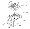
次に、各部材の詳細を図面に基づき説明する。図4及び図5に示す容量式電磁流量計100は、容量式電磁流量計本体を構成する本体ケース110と、表示ユニット50とで構成される。この容量式電磁流量計は、本体ケース110の両端面に開口された流路口111から被検出流体を内部に通過させ、その流量を検出して表示ユニット50に表示する。
Next, the detail of each member is demonstrated based on drawing. A capacitive
本体ケース110には、PPS樹脂等が利用できる。特に本体ケース110を金属でなく樹脂で形成することにより、軽量化を図ると共に複雑な形状にも容易に形成でき、安価に構成できる利点が得られる。本体ケース110の上面には、図5に示すように、表示ユニット50が固定される。また本体ケース110の側面には、図6に示すように測定管10を収納するハウジング120の前後に各々サイドカバー130を固定している。各サイドカバー130には被検出流体を流入、排出するための流路口111を開口している。
PPS resin or the like can be used for the
さらにサイドカバー130の上面はヨーク蓋140で、下面は補強板142で各々閉塞している。さらに補強板142を覆うように、断面コ字状の本体カバー150で被覆し、本体カバー150の両端でサイドカバー130を固定して補強している。本体ケース110を本体カバー150で被覆して、サイドカバー130同士を本体カバー150で固定する状態を図7に示す。この図に示すように、ハウジング120の前後にサイドカバー130を固定した状態で、本体カバー150の側板155を挿入できる段差を形成している。さらに本体カバー150で本体ケース110を被覆した状態で、側板155に開口された螺子孔156に螺子を挿入して、本体カバー150の両端でサイドカバー130を螺号して固定する。さらに螺子孔156は、ハウジング120とサイドカバー130との連結に兼用することもでき、これにより組み立て作業効率も向上される。
Further, the upper surface of the
本体カバー150は、板金等剛性のある部材で構成し、両端でサイドカバー130と螺子で螺号する等して、容量式電磁流量計の筐体に強度を持たせる。これにより、容量式電磁流量計を配管する際に、容量式電磁流量計の両側に設けられた配管固定機構に応力が加えられても、十分対抗できる強度を付与できる。例えば流路口111の内面に設けられた螺子溝112を螺号すると、両端から逆向きのトルクが加えられるが、このような捻れ応力で本体ケース110が破損しないよう本体カバー150が補強する。
The
また、容量式電磁流量計の筐体全体を金属製とするのでなく、本体ケース110を樹脂部材とすることで軽量化も図られる。本体カバー150は金属製ではあるが比較的軽量な板金で構成することにより、全体としての軽量化が実現できる。さらに本体ケース110を複雑な形状としても、金属製の場合と比較して安価に形成でき、コスト面でも有利となる。特に金属部品は単純な板金形状とすることで、安価とできる。さらにまた、容量式電磁流量計の本体ケース110表面を板金等の本体カバー150で被覆することにより、筐体表面を保護する効果も得られる。加えて、両端のサイドカバー130同士を金属製の本体カバー150で連結することにより、両端面を導通させてアース電位を共通にできるという副次的な効果も得られる。一方、本体ケース110には液アース端子144を備えており、被検出流体の電位をサイドカバー130の接地電位とする。
In addition, the entire casing of the capacitive electromagnetic flow meter is not made of metal, but the weight can be reduced by using the
本体カバー150は、上記の例では図8(a)に示すように一枚の断面コ字状本体カバー150でハウジング120全体をカバーする構成とした。特に板金を断面コ字状に折曲することで、曲げ強度を一層増すことができる。また本体カバー150一枚でサイドカバー130同士を連結できるので、部品点数も最小限とでき、組み立て作業性にも優れる。ただ、本体カバーは、上記の構成に限られず、複数枚で構成してもよい。例えば図8(b)に示すように、本体カバー151を2枚、それぞれ断面コ字状とし、これらをハウジング120の上下から覆うように構成することもできる。あるいは図8(c)に示すように、断面L字状の本体カバー152とし、これらをハウジング120の対角線方向から狭持する構成としてもよい。さらに図8(d)に示すように、2枚の平板状本体カバー153を使用して、サイドカバー同士を橋渡しする構成としても良い。
(サイドカバー130)
In the above example, the
(Side cover 130)
サイドカバー130は、流路口111を開口している。流路口111は、本体ケース110に内蔵される測定管10とで流路を構成する。流路の口径は、流路口111の一端から他端までほぼ同じ直径として、この流路に被検出流体を一方向に流す際の損失を低減する。流路口111の部分には、容量式電磁流量計を設置する工場等の外部配管(図示せず)と接続するための配管固定機構として、流路口111の内面に螺子溝112が形成されている。螺合により配管する際の機械的強度を確保するために、好ましくはサイドカバー130を金属で一体に形成する。なお外部配管と流路との他の接続方法としては、本体ケースの開口端面にボルトを植設し、他方、外部配管の端にフランジを設け、このフランジの挿通孔にボルトを通した後にナットを螺着させることによって本体ケースと外部配管とを接続するようにしてもよい。
(測定管10)
The
(Measurement tube 10)
測定管10は、管状の内部に被検出流体を通過させる絶縁性ライニングである。測定管10には、被検出流体を通過させるパイプとしての優れた耐薬品性能と、コンデンサを構成するための電気的特性とが要求される。機械的特性の面からは、測定管10は、被検出流体の圧力、温度変化による配管の伸縮に基づく引張又は圧縮の力を担う強度母体とし、かつそれに耐える所要の内径、肉厚、長さを有する剛構造部材とする。一方、電気的特性の面からは、測定管10は非磁性の絶縁性部材として誘電体材料であることが望まれる。特に測定管10の周囲に貼付される電極30と被検出流体との静電容量結合を高めS/N比を改善するために、誘電率の高い材質で構成する。このような材質としてはセラミックスやプラスチックが利用できる。一般的にはセラミックスが用いられるが、測定管の外周面に、後述する位置決めのための突起12や段差14を一体的に形成する場合、成形時の熱収縮による位置決め精度の低下や、後加工でこのような突起や段差を形成するとコスト的に高くなるおそれがある。このため、本実施の形態では比較的強度があり、且つ成形精度と高誘電性を確保できるセラミックスを混入したPPS樹脂を採用している。PPS樹脂は、耐油、耐薬品性等に優れる。本実施の形態では、ポリプラスチックス株式会社製フレクティス(登録商標)を使用した。また測定管10の内面には必要に応じてライニングが施工される。
The
被検出流体は、水や非腐食性の液体であり、所定の導電率を備える液体である。容量式電磁流量計は、接液式の電磁流量計と異なり、電極30を被検出流体に直接接触させないため、従来は使用できなかった電極を腐食するような液体であっても測定できる。また、測定管10の材質を選択することによって、様々な被検出流体に対応できる。特に、測定精度等に対応して要求される誘電率と、被検出流体に対する耐性に応じて、測定管10の材質を選択できる。特に本実施の形態に係る容量式電磁流量計は、測定管10を本体ケース110と別部材としているので、測定管10のみを変更し、他の構成部品を共通化して様々な仕様の容量式電磁流量計を構成でき、製品仕込みの上で有利なものとなる。
The fluid to be detected is water or a non-corrosive liquid, and is a liquid having a predetermined conductivity. Unlike the liquid contact type electromagnetic flow meter, the capacity type electromagnetic flow meter does not directly contact the
さらに測定管10には、円柱状の測定管10の回転を阻止するための回転阻止機構を設けている。すなわち、測定管10の周囲で電極30と励磁コイル22とを直交させる必要があるため、円柱状の測定管10が回転して位置ずれを生じると、正確な検出に支障を来すおそれがある。このため、図9(a)に示すように測定管10の外周に突起12を設けている。突起12を支承する孔をプリアンプモジュール160や本体ケース110等に形成することで、測定管10を所定の姿勢に位置決めし、回転を阻止する。
Further, the
測定管10は、本体ケース110と別部材とする。これにより、測定管10を構成する部材にはコンデンサに適した材質を選択できる。一方で本体ケース110は、複雑な形状にも容易に成型可能な樹脂が使用できる。このように、測定管10を本体ケース110と別部材とすることにより、各々に適した部材で構成できる。特に測定管を構成する高誘電材料は一般に高価であるため、必要な部分のみを高価な部材で構成し、他の部材はより安価な材質として全体のコストを低減できる。また、容量式電磁流量計に要求される精度等に応じて、適切な材質の測定管10を選定できる。さらに、口径の異なる測定管に交換することもできる。このように、容量式電磁流量計の検出目的や用途、求められる仕様やコストに応じて、適切な材質の測定管を選定することができる。また、複数の測定管を一の容量式電磁流量計にセット可能とすることで、多品種の容量式電磁流量計の部材を共通化して、安価に提供できる。
(電極30)
The
(Electrode 30)
測定管10の周囲には電極30が配置される。電極30は、ポリイミド等の絶縁テープに銅箔をコーティングしたものが使用できる。この電極30は、図9(b)に示すように、円筒状の測定管10の外周に沿うように湾曲された面状の導電体であり、一対の電極30を測定管10を挟んで対向するように配置する。このように一対の電極30と被検出流体との静電結合により、流体中に発生した起電力を測定管10から外部に取り出して、流量を検出できる。各電極30は、測定管10の外周に隙間なく貼付される。貼付にはテープや接着剤等が利用できる。電極30は、好ましくは可撓性部材で構成することにより、測定管10の外面に隙間なく固定できる。
An
また面状の導電体である電極の腐食や結露による一対の電極間の導通を防止するために、導電体は絶縁層で被覆することが好ましい。図9の例では、シリコーン樹脂等の絶縁性の接着材を介して測定管10の外周に接着することにより、絶縁層の形成と接着を同時に実現している。また、その他の構成として絶縁層としてポリイミド樹脂テープを使用し、ポリイミド樹脂テープ上に銅箔の面状導電体を予め設けた電極30を、測定管10上に配置する構成とすることもできる。測定管10の周囲には、電極30を配置する位置及び大きさに段差14を形成しており、電極30の位置決めを実現する。段差14は、測定管10外周の肉厚を薄くすることで形成している。
In order to prevent conduction between the pair of electrodes due to corrosion or condensation of the electrode which is a planar conductor, the conductor is preferably covered with an insulating layer. In the example of FIG. 9, the insulating layer is formed and bonded simultaneously by bonding to the outer periphery of the measuring
さらに電極30は、プリアンプモジュール160と電気接続するためのリードを設ける。図9の例では、銅箔の面状導電体の一部に切り込みを入れてリード片32とし、これを引き出している。この構成は、リードの配線等を不要とし、極めて安価且つ容易に電極30の配線を行うことができる。
Further, the
なおこの例では一対の電極を使用したが、2組以上の電極を使用することも可能である。複数組の電極を使用する場合、各電極で検出する電界が磁界と直交するように、電極の位置は調整される。
(ハウジング120)
Although a pair of electrodes is used in this example, two or more sets of electrodes can be used. When a plurality of sets of electrodes are used, the positions of the electrodes are adjusted so that the electric field detected by each electrode is orthogonal to the magnetic field.
(Housing 120)
次にハウジング120の内部に収納される部材を、図10の分解斜視図に基づいて説明する。この図に示すように、ハウジング120は測定管10と、一対のプリアンプと、励磁モジュール170とを備える。またハウジング120の前後には貫通孔121が開口され、ここに測定管10が挿入される。またハウジング120内部に保持される測定管10の上下に、プリアンプが配置される。図11に示すように、電極30を装着した状態で、測定管10の上下からプリアンプモジュール160にて狭持する。
(プリアンプ)
Next, members housed in the
(Preamplifier)
プリアンプモジュール160は、信号増幅用のプリアンプを構成する。容量式電磁流量計においては、電極30と被検出流体との静電容量結合が一般に数十pF程度と小さいため、電気信号を通すためのフィルタを設ける際の抵抗のインピーダンスが極めて高くなっている。このため、各電極30に検出回路34としてプリアンプを接続してインピーダンスを下げる。図10に示すプリアンプは、測定管10に配置される一対の電極30と電気的に接続され、検出された電気信号を増幅して制御部40に送出する。このプリアンプは、プリアンプモジュール160を、シールドケース161に収納し、さらにシールドカバー162で閉塞し、電極30を含むプリアンプを確実にシールドして電気信号をノイズから保護する。
(プリアンプモジュール160)
The
(Preamplifier module 160)
プリアンプモジュール160の外観を図11に示す。この図において、図11(a)は一対のプリアンプモジュール160の斜視図を、図11(b)はプリアンプモジュール160の分解斜視図を、それぞれ示している。各プリアンプモジュール160は、図11(b)に示すように、プリアンプ基板164と、プリアンプ基板ホルダ165と、電極保護シート166とで構成される。プリアンプ基板164は、電極30で検出された電気信号増幅用の電子部品を実装する。プリアンプ基板164は、プリアンプ基板ホルダ165に保持される。図11(b)に示すプリアンプ基板ホルダ165は、上面にプリアンプ基板164を保持する開口を形成している。またプリアンプ基板ホルダ165は、下面を測定管10の側面に沿うようアーチ状に湾曲させており、この湾曲面に電極保護シート166を固定する。電極保護シート166は、ゴム等の弾性体で構成され、プリアンプ基板ホルダ165の湾曲面で押圧されて、電極30を測定管10の周囲に隙間なく押圧する。特に電極30による静電容量結合を高めるため、電極30と測定管10との間に隙間が生じないように固定する必要がある。この作業を、電極保護シート166を利用することで、プリアンプモジュール160を測定管10にセットする際に、電極30を測定管10の周囲に確実に押圧して隙間なく固定でき、信頼性を高めると共に構成を簡素化して作業能率も向上する。
(励磁モジュール170)
An appearance of the
(Excitation module 170)
さらに、図10に示すハウジング120は、測定管10の左右側面を挟むように、励磁モジュール170が配置される。励磁モジュール170は、励磁コイル22を備えており、測定管10の左右から磁界を付与する。したがって、電極30により検出される電界と磁界が直交するように、励磁モジュール170とプリアンプの配置位置が設定される。
Furthermore, the
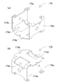
励磁モジュール170の斜視図を図12に示す。図12(a)は励磁モジュール170を斜め上方から見た斜視図、図12(b)は斜め下方から見た斜視図を、それぞれ示している。この図に示す励磁モジュール170は、励磁コイル22を保持するコイルケース172と、コイルケース172を一対、対向するように固定する励磁プレート174と、中継基板176で構成される。
(励磁プレート174)
A perspective view of the
(Excitation plate 174)
励磁プレート174の斜視図を図13(a)、(b)に示す。励磁プレート174は、一対のコイルケース172を離間させて保持し、コイルケース172のポールピース178同士の間で磁界を生じさせる。この励磁プレート174は、ほぼ平行に離間させた対向片174aを、連結片174bの両端で連結した断面ほぼコ字状に形成され、対向片174aに各々コイルケース172を保持して、これらを平行に離間させて保持する。また励磁プレート174の上面の両端部には、ヨーク蓋固定用のヨーク片174cが各々形成される。
A perspective view of the
励磁プレート174は、励磁コイル22で発生される磁界で磁気回路を構成するため、強磁性体材料で構成する。この励磁プレート174は、金属等で一体に形成している。また対向するポールピース178同士の間で磁界が効率よく発生されるように、いいかえるとポールピース178から発される磁束が、下方向の連結片174bに向かう漏れ磁束を低減するため、励磁プレート174の一部を部分的に開口している。特に、連結片174bと対向片174aとの接合部分を大きく開口して開口部174dを形成することにより、磁気回路の短絡を防止する。このような形状の励磁プレート174を使用することで、漏れ磁場を低減し、磁気回路の効率を高めることができる。
(中継基板176)
The
(Relay board 176)
また図12(b)に示すように、励磁プレート174の連結片174bの裏面には、中継基板176が固定される。中継基板176は、励磁コイル22を励磁する励磁回路24として、図3に示す初期励磁電源26、励磁継続電源27、励磁極性切替回路28、定電流回路29を構成する。励磁回路24でポールピース178同士の間で交番磁場を発生させるように、中継基板176には必要な電気回路が実装される。この励磁モジュール170は、商用周波数と異なる周波数で交番磁場を発生させる。好ましくは、励磁周波数は商用周波数よりも高い周波数、例えば75kHzとする。これにより、商用周波数で生じるノイズを回避することができる。
(コイルケース172)
As shown in FIG. 12B, a
(Coil case 172)
コイルケース172は、コアを挿入し、コアの周囲に励磁コイル22を捲回する構成とする。コイルケース172の分解斜視図を図14に示す。この図に示すように、コイルケース172は中空の軸で平板172a、172bを連結した形状とし、平板172a、172b同士の間に励磁コイル22を捲回するコイル捲回空間172cが形成される。一方の平板172aには、コアとしてポールピース178を挿入するポールピース挿入口172dが開口される。またポールピース挿入口172dは中空の軸状とし、コイル捲回空間172cを貫通している。さらに他方の平板172bは矩形状とし、図12(a)に示すように励磁プレート174の対向片174aに固定される。
(ポールピース178)
The
(Pole piece 178)
励磁コイル22はポールピースコア178aの周囲に捲回される。ポールピース178は、ポールピースコア178aをなす鉄芯の一端に矩形状の平板178bを固定し、平板178bを介して磁束が出入りする。ポールピースコア178aには積層鉄心等の導電性の磁性材が好適に使用できる。またポールピースコアを使用しないで、この部分で生じる磁気回路遅れを低減する構成としてもよい。
The
この励磁モジュール170は、内蔵される一対の励磁コイル22を離間して配置し、中継基板176で励磁コイル22を励磁してポールピース178同士の間に磁界を生じさせる。これにより、ポールピース178の間に設置された測定管10に対して、被検出流体として導電率を有する液体を流すと、液体の運動方向と直交する方向に起電力を生じさせる。
In this
なお図1の例では、励磁コイル22を2つ使用し、測定管10の左右に設けているが、コイルを一とすることもできる。例えば図20に示すようにコア178Bの両端で測定管10Bを挟むようにすれば、コア178Bに捲回する励磁コイル22Bを一とできる。この図に示す容量式電磁流量計も、図1等と同様に、励磁回路24Bで励磁コイル22Bを励磁し、測定管10Bを通過する被検出流体により生じる起電力を検出回路34Bが電極30Bで検出し、制御部40Bに送出して表示部51Bにて表示する。
In the example of FIG. 1, two
さらに図5に戻り、容量式電磁流量計は、本体ケース110の上面に、表示ユニット50を固定している。本体ケース110の上面には、表示ユニット50を固定するための螺子孔122をハウジング120の四隅に形成している。また、サイドカバー130の上端は、本体ケース110上面に固定された表示ユニット50の表面と同一平面となるよう、窪ませた段差空間が形成されている。この段差空間は、表示ユニット50の外形及び大きさとほぼ等しいか、これよりも若干大きく形成される。
(表示ユニット50)
Further, returning to FIG. 5, the capacitive electromagnetic flow meter has the
(Display unit 50)
表示ユニット50は被検出流体の流量等の情報を表示するための部材であり、図4等に示すように表示部51として表示画面52を備える。図4の例では表示画面52に数値を表示する数値表示領域として、7セグメント式表示器を使用しており、流量等を数値で表示する。7セグメント式表示器には、検出した流量について、瞬時流量や積算流量等の数値を表示する。この図に示す表示画面52は、7セグメント式表示器を2段備えており、積算流量と設定値とを同時に表示可能としている。ただ、7セグメント式表示器を1画面のみ設けて、積算流量や瞬時流量、設定値等の表示を切り替え可能とすることも可能であることはいうまでもない。
The
また表示画面52は、被検出流体の流速や流れ方向を示す流体表示灯53を備える。流体表示灯53は、バー状に配置されたLEDで構成される。流体表示灯53は、例えば流量に応じた速さでLEDを流れ方向に順次点灯させ、流速と流れ方向を感覚的に表現できる。またバー状LEDに代わって、矢印形の表示灯等も利用できる。さらに、LED等を使用したセグメント式の表示画面52に代わって、液晶や有機EL等を使用した表示画面とすることも可能である。このように表示画面52には、流量等の数値のみならず矢印等の図形やイメージを併せて、あるいは択一的に表示させることができ、検出した流量等の情報をユーザに視認しやすい形で表示できる。
The
また表示ユニット50は、各種の設定を行う設定部80として操作パネル54を備えている。操作パネル54は、各種の設定を行うためのキーやボタンを備えている。図4等の例では、表示画面52に4桁の7セグメント式表示器を2段に配置し、さらに右下に操作パネル54を設け、十字方向にキーを配置している。この設定部80は、後述する積算流量の初期値や所定のリセット値を設定するためのリセット設定部等として機能する。
The
なお、この例では表示画面52を表示する表示回路に、検出回路34及び励磁回路24と接続されてこれらを制御する制御部40を組み込んでいる。ただ、制御回路を個別の部材で構成し、本体ケース110内に組み込むことも可能であることは言うまでもない。また制御回路や検出回路、励磁回路等を統合することも可能である。
(出力部60)
In this example, the display circuit that displays the
(Output unit 60)
また、この表示ユニット50は出力部60を備えている。この例では、出力部60は制御出力、アナログ出力、タイムアウト出力を備え、各々の出力に応じた外部出力端子を備えている。制御出力は、容量式電磁流量計で外部機器のON/OFF動作を直接制御するON/OFF出力として使用できる。この場合は、検出された瞬時流量が所定値に達したときにON/OFF出力を切り替えるように、HIGH/LOWの2つの状態に出力するスイッチとして機能する。スイッチ機能は、ノーマルオープン、ノーマルクローズのいずれとしてもよい。あるいは、制御出力として、検出された積算流量に応じたパルス電圧を出力することもできる。この場合は、外部の電圧入力機器に対して、積算流量で制御する用途等に利用できる。また、積算流量をリセットするリセット信号入力端子を備えてもよい。
Further, the
一方、アナログ出力は、測定された瞬時流量や積算流量等に応じたアナログ電流を出力できる。この例では、瞬時流量が0〜定格値の範囲で変化すると、4〜20mAの範囲でアナログ電流を出力する。このため出力部は、アナログ電流出力回路を備える。アナログ電流は電圧信号に比べてノイズ耐性に優れており、これを外部に出力することで、データの記録や解析に利用できる。さらにタイムアウト出力は、後述するようにタイムアウト時にタイムアウト信号を出力する。 On the other hand, the analog output can output an analog current according to the measured instantaneous flow rate or integrated flow rate. In this example, when the instantaneous flow rate changes in the range of 0 to the rated value, an analog current is output in the range of 4 to 20 mA. Therefore, the output unit includes an analog current output circuit. The analog current has better noise immunity than the voltage signal, and can be used for data recording and analysis by outputting it to the outside. Further, the timeout output outputs a timeout signal at the time of timeout as will be described later.
このように出力部60は積算値出力部や瞬時値出力部として機能できる。なお出力部は、上記の制御出力、アナログ出力、タイムアウト出力のいずれかを省略したり、あるいはさらに別の出力端子を備えてもよい。さらに、各出力端子の出力状態を示す出力表示灯を設けてもよい。
(入力部70)
Thus, the
(Input unit 70)
さらに表示ユニット50は入力部70を備えることもできる。入力部70は、温度センサ等の外部機器からの入力信号や、積算値をリセットするためのリセット信号、各種設定情報等を入力するためのインターフェースである。入力部としては、データ通信可能な通信ユニットやI/O端子、メモリカード等が利用できる。
(積算流量)
Further, the
(Integrated flow rate)
この表示画面52には、検出した流量の積算値を順次加算して得られる積算流量をそのまま表示する他、所定の値から積算値を減算した減算値を表示することもできる。これら、積算値を表示する積算値表示モードと、減算値を表示する減算値表示モードとを切り替えて、表示画面52に表示可能としている。
On this
積算値表示モードにおいては、図21に示すように、時間の経過と共に増加する積算流量をリアルタイムで表示する。このため制御部40は、流量演算値で演算された瞬時流量を加算あるいは積算して積算流量を保持するためのメモリ部42を備えている。新たに測定された瞬時流量を順次積算流量に加算することで積算流量を更新し、更新された積算値をメモリ部42に随時保持する。
In the integrated value display mode, as shown in FIG. 21, the integrated flow rate that increases with the passage of time is displayed in real time. For this reason, the
一方、積算のリセット信号がリセット信号入力部から入力されると、積算値をリセットして0とし、新たに積算流量のカウントを開始する。なおリセット信号は、外部機器から入力部を介して入力する場合の他、ユーザが設定部を操作する等して強制的にリセットさせる場合や、一定時間経過後や積算値が所定値に達したとき等、所定の条件に至った際に自律的にリセット信号を生成する場合等がある。またいずれの場合も、リセット信号は反転出力としてもよい。
(減算値表示機能)
On the other hand, when the integration reset signal is input from the reset signal input unit, the integration value is reset to 0, and counting of the integrated flow is newly started. The reset signal may be input from an external device via the input unit, or may be forcibly reset by the user operating the setting unit, or after a certain time has elapsed or the integrated value has reached a predetermined value. Sometimes, a reset signal is generated autonomously when a predetermined condition is reached. In either case, the reset signal may be an inverted output.
(Subtraction value display function)
一方、減算値表示モードにおいては、積算流量を所定値から減算した値を表示画面52に表示する。例えば図22に示すように、所定の初期値Aから、積算流量を減算して得られた減算値が時間と共に減少する様子をリアルタイムで表示画面52に表示できる。また減算値は、所定のタイミングで積算リセット信号がリセット信号入力部から入力されると、初期値Aにリセットされて、再び初期値Aからの減算が再開される。積算流量の初期値は、設定部80からユーザが指定可能とできる。これによってユーザは使用目的に応じた所望の値を設定することが可能となり、積算値のみならず減算値の表示を可能としたことと組み合わせて、従来よりも直感的で判り易い流量表示を実現できる。
On the other hand, in the subtraction value display mode, a value obtained by subtracting the integrated flow rate from a predetermined value is displayed on the
例えば、貯水タンクに蓄えられている液体の残量を表示する用途を図23に示す。この例では、排水パイプ820に容量式電磁流量計100を配管して流量を測定し、表示画面52に貯水タンク810内の残量を表示できる。すなわち、貯水タンク810が満水の状態を初期値として、積算流量を減算した値を表示画面52に表示することで、貯水タンク810内に残っている利用可能な水量を数値で直読可能とできる。
For example, FIG. 23 shows an application for displaying the remaining amount of liquid stored in a water storage tank. In this example, the capacity type
同様に、図24に示すような瓶830に液体を充填する用途において、あとどのくらいの量を充填すればよいかを容量式電磁流量計100の表示画面に表示させることもできる。この場合は、瓶1本に充填すべき量を初期値として設定し、充填する液体の積算流量で減算表示すれば、残りの必要な液量を直接表示画面52に表示することができる。
Similarly, in an application in which a
従来の流量センサでは、このようなカウントダウン式の表示を流量センサ単体で行うことができず、ユーザが積算流量を元に自分で計算するか、あるいは流量センサの出力をPLCに入力する等して、残容量を演算するためのプログラムを組む必要があった。これに対し、本実施の形態では、ユーザが容量式電磁流量計の設定部を操作し、積算値の初期値と、減算値の表示を設定するのみで、所望の残量表示が実現できる。このように、流量センサ単体で柔軟な表示を可能とできるので、安価に且つ容易に、用途に応じた適切な表示を実現でき、流量センサの使い勝手を飛躍的に改善できる。
(タイムアウト機能)
In a conventional flow sensor, such a countdown type display cannot be performed by a single flow sensor, and the user calculates it based on the integrated flow or inputs the output of the flow sensor to the PLC. It was necessary to build a program to calculate the remaining capacity. On the other hand, in the present embodiment, the user can operate the setting unit of the capacitive electromagnetic flow meter, and the desired remaining amount display can be realized only by setting the initial value of the integrated value and the display of the subtraction value. As described above, since a flexible display can be performed with a single flow sensor, an appropriate display according to the application can be realized inexpensively and easily, and the usability of the flow sensor can be dramatically improved.
(Timeout function)
一方、この容量式電磁流量計は、ユーザが指定した時間内に積算値出力が出力されない場合に、タイムアウト出力を出力するタイムアウト機能を備える。タイムアウト機能を実行するタイムアウト動作モードでの表示値の変化と入出力状態を、図25に基づいて説明する。ここでは、図22と同様に減算値表示を行っており、減算値が所定の値になると、所定の積算値出力が積算値出力部から出力される。図25の例では、減算値がB以上のときHIGH、B以下のときLOWとなるよう設定されている。そして出力がLOWからHIGHに変化したことを検出して、積算リセット信号がリセット信号入力部から入力されて、積算流量は初期値Cにリセットされる。この例において、何らかの理由で減算値が長時間経過してもB以下に達しない場合は、異常が発生したと判断できる。そこで、一定のタイムアウト時間を予め設定しておき、積算リセット信号が入力された後、制御部40のタイマで計時を開始し、タイムアウト時間が経過するまでの間に再度積算リセット信号の入力が無い場合は、異常と判断してタイムアウト出力をタイムアウト出力部から出力するように構成している。
On the other hand, this capacitive electromagnetic flow meter has a time-out function that outputs a time-out output when the integrated value output is not output within the time specified by the user. The change in display value and the input / output state in the timeout operation mode for executing the timeout function will be described with reference to FIG. Here, the subtraction value is displayed in the same manner as in FIG. 22, and when the subtraction value reaches a predetermined value, a predetermined integrated value output is output from the integrated value output unit. In the example of FIG. 25, it is set to be HIGH when the subtraction value is B or more, and LOW when the subtraction value is B or less. Then, when it detects that the output has changed from LOW to HIGH, an integrated reset signal is input from the reset signal input unit, and the integrated flow rate is reset to the initial value C. In this example, if the subtraction value does not reach B or less for a long time for some reason, it can be determined that an abnormality has occurred. Therefore, a predetermined timeout time is set in advance, and after the integration reset signal is input, the timer of the
例えば、上述した図24の瓶830への液体充填の例において、充填すべき液量と充填速度が予め判明している場合は、充填作業に必要な所要時間も予測できる。よって、この予測時間に基づいてタイムアウト時間を設定し、かつ減算値が所定値(例えば0)に達したときは積算リセット信号が入力されるよう設定しておくことにより、このタイムアウト時間が経過しても減算値が所定値に達しない場合は、充填が完了しない何らかの異常が発生したと考えられる。そこでタイムアウト出力部を異常出力と設定しておけば、タイムアウト出力を検出することで、システムの異常を検出できるようになる。例えば、図24のように瓶に液を充填する用途においては、瓶が破損して液漏れしている、充填液が空になっている、パイプ詰まりを起こしている等の異常を、流量センサ単体で検出できる。このように、流量センサ単体で検出を可能とし、判別システムを簡素且つ安価に構築できるという利点も得られる。特に従来の流量センサは単体ではこのような検出ができなかったが、本実施の形態に係る流量センサは、積算流量を利用した減算値表示を可能とすると共に、タイムアウト時間を設定する機能を持たせることにより、単なる数値表示以上の判別機能をも実現できるようになり、流量センサの用途を拡大できる。なお、タイムアウト機能については、減算値すなわちダウンカウントのみならず、積算流量すなわちアップカウントを利用することも可能であることはいうまでもない。例えば、初期値からどれだけ充填液が供給されたかを知りたい用途において、積算流量が所定値に達したときにリセット信号が入力されるよう設定して利用できる。
(表示ユニット50)
For example, in the above-described example of filling the
(Display unit 50)
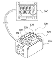
一方、表示ユニット50としては、本体ケース110に表示ユニット50を設ける一体型表示ユニット50と、本体ケース110とは別の位置に表示ユニットを配置する分離型表示ユニット50Bとが利用できる。図15に、一体型表示ユニット50の分解斜視図を示す。
(一体型表示ユニット50)
On the other hand, as the
(Integrated display unit 50)
この図に示す一体型表示ユニット50は、フロントケース55と、電源ケーブル56と、表示基板57と、電源基板58とを備える。フロントケース55は、表示ユニット50の筐体であり、表示基板57を内部に保持すると共に、開口窓を通じて表示基板57上に設けられた7セグメント式表示器が外部に表出するように位置決めして固定する。また表示基板57の裏面には電源基板58が離間して配置される。電源ケーブル56は、容量式電磁流量計を駆動するための外部電源と接続されて、容量式電磁流量計に電力を供給する。表示基板57は、7セグメント式表示器や各種インジケータを構成するLED等の表示素子の駆動回路や、操作パネル54のスイッチ等を含む電子部品やCPU等の制御部品が実装されている。さらに、表示基板57と別に電源基板58が用意され、電源回路部品が電源基板58に実装される。表示用駆動回路を実装した表示基板57と、電源回路を実装した電源基板58とを分離することにより、電源回路の発熱を表示回路の電子部品から分離できる。
(択一固定機構)
The
(Alternative fixing mechanism)
表示ユニット50は、容量式電磁流量計の取り付け位置や姿勢に応じて、ユーザが表示画面52を目視しやすい姿勢に表示ユニット50の取り付け方向を変更可能としている。図16に、容量式電磁流量計の本体ケース110に、表示ユニット50を固定する様子を示す。図16(a)は、分離型表示ユニット50B、図16(b)は一体型表示ユニット50を固定する状態、非検出流体の流れ方向と水平に固定する状態、図16(c)は図16(b)と同じ一体型表示ユニット50を、非検出流体の流れ方向と垂直な姿勢に固定する状態を、それぞれ示している。
The
具体的には、表示ユニット50及び本体ケース110上面の段差空間をほぼ正方形状として、表示ユニット50の取り付け角度を90°回転させても、固定可能としている。このため、表示ユニット50を本体ケース110上面に固定するための螺子孔122は、正確に四隅に穿孔されている。これにより、表示ユニット50を90°回転させた姿勢でも本体ケース110に固定でき、表示画面52の表示方向を変更できる。すなわち、被検出流体の流れ方向(例えば上下又は左右)に沿う姿勢に測定管10を固定すると共に、この容量式電磁流量計に固定する表示ユニット50の姿勢は、ユーザが表示画面52を目視しやすい方向に固定できる。
Specifically, the step space on the upper surface of the
従来、容量式電磁流量計を配管等に固定する際、容量式電磁流量計が横置きの姿勢のみならず、縦置きの姿勢で固定されることもあった。この場合、表示器が縦方向に配置されるため、横書きで表示される数値が読みづらくなるという問題があった。一方、上述した特許文献2に示すように、縦横いずれの方向でも表示画面52を視認できるよう、表示ユニット50を本体ケース110と回転させる機構を備えた流量計も存在したが、回転機構が必要となり、その分構造が複雑となり、コストアップやサイズの大型化等の問題があった。これに対し、上記の構成では、取り付け姿勢を変更してねじ止めするという極めて簡単な構成であるため、部品点数が増えることもなく、小型化を実現しつつ、表示画面52が水平となるように、すなわちユーザが直立した姿勢から目視できる姿勢に、固定することができ、視認性がよくなる。
Conventionally, when a capacitive electromagnetic flow meter is fixed to a pipe or the like, the capacitive electromagnetic flow meter is sometimes fixed not only in a horizontal posture but also in a vertical posture. In this case, since the display device is arranged in the vertical direction, there is a problem that it is difficult to read numerical values displayed in horizontal writing. On the other hand, as shown in Patent Document 2 described above, there has been a flow meter provided with a mechanism for rotating the
なお、表示ユニット50を固定する方法は四隅の螺合に限られず、例えば正方形の各辺の中間に螺子孔を穿孔したり、フック等による係合や嵌合とすることもできる。
Note that the method of fixing the
また、必ずしも一の表示ユニットの取り付け角度を変更する構成に限られず、例えば水平方向表示用の表示ユニット、垂直方向表示用の表示ユニットを個別に用意し、用途に応じて適切な表示ユニットを選択して固定するように構成してもよい。この構成であれば90°回転可能な構成とする必要がないので、本体ケースの上面形状をほぼ正方形状とする必要がなく、本体ケースの形状を長方形状等様々な形状とすることができる利点が得られる。 In addition, it is not necessarily limited to the configuration in which the mounting angle of one display unit is changed. For example, a display unit for horizontal display and a display unit for vertical display are prepared separately, and an appropriate display unit is selected according to the application. And may be configured to be fixed. This configuration eliminates the need for a 90 ° rotatable configuration, so there is no need to make the upper surface of the main body case substantially square, and the main body case can have various shapes such as a rectangular shape. Is obtained.
さらに、本体ケース110に固定する表示ユニット50を交換式とできる。これにより、本体ケース110は一体型、分離型のいずれの表示ユニット50に対しても共通に使用でき、部材の共通化を図れるという利点が得られる。
(分離型表示ユニット50B)
Furthermore, the
(
図16(a)は、分離型の表示ユニット50Bの一例を示している。分離型表示ユニット50Bは、図17に示すように表示画面52を本体ケース110から離間させて、本体ケース110には表示パネル50Cを配置し、ケーブル等により電気信号をやりとりして、本体ケース110と離れた位置で流量等の情報を表示画面52に表示する。表示パネル50Cは、上述した一体型表示ユニット50と同様の構成とできる。
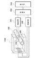
FIG. 16A shows an example of a
図18に、分離型表示ユニットを使用した電磁流量計200のブロック図を示す。この図に示す電磁流量計200は、本体ケースについては、上述した図3に係る一体型表示ユニットを使用した電磁流量計の本体ケース110と同じものが使用でき、詳細説明は省略する。図18のブロック図では、表示ユニット50Bに、A/D変換器38Bと、制御部40Cと、表示部として動作表示画面52Bと、出力部としてアナログ電流出力回路62Bと、通信部としてシリアル通信回路63を備える。シリアル通信回路63は、表示パネル50Cとデータ通信を行い、表示パネル50Cで表示すべき必要なデータを送信する。
FIG. 18 shows a block diagram of an
図16(a)の例では、7セグメント式表示器に代わって、本体ケース110の上面に動作表示画面52Bとして、被検出流体の通過を示すインジケータ53Bを設けている。動作表示画面52Bは、流量を検出中であること等、容量式電磁流量計の動作状態を示す他、被検出流体の移動方向を示すことができる。図16(a)の例ではインジケータ53Bとして、測定管10の検出方向に沿って矢印状の表示灯を4つ水平に並べており、LED等によって表示灯を点灯させる。インジケータ53Bは、被検出流体の通過方向に向かってインジケータ53Bを点滅させ、光を移動させるように点灯させることによって流れ方向を視覚的に表示する。
In the example of FIG. 16A, an
例えば、検出方向に沿って被検出流体が流れている場合は表示灯を青色に点灯させ、一方被検出流体が逆方向に流れている場合は赤色に表示させる。また、表示灯の点滅パターンを動的に変化させて被検出流体の移動方向を表示させることで、さらに視覚的に流体の移動を容易に認識することができる。 For example, when the fluid to be detected is flowing along the detection direction, the indicator lamp is lit in blue, while when the fluid to be detected is flowing in the reverse direction, it is displayed in red. Further, by dynamically changing the blinking pattern of the indicator lamp to display the movement direction of the fluid to be detected, the movement of the fluid can be more easily recognized visually.
分離型表示ユニット50Bを構成する動作表示画面52Bの分解斜視図を図19に示す。この図に示す分離型表示ユニット50Bは、フロントケース55Bと、表示基板57Bと、電源基板58Bと、電源ケーブル56Bと、温度センサケーブル59Bとを備える。フロントケース55Bは、インジケータ53Bをインサート成形している。表示基板57Bや電源基板58Bは、上述した一体型表示ユニット50と同様の部品を実装して構成できる。さらにこの例では、被検出流体の温度を検出する温度センサからの入力信号を温度センサケーブル59Bを介して入力部70に入力し、被検出流体の温度を、離間して配置した表示パネル50C側に送出して表示させることもできる。
FIG. 19 shows an exploded perspective view of the
なお、本体ケース上面の動作表示画面からインジケータを省いたり、逆に分離型表示ユニットであっても本体ケース側に流量等を表示する表示画面を設けること、すなわち表示ユニットを本体ケースと、それ以外の位置の2カ所に設けることも可能であることは言うまでもない。 In addition, omitting the indicator from the operation display screen on the top surface of the main body case, or conversely providing a display screen for displaying the flow rate etc. on the main body case side even if it is a separate display unit. Needless to say, it can also be provided at two positions.
以上のように、本発明によればユーザの用途に応じた表示機能を提供でき、ユーザの利便性を飛躍的に高めた流量センサを実現できる。なお上記では流量センサとして容量式電磁流量計に適用した例を説明したが、これに限られず接液式の電磁流量計やその他の流量検出手段を備える流量センサ、例えばタービン式、カルマン渦式、ダイヤフラム式、パドル式、超音波式等、様々な既知のセンサを適宜採用することができる。 As described above, according to the present invention, it is possible to provide a display function according to a user's application, and to realize a flow rate sensor that greatly improves user convenience. In addition, although the example applied to the capacity | capacitance type electromagnetic flowmeter as a flow sensor was demonstrated above, it is not restricted to this, A flow sensor provided with a liquid contact type electromagnetic flowmeter and other flow detection means, for example, a turbine type, a Karman vortex type, Various known sensors such as a diaphragm type, a paddle type, and an ultrasonic type can be appropriately employed.
本発明の流量センサは、導電性液体の流量を検出する容量式電磁流量計として、例えばダイカスト金型の冷却水管理、バルブの開け忘れチェック、冷却水の使用量チェック等の用途に好適に適用できる。また電磁流量計に限られず、例えば流れの中に配置された渦発生柱の下流に規則的に発生するカルマン渦を超音波により非接触で検出する音波渦流流量センサ等に対しても適用できる。さらに、液体に限られず気体の流量を検出する流量センサにも適用できる。 The flow sensor of the present invention is suitably applied to applications such as a die-casting mold cooling water management, forgetting to open a valve, and a cooling water usage check as a capacitive electromagnetic flow meter for detecting the flow rate of a conductive liquid. it can. Further, the present invention is not limited to an electromagnetic flow meter, and can be applied to, for example, a sonic vortex flow sensor that detects Karman vortices regularly generated downstream of a vortex generating column disposed in a flow in a non-contact manner using ultrasonic waves. Furthermore, the present invention can be applied to a flow rate sensor that detects the flow rate of gas without being limited to liquid.
100、200…電磁流量計
10、10B…測定管
12…突起
14…段差
22、22B…励磁コイル
24、24B…励磁回路
25…励磁電源
26…初期励磁電源
27…励磁継続電源回路
28…励磁極性切替回路
29…定電流回路
30、30B…電極
32…リード片
34、34B…検出回路
35…差動増幅器
36…増幅器
37…周期性リセット回路
38、38B…A/D変換器
40、40B、40C…制御部
42…メモリ部
50…表示ユニット
50B…分離型表示ユニット
50C…表示パネル
51、51B…表示部
52…表示画面
52B…動作表示画面
53…流体表示灯
53B…インジケータ
54…操作パネル
55、55B…フロントケース
56、56B…電源ケーブル
57、57B…表示基板
58、58B…電源基板
59B…温度センサケーブル
60…出力部
61…外部出力回路
62、62B…アナログ電流出力回路
63…シリアル通信回路
70…入力部
80…設定部
110…本体ケース
111…流路口
112…螺子溝
120…ハウジング
121…貫通孔
122…螺子孔
130…サイドカバー
140…ヨーク蓋
142…補強板
144…液アース端子
150、151、152、153…本体カバー
155…側板
156…螺子孔
160…プリアンプモジュール
161…シールドケース
162…シールドカバー
163…プリアンプ
164…プリアンプ基板
165…プリアンプ基板ホルダ
166…電極保護シート
170…励磁モジュール
172…コイルケース
172a、172b…平板
172c…コイル捲回空間
172d…ポールピース挿入口
174…励磁プレート
174a…対向片
174b…連結片
174c…ヨーク片
174d…開口部
176…中継基板
178…ポールピース
178a…ポールピースコア
178b…平板
178B…コア
800…流量計
810…貯水タンク
820…排水パイプ
830…瓶
900…接液式電磁流量計
901…流量検出手段
902…交流増幅器
903…電極
904…同期整流回路
905…タイミングパルス発生回路
906…A/D変換器
940…制御部
908…出力部
910…交流電源
911…測定管
922…励磁コイル
924…励磁回路
951…表示部
DESCRIPTION OF
Claims (6)
本体ケースと、
前記本体ケース内に配設されて、被検出流体を通過させるための管状の測定管と、
前記測定管を流れる被検出流体の流量を検出可能な流量検出手段と、
前記流量検出手段で検出された被検出流体の流量に基づき、積算流量を演算可能な流量演算部と、
前記流量演算部で演算された積算流量を表示可能な表示部と、
前記流量演算値で演算された積算流量を保持するためのメモリ部と、
リセット信号を受信すると、前記メモリ部に保持された積算流量を所定のリセット値にリセットするリセット信号入力部と、
前記所定のリセット値を設定するためのリセット設定部と、
を備え、
予め設定された所定値から積算流量を減算した減算値を、前記表示部に表示可能に構成してなることを特徴とする流量センサ。 A flow sensor for detecting a flow rate of a fluid to be detected,
A body case,
A tubular measuring tube disposed in the main body case for passing a fluid to be detected;
Flow rate detection means capable of detecting the flow rate of the fluid to be detected flowing through the measurement tube;
A flow rate calculation unit capable of calculating an integrated flow rate based on the flow rate of the fluid to be detected detected by the flow rate detection means;
A display unit capable of displaying the integrated flow rate calculated by the flow rate calculation unit;
A memory unit for holding the integrated flow rate calculated by the flow rate calculation value;
When a reset signal is received, a reset signal input unit that resets the integrated flow rate held in the memory unit to a predetermined reset value;
A reset setting unit for setting the predetermined reset value;
With
A flow rate sensor configured to display a subtracted value obtained by subtracting the integrated flow rate from a predetermined value set in advance on the display unit.
前記リセット信号が、外部入力若しくはユーザの指定により入力可能に構成されてなることを特徴とする流量センサ。 The flow sensor according to claim 1,
The flow rate sensor is configured so that the reset signal can be input by an external input or a user designation.
前記流量演算値で演算された積算流量を、前記所定のリセット値から減算した減算値を、前記表示部に表示可能に構成してなることを特徴とする流量センサ。 The flow sensor according to claim 1 or 2,
A flow rate sensor configured to be able to display a subtracted value obtained by subtracting the integrated flow rate calculated from the flow rate calculated value from the predetermined reset value on the display unit.
本体ケースと、
前記本体ケース内に配設されて、被検出流体を通過させるための管状の測定管と、
前記測定管を流れる被検出流体の流量を検出可能な流量検出手段と、
前記流量検出手段で検出された被検出流体の流量に基づき、積算流量を演算可能な流量演算部と、
前記積算流量が所定値に達した際に所定の積算値出力を変更可能な積算値出力部と、
予め設定された所定の時間内に前記積算値出力部が積算値出力を変更しない場合に、所定のタイムアウト出力を出力可能なタイムアウト出力部と、
を備えることを特徴とする流量センサ。 A flow sensor for detecting a flow rate of a fluid to be detected,
A body case,
A tubular measuring tube disposed in the main body case for passing a fluid to be detected;
Flow rate detection means capable of detecting the flow rate of the fluid to be detected flowing through the measurement tube;
A flow rate calculation unit capable of calculating an integrated flow rate based on the flow rate of the fluid to be detected detected by the flow rate detection means;
An integrated value output unit capable of changing a predetermined integrated value output when the integrated flow rate reaches a predetermined value;
A timeout output unit capable of outputting a predetermined timeout output when the integrated value output unit does not change the integrated value output within a predetermined time set in advance;
A flow sensor comprising:
本体ケースと、
前記本体ケース内に配設されて、被検出流体を通過させるための管状の測定管と、
前記測定管を流れる被検出流体の流量を検出可能な流量検出手段と、
前記流量検出手段で検出された被検出流体の流量に基づき、積算流量を演算可能な流量演算部と、
予め設定された所定値から積算流量を減算した減算値を表示可能な表示部と、
前記積算流量が所定値に達した際に所定の積算値出力を出力可能な積算値出力部と、
予め設定された所定の時間内に前記積算値出力部が積算値出力を出力しない場合に、所定のタイムアウト出力を出力可能なタイムアウト出力部と、
を備えることを特徴とする流量センサ。 A flow sensor for detecting a flow rate of a fluid to be detected,
A body case,
A tubular measuring tube disposed in the main body case for passing a fluid to be detected;
Flow rate detection means capable of detecting the flow rate of the fluid to be detected flowing through the measurement tube;
A flow rate calculation unit capable of calculating an integrated flow rate based on the flow rate of the fluid to be detected detected by the flow rate detection means;
A display unit capable of displaying a subtraction value obtained by subtracting the integrated flow rate from a predetermined value set in advance;
An integrated value output unit capable of outputting a predetermined integrated value output when the integrated flow rate reaches a predetermined value;
A timeout output unit capable of outputting a predetermined timeout output when the integrated value output unit does not output an integrated value output within a predetermined time set in advance;
A flow sensor comprising:
前記流量検出手段が、
被検出流体に交番磁場を印加するための磁場印加手段と、
被検出流体と非接触となるよう前記測定管と結合される電極と、
前記測定管を通過する被検出流体の流量を演算する演算手段と、
を備えることを特徴とする流量センサ。 The flow sensor according to any one of claims 1 to 5,
The flow rate detecting means is
Magnetic field application means for applying an alternating magnetic field to the fluid to be detected;
An electrode coupled to the measuring tube so as to be in non-contact with the fluid to be detected;
A computing means for computing the flow rate of the fluid to be detected passing through the measuring tube;
A flow sensor comprising:
Priority Applications (1)
| Application Number | Priority Date | Filing Date | Title |
|---|---|---|---|
| JP2006126763A JP2007298400A (en) | 2006-04-28 | 2006-04-28 | Flow sensor |
Applications Claiming Priority (1)
| Application Number | Priority Date | Filing Date | Title |
|---|---|---|---|
| JP2006126763A JP2007298400A (en) | 2006-04-28 | 2006-04-28 | Flow sensor |
Publications (2)
| Publication Number | Publication Date |
|---|---|
| JP2007298400A true JP2007298400A (en) | 2007-11-15 |
| JP2007298400A5 JP2007298400A5 (en) | 2009-05-21 |
Family
ID=38768009
Family Applications (1)
| Application Number | Title | Priority Date | Filing Date |
|---|---|---|---|
| JP2006126763A Pending JP2007298400A (en) | 2006-04-28 | 2006-04-28 | Flow sensor |
Country Status (1)
| Country | Link |
|---|---|
| JP (1) | JP2007298400A (en) |
Cited By (5)
| Publication number | Priority date | Publication date | Assignee | Title |
|---|---|---|---|---|
| JP2011013198A (en) * | 2009-07-06 | 2011-01-20 | Keyence Corp | Coriolis mass flow meter |
| JP2011058950A (en) * | 2009-09-09 | 2011-03-24 | Keyence Corp | Coriolis mass flowmeter and correction method of the same |
| JP2016109605A (en) * | 2014-12-09 | 2016-06-20 | アズビル株式会社 | Integration device and pulse output pace display method |
| US10323973B2 (en) | 2017-08-28 | 2019-06-18 | Semiconductor Components Industries, Llc | Capacitive sensor for liquid sensing |
| CN111984038A (en) * | 2019-05-23 | 2020-11-24 | 佛山市顺德区美的电热电器制造有限公司 | Hot water treatment device and water yield control method and device thereof |
Citations (6)
| Publication number | Priority date | Publication date | Assignee | Title |
|---|---|---|---|---|
| JPH0419499A (en) * | 1990-05-14 | 1992-01-23 | Oki Electric Ind Co Ltd | Remainder monitoring device |
| JPH08189853A (en) * | 1995-01-10 | 1996-07-23 | Tokyo Gas Co Ltd | Gas meter |
| JP2001183212A (en) * | 1999-12-28 | 2001-07-06 | Nitto Seiko Co Ltd | Method of external pulse signal output for flow meter |
| JP2003027546A (en) * | 2001-07-11 | 2003-01-29 | Inax Corp | Fixed volume water supply device |
| JP2003126256A (en) * | 2001-10-24 | 2003-05-07 | Yazaki Corp | Portable oxygen bombe having emergency warning function |
| JP2005347040A (en) * | 2004-06-01 | 2005-12-15 | Dainippon Printing Co Ltd | Fuel tank for replacement and fuel cell system |
-
2006
- 2006-04-28 JP JP2006126763A patent/JP2007298400A/en active Pending
Patent Citations (6)
| Publication number | Priority date | Publication date | Assignee | Title |
|---|---|---|---|---|
| JPH0419499A (en) * | 1990-05-14 | 1992-01-23 | Oki Electric Ind Co Ltd | Remainder monitoring device |
| JPH08189853A (en) * | 1995-01-10 | 1996-07-23 | Tokyo Gas Co Ltd | Gas meter |
| JP2001183212A (en) * | 1999-12-28 | 2001-07-06 | Nitto Seiko Co Ltd | Method of external pulse signal output for flow meter |
| JP2003027546A (en) * | 2001-07-11 | 2003-01-29 | Inax Corp | Fixed volume water supply device |
| JP2003126256A (en) * | 2001-10-24 | 2003-05-07 | Yazaki Corp | Portable oxygen bombe having emergency warning function |
| JP2005347040A (en) * | 2004-06-01 | 2005-12-15 | Dainippon Printing Co Ltd | Fuel tank for replacement and fuel cell system |
Cited By (5)
| Publication number | Priority date | Publication date | Assignee | Title |
|---|---|---|---|---|
| JP2011013198A (en) * | 2009-07-06 | 2011-01-20 | Keyence Corp | Coriolis mass flow meter |
| JP2011058950A (en) * | 2009-09-09 | 2011-03-24 | Keyence Corp | Coriolis mass flowmeter and correction method of the same |
| JP2016109605A (en) * | 2014-12-09 | 2016-06-20 | アズビル株式会社 | Integration device and pulse output pace display method |
| US10323973B2 (en) | 2017-08-28 | 2019-06-18 | Semiconductor Components Industries, Llc | Capacitive sensor for liquid sensing |
| CN111984038A (en) * | 2019-05-23 | 2020-11-24 | 佛山市顺德区美的电热电器制造有限公司 | Hot water treatment device and water yield control method and device thereof |
Similar Documents
| Publication | Publication Date | Title |
|---|---|---|
| JP5065620B2 (en) | Electromagnetic flow meter | |
| JP4919702B2 (en) | Sensor device and sensor system | |
| CN107923776B (en) | Electromagnetic flow sensor | |
| US8448524B2 (en) | Magnetic inductive flow meter | |
| JP2007298402A (en) | Capacitive electromagnetic flowmeter | |
| JP2007298400A (en) | Flow sensor | |
| EP2901106A1 (en) | Magnetic flowmeter | |
| JP5102463B2 (en) | Flow sensor | |
| JP2007315812A (en) | Flow sensor | |
| CN111351534A (en) | Flow nonmagnetic metering device | |
| CN104246451A (en) | Flow meter, measuring tube, and method for producing a flow meter | |
| WO2019233388A1 (en) | High-precision bidirectional meter for metering fluid | |
| JP2007298403A (en) | Analog current output circuit for detection sensor, and detection sensor provided with alalog current output circuit | |
| CN111630222A (en) | Liquid-proof safety device for liquid-conducting household appliances | |
| KR20030073164A (en) | Self power generating electronic flowmeter | |
| EP0950877A2 (en) | Compact meter for liquids | |
| JP2006343118A (en) | Flowmeter | |
| IT201800002751A1 (en) | DETECTION AND / OR CONTROL DEVICE FOR LIQUID-CONDUCTED EQUIPMENT OR SYSTEMS | |
| WO2018138518A1 (en) | Electromagnetic flow sensor | |
| KR100966303B1 (en) | Water gauge having piezoelectric element | |
| CN213481444U (en) | Strong acid and alkali resistant electromagnetic flowmeter | |
| CN209910736U (en) | Wide-range bidirectional measurement flowmeter capable of automatically correcting | |
| CN217384357U (en) | Compact electromagnetic flowmeter with temperature measurement function | |
| KR20140013363A (en) | Pressure guage being able to sense pressure | |
| CN216559143U (en) | Metering device with dual metering signal outputs |
Legal Events
| Date | Code | Title | Description |
|---|---|---|---|
| A521 | Written amendment |
Free format text: JAPANESE INTERMEDIATE CODE: A523 Effective date: 20090402 |
|
| A621 | Written request for application examination |
Free format text: JAPANESE INTERMEDIATE CODE: A621 Effective date: 20090402 |
|
| A131 | Notification of reasons for refusal |
Free format text: JAPANESE INTERMEDIATE CODE: A131 Effective date: 20120214 |
|
| A02 | Decision of refusal |
Free format text: JAPANESE INTERMEDIATE CODE: A02 Effective date: 20120703 |