CN107923776B - Electromagnetic flow sensor - Google Patents
Electromagnetic flow sensor Download PDFInfo
- Publication number
- CN107923776B CN107923776B CN201680044465.4A CN201680044465A CN107923776B CN 107923776 B CN107923776 B CN 107923776B CN 201680044465 A CN201680044465 A CN 201680044465A CN 107923776 B CN107923776 B CN 107923776B
- Authority
- CN
- China
- Prior art keywords
- flow
- sensor
- magnetic
- flow meter
- electrodes
- Prior art date
- Legal status (The legal status is an assumption and is not a legal conclusion. Google has not performed a legal analysis and makes no representation as to the accuracy of the status listed.)
- Active
Links
Images


Classifications
-
- G—PHYSICS
- G01—MEASURING; TESTING
- G01F—MEASURING VOLUME, VOLUME FLOW, MASS FLOW OR LIQUID LEVEL; METERING BY VOLUME
- G01F1/00—Measuring the volume flow or mass flow of fluid or fluent solid material wherein the fluid passes through a meter in a continuous flow
- G01F1/56—Measuring the volume flow or mass flow of fluid or fluent solid material wherein the fluid passes through a meter in a continuous flow by using electric or magnetic effects
- G01F1/58—Measuring the volume flow or mass flow of fluid or fluent solid material wherein the fluid passes through a meter in a continuous flow by using electric or magnetic effects by electromagnetic flowmeters
- G01F1/588—Measuring the volume flow or mass flow of fluid or fluent solid material wherein the fluid passes through a meter in a continuous flow by using electric or magnetic effects by electromagnetic flowmeters combined constructions of electrodes, coils or magnetic circuits, accessories therefor
-
- G—PHYSICS
- G01—MEASURING; TESTING
- G01F—MEASURING VOLUME, VOLUME FLOW, MASS FLOW OR LIQUID LEVEL; METERING BY VOLUME
- G01F1/00—Measuring the volume flow or mass flow of fluid or fluent solid material wherein the fluid passes through a meter in a continuous flow
- G01F1/56—Measuring the volume flow or mass flow of fluid or fluent solid material wherein the fluid passes through a meter in a continuous flow by using electric or magnetic effects
- G01F1/58—Measuring the volume flow or mass flow of fluid or fluent solid material wherein the fluid passes through a meter in a continuous flow by using electric or magnetic effects by electromagnetic flowmeters
- G01F1/584—Measuring the volume flow or mass flow of fluid or fluent solid material wherein the fluid passes through a meter in a continuous flow by using electric or magnetic effects by electromagnetic flowmeters constructions of electrodes, accessories therefor
-
- G—PHYSICS
- G01—MEASURING; TESTING
- G01F—MEASURING VOLUME, VOLUME FLOW, MASS FLOW OR LIQUID LEVEL; METERING BY VOLUME
- G01F15/00—Details of, or accessories for, apparatus of groups G01F1/00 - G01F13/00 insofar as such details or appliances are not adapted to particular types of such apparatus
- G01F15/14—Casings, e.g. of special material
-
- G—PHYSICS
- G01—MEASURING; TESTING
- G01F—MEASURING VOLUME, VOLUME FLOW, MASS FLOW OR LIQUID LEVEL; METERING BY VOLUME
- G01F15/00—Details of, or accessories for, apparatus of groups G01F1/00 - G01F13/00 insofar as such details or appliances are not adapted to particular types of such apparatus
- G01F15/18—Supports or connecting means for meters
Landscapes
- Physics & Mathematics (AREA)
- Fluid Mechanics (AREA)
- General Physics & Mathematics (AREA)
- Electromagnetism (AREA)
- Measuring Volume Flow (AREA)
Abstract
An electromagnetic flow sensor for an electromagnetic flow meter (201) is disclosed. The sensor includes: a body (204) or frame; a flow passage (252) through the body or frame; a magnetic circuit member (248, 295) supported by the body or frame for applying a magnetic field across the flow passage; and at least first and second electrodes (298) supported by the body or frame, the at least first and second electrodes being arranged to sense a voltage in response to a conductive fluid flowing through the flow path. At least a portion of the body supporting the magnetic circuit member and at least the first and second electrodes is configured to be insertable into a flow tube (206) through a single aperture in the flow tube.
Description
Technical Field
The present invention relates to: an electromagnetic flow sensor; a sub-assembly comprising a recorder (counter) and the electromagnetic flow sensor; and an electromagnetic flow meter assembly comprising the subassembly and a housing through which water (or other electrically conductive fluid) can flow.
Background
Battery-powered electromagnetic flow meters (which may also be referred to as "magnetic flow meters" or "magnetic water meters") for residential water metering are known, examples of which include the iPERL (RTM) series of water meters available from Sensus corporation. Reference is also made to document WO 00/19174A 1.
Existing electromagnetic flow meters may suffer from one or more limitations.
First, many existing types of electromagnetic flow meters are not particularly well suited for low cost and/or high volume manufacturing. Typically, a variety of different size families of electromagnetic flowmeters are required for different size pipelines. However, many of the component parts of a typical electromagnetic flow meter (such as the sensing electrodes, electromagnetic coils, etc.) tend to depend on the size of the flow tube. Thus, a dedicated set of parts is manufactured for each size of flowmeter, and each size of flowmeter tends to have a different assembly line. This increases the manufacturing cost.
Second, current types of electromagnetic flow meters tend to have electromagnetic coils disposed around the outside of the plastic flow conduit. As such, these types of flow meters can be prone to damage because they are often used with misaligned conduits and are therefore subject to stress during assembly and use. These types of meters may break because they are constructed of plastic and are connected to metal tubing, which is generally more resilient under stress. Furthermore, the solenoid coil is positioned further away from the flow channel, which makes the (generated) magnetic field weaker than a coil positioned closer, thereby reducing sensitivity, or requires more energy to compensate, thereby increasing the energy consumption of the flow meter.
Third, electromagnetic flow meters are often installed in and around flow conduits. Therefore, to block or prevent water intrusion into the electrical components of the flow meter (such as the coils and electrodes) from outside the flow meter, the electrical components are typically encapsulated with potting compound (potting compound) after the flow meter is assembled.
Disclosure of Invention
According to a first aspect of the present invention, an electromagnetic flow sensor is provided. The sensor includes: a body or frame; a passageway through the body or frame; a magnetic circuit member supported by the body or frame for directing a magnetic field through the passage; and at least a first electrode and a second electrode supported by the body or frame. The first and second electrodes are arranged to sense a voltage in response to a conductive fluid (such as water) flowing through the passageway. At least a portion of the body or frame supporting the magnetic circuit members and at least the first and second electrodes is configured to be insertable into a flow tube (such as a pipe or other form of fluid housing) through a single aperture in the flow tube.
Thus, the flow sensor can be used with flow tubes of various sizes. Further, since the above-described electrodes are provided on the insulating substrate and the magnetic field is applied to the space inside the flow tube, the flow tube does not need to be made of an insulating or non-magnetic material. Moreover, the sensor can be more easily sealed.
The frame may be contained (e.g., housed) or attached (e.g., suspended) to the body. The body may be substantially cylindrical.
The magnetic circuit member may comprise first and second pole pieces (pole pieces) disposed on opposite sides of the passage or a portion of the passage. The magnetic circuit components may comprise a first element and a second element (e.g. sheet) or piece of soft magnetic material.
The sensor may include: a first passageway and a second passageway through the body or frame; and first and second magnetic components for directing respective magnetic fields through the first and second passages. The first and second magnetic components may include a common magnetic component portion.
The passage may have a profile that enables the fluid to fold back on itself, and the magnetic circuit component comprises a central first pole piece and a second pole piece extending around the first pole piece. For example, the profile may be "U" shaped, flat-oval, elliptical, circular, or polygonal.
The sensor may further comprise an electromagnetic coil arranged to generate a magnetic flux in the magnetic circuit. The sensor may further comprise at least one piece of semi-hard magnetic material (semi-permanent magnetic material) passing through the coil and magnetically coupled with the magnetic circuit member.
The body or frame may extend in a first direction between the first end and the second end, and the passageway intersects the body or frame in a second direction perpendicular to the first direction. The first and second electrodes may be spaced apart in a third direction perpendicular to the first and second directions. The sensor may further include an insulating barrier between the first electrode and the second electrode. The insulating barrier may be provided in a central protrusion protruding into the fluid.
The insulating barrier may extend in the second direction at least a given distance. This given distance may be at least 5mm or at least 10 mm. The insulating barrier may extend in a direction along the longitudinal length of the flow tube up to a diameter of the insertable portion of the body or frame or a length of the insertable portion of the body or frame.
The magnetic circuit components may be electrically insulated, for example by an insulating coating.
The diameter of the single hole may be between 10mm and 15 mm.
The sensor may comprise a first portion of a connector comprising a first complementary part and a second complementary part, both parts connecting the sensor to the fluid housing. The sensor may comprise a first mating surface for mating with a complementary second mating surface to seal the sensor and the fluid housing in a watertight manner. The first mating surface may comprise a flat annular surface. A seal (such as a compressible gasket or "O" ring) may be interposed between the first and second mating surfaces. The connector may be a bayonet connector. The connector may be a threaded connector. The connector may be cylindrical or slightly conical. A watertight seal (waterproof seal) may be formed by crimping or rolling the seal. A watertight seal may be formed by potting or adhesive. The connector may be a snap-fit connector or other form of one-time mating connector.
The magnetic circuit member and the electrode may be electrically insulated. The electrodes may be covered by an ion permeable material, which itself may be insulating or conductive.
The sensor may comprise an insulating case surrounding the poles and electrodes.
The sensor may be integrated into a register that can be held over a single orifice of the flow tube. The sensor may include a removable hose lock-type retainer for mounting the register to the flow tube. The recorder can be used with a variety of flow tube diameters and can be maintained in a central position in the flow sensitive area. The magnetic circuit may be arranged to generate magnetic fields in two adjacent regions of the flow tube (e.g. fluid housing) in substantially opposite directions. The at least first and second electrodes may be formed on a flat substrate, such as a printed circuit board. These electrodes may be electrochemical half cells such as Ag/AgCl formed by anodizing the silver surface. The magnetic circuit may comprise pole pieces made of soft magnetic stainless steel.
The sensor may also include a drive coil for generating a magnetic field. The sensor may also include one, two or more residual magnetic elements passing through the drive coil.
The sensor may further comprise a magnetic field sensor arranged to measure a magnetic field in or in close proximity to the passageway.
Active part (active part) of the sensor can be inserted into the flow tube through the single aperture. These active components may include pole pieces, coils, electrodes, and optionally semi-hard magnetic materials. The single hole may be provided on the top side of the flow tube.
The sensor may further comprise a magnetic shield arranged to shield at least the passageway from an external magnetic field. The magnetic shield may be provided by the flow tube or integrated into the flow tube. At least a portion of the magnetic circuit may act as a magnetic shield. At least a portion of the magnetic circuit may be an outer pole piece. The magnetic shield may comprise a magnetic material of sufficient thickness to avoid magnetic saturation when a magnet having a strength dictated by the meter instructions is placed on the meter. The electrodes may be formed on a flat substrate.
The sensor may include an electrically insulated central protrusion including a central magnetic pole. The central protrusion may include a first electrode and a second electrode. The central protrusion extends through the entire hole in the flow direction. This may help to minimize electrode shorting due to surrounding water.
In use, the body or frame may be in direct contact with the ionic fluid and the electrically conductive components, except for at least the first and second electrodes, are all electrically insulated from water. The body or frame is preferably configured to provide a smooth fluid contacting outer surface.
The electrically conductive fluid may be an ionic fluid. The conductive fluid may be water.
According to a second aspect of the invention, a subassembly is provided that includes an electromagnetic flow sensor and a meter register. The electromagnetic flow sensor and meter register form a single unit.
The magnetic circuit member and the electrode may be integrally formed in the meter register.
The meter register may include an electronics module operatively connected to the flow sensor for processing signals from the flow sensor. The electronics module may be configured to cause the flow sensor to generate a magnetic field. The meter register may also include a display. The subassembly may be battery powered.
According to a third aspect of the present invention, there is provided an electromagnetic flow meter comprising: a tubular fluid housing having a fluid housing wall and a fluid housing bore in the fluid housing wall; an optional conditioning tube disposed within the fluid housing and having a water conditioning tube wall and a conditioning tube aperture in the conditioning tube wall; and a sensor or a sub-assembly comprising a sensor inserted into the tubular water housing so as to pass at least partially through the fluid housing aperture and at least partially through the regulator tube aperture. The conditioning duct may include a first conditioning duct and a second conditioning duct disposed upstream and downstream of the sensor, respectively.
The sensor may be removably inserted into the tubular housing. However, the sensor may be permanently mounted to the tubular housing.
The tubular housing may take the form of a tee pipe (T-piece pipe).
The tubular housing may have a DN size between DN15 and DN50 or greater. The tubular housing may have a nominal duct size of between 5/8 and 2 inches or greater.
The flow meter may be a full flow meter. The flow meter may be configured such that the entire flow passes through the insert. The flow meter may be configured such that the entire flow passes between the portions of the insert.
The flow meter may be configured such that a continuous electrical ground connection is formed from the flow meter body from one end of the flow meter to the other and to the water.
Using a single register design inserted into a series of different (sized) flow tubes, which typically cover a range from DN15 to DN50, can provide a new way to manufacture a series of different sized water meters. The recorder includes a flow insert that carries all of the electrode connections and the magnetic field generating and measuring components. To accommodate different flow tube sizes, the flow tube itself contains a flow regulating insert that ensures that the flow rate matches the requirements of the sensor to achieve a wide range of ranges with high accuracy.
According to a fourth aspect of the present invention, a modular design of an electromagnetic flow meter is provided wherein a single register design with integrated electrodes and magnetic components can be adapted to a range of different flow tube diameters and lay lengths, covering a ratio of minimum to maximum tube diameter greater than 3.
According to a fifth aspect of the invention, there is provided a full flow magnetic flowmeter in which all of the electrodes and magnetic connections are formed in a single subassembly and pass through a single hole in the flow tube.
According to a sixth aspect of the invention there is provided a plug-in magnetic flow meter in which all the electrodes and magnetic connections are formed in a single subassembly, with an insulating case surrounding the poles and electrodes.
In the above-described flow meter, these magnetic poles and electrodes may be formed as component parts of the meter register. The register may be held on a single orifice of the flow tube. The register may be mounted to the flow tube using a removable hose lock-type retainer. The register may be mounted to the flow tube using a fixed or disposable holder. The same register can be used for a variety of flow tube diameters while maintaining the centering of the flow sensitive area.
The electrodes may be formed on a flat substrate, such as a printed circuit board. These electrodes may be electrochemical half-cells such as Ag/AgCl formed by anodizing the silver surface, or using other suitable materials formed in other ways. The magnetic circuit pole pieces can be made of soft magnetic stainless steel. The magnetic circuit pole pieces may be made of soft magnetic non-stainless steel with a protective coating. The magnetic field can be generated using a residual magnetic element and a drive coil. The above described sub-assembly with electrodes and magnetic elements may also comprise means for measuring the field, such as sensing coils.
The magnetic circuit may generate magnetic fields in substantially opposite directions in two adjacent regions of the flow tube.
According to a seventh aspect of the present invention, there is provided a modular low power electromagnetic water meter in which a single sealed register design can be used over a range of flow tube sizes covering about ten times the maximum flow rate (one decade). It uses a plug-in flow meter structure, planar electrodes and flow regulating components to accomplish this.
Drawings
Certain embodiments of the invention will now be described, by way of example, with reference to the accompanying drawings, in which:
FIG. 1 is an exploded perspective view of a flow meter assembly including a flow meter subassembly having an integrated flow measurement element that can be removably inserted into a flow tube and that can fit a range of different flow tube diameters;
FIG. 2a is a schematic slight side view of a flow meter subassembly inserted into DN15 flow tube;
FIG. 2b is a schematic slight end view of the flow meter subassembly inserted into DN15 flow tube;
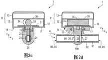
FIG. 2c is a transverse cross-sectional view of the flow meter subassembly inserted into the DN15 flow tube;
FIG. 2d is a longitudinal cross-sectional view of the flow meter subassembly inserted into the DN15 flow tube;
FIG. 3a is a schematic slight side view of a flow meter subassembly inserted into DN20 flow tube;
FIG. 3b is a schematic slight end view of the flow meter subassembly inserted into DN20 flow tube;
FIG. 3c is a transverse cross-sectional view of the flow meter subassembly inserted into the DN20 flow tube;
FIG. 3d is a longitudinal cross-sectional view of the flow meter subassembly inserted into the DN20 flow tube;
FIG. 4 is a side view of a flow measurement element including a printed circuit board, electrodes, a magnetic circuit, a sensing coil, and an auxiliary ground electrode;
FIG. 5 is a cross-sectional view of a flow measurement element inserted into the DN15 flow tube and showing magnetic field lines (lines of magnetic force) and induced electric fields generated by water flow through the flow tube;
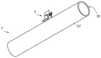
fig. 6a is a perspective view of a flow measuring element with a DN15 flow regulator;
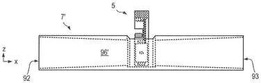
FIG. 6b is a side view of a flow measurement element having a DN15 flow regulator;
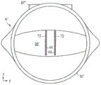
FIG. 7 is an end view of the flow measurement element in the DN20 flow tube;
fig. 8a is a perspective view of a flow measuring element with a DN20 flow regulator;
FIG. 8b is a side view of a flow measurement element having a DN20 flow regulator;
FIG. 9 is a side view of a flow measurement element and DN50 flow regulator;
FIG. 10 is an end view of the DN50 regulator tube showing the change in profile of the flow measurement element from a circular inlet and center position;
3 FIG. 3 11 3 is 3a 3 cross 3- 3 sectional 3 view 3 of 3 DN 3 50 3 flow 3 tube 3 taken 3 along 3 line 3A 3- 3A 3' 3 in 3 FIG. 3 9 3, 3 showing 3 the 3 installation 3 of 3a 3 flow 3 measurement 3 element 3 in 3 the 3 flow 3 tube 3; 3
FIG. 12 is an end view of an inserted flow measurement element in a flow tube having a printed circuit board electrode, a magnetic circuit, a sensing coil and an auxiliary ground electrode and showing magnetic field lines and induced electric fields caused by water flow through the flow tube;
FIG. 13 is a side view of an inserted flow element in a flow tube;
FIG. 14 is an exploded perspective view of another flow meter assembly including a flow meter subassembly having an insert that houses a flow measurement element that can be removably inserted into a flow tube and that can fit a range of different flow tube diameters;
FIG. 15a is a perspective view of the insert shown in FIG. 14;
FIG. 15b is an exploded perspective view of the insert shown in FIG. 14;
fig. 15c is a top plan view of the insert shown in fig. 14.
FIG. 15d is a side view of the insert shown in FIG. 14;
FIG. 15e is a cross-sectional view of the insert shown in FIG. 15d, taken along line C-C';
FIG. 15f is a front view of the insert shown in FIG. 14;
FIG. 15g is a cross-sectional view of the insert shown in FIG. 15f taken along line D-D'; and
fig. 16 shows a magnetic field generated by a magnetic circuit in the flow rate measurement element shown in fig. 14 and an electric field generated when water flows through the flow rate measurement element.
Detailed Description
Referring to fig. 1 and 2a to 2d, a first flow meter assembly 1 (referred to herein simply as a "flow meter") according to the present invention is shown.
The flow meter 1 can be used for water metering using battery powered electromagnetic induction for residential commercial and industrial use. In particular, the flow meter 1 may be used as a battery-powered fiscal water meter (meter) that meets recognized international standards for water metering accuracy.
The first flow meter assembly 1 includes a flow meter subassembly 2 (also referred to herein as a "meter unit") including a register 3 having an integrated insert 4 (or "plug") that includes a flow measuring element 5 (also referred to herein as a "flow measuring element," "flow sensor," or simply "sensor") that provides an electromagnetic flow sensor that is removably insertable into a generally tubular fluid housing 6 having an internal regulator tube 7. The fluid may be water or other form of electrically conductive fluid.
The water housing 6 may have a nominal diameter of 20mm, i.e. it is a DN20 fitting (or equivalent or corresponding NPS or us standard size). However, as will be described in more detail below, the plug 4 can be inserted into tubular water housings 6 of different sizes (e.g., DN15, DN50, etc.) to provide different sized flow meters (in other words, to provide water meters that can be used with different sized pipes).
Recorder 3-
Still referring to fig. 1 and 2 a-2 d, flowmeter subassembly 2 includes a housing 11 for a register 3 that includes a shallow plastic or metallic cylindrical can 12 and a shallow transparent cover 13 (referred to herein as a "window"). The housing 11 has a diameter d of about 75 mm.
The recorder tank 12 has a bottom edge 14 and a top edge 15 (also referred to herein as a "top edge"), a side wall 16 extending between the bottom edge 14 and the top edge 15, and a bottom end wall 17 having a central aperture 18. A collar 19 coaxial with the bore 18 depends from the bottom end wall 17 and has inwardly projecting pins 20 to provide the male part of a bayonet connector 21. Depending from the bottom end wall 17 is a depending "U" shaped plug 22 (or "insert") also aligned with the bore 18. The plug 22 includes first and second parallel plates 23, 24 (or "sidewalls") connected by a bottom cross-member 25, thereby defining first and second open faces 26, 27 and a passageway 28 between the faces 26, 27.
Still referring to fig. 1 and 2 a-2 d, the flow meter subassembly 2 includes a drive electronics module 29 (also referred to herein simply as "electronics") and a display 30 located in the recorder tank 12 below the window 13. The drive electronics module 29 includes a register Printed Circuit Board (PCB)31 that supports drive electronics (not shown) and an AA battery 33 held in place by a spring clip 34. The recorder canister 12 is filled with potting compound (not shown). The measuring element 5 is insertably connected to a connector 36 on the underside of the recorder PCB 31 and is encapsulated, for example with an encapsulating compound.
The electronic module 29 is maintained in a dry environment using standard methods (e.g., potting with glass metal structures, low water permeability plastics, desiccants, etc.).
A measuring element 5
With reference to fig. 1 and 2a to 2d, and also to fig. 4 and 5, the measuring element 5 takes the form of an interposed electromagnetic flow sensor.
The measuring element 5 comprises a first flat rectangular plate-like member 42 and a second flat rectangular plate-like member 43 facing each other in a symmetrical arrangement (i.e. symmetrical about the central plane P). Each component 42, 43 includes a PCB 44 having a first face 46 ("inward face") and a second face 48 ("outward face") extending between a first end 50 and a second end 51 ("lower end and upper end"), and between a first edge 54 and a second edge 55 ("front edge and rear edge"). Approximately two thirds of the way between the lower end 50 and the upper end 51, each PCB 44 has a slot 58 that extends from the front edge 54 toward the rear edge 55 but does not reach the rear edge 55.
Each PCB 44 supports a first rectangular electrode 60, a second rectangular electrode 61 and a third rectangular electrode 62 on a lower portion of its inward facing surface 46. Electrodes 60, 61, 62 are spaced between lower end 50 and slot 58. The second electrode 61 is interposed between the first electrode 60 and the third electrode 62 and provides a ground electrode.
The electrodes 60, 61, 62 are preferably anodized silver/silver chloride (Ag/AgCl) half cell electrodes formed on the inward facing surface 46 of the circuit board 44 using standard plating and etching processes. The electrodes 60, 61, 62 may be protected by an ion permeable coating (e.g., Nafion, perfluorosulfonic acid) or other porous material, which may be conductive (such as graphite) or insulating (such as ceramic or porous plastic). They may also be formed of an electrically conductive inert material, including graphite, conductive plastics, or inert metals.
For example, to improve flow measurement performance, multiple electrodes may be used as reference or bias electrodes and/or to detect when the sensor is full of water. In the embodiment shown, a single ground electrode 61 is used which can be used to bias the electronics for electrode input so that they are within an acceptable common mode input range.
Each PCB 44 also supports on a lower portion of its inward facing face 46 a sensing coil 66 for measuring the magnetic field B. Sensing coil 66 may include one or more loops connected to a set of connectors 68 at upper end 51 of sensor PCB 44 via conductive tracks 70.
Each PCB 44 supports a respective electrically insulating pole piece 72 on a lower portion of its outward facing face 48. The pole pieces 72 are insulated by, for example, brushing, coating or encapsulating the pole pieces 72 with an insulating material (not shown), or by placing the pole pieces 72 such that the surrounding plastic parts separate the pole pieces 72 or keep the pole pieces sufficiently far from the water flow that the pole pieces 72 do not short circuit the induced electromotive force. In use, the electrically insulated pole piece 72 is wetted. Each pole piece 72 is a thin sheet (e.g., strip) or piece (e.g., block or rod) of soft magnetic material, such as high permeability electrical stainless steel (e.g., 430FR), that extends from the lower end 50 toward the upper end 51 of the PCB 44. When the pole piece 72 reaches the slot 58, it is bent outwardly to form a narrow wing 74 (or "shelf).
An upper surface 76 of wing portion 74 supports one or more sheets (e.g., strips) or pieces 78 of residual magnetic material. The remanent magnetic material is a semi-hard magnetic material such as Vacuumschmelze SENSORVAC (RTM), Hitachi ZMG423 or MagneDur 20-4. The one or more residual magnetic components 78 pass through the drive coil 79 and bridge the two PCB 44 pole pieces 72.
The pole piece 72 is preferably made of permeable stainless steel, but other suitable soft magnetic materials may be used. This arrangement can eliminate the need to pass magnetic flux through the pressure resistant flow tube wall. This can help to increase the efficiency of field generation across the water (at a given magnetic drive power). This enables lower power consumption at a given flow sensitivity. This may also allow a greater variety of materials to be used to construct the flow tube wall.
It is preferred that the magnetic field be generated using a residual magnetic element 78 operating at a low frequency (such as 1Hz) to help reduce or minimize power consumption, thereby enabling the sensor to be powered using the battery 33.
The pole piece 72 may be mounted on a measuring insert or insert-molded (insert-molded) into the flow tube 6.
A tubular water housing 6-
Still referring to fig. 1 and 2a to 2d, the tubular water housing 6 comprises a tube wall 82 extending between a first open end 83 and a second open end 84 and providing a tubular space 85. The housing 6 further comprises an opening 86 provided midway between the first and second ends 83, 84, which opening is provided with a short annular collar 87 upstanding from the tube wall 82 and has a pair of "L" -shaped slots 88 recessed into the outer wall of the collar 87 on opposite sides of the collar 87, providing the female part of the bayonet connector 21.
The flowmeter subassembly 2 and the tubular water housing 6 are connected by a bayonet connector 21. A seal 89, such as an "O" ring, is located on an annular shelf 90 within the collar 87 and helps provide a watertight seal to help prevent or inhibit water from escaping from the housing 6.
The tubular housing 6 can be made of a number of different materials including metal and plastic. The metal may be a non-ferrous metal (such as bronze or brass) or a magnetic material (such as ductile iron) and may be coated with a suitable water resistant coating (such as epoxy or powder paint) to prevent corrosion. The tubular housing 6 may be disposed within a tubular magnetic shield (not shown). The shroud (not shown) may be formed of mild steel or other suitable material. The shield (not shown) may have a plastic coating (not shown) for purposes such as aesthetics and/or electrical insulation.
A regulating tube 7
Still referring to fig. 1 and 2 a-2 d and to fig. 6a and 6b, the adjustment tube 7 comprises a tube wall 91 extending between a first open end 92 and a second open end 93 and having an inner wall surface 94 and an outer wall surface 95. The inner wall surface 94 provides a flow passage 96. The profile of the passageway 96 generally narrows from the first end 92 of the tube 7 towards the intermediate portion 97 to accelerate the water velocity through the sensor (typically by a factor of 2 to 3) and thus increase the signal generation between the electrodes (at a given volumetric flow rate). The transverse cross-sectional profile of the passageway 96 may also be varied from circular or oval to rectangular to match the size of the flow measuring element.
At the middle portion 97 of the tube 7, the tube wall 91 includes a longitudinally oriented slot 98. The slot 98 is contoured and dimensioned to receive the plug 22 and thereby insert the flow measurement element 5 into the flow passage 96. Tube wall 91 may include another slot 99 on the opposite side of tube 7 to allow the distal end of plug 22 to pass through and out of the tube.
Different gauge sizes
A single insert element 4 can be used for a range of flow tube sizes, i.e. a range of water housing sizes.
With particular reference to fig. 2a to 2d and 5, for the smallest dimension of the housing 6 (DN 15 in this case), the sensor element 4 is slightly oversized for the size of the flow tube. This is mediated by a protrusion 100 (best shown in fig. 2 d) in the outer housing 6 so that the sensors 4 are symmetrically positioned.
Still referring to fig. 6a and 6b, the only path of water through the meter is through the sensor element 4, and the flow regulating plastic inserts 7 are used to accelerate and decelerate the flow upstream and downstream in order to minimize unrecoverable head losses.
With particular reference to fig. 3a to 3d and fig. 7, the DN20 meter follows a similar (configuration) pattern, but in this case the sensing element 4 fits exactly to the bottom of the flow tube. In this case, the housing 6' is sized to be connected to a DN20 fitting.
With reference to fig. 8a and 8b, the flow regulating plastic part 7' controls the transition from circular to accelerated rectangular area and back again to circular (profile).
In the DN15 and DN20 meters, the rectangular section modulating tubes 7, 7 ″ can provide sensitivity almost completely independent of flow profile, effective generation of magnetic field, large signal generation due to aspect ratio, and large signal generation due to two to three times acceleration of flow velocity relative to a circular path.
Larger size meters require the use of a different approach because it is not possible to pass the full flow of, for example, a DN50 meter through a small hole inserted into the flow sensor.
Referring to fig. 9, 10 and 11, there is shown an arrangement which can achieve this. The flow regulating element is arranged so that the orifice of the insert element 4 is kept in the centre of the reduced orifice flow area so that the influence of the flow profile, such as elbows and valves, is minimal to disturb the accuracy. The flow regulating member 7 "is configured to maintain a good immunity (immunity) to the flow profile at these larger dimensions. If the flow regulating element is arranged to provide the same acceleration in velocity as in the smaller size, while the power requirement for generating the magnetic field is the same as in the smaller diameter meter, the signal-to-noise ratio of the larger diameter meter should match that of the smaller size.
Second flow measurement component 104
Referring to fig. 12 and 13, a second measurement element 104 is shown. The second flow measurement component 104 is similar to the first measurement component 5 (fig. 1) described above and can be used as the measurement component in the flow meter assembly 1 (fig. 1) described above.
The second flow measurement component 104 differs in that the first and second printed circuit boards 144 sandwich a central component 172 (e.g., in the form of a strip) of soft magnetic material having opposing first and second sides 174, 175.
Each circuit board 144 has at least two electrodes 160, 161, 162 to measure the differential signal caused when water flows through the sensor. In the most common configuration, the electrodes 160, 161, 162 are connected in an anti-parallel configuration, since the flow direction of the electric field E induced by the flow is opposite on both sides of the sensor 104. This results in a balanced system with respect to a uniform external field.
The magnetic circuit is formed by an electrically insulated, generally rectangular outer part 173 of soft magnetic material and a central planar pole piece 172 sandwiched between two circuit boards 144. These components are preferably permeable stainless steel coated with an insulating material (e.g., PTFE, powder coating, epoxy, paint, varnish, or polymer).
The field generating element 178 is located between the outer box 173 and the central element 172. One or more residual magnetic elements 178 (which may take the form of bands, rods, or other components having suitable geometries) pass through the coil 179.
The flow conditioning element should be insulating and closely fit to the external magnetic circuit part 173 to avoid shorting of the electrode signal through water or through another path where a conductive flow tube (e.g., a conductive water housing) is used. The flow conditioning element requires an additional plane of insulation aligned with the central magnetic element 172 to avoid signal shorting near the sides of the circuit board 144.
A plurality of measuring electrodes 160, 161, 162 are provided on the insertion element. The electrodes 160, 161, 162 on the two PCBs 144 can either be connected anti-parallel (in series if the axial length of the insulator and tuning element is long enough) depending on the geometry, or they can simply be connected to other differential electrode inputs in the electronics. The latter configuration provides one such method: the flow profile impact free sensor is synthesized by allowing any combination of signals from the multi-component power distribution poles to be combined together in software, thereby managing severe flow profile (flow distribution) non-uniformities.
The precise location of the electrodes 160, 161, 162 on the circuit board 144 may be varied to tune the design to the response of laminar flow to turbulent flow to minimize any change in sensitivity to flow rate.
The second measurement element 104 may provide improved immunity to external magnetic fields. If regulations (e.g., eu metrology instrument directives), regulatory agencies, manufacturers, utilities, or other interested parties require protection from external electric fields, an additional external magnetic shield (not shown) may be omitted. This is because the outer box 173 may act as a magnetic shield.
Referring to FIG. 14, a second flow meter assembly 201 (referred to herein simply as a "flow meter") according to the present invention is shown.
The second flow meter assembly 201 includes a flow meter subassembly 202, the flow meter subassembly 202 including a register 203 having an integrated insert 204 (or "plug") that includes a flow measuring element 205 (also referred to herein as a "flow measuring element," "flow sensor," or simply "sensor") that provides an electromagnetic flow sensor that is removably inserted into a generally tubular water housing 206 having an internal regulator tube (not shown).
The second flow meter assembly 201 is similar to the first flow meter assembly 1 (fig. 1). The second flow meter assembly 201 differs primarily in the construction of the flow measurement element 205.
Recorder 203-
Still referring to fig. 14, recorder 203 is similar to recorder 3 (fig. 1) described above. The recorder 203 comprises a housing comprising a metallic cylindrical can 212 and a flat transparent window 213 provided with a peripheral window seal 208. The housing 211 has a diameter d of about 75 mm.
The housing 211 contains drive electronics 229 and a display 230 that are substantially the same as or similar to those previously described and therefore will not be described in detail herein.
As previously described, the second flow meter assembly 201 differs from the first flow meter assembly 1 (fig. 1) primarily in the construction of the flow measuring element 205.
In the first flow meter assembly 1 (fig. 1), the first flow measuring element 5 (fig. 1) includes flat, rectangular plate-like sensor portions 42, 43 (fig. 1), with a channel (fig. 1) defined between the sensor portions 42, 43 that presents a vertically oriented rectangular profile with respect to water flow.
The second flow measuring element 5 (fig. 12) comprises two channels, each of which has a rectangular profile oriented vertically with respect to the water flow. Thus, each half may be considered a separate rectangular unit. The electronics can process each half independently or connect the electrodes together in series.
In the second flow meter assembly 201, the third flow measurement element 205 defines a channel that is "U" shaped in profile with respect to water flow, as will be described in greater detail herein.
Still referring to fig. 15 a-15 g, insert 204 includes a body 241 that is generally cylindrical and symmetrical about a central vertical plane (not shown). The insert body 241 has a first end 242 and a second end 243 (referred to herein as the "bottom" and "top" of the body, respectively) and an outer wall 244 extending between the bottom 242 and top 243 of the insert.
The insert body 204 includes a lower portion 245 and an upper portion 246 separated by an interior bottom panel 247.
The lower body portion 245 of the insert body 204 includes a generally "U" shaped wall 248 that includes first and second flat sidewall portions 249, 250 and a curved bottom wall portion 251. The wall 248 extends between a first end 253 and a second end 254 (referred to herein as "front" and "rear," respectively). The wall 248 defines a cavity 252 (also referred to herein as a "flow passage" or simply a "passage"). The lower body portion 245 includes a front curtain wall 255 that extends approximately halfway between the bottom panel 247 and the bottom 244.
The "U" shaped wall 248 and the curtain wall 255 define a first aperture 256 and a second aperture 257 having an inverted arch window profile. The height of the first aperture 256 is less than the height of the second aperture 257 due to the presence of the curtain wall 255.
An oval cookie cutter-shaped frame 258 (also referred to herein as a "shaper") having generally flat sides protrudes from an inner surface 259 of curtain wall 255 through cavity 252. At the top 260 of the frame 258, the frame 258 extends (lowers) two sets of vertical walls 261, 262 downward, forming a wider upper channel 263 with a shelf 264 and a narrower lower channel 265 with a bottom 266, forming a "U" shaped lower channel portion 267 and two generally triangular shaped upper channel portions 268. The lowered portions of the frame 258 (i.e., the walls 261, 262, the shelf 264, and the bottom 266) form a central protrusion that provides an insulating barrier. The bottom of the frame 258 drops below the lower edge of the wall 255 proximate the bottom 269 of the cavity 252.
A generally annular space 270 is defined between the interior side of body wall 248 and the exterior side of frame 258.
The upper body portion 246 of the insert body 204 includes an annular wall 271 that is divided into a lower annular wall portion 272 and an upper annular wall portion 273. The lower wall portion 272 has a smaller inner and outer diameter than the upper wall portion 273, defining an inner step 274 and an outer step 275 in the wall 271. The lower wall portion 272 includes a radially outwardly projecting annular rib 276 that extends around the outside of the lower wall portion 262 along the bottom edge thereof. The outer step 275 and the rib 276 define an annular groove 277 that can receive an O-ring 278. The upper annular wall portion 273 is provided with a radially outwardly projecting lip 279 having an inclined upper edge 280 and a flat lower edge 281, thereby defining a barb profile.
Still referring to fig. 14 and 15a to 15g, the measuring element 205 is assembled within the body 241 of the insert 204, in particular the surrounding frame 258.
The insert 204 includes a magnetic circuit 291 comprising: a central element 292 of soft magnetic material (e.g., a sheet, rod, or other component having a suitable geometry); first and second elements 293 (e.g., sheets, rods, or other components having suitable geometries) of residual magnetic material passing through electromagnetic coil 294; and a two-piece magnetic material ring 295 (or "yoke") that includes a generally "U" shaped portion 296 and a cover portion 297. Pole piece 292 comprises a soft magnetic material. The central element 292 provides a central pole.
The pole piece 292 may be sandwiched between two PCBs 244, which electrically insulates the pole piece 292.
The insert 204 further comprises an electric field measuring device comprising first and second electrodes 298 and first and second electrode connecting rods 299. The connecting rod 299 and the coil connecting wire 300 are connected to the flexible connector 301. The electrode 298 and the electrode connecting rod preferably comprise graphite.
The electrodes 298 are generally triangular prism-shaped and are disposed in the respective triangular channel portions 268. The electrodes 298 may take other shapes, such as bands, rods, strips, and the like. The connecting rods 299 pass through corresponding through holes (not shown) in the divider plate 247 and mate with corresponding blind holes (not shown) in the electrodes 298.
The pole piece 292 is disposed in the lower inner frame channel 265 and the coil 294 is disposed in the upper inner frame channel 263. A two-piece ring of magnetic material 295 is located in the outer frame space 270. Insert 204 may be filled with potting material 302.
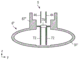
Referring to fig. 16, in this configuration, the magnetic field B passes laterally and radially downward from the pole piece 292 toward the ring of magnetic material 295. The flow of water through the space filled with the magnetic field causes an electric field to be generated, which is sensed by the electrodes 298.
Modifications of the type
It will be understood that various modifications may be made to the embodiments described hereinbefore. Such modifications may involve equivalent and other features which are already known in the design, manufacture and use of electromagnetic flow meters and component parts thereof and which may be used instead of or in addition to features already described herein. Features from one embodiment may be substituted for or supplemented by features from another embodiment.
Mounting of
The flow meter subassembly does not have to be removably mounted to the housing using a bayonet connector. Other forms of detachable connectors may be used, for example a connector similar to that used for detachable hose connections may be used. Moreover, the flow meter subassembly can be permanently installed.
Flow regulation
The flow regulating element may have different geometries, especially for larger sizes. The typical lay length of a larger meter provides enough space to manage the flow profile so that the insert element itself passes the same flow regardless of upstream or downstream conditions.
Electrode for electrochemical cell
Multiple measuring electrodes may be used on the insertion element. These electrodes may be connected in parallel, depending on the geometry, or may simply be connected to further electrode inputs in the electronic device. The latter configuration provides one such method: severe flow profile (flow distribution) non-uniformity is managed by allowing any combination of signals from multi-component power distribution poles to be combined together in software to synthesize a sensor that is immune to flow profile effects. Other commonly used electrode materials may be used regardless of the features of the present invention.
Magnetic device
The magnetic field may be generated using a residual magnetic element, a conventional solenoid, or other bi-stable or rotating magnetic component. The mode of operation (field versus time) of the meter may vary, regardless of the core features of the invention.
Material
Soft magnetic components (e.g., pole pieces) can be made from electrical steel, soft ferrites, magnetic stainless steels (such as 9CR (available from Vacuumschmelze GmbH & co, KG, germany), Chrome Core 12FM), and the like. Soft magnetic components may be made of non-stainless steel or other corrodible materials (e.g., CoFe) as long as they have a protective coating or are otherwise protected from rust or other corrosion.
Semi-hard (magnetic) component materials (i.e., remanent magnetic elements) may include SENSORVAC (RTM) (available from Vacuumschmelze GmbH & Co., KG, Germany), and the like.
The electrodes may be made of graphite, platinum, gold, silver/silver chloride, conductive plastic, stainless steel, and the like.
The insulation may be formed of plastic (such as PPS, ABS) or acrylic, glass, epoxy, paint, varnish, oxide or powder coating (e.g. polyester).
The components of the sensor may be made of (non-magnetic) brass or 316L stainless steel, powder coated cast or ductile iron, and/or (magnetic) magnetic stainless steel, such as 12FM (available from Ugitech). Any water compatible polymer (including PPS, polyamide, polypropylene) may be used for the wetted electrically and magnetically inert components.
Magnetic stainless steel can serve as both a water ground (water ground) and a magnetic shield, as well as an outer pole piece for the inner/outer pole geometry. The ground may have an electrically safe ground continuity across the meter (flow meter) and/or may be an electrical reference point (electrical reference point) connected to the electronics to provide immunity to common mode electrical interference.
The meter (flow meter) described above can be used to measure the flow of other forms of conductive liquids, such as ionic liquids.
Although claims have been formulated in this application to particular combinations of features, it should be understood that the scope of the disclosure of the present invention also includes any novel feature or any novel combination of features disclosed herein either explicitly or implicitly or any generalisation thereof, whether or not it relates to the same invention as presently claimed in any claim and whether or not it mitigates any or all of the same technical problems as does the present invention. The applicants hereby give notice that new claims may be formulated to such features and/or combinations of such features during the prosecution of the present application or of any further application derived therefrom.
Claims (14)
1. An electromagnetic flow sensor for an electromagnetic flow meter (201), the sensor comprising:
a body (204) or frame;
a passageway (252) through the body or frame;
a component (248, 295) of a magnetic circuit supported by the body or frame for directing a magnetic field through the passage; and
at least first and second electrodes (298) supported by the body or frame, the at least first and second electrodes being arranged to sense a voltage in response to a conductive fluid flowing through the passageway;
wherein the components of the magnetic circuit comprise:
a central pole piece (172, 292); and
an outer pole piece (173, 295) extending around the central pole piece and the passage to act as a magnetic screen shielding an external magnetic field,
wherein the passageway has a central protrusion (261, 262, 264, 266) extending into and along the passageway such that the passageway has a profile relative to the flow of the conductive fluid that enables the conductive fluid to self-retrace, wherein the central protrusion is electrically insulating and contains the central pole piece.
2. The sensor of claim 1, wherein the components of the magnetic circuit are electrically insulated from the conductive fluid.
3. The sensor of claim 1, wherein at least a portion of the body or frame supporting components of the magnetic circuit and at least the first and second electrodes is configured to be insertable into a flow tube through a single aperture in the flow tube.
4. The sensor of any preceding claim, wherein the magnetic screen comprises a magnetic material of sufficient thickness to avoid magnetic saturation when a magnet having a strength dictated by meter instructions is affixed to the flow meter.
5. A sensor according to any one of claims 1 to 3, wherein, in use, the body or frame is in direct contact with the electrically conductive fluid and the electrically conductive parts other than the at least first and second electrodes are each electrically insulated from the electrically conductive fluid.
6. A subassembly, comprising:
an electromagnetic flow sensor as claimed in any preceding claim; and
a meter register;
wherein the electromagnetic flow sensor and the flow sensor form a single unit.
7. A sub-assembly according to claim 6, wherein the components of the magnetic circuit and the electrode are integrally formed in the meter register.
8. An electromagnetic flow meter comprising:
the sensor of any one of claims 1 to 5.
9. An electromagnetic flow meter comprising:
a tubular fluid housing having a fluid housing wall and a fluid housing bore in the fluid housing wall;
an optional conditioning tube disposed within the fluid housing and having a fluid conditioning tube wall and a conditioning tube aperture in the conditioning tube wall; and
the sensor of any one of claims 1 to 5 or the sub-assembly comprising a sensor according to claim 6 or 7 inserted into the tubular fluid housing so as to pass partially through the fluid housing aperture and at least partially through the regulator tube aperture.
10. The flow meter of claim 9, wherein the sensor is removably inserted into the tubular housing.
11. The flowmeter of claim 9, wherein the tubular housing is a tee pipe.
12. A flow meter according to any of claims 9 to 11, which is a full flow meter.
13. The flowmeter of any of claims 9 to 11, wherein the flowmeter body is configured to provide electrically safe ground continuity across the entire flowmeter.
14. The flow meter according to any of claims 9 to 11, wherein the flow meter body is configured to provide an electrical reference point for the electronics module.
Applications Claiming Priority (5)
| Application Number | Priority Date | Filing Date | Title |
|---|---|---|---|
| GBGB1513271.5A GB201513271D0 (en) | 2015-07-28 | 2015-07-28 | Modular flow meter |
| GB1513271.5 | 2015-07-28 | ||
| GBGB1515159.0A GB201515159D0 (en) | 2015-08-26 | 2015-08-26 | Improved modular flow meter |
| GB1515159.0 | 2015-08-26 | ||
| PCT/GB2016/052323 WO2017017463A1 (en) | 2015-07-28 | 2016-07-28 | Electromagnetic flow sensor |
Publications (2)
| Publication Number | Publication Date |
|---|---|
| CN107923776A CN107923776A (en) | 2018-04-17 |
| CN107923776B true CN107923776B (en) | 2020-05-19 |
Family
ID=56567632
Family Applications (1)
| Application Number | Title | Priority Date | Filing Date |
|---|---|---|---|
| CN201680044465.4A Active CN107923776B (en) | 2015-07-28 | 2016-07-28 | Electromagnetic flow sensor |
Country Status (16)
| Country | Link |
|---|---|
| US (1) | US11054291B2 (en) |
| EP (2) | EP3329220A1 (en) |
| JP (1) | JP2018525626A (en) |
| KR (1) | KR20180044301A (en) |
| CN (1) | CN107923776B (en) |
| AU (1) | AU2016299404B2 (en) |
| BR (1) | BR112018001384A2 (en) |
| CA (1) | CA2992919A1 (en) |
| CL (1) | CL2018000239A1 (en) |
| CO (1) | CO2018000981A2 (en) |
| ES (1) | ES2796124T3 (en) |
| MX (1) | MX2018001099A (en) |
| RU (1) | RU2018106882A (en) |
| SA (1) | SA518390810B1 (en) |
| WO (1) | WO2017017463A1 (en) |
| ZA (1) | ZA201800603B (en) |
Families Citing this family (25)
| Publication number | Priority date | Publication date | Assignee | Title |
|---|---|---|---|---|
| DE102016123123A1 (en) * | 2016-11-30 | 2018-05-30 | Endress+Hauser Flowtec Ag | Magnetic-inductive flowmeter |
| DE102017112950A1 (en) * | 2017-06-13 | 2018-12-13 | Krohne Messtechnik Gmbh | Magnetic-inductive flowmeter and method for operating a magnetic-inductive flowmeter |
| IT201700112704A1 (en) * | 2017-10-06 | 2019-04-06 | Eltek Spa | HYDRAULIC CONTROL DEVICE FOR LIQUID DUCTED APPLIANCES OR SYSTEMS |
| IT201700112681A1 (en) * | 2017-10-06 | 2019-04-06 | Eltek Spa | HYDRAULIC CONTROL DEVICE FOR LIQUID CONDUCTOR EQUIPMENT AND SYSTEMS |
| IT201700112670A1 (en) * | 2017-10-06 | 2019-04-06 | Eltek Spa | SAFETY DEVICE AGAINST LIQUID LEAKS FOR LIQUID DUCTED HOUSEHOLD APPLIANCES |
| IT201800002751A1 (en) * | 2018-02-16 | 2019-08-16 | Eltek Spa | DETECTION AND / OR CONTROL DEVICE FOR LIQUID-CONDUCTED EQUIPMENT OR SYSTEMS |
| USD867913S1 (en) * | 2018-03-16 | 2019-11-26 | General Electric Company | Flow sensor |
| GB201814762D0 (en) * | 2018-09-11 | 2018-10-24 | Sentec Ltd | Insert electromagnetic flow sensor for centrifugal pump |
| US11029180B2 (en) * | 2018-10-16 | 2021-06-08 | Corey CRAIG | Fluid metering component and spraying apparatuses thereof |
| US11925949B1 (en) | 2018-10-16 | 2024-03-12 | Optix Technologies, LLC | Fluid metering component and spraying apparatus thereof |
| DE102018125865B4 (en) * | 2018-10-18 | 2022-12-22 | Krohne Ag | Electromagnetic flowmeters, magnetic circuit devices and method of manufacturing a magnetic circuit device |
| DE102018132600B4 (en) * | 2018-12-18 | 2024-02-22 | Endress+Hauser Flowtec Ag | Magnetic-inductive flow measuring probe and measuring point for determining a flow and/or an installation angle |
| US10718644B1 (en) * | 2019-01-03 | 2020-07-21 | Dwyer Instruments, Inc. | Sensor head for insertion electromagnetic flow meter |
| US11378429B2 (en) * | 2019-02-22 | 2022-07-05 | Onicon Incorporated | Insertion magnetic meters and methods |
| CN110231063A (en) * | 2019-05-30 | 2019-09-13 | 江阴市富仁高科股份有限公司 | A kind of gas flowmeter detecting oil gas |
| GB201910986D0 (en) * | 2019-08-01 | 2019-09-18 | Sentec Ltd | Insert electromagnetic flow sensor for centrifugal pump |
| GB201911971D0 (en) * | 2019-08-21 | 2019-10-02 | Sentec Ltd | Improved electrode |
| US11175169B2 (en) * | 2019-08-29 | 2021-11-16 | Sensus Spectrum, Llc | Systems for connecting a central module to a network and related connectors |
| CN110905483B (en) * | 2019-11-07 | 2023-03-21 | 西安康际石油科技有限公司 | Integrated flowmeter for microwave water content and flow of oil field |
| NL2024318B1 (en) * | 2019-11-27 | 2021-08-30 | Fnv Ip Bv | Electric field gradient sensor |
| CN112179430A (en) * | 2020-09-30 | 2021-01-05 | 湖南常德牌水表制造有限公司 | Ultrasonic water meter anti-interference protection device |
| EP3982090A1 (en) * | 2020-10-09 | 2022-04-13 | Husqvarna Ab | Metering console |
| KR20220060148A (en) | 2020-11-04 | 2022-05-11 | ㈜위드유 | Water cut meter using microwave resonance |
| EP4278156A1 (en) * | 2021-01-12 | 2023-11-22 | Micro Motion, Inc. | Interface with improved accessibility |
| KR20230112213A (en) | 2022-01-20 | 2023-07-27 | ㈜위드유 | System for verifying the accuracy of water cut meters |
Citations (5)
| Publication number | Priority date | Publication date | Assignee | Title |
|---|---|---|---|---|
| CN2115521U (en) * | 1992-01-24 | 1992-09-09 | 天津市自动化仪表三厂 | Insert type electromagnetic flow sensor |
| US5325728A (en) * | 1993-06-22 | 1994-07-05 | Medtronic, Inc. | Electromagnetic flow meter |
| CN2449199Y (en) * | 2000-11-21 | 2001-09-19 | 陈宝荣 | Intelligent electromagnetic flow meter |
| CN102840356A (en) * | 2012-08-23 | 2012-12-26 | 杭州云谷科技有限公司 | Electromagnetic flow measurement and control integrated device |
| CN103140742A (en) * | 2010-08-03 | 2013-06-05 | 李·古文斯 | Electromagnetic flow meter |
Family Cites Families (13)
| Publication number | Priority date | Publication date | Assignee | Title |
|---|---|---|---|---|
| DE3236909A1 (en) * | 1982-10-06 | 1984-04-12 | Turbo-Werk Messtechnik GmbH, 5000 Köln | MEASURING DEVICE FOR INDUCTIVE MEASUREMENT OF THE FLOW SPEED OF LIQUID MEDIA |
| DE3501768A1 (en) | 1985-01-21 | 1986-07-24 | Danfoss A/S, Nordborg | ELECTROMAGNETIC FLOW METER |
| JPH01140021A (en) * | 1987-11-26 | 1989-06-01 | Yamatake Honeywell Co Ltd | Electromagnetic flowmeter |
| CN1067738C (en) * | 1996-12-19 | 2001-06-27 | 中国工程物理研究院应用电子学研究所 | Underground electromagnetic flowmeter |
| JP2969514B2 (en) * | 1997-08-27 | 1999-11-02 | 日本ピラー工業株式会社 | Mounting structure of sensor for fluid measurement |
| EP1125098B1 (en) * | 1998-09-29 | 2016-07-27 | Scientific Generics Limited | Magnetic flow meter |
| CN1299099C (en) * | 2001-02-06 | 2007-02-07 | 埃尔斯特计量有限公司 | Flowmeter |
| US6983661B2 (en) * | 2003-05-15 | 2006-01-10 | Endress + Hauser Flowtec Ag | Electromagnetic flow sensor |
| CN1712907A (en) * | 2005-07-13 | 2005-12-28 | 吉林大学 | Turbine electromagnetic flowmeter with low starting output volume |
| US7437945B1 (en) * | 2008-02-14 | 2008-10-21 | Murray F Feller | Magnetic flow probe |
| US20090205400A1 (en) * | 2008-02-16 | 2009-08-20 | Luther Donald Mcpeak | System and method for measuring fluid flow |
| US7779702B2 (en) * | 2008-11-03 | 2010-08-24 | Rosemount Inc. | Flow disturbance compensation for magnetic flowmeter |
| JP2012008108A (en) * | 2010-06-28 | 2012-01-12 | Toshiba Corp | Electromagnetic flow meter |
-
2016
- 2016-07-28 JP JP2018504093A patent/JP2018525626A/en active Pending
- 2016-07-28 RU RU2018106882A patent/RU2018106882A/en not_active Application Discontinuation
- 2016-07-28 EP EP16747581.3A patent/EP3329220A1/en not_active Withdrawn
- 2016-07-28 WO PCT/GB2016/052323 patent/WO2017017463A1/en active Application Filing
- 2016-07-28 US US15/747,560 patent/US11054291B2/en active Active
- 2016-07-28 ES ES18194819T patent/ES2796124T3/en active Active
- 2016-07-28 KR KR1020187006043A patent/KR20180044301A/en unknown
- 2016-07-28 CN CN201680044465.4A patent/CN107923776B/en active Active
- 2016-07-28 EP EP18194819.1A patent/EP3435040B1/en active Active
- 2016-07-28 AU AU2016299404A patent/AU2016299404B2/en active Active
- 2016-07-28 CA CA2992919A patent/CA2992919A1/en not_active Abandoned
- 2016-07-28 MX MX2018001099A patent/MX2018001099A/en unknown
- 2016-07-28 BR BR112018001384A patent/BR112018001384A2/en not_active Application Discontinuation
-
2018
- 2018-01-25 SA SA518390810A patent/SA518390810B1/en unknown
- 2018-01-26 CL CL2018000239A patent/CL2018000239A1/en unknown
- 2018-01-29 ZA ZA2018/00603A patent/ZA201800603B/en unknown
- 2018-01-30 CO CONC2018/0000981A patent/CO2018000981A2/en unknown
Patent Citations (5)
| Publication number | Priority date | Publication date | Assignee | Title |
|---|---|---|---|---|
| CN2115521U (en) * | 1992-01-24 | 1992-09-09 | 天津市自动化仪表三厂 | Insert type electromagnetic flow sensor |
| US5325728A (en) * | 1993-06-22 | 1994-07-05 | Medtronic, Inc. | Electromagnetic flow meter |
| CN2449199Y (en) * | 2000-11-21 | 2001-09-19 | 陈宝荣 | Intelligent electromagnetic flow meter |
| CN103140742A (en) * | 2010-08-03 | 2013-06-05 | 李·古文斯 | Electromagnetic flow meter |
| CN102840356A (en) * | 2012-08-23 | 2012-12-26 | 杭州云谷科技有限公司 | Electromagnetic flow measurement and control integrated device |
Also Published As
| Publication number | Publication date |
|---|---|
| CL2018000239A1 (en) | 2018-07-13 |
| EP3435040B1 (en) | 2020-03-25 |
| KR20180044301A (en) | 2018-05-02 |
| CA2992919A1 (en) | 2017-02-02 |
| WO2017017463A1 (en) | 2017-02-02 |
| ZA201800603B (en) | 2019-07-31 |
| CO2018000981A2 (en) | 2018-06-12 |
| AU2016299404A1 (en) | 2018-02-15 |
| ES2796124T3 (en) | 2020-11-25 |
| US11054291B2 (en) | 2021-07-06 |
| JP2018525626A (en) | 2018-09-06 |
| EP3435040A1 (en) | 2019-01-30 |
| AU2016299404B2 (en) | 2021-02-04 |
| MX2018001099A (en) | 2018-07-06 |
| SA518390810B1 (en) | 2021-09-05 |
| BR112018001384A2 (en) | 2018-09-11 |
| CN107923776A (en) | 2018-04-17 |
| RU2018106882A (en) | 2019-08-28 |
| US20180216978A1 (en) | 2018-08-02 |
| EP3329220A1 (en) | 2018-06-06 |
Similar Documents
| Publication | Publication Date | Title |
|---|---|---|
| CN107923776B (en) | Electromagnetic flow sensor | |
| US8826743B2 (en) | Magnetic inductive flow meter having magnetic poles distributing uniform magnetic field lines over the entire pole surface | |
| JP5887683B2 (en) | Electromagnetic flow meter | |
| CN109891200B (en) | Electromagnetic flowmeter | |
| KR20070100417A (en) | Magnetic flow meter with unibody construction and conductive polymer electrodes | |
| AU2016309618B2 (en) | Inductive flow meter including extended magnetic pole pieces | |
| US9709426B2 (en) | Magnetic-inductive flowmeter | |
| CN219084148U (en) | Electromagnetic water meter | |
| CN104019860A (en) | Flowmeter integrating electromagnetism and ultrasonic and use method of flowmeter | |
| RU2398190C2 (en) | Flow sensor and connection element | |
| CN211824561U (en) | Low-power consumption and wide-range electromagnetic water meter sensor | |
| CN116734934B (en) | Compact electromagnetic flowmeter, installation method and flow measuring method | |
| EP4007893B1 (en) | Insert-type electromagnetic flow meter | |
| CN203657868U (en) | Electromagnetic and ultrasonic integrated-design flow meter | |
| CN211978009U (en) | Electromagnetic flowmeter assembly | |
| CN114705259A (en) | Excitation device of miniaturized electromagnetic flow sensor | |
| CN114674383A (en) | Electrode and extraction device of miniaturized electromagnetic flow sensor |
Legal Events
| Date | Code | Title | Description |
|---|---|---|---|
| PB01 | Publication | ||
| PB01 | Publication | ||
| SE01 | Entry into force of request for substantive examination | ||
| GR01 | Patent grant | ||
| GR01 | Patent grant |