EP3435040B1 - Electromagnetic flow sensor - Google Patents
Electromagnetic flow sensor Download PDFInfo
- Publication number
- EP3435040B1 EP3435040B1 EP18194819.1A EP18194819A EP3435040B1 EP 3435040 B1 EP3435040 B1 EP 3435040B1 EP 18194819 A EP18194819 A EP 18194819A EP 3435040 B1 EP3435040 B1 EP 3435040B1
- Authority
- EP
- European Patent Office
- Prior art keywords
- flow
- meter
- sensor
- electrodes
- magnetic
- Prior art date
- Legal status (The legal status is an assumption and is not a legal conclusion. Google has not performed a legal analysis and makes no representation as to the accuracy of the status listed.)
- Active
Links
- 230000005291 magnetic effect Effects 0.000 claims description 61
- 239000012530 fluid Substances 0.000 claims description 28
- 230000003750 conditioning effect Effects 0.000 claims description 23
- 239000000696 magnetic material Substances 0.000 claims description 16
- 230000004044 response Effects 0.000 claims description 3
- XLYOFNOQVPJJNP-UHFFFAOYSA-N water Substances O XLYOFNOQVPJJNP-UHFFFAOYSA-N 0.000 description 38
- 238000005259 measurement Methods 0.000 description 22
- 239000004033 plastic Substances 0.000 description 12
- 229920003023 plastic Polymers 0.000 description 12
- 238000003780 insertion Methods 0.000 description 9
- 230000037431 insertion Effects 0.000 description 9
- 239000000463 material Substances 0.000 description 8
- ALDJIKXAHSDLLB-UHFFFAOYSA-N 1,2-dichloro-3-(2,5-dichlorophenyl)benzene Chemical compound ClC1=CC=C(Cl)C(C=2C(=C(Cl)C=CC=2)Cl)=C1 ALDJIKXAHSDLLB-UHFFFAOYSA-N 0.000 description 7
- 229910052751 metal Inorganic materials 0.000 description 7
- 239000002184 metal Substances 0.000 description 7
- 229910001220 stainless steel Inorganic materials 0.000 description 7
- 230000005684 electric field Effects 0.000 description 6
- 239000011248 coating agent Substances 0.000 description 5
- 238000000576 coating method Methods 0.000 description 5
- 238000004382 potting Methods 0.000 description 5
- 230000035945 sensitivity Effects 0.000 description 5
- 239000010935 stainless steel Substances 0.000 description 5
- OKTJSMMVPCPJKN-UHFFFAOYSA-N Carbon Chemical compound [C] OKTJSMMVPCPJKN-UHFFFAOYSA-N 0.000 description 4
- 230000008859 change Effects 0.000 description 4
- 230000000694 effects Effects 0.000 description 4
- 229910002804 graphite Inorganic materials 0.000 description 4
- 239000010439 graphite Substances 0.000 description 4
- 230000036039 immunity Effects 0.000 description 4
- 150000003071 polychlorinated biphenyls Chemical class 0.000 description 4
- 239000000523 sample Substances 0.000 description 4
- 239000004593 Epoxy Substances 0.000 description 3
- 229910021607 Silver chloride Inorganic materials 0.000 description 3
- -1 bronze or brass Chemical compound 0.000 description 3
- 150000001875 compounds Chemical class 0.000 description 3
- 230000004907 flux Effects 0.000 description 3
- 238000004519 manufacturing process Methods 0.000 description 3
- 150000002739 metals Chemical class 0.000 description 3
- 238000012986 modification Methods 0.000 description 3
- 230000004048 modification Effects 0.000 description 3
- 239000000843 powder Substances 0.000 description 3
- HKZLPVFGJNLROG-UHFFFAOYSA-M silver monochloride Chemical compound [Cl-].[Ag+] HKZLPVFGJNLROG-UHFFFAOYSA-M 0.000 description 3
- 229910001369 Brass Inorganic materials 0.000 description 2
- 229910001141 Ductile iron Inorganic materials 0.000 description 2
- 239000008280 blood Substances 0.000 description 2
- 210000004369 blood Anatomy 0.000 description 2
- 239000010951 brass Substances 0.000 description 2
- 230000007797 corrosion Effects 0.000 description 2
- 238000005260 corrosion Methods 0.000 description 2
- 238000013461 design Methods 0.000 description 2
- 230000009977 dual effect Effects 0.000 description 2
- 230000007274 generation of a signal involved in cell-cell signaling Effects 0.000 description 2
- 239000011810 insulating material Substances 0.000 description 2
- 239000003973 paint Substances 0.000 description 2
- 230000035699 permeability Effects 0.000 description 2
- BASFCYQUMIYNBI-UHFFFAOYSA-N platinum Chemical compound [Pt] BASFCYQUMIYNBI-UHFFFAOYSA-N 0.000 description 2
- 229920000642 polymer Polymers 0.000 description 2
- 229910052709 silver Inorganic materials 0.000 description 2
- 239000004332 silver Substances 0.000 description 2
- 238000011144 upstream manufacturing Methods 0.000 description 2
- 239000002966 varnish Substances 0.000 description 2
- VAHKBZSAUKPEOV-UHFFFAOYSA-N 1,4-dichloro-2-(4-chlorophenyl)benzene Chemical compound C1=CC(Cl)=CC=C1C1=CC(Cl)=CC=C1Cl VAHKBZSAUKPEOV-UHFFFAOYSA-N 0.000 description 1
- 238000012935 Averaging Methods 0.000 description 1
- 229910000906 Bronze Inorganic materials 0.000 description 1
- 229910001018 Cast iron Inorganic materials 0.000 description 1
- VYZAMTAEIAYCRO-UHFFFAOYSA-N Chromium Chemical group [Cr] VYZAMTAEIAYCRO-UHFFFAOYSA-N 0.000 description 1
- 229910003321 CoFe Inorganic materials 0.000 description 1
- 229910000976 Electrical steel Inorganic materials 0.000 description 1
- CWYNVVGOOAEACU-UHFFFAOYSA-N Fe2+ Chemical compound [Fe+2] CWYNVVGOOAEACU-UHFFFAOYSA-N 0.000 description 1
- 229910001209 Low-carbon steel Inorganic materials 0.000 description 1
- 229920000557 Nafion® Polymers 0.000 description 1
- 239000004952 Polyamide Substances 0.000 description 1
- 239000004734 Polyphenylene sulfide Substances 0.000 description 1
- 239000004743 Polypropylene Substances 0.000 description 1
- BQCADISMDOOEFD-UHFFFAOYSA-N Silver Chemical compound [Ag] BQCADISMDOOEFD-UHFFFAOYSA-N 0.000 description 1
- 229910001035 Soft ferrite Inorganic materials 0.000 description 1
- 230000001133 acceleration Effects 0.000 description 1
- NIXOWILDQLNWCW-UHFFFAOYSA-N acrylic acid group Chemical group C(C=C)(=O)O NIXOWILDQLNWCW-UHFFFAOYSA-N 0.000 description 1
- 238000013459 approach Methods 0.000 description 1
- 230000004888 barrier function Effects 0.000 description 1
- 235000015895 biscuits Nutrition 0.000 description 1
- 239000010974 bronze Substances 0.000 description 1
- 239000000919 ceramic Substances 0.000 description 1
- 238000010276 construction Methods 0.000 description 1
- KUNSUQLRTQLHQQ-UHFFFAOYSA-N copper tin Chemical compound [Cu].[Sn] KUNSUQLRTQLHQQ-UHFFFAOYSA-N 0.000 description 1
- 239000002537 cosmetic Substances 0.000 description 1
- 230000008878 coupling Effects 0.000 description 1
- 238000010168 coupling process Methods 0.000 description 1
- 238000005859 coupling reaction Methods 0.000 description 1
- 239000002274 desiccant Substances 0.000 description 1
- 238000001514 detection method Methods 0.000 description 1
- 238000010292 electrical insulation Methods 0.000 description 1
- 239000007772 electrode material Substances 0.000 description 1
- 230000005672 electromagnetic field Effects 0.000 description 1
- 230000002708 enhancing effect Effects 0.000 description 1
- 238000005530 etching Methods 0.000 description 1
- 239000011521 glass Substances 0.000 description 1
- PCHJSUWPFVWCPO-UHFFFAOYSA-N gold Chemical compound [Au] PCHJSUWPFVWCPO-UHFFFAOYSA-N 0.000 description 1
- 229910052737 gold Inorganic materials 0.000 description 1
- 239000010931 gold Substances 0.000 description 1
- 230000001939 inductive effect Effects 0.000 description 1
- 238000009413 insulation Methods 0.000 description 1
- 239000012212 insulator Substances 0.000 description 1
- 238000002955 isolation Methods 0.000 description 1
- 239000007788 liquid Substances 0.000 description 1
- 238000000034 method Methods 0.000 description 1
- 238000010422 painting Methods 0.000 description 1
- 239000006223 plastic coating Substances 0.000 description 1
- 238000007747 plating Methods 0.000 description 1
- 229910052697 platinum Inorganic materials 0.000 description 1
- 229920002647 polyamide Polymers 0.000 description 1
- 229920000728 polyester Polymers 0.000 description 1
- 229920000069 polyphenylene sulfide Polymers 0.000 description 1
- 229920001155 polypropylene Polymers 0.000 description 1
- 239000004810 polytetrafluoroethylene Substances 0.000 description 1
- 229920001343 polytetrafluoroethylene Polymers 0.000 description 1
- 239000011148 porous material Substances 0.000 description 1
- 230000008569 process Effects 0.000 description 1
- 239000011253 protective coating Substances 0.000 description 1
- 230000001105 regulatory effect Effects 0.000 description 1
- 238000010561 standard procedure Methods 0.000 description 1
- 230000007704 transition Effects 0.000 description 1
Images


Classifications
-
- G—PHYSICS
- G01—MEASURING; TESTING
- G01F—MEASURING VOLUME, VOLUME FLOW, MASS FLOW OR LIQUID LEVEL; METERING BY VOLUME
- G01F1/00—Measuring the volume flow or mass flow of fluid or fluent solid material wherein the fluid passes through a meter in a continuous flow
- G01F1/56—Measuring the volume flow or mass flow of fluid or fluent solid material wherein the fluid passes through a meter in a continuous flow by using electric or magnetic effects
- G01F1/58—Measuring the volume flow or mass flow of fluid or fluent solid material wherein the fluid passes through a meter in a continuous flow by using electric or magnetic effects by electromagnetic flowmeters
- G01F1/588—Measuring the volume flow or mass flow of fluid or fluent solid material wherein the fluid passes through a meter in a continuous flow by using electric or magnetic effects by electromagnetic flowmeters combined constructions of electrodes, coils or magnetic circuits, accessories therefor
-
- G—PHYSICS
- G01—MEASURING; TESTING
- G01F—MEASURING VOLUME, VOLUME FLOW, MASS FLOW OR LIQUID LEVEL; METERING BY VOLUME
- G01F1/00—Measuring the volume flow or mass flow of fluid or fluent solid material wherein the fluid passes through a meter in a continuous flow
- G01F1/56—Measuring the volume flow or mass flow of fluid or fluent solid material wherein the fluid passes through a meter in a continuous flow by using electric or magnetic effects
- G01F1/58—Measuring the volume flow or mass flow of fluid or fluent solid material wherein the fluid passes through a meter in a continuous flow by using electric or magnetic effects by electromagnetic flowmeters
- G01F1/584—Measuring the volume flow or mass flow of fluid or fluent solid material wherein the fluid passes through a meter in a continuous flow by using electric or magnetic effects by electromagnetic flowmeters constructions of electrodes, accessories therefor
-
- G—PHYSICS
- G01—MEASURING; TESTING
- G01F—MEASURING VOLUME, VOLUME FLOW, MASS FLOW OR LIQUID LEVEL; METERING BY VOLUME
- G01F15/00—Details of, or accessories for, apparatus of groups G01F1/00 - G01F13/00 insofar as such details or appliances are not adapted to particular types of such apparatus
- G01F15/14—Casings, e.g. of special material
-
- G—PHYSICS
- G01—MEASURING; TESTING
- G01F—MEASURING VOLUME, VOLUME FLOW, MASS FLOW OR LIQUID LEVEL; METERING BY VOLUME
- G01F15/00—Details of, or accessories for, apparatus of groups G01F1/00 - G01F13/00 insofar as such details or appliances are not adapted to particular types of such apparatus
- G01F15/18—Supports or connecting means for meters
Definitions
- the present invention relates to an electromagnetic flow sensor, to a sub-assembly which comprises a register and the electromagnetic flow sensor, and to an electromagnetic flow meter assembly comprising the sub-assembly and a housing through which water (or other conductive fluid) can flow.
- Electrode-powered electromagnetic flow meters (which may also be referred to as “magnetic flow meters” or “mag meters”) for residential water metering are known and examples include the iPERL (RTM) range of water meters available from Sensus Inc. Reference is also made to WO 00/19174 A1 .
- electromagnetic flow meters are not particularly suited to low-cost and/or high-volume manufacture.
- electromagnetic flow meters are needed in a range of different sizes for different sizes of pipes.
- many component parts of a typical electromagnetic flow meter such as sensing electrodes, electromagnetic coils and the like, tend to depend on the size of the flow tube.
- a specific set of component parts is manufactured for each size of flow meter and each size of flow meter tends to have a different assembly line. This can increase manufacturing costs.
- existing types of electromagnetic flow meter tend to have electromagnetic coils which are arranged around the outside of a plastic flow pipe.
- these types of flow meter may be prone to damage since they often used in situations where pipes are misaligned and, thus, are subjected to stress during fitting and use.
- these types of flow meter may crack.
- the electromagnetic coils are located further away from the flow channel which will result in a weaker magnetic field than a closer coil, thereby reducing sensitivity, or require more power to compensate and so increase power consumption of the flow meter.
- electromagnetic flow meters tend to be fitted in and around flow pipes.
- electrical parts of the flow meter such as the coils and electrodes
- the electrical parts are often encapsulated with a potting compound after the flow meter has been assembled.
- US 5 325 728 A describes an electromagnetic flow meter for measuring the flow of blood through a conduit. Flow rate is measured by applying an electromagnetic field around the conduit, with the moving electrolytic blood inducing a current that is sensed by electrodes.
- the flow meter includes a substantially "E"-shaped magnetic core structure as well as an "E"-shaped hinged cover piece for defining a complete flux loop.
- a floating ground arrangement is provided for enhancing the stability and sensitivity of the meter and to ensure appropriate patient isolation.
- a strong magnetic field, covering the sensing region and with little flux leakage, is alternately switched in polarity.
- the magnetic coil driver circuit employs an arrangement of switches for facilitating very fast polarity reversal.
- a two-level current source in the coil current driver greatly enhances the meter's efficiency and power dissipation characteristics. Extensive provisions, both electrical and mechanical, are made to reduce the effects of capacitive coupling, spurious induced currents, electromagnetic interference, and susceptibility to noise and external magnetic fields.
- a dual gated sample hold circuit samples the sensor signal during steady intervals.
- a second dual sample-and-hold averaging circuit minimizes the effects of base-line drift in the sense signal and low-frequency noise in the amplifier stage.
- the flow meter includes a two section error detection circuit which generates an error signal either when the flow signal exceeds power supply limits or when the rate of change of the flow signal exceeds a clinically reasonable rate.
- US 4 554 828 A describes a device for the magneto-inductive measuring of the flow rate of a liquid medium is disclosed wherein a cylindrical probe is immersed in a tube or in an open channel.
- the probe contains a cylindrical measuring channel through which flows the fluid to be measured.
- the probe includes a coil, which generates a magnetic field that extends through the measuring channel and whose axis is normal to the direction of fluid flow.
- Electrodes are mounted on the wall of the measuring channel, from which a voltage may be taken that is proportional to the flow rate of the fluid.
- an electromagnetic flow sensor comprising a body or frame, a passage through the body or frame, at least part of a magnetic circuit supported by the body or frame for directing a magnetic field across the passage and at least first and second electrodes supported by the body or frame.
- the first and second electrodes are arranged to sense a voltage in response to a conductive fluid (such as water) flowing through the passage.
- the at least part of the magnetic circuit comprises a central pole piece, and outer pole piece(s) extending around the central pole piece and the passage so as to serve as a magnetic screen from an external magnetic field.
- the passage has a central protrusion extending into and along the passage so as to present a 'U'-shaped profile to the flow of the conductive fluid of the conductive fluid, wherein the central protrusion is electrically insulated and includes the central pole piece.
- the magnetic circuit parts may be electrically insulated from the conductive fluid, for example by means of an insulating coating.
- At least a portion of the body or frame supporting the part of the magnetic circuit and the at least first and second electrodes may be configured to be insertable into a flow tube through a single aperture in the flow tube.
- the magnetic screen may comprise sufficient thickness of magnetic material to avoid saturation when a magnet of a strength specified by the Measuring Instruments Directive is placed against the meter.
- the body or frame may, in use, be in direct contact with the ionic fluid and the electrically conductive parts except the at least first and second electrodes are electrically insulated from the water.
- a sub-assembly comprising an electromagnetic flow sensor and a meter register.
- the electromagnetic flow sensor and the meter register form a single unit.
- the part of the magnetic circuit and the electrodes may be integrally formed in the meter register.
- an electromagnetic flow meter comprising a sensor.
- an electromagnetic flow meter comprising a tubular fluid housing having a fluid housing wall and a fluid housing aperture in the fluid housing wall, an optional conditioning tube(s) disposed within the fluid housing and having a water conditioning tube wall and a conditioning tube aperture in the conditioning tube wall and a sensor or a sub-assembly comprising a sensor, the sensor inserted in the tubular water housing so as to at least partially pass through the fluid housing aperture and to at least partially pass through the conditioning tube aperture.
- the sensor may be removably inserted in the tubular housing.
- the sensor may be permanently mounted to the tubular housing.
- the tubular housing may take the form of a T-piece pipe.
- the meter may be a whole-flow flow meter.
- a meter may be configured such that a continuous electrical ground connection from one end of the meter to the other, and to the water, is formed by the main meter body.
- a meter body may be configured to provide an electrical reference point for an electronic module.
- a first flow meter assembly 1 (herein referred to simply as a "flow meter"), which is not part of the invention as defined by the claims.
- the flow meter 1 can be used for water metering using battery-powered electromagnetic sensing for residential commercial and industrial purposes.
- the flow meter 1 can be used as a battery-powered fiscal water meter meeting recognised international standards for water metering accuracy.
- the first flow meter assembly 1 includes a flow meter sub-assembly 2 (herein also referred to as a "flow meter unit") which comprises a register 3 having an integrated insert 4 (or “plug") which comprises a flow measuring element 5 (herein also referred to as a "flow measurement element", “flow sensor” or simply “sensor”) providing an electromagnetic flow sensor which is removably insertable into a generally tubular water housing 7 having an inner conditioning tube 7.
- the water housing 6 can have a nominal diameter of 20 mm, that is, it is a DN20 fitting (or the equivalent or corresponding NPS or American Standard sizes). However, as will be explained in more detail hereinafter, the plug 4 can be inserted into different sizes of tubular water housing 6, for example, DN15, DN50 and so on, so as to provide different sizes of flow meter (in other words, so as to provide water meters which can be used with different sizes of pipes).
- the flow meter sub-assembly 2 includes a housing 11 for the register 3 which comprises a shallow plastic or metal cylindrical can 12 and a shallow transparent cap 13 (herein referred to as a "window").
- the housing 11 has a diameter, d, of approximately 75 mm.
- the register can 12 has a bottom edge 14 and a top edge 15 (herein also referred to as the "top rim”), a side wall 16 running between the bottom and top edges 14, 15, a bottom end wall 17 having a central aperture 18.
- a collar 19, which is coaxial with the aperture 18, depends from the bottom end wall 17 and has inwardly projecting pins 20 providing a male part of a bayonet connector 21.
- a depending 'U'-shaped plug 22 (or “insert”), also aligned with the aperture 18, depends from the bottom end wall 17.
- the plug 22 comprises first and second parallel plates 23, 24 (or “side walls”) connected by a bottom cross piece 25 thereby defining first and second open faces 26, 27 and a passage 28 between the faces 26, 27.
- the flow meter sub-assembly 2 includes a drive electronics module 29 (herein also referred to simply as the "electronics") and a display 30 which sits in the register can 12 under the window 13.
- the drive electronics module 29 includes a register printed circuit board (PCB) 31 which supports drive electronics components (not shown) and a AA battery 33 which is held in place by spring clip 34.
- PCB register printed circuit board
- the register can 12 is filled with potting compound (not shown).
- the measuring element 5 is insertably connected to a connector 36 on the underside of the register PCB 31 and encapsulated using, for example, the potting compound.
- the electronics module 29 is maintained in a dry environment using standard methods, such as, for example, potting, using a glass-metal construction, low water permeability plastics, desiccant and the like.
- the measuring element 5 takes the form of an insertion electromagnetic flow sensor.
- the measuring element 5 includes first and second flat, rectangular plate-like parts 42, 43 facing each other in symmetric arrangement, i.e. symmetric about a central plane P.
- Each part 42, 43 comprises a planar PCB 44 having a first face 46 ("inward face”) and second face 48 ("outward face”) running between first and second ends 50, 51 ("lower and upper ends”) and between first and second edges 54, 55 ("forward and rear edges”).
- first and second ends 50, 51 lower and upper ends
- first and second edges 54, 55 forward and rear edges
- each PCB 44 has a slot 58 running from the forward edge 54 towards, but not reaching, the rear edge 55.
- Each PCB 44 supports first, second and third rectangular electrodes 60, 61, 62 on a lower portion of its inward face 46.
- the electrodes 60, 61, 62 are spaced apart between the lower end 50 and the slot 58.
- the second electrode 61 is interposed between the first and third electrodes 60, 62 and provides a ground electrode.
- the electrodes 60, 61, 62 are preferably anodised silver/silver chloride (Ag/AgCl) half-cell electrodes formed on the inwardly-facing surface 46 of the circuit board 44 using standard plating and etching processes.
- the electrodes 60, 61, 62 may be protected by an ion-permeable coating, such a Nafion, or other porous materials, which may be conductive, such as graphite, or insulating such as ceramic or porous plastic. They may also be formed from conductive, inert materials including graphite, conductive plastic, or inert metals.
- Electrodes can be used, for example, to improve the flow measurement performance, to act as reference or bias electrodes and/or to detect when the sensor is full of water or not.
- a single ground electrode 61 is used, which can be employed to bias electronics for the electrode inputs so that they are within an acceptable common mode input range.
- Each PCB 44 also supports a sense coil 66 on the lower portion of its inward face 46, which is used to measure the magnetic field B.
- the sense coil 66 may comprise one or more loops which is connected to a set of connectors 68 at the upper end 51 of the sensor PCB 44 via conductive tracks 70.
- Each PCB 44 supports a respective electrically-insulated pole piece 72 on the lower portion of its outward face 48.
- the pole pieces 72 are insulated, for example by painting, coating or encapsulating the pole pieces 72 with an insulating material (not shown) or by placing the pole pieces 72 such that surrounding plastic parts separate the pole pieces 72 away or keeps them sufficiently far from the water flow so that the pole pieces 72 do not short out induced emf.
- the electrically-insulated poles pieces 72 are wetted.
- Each pole piece 72 takes the form of a sheet, for example strip, or piece, for example a block or bar, of soft magnetic material, such as a high permeability electrical stainless steel, for example 430FR, which runs from the lower end 50 of the PCB 44 towards the upper end 51. When the pole piece 72 reaches the slot 58, it bends outwardly to form a narrow wing 74 (or "ledge").
- the upper face 76 of the wing 74 supports one or more sheets, for example strips, or pieces 78 of remanent magnetic material.
- the remanent magnetic material is a semi-hard magnetic material, such as Vacuumschmelze SENSORVAC (RTM), Hitachi ZMG423 or MagneDur 20-4
- the one or more remanent magnetic parts 78 pass through a drive coil 79 and bridge the two PCBs 44 pole pieces 72.
- the pole pieces 72 are preferably made from permeable stainless steel, although other suitable soft magnetic materials may be used. This arrangement can avoid the need to pass magnetic flux through a pressure-withstanding flow tube wall. This can help to improve efficiency of field generation across the water for a given magnetic drive power. This can allow lower power consumption for a given flow sensitivity. This can also allow a wider variety of materials to be used to construct the flow tube wall.
- the magnetic field is preferably generated using the remanent magnetic element 78 operating at low frequency, such as 1 Hz, to help reduce or minimise power consumption and thus allow the sensors to be powered using a battery 33.
- the pole pieces 72 may be mounted on the measurement insert or insert-moulded into the flow tube 7.
- the tubular water housing 6 comprises a pipe wall 82 which runs between first and second open ends 83, 84 and provides a tubular space 85.
- the housing 6 also includes an opening 86 disposed midway between the first and second ends 83, 84 which is provided with a short, annular collar 87 upstanding from the pipe wall 82 and which has a pair of 'L'-shaped slots 88 recessed into the outer wall of the collar 87 on opposite sides of the collar 87 providing a female part of the bayonet connector 21.
- a seal 89 such as an 'O'-ring, sits on an annular shelf 90 within the collar 87 and helps to provide a water-tight seal and so help to discourage or prevent water from escaping from the housing 6.
- the tubular housing 6 may be fabricated from a wide range of materials including metals and plastics.
- the metals may be non-ferrous, such as bronze or brass, or magnetic materials such as ductile iron, and may coated with a suitable waterproof coating such as epoxy or powder coating to prevent corrosion.
- the tubular housing 6 may be disposed within a tubular magnetic shield (not shown).
- the shield (not shown) may be formed from mild steel or other suitable material.
- the shield (not shown) may have plastic coating(s) (not shown), for example, for cosmetic appearance and/or for electrical insulation.
- the conditioning tube 7 comprises a tube wall 91 which runs between first and second open ends 92, 93 and has an inner and outer wall surfaces 94, 95.
- the inner wall surface 94 provides a flow passage 96.
- the profile of the passage 96 generally narrows from the first end 92 of the tube 7 towards the middle 97, serving to accelerate the water velocity through the sensor, typically by a factor of 2 to 3, and hence increase the signal generates between the electrodes for a given volumetric flow rate.
- the profile of the passage 96 in transverse cross sectional profile can also change from being circular or elliptical to being rectangular to match the dimensions of the flow measuring element.
- the tube wall 91 includes a longitudinally-orientated slot 98.
- the slot 98 has a profile and is dimensioned so as to receive the plug 22 and, thus, insert the flow measuring element 5 into the flow passage 96.
- the tube wall 91 may include another slot 99 on the opposite side of the tube 7 so as to allow a distal end of the plug 22 to pass back out of the tube.
- a single insertion element 4 is able to be used for a range of flow tube sizes.
- the sensor element 4 is slightly oversized for the dimensions of the flow tube. This is accommodated by a bulge 100 (best shown in Figure 2d ) in the outer housing 6 so that the sensor 4 is symmetrically located.
- the only path for water through the meter is through the sensor element 4 and the flow-conditioning plastic inserts 7 are used to accelerate and decelerate the flow upstream and downstream to minimise non-recoverable head loss.
- a DN20 meter follows a similar pattern, but in this case the sensing element 4 fits exactly to the bottom of the flow tube.
- the housing 6' is a sized for connection to DN20 fittings.
- flow conditioning plastic parts 7' control the transition from a circular to an accelerated rectangular region and back to circular again.
- the rectangular section flow tube 7, 7" can provide almost total independence of sensitivity from flow profile, efficient generation of magnetic field, large signal generation because of the aspect ratio and large signal generation because the flow speed is accelerated relative to the circular path by between two and three times.
- the flow conditioning elements are arranged such that the insertion element 4 aperture remains central in the reduced aperture flow area so that flow profile effects, such as elbows and valves, have a minimal effect of accuracy.
- the flow conditioning parts 7" are configured to maintain good flow profile immunity in these larger sizes.
- the signal-to-noise ratio of a larger-diameter meter should match that of the smaller sizes, if the flow conditioning elements are arranged to provide the same velocity acceleration as in the smaller sizes, whilst the power requirements to generate the magnetic field are the same as for the smaller diameter meters.
- a second measuring element 104 is shown.
- the second flow measuring element 104 is similar to the first measuring element 5 ( Figure 1 ) hereinbefore described and can be used as the measuring element in the flow meter assembly 1 ( Figure 1 ) hereinbefore described.
- the second flow measuring element 104 differs in that first and second PCBs 144 sandwich a central element, for example in the form of a strip, of soft magnetic material 172 having first and second opposite sides 174, 175.
- Each circuit board 144 has at least two electrodes 160, 161, 162 for measuring a differential signal caused when water flows through the sensor.
- the electrodes 160, 161, 162 are connected in an anti-parallel configuration since the direction of the induced electric field E with flow is opposite on the two sides of the sensor 104. This creates a balanced system with respect to uniform external fields.
- the magnetic circuit consists of an electrically-insulated generally rectangular outer section of soft magnetic material 173 and the central planar pole piece 172 which is sandwiched between the two circuit boards 144. These parts are preferably permeable stainless steel, coated with an insulating material such as PTFE, powder coat, epoxy, paint, varnish, or polymer.
- the field generating element 178 is located between the outer box 173 and central element 172.
- One or more remanent elements 178 which can take the form or a strip, bar or other part with a suitable geometry, pass through the coil 179.
- the flow conditioning elements should be insulating and mate closely with the outer magnetic circuit part 173 in order to avoid shorting out the electrode signal through additional paths through the water or where a conductive flow tube is used.
- the flow conditioning elements require an additional insulating plane in line with the central magnetic element 172 in order to avoid shorting out the signal around the sides of the circuit boards 144.
- the electrodes 160, 161, 162 on the two PCBs 144 can either be connected in anti-parallel subject to geometry, connected in series if the axial extents of the insulators and conditioning elements are long enough, or they may simply be connected to additional differential electrode inputs in the electronics. This latter arrangement provides a means to manage severe non-uniformity of flow profile, by allowing arbitrary combinations of signals from multiple sets of distributed electrodes to be combined together in software to synthesize a flow-profile immune sensor.
- the exact position of the electrodes 160, 161, 162 on the circuit boards 144 may be altered to tune the response of the design to laminar versus turbulent flow, to minimise any change in sensitivity versus flow rate.
- the second measuring element 104 can provide improved immunity to external magnetic fields.
- An additional external magnetic shield (not shown) can be omitted, if immunity to external fields is required by law (such as the EU Measuring Instruments Directive), regulatory authority, manufacturer, utility company or other relevant party. This is because the outer box 173 can serve as a magnetic shield.
- FIG. 14 a second flow meter assembly 201 (herein referred to simply as a "flow meter") in accordance with the present invention is shown.
- the second flow meter assembly 201 includes a flow meter sub-assembly 202 which comprises a register 203 having an integrated insert 204 (or “plug") which comprises a flow measuring element 205 (herein also referred to as a "flow measurement element", “flow sensor” or simply “sensor”) providing an electromagnetic flow sensor which is removably insertable into a generally tubular water housing 206 having an inner conditioning tube (not shown).
- a flow measuring element 205 herein also referred to as a "flow measurement element”, “flow sensor” or simply “sensor” providing an electromagnetic flow sensor which is removably insertable into a generally tubular water housing 206 having an inner conditioning tube (not shown).
- the second flow meter assembly 201 is similar to the first flow meter assembly 1 ( Figure 1 ).
- the second flow meter assembly 201 differs mainly in the configuration of the flow measuring element 205.
- the register 203 is similar to the register 3 ( Figure 1 ) hereinbefore described.
- the register 203 includes a housing which comprises a metal cylindrical can 212 and a flat transparent window 213 provided with a perimeter window seal 208.
- the housing 211 has a diameter, d, of approximately 75 mm.
- the housing 211 contains drive electronics 229 and a display 230 which are substantially the same or similar to those hereinbefore described and so will not be described again here in detail.
- the second flow meter assembly 201 differs mainly from the first flow meter assembly 1 ( Figure 1 ) in the configuration of the flow measuring element 205.
- the first flow measuring element 5 ( Figure 1 ) comprised flat, rectangular plate-like sensor parts 42, 43 ( Figure 1 ) which define a channel between the sensor parts 42, 43 ( Figure 1 ) which presents a vertically-orientated, rectangular profile to the flow of water.
- the second flow measuring element 5 ( Figure 12 ), which is not part of the invention as defined by the claims, comprises two channels, each which presents a vertically-orientated, rectangular profile to the flow of water. Thus, each half can be thought of as a separate rectangular cell.
- the electronics could treat each half separately or join the electrodes together in series.
- the third flow measuring element 205 defines a channel which presents a 'U'-shaped profile to the flow of water, as will now be described in more detail.
- the insert 204 comprises a body 241 which is generally cylindrical in shape and symmetrical about a central, vertical plane (not shown).
- the insert body 241 has first and second ends 242, 243 (herein referred to as the "bottom” and “top” of the body respectively) and outer walls 244 running between the bottom 242 and top 243 of the insert.
- the insert body 204 comprises lower and upper portions 245, 246 divided by an internal floor 247.
- the lower body portion 245 of the insert body 204 comprises a generally 'U'-shaped wall 248 comprising first and second flat side wall portions 249, 250 and a curved bottom wall portion 251.
- the wall 248 extends between first and second ends 253, 254 (herein referred to as “front” and “back” respectively).
- the wall 248 defines a cavity 252 (herein also referred to as "flow passage” or simply "passage”).
- the lower body portion 245 includes front curtain-like wall 255 which extends approximately half way between the floor 247 and the bottom 244.
- the 'U'-shaped wall 248 and the curtain-like wall 255 define first and second apertures 256, 257 having an inverted arch window profile. Due to the curtain-like wall 255, the first aperture 256 is less tall than then second aperture 257.
- a generally flat-sided, oval-shaped biscuit cutter-like frame 258 projects from an inner face 259 of the curtain-like wall 255 through the cavity 252.
- the frame 258 drops with two sets of vertical walls 261, 262 forming a wider upper channel 263 having ledges 264 and a narrower lower channel 265 having a bottom 266, thereby forming a 'U'-shaped lower channel portion 267 and two, upper generally triangle-shaped channel portions 268.
- the dropped portion of the frame 258 i.e. the walls 261, 262, ledges 264 and bottom 266) form a central protrusion which provides an insulating barrier.
- the bottom of the frame 258 drops below the lower edge of the wall 255 close to the bottom 269 of the cavity 252.
- a generally annular space 270 is defined between the inside of the body wall 248 and the outside of the frame 258.
- the upper body portion 246 of the insert body 204 includes annular wall 271 divided into lower and upper annular wall sections 272, 273.
- the lower wall section 272 has smaller inner and outer diameters than the upper wall section 273 thereby defining inner and outer steps 274, 275 in the wall 271.
- the lower wall section 272 includes a radially outwardly-projecting annular rib 276 which runs around the outside of the lower wall section 262 along its bottom edge.
- the outer step 275 and rib 276 define an annular groove 277 which can accommodate an 'O'-ring 278.
- the upper annular wall section 273 is provided with a radially outwardly-projecting lip 279 having an inclined upper edge 280 and flat lower edge 281 thereby defining a barbed profile.
- the measuring element 205 is assembled within the body 241 of the insert 204, in particular, around the frame 258.
- the insert 204 includes a magnetic circuit 291 which includes a central element, for example a sheet, bar or other part with suitable geometry, of soft magnetic material 292, first and second elements of remanent magnetic material 293, for example sheets, bars or other parts with suitable geometry, which run through an electromagnetic coil 294 and a two-piece magnetic material loop 295 (or "yoke") comprising a generally 'U'-shaped portion 296 and a cover portion 297.
- the pole piece 292 comprises soft magnetic material.
- the central element 292 provides a central magnetic pole.
- the pole piece 292 can be sandwiched between two PCBs 244 which electrically insulate the pole piece 292.
- the insert 204 also includes an electric field measurement arrangement comprising first and second electrodes 298 and first and second electrode connecting rods 299.
- the connecting rods 299 and coil connecting wires 300 are connected to a flexi connector 301.
- the electrodes 298 and electrode connecting rods preferably comprise graphite.
- the electrodes 298 are generally triangular prism shaped is disposed in the respective triangle-shaped channel portions 268.
- the electrodes 298 may be other shapes, such as, for example, strips, bars, rods or the like.
- the connecting rods 299 pass through respective through holes (not shown) in the dividing floor 247 and mate with blind holes (not shown) in the respective electrodes 298.
- the pole piece 292 is disposed in the lower inner frame channel 265 and the coil 294 is disposed in the upper inner frame channel 263.
- the two-piece magnetic material loop 295 sits in the outer frame space 270.
- the insert 204 may be filled with potting material 302.
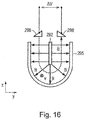
- magnetic field B passes laterally and radially downwardly from the pole piece 292 towards the magnetic material loop 295. Flow of water through the magnetic field filled space causes an electric field to be generated which is sensed by the electrodes 298.
- the flow meter sub-assembly need not be detachably mountable to the housing using a bayonet connector.
- Other forms for detachable connector for example similar to those used for detachable hosepipe connections, can be used.
- the flow meter sub-assembly can be permanently mounted.
- Multiple measurement electrodes can be used on the insertion element. These can either be connected in parallel subject to geometry, or they may simply be connected to additional electrode inputs in the electronics. This latter arrangement provides a means to manage severe non-uniformity of flow profile, by allowing arbitrary combinations of signals from multiple sets of distributed electrodes to be combined together in software to synthesize a flow-profile immune sensor. Other commonly-used electrode materials may be used, independent of the features of this invention.
- Magnetic field can be generated using remanent elements, conventional solenoids, or other bi-stable or rotating magnetic components.
- the operating mode of the meter (field vs. time) may be varied, independent of the core features of this invention.
- Soft magnetic parts may be made from electrical steel, soft ferrite, magnetic stainless steels, such as 9CR (available from Vacuumschmelze GmbH & Co. KG, Germany), Chrome Core 12FM, and the like. Soft magnetic parts can be made from non stainless steels or other corrodible materials, such as CoFe, provided they have a protective coating or employ some other way of avoiding rusting or other corrosion.
- Semi-hard part material (that is, the remanent elements) may comprise SENSORVAC (RTM) (available from Vacuumschmelze GmbH & Co. KG, Germany) or the like.
- RTM SENSORVAC
- Electrodes may be made from graphite, platinum, gold, silver/silver chloride, conductive plastic, stainless steel etc.
- Insulation may be formed from a plastic such as PPS, ABS or acrylic, glass, epoxy, paint, varnish, oxide, or a powder coat (for example polyester).
- a plastic such as PPS, ABS or acrylic, glass, epoxy, paint, varnish, oxide, or a powder coat (for example polyester).
- Parts of the sensor may be made from (non-magnetic) brass or 316L stainless, power-coated cast or ductile iron and/or (magnetic) magnetic stainless, such as 12FM (available from Ugitech).
- Any water compatible polymers including PPS, polyamide, polypropylene, may be used for wetted electrically and magnetically inert parts.
- Magnetic stainless steel can act both as a water ground and as a magnetic screen, and as the outer pole piece in an inner pole/outer pole geometry.
- Ground may be electrical safety ground continuity across the meter and/or electrical reference point connected to the electronics to provide immunity to common mode electrical interference.
Landscapes
- Physics & Mathematics (AREA)
- Fluid Mechanics (AREA)
- General Physics & Mathematics (AREA)
- Electromagnetism (AREA)
- Measuring Volume Flow (AREA)
Description
- The present invention relates to an electromagnetic flow sensor, to a sub-assembly which comprises a register and the electromagnetic flow sensor, and to an electromagnetic flow meter assembly comprising the sub-assembly and a housing through which water (or other conductive fluid) can flow.
- Battery-powered electromagnetic flow meters (which may also be referred to as "magnetic flow meters" or "mag meters") for residential water metering are known and examples include the iPERL (RTM) range of water meters available from Sensus Inc. Reference is also made to
WO 00/19174 A1 - Existing electromagnetic flow meters can suffer one or more limitations.
- First, many existing types of electromagnetic flow meter are not particularly suited to low-cost and/or high-volume manufacture. Typically, electromagnetic flow meters are needed in a range of different sizes for different sizes of pipes. However, many component parts of a typical electromagnetic flow meter, such as sensing electrodes, electromagnetic coils and the like, tend to depend on the size of the flow tube. Thus, a specific set of component parts is manufactured for each size of flow meter and each size of flow meter tends to have a different assembly line. This can increase manufacturing costs.
- Secondly, existing types of electromagnetic flow meter tend to have electromagnetic coils which are arranged around the outside of a plastic flow pipe. Thus, these types of flow meter may be prone to damage since they often used in situations where pipes are misaligned and, thus, are subjected to stress during fitting and use. As a result of being formed from plastic and being connected to metal pipes (which are generally more resilient to stress), these types of flow meter may crack. Furthermore, the electromagnetic coils are located further away from the flow channel which will result in a weaker magnetic field than a closer coil, thereby reducing sensitivity, or require more power to compensate and so increase power consumption of the flow meter.
- Thirdly, electromagnetic flow meters tend to be fitted in and around flow pipes. Thus, to discourage or prevent ingress of water from outside the flow meter into electrical parts of the flow meter (such as the coils and electrodes), the electrical parts are often encapsulated with a potting compound after the flow meter has been assembled.
-
US 5 325 728 A describes an electromagnetic flow meter for measuring the flow of blood through a conduit. Flow rate is measured by applying an electromagnetic field around the conduit, with the moving electrolytic blood inducing a current that is sensed by electrodes. The flow meter includes a substantially "E"-shaped magnetic core structure as well as an "E"-shaped hinged cover piece for defining a complete flux loop. In the circuitry, a floating ground arrangement is provided for enhancing the stability and sensitivity of the meter and to ensure appropriate patient isolation. A strong magnetic field, covering the sensing region and with little flux leakage, is alternately switched in polarity. The magnetic coil driver circuit employs an arrangement of switches for facilitating very fast polarity reversal. A two-level current source in the coil current driver greatly enhances the meter's efficiency and power dissipation characteristics. Extensive provisions, both electrical and mechanical, are made to reduce the effects of capacitive coupling, spurious induced currents, electromagnetic interference, and susceptibility to noise and external magnetic fields. A dual gated sample hold circuit samples the sensor signal during steady intervals. A second dual sample-and-hold averaging circuit minimizes the effects of base-line drift in the sense signal and low-frequency noise in the amplifier stage. The flow meter includes a two section error detection circuit which generates an error signal either when the flow signal exceeds power supply limits or when the rate of change of the flow signal exceeds a clinically reasonable rate. -
US 4 554 828 A describes a device for the magneto-inductive measuring of the flow rate of a liquid medium is disclosed wherein a cylindrical probe is immersed in a tube or in an open channel. The probe contains a cylindrical measuring channel through which flows the fluid to be measured. The probe includes a coil, which generates a magnetic field that extends through the measuring channel and whose axis is normal to the direction of fluid flow. Electrodes are mounted on the wall of the measuring channel, from which a voltage may be taken that is proportional to the flow rate of the fluid. - According to a first aspect of the present invention there is provided an electromagnetic flow sensor. The sensor comprises a body or frame, a passage through the body or frame, at least part of a magnetic circuit supported by the body or frame for directing a magnetic field across the passage and at least first and second electrodes supported by the body or frame. The first and second electrodes are arranged to sense a voltage in response to a conductive fluid (such as water) flowing through the passage. The at least part of the magnetic circuit comprises a central pole piece, and outer pole piece(s) extending around the central pole piece and the passage so as to serve as a magnetic screen from an external magnetic field. The passage has a central protrusion extending into and along the passage so as to present a 'U'-shaped profile to the flow of the conductive fluid of the conductive fluid, wherein the central protrusion is electrically insulated and includes the central pole piece.
- The magnetic circuit parts may be electrically insulated from the conductive fluid, for example by means of an insulating coating.
- At least a portion of the body or frame supporting the part of the magnetic circuit and the at least first and second electrodes may be configured to be insertable into a flow tube through a single aperture in the flow tube.
- The magnetic screen may comprise sufficient thickness of magnetic material to avoid saturation when a magnet of a strength specified by the Measuring Instruments Directive is placed against the meter.
- The body or frame may, in use, be in direct contact with the ionic fluid and the electrically conductive parts except the at least first and second electrodes are electrically insulated from the water.
- According to a second aspect of the present invention there is provided a sub-assembly comprising an electromagnetic flow sensor and a meter register. The electromagnetic flow sensor and the meter register form a single unit.
- The part of the magnetic circuit and the electrodes may be integrally formed in the meter register.
- According to a third aspect of the present invention there is provided an electromagnetic flow meter comprising a sensor.
- According to a fourth aspect of the present invention there is provided an electromagnetic flow meter comprising a tubular fluid housing having a fluid housing wall and a fluid housing aperture in the fluid housing wall, an optional conditioning tube(s) disposed within the fluid housing and having a water conditioning tube wall and a conditioning tube aperture in the conditioning tube wall and a sensor or a sub-assembly comprising a sensor, the sensor inserted in the tubular water housing so as to at least partially pass through the fluid housing aperture and to at least partially pass through the conditioning tube aperture.
- The sensor may be removably inserted in the tubular housing. The sensor, however, may be permanently mounted to the tubular housing.
- The tubular housing may take the form of a T-piece pipe.
- The meter may be a whole-flow flow meter.
- A meter may be configured such that a continuous electrical ground connection from one end of the meter to the other, and to the water, is formed by the main meter body.
- A meter body may be configured to provide an electrical reference point for an electronic module.
- Certain embodiments of the present invention will now be described, by way of example, with reference to the accompanying drawings, in which:
-
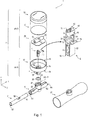
Figure 1 is an exploded perspective view of a flow meter assembly comprising a flow meter sub-assembly having an integrated flow measurement element which is removably insertable into a flow tube and which is capable of fitting a range of different flow tube diameters; -
Figure 2a is a schematic slightly-off side view of a flow meter sub-assembly inserted in a DN15 flow tube; -
Figure 2b is a schematic slightly-off end view of a flow meter sub-assembly inserted in a DN15 flow tube; -
Figure 2c is a transverse cross-sectional view of a flow meter sub-assembly inserted in a DN15 flow tube; -
Figure 2d is a longitudinal cross-sectional view of a flow meter sub-assembly inserted in a DN15 flow tube; -
Figures 3a is a schematic slightly-off side view of a flow meter sub-assembly inserted in a DN20 flow tube; -
Figure 3b is a schematic slightly-off end view of a flow meter sub-assembly inserted in a DN20 flow tube; -
Figure 3c is a transverse cross-sectional view of a flow meter sub-assembly inserted in a DN20 flow tube; -
Figure 3d is a longitudinal cross-sectional view of a flow meter sub-assembly inserted in a DN20 flow tube; -
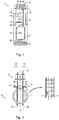
Figure 4 is a side view of a flow measurement element comprising a printed circuit board, electrodes, a magnetic circuit, a sense coil and an auxiliary ground electrode; -
Figure 5 is a cross-section view of a flow measurement element inserted in a DN15 flow tube and illustrates magnetic field lines and induced electric field resulting from a flow of water through the flow tube; -
Figure 6a is a perspective view of a flow measurement element with DN15 flow conditioner; -
Figure 6b is a side view of a flow measurement element with DN15 flow conditioner; -
Figure 7 is an end view of a flow measurement element in a DN20 flow tube; -
Figure 8a is a perspective view of a flow measurement element with DN20 flow conditioner; -
Figure 8b is a side view of a flow measurement element with DN20 flow conditioner; -
Figure 9 is a side view of a flow measurement element and DN50 flow conditioner; -
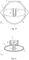
Figure 10 is an end view of a DN50 conditioning tube showing profile change from a round inlet and central location of flow measurement element; -
Figure 11 is a cross section through the DN50 flow tube taken along the line A-A' inFigure 9 showing mounting of a flow measurement element in the flow tube; -
Figure 12 is an end view of an insertion flow measurement element in a flow tube with printed circuit board electrodes, magnetic circuit, sense coil and auxiliary ground electrode and illustrates magnetic field lines and induced electric field resulting from a flow of water through the flow tube; -
Figure 13 is a side view of an insertion flow element in a flow tube; -
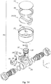
Figure 14 is an exploded perspective view of another flow meter assembly comprising a flow meter sub-assembly having an insert which houses a flow measurement element which is removably insertable into a flow tube and which is capable of fitting a range of different flow tube diameters; -
Figure 15a is perspective view of the insert shown inFigure 14 ; -
Figure 15b is an exploded perspective view of the insert shown inFigure 14 ; -
Figure 15c is a top plan view of the insert shown inFigure 14 ; -
Figure 15d is a side elevational view of the insert shown inFigure 14 ; -
Figure 15e is cross section of the insert shown inFigure 15d taken along the line C-C'; -
Figure 15f is a front elevational view of the insert shown inFigure 14 ; -
Figure 15g is cross section of the insert shown inFigure 15f taken along the line D-D'; and -
Figure 16 illustrates magnetic field generated by the magnetic circuit in the flow measurement element shown inFigure 14 and an electric field generated when water flows through the flow measurement element. - Referring to
Figures 1 and2a to 2d , a first flow meter assembly 1 (herein referred to simply as a "flow meter"), which is not part of the invention as defined by the claims. - The
flow meter 1 can be used for water metering using battery-powered electromagnetic sensing for residential commercial and industrial purposes. In particular, theflow meter 1 can be used as a battery-powered fiscal water meter meeting recognised international standards for water metering accuracy. - The first
flow meter assembly 1 includes a flow meter sub-assembly 2 (herein also referred to as a "flow meter unit") which comprises aregister 3 having an integrated insert 4 (or "plug") which comprises a flow measuring element 5 (herein also referred to as a "flow measurement element", "flow sensor" or simply "sensor") providing an electromagnetic flow sensor which is removably insertable into a generallytubular water housing 7 having aninner conditioning tube 7. - The
water housing 6 can have a nominal diameter of 20 mm, that is, it is a DN20 fitting (or the equivalent or corresponding NPS or American Standard sizes). However, as will be explained in more detail hereinafter, the plug 4 can be inserted into different sizes oftubular water housing 6, for example, DN15, DN50 and so on, so as to provide different sizes of flow meter (in other words, so as to provide water meters which can be used with different sizes of pipes). - Referring still to
Figures 1 and2a to 2d , theflow meter sub-assembly 2 includes ahousing 11 for theregister 3 which comprises a shallow plastic or metal cylindrical can 12 and a shallow transparent cap 13 (herein referred to as a "window"). Thehousing 11 has a diameter, d, of approximately 75 mm. - The register can 12 has a
bottom edge 14 and a top edge 15 (herein also referred to as the "top rim"), aside wall 16 running between the bottom andtop edges bottom end wall 17 having acentral aperture 18. Acollar 19, which is coaxial with theaperture 18, depends from thebottom end wall 17 and has inwardly projectingpins 20 providing a male part of abayonet connector 21. A depending 'U'-shaped plug 22 (or "insert"), also aligned with theaperture 18, depends from thebottom end wall 17. Theplug 22 comprises first and secondparallel plates 23, 24 (or "side walls") connected by abottom cross piece 25 thereby defining first and second open faces 26, 27 and apassage 28 between thefaces - Referring still to
Figures 1 and2a to 2d , theflow meter sub-assembly 2 includes a drive electronics module 29 (herein also referred to simply as the "electronics") and adisplay 30 which sits in the register can 12 under thewindow 13. Thedrive electronics module 29 includes a register printed circuit board (PCB) 31 which supports drive electronics components (not shown) and aAA battery 33 which is held in place byspring clip 34. - The register can 12 is filled with potting compound (not shown). The measuring
element 5 is insertably connected to aconnector 36 on the underside of theregister PCB 31 and encapsulated using, for example, the potting compound. - The
electronics module 29 is maintained in a dry environment using standard methods, such as, for example, potting, using a glass-metal construction, low water permeability plastics, desiccant and the like. - Referring still to
Figures 1 and2a to 2d and referring also toFigures 4 and 5 , the measuringelement 5 takes the form of an insertion electromagnetic flow sensor. - The measuring
element 5 includes first and second flat, rectangular plate-like parts part planar PCB 44 having a first face 46 ("inward face") and second face 48 ("outward face") running between first and second ends 50, 51 ("lower and upper ends") and between first andsecond edges 54, 55 ("forward and rear edges"). About two-thirds of the way between the lower and upper ends 50, 51, eachPCB 44 has aslot 58 running from theforward edge 54 towards, but not reaching, therear edge 55. - Each
PCB 44 supports first, second and thirdrectangular electrodes inward face 46. Theelectrodes lower end 50 and theslot 58. Thesecond electrode 61 is interposed between the first andthird electrodes - The
electrodes surface 46 of thecircuit board 44 using standard plating and etching processes. Theelectrodes - Multiple electrodes can be used, for example, to improve the flow measurement performance, to act as reference or bias electrodes and/or to detect when the sensor is full of water or not. In the illustrate embodiment not part of the invention as defined by the claims, a
single ground electrode 61 is used, which can be employed to bias electronics for the electrode inputs so that they are within an acceptable common mode input range. - Each
PCB 44 also supports asense coil 66 on the lower portion of itsinward face 46, which is used to measure the magnetic field B. Thesense coil 66 may comprise one or more loops which is connected to a set ofconnectors 68 at theupper end 51 of thesensor PCB 44 viaconductive tracks 70. - Each
PCB 44 supports a respective electrically-insulatedpole piece 72 on the lower portion of itsoutward face 48. Thepole pieces 72 are insulated, for example by painting, coating or encapsulating thepole pieces 72 with an insulating material (not shown) or by placing thepole pieces 72 such that surrounding plastic parts separate thepole pieces 72 away or keeps them sufficiently far from the water flow so that thepole pieces 72 do not short out induced emf. In use, the electrically-insulatedpoles pieces 72 are wetted. Eachpole piece 72 takes the form of a sheet, for example strip, or piece, for example a block or bar, of soft magnetic material, such as a high permeability electrical stainless steel, for example 430FR, which runs from thelower end 50 of thePCB 44 towards theupper end 51. When thepole piece 72 reaches theslot 58, it bends outwardly to form a narrow wing 74 (or "ledge"). - The
upper face 76 of thewing 74 supports one or more sheets, for example strips, orpieces 78 of remanent magnetic material. The remanent magnetic material is a semi-hard magnetic material, such as Vacuumschmelze SENSORVAC (RTM), Hitachi ZMG423 or MagneDur 20-4 The one or more remanentmagnetic parts 78 pass through adrive coil 79 and bridge the twoPCBs 44pole pieces 72. - The
pole pieces 72 are preferably made from permeable stainless steel, although other suitable soft magnetic materials may be used. This arrangement can avoid the need to pass magnetic flux through a pressure-withstanding flow tube wall. This can help to improve efficiency of field generation across the water for a given magnetic drive power. This can allow lower power consumption for a given flow sensitivity. This can also allow a wider variety of materials to be used to construct the flow tube wall. - The magnetic field is preferably generated using the remanent
magnetic element 78 operating at low frequency, such as 1 Hz, to help reduce or minimise power consumption and thus allow the sensors to be powered using abattery 33. - The
pole pieces 72 may be mounted on the measurement insert or insert-moulded into theflow tube 7. - Referring still to
Figures 1 and2a to 2d , thetubular water housing 6 comprises apipe wall 82 which runs between first and second open ends 83, 84 and provides a tubular space 85. Thehousing 6 also includes an opening 86 disposed midway between the first and second ends 83, 84 which is provided with a short,annular collar 87 upstanding from thepipe wall 82 and which has a pair of 'L'-shapedslots 88 recessed into the outer wall of thecollar 87 on opposite sides of thecollar 87 providing a female part of thebayonet connector 21. - The
flow meter sub-assembly 2 and thetubular water housing 6 are connected by thebayonet connector 21. Aseal 89, such as an 'O'-ring, sits on an annular shelf 90 within thecollar 87 and helps to provide a water-tight seal and so help to discourage or prevent water from escaping from thehousing 6. - The
tubular housing 6 may be fabricated from a wide range of materials including metals and plastics. The metals may be non-ferrous, such as bronze or brass, or magnetic materials such as ductile iron, and may coated with a suitable waterproof coating such as epoxy or powder coating to prevent corrosion. Thetubular housing 6 may be disposed within a tubular magnetic shield (not shown). The shield (not shown) may be formed from mild steel or other suitable material. The shield (not shown) may have plastic coating(s) (not shown), for example, for cosmetic appearance and/or for electrical insulation. - Referring still to
Figures 1 and2a to 2d and also toFigure 6a and 6b , theconditioning tube 7 comprises atube wall 91 which runs between first and second open ends 92, 93 and has an inner and outer wall surfaces 94, 95. Theinner wall surface 94 provides aflow passage 96. The profile of thepassage 96 generally narrows from thefirst end 92 of thetube 7 towards the middle 97, serving to accelerate the water velocity through the sensor, typically by a factor of 2 to 3, and hence increase the signal generates between the electrodes for a given volumetric flow rate. The profile of thepassage 96 in transverse cross sectional profile can also change from being circular or elliptical to being rectangular to match the dimensions of the flow measuring element. - In the middle 97 of the
tube 7, thetube wall 91 includes a longitudinally-orientated slot 98. The slot 98 has a profile and is dimensioned so as to receive theplug 22 and, thus, insert theflow measuring element 5 into theflow passage 96. Thetube wall 91 may include anotherslot 99 on the opposite side of thetube 7 so as to allow a distal end of theplug 22 to pass back out of the tube. - A single insertion element 4 is able to be used for a range of flow tube sizes.
- Referring in particular to
Figures 2a to 2d and5 , for the smallest size ofhousing 6, in this case DN15, the sensor element 4 is slightly oversized for the dimensions of the flow tube. This is accommodated by a bulge 100 (best shown inFigure 2d ) in theouter housing 6 so that the sensor 4 is symmetrically located. - Referring also to
Figures 6a and 6b , the only path for water through the meter is through the sensor element 4 and the flow-conditioning plastic inserts 7 are used to accelerate and decelerate the flow upstream and downstream to minimise non-recoverable head loss. - Referring in particular to
Figures 3a to 3d and7 , a DN20 meter follows a similar pattern, but in this case the sensing element 4 fits exactly to the bottom of the flow tube. In this case, the housing 6' is a sized for connection to DN20 fittings. - Referring to
Figures 8a and 8b , flow conditioning plastic parts 7' control the transition from a circular to an accelerated rectangular region and back to circular again. - In both the DN15 and DN20 meters, the rectangular
section flow tube - Larger sizes of meters require a different approach since it is not possible to pass the full flow volume of, for example a DN50 meter, through the small aperture of the insertion flow sensor.
- Referring to
Figures 9 ,10 and 11 , an arrangement by which this may be achieved is shown. The flow conditioning elements are arranged such that the insertion element 4 aperture remains central in the reduced aperture flow area so that flow profile effects, such as elbows and valves, have a minimal effect of accuracy. Theflow conditioning parts 7" are configured to maintain good flow profile immunity in these larger sizes. The signal-to-noise ratio of a larger-diameter meter should match that of the smaller sizes, if the flow conditioning elements are arranged to provide the same velocity acceleration as in the smaller sizes, whilst the power requirements to generate the magnetic field are the same as for the smaller diameter meters. - Referring to
Figures 12 and 13 , a second measuring element 104 is shown. The second flow measuring element 104 is similar to the first measuring element 5 (Figure 1 ) hereinbefore described and can be used as the measuring element in the flow meter assembly 1 (Figure 1 ) hereinbefore described. - The second flow measuring element 104 differs in that first and
second PCBs 144 sandwich a central element, for example in the form of a strip, of softmagnetic material 172 having first and secondopposite sides - Each
circuit board 144 has at least twoelectrodes electrodes - The magnetic circuit consists of an electrically-insulated generally rectangular outer section of soft
magnetic material 173 and the centralplanar pole piece 172 which is sandwiched between the twocircuit boards 144. These parts are preferably permeable stainless steel, coated with an insulating material such as PTFE, powder coat, epoxy, paint, varnish, or polymer. - The
field generating element 178 is located between theouter box 173 andcentral element 172. One or moreremanent elements 178, which can take the form or a strip, bar or other part with a suitable geometry, pass through thecoil 179. - The flow conditioning elements should be insulating and mate closely with the outer
magnetic circuit part 173 in order to avoid shorting out the electrode signal through additional paths through the water or where a conductive flow tube is used. The flow conditioning elements require an additional insulating plane in line with the centralmagnetic element 172 in order to avoid shorting out the signal around the sides of thecircuit boards 144. - There are
multiple measurement electrodes electrodes PCBs 144 can either be connected in anti-parallel subject to geometry, connected in series if the axial extents of the insulators and conditioning elements are long enough, or they may simply be connected to additional differential electrode inputs in the electronics. This latter arrangement provides a means to manage severe non-uniformity of flow profile, by allowing arbitrary combinations of signals from multiple sets of distributed electrodes to be combined together in software to synthesize a flow-profile immune sensor. - The exact position of the
electrodes circuit boards 144 may be altered to tune the response of the design to laminar versus turbulent flow, to minimise any change in sensitivity versus flow rate. - The second measuring element 104 can provide improved immunity to external magnetic fields. An additional external magnetic shield (not shown) can be omitted, if immunity to external fields is required by law (such as the EU Measuring Instruments Directive), regulatory authority, manufacturer, utility company or other relevant party. This is because the
outer box 173 can serve as a magnetic shield. - Referring to
Figure 14 , a second flow meter assembly 201 (herein referred to simply as a "flow meter") in accordance with the present invention is shown. - The second flow meter assembly 201 includes a
flow meter sub-assembly 202 which comprises a register 203 having an integrated insert 204 (or "plug") which comprises a flow measuring element 205 (herein also referred to as a "flow measurement element", "flow sensor" or simply "sensor") providing an electromagnetic flow sensor which is removably insertable into a generallytubular water housing 206 having an inner conditioning tube (not shown). - The second flow meter assembly 201 is similar to the first flow meter assembly 1 (
Figure 1 ). The second flow meter assembly 201 differs mainly in the configuration of theflow measuring element 205. - Referring still to
Figure 14 , the register 203 is similar to the register 3 (Figure 1 ) hereinbefore described. The register 203 includes a housing which comprises a metal cylindrical can 212 and a flattransparent window 213 provided with aperimeter window seal 208. The housing 211 has a diameter, d, of approximately 75 mm. - The housing 211 contains drive electronics 229 and a display 230 which are substantially the same or similar to those hereinbefore described and so will not be described again here in detail.
- As mentioned earlier, the second flow meter assembly 201 differs mainly from the first flow meter assembly 1 (
Figure 1 ) in the configuration of theflow measuring element 205. - In the first flow meter assembly 1 (
Figure 1 ), the first flow measuring element 5 (Figure 1 ) comprised flat, rectangular plate-like sensor parts 42, 43 (Figure 1 ) which define a channel between thesensor parts 42, 43 (Figure 1 ) which presents a vertically-orientated, rectangular profile to the flow of water. - The second flow measuring element 5 (
Figure 12 ), which is not part of the invention as defined by the claims, comprises two channels, each which presents a vertically-orientated, rectangular profile to the flow of water. Thus, each half can be thought of as a separate rectangular cell. The electronics could treat each half separately or join the electrodes together in series. - In the second flow meter assembly 201, the third
flow measuring element 205 defines a channel which presents a 'U'-shaped profile to the flow of water, as will now be described in more detail. - Referring also to
Figures 15a to 15g , theinsert 204 comprises abody 241 which is generally cylindrical in shape and symmetrical about a central, vertical plane (not shown). Theinsert body 241 has first and second ends 242, 243 (herein referred to as the "bottom" and "top" of the body respectively) andouter walls 244 running between the bottom 242 and top 243 of the insert. - The
insert body 204 comprises lower andupper portions internal floor 247. - The
lower body portion 245 of theinsert body 204 comprises a generally 'U'-shapedwall 248 comprising first and second flat side wall portions 249, 250 and a curved bottom wall portion 251. Thewall 248 extends between first and second ends 253, 254 (herein referred to as "front" and "back" respectively). Thewall 248 defines a cavity 252 (herein also referred to as "flow passage" or simply "passage"). Thelower body portion 245 includes front curtain-like wall 255 which extends approximately half way between thefloor 247 and the bottom 244. - The 'U'-shaped
wall 248 and the curtain-like wall 255 define first andsecond apertures like wall 255, thefirst aperture 256 is less tall than thensecond aperture 257. - A generally flat-sided, oval-shaped biscuit cutter-like frame 258 (herein also referred to as a "former") projects from an
inner face 259 of the curtain-like wall 255 through thecavity 252. At the top 260 of theframe 258, theframe 258 drops with two sets ofvertical walls upper channel 263 havingledges 264 and a narrowerlower channel 265 having a bottom 266, thereby forming a 'U'-shapedlower channel portion 267 and two, upper generally triangle-shapedchannel portions 268. The dropped portion of the frame 258 (i.e. thewalls ledges 264 and bottom 266) form a central protrusion which provides an insulating barrier. The bottom of theframe 258 drops below the lower edge of thewall 255 close to thebottom 269 of thecavity 252. - A generally
annular space 270 is defined between the inside of thebody wall 248 and the outside of theframe 258. - The
upper body portion 246 of theinsert body 204 includesannular wall 271 divided into lower and upperannular wall sections lower wall section 272 has smaller inner and outer diameters than theupper wall section 273 thereby defining inner andouter steps wall 271. Thelower wall section 272 includes a radially outwardly-projectingannular rib 276 which runs around the outside of thelower wall section 262 along its bottom edge. Theouter step 275 andrib 276 define anannular groove 277 which can accommodate an 'O'-ring 278. The upperannular wall section 273 is provided with a radially outwardly-projectinglip 279 having an inclined upper edge 280 and flat lower edge 281 thereby defining a barbed profile. - Referring still to
Figures 14 and15a to 15g , the measuringelement 205 is assembled within thebody 241 of theinsert 204, in particular, around theframe 258. - The
insert 204 includes amagnetic circuit 291 which includes a central element, for example a sheet, bar or other part with suitable geometry, of softmagnetic material 292, first and second elements of remanentmagnetic material 293, for example sheets, bars or other parts with suitable geometry, which run through anelectromagnetic coil 294 and a two-piece magnetic material loop 295 (or "yoke") comprising a generally 'U'-shapedportion 296 and acover portion 297. Thepole piece 292 comprises soft magnetic material. Thecentral element 292 provides a central magnetic pole. - The
pole piece 292 can be sandwiched between twoPCBs 244 which electrically insulate thepole piece 292. - The
insert 204 also includes an electric field measurement arrangement comprising first andsecond electrodes 298 and first and secondelectrode connecting rods 299. The connectingrods 299 andcoil connecting wires 300 are connected to aflexi connector 301. Theelectrodes 298 and electrode connecting rods preferably comprise graphite. - The
electrodes 298 are generally triangular prism shaped is disposed in the respective triangle-shapedchannel portions 268. Theelectrodes 298 may be other shapes, such as, for example, strips, bars, rods or the like. The connectingrods 299 pass through respective through holes (not shown) in the dividingfloor 247 and mate with blind holes (not shown) in therespective electrodes 298. - The
pole piece 292 is disposed in the lowerinner frame channel 265 and thecoil 294 is disposed in the upperinner frame channel 263. The two-piecemagnetic material loop 295 sits in theouter frame space 270. Theinsert 204 may be filled withpotting material 302. - Referring to
Figure 16 , in this arrangement, magnetic field B passes laterally and radially downwardly from thepole piece 292 towards themagnetic material loop 295. Flow of water through the magnetic field filled space causes an electric field to be generated which is sensed by theelectrodes 298. - It will be appreciated that various modifications may be made to the embodiments hereinbefore described. Such modifications may involve equivalent and other features which are already known in the design, manufacture and use of electromagnetic flow meter and component parts thereof and which may be used instead of or in addition to features already described herein. Features of one embodiment may be replaced or supplemented by features of another embodiment.
- The flow meter sub-assembly need not be detachably mountable to the housing using a bayonet connector. Other forms for detachable connector, for example similar to those used for detachable hosepipe connections, can be used. Moreover, the flow meter sub-assembly can be permanently mounted.
- Different geometries of flow conditioning elements are possible, particularly for the larger sizes. The typical lay lengths of the larger meters provide ample space to manage the flow profiles such that the insertion element itself sees the same flow rate regardless of upstream or downstream conditions.
- Multiple measurement electrodes can be used on the insertion element. These can either be connected in parallel subject to geometry, or they may simply be connected to additional electrode inputs in the electronics. This latter arrangement provides a means to manage severe non-uniformity of flow profile, by allowing arbitrary combinations of signals from multiple sets of distributed electrodes to be combined together in software to synthesize a flow-profile immune sensor. Other commonly-used electrode materials may be used, independent of the features of this invention.
- Magnetic field can be generated using remanent elements, conventional solenoids, or other bi-stable or rotating magnetic components. The operating mode of the meter (field vs. time) may be varied, independent of the core features of this invention.
- Soft magnetic parts (for example, the pole pieces) may be made from electrical steel, soft ferrite, magnetic stainless steels, such as 9CR (available from Vacuumschmelze GmbH & Co. KG, Germany), Chrome Core 12FM, and the like. Soft magnetic parts can be made from non stainless steels or other corrodible materials, such as CoFe, provided they have a protective coating or employ some other way of avoiding rusting or other corrosion.
- Semi-hard part material (that is, the remanent elements) may comprise SENSORVAC (RTM) (available from Vacuumschmelze GmbH & Co. KG, Germany) or the like.
- Electrodes may be made from graphite, platinum, gold, silver/silver chloride, conductive plastic, stainless steel etc.
- Insulation may be formed from a plastic such as PPS, ABS or acrylic, glass, epoxy, paint, varnish, oxide, or a powder coat (for example polyester).
- Parts of the sensor may be made from (non-magnetic) brass or 316L stainless, power-coated cast or ductile iron and/or (magnetic) magnetic stainless, such as 12FM (available from Ugitech). Any water compatible polymers, including PPS, polyamide, polypropylene, may be used for wetted electrically and magnetically inert parts.
- Magnetic stainless steel can act both as a water ground and as a magnetic screen, and as the outer pole piece in an inner pole/outer pole geometry. Ground may be electrical safety ground continuity across the meter and/or electrical reference point connected to the electronics to provide immunity to common mode electrical interference.
Claims (14)
- An electromagnetic flow sensor for an electromagnetic flow meter (201), the sensor comprising:a body (204) or frame;a passage (252) through the body or frame;at least part of a magnetic circuit (248, 295) supported by the body or frame for directing a magnetic field across the passage; andat least first and second electrodes (298) supported by the body or frame, the at least first and second electrodes arranged to sense a voltage in response to a conductive fluid flowing through the passage;wherein the at least part of the magnetic circuit comprises:a central pole piece (172; 292); andouter pole piece(s) (173; 295) extending around the central pole piece and the passage so as to serve as a magnetic screen from an external magnetic fieldcharacterised in thatthe passage has a central protrusion (261, 262, 264, 266) extending into and along the passage so as to present a 'U'-shaped profile to the flow of the conductive fluid, wherein the central protrusion is electrically insulated and includes the central pole piece.
- A sensor according to any preceding claim, wherein the magnetic circuit parts are electrically insulated from the conductive fluid.
- A sensor according to any preceding claim, wherein at least a portion of the body or frame supporting the part of the magnetic circuit and the at least first and second electrodes are configured to be insertable into a flow tube through a single aperture in the flow tube.
- A sensor according to any preceding claim, wherein the magnetic screen comprises sufficient thickness of magnetic material to avoid saturation when a magnet of a strength specified by the Measuring Instruments Directive is placed against the meter.
- A sensor according to any preceding claim, wherein the body or frame is, in use, in direct contact with the conductive fluid and the electrically conductive parts except the at least first and second electrodes are electrically insulated from the conductive fluid.
- A sub-assembly comprising:an electromagnetic flow sensor according to any preceding claim; anda meter register;
wherein the electromagnetic flow sensor and the flow sensor form a single unit. - A sub-assembly according to claim 6, wherein the part of the magnetic circuit and the electrodes are integrally formed in the meter register.
- An electromagnetic flow meter comprising:
a sensor according to any one of claims 1 to 5. - An electromagnetic flow meter comprising:a tubular fluid housing having a fluid housing wall and a fluid housing aperture in the fluid housing wall;optional conditioning tube disposed within the fluid housing and having a fluid conditioning tube wall and a conditioning tube aperture in the conditioning tube wall; anda sensor according to any one of claims 1 to 5 or a sub-assembly according to claim 6 or 7 comprising a sensor, the sensor inserted in the tubular fluid housing so as to at partially pass through the fluid housing aperture and to at least partially pass through the conditioning tube aperture.
- A meter according to claim 9, wherein the sensor is removably inserted in the tubular housing.
- A meter according to claim 9 or 10, wherein the tubular housing is a T-piece pipe.
- A meter according to any one of claims 8 to 11 which is a whole-flow flow meter.
- A meter according to any one of claims 8 to 12, wherein the meter body is configured to provide electrical safety ground continuity across the meter.
- A meter according to any one of claims 8 to 13, wherein the meter body is configured to provide an electrical reference point for an electronic module.
Applications Claiming Priority (4)
| Application Number | Priority Date | Filing Date | Title |
|---|---|---|---|
| GBGB1513271.5A GB201513271D0 (en) | 2015-07-28 | 2015-07-28 | Modular flow meter |
| GBGB1515159.0A GB201515159D0 (en) | 2015-08-26 | 2015-08-26 | Improved modular flow meter |
| EP16747581.3A EP3329220A1 (en) | 2015-07-28 | 2016-07-28 | Electromagnetic flow sensor |
| PCT/GB2016/052323 WO2017017463A1 (en) | 2015-07-28 | 2016-07-28 | Electromagnetic flow sensor |
Related Parent Applications (1)
| Application Number | Title | Priority Date | Filing Date |
|---|---|---|---|
| EP16747581.3A Division EP3329220A1 (en) | 2015-07-28 | 2016-07-28 | Electromagnetic flow sensor |
Publications (2)
| Publication Number | Publication Date |
|---|---|
| EP3435040A1 EP3435040A1 (en) | 2019-01-30 |
| EP3435040B1 true EP3435040B1 (en) | 2020-03-25 |
Family
ID=56567632
Family Applications (2)
| Application Number | Title | Priority Date | Filing Date |
|---|---|---|---|
| EP16747581.3A Withdrawn EP3329220A1 (en) | 2015-07-28 | 2016-07-28 | Electromagnetic flow sensor |
| EP18194819.1A Active EP3435040B1 (en) | 2015-07-28 | 2016-07-28 | Electromagnetic flow sensor |
Family Applications Before (1)
| Application Number | Title | Priority Date | Filing Date |
|---|---|---|---|
| EP16747581.3A Withdrawn EP3329220A1 (en) | 2015-07-28 | 2016-07-28 | Electromagnetic flow sensor |
Country Status (16)
| Country | Link |
|---|---|
| US (1) | US11054291B2 (en) |
| EP (2) | EP3329220A1 (en) |
| JP (1) | JP2018525626A (en) |
| KR (1) | KR20180044301A (en) |
| CN (1) | CN107923776B (en) |
| AU (1) | AU2016299404B2 (en) |
| BR (1) | BR112018001384A2 (en) |
| CA (1) | CA2992919A1 (en) |
| CL (1) | CL2018000239A1 (en) |
| CO (1) | CO2018000981A2 (en) |
| ES (1) | ES2796124T3 (en) |
| MX (1) | MX2018001099A (en) |
| RU (1) | RU2018106882A (en) |
| SA (1) | SA518390810B1 (en) |
| WO (1) | WO2017017463A1 (en) |
| ZA (1) | ZA201800603B (en) |
Families Citing this family (25)
| Publication number | Priority date | Publication date | Assignee | Title |
|---|---|---|---|---|
| DE102016123123A1 (en) * | 2016-11-30 | 2018-05-30 | Endress+Hauser Flowtec Ag | Magnetic-inductive flowmeter |
| DE102017112950A1 (en) * | 2017-06-13 | 2018-12-13 | Krohne Messtechnik Gmbh | Magnetic-inductive flowmeter and method for operating a magnetic-inductive flowmeter |
| IT201700112704A1 (en) * | 2017-10-06 | 2019-04-06 | Eltek Spa | HYDRAULIC CONTROL DEVICE FOR LIQUID DUCTED APPLIANCES OR SYSTEMS |
| IT201700112681A1 (en) * | 2017-10-06 | 2019-04-06 | Eltek Spa | HYDRAULIC CONTROL DEVICE FOR LIQUID CONDUCTOR EQUIPMENT AND SYSTEMS |
| IT201700112670A1 (en) * | 2017-10-06 | 2019-04-06 | Eltek Spa | SAFETY DEVICE AGAINST LIQUID LEAKS FOR LIQUID DUCTED HOUSEHOLD APPLIANCES |
| IT201800002751A1 (en) * | 2018-02-16 | 2019-08-16 | Eltek Spa | DETECTION AND / OR CONTROL DEVICE FOR LIQUID-CONDUCTED EQUIPMENT OR SYSTEMS |
| USD867913S1 (en) * | 2018-03-16 | 2019-11-26 | General Electric Company | Flow sensor |
| GB201814762D0 (en) * | 2018-09-11 | 2018-10-24 | Sentec Ltd | Insert electromagnetic flow sensor for centrifugal pump |
| US11029180B2 (en) * | 2018-10-16 | 2021-06-08 | Corey CRAIG | Fluid metering component and spraying apparatuses thereof |
| US11925949B1 (en) | 2018-10-16 | 2024-03-12 | Optix Technologies, LLC | Fluid metering component and spraying apparatus thereof |
| DE102018125865B4 (en) * | 2018-10-18 | 2022-12-22 | Krohne Ag | Electromagnetic flowmeters, magnetic circuit devices and method of manufacturing a magnetic circuit device |
| DE102018132600B4 (en) * | 2018-12-18 | 2024-02-22 | Endress+Hauser Flowtec Ag | Magnetic-inductive flow measuring probe and measuring point for determining a flow and/or an installation angle |
| US10718644B1 (en) * | 2019-01-03 | 2020-07-21 | Dwyer Instruments, Inc. | Sensor head for insertion electromagnetic flow meter |
| US11378429B2 (en) * | 2019-02-22 | 2022-07-05 | Onicon Incorporated | Insertion magnetic meters and methods |
| CN110231063A (en) * | 2019-05-30 | 2019-09-13 | 江阴市富仁高科股份有限公司 | A kind of gas flowmeter detecting oil gas |
| GB201910986D0 (en) * | 2019-08-01 | 2019-09-18 | Sentec Ltd | Insert electromagnetic flow sensor for centrifugal pump |
| GB201911971D0 (en) * | 2019-08-21 | 2019-10-02 | Sentec Ltd | Improved electrode |
| US11175169B2 (en) * | 2019-08-29 | 2021-11-16 | Sensus Spectrum, Llc | Systems for connecting a central module to a network and related connectors |
| CN110905483B (en) * | 2019-11-07 | 2023-03-21 | 西安康际石油科技有限公司 | Integrated flowmeter for microwave water content and flow of oil field |
| NL2024318B1 (en) * | 2019-11-27 | 2021-08-30 | Fnv Ip Bv | Electric field gradient sensor |
| CN112179430A (en) * | 2020-09-30 | 2021-01-05 | 湖南常德牌水表制造有限公司 | Ultrasonic water meter anti-interference protection device |
| EP3982090A1 (en) * | 2020-10-09 | 2022-04-13 | Husqvarna Ab | Metering console |
| KR20220060148A (en) | 2020-11-04 | 2022-05-11 | ㈜위드유 | Water cut meter using microwave resonance |
| EP4278156A1 (en) * | 2021-01-12 | 2023-11-22 | Micro Motion, Inc. | Interface with improved accessibility |
| KR20230112213A (en) | 2022-01-20 | 2023-07-27 | ㈜위드유 | System for verifying the accuracy of water cut meters |
Family Cites Families (18)
| Publication number | Priority date | Publication date | Assignee | Title |
|---|---|---|---|---|
| DE3236909A1 (en) * | 1982-10-06 | 1984-04-12 | Turbo-Werk Messtechnik GmbH, 5000 Köln | MEASURING DEVICE FOR INDUCTIVE MEASUREMENT OF THE FLOW SPEED OF LIQUID MEDIA |
| DE3501768A1 (en) | 1985-01-21 | 1986-07-24 | Danfoss A/S, Nordborg | ELECTROMAGNETIC FLOW METER |
| JPH01140021A (en) * | 1987-11-26 | 1989-06-01 | Yamatake Honeywell Co Ltd | Electromagnetic flowmeter |
| CN2115521U (en) | 1992-01-24 | 1992-09-09 | 天津市自动化仪表三厂 | Insert type electromagnetic flow sensor |
| US5325728A (en) * | 1993-06-22 | 1994-07-05 | Medtronic, Inc. | Electromagnetic flow meter |
| CN1067738C (en) * | 1996-12-19 | 2001-06-27 | 中国工程物理研究院应用电子学研究所 | Underground electromagnetic flowmeter |
| JP2969514B2 (en) * | 1997-08-27 | 1999-11-02 | 日本ピラー工業株式会社 | Mounting structure of sensor for fluid measurement |
| EP1125098B1 (en) * | 1998-09-29 | 2016-07-27 | Scientific Generics Limited | Magnetic flow meter |
| CN2449199Y (en) | 2000-11-21 | 2001-09-19 | 陈宝荣 | Intelligent electromagnetic flow meter |
| CN1299099C (en) * | 2001-02-06 | 2007-02-07 | 埃尔斯特计量有限公司 | Flowmeter |
| US6983661B2 (en) * | 2003-05-15 | 2006-01-10 | Endress + Hauser Flowtec Ag | Electromagnetic flow sensor |
| CN1712907A (en) * | 2005-07-13 | 2005-12-28 | 吉林大学 | Turbine electromagnetic flowmeter with low starting output volume |
| US7437945B1 (en) * | 2008-02-14 | 2008-10-21 | Murray F Feller | Magnetic flow probe |
| US20090205400A1 (en) * | 2008-02-16 | 2009-08-20 | Luther Donald Mcpeak | System and method for measuring fluid flow |
| US7779702B2 (en) * | 2008-11-03 | 2010-08-24 | Rosemount Inc. | Flow disturbance compensation for magnetic flowmeter |
| JP2012008108A (en) * | 2010-06-28 | 2012-01-12 | Toshiba Corp | Electromagnetic flow meter |
| RU2596863C2 (en) | 2010-08-03 | 2016-09-10 | ГОУЭНС Ли | Electromagnetic flow meter |
| CN102840356B (en) * | 2012-08-23 | 2013-11-13 | 杭州云谷科技有限公司 | Electromagnetic flow measurement and control integrated device |
-
2016
- 2016-07-28 JP JP2018504093A patent/JP2018525626A/en active Pending
- 2016-07-28 RU RU2018106882A patent/RU2018106882A/en not_active Application Discontinuation
- 2016-07-28 EP EP16747581.3A patent/EP3329220A1/en not_active Withdrawn
- 2016-07-28 WO PCT/GB2016/052323 patent/WO2017017463A1/en active Application Filing
- 2016-07-28 US US15/747,560 patent/US11054291B2/en active Active
- 2016-07-28 ES ES18194819T patent/ES2796124T3/en active Active
- 2016-07-28 KR KR1020187006043A patent/KR20180044301A/en unknown
- 2016-07-28 CN CN201680044465.4A patent/CN107923776B/en active Active
- 2016-07-28 EP EP18194819.1A patent/EP3435040B1/en active Active
- 2016-07-28 AU AU2016299404A patent/AU2016299404B2/en active Active
- 2016-07-28 CA CA2992919A patent/CA2992919A1/en not_active Abandoned
- 2016-07-28 MX MX2018001099A patent/MX2018001099A/en unknown
- 2016-07-28 BR BR112018001384A patent/BR112018001384A2/en not_active Application Discontinuation
-
2018
- 2018-01-25 SA SA518390810A patent/SA518390810B1/en unknown
- 2018-01-26 CL CL2018000239A patent/CL2018000239A1/en unknown
- 2018-01-29 ZA ZA2018/00603A patent/ZA201800603B/en unknown
- 2018-01-30 CO CONC2018/0000981A patent/CO2018000981A2/en unknown
Non-Patent Citations (1)
| Title |
|---|
| None * |
Also Published As
| Publication number | Publication date |
|---|---|
| CL2018000239A1 (en) | 2018-07-13 |
| KR20180044301A (en) | 2018-05-02 |
| CA2992919A1 (en) | 2017-02-02 |
| WO2017017463A1 (en) | 2017-02-02 |
| ZA201800603B (en) | 2019-07-31 |
| CO2018000981A2 (en) | 2018-06-12 |
| AU2016299404A1 (en) | 2018-02-15 |
| ES2796124T3 (en) | 2020-11-25 |
| US11054291B2 (en) | 2021-07-06 |
| JP2018525626A (en) | 2018-09-06 |
| EP3435040A1 (en) | 2019-01-30 |
| CN107923776B (en) | 2020-05-19 |
| AU2016299404B2 (en) | 2021-02-04 |
| MX2018001099A (en) | 2018-07-06 |
| SA518390810B1 (en) | 2021-09-05 |
| BR112018001384A2 (en) | 2018-09-11 |
| CN107923776A (en) | 2018-04-17 |
| RU2018106882A (en) | 2019-08-28 |
| US20180216978A1 (en) | 2018-08-02 |
| EP3329220A1 (en) | 2018-06-06 |
Similar Documents
| Publication | Publication Date | Title |
|---|---|---|
| EP3435040B1 (en) | Electromagnetic flow sensor | |
| US8826743B2 (en) | Magnetic inductive flow meter having magnetic poles distributing uniform magnetic field lines over the entire pole surface | |
| CA2994683C (en) | Inductive flow meter including extended magnetic pole pieces | |
| US20140083199A1 (en) | Magnetic flowmeter with multiple coils | |
| US4554828A (en) | Measuring device for the magneto-inductive measuring of the flow rate of a liquid medium | |
| US7272978B2 (en) | Magnetic-inductive flow meter with an electrically isolated measuring tube | |
| JP2002328052A (en) | Magnet guidance flowmeter and magnet guidance flow measuring method for fluid | |
| RU2431118C2 (en) | Electromagnetic flow meter of liquid metals | |
| CN211824561U (en) | Low-power consumption and wide-range electromagnetic water meter sensor | |
| WO2018100447A1 (en) | An attachable electromagnetic flowmeter | |
| EP4007893B1 (en) | Insert-type electromagnetic flow meter | |
| WO2018193294A1 (en) | An electromagnetic flowmeter | |
| CN211978009U (en) | Electromagnetic flowmeter assembly | |
| CN111771104A (en) | Electromagnetic flowmeter |
Legal Events
| Date | Code | Title | Description |
|---|---|---|---|
| PUAI | Public reference made under article 153(3) epc to a published international application that has entered the european phase |
Free format text: ORIGINAL CODE: 0009012 |
|
| STAA | Information on the status of an ep patent application or granted ep patent |
Free format text: STATUS: THE APPLICATION HAS BEEN PUBLISHED |
|
| AC | Divisional application: reference to earlier application |
Ref document number: 3329220 Country of ref document: EP Kind code of ref document: P |
|
| AK | Designated contracting states |
Kind code of ref document: A1 Designated state(s): AL AT BE BG CH CY CZ DE DK EE ES FI FR GB GR HR HU IE IS IT LI LT LU LV MC MK MT NL NO PL PT RO RS SE SI SK SM TR |
|
| STAA | Information on the status of an ep patent application or granted ep patent |
Free format text: STATUS: REQUEST FOR EXAMINATION WAS MADE |
|
| 17P | Request for examination filed |
Effective date: 20190711 |
|
| RBV | Designated contracting states (corrected) |
Designated state(s): AL AT BE BG CH CY CZ DE DK EE ES FI FR GB GR HR HU IE IS IT LI LT LU LV MC MK MT NL NO PL PT RO RS SE SI SK SM TR |
|
| GRAP | Despatch of communication of intention to grant a patent |
Free format text: ORIGINAL CODE: EPIDOSNIGR1 |
|
| STAA | Information on the status of an ep patent application or granted ep patent |
Free format text: STATUS: GRANT OF PATENT IS INTENDED |
|
| INTG | Intention to grant announced |
Effective date: 20190828 |
|
| GRAS | Grant fee paid |
Free format text: ORIGINAL CODE: EPIDOSNIGR3 |
|
| GRAJ | Information related to disapproval of communication of intention to grant by the applicant or resumption of examination proceedings by the epo deleted |
Free format text: ORIGINAL CODE: EPIDOSDIGR1 |
|
| GRAL | Information related to payment of fee for publishing/printing deleted |
Free format text: ORIGINAL CODE: EPIDOSDIGR3 |
|
| STAA | Information on the status of an ep patent application or granted ep patent |
Free format text: STATUS: REQUEST FOR EXAMINATION WAS MADE |
|
| INTC | Intention to grant announced (deleted) | ||
| GRAR | Information related to intention to grant a patent recorded |
Free format text: ORIGINAL CODE: EPIDOSNIGR71 |
|
| STAA | Information on the status of an ep patent application or granted ep patent |
Free format text: STATUS: GRANT OF PATENT IS INTENDED |
|
| GRAA | (expected) grant |
Free format text: ORIGINAL CODE: 0009210 |
|
| STAA | Information on the status of an ep patent application or granted ep patent |
Free format text: STATUS: THE PATENT HAS BEEN GRANTED |
|
| AC | Divisional application: reference to earlier application |
Ref document number: 3329220 Country of ref document: EP Kind code of ref document: P |
|
| AK | Designated contracting states |
Kind code of ref document: B1 Designated state(s): AL AT BE BG CH CY CZ DE DK EE ES FI FR GB GR HR HU IE IS IT LI LT LU LV MC MK MT NL NO PL PT RO RS SE SI SK SM TR |
|
| INTG | Intention to grant announced |
Effective date: 20200218 |
|
| REG | Reference to a national code |
Ref country code: GB Ref legal event code: FG4D |
|
| REG | Reference to a national code |
Ref country code: AT Ref legal event code: REF Ref document number: 1249085 Country of ref document: AT Kind code of ref document: T Effective date: 20200415 Ref country code: IE Ref legal event code: FG4D |
|
| REG | Reference to a national code |
Ref country code: DE Ref legal event code: R096 Ref document number: 602016032809 Country of ref document: DE |
|
| PG25 | Lapsed in a contracting state [announced via postgrant information from national office to epo] |
Ref country code: RS Free format text: LAPSE BECAUSE OF FAILURE TO SUBMIT A TRANSLATION OF THE DESCRIPTION OR TO PAY THE FEE WITHIN THE PRESCRIBED TIME-LIMIT Effective date: 20200325 Ref country code: NO Free format text: LAPSE BECAUSE OF FAILURE TO SUBMIT A TRANSLATION OF THE DESCRIPTION OR TO PAY THE FEE WITHIN THE PRESCRIBED TIME-LIMIT Effective date: 20200625 Ref country code: FI Free format text: LAPSE BECAUSE OF FAILURE TO SUBMIT A TRANSLATION OF THE DESCRIPTION OR TO PAY THE FEE WITHIN THE PRESCRIBED TIME-LIMIT Effective date: 20200325 |
|
| PG25 | Lapsed in a contracting state [announced via postgrant information from national office to epo] |
Ref country code: LV Free format text: LAPSE BECAUSE OF FAILURE TO SUBMIT A TRANSLATION OF THE DESCRIPTION OR TO PAY THE FEE WITHIN THE PRESCRIBED TIME-LIMIT Effective date: 20200325 Ref country code: HR Free format text: LAPSE BECAUSE OF FAILURE TO SUBMIT A TRANSLATION OF THE DESCRIPTION OR TO PAY THE FEE WITHIN THE PRESCRIBED TIME-LIMIT Effective date: 20200325 Ref country code: GR Free format text: LAPSE BECAUSE OF FAILURE TO SUBMIT A TRANSLATION OF THE DESCRIPTION OR TO PAY THE FEE WITHIN THE PRESCRIBED TIME-LIMIT Effective date: 20200626 Ref country code: SE Free format text: LAPSE BECAUSE OF FAILURE TO SUBMIT A TRANSLATION OF THE DESCRIPTION OR TO PAY THE FEE WITHIN THE PRESCRIBED TIME-LIMIT Effective date: 20200325 Ref country code: BG Free format text: LAPSE BECAUSE OF FAILURE TO SUBMIT A TRANSLATION OF THE DESCRIPTION OR TO PAY THE FEE WITHIN THE PRESCRIBED TIME-LIMIT Effective date: 20200625 |
|
| REG | Reference to a national code |
Ref country code: NL Ref legal event code: MP Effective date: 20200325 |
|
| REG | Reference to a national code |
Ref country code: LT Ref legal event code: MG4D |
|
| PG25 | Lapsed in a contracting state [announced via postgrant information from national office to epo] |
Ref country code: NL Free format text: LAPSE BECAUSE OF FAILURE TO SUBMIT A TRANSLATION OF THE DESCRIPTION OR TO PAY THE FEE WITHIN THE PRESCRIBED TIME-LIMIT Effective date: 20200325 |
|
| REG | Reference to a national code |
Ref country code: DE Ref legal event code: R082 Ref document number: 602016032809 Country of ref document: DE Representative=s name: VENNER SHIPLEY GERMANY LLP, DE Ref country code: DE Ref legal event code: R082 Ref document number: 602016032809 Country of ref document: DE Representative=s name: VENNER SHIPLEY LLP, DE |
|
| PG25 | Lapsed in a contracting state [announced via postgrant information from national office to epo] |
Ref country code: SK Free format text: LAPSE BECAUSE OF FAILURE TO SUBMIT A TRANSLATION OF THE DESCRIPTION OR TO PAY THE FEE WITHIN THE PRESCRIBED TIME-LIMIT Effective date: 20200325 Ref country code: IS Free format text: LAPSE BECAUSE OF FAILURE TO SUBMIT A TRANSLATION OF THE DESCRIPTION OR TO PAY THE FEE WITHIN THE PRESCRIBED TIME-LIMIT Effective date: 20200725 Ref country code: CZ Free format text: LAPSE BECAUSE OF FAILURE TO SUBMIT A TRANSLATION OF THE DESCRIPTION OR TO PAY THE FEE WITHIN THE PRESCRIBED TIME-LIMIT Effective date: 20200325 Ref country code: RO Free format text: LAPSE BECAUSE OF FAILURE TO SUBMIT A TRANSLATION OF THE DESCRIPTION OR TO PAY THE FEE WITHIN THE PRESCRIBED TIME-LIMIT Effective date: 20200325 Ref country code: LT Free format text: LAPSE BECAUSE OF FAILURE TO SUBMIT A TRANSLATION OF THE DESCRIPTION OR TO PAY THE FEE WITHIN THE PRESCRIBED TIME-LIMIT Effective date: 20200325 Ref country code: PT Free format text: LAPSE BECAUSE OF FAILURE TO SUBMIT A TRANSLATION OF THE DESCRIPTION OR TO PAY THE FEE WITHIN THE PRESCRIBED TIME-LIMIT Effective date: 20200818 Ref country code: EE Free format text: LAPSE BECAUSE OF FAILURE TO SUBMIT A TRANSLATION OF THE DESCRIPTION OR TO PAY THE FEE WITHIN THE PRESCRIBED TIME-LIMIT Effective date: 20200325 Ref country code: SM Free format text: LAPSE BECAUSE OF FAILURE TO SUBMIT A TRANSLATION OF THE DESCRIPTION OR TO PAY THE FEE WITHIN THE PRESCRIBED TIME-LIMIT Effective date: 20200325 |
|
| REG | Reference to a national code |
Ref country code: AT Ref legal event code: MK05 Ref document number: 1249085 Country of ref document: AT Kind code of ref document: T Effective date: 20200325 |
|
| REG | Reference to a national code |
Ref country code: ES Ref legal event code: FG2A Ref document number: 2796124 Country of ref document: ES Kind code of ref document: T3 Effective date: 20201125 |
|
| REG | Reference to a national code |
Ref country code: DE Ref legal event code: R097 Ref document number: 602016032809 Country of ref document: DE |
|
| PG25 | Lapsed in a contracting state [announced via postgrant information from national office to epo] |
Ref country code: DK Free format text: LAPSE BECAUSE OF FAILURE TO SUBMIT A TRANSLATION OF THE DESCRIPTION OR TO PAY THE FEE WITHIN THE PRESCRIBED TIME-LIMIT Effective date: 20200325 Ref country code: AT Free format text: LAPSE BECAUSE OF FAILURE TO SUBMIT A TRANSLATION OF THE DESCRIPTION OR TO PAY THE FEE WITHIN THE PRESCRIBED TIME-LIMIT Effective date: 20200325 |
|
| PLBE | No opposition filed within time limit |
Free format text: ORIGINAL CODE: 0009261 |
|
| STAA | Information on the status of an ep patent application or granted ep patent |
Free format text: STATUS: NO OPPOSITION FILED WITHIN TIME LIMIT |
|
| PG25 | Lapsed in a contracting state [announced via postgrant information from national office to epo] |
Ref country code: MC Free format text: LAPSE BECAUSE OF FAILURE TO SUBMIT A TRANSLATION OF THE DESCRIPTION OR TO PAY THE FEE WITHIN THE PRESCRIBED TIME-LIMIT Effective date: 20200325 Ref country code: PL Free format text: LAPSE BECAUSE OF FAILURE TO SUBMIT A TRANSLATION OF THE DESCRIPTION OR TO PAY THE FEE WITHIN THE PRESCRIBED TIME-LIMIT Effective date: 20200325 |
|
| REG | Reference to a national code |
Ref country code: CH Ref legal event code: PL |
|
| 26N | No opposition filed |
Effective date: 20210112 |
|
| REG | Reference to a national code |
Ref country code: BE Ref legal event code: MM Effective date: 20200731 |
|
| PG25 | Lapsed in a contracting state [announced via postgrant information from national office to epo] |
Ref country code: LU Free format text: LAPSE BECAUSE OF NON-PAYMENT OF DUE FEES Effective date: 20200728 Ref country code: LI Free format text: LAPSE BECAUSE OF NON-PAYMENT OF DUE FEES Effective date: 20200731 Ref country code: CH Free format text: LAPSE BECAUSE OF NON-PAYMENT OF DUE FEES Effective date: 20200731 |
|
| PG25 | Lapsed in a contracting state [announced via postgrant information from national office to epo] |
Ref country code: SI Free format text: LAPSE BECAUSE OF FAILURE TO SUBMIT A TRANSLATION OF THE DESCRIPTION OR TO PAY THE FEE WITHIN THE PRESCRIBED TIME-LIMIT Effective date: 20200325 Ref country code: BE Free format text: LAPSE BECAUSE OF NON-PAYMENT OF DUE FEES Effective date: 20200731 |
|
| PG25 | Lapsed in a contracting state [announced via postgrant information from national office to epo] |
Ref country code: IE Free format text: LAPSE BECAUSE OF NON-PAYMENT OF DUE FEES Effective date: 20200728 |
|
| PG25 | Lapsed in a contracting state [announced via postgrant information from national office to epo] |
Ref country code: TR Free format text: LAPSE BECAUSE OF FAILURE TO SUBMIT A TRANSLATION OF THE DESCRIPTION OR TO PAY THE FEE WITHIN THE PRESCRIBED TIME-LIMIT Effective date: 20200325 Ref country code: MT Free format text: LAPSE BECAUSE OF FAILURE TO SUBMIT A TRANSLATION OF THE DESCRIPTION OR TO PAY THE FEE WITHIN THE PRESCRIBED TIME-LIMIT Effective date: 20200325 Ref country code: CY Free format text: LAPSE BECAUSE OF FAILURE TO SUBMIT A TRANSLATION OF THE DESCRIPTION OR TO PAY THE FEE WITHIN THE PRESCRIBED TIME-LIMIT Effective date: 20200325 |
|
| PG25 | Lapsed in a contracting state [announced via postgrant information from national office to epo] |
Ref country code: MK Free format text: LAPSE BECAUSE OF FAILURE TO SUBMIT A TRANSLATION OF THE DESCRIPTION OR TO PAY THE FEE WITHIN THE PRESCRIBED TIME-LIMIT Effective date: 20200325 Ref country code: AL Free format text: LAPSE BECAUSE OF FAILURE TO SUBMIT A TRANSLATION OF THE DESCRIPTION OR TO PAY THE FEE WITHIN THE PRESCRIBED TIME-LIMIT Effective date: 20200325 |
|
| PGFP | Annual fee paid to national office [announced via postgrant information from national office to epo] |
Ref country code: IT Payment date: 20230720 Year of fee payment: 8 Ref country code: GB Payment date: 20230727 Year of fee payment: 8 Ref country code: ES Payment date: 20230804 Year of fee payment: 8 |
|
| PGFP | Annual fee paid to national office [announced via postgrant information from national office to epo] |
Ref country code: FR Payment date: 20230725 Year of fee payment: 8 Ref country code: DE Payment date: 20230727 Year of fee payment: 8 |