CN1299099C - Flowmeter - Google Patents
Flowmeter Download PDFInfo
- Publication number
- CN1299099C CN1299099C CNB028011015A CN02801101A CN1299099C CN 1299099 C CN1299099 C CN 1299099C CN B028011015 A CNB028011015 A CN B028011015A CN 02801101 A CN02801101 A CN 02801101A CN 1299099 C CN1299099 C CN 1299099C
- Authority
- CN
- China
- Prior art keywords
- cylindrical shell
- housing
- fluid
- flowmeter
- flowline
- Prior art date
- Legal status (The legal status is an assumption and is not a legal conclusion. Google has not performed a legal analysis and makes no representation as to the accuracy of the status listed.)
- Expired - Fee Related
Links
Images


Classifications
-
- G—PHYSICS
- G01—MEASURING; TESTING
- G01F—MEASURING VOLUME, VOLUME FLOW, MASS FLOW OR LIQUID LEVEL; METERING BY VOLUME
- G01F15/00—Details of, or accessories for, apparatus of groups G01F1/00 - G01F13/00 insofar as such details or appliances are not adapted to particular types of such apparatus
- G01F15/18—Supports or connecting means for meters
-
- G—PHYSICS
- G01—MEASURING; TESTING
- G01F—MEASURING VOLUME, VOLUME FLOW, MASS FLOW OR LIQUID LEVEL; METERING BY VOLUME
- G01F1/00—Measuring the volume flow or mass flow of fluid or fluent solid material wherein the fluid passes through a meter in a continuous flow
- G01F1/56—Measuring the volume flow or mass flow of fluid or fluent solid material wherein the fluid passes through a meter in a continuous flow by using electric or magnetic effects
- G01F1/58—Measuring the volume flow or mass flow of fluid or fluent solid material wherein the fluid passes through a meter in a continuous flow by using electric or magnetic effects by electromagnetic flowmeters
-
- G—PHYSICS
- G01—MEASURING; TESTING
- G01F—MEASURING VOLUME, VOLUME FLOW, MASS FLOW OR LIQUID LEVEL; METERING BY VOLUME
- G01F15/00—Details of, or accessories for, apparatus of groups G01F1/00 - G01F13/00 insofar as such details or appliances are not adapted to particular types of such apparatus
- G01F15/14—Casings, e.g. of special material
-
- G—PHYSICS
- G01—MEASURING; TESTING
- G01F—MEASURING VOLUME, VOLUME FLOW, MASS FLOW OR LIQUID LEVEL; METERING BY VOLUME
- G01F15/00—Details of, or accessories for, apparatus of groups G01F1/00 - G01F13/00 insofar as such details or appliances are not adapted to particular types of such apparatus
- G01F15/18—Supports or connecting means for meters
- G01F15/185—Connecting means, e.g. bypass conduits
Abstract
An electromagnetic flow meter is configured as an insert for insertion into an in-situ housing connected in a flow line. This can enable a body previously installed for use with an insert of a mechanical flow meter to be adapted for use with an insert of an electromagnetic flow meter without having to disconnect the body from a mains supply.
Description
Technical field
The present invention relates to a kind of on-mechanical formula flowmeter, relate to a kind of electromagnetic flowmeter in a preferred embodiment, specifically, relate to and a kind ofly mainly be designed for commercial and the flowmeter of network monitor application and the method that this flowmeter is installed, but do not get rid of other.
Background technology
The monitoring of ensemble stream scale is used for the big current of water system management and business accounting purpose.An example of ensemble stream scale is our H4000 (HELIX 4000) Woltmann type instrument, wherein the current of admitting from the main line source of supply rotate rotor in measuring chamber, and the revolution counter calculates the winding number of rotor so that cubing value by the water of instrument is provided.The H4000 instrument places between flanged upstream and downstream part of supply pipe, makes that the current in the pipe directly flow through instrument.This flowmeter generally is referred to as " through-flow " instrument.For the ease of safeguarding, comprise that the measuring mechanism of rotor, measurement chamber and register can be pulled down from body, this body has the flange end that is connected in the main line source of supply, so that the similar mechanism of new pre-calibration can easily and promptly be installed in the body.
This " mechanical type " flowmeter can stand the wearing and tearing of one or more moving components of instrument.Any liability fraying is in the measuring accuracy variation that makes by the water yield of instrument.The coil that the mechanical flow table also tends to be overhang damages.As a result, the serviceable life of this instrument is quite short.
The electromagnetism instrument can not stand the problem of mechanical wear.Yet a problem of known electromagnetic flowmeter is that their tendency is heavy device, needs basic structure example as the outside that the coil that produces and measuring equipment attach to pipeline, measures mobility status in this pipeline.This may limit the suitable ability of electromagnetic flowmeter in the application of the lower space preciousness of flow rate.In addition, the maintenance of flowmeter may be main task, need remove the basic pipe portion section of working together with relevant coil and instrumentation.And, cross that basic pipeline produces that uniform magnetic field may need lot of energy and may be inaccessible.
Summary of the invention
In its preferred embodiment at least, the present invention manages to solve these and other problems.
On the one hand, the invention provides a kind of on-mechanical formula flowmeter, it comprises: housing, and this housing can be connected in the flowline in the following manner, and promptly the fluid that flows in this flowline is through this housing; Non-mechanical self-charge type flow measurement cylindrical shell is used for measuring the flow of this flowline, and this cylindrical shell can be able to be inserted in the housing when being formed at housing and being located in the flowline with pulling down, and this cylindrical shell has and makes fluid to be measured flow through wherein path.
In addition, above-mentioned electromagnetic flowmeter is configured to insert the form of the plug-in unit in this flowline and comprises the flow measurement conduit, is used for crossing this flow measurement conduit and produces the device in magnetic field and be used for deriving device through the measured value of the rate of flow of fluid of this flow measurement conduit from the voltage of inducting in the magnetic field of the fluid that flows through this flow measurement conduit.
Electromagnetic flowmeter is operated by following steps, that is, cross measuring guide and produce the voltage that the water that flows in magnetic field and the detected catheter is inducted, and the speed of mobile water is relevant in the magnitude of induced potential and the conduit.When instrument does not have moving component and the solid that do not overhang when influencing, its serviceable life can be above 20 years.Electromagnetic flowmeter also tends to have bigger measurement range than mechanical flow table.This electromagnetic flowmeter is disclosed in our No. 98/49528, the International Patent Application WO, and its content is incorporated herein by reference.
So far also do not attempt to replace the through-flow instrument of mechanical type with the through-flow instrument of electromagnetism of open type among the WO 98/49528, because this will be time-consuming, new electromagnetic flowmeter is pulled down and installed to the through-flow instrument of whole mechanical type that therefore will comprise the flange body that is connected on the main line source of supply is arm and a leg.
By being the plug-in unit that is used for being connected to the housing on the main line source of supply with the electromagnetic flowmeter body plan, this plug-in unit that just is used in the mechanical type instrument can easily and promptly be replaced, so that convert this instrument to precision higher and more durable electromagnetic flowmeter.
Plug-in unit preferably includes the flow measurement conduit, be used to cross the device that conduit produces magnetic field, and a device, and being used for derives measured value by the rate of fluid flow of conduit from the voltage of inducting in the magnetic field of the fluid that flows through conduit.
In a preferred embodiment, this plug-in unit comprises and is used to make the deflection of segment fluid flow stream to leave the device of conduit.This makes the Fluid Volume that flows through conduit can be restricted to amount in the measurement range of instrument, and most of fluid deflector leaves conduit.Preferably, this inflector assembly comprises at least one passage.This passage or each passage preferably extend around this conduit.This can help the size of this plug-in unit or each plug-in unit is reduced to minimum, so that be fitted in the housing.
Preferably, this plug-in unit is shaped so that this at least one passage to be provided.This can be provided conduit, generation device, inflector assembly and this at least one passage by single plug-in unit.
Preferably, this passage or each passage are limited by the outside surface of plug-in unit at least in part.This can simplify the manufacturing of plug-in unit.Preferably, plug-in unit is shaped so that be provided at a pair of this passage that extends around its each side.This passage or each passage preferably include the exit portion of an intake section that shrinks and an expansion.When conduit generally has the exit portion of an intake section that shrinks and an expansion, mainly, advantageously make each channel formation in a similar fashion in order to reduce the interval between the electrode that is used for detecting the voltage that the fluid that flows through conduit inducts.This can help the fluid stream by each passage is remained on a speed, this speed is proportional with the speed of the fluid stream that passes through conduit, make flow measurements proportional with rate of fluid flow by instrument, and can before flowing out, the fluid stream that leaves conduit can be reconfigured with fluid stream from each passage from housing, have minimum turbulent flow.
In a further advantageous embodiment, this instrument comprises the additional plug-in unit that is used for fluid stream is introduced conduit.This can make the mouth of conduit have the shape different with inlet.Should preferably include the sleeve in cross section so that fluid stream is introduced in the conduit by additional plug-in unit with contraction.
The present invention expands to aforesaid electromagnetic flowmeter, and it comprises the housing that is connected in the flowline, and this plug-in unit inserts in this housing.
This housing preferably has coaxial with its outlet basically inlet.This conduit is preferably coaxial with entrance and exit.
The present invention also provides a kind of method that aforesaid electromagnetic flowmeter is installed, and it comprises with these one or more plug-in units replaces the cylindrical shell that is installed in the housing that is connected in the flowline.
On the other hand, the invention provides a kind of cylindrical shell that can insert flow duct, this cylindrical shell has one and limits the through hole of flow channel, and the measuring apparatus that is used for measuring the fluid stream of through hole.
In a kind of advantageous applications, this instrument is an electromagnetic flowmeter, and measuring apparatus comprises a device that produces, and the fluid that is used to cross by through hole produces magnetic field; And sensing electrode, be used for the electromotive force that the fluid of sensing by through hole produces.
By this way, not a section of around pipeline, building the ensemble stream scale or must replace pipeline, but can simply the electromagnetic flowmeter cylindrical shell be inserted in the pipeline, do not increase the size of pipeline basically with flowmeter.And, because through hole has the size littler than pipeline, thus the flowing velocity by flowmeter greater than ducted flowing velocity, this can cause improved measuring accuracy.
Cylindrical shell preferably is arranged in the housing of fluid impervious.
This housing can have the size that occupies predetermined standard-sized pipeline.For example, the external dimensions of housing can be arranged to can get out patchhole in this pipeline in the pipeline of the circle of the standard that is fitted in or square-section.
More preferably, this piping arrangement becomes to insert pipeline and inserts in the housing, this pipeline inserts housing and comprises first and second coupling parts so that connect with corresponding upstream and downstream flow duct, and the instrument patchhole, and this cylindrical shell that comprises flowmeter can insert this instrument and insert in the hole.
In yet another aspect, the invention provides a kind of fluid metering instrument, it comprises:
Pipeline inserts housing, and this pipeline inserts housing and comprises first and second coupling parts so that connect with corresponding upstream and downstream flow duct, and the instrument patchhole, and this cylindrical shell that comprises flowmeter can insert this instrument and insert in the hole; And
The measuring apparatus that insertable cylindrical shell, this insertable cylindrical shell have the through hole that limits flow channel and be used for measuring the fluid stream of through hole.
A kind of preferred application is an electromagnetic flowmeter.Yet cylinder assembly can be used to comprise other flow metering equipment, for example mechanical flow table or ultrasonic flowmeter or other flowmeters.
In yet another aspect, the invention provides and a kind of flowmeter is installed in ducted method, this method comprises:
Housing is installed in the pipeline, and this housing has the opening that is arranged to admit the cylindrical shell that comprises flowmeter; And
The cylindrical shell that will comprise flowmeter is installed in the housing.
At related aspect, the invention provides a kind of flowmeter that is used for the fluid stream of measuring channel, this flowmeter comprises:
The metering body that comprises a housing, this housing comprise one and are arranged to measure the on-mechanical formula flowmeter that metering body fluid on every side flows; And
Be used for the metering body is installed in the erecting device of fluid path.
According to a preferred embodiment, the invention provides a kind of flowmeter that is used for the fluid stream of measuring channel, this flowmeter comprises:
The metering body that comprises a housing, this housing comprise device and the electromotive force sensing electrode that produces the field; And
Be used for the metering body is installed in the erecting device of fluid path.
Therefore, by gauge assembly being installed in the pipeline in " from inside to outside (inside-out) " structure, the size of flowmeter can reduce greatly.
Preferably, the metering body is fairshaped, and equally preferably, the metering body is a fluid-tight.In preferred construction, the metering body be the elongation and erecting device be arranged to like this, make axis of elongation be arranged essentially parallel to fluid flow path.
Preferably, the size of metering body is selected like this, makes the not interference of the existence of metered body basically of fluid stream perhaps to make the metering body limit fluid stream.In most of the cases, the cross section surface that this means the metering body should be basically less than the pipeline that the metering body wherein will be installed, or enough big (promptly, how much little inner section unlike pipeline is), make fluid stream be limited by (for example annular) gap between the outer surface of the surface, inside of pipeline and metering body.Mobile not layering strictly, but preferably measuring body forms like this, and near the feasible layering basically metering body at least of flowing is so that can obtain reliable measured value.
Advantageously, in one embodiment, erecting device comprises a flange, and this flange arrangement becomes to be clipped between the adjacent ribs of the pipe sections in the pipeline.This provides structure compact especially and that can insert easily.
Preferably, the metering body is in the center is installed on pipeline.
In an especially preferred embodiment, installation component comprises a flange, and this flange has that be used for will the device that aligns with pipeline axial of metering body.Preferably, alignment means comprises at least one teat, and preferred a plurality of teats, this teat are arranged to engage with grip bolt when flange rotates with respect to bolt.Therefore, the outside of flange preferably includes a series of local spiral section, the quantity of spiral section is corresponding to the quantity of grip bolt, for example 4, be preferably at least 3, minimum diameter is less than the diameter between the bolt, and maximum gauge makes the outside that has a flange keep the position against bolt greater than the diameter between the bolt.Under the situation of the flange that is used for larger-diameter pipeline, this pipeline can have a large amount of bolts, and teat only can be arranged to and a certain proportion of bolted joints.And the teat of bolted joints between, the outside should preferably have portion's section of circular.
Aspect a kind of method, the invention provides and a kind of flowmeter is installed in method in the pipeline, this method comprises:
The adjacent separating part of pipeline is set and mounting flange is clipped between the adjacent section of flange, internal flow meter is installed on this mounting flange.
As similar alternative arrangements, flowmeter can be installed in the cylindrical shell.This cylindrical shell can directly insert in the pipeline or in the housing, this case design becomes to keep this pipeline and is connected with the remainder of pipeline.
On the other hand, the invention provides a kind of non-mechanical self-charge type flow measurement cylindrical shell that is used for measuring the flow of flowline, this flowline comprises housing, the fluid that flows in flowline is through this housing, can be able to insert in the housing when wherein this cylindrical shell is formed at housing and is located in the flowline with pulling down, this cylindrical shell comprises can make fluid to be measured flow through wherein path, be used to cross the device that this path produces magnetic field, and be used for deriving device through the measured value of the rate of flow of fluid of this path from the voltage of inducting in the magnetic field of the fluid that flows through this path.
Description of drawings
Referring now to accompanying drawing, only preferred feature of the present invention is described by example, wherein:
Fig. 1 is the skeleton view of embedded mechanical flow table;
Fig. 2 to 5 is skeleton views, and the installation steps of first embodiment of electromagnetic flowmeter are described;
Fig. 6 illustrates second embodiment of electromagnetic flowmeter;
Fig. 7 is the skeleton view of the 3rd embodiment;
Fig. 8 is a skeleton view, represents the details of self-centering clamped flanges;
Fig. 9 is the planimetric map of the 3rd embodiment;
Figure 10 is the sectional view of the 3rd embodiment; And
Figure 11 is the perspective illustration of the inserted cylindrical shell of a fourth embodiment in accordance with the invention;
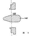
Figure 12 is the front view of the embodiment of Figure 11;
Figure 13 is the cross section by the B-B line of Figure 12; And
Figure 14 is the cross section by the C-C line of Figure 12;
Figure 15 is a decomposition view, represents the interior details of the metering body of third and fourth embodiment;
Figure 16 is the perspective illustration of inserted cylindrical shell according to a fifth embodiment of the invention;
Figure 17 is the synoptic diagram of the embodiment of Figure 16, the expression interior details;
Figure 18 represents by the cross section of the A-A line of Figure 17 interior details to be described;
Figure 19 is the cross section by the B-B line of Figure 17, and the convergent situation of through hole of the upstream and downstream of measuring position is described;
Figure 20 represents the skeleton view according to the inserted cylindrical shell of another embodiment;
(cross section) side view of the cylindrical shell of Figure 21 presentation graphs 2; And
Figure 22 represents the cross section by the A-A line of Figure 21.
Embodiment
Fig. 1 is the skeleton view of the example of the embedded flowmeter of mechanical type.Example shown in Fig. 1 is our H4000 (HELIX 4000) Woltmann type instrument, wherein the current of admitting from the main line source of supply rotate rotor in measuring chamber, and calculate the winding number of rotor so that be provided at the cubing value of the water that flows in the main line source of supply.
This instrument comprises body 10, and it has coaxial flange end 12,14, is used for connecting between the flange end of corresponding pipe sections entering the main line supply line.As clearlying show that among Fig. 2, this figure is typical mechanical flow table, measuring mechanism particularly including rotor, measure chamber, revolution counter and register, this measuring mechanism is housed within the plug-in unit 16 in the body 10 that can insert instrument.This makes that plug-in unit 16 can be replaced by the plug-in unit of new pre-calibration when finish the serviceable life of instrument, and will not be connected with the disconnection of main line source of supply by body 10.
Referring now to the installation of Fig. 2 to 5 description according to the electromagnetic flowmeter of the first embodiment of the present invention.
At first, refer again to Fig. 2, plug-in unit 16 is pulled down from the body 10 of mechanical type flowmeter.With reference now to Fig. 3,, in this first embodiment, plug-in unit 16 is replaced by three plug-in units 18,20 of electromagnetic flowmeter and 22.Plug-in unit 18 comprises flow measurement conduit 24.Conduit 24 comprises nonmagnetic, non-conduction, the impermeable pipe of treated for example plastic material, so that make it not be subjected to the influence of the seepage of water under pressure.Pipe has the cross section that is essentially rectangle at the place, end of its inlet 26 and outlet 28, the end of these entrance and exits is determined the flow rate of fluid by instrument by shrinking the center section that part (convergence) and expansion (dispersing) synthesizes the square-section by the center section of this square-section.The shape of conduit 24 is decided to be like this, has obtained uniform flow profile by center section for the fluid flow rate of certain limit in the conduit, and the pressure that leaves the fluid of conduit in the exit changes minimum.The pair of electrodes housing is arranged in the conduit, and an electrode is set in each electrode shell, makes electrode be arranged to cross orthogonally the flow direction and and the magnetic field orthotropic of the fluid in this mobile pipe.
Plug-in unit 18 also comprises the device that is used to cross conduit generation magnetic field.In this embodiment, this generation device comprises first and second pole pieces so that cross measuring guide guiding alternating magnetic field.The field coil 30 that each pole piece is used to generation magnetic field in pole piece surrounds, and the return path 32 that is used for magnetic flux is arranged between the pole piece of upper and lower.
Plug-in unit 18 also comprises a device, so that the voltage that magnetic field induced from the fluid that flows through conduit is derived the measured value of fluid by the flow rate of conduit.This device is arranged on inlet 18 shell 40 inside, and comprises circuit so that calculate flow rate by the voltage that electrode detected, by the details of magnetic this voltage of inducting in fluid.The other details of this circuit is included in No. 98/49528, our aforesaid International Application No. WO.Shell 40 can comprise display.
As shown in Figure 3, the shape in the hole of conduit 24 is different with the shape of the inlet 42 of the flange end 12 of body 10.In order to guide fluid from 42 inflow catheters 24 that enter the mouth, the plug-in unit 20 of shrinkage sleeve form inserted in the inlet 42 in case the guiding fluid from the inlet inflow catheter.The similar plug-in unit 22 of expansion form of sleeve inserts in the outlet of flange portions 14 so that the guiding fluid flows to outlet from conduit.
For electromagnetic flowmeter is installed, as shown in Figure 4, will overlap the entrance and exit that tubular plug-in unit 20,22 inserts the flange portion 12,14 of body 10 at first respectively.Then plug-in unit 18 is inserted in the body, make that conduit 24 and entrance and exit are coaxial, resulting electromagnetic flowmeter is shown among Fig. 5.The measured value and the rate of fluid flow in the main line source of supply of the rate of fluid flow by conduit 24 are proportional, and therefore the circuit of this instrument can be calibrated, and makes display indicate the volume by the fluid of instrument.
Fig. 6 has represented second embodiment according to electromagnetic flowmeter of the present invention.This second embodiment and first embodiment are similar, and wherein plug-in unit 50 inserts in the body 10, and this plug-in unit comprises flow measurement conduit 24, generation device, let-off gear(stand) and display 52.Yet in this second embodiment, plug-in unit 50 is cylinder-shaped, and this cylindrical shell has accommodated flow measurement conduit, generation device, let-off gear(stand).For cost being reduced to minimum, the service part that is used for the electromagnetic flowmeter of local metrology applications can form the basis of cylinder-shaped plug-in unit 50.In this embodiment, the outside surface that makes cylinder-shaped plug-in unit 50 is shaped so that be limited to the passage 60 that extends around the conduit 24 with the inside surface of body 10, make and have only the fluid from inlet 42 of part to flow to, and remaining fluid circulation is to leaving conduit and the outlet in flange portion 14 into conduit.As shown in Figure 6, each passage 60 comprises the intake section of contraction and the exit portion of expansion.In operation, the most of fluid flow that enters instrument is crossed passage 60 and is turned to and leave conduit 24, makes to enter the Fluid Volume of measuring guide within the normal measurement range of instrument.When conduit has contraction and expansion,, each passage 60 is shaped mainly in order to reduce the interval between the electrode so that the voltage that generates in the fluid of conduit is flow through in detection.This can help the fluid stream by each passage is remained on a speed, this speed is proportional with the rate of fluid flow by conduit 24, make flow measurements proportional with rate of fluid flow by instrument, and can have minimum turbulent flow before the outlet outflow of body 10, leaving the fluid stream of conduit 24 and reconfiguring from each passage 60 fluid stream.As among first embodiment, the circuit of instrument can be calibrated, and makes display indicate the volume by the fluid of instrument.
As mentioned above, the present invention can make the mechanical flow table easily and promptly replaced by electromagnetic flowmeter.With mechanical flow epiphase ratio, electromagnetic flowmeter can be through not frayed, and can not be subjected to the influence of suspended solid, and therefore have long serviceable life.Another advantage of the present invention is not need to replace body 10 so that electromagnetic flowmeter is installed.Therefore, the installation of electromagnetic flowmeter is convenient to carry out, because do not need body is not connected with the disconnection of main line source of supply.In addition, the initial capitalization of the body 10 of mechanical type instrument and its installation are kept getting off, because body 10 does not go out of use.
In the above description, with reference to H4000 mechanical type instrument.Yet, should be appreciated that the present invention is not limited to only replace with electromagnetic flowmeter the instrument of this particular type, and it is applicable to and replaces all types of mechanical type instrument that wherein measuring mechanism inserts body, or otherwise is arranged in body.
In order to summarize foregoing, be a plug-in unit with the electromagnetic flowmeter body plan, be used for inserting in the housing in place that is connected flowline.This can make previous installation can be suitable for using with the plug-in unit of electromagnetic flowmeter with the body of the plug-in unit that is used for the mechanical flow table, is not connected and will body do not disconnect with the main line source of supply.
With reference now to Fig. 7-10,, now the 3rd embodiment will be described.Metering body 140 comprises coil and the sensing electrode (not shown) that produces the field.This body overhangs in the hole 120 of installing component 122, and this installing component utilizes 3 symmetrically arranged poles 126 to comprise a flange.This flange has four teat 128a, 128b, 128c, 128d, and these teats extend to big relatively radius with the form of spiral generally from relatively little radius, and when flange rotated, the part of teat can contact with erection bolt thus.
A coil that is used for producing and the wiring of sensing electrode are directed to the outside by the passages of one or more installation poles 126, and are connected to conventional flowmeter opertaing device.
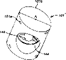
With reference to figure 11-14, show the 4th embodiment.
In the 4th embodiment, used similarly " from inside to outside " flowmeter.Yet the installation component that is used for this flowmeter comprises cylindrical shell 101 ', and this cylindrical shell is formed by upstream housing 101a and downstream housing 101b in this embodiment.This defines through hole 144, has population 130 and outlet 132.Flowmeter metering body 140 overhangs in this through hole.Unshowned sealing ring can be installed between two housing parts.Flowmeter metering body comprises the device of the generation field in the flowmeter metering body 140, and has the electromotive force sensing electrode on the outside of flowmeter metering body 140.Therefore, the flowing velocity of institute's sensing is the speed of the fluid that flows in the annular space between flowmeter body 140 and housing 101 ' inside.
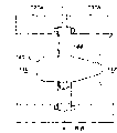
With reference to Figure 15, will explain the inner structure of metering body 140.Same or similar structure can be used with erecting device or other mounting structures of arbitrary embodiment.Metering body 140 has two electrodes 202 (one of them only is shown) on the opposite side of body, so that sensing crosses the electromotive force that fluid produces.The other electrode 204 that the upstream extremity of body (here) installs at the center is set to ground-electrode or ground reference electrode.When erecting device does not make fluid ground connection (for example under the situation of the cylindrical shell of making by plastic material; Particularly advantageous structure comprises the ground-electrode of installing at the center substantially in plastics meterings body and the fluid), this provide ground reference system aspect be useful especially.Magnetic circuit 206 is set limits coil space 208, the coil that produces the field twines (for the sake of clarity, coil itself is not shown among Figure 15) in this space.
Should be appreciated that, can make the remodeling of various details.Specifically, can change mounting structure to be suitable for various conduits, important principle is that flowmeter is installed in the conduit, and fluid flows through rather than flow through flowmeter around.For example, metering body even can be installed on the conventional pipeline reel is although this has reduced to have the advantage of compact metering body certainly.Diameter is that the metering body dimension of the magnitude of a centimetre or two centimetres is possible, and can obtain significant advantage under the situation of little metering body.The metering body can be advantageously generated by plastic material most.Yet this principle can be used for big many instrument, and this instrument is used to install in-line, and diameter is up to one meter or even bigger.In the latter case, owing to do not need wherein to be assembled with the big reel of instrument, thus can save widely, and power requires also can reduce.Under the situation of the instrument of macropore, specifically, this instrument does not need to install individually, but can be installed on the mobile jib movably in some cases.
Now the 5th embodiment will be described.
With reference to figure 16-19, cylindrical shell has the housing 312 of mounting flange and fluid impervious.One magnetic circuit 320 is arranged in the housing of fluid impervious, and it has coil 322a, 322b.Electrode 324 also is installed in the housing and gives prominence to so that contact with fluid.The either side of housing metering through hole 334 is provided with the ingate 330 of convergent and the outlet opening 332 of convergent.
Produce the coil of field and electrode is connected to flowmeter in normal mode opertaing device.
Under specific situation, the metering through hole can have the square-section, and can be bigger.In specific application, single coil can only be set to produce the field.
Figure 20-22 has represented a preferred embodiment.The cylindrical shell 401 that these accompanying drawings are represented is similar to the cylindrical shell shown in Figure 11.Cylindrical shell 401 has a hole 402, and fluid can be moving by this orifice flow.Hole 404 is arranged in the cylindrical shell and (is in the middle position by the roof of cylindrical shell 401 in Figure 20), so that admit the metering housing 406 with slender body.Corresponding hole or groove 408 are arranged in the diapire of cylindrical shell, also are used for admitting metering housing 406 (Figure 21 and 22), therefore measure body and extend perpendicular to the direction that flows through hole 402.Metering housing 406 can have the cylindrical portion section, but preferably as shown in 410 among Figure 20, it has fairshaped profile.The metering housing also can be columniform so that insert cylindrical shell 401, and wedge-shaped body or similarity piece be attached to the cylindrical metering housing 406 that inserts after the cylindrical shell, so that form the composite structure with streamlined section.
Shown in Figure 20-22, do not provide the metering conduit.Fluid flows around the metering body.
Disclosed each feature can be independently or provide in the mode of any suitable combination in instructions and/or claims and the accompanying drawing.Specifically, the feature of dependent claims can be combined in it not in the claim of subordinate.
Claims (20)
1. on-mechanical formula flowmeter, it comprises:
Housing, this housing can be connected in the flowline in the following manner, and promptly the fluid that flows in this flowline is through this housing;
Non-mechanical self-charge type flow measurement cylindrical shell, be used for measuring the flow of this flowline, can be able to be inserted in the described housing when described cylindrical shell is formed at this housing and is located in this flowline, and described cylindrical shell has and makes fluid to be measured flow through wherein path with pulling down.
2. flowmeter according to claim 1 is characterized in that, the measurement component fluid on every side that described cylindrical shell is arranged to this cylindrical shell of energy measurement flows, and described flowmeter comprises that also one is used for this measurement component is installed in the installation portion of this flowline.
3. flowmeter according to claim 2, it is characterized in that, this cylindrical shell comprises a generation device and electromotive force sensing electrode, described generation device is used for producing magnetic field at the measurement component fluid on every side of this cylindrical shell, and described electromotive force sensing electrode is used for the electromotive force that the fluid of sensing around this measurement component inducted.
4. according to the described flowmeter of one of claim 1 to 3, it is characterized in that this cylindrical shell is a fluid-tight.
5. according to claim 2 or 3 described flowmeters, it is characterized in that this installation portion comprises this cylindrical shell is installed in erecting device in this flowline that described erecting device has alignment means, is used to make this cylindrical shell to align vertically with described flowline.
6. according to claim 2 or 3 described flowmeters, it is characterized in that this installation portion comprises flange, this flange is arranged to be clipped between the adjacent flange of the duct section in this flowline.
7. according to the described flowmeter of one of claim 1 to 3, it is characterized in that this housing comprises first and second coupling parts, be used for connecting that this housing also comprises the patchhole of admitting this cylindrical shell with corresponding upstream and downstream duct section.
8. flowmeter according to claim 2 is characterized in that, this installation portion is positioned at this cylindrical shell on the center flow axis of described flowline.
9. flowmeter according to claim 1 is characterized in that, this cylindrical shell be elongation and install in the following manner, promptly axis of elongation is arranged essentially parallel to fluid flow direction.
10. according to the described flowmeter of one of claim 1 to 3, it is characterized in that the outlet of this housing and the inlet of this housing are coaxial basically.
11. non-mechanical self-charge type flow measurement cylindrical shell that is used for measuring the flow of flowline, described flowline comprises housing, the fluid that flows in described flowline is through this housing, when being formed at this housing and being located in this flowline, can be able to insert in the described housing wherein said cylindrical shell with pulling down, described cylindrical shell comprises can make fluid to be measured flow through wherein path, be used to cross the device that this path produces magnetic field, and be used for deriving device through the measured value of the rate of flow of fluid of this path from the voltage of inducting in the magnetic field of the fluid that flows through this path.
12. cylindrical shell according to claim 11 is characterized in that, this cylindrical shell comprises and is used to make segment fluid flow to depart from out the inflector assembly of this path through this housing.
13. cylindrical shell according to claim 12 is characterized in that, this inflector assembly comprises at least one passage.
14. cylindrical shell according to claim 13 is characterized in that, described at least one passage extends around this path.
15. cylindrical shell according to claim 14 is characterized in that, described at least one passage is defined by the outside surface of this cylindrical shell at least in part.
16., it is characterized in that described at least one passage has the intake section of contraction and the exit portion of expansion according to claim 13 or 14 described cylindrical shells.
17. cylindrical shell according to claim 16 is characterized in that, the profile of described path is similar with described at least one passage and become to shrink expanded configuration.
18. cylindrical shell according to claim 11 is characterized in that, also comprises being used for plug-in unit that fluid is introduced this path or drawn from this path.
19. cylindrical shell according to claim 18 is characterized in that, described plug-in unit comprises sleeve, and described sleeve has the circulation area of shrinking or expanding.
20. cylindrical shell according to claim 11 is characterized in that, described cylindrical shell is used for replacing the mechanical flowmeter cylindrical shell that is installed in the housing that is connected in flowline.
Applications Claiming Priority (6)
| Application Number | Priority Date | Filing Date | Title |
|---|---|---|---|
| GB0102941A GB2376529B (en) | 2001-02-06 | 2001-02-06 | Electromagnetic flow meter |
| GB0102941.2 | 2001-02-06 | ||
| GB0117292.3 | 2001-07-16 | ||
| GB0117291.5 | 2001-07-16 | ||
| GB0117291A GB0117291D0 (en) | 2001-07-16 | 2001-07-16 | Insertable flowmeter |
| GB0117292A GB0117292D0 (en) | 2001-07-16 | 2001-07-16 | Insertable flowmeter |
Publications (2)
| Publication Number | Publication Date |
|---|---|
| CN1460175A CN1460175A (en) | 2003-12-03 |
| CN1299099C true CN1299099C (en) | 2007-02-07 |
Family
ID=27256066
Family Applications (1)
| Application Number | Title | Priority Date | Filing Date |
|---|---|---|---|
| CNB028011015A Expired - Fee Related CN1299099C (en) | 2001-02-06 | 2002-02-05 | Flowmeter |
Country Status (9)
| Country | Link |
|---|---|
| US (1) | US7213467B2 (en) |
| EP (1) | EP1377800A1 (en) |
| JP (1) | JP2004520590A (en) |
| CN (1) | CN1299099C (en) |
| AU (1) | AU2002228232B2 (en) |
| BR (1) | BR0204017A (en) |
| CA (1) | CA2437628A1 (en) |
| IL (1) | IL152129A0 (en) |
| WO (1) | WO2002063250A1 (en) |
Families Citing this family (23)
| Publication number | Priority date | Publication date | Assignee | Title |
|---|---|---|---|---|
| GB2440963B (en) | 2006-08-18 | 2011-06-08 | Abb Ltd | Flow meter |
| GB2440964B (en) * | 2006-08-18 | 2011-08-10 | Abb Ltd | Flow meter |
| DE102007019610A1 (en) * | 2007-04-24 | 2008-10-30 | Endress + Hauser Flowtec Ag | Device for attaching a measuring or display unit to an object |
| CN101339060B (en) * | 2007-07-03 | 2010-06-23 | 上海星空自动化仪表有限公司 | Heavy caliber electrical flow meter for user to send it to be checked |
| GB2463488A (en) * | 2008-09-12 | 2010-03-17 | Elster Metering Ltd | A bidirectional flow meter |
| AU2010100111A4 (en) | 2009-11-12 | 2010-03-11 | Tushar Vatturkar | Flow Meters |
| US7886616B1 (en) | 2009-11-17 | 2011-02-15 | Hoffer Flow Controls, Inc. | In-line flow meter |
| US8166828B2 (en) * | 2010-08-06 | 2012-05-01 | Ecolab USA, Inc. | Fluid flow meter |
| JP6131277B2 (en) | 2012-02-28 | 2017-05-17 | ノーマ・ユー・エス・ホールディング・リミテッド・ライアビリティ・カンパニーNorma U. S. Holding Llc | Automotive selective contact reduction (SCR) system sensor holder and assembly |
| CN102636224B (en) * | 2012-05-11 | 2014-02-19 | 沈阳北星仪表制造有限公司 | Intelligent photoelectric magnetic flow meter |
| CN102778901A (en) * | 2012-08-02 | 2012-11-14 | 昆山旭虹精密零组件有限公司 | Petroleum flow control system |
| US9046396B2 (en) * | 2013-03-15 | 2015-06-02 | Dieterich Standard, Inc. | Process variable measurement using universal flow technology connection platform |
| US9151648B2 (en) * | 2013-03-15 | 2015-10-06 | Dieterich Standard, Inc. | Process variable measurement using primary element connection platform |
| CN103822675A (en) * | 2014-02-26 | 2014-05-28 | 中国科学院合肥物质科学研究院 | Novel electrode liquid metal electromagnetic flowmeter |
| DE102014113406A1 (en) * | 2014-09-17 | 2016-03-17 | Endress + Hauser Flowtec Ag | Magnetic-inductive flowmeter with insert |
| RU2018106882A (en) | 2015-07-28 | 2019-08-28 | Сентек Лтд | ELECTROMAGNETIC FLOW SENSOR |
| CN105806439A (en) * | 2016-05-05 | 2016-07-27 | 孟书芳 | Fixing base for ultralow-flow-velocity gas turbine flowmeter |
| GB2555003B (en) * | 2016-09-23 | 2022-07-06 | Blue White Ind Ltd | Flow sensor devices and systems |
| CN108955786B (en) * | 2017-05-23 | 2021-08-10 | 爱知时计电机株式会社 | Flow meter |
| MX2021008511A (en) | 2019-02-22 | 2021-08-19 | Onicon Incorporated | Improved insertion magnetic meters and methods. |
| TWI730810B (en) * | 2020-06-15 | 2021-06-11 | 桓達科技股份有限公司 | Electronic water meter |
| CN112833966B (en) * | 2020-12-28 | 2023-12-08 | 博锐格科技温州有限公司 | Underground layered tubule flowmeter and flow test method thereof |
| CN116929481B (en) * | 2023-09-18 | 2024-01-02 | 浙江蓝宝石仪表科技有限公司 | Buried flow metering device and monitoring method thereof |
Citations (9)
| Publication number | Priority date | Publication date | Assignee | Title |
|---|---|---|---|---|
| US4125019A (en) * | 1977-06-16 | 1978-11-14 | Monitek, Inc. | Probe type electromagnetic flow meter with debris shedding capability |
| US4459858A (en) * | 1981-09-18 | 1984-07-17 | Marsh-Mcbirney, Inc. | Flow meter having an electromagnetic sensor probe |
| US4554828A (en) * | 1982-10-06 | 1985-11-26 | Turbo-Werk Messtechnik Gmbh | Measuring device for the magneto-inductive measuring of the flow rate of a liquid medium |
| US4614113A (en) * | 1985-04-01 | 1986-09-30 | Mueller Co. | Water meter service installation |
| US4679442A (en) * | 1984-12-26 | 1987-07-14 | Kabushiki Kaisha Toshiba | Electromagnetic flow meter |
| US4911018A (en) * | 1988-02-23 | 1990-03-27 | Hartman Doanld R | Flow meter bracket |
| JPH02103418A (en) * | 1988-10-12 | 1990-04-16 | Toshiba Corp | Insertion type electromagnetic flowmeter |
| CN2202916Y (en) * | 1994-05-24 | 1995-07-05 | 田红良 | Transducer for plug type electromagnetic flowmeter |
| JPH09145437A (en) * | 1995-11-17 | 1997-06-06 | Kubota Corp | Inserting bar type electromagnetic flowmeter |
Family Cites Families (26)
| Publication number | Priority date | Publication date | Assignee | Title |
|---|---|---|---|---|
| US1817617A (en) | 1929-04-02 | 1931-08-04 | Nolde & Horst Co | Stretching machine for stockings |
| US2187914A (en) | 1938-08-05 | 1940-01-23 | Nebel Knitting Company | Hosiery testing apparatus |
| US2706402A (en) | 1952-05-14 | 1955-04-19 | Sr Gaither M Jones | Apparatus for determining the fitting characteristics of an item of hosiery |
| US3444728A (en) | 1967-02-14 | 1969-05-20 | Charles W Burns | Device for testing the stretch of fabric samples |
| US3471068A (en) | 1968-08-26 | 1969-10-07 | Us Industries Inc | Device for inspecting panty hose |
| BE759519A (en) * | 1969-11-28 | 1971-04-30 | Schlumberger Instrumentation | TURBINE VOLUMETRIC FLOW SENSOR |
| DE2224416C3 (en) | 1971-09-15 | 1975-06-19 | Cluett, Peabody & Co., Inc., New York, N.Y. (V.St.A.) | Apparatus for testing and recording elongation characteristics of extensible fabrics |
| DE3434068A1 (en) | 1984-09-17 | 1986-03-27 | Gerald 8960 Kempten Mauerhofer | Stretch-dimension tester for hosiery articles |
| GB8726924D0 (en) | 1987-11-18 | 1987-12-23 | Brown Boveri Kent Ltd | Number wheel counters |
| US5168146A (en) * | 1989-11-09 | 1992-12-01 | Marshall John D | Bi-directional snap-action register display mechanism |
| EP0471865B1 (en) | 1990-08-20 | 1996-05-15 | Oval Engineering Co., Ltd. | Positive displacement flowmeter |
| JPH04145437A (en) | 1990-10-08 | 1992-05-19 | Konica Corp | Production of waterless planograph |
| US5094110A (en) | 1990-11-16 | 1992-03-10 | Sara Lee Corporation | Cross stretch measuring system |
| US5235860A (en) | 1991-12-19 | 1993-08-17 | Sara Lee Corp. | Band stretch measuring system |
| US5659740A (en) | 1992-04-30 | 1997-08-19 | Olympus Optical Co., Ltd. | Information service system using unity code |
| JPH06211323A (en) | 1992-11-30 | 1994-08-02 | Olympus Optical Co Ltd | Physical distribution control system |
| US5605739A (en) | 1994-02-25 | 1997-02-25 | Kimberly-Clark Corporation | Nonwoven laminates with improved peel strength |
| US5944237A (en) | 1996-05-09 | 1999-08-31 | Spotless Plastics Pty. Ltd. | Method and system for color coding sizes of garments |
| JPH1161635A (en) | 1997-08-12 | 1999-03-05 | Dan:Kk | Apparatus for measuring size of elongation of fiber product |
| US6493678B1 (en) | 1998-05-22 | 2002-12-10 | Connectrix Systems, Inc. | Method, apparatus and system for merchandising related applications |
| JP3220692B2 (en) | 1999-10-20 | 2001-10-22 | 洋左右 前嶋 | Automatic cloth sorting device |
| US6381510B1 (en) | 1999-11-19 | 2002-04-30 | Eruggallery.Com | Methods and apparatus for facilitating electronic commerce in area rugs |
| US6665577B2 (en) | 2000-12-20 | 2003-12-16 | My Virtual Model Inc. | System, method and article of manufacture for automated fit and size predictions |
| US6793650B2 (en) | 2001-12-14 | 2004-09-21 | Kimberly-Clark Worldwide, Inc. | Disposable training pant designed specifically for late stage toilet training |
| US6949089B2 (en) | 2001-12-19 | 2005-09-27 | Kimberly-Clark Worldwide, Inc. | Method of providing a series of disposable absorbent articles to consumers |
| US8715257B2 (en) | 2001-12-28 | 2014-05-06 | Kimberly-Clark Worldwide, Inc. | Ratio of absorbent area to outer peripheral area for disposable absorbent articles |
-
2002
- 2002-02-05 JP JP2002562949A patent/JP2004520590A/en active Pending
- 2002-02-05 BR BR0204017-4A patent/BR0204017A/en not_active Application Discontinuation
- 2002-02-05 US US10/468,258 patent/US7213467B2/en not_active Expired - Fee Related
- 2002-02-05 CA CA002437628A patent/CA2437628A1/en not_active Abandoned
- 2002-02-05 WO PCT/GB2002/000493 patent/WO2002063250A1/en active Application Filing
- 2002-02-05 EP EP02710181A patent/EP1377800A1/en not_active Withdrawn
- 2002-02-05 CN CNB028011015A patent/CN1299099C/en not_active Expired - Fee Related
- 2002-02-05 IL IL15212902A patent/IL152129A0/en unknown
- 2002-02-05 AU AU2002228232A patent/AU2002228232B2/en not_active Ceased
Patent Citations (9)
| Publication number | Priority date | Publication date | Assignee | Title |
|---|---|---|---|---|
| US4125019A (en) * | 1977-06-16 | 1978-11-14 | Monitek, Inc. | Probe type electromagnetic flow meter with debris shedding capability |
| US4459858A (en) * | 1981-09-18 | 1984-07-17 | Marsh-Mcbirney, Inc. | Flow meter having an electromagnetic sensor probe |
| US4554828A (en) * | 1982-10-06 | 1985-11-26 | Turbo-Werk Messtechnik Gmbh | Measuring device for the magneto-inductive measuring of the flow rate of a liquid medium |
| US4679442A (en) * | 1984-12-26 | 1987-07-14 | Kabushiki Kaisha Toshiba | Electromagnetic flow meter |
| US4614113A (en) * | 1985-04-01 | 1986-09-30 | Mueller Co. | Water meter service installation |
| US4911018A (en) * | 1988-02-23 | 1990-03-27 | Hartman Doanld R | Flow meter bracket |
| JPH02103418A (en) * | 1988-10-12 | 1990-04-16 | Toshiba Corp | Insertion type electromagnetic flowmeter |
| CN2202916Y (en) * | 1994-05-24 | 1995-07-05 | 田红良 | Transducer for plug type electromagnetic flowmeter |
| JPH09145437A (en) * | 1995-11-17 | 1997-06-06 | Kubota Corp | Inserting bar type electromagnetic flowmeter |
Also Published As
| Publication number | Publication date |
|---|---|
| IL152129A0 (en) | 2003-05-29 |
| BR0204017A (en) | 2003-02-04 |
| WO2002063250A8 (en) | 2003-11-27 |
| AU2002228232B2 (en) | 2006-10-05 |
| CA2437628A1 (en) | 2002-08-15 |
| EP1377800A1 (en) | 2004-01-07 |
| JP2004520590A (en) | 2004-07-08 |
| US7213467B2 (en) | 2007-05-08 |
| CN1460175A (en) | 2003-12-03 |
| US20040250629A1 (en) | 2004-12-16 |
| WO2002063250A1 (en) | 2002-08-15 |
Similar Documents
| Publication | Publication Date | Title |
|---|---|---|
| CN1299099C (en) | Flowmeter | |
| AU2002228232A1 (en) | Flowmeter | |
| KR20140048871A (en) | An apparatus for transforming energy of liquid flowing in a liquid flow path | |
| CN108225444A (en) | A kind of shaftless liquid turbine flowmeter with self-powered gauge outfit | |
| JP2004520590A5 (en) | ||
| EP1544582A1 (en) | Electromagnetic flow meter insert | |
| JP2020012824A (en) | Flow information communication device | |
| KR101423048B1 (en) | turbine flowmeter | |
| US20100101331A1 (en) | Electromagnetic flow meter | |
| CN202066532U (en) | DL-shaped pipeline flow sensing device | |
| ZA200208941B (en) | Flowmeter. | |
| CN216200399U (en) | Oil circuit structure and online oil monitoring system | |
| CN108953800A (en) | Piping lane abnormity pipe connection and connection method | |
| CN220583513U (en) | Refrigerant flowmeter | |
| CN102080975A (en) | Submerged type electromagnetic flow transducer with good corrosion-resisting performance | |
| CN218916450U (en) | Non-magnetic water meter with water quality detection assembly | |
| CN116734934B (en) | Compact electromagnetic flowmeter, installation method and flow measuring method | |
| CN104236644A (en) | Novel water meter with middle-through-hole movable throttling element | |
| CN217276359U (en) | Direct drinking water meter | |
| CN209102833U (en) | A kind of cable duct crusing robot sensor module | |
| CN214951585U (en) | High-sensitivity gas flow metering device | |
| CN107219267A (en) | The industrial low conductance electrode graphite sensor of flow type | |
| CN217442614U (en) | Pump pipe flowmeter | |
| CN215575054U (en) | Urban river water environment detection device | |
| CN216593882U (en) | Current limiting structure of ultrasonic heat meter |
Legal Events
| Date | Code | Title | Description |
|---|---|---|---|
| C06 | Publication | ||
| PB01 | Publication | ||
| C10 | Entry into substantive examination | ||
| SE01 | Entry into force of request for substantive examination | ||
| C14 | Grant of patent or utility model | ||
| GR01 | Patent grant | ||
| C17 | Cessation of patent right | ||
| CF01 | Termination of patent right due to non-payment of annual fee |
Granted publication date: 20070207 Termination date: 20140205 |