JP2007298402A - Capacitive electromagnetic flowmeter - Google Patents

Capacitive electromagnetic flowmeter Download PDF

Info

Publication number
JP2007298402A
JP2007298402A JP2006126765A JP2006126765A JP2007298402A JP 2007298402 A JP2007298402 A JP 2007298402A JP 2006126765 A JP2006126765 A JP 2006126765A JP 2006126765 A JP2006126765 A JP 2006126765A JP 2007298402 A JP2007298402 A JP 2007298402A
Authority
JP
Japan
Prior art keywords
detected
fluid
main body
body case
flow meter
Prior art date
Legal status (The legal status is an assumption and is not a legal conclusion. Google has not performed a legal analysis and makes no representation as to the accuracy of the status listed.)
Pending
Application number
JP2006126765A
Other languages
Japanese (ja)
Other versions
JP2007298402A5 (en
Inventor
Tetsuyasu Go
哲庸 呉
Koji Fukumura
孝二 福村
Current Assignee (The listed assignees may be inaccurate. Google has not performed a legal analysis and makes no representation or warranty as to the accuracy of the list.)
Keyence Corp
Original Assignee
Keyence Corp
Priority date (The priority date is an assumption and is not a legal conclusion. Google has not performed a legal analysis and makes no representation as to the accuracy of the date listed.)
Filing date
Publication date
Application filed by Keyence Corp filed Critical Keyence Corp
Priority to JP2006126765A priority Critical patent/JP2007298402A/en
Publication of JP2007298402A publication Critical patent/JP2007298402A/en
Publication of JP2007298402A5 publication Critical patent/JP2007298402A5/ja
Pending legal-status Critical Current

Links

Images

Abstract

<P>PROBLEM TO BE SOLVED: To provide a capacitive electromagnetic flowmeter capable of compactifying a size and reducing a cost. <P>SOLUTION: The capacitive electromagnetic flowmeter for detecting a low rate of a detected fluid is provided with a main body case 110, a measuring tube 10 arranged inside the main body case 110 to make the detected fluid flow, a magnetic field applying means for applying a magnetic field to the detected fluid, and an electrode 30 connected to the measuring tube 10 noncontactly with the detected fluid, and the measuring tube 10 is constituted of a separate member separated from the main body case 110 to be replaceable. <P>COPYRIGHT: (C)2008,JPO&INPIT

Description

本発明は、被検出流体の流量を検出する容量式の電磁流量計に関する。   The present invention relates to a capacitive electromagnetic flow meter that detects a flow rate of a fluid to be detected.

被検出流体の流量を検出する電磁流量計には、大別して接液電極形と非接液電極形の2種類が存在する。接液電極形の電磁流量計(接液式あるいは電極式電磁流量計等と呼ばれる)は、電極が被検出流体と直接接触し、被検出流体に発生する起電力を直接検出する。一方、非接液電極形の電磁流量計((静電)容量式電磁流量計等と呼ばれる)は、電極が被検出流体と直接接触せず、被検出流体に発生する起電力を被検出流体と電極間の静電容量を介して検出する。この内、接液電極形の電磁流量計では、常に電極を被検出流体の液体と接液させるため、電極を腐蝕しない液体であることが必要となる。また液中に含まれる絶縁性付着物が電極に付着して抵抗が増したり、電極が錆びる等の問題、電極の配置部分で防水構造が必要となる等の問題がある。   There are roughly two types of electromagnetic flowmeters that detect the flow rate of the fluid to be detected: a wetted electrode type and a non-wetted electrode type. A wetted electrode type electromagnetic flow meter (referred to as a wetted type or an electrode type electromagnetic flow meter or the like) directly detects an electromotive force generated in a fluid to be detected because the electrode is in direct contact with the fluid to be detected. On the other hand, a non-wetted electrode type electromagnetic flow meter (referred to as an (electrostatic) capacity type electromagnetic flow meter) has an electrode that does not directly contact the fluid to be detected and generates an electromotive force generated in the fluid to be detected. And detecting through the capacitance between the electrodes. Among these, in the liquid flow electrode type electromagnetic flow meter, since the electrode is always in contact with the liquid of the fluid to be detected, the electrode needs to be a liquid that does not corrode the electrode. In addition, there are problems such that the insulating deposit contained in the liquid adheres to the electrode and resistance increases, the electrode rusts, and the like, and a waterproof structure is required at the electrode arrangement portion.

これに対して容量式電磁流量計は、磁界に直交して導電性の被検出流体が流れると、印加した磁界の強さと流体の流速との積に比例する起電力が発生し、この起電力を、被検出流体の流れる測定管の外面に付着し、被検出流体に非接触な一対の電極で静電容量式に検出することにより、流量を測定できる原理に基づく。容量式電磁流量計は、被検出流体を流す測定管の外側に電極を貼付し、パイプの厚さでコンデンサを形成するため、電極部が接液しないので絶縁性付着物の影響を受け難く、電極の劣化や防水構造を考慮する必要がなくメンテナンスが容易である、被検出流体のリークの発生要因を解消できる等の利点がある(特許文献1参照)。   In contrast, a capacitive electromagnetic flow meter generates an electromotive force that is proportional to the product of the strength of the applied magnetic field and the fluid flow velocity when a conductive fluid to be detected flows perpendicular to the magnetic field. Is attached to the outer surface of the measuring tube through which the fluid to be detected flows, and is detected based on the principle that the flow rate can be measured by detecting the capacitance with a pair of electrodes that are not in contact with the fluid to be detected. Capacitive electromagnetic flowmeters are not affected by insulating deposits because the electrodes do not come into contact with the liquid because the electrodes are attached to the outside of the measurement tube that flows the fluid to be detected and the capacitor is formed with the thickness of the pipe. There are advantages such that it is not necessary to consider electrode deterioration and a waterproof structure, and maintenance is easy, and the cause of the leakage of the fluid to be detected can be eliminated (see Patent Document 1).

一方で容量式電磁流量計は、信号レベルが低いため耐ノイズ性を考慮したシールドやプリアンプが必要である等、構造や回路が複雑化し装置が大掛かりで高価であるという問題があった。   On the other hand, the capacity type electromagnetic flow meter has a problem that the structure and circuit are complicated and the apparatus is large and expensive because the signal level is low and a shield and a preamplifier considering noise resistance are necessary.

また容量式電磁流量計の筐体は一体に構成されているが、測定管の部分で高精度のコンデンサを構成する必要があり、材質として高価な高誘電材料が用いられる。このため従来の容量式電磁流量計では測定管以外の部材も含めた全体を高誘電材料で構成することとなり、コストがかかるという問題もあった。   Further, the casing of the capacitive electromagnetic flow meter is integrally formed, but it is necessary to form a high-accuracy capacitor in the measurement tube portion, and an expensive high dielectric material is used as the material. For this reason, the conventional capacitive electromagnetic flowmeter is configured by a high dielectric material as a whole, including members other than the measuring tube, and there is a problem that costs are increased.

さらに一方で、測定管の配管方向を縦・横の両方に対応させるよう表示部を回転可能とした電磁流量計が開発されている(特許文献2参照)。しかしながら、このようなタイプでは、表示部を回転させる機械機構を備えるために、装置全体が大型化するという問題もあった。
特開平8−136307号公報 特開2002−267509号公報
On the other hand, an electromagnetic flow meter has been developed in which the display unit can be rotated so that the piping direction of the measurement pipe corresponds to both the vertical and horizontal directions (see Patent Document 2). However, in such a type, since the mechanical mechanism for rotating the display unit is provided, there is a problem that the entire apparatus is increased in size.
JP-A-8-136307 JP 2002-267509 A

本発明は、従来のこのような問題点を解決するためになされたものである。本発明の一の目的は、小型化、低価格化を実現可能な容量式電磁流量計を提供することにある。   The present invention has been made to solve such conventional problems. An object of the present invention is to provide a capacitive electromagnetic flow meter that can be reduced in size and price.

以上の目的を達成するために、第1発明に係る容量式電磁流量計は、被検出流体の流量を検出するための容量式電磁流量計であって、本体ケースと、本体ケース内に配設されて被検出流体を通過させるための測定管と、被検出流体に磁場を印加するための磁場印加手段と、被検出流体と非接触となるよう測定管と結合される電極とを、測定管を通過する被検出流体の流量を演算する演算手段と備え、測定管を本体ケースと別部材で構成し、交換可能としている。   In order to achieve the above object, a capacitive electromagnetic flow meter according to the first invention is a capacitive electromagnetic flow meter for detecting a flow rate of a fluid to be detected, and is disposed in the main body case and the main body case. A measurement tube for passing the fluid to be detected, a magnetic field applying means for applying a magnetic field to the fluid to be detected, and an electrode coupled to the measurement tube so as not to contact the fluid to be detected. And a calculating means for calculating the flow rate of the fluid to be detected passing through the measuring tube, and the measuring tube is made of a separate member from the main body case and can be exchanged.

また第2発明に係る容量式電磁流量計は、測定管が本体ケースと異なる部材で構成されている。   In the capacitive electromagnetic flow meter according to the second aspect of the invention, the measurement tube is composed of a member different from the main body case.

さらに第3発明に係る容量式電磁流量計は、測定管が高誘電性の樹脂部材で構成されている。   Further, in the capacitive electromagnetic flow meter according to the third invention, the measuring tube is made of a highly dielectric resin member.

さらにまた第4発明に係る容量式電磁流量計は、本体ケースと、本体ケース内に配設されて被検出流体を通過させるための測定管と、被検出流体に磁場を印加するための磁場印加手段と、被検出流体と非接触となるよう測定管と結合される電極と、測定管を通過する被検出流体の流量を演算する演算手段と、演算手段で演算された被検出流体の流量を表示可能な表示部とを備え、表示部を本体ケースに固定する構造が、被検出流体の流れる方向に対して、表示部を水平又は垂直のいずれかとなるよう本体ケースに取り付け可能に構成している。   Furthermore, a capacitive electromagnetic flow meter according to a fourth aspect of the present invention is a main body case, a measuring tube disposed in the main body case for passing the detected fluid, and a magnetic field application for applying a magnetic field to the detected fluid. Means, an electrode coupled to the measurement pipe so as to be in non-contact with the detected fluid, a calculation means for calculating a flow rate of the detected fluid passing through the measurement pipe, and a flow rate of the detected fluid calculated by the calculation means. A display unit capable of displaying, and a structure for fixing the display unit to the main body case is configured to be attachable to the main body case so that the display unit is either horizontal or vertical with respect to the flow direction of the fluid to be detected. Yes.

さらにまた第5発明に係る容量式電磁流量計は、表示部の外形が略正方形状に形成されてなり、四隅をねじ止めによりケース部に固定可能に構成している。   Furthermore, in the capacitive electromagnetic flow meter according to the fifth aspect of the invention, the outer shape of the display part is formed in a substantially square shape, and the four corners can be fixed to the case part by screwing.

第1〜3発明によれば、測定管を本体ケースと分離することで、測定管には高誘電材料等、コンデンサを構成するのに適した材質を選択でき、一方本体ケースにはこのような特性は不要で、本体ケースとして適した材質を選択できるので、安価に構成できる。また、用途に応じて測定管を適切なタイプに変更することもできる。材質のみならず、例えば口径の異なる測定管を用いることもでき、同一の本体ケース等を使用して多品種に対応可能とし生産性を改善できる。   According to the first to third inventions, by separating the measurement tube from the main body case, a material suitable for constituting a capacitor, such as a high dielectric material, can be selected for the measurement tube, while the main body case has such a material. Since no characteristics are required and a material suitable for the main body case can be selected, it can be constructed at low cost. Also, the measuring tube can be changed to an appropriate type according to the application. Not only the material but also, for example, measuring tubes having different diameters can be used, and the same main body case or the like can be used to cope with various types, thereby improving productivity.

第4〜5発明によれば、表示部を本体ケースに対して回転させる構造等を必要とせず、水平又は垂直のいずれかを選択して固定する方式のため、容量式電磁流量計の設置方向に応じて見易い方向に表示部を固定できると共に、固定位置を変更するための構造を簡素化でき、装置の小型化に寄与する。   According to the fourth to fifth inventions, the installation direction of the capacitive electromagnetic flowmeter is not required for the structure in which the display unit is rotated with respect to the main body case, and is selected and fixed either horizontally or vertically. Accordingly, the display unit can be fixed in an easy-to-see direction, the structure for changing the fixing position can be simplified, and the apparatus can be reduced in size.

以下、本発明の実施の形態を図面に基づいて説明する。ただし、以下に示す実施の形態は、本発明の技術思想を具体化するための容量式電磁流量計を例示するものであって、本発明は容量式電磁流量計を以下のものに特定しない。また、本明細書は特許請求の範囲に示される部材を、実施の形態の部材に特定するものでは決してない。特に実施の形態に記載されている構成部品の寸法、材質、形状、その相対的配置等は特に特定的な記載がない限りは、本発明の範囲をそれのみに限定する趣旨ではなく、単なる説明例にすぎない。なお、各図面が示す部材の大きさや位置関係等は、説明を明確にするため誇張していることがある。さらに以下の説明において、同一の名称、符号については同一もしくは同質の部材を示しており、詳細説明を適宜省略する。さらに、本発明を構成する各要素は、複数の要素を同一の部材で構成して一の部材で複数の要素を兼用する態様としてもよいし、逆に一の部材の機能を複数の部材で分担して実現することもできる。
(実施の形態1)
Hereinafter, embodiments of the present invention will be described with reference to the drawings. However, the embodiment described below exemplifies a capacitive electromagnetic flow meter for embodying the technical idea of the present invention, and the present invention does not specify the capacitive electromagnetic flow meter as follows. Further, the present specification by no means specifies the members shown in the claims to the members of the embodiments. In particular, the dimensions, materials, shapes, relative arrangements, and the like of the component parts described in the embodiments are not intended to limit the scope of the present invention unless otherwise specified, and are merely explanations. It's just an example. Note that the size, positional relationship, and the like of the members shown in each drawing may be exaggerated for clarity of explanation. Further, in the following description, the same name and reference numeral indicate the same or the same members, and detailed description will be omitted as appropriate. Furthermore, each element constituting the present invention may be configured such that a plurality of elements are constituted by the same member and the plurality of elements are shared by one member, and conversely, the function of one member is constituted by a plurality of members. It can also be realized by sharing.
(Embodiment 1)

図1〜図19に、本発明の実施の形態1に係る容量式電磁流量計100を示す。これらの図において、図1は容量式電磁流量計100の構成を示すブロック図、図2は本体ケースの断面図、図3は容量式電磁流量計100の回路構成のさらに詳細なブロック図、図4は容量式電磁流量計の斜視図、図5は図4の容量式電磁流量計の表示ユニットを外した分解斜視図、図6は図5の本体ケースから口金と補強板を外した分解斜視図、図7はサイドカバーを本体カバーで固定する状態の分解斜視図、図8はハウジングを本体カバーで保持する状態の断面図、図9は測定管の斜視図及び電極を外した分解斜視図、図10は図6の本体ケースの分解斜視図、図11はプリアンプモジュールの分解斜視図、図12は励磁モジュールの斜視図、図13は励磁プレートの斜視図、図14は励磁コイルの分解斜視図、図15は一体型表示ユニットの分解斜視図、図16は本体ケースに、表示ユニットを固定する様子を示す斜視図、図17は分離型表示ユニットを使用した容量式電磁流量計の斜視図、図18はこの電磁流量計のブロック図、図19は分離型表示ユニットの分解斜視図を、それぞれ示している。
(ブロック図)
1 to 19 show a capacitive electromagnetic flow meter 100 according to Embodiment 1 of the present invention. In these drawings, FIG. 1 is a block diagram showing a configuration of a capacitive electromagnetic flow meter 100, FIG. 2 is a cross-sectional view of a main body case, and FIG. 3 is a more detailed block diagram of a circuit configuration of the capacitive electromagnetic flow meter 100. 4 is a perspective view of the capacitive electromagnetic flow meter, FIG. 5 is an exploded perspective view of the capacitive electromagnetic flow meter of FIG. 4 with the display unit removed, and FIG. 6 is an exploded perspective view of the main body case of FIG. 7 is an exploded perspective view of a state in which the side cover is fixed by the main body cover, FIG. 8 is a sectional view of the state in which the housing is held by the main body cover, and FIG. 9 is a perspective view of the measuring tube and an exploded perspective view with the electrodes removed. 10 is an exploded perspective view of the main body case of FIG. 6, FIG. 11 is an exploded perspective view of the preamplifier module, FIG. 12 is a perspective view of the excitation module, FIG. 13 is a perspective view of the excitation plate, and FIG. 15 and 15 show the integrated display unit. FIG. 16 is a perspective view showing how the display unit is fixed to the main body case, FIG. 17 is a perspective view of a capacitive electromagnetic flow meter using a separate display unit, and FIG. 18 shows this electromagnetic flow rate. FIG. 19 is an exploded perspective view of the separation type display unit.
(Block Diagram)

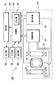
図1のブロック図及び図2の本体ケース断面図に示すように、容量式電磁流量計100は、被検出流体を通過させる測定管10と、ポールピース178の周囲に巻回され、測定管10の外部から被検出流体に磁場を印加する励磁コイル22と、励磁コイル22で交番磁界を発生させるための励磁回路24と、励磁コイル22で発生される磁界中を被検出流体が通過して発生される起電力を検出するための電極30と、電極30を介して起電力を検出する検出回路34と、励磁回路24及び検出回路34を駆動制御し、さらに検出された信号から流量を演算するための制御部40と、制御部40で演算された流量を表示する表示部51とを備える。この制御部40は、流量検出手段を構成する本体ケース110で検出された被検出流体の流量に基づき、積算流量を演算可能な流量演算部として機能する。また必要に応じて、出力信号を出力するための出力部60や、外部からのリセット信号等の各種入力信号を入力するための入力部70、各種設定を行うための設定部80等を設けてもよい。これら制御部40、表示部51、出力部60、入力部70、設定部80等は、表示ユニット50として、本体ケース110と別部材のユニット状に構成される。   As shown in the block diagram of FIG. 1 and the cross-sectional view of the main body case of FIG. 2, the capacitive electromagnetic flow meter 100 is wound around the measurement tube 10 and the pole piece 178 that allow the fluid to be detected to pass through. An excitation coil 22 for applying a magnetic field to the fluid to be detected from outside, an excitation circuit 24 for generating an alternating magnetic field by the excitation coil 22, and a fluid to be detected passing through the magnetic field generated by the excitation coil 22 The electrode 30 for detecting the electromotive force generated, the detection circuit 34 for detecting the electromotive force via the electrode 30, the excitation circuit 24 and the detection circuit 34 are driven and controlled, and the flow rate is calculated from the detected signal. And a display unit 51 that displays the flow rate calculated by the control unit 40. The control unit 40 functions as a flow rate calculation unit capable of calculating the integrated flow rate based on the flow rate of the fluid to be detected detected by the main body case 110 constituting the flow rate detection means. If necessary, an output unit 60 for outputting an output signal, an input unit 70 for inputting various input signals such as an external reset signal, a setting unit 80 for performing various settings, and the like are provided. Also good. The control unit 40, the display unit 51, the output unit 60, the input unit 70, the setting unit 80, and the like are configured as a unit that is a separate member from the main body case 110 as the display unit 50.

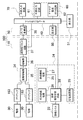
この容量式電磁流量計100の回路構成のさらに詳細なブロック図を図3に示す。この図では、容量式電磁流量計100を構成する本体ケース110と表示ユニット50各々について、これらを構成する部材を示している。まず本体ケース110側には、電極30とプリアンプ163を一対、測定管に配置している。そしてこれらの電極30で起電力を検出する検出回路34として、差動増幅器35と、増幅器36と、周期性リセット回路37を備える。図3の例では、プリアンプ163の出力は差動増幅器35に入力され、電極30間に発生した起電力を検出する。差動増幅器35の出力はさらに増幅器36で増幅されて、周期性リセット回路37を介して、A/D変換器38でA/D変換され、制御部40に入力される。周期性リセット回路37は、制御部40から周期的に送られるリセット信号を受けて、検出された電圧をリセットするための回路である。   A more detailed block diagram of the circuit configuration of the capacitive electromagnetic flow meter 100 is shown in FIG. In this figure, each of the main body case 110 and the display unit 50 constituting the capacitive electromagnetic flow meter 100 shows the members constituting them. First, a pair of electrodes 30 and preamplifiers 163 are arranged on the measurement tube on the main body case 110 side. A differential amplifier 35, an amplifier 36, and a periodic reset circuit 37 are provided as a detection circuit 34 that detects an electromotive force at these electrodes 30. In the example of FIG. 3, the output of the preamplifier 163 is input to the differential amplifier 35 to detect the electromotive force generated between the electrodes 30. The output of the differential amplifier 35 is further amplified by the amplifier 36, A / D converted by the A / D converter 38 via the periodic reset circuit 37, and input to the control unit 40. The periodic reset circuit 37 is a circuit for receiving a reset signal periodically transmitted from the control unit 40 and resetting the detected voltage.

一方、測定管に励磁コイル22で磁界を生じさせる励磁回路24としては、励磁用の励磁電源25、励磁コイル22と励磁電源25との間に介在され、励磁の極性を切り替える励磁極性切替回路28、及び励磁コイル22に所定の定電流を通電させるための定電流回路29を備える。この励磁回路24では、励磁極性切替回路28が励磁電源25より供給される電力をスイッチングして交流電流を励磁コイル22に供給し、交番磁界を発生させる。図3の例では、励磁電源25として、初期励磁電源26及び励磁継続電源27の2つを備えており、これらを切り替えて使用する。すなわち、励磁コイル22の立ち上げ時には高電圧が必要であるため、より高出力を得られる初期励磁電源26を使用する。そして励磁が安定すると、励磁を継続させるために必要な電圧は低くなるので、励磁継続電源27に切り替える。これにより、起動時の高電圧と安定動作時の定電圧とを供給するために、専用の電源を用意することで、電源が大型化したり電力損失が増すことを回避でき、装置の小型化や発熱防止が図られる。   On the other hand, as an excitation circuit 24 for generating a magnetic field in the measurement tube by the excitation coil 22, an excitation power source 25 for excitation, an excitation polarity switching circuit 28 that is interposed between the excitation coil 22 and the excitation power source 25 and switches the polarity of excitation. And a constant current circuit 29 for supplying a predetermined constant current to the exciting coil 22. In the excitation circuit 24, the excitation polarity switching circuit 28 switches the power supplied from the excitation power supply 25 and supplies an alternating current to the excitation coil 22 to generate an alternating magnetic field. In the example of FIG. 3, the excitation power supply 25 includes an initial excitation power supply 26 and an excitation continuation power supply 27, which are used by switching. That is, since a high voltage is required when the exciting coil 22 is started up, the initial exciting power source 26 that can obtain a higher output is used. When the excitation is stabilized, the voltage necessary for continuing the excitation becomes low, and the excitation continuous power supply 27 is switched. As a result, in order to supply a high voltage at start-up and a constant voltage at stable operation, a dedicated power supply can be prepared, so that an increase in power supply or an increase in power loss can be avoided. Prevents heat generation.

さらに、励磁極性切替回路28の出力は、表示ユニット50側の制御部40に入力される。表示ユニット50は、A/D変換器38と、制御部40と、表示部51と、設定部80と、入力部70と、出力部60を備える。制御部40は、マイクロコンピュータ等で構成され、これら励磁回路24と検出回路34を同期させて駆動、制御する。また設定部80は、各種の設定や操作を行うためのスイッチやコンソールである。表示部51は、7セグメント式表示器等を備え、検出された瞬時流量や積算流量、あるいは設定値などを切り替えて、又は同時に表示する。入力部70は、外部信号を入力する入力回路である。出力部60は、制御信号等を出力するための外部出力回路61とアナログ電流出力回路62を備える。   Further, the output of the excitation polarity switching circuit 28 is input to the control unit 40 on the display unit 50 side. The display unit 50 includes an A / D converter 38, a control unit 40, a display unit 51, a setting unit 80, an input unit 70, and an output unit 60. The control unit 40 is constituted by a microcomputer or the like, and drives and controls the excitation circuit 24 and the detection circuit 34 in synchronization. The setting unit 80 is a switch or console for performing various settings and operations. The display unit 51 includes a 7-segment display and the like, and switches or simultaneously displays the detected instantaneous flow rate, integrated flow rate, or set value. The input unit 70 is an input circuit that inputs an external signal. The output unit 60 includes an external output circuit 61 and an analog current output circuit 62 for outputting a control signal and the like.

なお、これら表示ユニットや本体ケース、あるいは励磁回路や検出回路などの区分けは一例であり、各構成部材が属するユニットや回路を適宜変更しても同様の機能が実現できることはいうまでもない。また、機能が実現される限りにおいて任意の部材を統合することも可能である。   It should be noted that the classification of the display unit, the main body case, the excitation circuit, the detection circuit, and the like is an example, and it goes without saying that the same function can be realized by appropriately changing the unit or circuit to which each constituent member belongs. Moreover, as long as a function is implement | achieved, it is also possible to integrate arbitrary members.

この容量式電磁流量計100の動作原理を、図1に基づいて説明する。被検出流体を導く測定管10は、測定管10の左右に配置された一対の励磁コイル22により発生し、ポールピース178に導かれたほぼ平行な磁界と直交するよう配置されている。また、測定管10の上下面に対向して配置された一対の電極30は、励磁コイル22で発生される磁界及び被検出流体の通過方向と直交する方向に発生する起電力を検出するよう配置されている。この構成において、測定管10内に被検出流体が流れる、すなわち磁界と直交する方向に導電性流体が移動すると、ファラデーの電磁誘導の法則に従い被検出流体中には、その移動速度(流速)に比例した起電力が発生する。このとき起電力はファラデーの法則により磁束密度、流速及び測定管径の積に比例する。電極30は、誘導体からなる測定管10の管壁を介して被検出流体と対向し、静電容量結合されており、流体内部に発生した起電力を電気的に取り出す働きをする。取り出された起電力は、制御部40に伝達され、流量信号に変換されて表示部51に表示され、あるいは電気信号として出力される。
(本体ケース110)
The operation principle of the capacitive electromagnetic flow meter 100 will be described with reference to FIG. The measurement tube 10 that guides the fluid to be detected is generated by a pair of exciting coils 22 disposed on the left and right sides of the measurement tube 10 and is disposed so as to be orthogonal to the substantially parallel magnetic field guided to the pole piece 178. The pair of electrodes 30 arranged to face the upper and lower surfaces of the measuring tube 10 are arranged so as to detect the electromotive force generated in the direction perpendicular to the magnetic field generated by the exciting coil 22 and the direction of passage of the fluid to be detected. Has been. In this configuration, when the fluid to be detected flows in the measuring tube 10, that is, when the conductive fluid moves in a direction orthogonal to the magnetic field, the moving speed (flow velocity) of the fluid to be detected is increased according to Faraday's law of electromagnetic induction. Proportional electromotive force is generated. At this time, the electromotive force is proportional to the product of the magnetic flux density, the flow velocity, and the measurement tube diameter according to Faraday's law. The electrode 30 faces the fluid to be detected through the tube wall of the measuring tube 10 made of a derivative and is capacitively coupled, and functions to electrically extract an electromotive force generated in the fluid. The extracted electromotive force is transmitted to the control unit 40, converted into a flow rate signal and displayed on the display unit 51, or output as an electrical signal.
(Main body case 110)

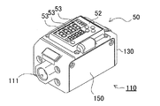
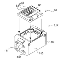
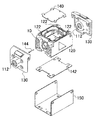
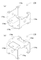
次に、各部材の詳細を図面に基づき説明する。図4及び図5に示す容量式電磁流量計100は、容量式電磁流量計本体を構成する本体ケース110と、表示ユニット50とで構成される。この容量式電磁流量計は、本体ケース110の両端面に開口された流路口111から被検出流体を内部に通過させ、その流量を検出して表示ユニット50に表示する。   Next, the detail of each member is demonstrated based on drawing. A capacitive electromagnetic flow meter 100 shown in FIGS. 4 and 5 includes a main body case 110 constituting a capacitive electromagnetic flow meter main body and a display unit 50. This capacitive electromagnetic flow meter allows the fluid to be detected to pass through the flow passage openings 111 opened at both end faces of the main body case 110, detects the flow rate, and displays it on the display unit 50.

本体ケース110には、PPS樹脂等が利用できる。特に本体ケース110を金属でなく樹脂で形成することにより、軽量化を図ると共に複雑な形状にも容易に形成でき、安価に構成できる利点が得られる。本体ケース110の上面には、図5に示すように、表示ユニット50が固定される。また本体ケース110の側面には、図6に示すように測定管10を収納するハウジング120の前後に各々サイドカバー130を固定している。各サイドカバー130には被検出流体を流入、排出するための流路口111を開口している。   PPS resin or the like can be used for the main body case 110. In particular, by forming the main body case 110 from a resin instead of a metal, it is possible to obtain an advantage that the weight can be reduced and a complicated shape can be easily formed and the structure can be made at low cost. As shown in FIG. 5, the display unit 50 is fixed to the upper surface of the main body case 110. Further, as shown in FIG. 6, side covers 130 are fixed to the side surfaces of the main body case 110 before and after the housing 120 that houses the measurement tube 10. Each side cover 130 is provided with a channel port 111 through which the fluid to be detected flows in and out.

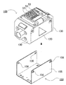
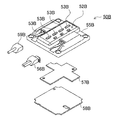
さらにサイドカバー130の上面はヨーク蓋140で、下面は補強板142で各々閉塞している。さらに補強板142を覆うように、断面コ字状の本体カバー150で被覆し、本体カバー150の両端でサイドカバー130を固定して補強している。本体ケース110を本体カバー150で被覆して、サイドカバー130同士を本体カバー150で固定する状態を図7に示す。この図に示すように、ハウジング120の前後にサイドカバー130を固定した状態で、本体カバー150の側板155を挿入できる段差を形成している。さらに本体カバー150で本体ケース110を被覆した状態で、側板155に開口された螺子孔156に螺子を挿入して、本体カバー150の両端でサイドカバー130を螺号して固定する。さらに螺子孔156は、ハウジング120とサイドカバー130との連結に兼用することもでき、これにより組み立て作業効率も向上される。   Further, the upper surface of the side cover 130 is closed with a yoke lid 140 and the lower surface is closed with a reinforcing plate 142. Furthermore, the reinforcing plate 142 is covered with a body cover 150 having a U-shaped cross section, and the side cover 130 is fixed and reinforced at both ends of the body cover 150. A state in which the main body case 110 is covered with the main body cover 150 and the side covers 130 are fixed to each other with the main body cover 150 is shown in FIG. As shown in this figure, a step is formed so that the side plate 155 of the main body cover 150 can be inserted in a state where the side cover 130 is fixed before and after the housing 120. Further, with the main body cover 150 covering the main body case 110, screws are inserted into screw holes 156 opened in the side plate 155, and the side covers 130 are screwed and fixed at both ends of the main body cover 150. Furthermore, the screw hole 156 can also be used for the connection between the housing 120 and the side cover 130, thereby improving the assembly work efficiency.

本体カバー150は、板金等剛性のある部材で構成し、両端でサイドカバー130と螺子で螺号する等して、容量式電磁流量計の筐体に強度を持たせる。これにより、容量式電磁流量計を配管する際に、容量式電磁流量計の両側に設けられた配管固定機構に応力が加えられても、十分対抗できる強度を付与できる。例えば流路口111の内面に設けられた螺子溝112を螺号すると、両端から逆向きのトルクが加えられるが、このような捻れ応力で本体ケース110が破損しないよう本体カバー150が補強する。   The main body cover 150 is made of a rigid member such as a sheet metal, and gives strength to the casing of the capacitive electromagnetic flow meter by screwing the side cover 130 with screws at both ends. Thereby, when piping a capacity type electromagnetic flow meter, even if stress is applied to the piping fixing mechanism provided on both sides of the capacity type electromagnetic flow meter, it is possible to give strength that can sufficiently resist. For example, when the screw groove 112 provided on the inner surface of the flow path port 111 is screwed, torque in the opposite direction is applied from both ends, but the main body cover 150 reinforces the main body case 110 from being damaged by such twisting stress.

また、容量式電磁流量計の筐体全体を金属製とするのでなく、本体ケース110を樹脂部材とすることで軽量化も図られる。本体カバー150は金属製ではあるが比較的軽量な板金で構成することにより、全体としての軽量化が実現できる。さらに本体ケース110を複雑な形状としても、金属製の場合と比較して安価に形成でき、コスト面でも有利となる。特に金属部品は単純な板金形状とすることで、安価とできる。さらにまた、容量式電磁流量計の本体ケース110表面を板金等の本体カバー150で被覆することにより、筐体表面を保護する効果も得られる。加えて、両端のサイドカバー130同士を金属製の本体カバー150で連結することにより、両端面を導通させてアース電位を共通にできるという副次的な効果も得られる。一方、本体ケース110には液アース端子144を備えており、被検出流体の電位をサイドカバー130の接地電位とする。   In addition, the entire casing of the capacitive electromagnetic flow meter is not made of metal, but the weight can be reduced by using the main body case 110 as a resin member. Although the main body cover 150 is made of a metal but relatively light metal plate, the overall weight can be reduced. Furthermore, even if the main body case 110 has a complicated shape, it can be formed at a lower cost than the case of metal, which is advantageous in terms of cost. In particular, metal parts can be made inexpensive by using a simple sheet metal shape. Furthermore, by covering the surface of the main body case 110 of the capacitive electromagnetic flow meter with a main body cover 150 such as a sheet metal, an effect of protecting the housing surface can be obtained. In addition, by connecting the side covers 130 at both ends with the metal main body cover 150, a secondary effect that the both end surfaces are made conductive and the ground potential can be made common can be obtained. On the other hand, the main body case 110 is provided with a liquid earth terminal 144, and the potential of the fluid to be detected is set to the ground potential of the side cover 130.

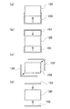
本体カバー150は、上記の例では図8(a)に示すように一枚の断面コ字状本体カバー150でハウジング120全体をカバーする構成とした。特に板金を断面コ字状に折曲することで、曲げ強度を一層増すことができる。また本体カバー150一枚でサイドカバー130同士を連結できるので、部品点数も最小限とでき、組み立て作業性にも優れる。ただ、本体カバーは、上記の構成に限られず、複数枚で構成してもよい。例えば図8(b)に示すように、本体カバー151を2枚、それぞれ断面コ字状とし、これらをハウジング120の上下から覆うように構成することもできる。あるいは図8(c)に示すように、断面L字状の本体カバー152とし、これらをハウジング120の対角線方向から狭持する構成としてもよい。さらに図8(d)に示すように、2枚の平板状本体カバー153を使用して、サイドカバー同士を橋渡しする構成としても良い。
(サイドカバー130)
In the above example, the main body cover 150 is configured to cover the entire housing 120 with a single U-shaped main body cover 150 as shown in FIG. In particular, the bending strength can be further increased by bending the sheet metal into a U-shaped cross section. Further, since the side covers 130 can be connected to each other with a single body cover 150, the number of parts can be minimized and the assembly workability is excellent. However, the main body cover is not limited to the above configuration, and may be configured by a plurality of sheets. For example, as shown in FIG. 8B, two main body covers 151 each having a U-shaped cross section may be formed so as to cover them from above and below the housing 120. Alternatively, as shown in FIG. 8C, a main body cover 152 having an L-shaped cross section may be used, and these may be sandwiched from the diagonal direction of the housing 120. Further, as shown in FIG. 8D, a configuration may be used in which the side covers are bridged by using two flat plate-like body covers 153.
(Side cover 130)

サイドカバー130は、流路口111を開口している。流路口111は、本体ケース110に内蔵される測定管10とで流路を構成する。流路の口径は、流路口111の一端から他端までほぼ同じ直径として、この流路に被検出流体を一方向に流す際の損失を低減する。流路口111の部分には、容量式電磁流量計を設置する工場等の外部配管(図示せず)と接続するための配管固定機構として、流路口111の内面に螺子溝112が形成されている。螺合により配管する際の機械的強度を確保するために、好ましくはサイドカバー130を金属で一体に形成する。なお外部配管と流路との他の接続方法としては、本体ケースの開口端面にボルトを植設し、他方、外部配管の端にフランジを設け、このフランジの挿通孔にボルトを通した後にナットを螺着させることによって本体ケースと外部配管とを接続するようにしてもよい。
(測定管10)
The side cover 130 opens the flow path port 111. The channel port 111 constitutes a channel with the measurement tube 10 built in the main body case 110. The diameter of the flow path is set to substantially the same diameter from one end to the other end of the flow path port 111 to reduce loss when the detected fluid flows in one direction in the flow path. A thread groove 112 is formed on the inner surface of the channel port 111 at the channel port 111 as a piping fixing mechanism for connecting to an external piping (not shown) of a factory or the like where a capacitive electromagnetic flow meter is installed. . In order to ensure mechanical strength when piping by screwing, the side cover 130 is preferably formed integrally with metal. As another connection method between the external pipe and the flow path, a bolt is planted on the open end face of the main body case, and on the other hand, a flange is provided at the end of the external pipe, and the nut is passed through the bolt through the flange insertion hole. The main body case and the external pipe may be connected by screwing.
(Measurement tube 10)

測定管10は、管状の内部に被検出流体を通過させる絶縁性ライニングである。測定管10には、被検出流体を通過させるパイプとしての優れた耐薬品性能と、コンデンサを構成するための電気的特性とが要求される。機械的特性の面からは、測定管10は、被検出流体の圧力、温度変化による配管の伸縮に基づく引張又は圧縮の力を担う強度母体とし、かつそれに耐える所要の内径、肉厚、長さを有する剛構造部材とする。一方、電気的特性の面からは、測定管10は非磁性の絶縁性部材として誘電体材料であることが望まれる。特に測定管10の周囲に貼付される電極30と被検出流体との静電容量結合を高めS/N比を改善するために、誘電率の高い材質で構成する。このような材質としてはセラミックスやプラスチックが利用できる。一般的にはセラミックスが用いられるが、測定管の外周面に、後述する位置決めのための突起12や段差14を一体的に形成する場合、成形時の熱収縮による位置決め精度の低下や、後加工でこのような突起や段差を形成するとコスト的に高くなるおそれがある。このため、本実施の形態では比較的強度があり、且つ成形精度と高誘電性を確保できるセラミックスを混入したPPS樹脂を採用している。PPS樹脂は、耐油、耐薬品性等に優れる。本実施の形態では、ポリプラスチックス株式会社製フレクティス(登録商標)を使用した。また測定管10の内面には必要に応じてライニングが施工される。   The measurement tube 10 is an insulating lining that allows a fluid to be detected to pass through the inside of the tube. The measuring tube 10 is required to have excellent chemical resistance as a pipe through which a fluid to be detected passes and electrical characteristics for constituting a capacitor. From the viewpoint of mechanical characteristics, the measuring tube 10 is a strength matrix that bears the force of tension or compression based on the expansion and contraction of the pipe due to pressure and temperature change of the fluid to be detected, and the required inner diameter, thickness, and length to withstand it. A rigid structural member having On the other hand, from the viewpoint of electrical characteristics, the measuring tube 10 is desirably a dielectric material as a nonmagnetic insulating member. In particular, the electrode 30 is made of a material having a high dielectric constant in order to enhance the capacitive coupling between the electrode 30 attached around the measuring tube 10 and the fluid to be detected and to improve the S / N ratio. Ceramics and plastics can be used as such materials. In general, ceramics are used. However, when a protrusion 12 and a step 14 for positioning, which will be described later, are integrally formed on the outer peripheral surface of the measuring tube, the positioning accuracy is reduced due to thermal shrinkage during molding, or post-processing is performed. If such protrusions and steps are formed, the cost may increase. For this reason, in the present embodiment, a PPS resin mixed with ceramics that has relatively high strength and can ensure molding accuracy and high dielectric property is employed. PPS resin is excellent in oil resistance and chemical resistance. In the present embodiment, Flexis (registered trademark) manufactured by Polyplastics Co., Ltd. was used. A lining is applied to the inner surface of the measuring tube 10 as necessary.

被検出流体は、水や非腐食性の液体であり、所定の導電率を備える液体である。容量式電磁流量計は、接液式の電磁流量計と異なり、電極30を被検出流体に直接接触させないため、従来は使用できなかった電極を腐食するような液体であっても測定できる。また、測定管10の材質を選択することによって、様々な被検出流体に対応できる。特に、測定精度等に対応して要求される誘電率と、被検出流体に対する耐性に応じて、測定管10の材質を選択できる。特に本実施の形態に係る容量式電磁流量計は、測定管10を本体ケース110と別部材としているので、測定管10のみを変更し、他の構成部品を共通化して様々な仕様の容量式電磁流量計を構成でき、製品仕込みの上で有利なものとなる。   The fluid to be detected is water or a non-corrosive liquid, and is a liquid having a predetermined conductivity. Unlike the liquid contact type electromagnetic flow meter, the capacity type electromagnetic flow meter does not directly contact the electrode 30 with the fluid to be detected. Therefore, even a liquid that corrodes an electrode that could not be used conventionally can be measured. Moreover, it can respond to various to-be-detected fluids by selecting the material of the measuring tube 10. FIG. In particular, the material of the measuring tube 10 can be selected according to the dielectric constant required in accordance with the measurement accuracy and the resistance to the fluid to be detected. In particular, since the capacitive electromagnetic flow meter according to the present embodiment uses the measurement tube 10 as a separate member from the main body case 110, only the measurement tube 10 is changed, and other component parts are used in common, so that the capacitance type has various specifications. An electromagnetic flow meter can be configured, which is advantageous for product preparation.

さらに測定管10には、円柱状の測定管10の回転を阻止するための回転阻止機構を設けている。すなわち、測定管10の周囲で電極30と励磁コイル22とを直交させる必要があるため、円柱状の測定管10が回転して位置ずれを生じると、正確な検出に支障を来すおそれがある。このため、図9(a)に示すように測定管10の外周に突起12を設けている。突起12を支承する孔をプリアンプモジュール160や本体ケース110等に形成することで、測定管10を所定の姿勢に位置決めし、回転を阻止する。   Further, the measurement tube 10 is provided with a rotation blocking mechanism for blocking the rotation of the columnar measurement tube 10. That is, since it is necessary to make the electrode 30 and the exciting coil 22 orthogonal to each other around the measurement tube 10, if the cylindrical measurement tube 10 is rotated and misaligned, accurate detection may be hindered. . For this reason, as shown in FIG. 9A, a projection 12 is provided on the outer periphery of the measuring tube 10. By forming a hole for supporting the protrusion 12 in the preamplifier module 160, the main body case 110, and the like, the measuring tube 10 is positioned in a predetermined posture and rotation is prevented.

測定管10は、本体ケース110と別部材とする。これにより、測定管10を構成する部材にはコンデンサに適した材質を選択できる。一方で本体ケース110は、複雑な形状にも容易に成型可能な樹脂が使用できる。このように、測定管10を本体ケース110と別部材とすることにより、各々に適した部材で構成できる。特に測定管を構成する高誘電材料は一般に高価であるため、必要な部分のみを高価な部材で構成し、他の部材はより安価な材質として全体のコストを低減できる。また、容量式電磁流量計に要求される精度等に応じて、適切な材質の測定管10を選定できる。さらに、口径の異なる測定管に交換することもできる。このように、容量式電磁流量計の検出目的や用途、求められる仕様やコストに応じて、適切な材質の測定管を選定することができる。また、複数の測定管を一の容量式電磁流量計にセット可能とすることで、多品種の容量式電磁流量計の部材を共通化して、安価に提供できる。
(電極30)
The measurement tube 10 is a separate member from the main body case 110. Thereby, the material suitable for a capacitor | condenser can be selected for the member which comprises the measurement pipe | tube 10. FIG. On the other hand, a resin that can be easily molded into a complicated shape can be used for the main body case 110. Thus, by making the measuring tube 10 a separate member from the main body case 110, it can be configured by a member suitable for each. In particular, since the high dielectric material constituting the measuring tube is generally expensive, only necessary portions are made of expensive members, and the other members can be made of less expensive materials to reduce the overall cost. Moreover, the measuring tube 10 made of an appropriate material can be selected according to the accuracy required for the capacity type electromagnetic flow meter. Furthermore, it can be replaced with a measuring tube having a different diameter. Thus, a measuring tube made of an appropriate material can be selected according to the detection purpose and application of the capacity type electromagnetic flow meter, the required specifications and cost. In addition, by making it possible to set a plurality of measurement tubes in one capacity type electromagnetic flow meter, the members of various types of capacity type electromagnetic flow meters can be shared and provided at low cost.
(Electrode 30)

測定管10の周囲には電極30が配置される。電極30は、ポリイミド等の絶縁テープに銅箔をコーティングしたものが使用できる。この電極30は、図9(b)に示すように、円筒状の測定管10の外周に沿うように湾曲された面状の導電体であり、一対の電極30を測定管10を挟んで対向するように配置する。このように一対の電極30と被検出流体との静電結合により、流体中に発生した起電力を測定管10から外部に取り出して、流量を検出できる。各電極30は、測定管10の外周に隙間なく貼付される。貼付にはテープや接着剤等が利用できる。電極30は、好ましくは可撓性部材で構成することにより、測定管10の外面に隙間なく固定できる。   An electrode 30 is disposed around the measurement tube 10. As the electrode 30, an insulating tape such as polyimide coated with a copper foil can be used. As shown in FIG. 9B, the electrode 30 is a planar conductor that is curved along the outer periphery of the cylindrical measurement tube 10, and the pair of electrodes 30 are opposed to each other with the measurement tube 10 interposed therebetween. Arrange to do. Thus, by electrostatic coupling between the pair of electrodes 30 and the fluid to be detected, the electromotive force generated in the fluid can be taken out from the measuring tube 10 and the flow rate can be detected. Each electrode 30 is affixed to the outer periphery of the measuring tube 10 without a gap. Tape or adhesive can be used for pasting. The electrode 30 is preferably made of a flexible member and can be fixed to the outer surface of the measuring tube 10 without a gap.

また面状の導電体である電極の腐食や結露による一対の電極間の導通を防止するために、導電体は絶縁層で被覆することが好ましい。図9の例では、シリコーン樹脂等の絶縁性の接着材を介して測定管10の外周に接着することにより、絶縁層の形成と接着を同時に実現している。また、その他の構成として絶縁層としてポリイミド樹脂テープを使用し、ポリイミド樹脂テープ上に銅箔の面状導電体を予め設けた電極30を、測定管10上に配置する構成とすることもできる。測定管10の周囲には、電極30を配置する位置及び大きさに段差14を形成しており、電極30の位置決めを実現する。段差14は、測定管10外周の肉厚を薄くすることで形成している。   In order to prevent conduction between the pair of electrodes due to corrosion or condensation of the electrode which is a planar conductor, the conductor is preferably covered with an insulating layer. In the example of FIG. 9, the insulating layer is formed and bonded simultaneously by bonding to the outer periphery of the measuring tube 10 via an insulating adhesive such as silicone resin. As another configuration, a polyimide resin tape may be used as the insulating layer, and an electrode 30 in which a copper foil planar conductor is previously provided on the polyimide resin tape may be disposed on the measuring tube 10. Around the measurement tube 10, a step 14 is formed at the position and size where the electrode 30 is disposed, and the positioning of the electrode 30 is realized. The step 14 is formed by reducing the thickness of the outer circumference of the measuring tube 10.

さらに電極30は、プリアンプモジュール160と電気接続するためのリードを設ける。図9の例では、銅箔の面状導電体の一部に切り込みを入れてリード片32とし、これを引き出している。この構成は、リードの配線等を不要とし、極めて安価且つ容易に電極30の配線を行うことができる。   Further, the electrode 30 is provided with leads for electrical connection with the preamplifier module 160. In the example of FIG. 9, a lead piece 32 is formed by cutting a part of a sheet conductor of copper foil, and this is pulled out. This configuration eliminates the need for lead wiring or the like, and enables wiring of the electrode 30 to be performed very inexpensively and easily.

なおこの例では一対の電極を使用したが、2組以上の電極を使用することも可能である。複数組の電極を使用する場合、各電極で検出する電界が磁界と直交するように、電極の位置は調整される。
(ハウジング120)
Although a pair of electrodes is used in this example, two or more sets of electrodes can be used. When a plurality of sets of electrodes are used, the positions of the electrodes are adjusted so that the electric field detected by each electrode is orthogonal to the magnetic field.
(Housing 120)

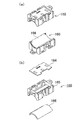
次にハウジング120の内部に収納される部材を、図10の分解斜視図に基づいて説明する。この図に示すように、ハウジング120は測定管10と、一対のプリアンプと、励磁モジュール170とを備える。またハウジング120の前後には貫通孔121が開口され、ここに測定管10が挿入される。またハウジング120内部に保持される測定管10の上下に、プリアンプが配置される。図11に示すように、電極30を装着した状態で、測定管10の上下からプリアンプモジュール160にて狭持する。
(プリアンプ)
Next, members housed in the housing 120 will be described based on the exploded perspective view of FIG. As shown in this figure, the housing 120 includes a measuring tube 10, a pair of preamplifiers, and an excitation module 170. A through-hole 121 is opened before and after the housing 120, and the measuring tube 10 is inserted therein. Preamplifiers are arranged above and below the measurement tube 10 held inside the housing 120. As shown in FIG. 11, the preamplifier module 160 holds the electrode 30 from above and below with the electrode 30 attached.
(Preamplifier)

プリアンプモジュール160は、信号増幅用のプリアンプを構成する。容量式電磁流量計においては、電極30と被検出流体との静電容量結合が一般に数十pF程度と小さいため、電気信号を通すためのフィルタを設ける際の抵抗のインピーダンスが極めて高くなっている。このため、各電極30に検出回路34としてプリアンプを接続してインピーダンスを下げる。図10に示すプリアンプは、測定管10に配置される一対の電極30と電気的に接続され、検出された電気信号を増幅して制御部40に送出する。このプリアンプは、プリアンプモジュール160を、シールドケース161に収納し、さらにシールドカバー162で閉塞し、電極30を含むプリアンプを確実にシールドして電気信号をノイズから保護する。
(プリアンプモジュール160)
The preamplifier module 160 constitutes a preamplifier for signal amplification. In the capacitive electromagnetic flow meter, since the capacitive coupling between the electrode 30 and the fluid to be detected is generally as small as several tens of pF, the impedance of the resistance when providing a filter for passing an electrical signal is extremely high. . For this reason, a preamplifier is connected to each electrode 30 as a detection circuit 34 to lower the impedance. The preamplifier shown in FIG. 10 is electrically connected to a pair of electrodes 30 arranged in the measurement tube 10, amplifies the detected electrical signal, and sends it to the control unit 40. In this preamplifier, the preamplifier module 160 is housed in a shield case 161 and is further closed by a shield cover 162, so that the preamplifier including the electrode 30 is reliably shielded to protect the electrical signal from noise.
(Preamplifier module 160)

プリアンプモジュール160の外観を図11に示す。この図において、図11(a)は一対のプリアンプモジュール160の斜視図を、図11(b)はプリアンプモジュール160の分解斜視図を、それぞれ示している。各プリアンプモジュール160は、図11(b)に示すように、プリアンプ基板164と、プリアンプ基板ホルダ165と、電極保護シート166とで構成される。プリアンプ基板164は、電極30で検出された電気信号増幅用の電子部品を実装する。プリアンプ基板164は、プリアンプ基板ホルダ165に保持される。図11(b)に示すプリアンプ基板ホルダ165は、上面にプリアンプ基板164を保持する開口を形成している。またプリアンプ基板ホルダ165は、下面を測定管10の側面に沿うようアーチ状に湾曲させており、この湾曲面に電極保護シート166を固定する。電極保護シート166は、ゴム等の弾性体で構成され、プリアンプ基板ホルダ165の湾曲面で押圧されて、電極30を測定管10の周囲に隙間なく押圧する。特に電極30による静電容量結合を高めるため、電極30と測定管10との間に隙間が生じないように固定する必要がある。この作業を、電極保護シート166を利用することで、プリアンプモジュール160を測定管10にセットする際に、電極30を測定管10の周囲に確実に押圧して隙間なく固定でき、信頼性を高めると共に構成を簡素化して作業能率も向上する。
(励磁モジュール170)
An appearance of the preamplifier module 160 is shown in FIG. 11A is a perspective view of a pair of preamplifier modules 160, and FIG. 11B is an exploded perspective view of the preamplifier module 160. Each preamplifier module 160 includes a preamplifier substrate 164, a preamplifier substrate holder 165, and an electrode protection sheet 166, as shown in FIG. The preamplifier substrate 164 is mounted with an electronic component for amplifying the electric signal detected by the electrode 30. The preamplifier substrate 164 is held by a preamplifier substrate holder 165. The preamplifier substrate holder 165 shown in FIG. 11B has an opening for holding the preamplifier substrate 164 on the upper surface. The preamplifier substrate holder 165 has a lower surface curved in an arch shape along the side surface of the measuring tube 10, and the electrode protection sheet 166 is fixed to the curved surface. The electrode protection sheet 166 is made of an elastic body such as rubber and is pressed by the curved surface of the preamplifier substrate holder 165 to press the electrode 30 around the measuring tube 10 without a gap. In particular, in order to enhance the capacitive coupling by the electrode 30, it is necessary to fix the electrode 30 and the measuring tube 10 so that no gap is generated. By using the electrode protection sheet 166 for this work, when the preamplifier module 160 is set on the measurement tube 10, the electrode 30 can be reliably pressed around the measurement tube 10 and fixed without a gap, thereby improving reliability. At the same time, the configuration is simplified to improve the work efficiency.
(Excitation module 170)

さらに、図10に示すハウジング120は、測定管10の左右側面を挟むように、励磁モジュール170が配置される。励磁モジュール170は、励磁コイル22を備えており、測定管10の左右から磁界を付与する。したがって、電極30により検出される電界と磁界が直交するように、励磁モジュール170とプリアンプの配置位置が設定される。   Furthermore, the excitation module 170 is arrange | positioned so that the housing 120 shown in FIG. The excitation module 170 includes an excitation coil 22 and applies a magnetic field from the left and right of the measurement tube 10. Therefore, the arrangement positions of the excitation module 170 and the preamplifier are set so that the electric field and magnetic field detected by the electrode 30 are orthogonal to each other.

励磁モジュール170の斜視図を図12に示す。図12(a)は励磁モジュール170を斜め上方から見た斜視図、図12(b)は斜め下方から見た斜視図を、それぞれ示している。この図に示す励磁モジュール170は、励磁コイル22を保持するコイルケース172と、コイルケース172を一対、対向するように固定する励磁プレート174と、中継基板176で構成される。
(励磁プレート174)
A perspective view of the excitation module 170 is shown in FIG. FIG. 12A shows a perspective view of the excitation module 170 as viewed obliquely from above, and FIG. 12B shows a perspective view as seen from obliquely below. The excitation module 170 shown in this figure includes a coil case 172 that holds the excitation coil 22, an excitation plate 174 that fixes the coil case 172 as a pair so as to face each other, and a relay substrate 176.
(Excitation plate 174)

励磁プレート174の斜視図を図13(a)、(b)に示す。励磁プレート174は、一対のコイルケース172を離間させて保持し、コイルケース172のポールピース178同士の間で磁界を生じさせる。この励磁プレート174は、ほぼ平行に離間させた対向片174aを、連結片174bの両端で連結した断面ほぼコ字状に形成され、対向片174aに各々コイルケース172を保持して、これらを平行に離間させて保持する。また励磁プレート174の上面の両端部には、ヨーク蓋固定用のヨーク片174cが各々形成される。   A perspective view of the excitation plate 174 is shown in FIGS. The excitation plate 174 holds the pair of coil cases 172 apart from each other, and generates a magnetic field between the pole pieces 178 of the coil case 172. The excitation plate 174 is formed in a substantially U-shaped cross-section in which opposed pieces 174a that are separated from each other in parallel are connected at both ends of the connecting piece 174b. Each of the exciting pieces 174a holds a coil case 172, and these are parallel. And keep them apart. Further, yoke pieces 174c for fixing the yoke lid are formed at both ends of the upper surface of the excitation plate 174, respectively.

励磁プレート174は、励磁コイル22で発生される磁界で磁気回路を構成するため、強磁性体材料で構成する。この励磁プレート174は、金属等で一体に形成している。また対向するポールピース178同士の間で磁界が効率よく発生されるように、いいかえるとポールピース178から発される磁束が、下方向の連結片174bに向かう漏れ磁束を低減するため、励磁プレート174の一部を部分的に開口している。特に、連結片174bと対向片174aとの接合部分を大きく開口して開口部174dを形成することにより、磁気回路の短絡を防止する。このような形状の励磁プレート174を使用することで、漏れ磁場を低減し、磁気回路の効率を高めることができる。
(中継基板176)
The excitation plate 174 is made of a ferromagnetic material because it forms a magnetic circuit with the magnetic field generated by the excitation coil 22. The excitation plate 174 is integrally formed of metal or the like. In other words, the magnetic flux generated from the pole piece 178 reduces the leakage magnetic flux toward the downward connecting piece 174b so that a magnetic field is efficiently generated between the opposing pole pieces 178. Is partially open. In particular, a magnetic circuit is prevented from being short-circuited by forming an opening 174d by greatly opening a joint portion between the connecting piece 174b and the opposing piece 174a. By using the excitation plate 174 having such a shape, the leakage magnetic field can be reduced and the efficiency of the magnetic circuit can be increased.
(Relay board 176)

また図12(b)に示すように、励磁プレート174の連結片174bの裏面には、中継基板176が固定される。中継基板176は、励磁コイル22を励磁する励磁回路24として、図3に示す初期励磁電源26、励磁継続電源27、励磁極性切替回路28、定電流回路29を構成する。励磁回路24でポールピース178同士の間で交番磁場を発生させるように、中継基板176には必要な電気回路が実装される。この励磁モジュール170は、商用周波数と異なる周波数で交番磁場を発生させる。好ましくは、励磁周波数は商用周波数よりも高い周波数、例えば75kHzとする。これにより、商用周波数で生じるノイズを回避することができる。
(コイルケース172)
As shown in FIG. 12B, a relay substrate 176 is fixed to the back surface of the connecting piece 174b of the excitation plate 174. The relay substrate 176 constitutes an initial excitation power supply 26, an excitation continuation power supply 27, an excitation polarity switching circuit 28, and a constant current circuit 29 shown in FIG. 3 as the excitation circuit 24 for exciting the excitation coil 22. A necessary electric circuit is mounted on the relay substrate 176 so that the excitation circuit 24 generates an alternating magnetic field between the pole pieces 178. The excitation module 170 generates an alternating magnetic field at a frequency different from the commercial frequency. Preferably, the excitation frequency is higher than the commercial frequency, for example, 75 kHz. Thereby, the noise which arises in a commercial frequency can be avoided.
(Coil case 172)

コイルケース172は、コアを挿入し、コアの周囲に励磁コイル22を捲回する構成とする。コイルケース172の分解斜視図を図14に示す。この図に示すように、コイルケース172は中空の軸で平板172a、172bを連結した形状とし、平板172a、172b同士の間に励磁コイル22を捲回するコイル捲回空間172cが形成される。一方の平板172aには、コアとしてポールピース178を挿入するポールピース挿入口172dが開口される。またポールピース挿入口172dは中空の軸状とし、コイル捲回空間172cを貫通している。さらに他方の平板172bは矩形状とし、図12(a)に示すように励磁プレート174の対向片174aに固定される。
(ポールピース178)
The coil case 172 has a configuration in which a core is inserted and the exciting coil 22 is wound around the core. An exploded perspective view of the coil case 172 is shown in FIG. As shown in this figure, the coil case 172 has a shape in which flat plates 172a and 172b are connected by a hollow shaft, and a coil winding space 172c for winding the exciting coil 22 is formed between the flat plates 172a and 172b. One flat plate 172a has a pole piece insertion opening 172d into which a pole piece 178 is inserted as a core. The pole piece insertion port 172d has a hollow shaft shape and penetrates the coil winding space 172c. Further, the other flat plate 172b has a rectangular shape and is fixed to the opposing piece 174a of the excitation plate 174 as shown in FIG.
(Pole piece 178)

励磁コイル22はポールピースコア178aの周囲に捲回される。ポールピース178は、ポールピースコア178aをなす鉄芯の一端に矩形状の平板178bを固定し、平板178bを介して磁束が出入りする。ポールピースコア178aには積層鉄心等の導電性の磁性材が好適に使用できる。またポールピースコアを使用しないで、この部分で生じる磁気回路遅れを低減する構成としてもよい。   The exciting coil 22 is wound around the pole piece core 178a. The pole piece 178 has a rectangular flat plate 178b fixed to one end of an iron core forming the pole piece core 178a, and magnetic flux enters and exits through the flat plate 178b. A conductive magnetic material such as a laminated iron core can be suitably used for the pole piece core 178a. Moreover, it is good also as a structure which reduces the magnetic circuit delay which arises in this part, without using a pole piece core.

この励磁モジュール170は、内蔵される一対の励磁コイル22を離間して配置し、中継基板176で励磁コイル22を励磁してポールピース178同士の間に磁界を生じさせる。これにより、ポールピース178の間に設置された測定管10に対して、被検出流体として導電率を有する液体を流すと、液体の運動方向と直交する方向に起電力を生じさせる。   In this excitation module 170, a pair of built-in excitation coils 22 are arranged apart from each other, and the excitation coil 22 is excited by the relay substrate 176 to generate a magnetic field between the pole pieces 178. As a result, when a liquid having conductivity as the fluid to be detected flows through the measuring tube 10 installed between the pole pieces 178, an electromotive force is generated in a direction orthogonal to the moving direction of the liquid.

なお図1の例では、励磁コイル22を2つ使用し、測定管10の左右に設けているが、コイルを一とすることもできる。例えば図20に示すようにコア178Bの両端で測定管10Bを挟むようにすれば、コア178Bに捲回する励磁コイル22Bを一とできる。この図に示す容量式電磁流量計も、図1等と同様に、励磁回路24Bで励磁コイル22Bを励磁し、測定管10Bを通過する被検出流体により生じる起電力を検出回路34Bが電極30Bで検出し、制御部40Bに送出して表示部51Bにて表示する。   In the example of FIG. 1, two exciting coils 22 are used and are provided on the left and right of the measuring tube 10, but the number of coils may be one. For example, as shown in FIG. 20, if the measurement tube 10B is sandwiched between both ends of the core 178B, the exciting coil 22B wound around the core 178B can be integrated. Similarly to FIG. 1 and the like, the capacitive electromagnetic flow meter shown in this figure excites the exciting coil 22B with the exciting circuit 24B, and the detection circuit 34B detects the electromotive force generated by the fluid to be detected passing through the measuring tube 10B with the electrode 30B. It is detected, sent to the control unit 40B, and displayed on the display unit 51B.

さらに図5に戻り、容量式電磁流量計は、本体ケース110の上面に、表示ユニット50を固定している。本体ケース110の上面には、表示ユニット50を固定するための螺子孔122をハウジング120の四隅に形成している。また、サイドカバー130の上端は、本体ケース110上面に固定された表示ユニット50の表面と同一平面となるよう、窪ませた段差空間が形成されている。この段差空間は、表示ユニット50の外形及び大きさとほぼ等しいか、これよりも若干大きく形成される。
(表示ユニット50)
Further, returning to FIG. 5, the capacitive electromagnetic flow meter has the display unit 50 fixed to the upper surface of the main body case 110. Screw holes 122 for fixing the display unit 50 are formed at the four corners of the housing 120 on the upper surface of the main body case 110. In addition, a recessed step space is formed at the upper end of the side cover 130 so as to be flush with the surface of the display unit 50 fixed to the upper surface of the main body case 110. This step space is formed to be approximately equal to or slightly larger than the outer shape and size of the display unit 50.
(Display unit 50)

表示ユニット50は被検出流体の流量等の情報を表示するための部材であり、図4等に示すように表示部51として表示画面52を備える。図4の例では表示画面52に数値を表示する数値表示領域として、7セグメント式表示器を使用しており、流量等を数値で表示する。7セグメント式表示器には、検出した流量について、瞬時流量や積算流量等の数値を表示する。この図に示す表示画面52は、7セグメント式表示器を2段備えており、積算流量と設定値とを同時に表示可能としている。ただ、7セグメント式表示器を1画面のみ設けて、積算流量や瞬時流量、設定値等の表示を切り替え可能とすることも可能であることはいうまでもない。   The display unit 50 is a member for displaying information such as the flow rate of the fluid to be detected, and includes a display screen 52 as the display unit 51 as shown in FIG. In the example of FIG. 4, a 7-segment display is used as a numerical display area for displaying numerical values on the display screen 52, and the flow rate and the like are displayed numerically. The 7-segment display displays numerical values such as instantaneous flow rate and integrated flow rate for the detected flow rate. The display screen 52 shown in this figure includes two stages of 7-segment displays, and can display the integrated flow rate and the set value simultaneously. However, it is needless to say that the display of the integrated flow rate, the instantaneous flow rate, the set value, etc. can be switched by providing only one screen with a 7-segment display.

また表示画面52は、被検出流体の流速や流れ方向を示す流体表示灯53を備える。流体表示灯53は、バー状に配置されたLEDで構成される。流体表示灯53は、例えば流量に応じた速さでLEDを流れ方向に順次点灯させ、流速と流れ方向を感覚的に表現できる。またバー状LEDに代わって、矢印形の表示灯等も利用できる。さらに、LED等を使用したセグメント式の表示画面52に代わって、液晶や有機EL等を使用した表示画面とすることも可能である。このように表示画面52には、流量等の数値のみならず矢印等の図形やイメージを併せて、あるいは択一的に表示させることができ、検出した流量等の情報をユーザに視認しやすい形で表示できる。   The display screen 52 includes a fluid display lamp 53 that indicates the flow velocity and the flow direction of the fluid to be detected. The fluid indicator lamp 53 is composed of LEDs arranged in a bar shape. The fluid indicator 53 can light up the LEDs sequentially in the flow direction at a speed corresponding to the flow rate, for example, and can express the flow velocity and the flow direction sensuously. Moreover, instead of the bar-shaped LED, an arrow-shaped indicator lamp or the like can be used. Furthermore, instead of the segment-type display screen 52 using LEDs or the like, a display screen using liquid crystal or organic EL can be used. In this way, the display screen 52 can display not only numerical values such as flow rate but also figures and images such as arrows or alternatively, and can easily display the detected flow rate information to the user. Can be displayed.

また表示ユニット50は、各種の設定を行う設定部80として操作パネル54を備えている。操作パネル54は、各種の設定を行うためのキーやボタンを備えている。図4等の例では、表示画面52に4桁の7セグメント式表示器を2段に配置し、さらに右下に操作パネル54を設け、十字方向にキーを配置している。   The display unit 50 also includes an operation panel 54 as a setting unit 80 for performing various settings. The operation panel 54 includes keys and buttons for performing various settings. In the example of FIG. 4 and the like, a 4-digit 7-segment display is arranged in two stages on the display screen 52, an operation panel 54 is provided in the lower right, and keys are arranged in the cross direction.

なお、この例では表示画面52を表示する表示回路に、検出回路34及び励磁回路24と接続されてこれらを制御する制御部40を組み込んでいる。ただ、制御回路を個別の部材で構成し、本体ケース110内に組み込むことも可能であることは言うまでもない。また制御回路や検出回路、励磁回路等を統合することも可能である。
(出力部60)
In this example, the display circuit that displays the display screen 52 incorporates a control unit 40 that is connected to the detection circuit 34 and the excitation circuit 24 and controls them. However, it goes without saying that the control circuit can be formed of individual members and incorporated in the main body case 110. It is also possible to integrate a control circuit, a detection circuit, an excitation circuit, and the like.
(Output unit 60)

また、この表示ユニット50は出力部60を備えている。この例では、出力部60は制御出力、アナログ出力、タイムアウト出力を備え、各々の出力に応じた外部出力端子を備えている。制御出力は、容量式電磁流量計で外部機器のON/OFF動作を直接制御するON/OFF出力として使用できる。この場合は、検出された瞬時流量が所定値に達したときにON/OFF出力を切り替えるように、HIGH/LOWの2つの状態に出力するスイッチとして機能する。スイッチ機能は、ノーマルオープン、ノーマルクローズのいずれとしてもよい。あるいは、制御出力として、検出された積算流量に応じたパルス電圧を出力することもできる。この場合は、外部の電圧入力機器に対して、積算流量で制御する用途等に利用できる。また、積算流量をリセットするリセット信号入力端子を備えてもよい。   Further, the display unit 50 includes an output unit 60. In this example, the output unit 60 includes a control output, an analog output, and a timeout output, and includes an external output terminal corresponding to each output. The control output can be used as an ON / OFF output for directly controlling the ON / OFF operation of an external device with a capacitive electromagnetic flow meter. In this case, it functions as a switch that outputs in two states of HIGH / LOW so that the ON / OFF output is switched when the detected instantaneous flow rate reaches a predetermined value. The switch function may be either normally open or normally closed. Alternatively, a pulse voltage corresponding to the detected integrated flow rate can be output as the control output. In this case, the external voltage input device can be used for controlling the integrated flow rate. Further, a reset signal input terminal for resetting the integrated flow rate may be provided.

一方、アナログ出力は、測定された瞬時流量や積算流量等に応じたアナログ電流を出力できる。この例では、瞬時流量が0〜定格値の範囲で変化すると、4〜20mAの範囲でアナログ電流を出力する。このため出力部60は、アナログ電流出力回路62を備える。アナログ電流は電圧信号に比べてノイズ耐性に優れており、これを外部に出力することで、データの記録や解析に利用できる。さらにタイムアウト出力は、後述するようにタイムアウト時にタイムアウト信号を出力する。   On the other hand, the analog output can output an analog current according to the measured instantaneous flow rate or integrated flow rate. In this example, when the instantaneous flow rate changes in the range of 0 to the rated value, an analog current is output in the range of 4 to 20 mA. For this reason, the output unit 60 includes an analog current output circuit 62. The analog current has better noise immunity than the voltage signal, and can be used for data recording and analysis by outputting it to the outside. Further, the timeout output outputs a timeout signal at the time of timeout as will be described later.

このように出力部60は積算値出力部や瞬時値出力部として機能できる。なお出力部は、上記の制御出力、アナログ出力、タイムアウト出力のいずれかを省略したり、あるいはさらに別の出力端子を備えてもよい。さらに、各出力端子の出力状態を示す出力表示灯を設けてもよい。
(入力部70)
Thus, the output unit 60 can function as an integrated value output unit or an instantaneous value output unit. Note that the output unit may omit any of the control output, analog output, and time-out output, or may further include another output terminal. Furthermore, you may provide the output indicator lamp which shows the output state of each output terminal.
(Input unit 70)

さらに表示ユニット50は入力部70を備えることもできる。入力部70は、温度センサ等の外部機器からの入力信号や、積算値をリセットするためのリセット信号、各種設定情報等を入力するためのインターフェースである。入力部としては、データ通信可能な通信ユニットやI/O端子、メモリカード等が利用できる。
(表示ユニット50)
Further, the display unit 50 can include an input unit 70. The input unit 70 is an interface for inputting an input signal from an external device such as a temperature sensor, a reset signal for resetting the integrated value, and various setting information. As the input unit, a communication unit capable of data communication, an I / O terminal, a memory card, or the like can be used.
(Display unit 50)

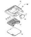
一方、表示ユニット50としては、本体ケース110に表示ユニット50を設ける一体型表示ユニット50と、本体ケース110とは別の位置に表示ユニットを配置する分離型表示ユニット50Bとが利用できる。図15に、一体型表示ユニット50の分解斜視図を示す。
(一体型表示ユニット50)
On the other hand, as the display unit 50, an integrated display unit 50 in which the display unit 50 is provided in the main body case 110 and a separate display unit 50B in which the display unit is disposed at a position different from the main body case 110 can be used. FIG. 15 is an exploded perspective view of the integrated display unit 50.
(Integrated display unit 50)

この図に示す一体型表示ユニット50は、フロントケース55と、電源ケーブル56と、表示基板57と、電源基板58とを備える。フロントケース55は、表示ユニット50の筐体であり、表示基板57を内部に保持すると共に、開口窓を通じて表示基板57上に設けられた7セグメント式表示器が外部に表出するように位置決めして固定する。また表示基板57の裏面には電源基板58が離間して配置される。電源ケーブル56は、容量式電磁流量計を駆動するための外部電源と接続されて、容量式電磁流量計に電力を供給する。表示基板57は、7セグメント式表示器や各種インジケータを構成するLED等の表示素子の駆動回路や、操作パネル54のスイッチ等を含む電子部品やCPU等の制御部品が実装されている。さらに、表示基板57と別に電源基板58が用意され、電源回路部品が電源基板58に実装される。表示用駆動回路を実装した表示基板57と、電源回路を実装した電源基板58とを分離することにより、電源回路の発熱を表示回路の電子部品から分離できる。
(択一固定機構)
The integrated display unit 50 shown in this figure includes a front case 55, a power cable 56, a display substrate 57, and a power substrate 58. The front case 55 is a housing of the display unit 50 and is positioned so that the display board 57 is held inside and a 7-segment display provided on the display board 57 is exposed to the outside through an opening window. And fix. Further, a power supply substrate 58 is disposed on the back surface of the display substrate 57 so as to be separated. The power cable 56 is connected to an external power source for driving the capacitive electromagnetic flow meter, and supplies power to the capacitive electromagnetic flow meter. The display board 57 is mounted with a drive circuit for a display element such as a LED constituting a 7-segment display and various indicators, an electronic component including a switch of the operation panel 54, and a control component such as a CPU. Further, a power supply board 58 is prepared separately from the display board 57, and power supply circuit components are mounted on the power supply board 58. By separating the display substrate 57 on which the display drive circuit is mounted from the power supply substrate 58 on which the power supply circuit is mounted, the heat generated in the power supply circuit can be separated from the electronic components of the display circuit.
(Alternative fixing mechanism)

表示ユニット50は、容量式電磁流量計の取り付け位置や姿勢に応じて、ユーザが表示画面52を目視しやすい姿勢に表示ユニット50の取り付け方向を変更可能としている。図16に、容量式電磁流量計の本体ケース110に、表示ユニット50を固定する様子を示す。図16(a)は、分離型表示ユニット50B、図16(b)は一体型表示ユニット50を固定する状態、非検出流体の流れ方向と水平に固定する状態、図16(c)は図16(b)と同じ一体型表示ユニット50を、非検出流体の流れ方向と垂直な姿勢に固定する状態を、それぞれ示している。   The display unit 50 can change the mounting direction of the display unit 50 so that the user can easily view the display screen 52 according to the mounting position and posture of the capacitive electromagnetic flow meter. FIG. 16 shows how the display unit 50 is fixed to the main body case 110 of the capacitive electromagnetic flow meter. 16A shows a separation type display unit 50B, FIG. 16B shows a state in which the integrated display unit 50 is fixed, a state in which the display unit 50 is fixed horizontally with the flow direction of the non-detection fluid, and FIG. The state where the same integrated display unit 50 as in (b) is fixed in a posture perpendicular to the flow direction of the non-detection fluid is shown.

具体的には、表示ユニット50及び本体ケース110上面の段差空間をほぼ正方形状として、表示ユニット50の取り付け角度を90°回転させても、固定可能としている。このため、表示ユニット50を本体ケース110上面に固定するための螺子孔122は、正確に四隅に穿孔されている。これにより、表示ユニット50を90°回転させた姿勢でも本体ケース110に固定でき、表示画面52の表示方向を変更できる。すなわち、被検出流体の流れ方向(例えば上下又は左右)に沿う姿勢に測定管10を固定すると共に、この容量式電磁流量計に固定する表示ユニット50の姿勢は、ユーザが表示画面52を目視しやすい方向に固定できる。   Specifically, the step space on the upper surface of the display unit 50 and the main body case 110 is substantially square, and the display unit 50 can be fixed even when the attachment angle of the display unit 50 is rotated by 90 °. For this reason, the screw holes 122 for fixing the display unit 50 to the upper surface of the main body case 110 are precisely drilled at the four corners. Accordingly, the display unit 50 can be fixed to the main body case 110 even when the display unit 50 is rotated by 90 °, and the display direction of the display screen 52 can be changed. That is, while the measuring tube 10 is fixed in a posture along the flow direction (for example, up and down or left and right) of the fluid to be detected, the posture of the display unit 50 fixed to the capacitive electromagnetic flow meter is determined by the user viewing the display screen 52. Can be fixed in an easy direction.

従来、容量式電磁流量計を配管等に固定する際、容量式電磁流量計が横置きの姿勢のみならず、縦置きの姿勢で固定されることもあった。この場合、表示器が縦方向に配置されるため、横書きで表示される数値が読みづらくなるという問題があった。一方、上述した特許文献2に示すように、縦横いずれの方向でも表示画面52を視認できるよう、表示ユニット50を本体ケース110と回転させる機構を備えた流量計も存在したが、回転機構が必要となり、その分構造が複雑となり、コストアップやサイズの大型化等の問題があった。これに対し、上記の構成では、取り付け姿勢を変更してねじ止めするという極めて簡単な構成であるため、部品点数が増えることもなく、小型化を実現しつつ、表示画面52が水平となるように、すなわちユーザが直立した姿勢から目視できる姿勢に、固定することができ、視認性がよくなる。   Conventionally, when a capacitive electromagnetic flow meter is fixed to a pipe or the like, the capacitive electromagnetic flow meter is sometimes fixed not only in a horizontal posture but also in a vertical posture. In this case, since the display device is arranged in the vertical direction, there is a problem that it is difficult to read numerical values displayed in horizontal writing. On the other hand, as shown in Patent Document 2 described above, there has been a flow meter provided with a mechanism for rotating the display unit 50 with the main body case 110 so that the display screen 52 can be visually recognized in both the vertical and horizontal directions, but a rotation mechanism is necessary. As a result, the structure is complicated, and there are problems such as an increase in cost and an increase in size. On the other hand, the above configuration is an extremely simple configuration in which the mounting posture is changed and screwed, so that the number of parts is not increased and the display screen 52 is made horizontal while achieving downsizing. In other words, it can be fixed to a posture that the user can see from an upright posture, and the visibility is improved.

なお、表示ユニット50を固定する方法は四隅の螺合に限られず、例えば正方形の各辺の中間に螺子孔を穿孔したり、フック等による係合や嵌合とすることもできる。   Note that the method of fixing the display unit 50 is not limited to screwing at the four corners. For example, a screw hole may be drilled in the middle of each side of the square, or engagement or fitting with a hook or the like.

また、必ずしも一の表示ユニットの取り付け角度を変更する構成に限られず、例えば水平方向表示用の表示ユニット、垂直方向表示用の表示ユニットを個別に用意し、用途に応じて適切な表示ユニットを選択して固定するように構成してもよい。この構成であれば90°回転可能な構成とする必要がないので、本体ケースの上面形状をほぼ正方形状とする必要がなく、本体ケースの形状を長方形状等様々な形状とすることができる利点が得られる。   In addition, it is not necessarily limited to the configuration in which the mounting angle of one display unit is changed. For example, a display unit for horizontal display and a display unit for vertical display are prepared separately, and an appropriate display unit is selected according to the application. And may be configured to be fixed. This configuration eliminates the need for a 90 ° rotatable configuration, so there is no need to make the upper surface of the main body case substantially square, and the main body case can have various shapes such as a rectangular shape. Is obtained.

さらに、本体ケース110に固定する表示ユニット50を交換式とできる。これにより、本体ケース110は一体型、分離型のいずれの表示ユニット50に対しても共通に使用でき、部材の共通化を図れるという利点が得られる。
(分離型表示ユニット50B)
Furthermore, the display unit 50 fixed to the main body case 110 can be replaced. As a result, the main body case 110 can be used in common for both the integral type and the separated type display unit 50, and the advantage that the members can be shared is obtained.
(Separate display unit 50B)

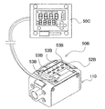
図16(a)は、分離型の表示ユニット50Bの一例を示している。分離型表示ユニット50Bは、図17に示すように表示画面52を本体ケース110から離間させて、本体ケース110には表示パネル50Cを配置し、ケーブル等により電気信号をやりとりして、本体ケース110と離れた位置で流量等の情報を表示画面52に表示する。表示パネル50Cは、上述した一体型表示ユニット50と同様の構成とできる。   FIG. 16A shows an example of a separate display unit 50B. As shown in FIG. 17, the separation type display unit 50 </ b> B separates the display screen 52 from the main body case 110, arranges the display panel 50 </ b> C in the main body case 110, and exchanges electric signals with cables or the like. Information such as the flow rate is displayed on the display screen 52 at a position away from The display panel 50C can have the same configuration as the integrated display unit 50 described above.

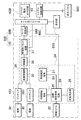
図18に、分離型表示ユニットを使用した電磁流量計200のブロック図を示す。この図に示す電磁流量計200は、本体ケースについては、上述した図3に係る一体型表示ユニットを使用した電磁流量計の本体ケース110と同じものが使用でき、詳細説明は省略する。図18のブロック図では、表示ユニット50Bに、A/D変換器38Bと、制御部40Cと、表示部として動作表示画面52Bと、出力部としてアナログ電流出力回路62Bと、通信部としてシリアル通信回路63を備える。シリアル通信回路63は、表示パネル50Cとデータ通信を行い、表示パネル50Cで表示すべき必要なデータを送信する。   FIG. 18 shows a block diagram of an electromagnetic flow meter 200 using a separate display unit. The electromagnetic flow meter 200 shown in this figure can use the same main body case as the main body case 110 of the electromagnetic flow meter using the integrated display unit according to FIG. 3 described above, and detailed description thereof will be omitted. In the block diagram of FIG. 18, the display unit 50B includes an A / D converter 38B, a control unit 40C, an operation display screen 52B as a display unit, an analog current output circuit 62B as an output unit, and a serial communication circuit as a communication unit. 63. The serial communication circuit 63 performs data communication with the display panel 50C and transmits necessary data to be displayed on the display panel 50C.

図16(a)の例では、7セグメント式表示器に代わって、本体ケース110の上面に動作表示画面52Bとして、被検出流体の通過を示すインジケータ53Bを設けている。動作表示画面52Bは、流量を検出中であること等、容量式電磁流量計の動作状態を示す他、被検出流体の移動方向を示すことができる。図16(a)の例ではインジケータ53Bとして、測定管10の検出方向に沿って矢印状の表示灯を4つ水平に並べており、LED等によって表示灯を点灯させる。インジケータ53Bは、被検出流体の通過方向に向かってインジケータ53Bを点滅させ、光を移動させるように点灯させることによって流れ方向を視覚的に表示する。   In the example of FIG. 16A, an indicator 53B indicating the passage of the fluid to be detected is provided as an operation display screen 52B on the upper surface of the main body case 110 instead of the 7-segment display. The operation display screen 52B can indicate the movement direction of the fluid to be detected in addition to the operation state of the capacitive electromagnetic flow meter, such as detecting the flow rate. In the example of FIG. 16A, as the indicator 53B, four arrow-shaped indicator lamps are arranged horizontally along the detection direction of the measuring tube 10, and the indicator lamps are turned on by LEDs or the like. The indicator 53B visually displays the flow direction by blinking the indicator 53B in the direction of passage of the fluid to be detected and lighting it so as to move the light.

例えば、検出方向に沿って被検出流体が流れている場合は表示灯を青色に点灯させ、一方被検出流体が逆方向に流れている場合は赤色に表示させる。また、表示灯の点滅パターンを動的に変化させて被検出流体の移動方向を表示させることで、さらに視覚的に流体の移動を容易に認識することができる。   For example, when the fluid to be detected is flowing along the detection direction, the indicator lamp is lit in blue, while when the fluid to be detected is flowing in the reverse direction, it is displayed in red. Further, by dynamically changing the blinking pattern of the indicator lamp to display the movement direction of the fluid to be detected, the movement of the fluid can be more easily recognized visually.

分離型表示ユニット50Bを構成する動作表示画面52Bの分解斜視図を図19に示す。この図に示す分離型表示ユニット50Bは、フロントケース55Bと、表示基板57Bと、電源基板58Bと、電源ケーブル56Bと、温度センサケーブル59Bとを備える。フロントケース55Bは、インジケータ53Bをインサート成形している。表示基板57Bや電源基板58Bは、上述した一体型表示ユニット50と同様の部品を実装して構成できる。さらにこの例では、被検出流体の温度を検出する温度センサからの入力信号を温度センサケーブル59Bを介して入力部70に入力し、被検出流体の温度を、離間して配置した表示パネル50C側に送出して表示させることもできる。   FIG. 19 shows an exploded perspective view of the operation display screen 52B constituting the separation type display unit 50B. The separation type display unit 50B shown in this figure includes a front case 55B, a display substrate 57B, a power supply substrate 58B, a power supply cable 56B, and a temperature sensor cable 59B. The front case 55B is insert-molded with the indicator 53B. The display board 57B and the power supply board 58B can be configured by mounting the same components as the integrated display unit 50 described above. Further, in this example, an input signal from a temperature sensor that detects the temperature of the fluid to be detected is input to the input unit 70 via the temperature sensor cable 59B, and the temperature of the fluid to be detected is arranged on the side of the display panel 50C that is spaced apart. Can be sent to and displayed.

なお、本体ケース上面の動作表示画面からインジケータを省いたり、逆に分離型表示ユニットであっても本体ケース側に流量等を表示する表示画面を設けること、すなわち表示ユニットを本体ケースと、それ以外の位置の2カ所に設けることも可能であることは言うまでもない。   In addition, omitting the indicator from the operation display screen on the top surface of the main body case, or conversely providing a display screen for displaying the flow rate etc. on the main body case side even if it is a separate display unit. Needless to say, it can also be provided at two positions.

本発明の容量式電磁流量計は、導電性液体の流量を検出する容量式電磁流量計として好適に適用できる。   The capacitive electromagnetic flow meter of the present invention can be suitably applied as a capacitive electromagnetic flow meter for detecting the flow rate of a conductive liquid.

流量センサの構成を示すブロック図である。It is a block diagram which shows the structure of a flow sensor. 本体ケースの断面図である。It is sectional drawing of a main body case. 容量式電磁流量計の詳細なブロック図である。It is a detailed block diagram of a capacitive electromagnetic flow meter. 本発明の一実施の形態に係る流量センサを示す斜視図である。It is a perspective view which shows the flow sensor which concerns on one embodiment of this invention. 図4に示す流量センサの表示ユニットを外した分解斜視図である。It is the disassembled perspective view which removed the display unit of the flow sensor shown in FIG. 図5の本体ケースから口金と補強板を外した分解斜視図である。It is a disassembled perspective view which removed the nozzle | cap | die and the reinforcement board from the main body case of FIG. サイドカバーを本体カバーで固定する状態を示す分解斜視図である。It is a disassembled perspective view which shows the state which fixes a side cover with a main body cover. ハウジングを本体カバーで保持する状態を示す断面図である。る。It is sectional drawing which shows the state holding a housing with a main body cover. The 測定管の斜視図及び電極を外した分解斜視図である。It is the perspective view of a measurement tube, and the exploded perspective view which removed the electrode. 図6の本体ケースの分解斜視図である。It is a disassembled perspective view of the main body case of FIG. プリアンプモジュールの分解斜視図である。It is a disassembled perspective view of a preamplifier module. 励磁モジュールの斜視図である。It is a perspective view of an excitation module. 励磁プレートの斜視図である。It is a perspective view of an excitation plate. 励磁コイルの分解斜視図である。It is a disassembled perspective view of an exciting coil. 一体型表示ユニットの分解斜視図である。It is a disassembled perspective view of an integrated display unit. 流量センサの本体ケースに、表示ユニットを固定する様子を示す斜視図である。It is a perspective view which shows a mode that a display unit is fixed to the main body case of a flow sensor. 分離型表示ユニットを使用した流量センサを示す斜視図である。It is a perspective view which shows the flow sensor which uses a separation type display unit. 分離型表示ユニットを使用した電磁流量計を示すブロック図である。It is a block diagram which shows the electromagnetic flowmeter which uses a separation type display unit. 分離型表示ユニットの分解斜視図である。It is a disassembled perspective view of a separation type display unit. 流量センサの他の構成を示すブロック図である。It is a block diagram which shows the other structure of a flow sensor.

符号の説明Explanation of symbols

100、200…電磁流量計
10、10B…測定管
12…突起
14…段差
22、22B…励磁コイル
24、24B…励磁回路
25…励磁電源
26…初期励磁電源
27…励磁継続電源
28…励磁極性切替回路
29…定電流回路
30、30B…電極
32…リード片
34、34B…検出回路
35…差動増幅器
36…増幅器
37…周期性リセット回路
38、38B…A/D変換器
40、40B、40C…制御部
42…メモリ部
50…表示ユニット
50B…分離型表示ユニット
50C…表示パネル
51、51B…表示部
52…表示画面
52B…動作表示画面
53…流体表示灯
53B…インジケータ
54…操作パネル
55、55B…フロントケース
56、56B…電源ケーブル
57、57B…表示基板
58、58B…電源基板
59B…温度センサケーブル
60…出力部
61…外部出力回路
62、62B…アナログ電流出力回路
63…シリアル通信回路
70…入力部
80…設定部
110…本体ケース
111…流路口
112…螺子溝
120…ハウジング
121…貫通孔
122…螺子孔
130…サイドカバー
140…ヨーク蓋
142…補強板
144…液アース端子
150、151、152、153…本体カバー
155…側板
156…螺子孔
160…プリアンプモジュール
161…シールドケース
162…シールドカバー
163…プリアンプ
164…プリアンプ基板
165…プリアンプ基板ホルダ
166…電極保護シート
170…励磁モジュール
172…コイルケース
172a、172b…平板
172c…コイル捲回空間
172d…ポールピース挿入口
174…励磁プレート
174a…対向片
174b…連結片
174c…ヨーク片
174d…開口部
176…中継基板
178…ポールピース
178a…ポールピースコア
178b…平板
178B…コア
DESCRIPTION OF SYMBOLS 100, 200 ... Electromagnetic flowmeter 10, 10B ... Measuring tube 12 ... Protrusion 14 ... Level difference 22, 22B ... Excitation coil 24, 24B ... Excitation circuit 25 ... Excitation power source 26 ... Initial excitation power source 27 ... Excitation continuing power source 28 ... Excitation polarity switching Circuit 29 ... Constant current circuit 30, 30B ... Electrode 32 ... Lead piece 34, 34B ... Detection circuit 35 ... Differential amplifier 36 ... Amplifier 37 ... Periodic reset circuit 38, 38B ... A / D converters 40, 40B, 40C ... Control unit 42 ... Memory unit 50 ... Display unit 50B ... Separate display unit 50C ... Display panel 51, 51B ... Display unit 52 ... Display screen 52B ... Operation display screen 53 ... Fluid display lamp 53B ... Indicator 54 ... Operation panel 55, 55B ... Front case 56, 56B ... Power cable 57, 57B ... Display board 58, 58B ... Power board 59 ... temperature sensor cable 60 ... output part 61 ... external output circuit 62, 62B ... analog current output circuit 63 ... serial communication circuit 70 ... input part 80 ... setting part 110 ... main body case 111 ... flow path port 112 ... screw groove 120 ... housing 121 ... through hole 122 ... screw hole 130 ... side cover 140 ... yoke lid 142 ... reinforcing plate 144 ... liquid earth terminals 150, 151, 152, 153 ... body cover 155 ... side plate 156 ... screw hole 160 ... preamplifier module 161 ... shield case 162 Shield cover 163 Preamplifier 164 Preamplifier substrate 165 Preamplifier substrate holder 166 Electrode protection sheet 170 Excitation module 172 Coil cases 172a and 172b Flat plate 172c Coil winding space 172d Pole piece insertion port 174 Excitation plate 74a ... facing plate 174b ... connecting piece 174c ... yoke pieces 174d ... opening 176 ... relay board 178 ... pole pieces 178a ... Paul P. score 178b ... flat 178B ... core

Claims (5)

被検出流体の流量を検出するための容量式電磁流量計であって、
本体ケースと、
前記本体ケース内に配設されて被検出流体を通過させるための測定管と、
被検出流体に交番磁場を印加するための磁場印加手段と、
被検出流体と非接触となるよう前記測定管と結合される電極と、
前記測定管を通過する被検出流体の流量を演算する演算手段と、
を備え、
前記測定管を前記本体ケースと別部材で構成し、交換可能としたことを特徴とする容量式電磁流量計。
A capacitive electromagnetic flow meter for detecting the flow rate of a fluid to be detected,
A body case,
A measuring tube disposed in the main body case for passing a fluid to be detected;
Magnetic field application means for applying an alternating magnetic field to the fluid to be detected;
An electrode coupled to the measuring tube so as to be in non-contact with the fluid to be detected;
A computing means for computing the flow rate of the fluid to be detected passing through the measuring tube;
With
A capacity type electromagnetic flow meter characterized in that the measuring tube is constituted by a member separate from the main body case and is replaceable.
請求項1に記載の容量式電磁流量計であって、
前記測定管が前記本体ケースと異なる部材で構成されてなることを特徴とする容量式電磁流量計。
The capacitive electromagnetic flow meter according to claim 1,
The capacity type electromagnetic flow meter, wherein the measuring tube is made of a member different from the main body case.
請求項1に記載の容量式電磁流量計であって、
前記測定管が高誘電性の樹脂部材で構成されてなることを特徴とする容量式電磁流量計。
The capacitive electromagnetic flow meter according to claim 1,
A capacity type electromagnetic flow meter, wherein the measuring tube is made of a high dielectric resin member.
被検出流体の流量を検出するための容量式電磁流量計であって、
本体ケースと、
前記本体ケース内に配設されて被検出流体を通過させるための測定管と、
被検出流体に交番磁場を印加するための磁場印加手段と、
被検出流体と非接触となるよう前記測定管と結合される電極と、
前記測定管を通過する被検出流体の流量を演算する演算手段と、
前記演算手段で演算された被検出流体の流量を表示可能な表示部と、
を備え、
前記表示部を前記本体ケースに固定する構造が、被検出流体の流れる方向に対して、前記表示部を水平又は垂直のいずれかとなるよう前記本体ケースに取り付け可能に構成してなることを特徴とする容量式電磁流量計。
A capacitive electromagnetic flow meter for detecting the flow rate of a fluid to be detected,
A body case,
A measuring tube disposed in the main body case for passing a fluid to be detected;
Magnetic field application means for applying an alternating magnetic field to the fluid to be detected;
An electrode coupled to the measuring tube so as to be in non-contact with the fluid to be detected;
A computing means for computing the flow rate of the fluid to be detected passing through the measuring tube;
A display unit capable of displaying the flow rate of the fluid to be detected calculated by the calculation means;
With
The structure for fixing the display unit to the main body case is configured to be attachable to the main body case so that the display unit is either horizontal or vertical with respect to the direction of flow of the fluid to be detected. Capacitive electromagnetic flow meter.
請求項4に記載の容量式電磁流量計であって、
前記表示部の外形が略正方形状に形成されてなり、四隅をねじ止めにより前記ケース部に固定可能に構成してなることを特徴とする容量式電磁流量計。
It is a capacity type electromagnetic flow meter according to claim 4,
A capacity type electromagnetic flow meter, wherein the outer shape of the display part is formed in a substantially square shape, and the four corners can be fixed to the case part by screwing.
JP2006126765A 2006-04-28 2006-04-28 Capacitive electromagnetic flowmeter Pending JP2007298402A (en)

Priority Applications (1)

Application Number Priority Date Filing Date Title
JP2006126765A JP2007298402A (en) 2006-04-28 2006-04-28 Capacitive electromagnetic flowmeter

Applications Claiming Priority (1)

Application Number Priority Date Filing Date Title
JP2006126765A JP2007298402A (en) 2006-04-28 2006-04-28 Capacitive electromagnetic flowmeter

Publications (2)

Publication Number Publication Date
JP2007298402A true JP2007298402A (en) 2007-11-15
JP2007298402A5 JP2007298402A5 (en) 2009-05-21

Family

ID=38768011

Family Applications (1)

Application Number Title Priority Date Filing Date
JP2006126765A Pending JP2007298402A (en) 2006-04-28 2006-04-28 Capacitive electromagnetic flowmeter

Country Status (1)

Country Link
JP (1) JP2007298402A (en)

Cited By (7)

* Cited by examiner, † Cited by third party
Publication number Priority date Publication date Assignee Title
JP2009258003A (en) * 2008-04-18 2009-11-05 Smc Corp Electromagnetic flowmeter
KR101108105B1 (en) * 2008-04-18 2012-01-31 에스엠씨 가부시키 가이샤 Electromagnetic flowmeter
JP2014238418A (en) * 2014-08-06 2014-12-18 株式会社タツノ Portable type flowmeter
KR20190108060A (en) * 2018-03-13 2019-09-23 아즈빌주식회사 Electromagnetic flowmeter
KR20190108062A (en) 2018-03-13 2019-09-23 아즈빌주식회사 Excitation circuit of electromagnetic flowmeter and electromagnetic flowmeter
JP2020186933A (en) * 2019-05-10 2020-11-19 アズビル株式会社 Capacitive type electromagnetic flowmeter
CN114130563A (en) * 2019-11-04 2022-03-04 深圳市大疆创新科技有限公司 Electromagnetic flowmeter, sprinkling system and unmanned aerial vehicle

Citations (4)

* Cited by examiner, † Cited by third party
Publication number Priority date Publication date Assignee Title
JPS5826622U (en) * 1981-08-14 1983-02-21 横河電機株式会社 electromagnetic flowmeter transmitter
JPS6170416A (en) * 1984-09-14 1986-04-11 Yamatake Honeywell Co Ltd Electromagnetic flowmeter detector and its production
JPS6333135Y2 (en) * 1980-09-04 1988-09-05
JP2005121656A (en) * 2003-10-10 2005-05-12 Abb Patent Gmbh Magnetic inductive measuring instrument for flowing substance, and method of manufacturing the measuring instrument

Patent Citations (4)

* Cited by examiner, † Cited by third party
Publication number Priority date Publication date Assignee Title
JPS6333135Y2 (en) * 1980-09-04 1988-09-05
JPS5826622U (en) * 1981-08-14 1983-02-21 横河電機株式会社 electromagnetic flowmeter transmitter
JPS6170416A (en) * 1984-09-14 1986-04-11 Yamatake Honeywell Co Ltd Electromagnetic flowmeter detector and its production
JP2005121656A (en) * 2003-10-10 2005-05-12 Abb Patent Gmbh Magnetic inductive measuring instrument for flowing substance, and method of manufacturing the measuring instrument

Cited By (14)

* Cited by examiner, † Cited by third party
Publication number Priority date Publication date Assignee Title
JP2009258003A (en) * 2008-04-18 2009-11-05 Smc Corp Electromagnetic flowmeter
JP4721073B2 (en) * 2008-04-18 2011-07-13 Smc株式会社 Electromagnetic flow meter
KR101108105B1 (en) * 2008-04-18 2012-01-31 에스엠씨 가부시키 가이샤 Electromagnetic flowmeter
US8127622B2 (en) 2008-04-18 2012-03-06 Smc Kabushiki Kaisha Electromagnetic flowmeter having a detachable measuring tune from the body
TWI407083B (en) * 2008-04-18 2013-09-01 Smc Kk Electromagnetic flowmeter
JP2014238418A (en) * 2014-08-06 2014-12-18 株式会社タツノ Portable type flowmeter
KR20190108060A (en) * 2018-03-13 2019-09-23 아즈빌주식회사 Electromagnetic flowmeter
KR20190108062A (en) 2018-03-13 2019-09-23 아즈빌주식회사 Excitation circuit of electromagnetic flowmeter and electromagnetic flowmeter
US10527472B2 (en) 2018-03-13 2020-01-07 Azbil Corporation Excitation circuit for electromagnetic flowmeter, and electromagnetic flowmeter
KR102109914B1 (en) 2018-03-13 2020-05-12 아즈빌주식회사 Electromagnetic flowmeter
JP2020186933A (en) * 2019-05-10 2020-11-19 アズビル株式会社 Capacitive type electromagnetic flowmeter
JP7294875B2 (en) 2019-05-10 2023-06-20 アズビル株式会社 capacitive electromagnetic flowmeter
CN114130563A (en) * 2019-11-04 2022-03-04 深圳市大疆创新科技有限公司 Electromagnetic flowmeter, sprinkling system and unmanned aerial vehicle
CN114130563B (en) * 2019-11-04 2023-05-23 深圳市大疆创新科技有限公司 Electromagnetic flowmeter, spraying system and unmanned aerial vehicle

Similar Documents

Publication Publication Date Title
JP5065620B2 (en) Electromagnetic flow meter
JP4919702B2 (en) Sensor device and sensor system
JP2007298402A (en) Capacitive electromagnetic flowmeter
JP5102463B2 (en) Flow sensor
TWI608402B (en) Electronic apparatus
US8127622B2 (en) Electromagnetic flowmeter having a detachable measuring tune from the body
JP2014202662A (en) Electromagnetic flowmeter
JP2018525626A5 (en)
KR20070083660A (en) Electrical-energy meter adaptable for optical communication with various external devices
JP2007315812A (en) Flow sensor
JP2007298400A (en) Flow sensor
US9658088B2 (en) Flow measuring device, measuring tube as well as method for manufacture of a flow measuring device
CN111351534A (en) Flow nonmagnetic metering device
CN111094905A (en) Magnetic induction flowmeter
JP2007298403A (en) Analog current output circuit for detection sensor, and detection sensor provided with alalog current output circuit
CN110823299B (en) Novel impeller electromagnetic flowmeter
JP2019158584A (en) Electromagnetic flowmeter
WO2018138518A1 (en) Electromagnetic flow sensor
CN209927194U (en) High-precision electromagnetic water meter
KR101108105B1 (en) Electromagnetic flowmeter
CN111771104B (en) Electromagnetic flowmeter
WO2012137389A1 (en) Current detecting apparatus and voltmeter
CN2909179Y (en) Magnetic resistance direct read meter
KR20090093328A (en) Measuring instrument
CN213363900U (en) Flow nonmagnetic metering device

Legal Events

Date Code Title Description
A521 Written amendment

Free format text: JAPANESE INTERMEDIATE CODE: A523

Effective date: 20090401

A621 Written request for application examination

Free format text: JAPANESE INTERMEDIATE CODE: A621

Effective date: 20090401

A131 Notification of reasons for refusal

Free format text: JAPANESE INTERMEDIATE CODE: A131

Effective date: 20120207

A02 Decision of refusal

Free format text: JAPANESE INTERMEDIATE CODE: A02

Effective date: 20120605