JP2007281145A - Flexible wiring member - Google Patents
Flexible wiring member Download PDFInfo
- Publication number
- JP2007281145A JP2007281145A JP2006104477A JP2006104477A JP2007281145A JP 2007281145 A JP2007281145 A JP 2007281145A JP 2006104477 A JP2006104477 A JP 2006104477A JP 2006104477 A JP2006104477 A JP 2006104477A JP 2007281145 A JP2007281145 A JP 2007281145A
- Authority
- JP
- Japan
- Prior art keywords
- pattern
- shield
- wiring
- fpc
- line
- Prior art date
- Legal status (The legal status is an assumption and is not a legal conclusion. Google has not performed a legal analysis and makes no representation as to the accuracy of the status listed.)
- Pending
Links
Images


Abstract
Description
本発明は、電磁波遮蔽層としてシールド用配線パターンを備えるフレキシブルプリント配線板(FPC:Flexible Printed Circuits )、フレキシブルフラットケーブル(FFC:Flexible Flat Cable)などのフレキシブル配線体に係り、より詳細には、繰り返し折り曲げ応力や摺動によるシールドパターン配線の断線を防止して、屈曲強度と可撓性を向上させることができるフレキシブル配線体に関するものである。 The present invention relates to a flexible printed circuit board (FPC: Flexible Printed Circuits) having a wiring pattern for shielding as an electromagnetic wave shielding layer, a flexible flat cable (FFC), and the like. The present invention relates to a flexible wiring body that can prevent bending of a shield pattern wiring due to bending stress or sliding to improve bending strength and flexibility.
近年は、携帯電話機・パーソナルコンピュータ・カメラ・ラジオカセット等の電子機器においては、ユーザらの要望から、益々装置の小型化、軽量化および薄型化への移行が進んでいる。このため、これらの機器の内部に使用されているプリント配線板およびケーブル類も、小型軽量で薄型のフレキシブルプリント配線板(FPC)およびフレキシブルフラットケーブル(FFC)が用いられている。 In recent years, electronic devices such as mobile phones, personal computers, cameras, and radio cassettes have been increasingly shifted to smaller, lighter, and thinner devices due to user demands. For this reason, the printed wiring boards and cables used in these devices are also small, lightweight and thin flexible printed wiring boards (FPC) and flexible flat cables (FFC).
これらの機器に用いられるフレキシブルプリント配線板およびフレキシブルフラットケーブルなどの配線体では、外部および内部からのノイズに対して遮蔽対策を施さねばならない。遮蔽(シールド)をしないと、ノイズによって信号が影響を受け、本来の電送特性が低下してしまい、製品への障害が発生する虞があるためである。 Wiring bodies such as flexible printed wiring boards and flexible flat cables used in these devices must be shielded against external and internal noise. This is because if the shielding is not performed, the signal is affected by noise, the original power transmission characteristics are deteriorated, and the product may be damaged.
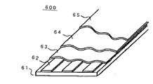
図6は、従来のフレキシブルプリント配線板(FPC)の構造例を外観斜視により示す説明図である。ここでのFPC600は、シリカ、紙、漆、膠等の動植物繊維や生分解性プラスチック、難燃性ポリオレフィン、ポリエステルなどの材料を薄板状に形成したベース基材61を備えており、この上には第一の金属層62が設けられる。この金属層62は、プリント技術などを用いて形成された導体パターン(信号パターン)が形成された導体パターン層62である。また、この導体パターン層62は、ポリイミド・ポリエステル等の絶縁被膜層(カバーレイ)63によって被膜されており、この絶縁被膜層63の上は第二の金属層64が設けられる。
FIG. 6 is an explanatory view showing a structural example of a conventional flexible printed wiring board (FPC) in an external perspective view. The FPC 600 here includes a base substrate 61 in which materials such as silica, paper, lacquer, glue, and other animal and plant fibers, biodegradable plastics, flame retardant polyolefin, and polyester are formed in a thin plate shape. Is provided with a
この第二金属層64は、外部からのノイズ遮断を行う電磁波遮蔽層すなわちシールド層64であって、例えば、プリント技術を用いて銅・銀またはカーボンの導電性ペースト(電磁波遮蔽層)を、ベタ塗りまたはメッシュ状にして印刷した後、これを熱硬化処理させて形成することができる。さらに、このシールド層64を保護するために、その上にポリイミド・ポリエステル等からなる保護層65(カバーレイ)を設けている。
The
本願発明のようなシールド層を備えるフレキシブル配線体に関連する技術分野においては、たとえば次のような特許文献が公知である。
ここで図3〜5を用いて、従来から用いられているフレキシブルプリント配線板(FPC)のシールド構造例について具体的に説明する。
図3はFPCのシールド構造の第一の例であり、FPC300は内部に配線ライン(ラインパターン)LP3を有する長尺平板形状の可撓性ケーブルであり、その中央部はややくびれていて、そのラインパターンの周りには、アルミ蒸着シートや銅箔シートなどの遮蔽用シートST3を巻きつけて、これによってシールド層を形成している。
Here, an example of a shield structure of a flexible printed wiring board (FPC) conventionally used will be specifically described with reference to FIGS.
FIG. 3 shows a first example of the shield structure of the FPC, and the FPC 300 is a long flat plate-like flexible cable having a wiring line (line pattern) LP3 inside, and its central portion is slightly constricted. A shielding sheet ST3 such as an aluminum vapor deposited sheet or a copper foil sheet is wound around the line pattern, thereby forming a shield layer.
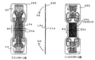
図4は、FPCのシールド構造の第二の例であり、このFPC400は、表面側にはラインパターンLP4が、裏面側にはシールドパターンSP4が併設されて配線された長尺平板形状の可撓性ケーブル体であって、ここでのシールドパターンSP4はベタグランド構造からなるシールドパターンとなっている。
また図5は、FPCのシールド構造の第三の例であり、FPC500は、表面側にはラインパターンLP5が裏面側にはシールドパターンSP5が併設されて配線された長尺平板形状の可撓性ケーブル体であって、ここでのシールドパターンSP5はメッシュ構造によるシールドパターンとなっている。
FIG. 4 shows a second example of the shield structure of the FPC. The FPC 400 has a long plate-like flexible wiring in which a line pattern LP4 is provided on the front side and a shield pattern SP4 is provided on the back side. The shield pattern SP4 here is a shield pattern having a solid ground structure.
FIG. 5 shows a third example of the shield structure of the FPC. The FPC 500 has a long plate-like flexible structure in which a line pattern LP5 is provided on the front side and a shield pattern SP5 is provided on the back side. It is a cable body, Comprising: The shield pattern SP5 here is a shield pattern by a mesh structure.
つぎに従来のFPCにおけるシールド構造の問題点について述べる。
図3のFPC300では、配線ラインの周りに巻きつけるアルミ蒸着シートや銅箔シートなどの遮蔽用シートST1が別途必要になるので、部品点数が増加する、取り付け作業の工程がさらに増える、などによるコストアップが問題となる。
また、図4のFPC400と図5のFPC500では、FPCの配線ライン(ラインパターン)の裏面に、ベタグラント構造またはメッシュ構造のシールド用ラインパターンを併設するものであるが、両面FPCのラインパターンは、銅箔とスルーホールメッキ(銅メッキ)とから構成されており、ライン数が多い程、またラインが太い程、FPCの剛性が上がってしまい、FPC本来の特徴であるフレキシブル性(可撓性)の性能が発揮できなくなる。
Next, problems of the shield structure in the conventional FPC will be described.
In the FPC 300 of FIG. 3, a shielding sheet ST1 such as an aluminum vapor-deposited sheet or a copper foil sheet to be wound around the wiring line is separately required, so that the number of parts increases and the cost of the mounting work increases. Up is a problem.
Further, in the FPC 400 of FIG. 4 and the FPC 500 of FIG. 5, a shield line pattern having a tagurant structure or a mesh structure is provided on the back surface of the FPC wiring line (line pattern). It is composed of copper foil and through-hole plating (copper plating). The greater the number of lines and the thicker the line, the more rigid the FPC will be. ) Performance cannot be demonstrated.
そして、FPC400とFPC500のようなベタグラント構造またはメッシュ構造のシールド用パターンを備える可撓性ケーブルでは、これを曲げるときの曲げ方向に対しては、シールドパターンが平行あるいは交差するような配線パターンとなっており、そのため、FPCを曲げる際には、パターンから引っ張られる(あるいは縮められる)方向に大きな力が発生することにより、パターン断線に至りやすくなるという問題がある。 In a flexible cable having a shield pattern having a tagrant structure or a mesh structure such as FPC 400 and FPC 500, a wiring pattern in which the shield pattern is parallel or intersects with respect to the bending direction when bending the cable. Therefore, when bending the FPC, a large force is generated in a direction in which the FPC is pulled (or contracted), and thus there is a problem that the pattern is likely to be disconnected.
図4のFPC400についてより詳しく述べる。 このFPC400は、主部A4−中間部B4−主部C4とからなる長尺平板形状の可撓性ケーブル体であり、中間部B4が折り曲げ部となっている。曲げ方向(D4とD4’)に応力がかけられると、折り曲げ部B4において折り曲げられ、その折り曲げ部B4には多くの折り曲げ線BS4が生じるが、これらの折り曲げ線BS4は、曲げ方向(D4−D4’)に直交するかそれに角度をもって交差される線となる。そして、このFPC400のシールドパターンSP4は、折り曲げられるときは外側となって、内側にあるラインパターンLP4よりも大きな曲率半径を有するので、より大きな引っ張り応力がかかって、シールドパターンの断線が起こりやすい構造となっている。 The FPC 400 in FIG. 4 will be described in more detail. The FPC 400 is a long flat plate-shaped flexible cable body including a main part A4-intermediate part B4-main part C4, and the intermediate part B4 is a bent part. When stress is applied in the bending directions (D4 and D4 ′), the bending portion B4 is bent, and a large number of bending lines BS4 are generated in the bending portion B4. The bending lines BS4 are bent in the bending direction (D4-D4). It is a line perpendicular to ') or intersected with an angle. The shield pattern SP4 of the FPC 400 becomes the outer side when bent, and has a larger radius of curvature than the line pattern LP4 on the inner side, so that a greater tensile stress is applied and the shield pattern is likely to break. It has become.
本願発明では上記の問題点に鑑みてなされたものであって、アルミ蒸着シートや銅箔シートなどの別部品からなるシールド用シートが必要ではないシールド構造、確実なシールド性を確保しつつ、繰り返しの屈曲/ひねり/引っ張り/摺動などの動作に伴う応力が加わっても、シールトパターンが容易に断線することがなく、シールド性とフレキシブル性を両立させることができるシールド構造、を備えるフレキシブル配線体を提供することを目的としている。 The present invention has been made in view of the above-mentioned problems, and does not require a shield sheet made of a separate part such as an aluminum vapor-deposited sheet or a copper foil sheet. Flexible wiring comprising a shield structure that can achieve both shielding properties and flexibility without easily breaking the sealed pattern even when stresses associated with operations such as bending, twisting, pulling, and sliding are applied The purpose is to provide a body.
(1)ラインパターンとシールドパターンとが併設配線される長尺平板形状のフレキシブル配線体において、
前記フレキシブル配線体は、前記ラインパターンの配線方向と交差する位置に折り曲げ部を有し、
前記折り曲げ部は、折り曲げ方向と直交する折り曲げ線を有し、
前記シールドパターンは、前記折り曲げ部において前記折り曲げ線と平行する配線を備えて構成される。
(1) In a long flat flexible wiring body in which a line pattern and a shield pattern are wired together,
The flexible wiring body has a bent portion at a position intersecting the wiring direction of the line pattern,
The folding portion has a folding line orthogonal to the folding direction;
The shield pattern includes a wiring parallel to the fold line at the fold portion.
(2)(1)のフレキシブル配線体において、
前記シールドパターンは、前記折り曲げ部において、前記折り曲げ線に平行する配線と前記折り曲げ線と交差する配線とを備えて構成される。
(3)(2)のフレキシブル配線体において、
前記シールドパターンは、前記折り曲げ線に平行する複数の配線と、前記折り曲げ線と直交する少なくとも2本の配線とにより、梯子状のパターンに構成される。
(4)(1)のフレキシブル配線体において、
前記シールドパターンは、前記折り曲げ部における配線パターンと、前記折り曲げ部以外における配線パターンとを備え、
前記折り曲げ部以外における配線パターンは、メッシュ状パターンまたはベタグランドパターンによって構成される。
(2) In the flexible wiring body of (1),
The shield pattern includes a wiring parallel to the fold line and a wiring intersecting with the fold line in the bent portion.
(3) In the flexible wiring body of (2),
The shield pattern is configured in a ladder pattern by a plurality of wirings parallel to the folding line and at least two wirings orthogonal to the folding line.
(4) In the flexible wiring body of (1),
The shield pattern includes a wiring pattern in the bent portion, and a wiring pattern other than the bent portion,
The wiring pattern other than the bent portion is constituted by a mesh pattern or a solid ground pattern.
本願発明によるフレキシブル配線体では、ラインパターンの配線方向と交差する位置に折り曲げ部を有し、その折り曲げ部は折り曲げ方向と直交する折り曲げ線を有し、シールドパターンはその折り曲げ部において前記折り曲げ線と平行する配線を備えて構成されている。そのため、シールドパターンの折り曲げ線と平行する配線は、折り曲げ時においても引っ張り応力を受けることがなく、また、フレキシブル配線体自体が折り曲げ時に硬くなることもなく、シールドパターンの断線は起こり難くなり、シールド性とフレキシブル性とを両立させることができるシールド構造を備えるフレキシブル配線体を提供することができる。 In the flexible wiring body according to the present invention, there is a bent portion at a position intersecting with the wiring direction of the line pattern, the bent portion has a folding line orthogonal to the bending direction, and the shield pattern has the bending line at the bent portion. It is configured with parallel wiring. Therefore, the wiring parallel to the fold line of the shield pattern is not subjected to tensile stress even when bent, and the flexible wiring body itself does not become hard when bent, and the shield pattern is less likely to break. Therefore, it is possible to provide a flexible wiring body having a shield structure capable of satisfying both properties and flexibility.
さて、本発明によるフレキシブル配線体の実施の形態について、図1(第1の実施の形態)と図2(第2の実施の形態)を参照して説明する。
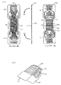
図1(1)は、主部A1−中間部B1(折り曲げ部)−主部C1とからなる長尺平板形状の可撓性ケーブル体であるFPC100を、表面/側面/背面(裏面)の3方向からみた外観図である。FPC100は、その一方の面側(表面側)にはラインパターンLP1が長手方向に添って配線されており、中間部B1を経由して主部A1(上部)と主部C1(下部)とが電気的に接続されている。また、他方の面側(裏面側)にはラインパターンLP1と併設されてシールドパターンSP1が配線されており、主部A1(上部)と主部C1((下部)とが中間部B1を経由して電気的に接続されている。
Now, an embodiment of the flexible wiring body according to the present invention will be described with reference to FIG. 1 (first embodiment) and FIG. 2 (second embodiment).
FIG. 1 (1) shows an FPC 100, which is a long flat-plate-shaped flexible cable body composed of a main part A1-intermediate part B1 (bent part) -main part C1, in a front / side / back (back) side. It is the external view seen from the direction. In the
図1(2)は、図1(1)のFPC100を曲げ方向(D1とD1’)に応力をかけて曲げたときの様子を示す説明図である。図1(1)のFPC100は、折り曲げ部B1において折り曲げられるが、その折り曲げ部B1には多くの折り曲げ線BS1が生じ、これらの折り曲げ線BS1は、曲げ方向(D1−D1’)に直交するかそれに角度をもって交差される線となる。そして、このFPC100のシールドパターンSP1は、図1(1)のように折り曲げられるときは、折り曲げ部B1の外側に位置していて、内側にあるラインパターンLP1よりも大きな曲率半径を有するので、より大きな引っ張り応力がかかりやすい構造となっている。
FIG. 1 (2) is an explanatory view showing a state when the
図1(1)において、FPC100のシールドパターンSP1の配線構造は、折り曲げ部B1における多数の折り曲げ線BS1と平行する多数の横配線(y1〜y12)と、直交する両端2本の縦配線(x1、x2)とから構成され、全体としては「梯子(はしご)状」を成している。ここでの縦配線(x1、x2)は、FPC100の折り曲げ方向(D1とD1’)に略平行に配設されるグランドライン(シールドライン)であり、横配線(y1〜y12)は縦配線(x1、x2)を繋ぐグランドライン(シールドライン)であって、FPC100の折り曲げ方向(D1とD1’)に略垂直にして配設されたラインとなっている。
In FIG. 1A, the wiring structure of the shield pattern SP1 of the
図1(1)のFPC100のシールドパターンSP1の配線は、ラインパターンの配線方向と交差する位置に折り曲げ部B1を有し、その折り曲げ部B1は折り曲げ方向と直交する折り曲げ線BS1を有し、シールドパターンSP1はその折り曲げ部B1において前記折り曲げ線と平行する多くの配線(横配線:y1〜y12)を備えて構成されている。そのため、シールドパターンSP1の横配線(y1〜y12)は、折り曲げ時においても引っ張り方向のストレスを受けることがなく、シールドパターンSP1の断線は起こり難くなっている。また、フレキシブル配線体(FPC100)自体が折り曲げ時に硬くなることもなく、シールド性とフレキシブル性とを両立させることができるシールド構造を備えるフレキシブル配線体100が得られる。
The wiring of the shield pattern SP1 of the
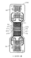
つぎの図2は、FPC100とは異なるシールド構造を有するFPC200を背面(裏面、シールドパターン側)の方向からみた外観図である。ここでのFPC200は、主部A2−中間部B2(折り曲げ部)−主部C2とからなる長尺平板形状の可撓性ケーブル体であるのはFPC100と同様であるが、このFPC200の裏面側には別のシールドパターンSP2が配線されており、主部A2(上部)と主部C2((下部)とが中間部B2(折り曲げ部)を経由して電気的に接続されている。
Next, FIG. 2 is an external view of the
図2において、FPC200の折り曲げ部B2におけるシールドパターンSP2の配線は、パターンP1とP2とP3とが平板状に一体的に組み合わされた構造「P1+P2+P3」からなるものであり、パターンP1とP3とは同じメッシュ構造によるシールドパターンからなり、パターンP2は図1のシールドパターンSP1と同様の梯子状シールド構造からなるものが用いられている。
In FIG. 2, the wiring of the shield pattern SP2 in the bent portion B2 of the
折り曲げ部B2の中心部にあるパターンP2は、折り曲げ線BS2と平行する複数の横配線(y22、y22)と、それに直交する両端2本の縦配線(x21、x22)とから構成されていて、全体としては低い「梯子(はしご)状」のシールド構造を成している。また、このFPC200では、パターンP2の両端側(上下部)には従来のシールド構造によるパターン(P1とP3)を平面的に連結接続して組み合わせたものであり、折り曲げ部B2の実質的な折り曲げ個所として広い面積を確保する必要のないときには、パターンP2の個所だけを「梯子(はしご)状」のシールド構造に形成することができる。なお、ここでは、メッシュ構造によるシールドパターンを採用したが、ベタグランド構造によるシールドパターンを用いてもよい。
The pattern P2 at the center of the bent part B2 is composed of a plurality of horizontal wirings (y22, y22) parallel to the bending line BS2, and two vertical wirings (x21, x22) at both ends orthogonal to the pattern P2. The overall structure is a low “ladder” shield structure. Further, in this
これまでは、本発明によるフレキシブル配線体を、フレキシブルプリント配線板(FPC:Flexible Printed Circuits )に適用する例について主に述べてきたが、他のフレキシブル配線体、例えばフレキシブルフラットケーブル(FFC:Flexible Flat Cable)についても適用することが可能である。 So far, examples of applying the flexible wiring body according to the present invention to flexible printed circuit boards (FPC) have been mainly described. However, other flexible wiring bodies such as a flexible flat cable (FFC: Flexible Flat Cable) are described. (Cable) is also applicable.
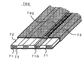
図7は、フレキシブルフラットケーブル(FFC)の構造例を外観斜視により示す説明図である。このFFC700は、導体パターン71を絶縁被膜層72でフラットケーブル形状になるように絶縁被膜し、次に、導体パターン71中のグランド線71Gの部分の絶縁被膜層72のみを剥離した後、アクリル系導電性の粘着剤付きの銅箔(またはアルミニウム箔等)で全体を覆うように巻き付けて電磁波遮蔽層73を形成したものである。このような構造のFFC700では、ケーブル自体の曲げやひねり等のストレスによって、ノイズ遮断のための金属箔がとれてしまわないように、電磁波遮蔽層73とグランド線71とを強く接続させて接合力を高めておく必要がある。
FIG. 7 is an explanatory view showing a structural example of a flexible flat cable (FFC) by an external perspective view. In this
図7のFPC700は、中心部にはラインパターン71(導体パターン)を、表面側にはシールドパターン73を有する長尺平板形状のフレキシブルケーブルである。このFPC700は、ラインパターン71の配線方向と交差する位置において折り曲げ部(図示せず)を有し、その折り曲げ部は、折り曲げ方向と直交する折り曲げ線(図示せず)を有している。そして、FPC700の表面に配設されたシールドパターン73として、その折り曲げ部において、折り曲げ線と平行する配線を備えさせれば、図1または図2のシールドパターンと同様のシールド構造として形成されることができる。
The
100、200 FPC (フレキシブルプリント配線板)
LP1 ラインパターン (配線パターン)
SP1 シールドパターン (遮蔽パターン)
A1 主部A1(上部配線部)
B1 中間部(折り曲げ部)
C1 主部C1(下部配線部)
D1、D1’ 曲げ方向
BS1 折り曲げ線
y1〜y12 横配線
x1、x2 縦配線
P1、P2、P3 シールドパターン
y22、y22 横配線
x21、x22 縦配線
700 FPC (フレキシブルフラットケーブル)
71 ラインパターン (導体層)
73 シールドパターン(遮蔽層)
100, 200 FPC (flexible printed wiring board)
LP1 line pattern (wiring pattern)
SP1 Shield pattern (shield pattern)
A1 Main part A1 (Upper wiring part)
B1 Middle part (folded part)
C1 main part C1 (lower wiring part)
D1, D1 'Bending direction BS1 Bending line y1-y12 Horizontal wiring x1, x2 Vertical wiring P1, P2, P3 Shield pattern y22, y22 Horizontal wiring x21, x22 Vertical wiring 700 FPC (Flexible flat cable)
71 Line pattern (conductor layer)
73 Shield pattern (shield layer)
Claims (4)
前記フレキシブル配線体は、前記ラインパターンの配線方向と交差する位置に折り曲げ部を有し、
前記折り曲げ部は、折り曲げ方向と直交する折り曲げ線を有し、
前記シールドパターンは、前記折り曲げ部において前記折り曲げ線と平行する配線を備えて構成される、ことを特徴とするフレキシブル配線体。 In a long flat plate-shaped flexible wiring body in which a line pattern and a shield pattern are wired together,
The flexible wiring body has a bent portion at a position intersecting the wiring direction of the line pattern,
The folding portion has a folding line orthogonal to the folding direction;
The flexible wiring body, wherein the shield pattern includes a wiring parallel to the folding line at the bent portion.
前記シールドパターンは、前記折り曲げ部において、前記折り曲げ線に平行する配線と前記折り曲げ線と交差する配線とを備えて構成される、ことを特徴とするフレキシブル配線体。 In the flexible wiring body according to claim 1,
The flexible wiring body, wherein the shield pattern includes a wiring parallel to the bending line and a wiring intersecting with the bending line in the bent portion.
前記シールドパターンは、前記折り曲げ線に平行する複数の配線と、前記折り曲げ線と直交する少なくとも2本の配線とにより、梯子状のパターンに構成される、ことを特徴とするフレキシブル配線体。 In the flexible wiring body according to claim 2,
The flexible wiring body, wherein the shield pattern is configured in a ladder pattern by a plurality of wirings parallel to the folding line and at least two wirings orthogonal to the folding line.
前記シールドパターンは、前記折り曲げ部における配線パターンと、前記折り曲げ部以外における配線パターンとを備え、
前記折り曲げ部以外における配線パターンは、メッシュ状パターンまたはベタグランドパターンによって構成される、ことを特徴とするフレキシブル配線体。 In the flexible wiring body according to claim 1,
The shield pattern includes a wiring pattern in the bent portion, and a wiring pattern other than the bent portion,
The flexible wiring body, wherein the wiring pattern other than the bent portion is configured by a mesh pattern or a solid ground pattern.
Priority Applications (1)
| Application Number | Priority Date | Filing Date | Title |
|---|---|---|---|
| JP2006104477A JP2007281145A (en) | 2006-04-05 | 2006-04-05 | Flexible wiring member |
Applications Claiming Priority (1)
| Application Number | Priority Date | Filing Date | Title |
|---|---|---|---|
| JP2006104477A JP2007281145A (en) | 2006-04-05 | 2006-04-05 | Flexible wiring member |
Publications (1)
| Publication Number | Publication Date |
|---|---|
| JP2007281145A true JP2007281145A (en) | 2007-10-25 |
Family
ID=38682304
Family Applications (1)
| Application Number | Title | Priority Date | Filing Date |
|---|---|---|---|
| JP2006104477A Pending JP2007281145A (en) | 2006-04-05 | 2006-04-05 | Flexible wiring member |
Country Status (1)
| Country | Link |
|---|---|
| JP (1) | JP2007281145A (en) |
Cited By (13)
| Publication number | Priority date | Publication date | Assignee | Title |
|---|---|---|---|---|
| JP2009176901A (en) * | 2008-01-23 | 2009-08-06 | Casio Hitachi Mobile Communications Co Ltd | Flexible circuit board and electronic equipment |
| CN101795532A (en) * | 2010-03-31 | 2010-08-04 | 华为终端有限公司 | Single-layer flexible printed circuit and realization method thereof |
| WO2012017664A1 (en) * | 2010-08-05 | 2012-02-09 | パナソニック株式会社 | Flexible printed wiring substrate and electronic equipment |
| WO2012073591A1 (en) * | 2010-12-03 | 2012-06-07 | 株式会社村田製作所 | High-frequency signal line |
| JP2012134551A (en) * | 2009-07-13 | 2012-07-12 | Murata Mfg Co Ltd | Signal line and circuit board |
| WO2013005460A1 (en) * | 2011-07-07 | 2013-01-10 | Necインフロンティア株式会社 | Flexible printed cable and information processing device |
| JP2013031994A (en) * | 2011-07-06 | 2013-02-14 | Ricoh Co Ltd | Ink jet recording head, ink jet recording device, and ink jet recording head manufacturing device |
| WO2014003088A1 (en) * | 2012-06-29 | 2014-01-03 | 株式会社村田製作所 | Flat cable |
| WO2014003089A1 (en) * | 2012-06-29 | 2014-01-03 | 株式会社村田製作所 | Flat bracket and electronic device |
| JP2016004875A (en) * | 2014-06-16 | 2016-01-12 | 日本メクトロン株式会社 | Flexible printed circuit board and manufacturing method for the flexible printed circuit board |
| CN107819177A (en) * | 2016-09-10 | 2018-03-20 | 电连技术股份有限公司 | Flexible the high frequency flat wire and its device of multilayer co-planar waveguide thin type structure |
| US10243659B2 (en) | 2016-11-18 | 2019-03-26 | Sumitomo Electric Device Innovations, Inc. | Optical transceiver providing flexible printed circuit board connecting optical module with circuit board |
| US11019722B2 (en) | 2018-06-26 | 2021-05-25 | Shinko Electric Industries Co., Ltd. | Wiring substrate |
Citations (1)
| Publication number | Priority date | Publication date | Assignee | Title |
|---|---|---|---|---|
| JPS593567U (en) * | 1982-06-29 | 1984-01-11 | 松下電器産業株式会社 | Double-sided flexible printed circuit board |
-
2006
- 2006-04-05 JP JP2006104477A patent/JP2007281145A/en active Pending
Patent Citations (1)
| Publication number | Priority date | Publication date | Assignee | Title |
|---|---|---|---|---|
| JPS593567U (en) * | 1982-06-29 | 1984-01-11 | 松下電器産業株式会社 | Double-sided flexible printed circuit board |
Cited By (30)
| Publication number | Priority date | Publication date | Assignee | Title |
|---|---|---|---|---|
| JP2009176901A (en) * | 2008-01-23 | 2009-08-06 | Casio Hitachi Mobile Communications Co Ltd | Flexible circuit board and electronic equipment |
| US8592687B2 (en) | 2009-07-13 | 2013-11-26 | Murata Manufacturing Co., Ltd. | Signal line and circuit substrate |
| JP2012134551A (en) * | 2009-07-13 | 2012-07-12 | Murata Mfg Co Ltd | Signal line and circuit board |
| CN101795532A (en) * | 2010-03-31 | 2010-08-04 | 华为终端有限公司 | Single-layer flexible printed circuit and realization method thereof |
| WO2012017664A1 (en) * | 2010-08-05 | 2012-02-09 | パナソニック株式会社 | Flexible printed wiring substrate and electronic equipment |
| WO2012073591A1 (en) * | 2010-12-03 | 2012-06-07 | 株式会社村田製作所 | High-frequency signal line |
| CN102687600A (en) * | 2010-12-03 | 2012-09-19 | 株式会社村田制作所 | High-frequency signal line |
| JP5041108B2 (en) * | 2010-12-03 | 2012-10-03 | 株式会社村田製作所 | High frequency signal line |
| CN102687600B (en) * | 2010-12-03 | 2014-04-02 | 株式会社村田制作所 | High-frequency signal line |
| US8461943B2 (en) | 2010-12-03 | 2013-06-11 | Murata Manufacturing Co., Ltd. | High-frequency signal transmission line |
| JP2013031994A (en) * | 2011-07-06 | 2013-02-14 | Ricoh Co Ltd | Ink jet recording head, ink jet recording device, and ink jet recording head manufacturing device |
| WO2013005460A1 (en) * | 2011-07-07 | 2013-01-10 | Necインフロンティア株式会社 | Flexible printed cable and information processing device |
| US8977868B2 (en) | 2011-07-07 | 2015-03-10 | Nec Infrontia Corporation | Flexible printed cable and information processing device |
| US9147089B2 (en) | 2011-07-07 | 2015-09-29 | Nec Platforms, Ltd. | Flexible printed cable and information processing device |
| JP2013020704A (en) * | 2011-07-07 | 2013-01-31 | Nec Infrontia Corp | Flexible printed cable and information processing device |
| JP5527493B1 (en) * | 2012-06-29 | 2014-06-18 | 株式会社村田製作所 | Flat cable and electronics |
| US9177696B2 (en) | 2012-06-29 | 2015-11-03 | Murata Manufacturing Co., Ltd. | Flat cable |
| CN104054141A (en) * | 2012-06-29 | 2014-09-17 | 株式会社村田制作所 | Flat bracket and electronic device |
| JP5527494B1 (en) * | 2012-06-29 | 2014-06-18 | 株式会社村田製作所 | Flat cable |
| GB2518034A (en) * | 2012-06-29 | 2015-03-11 | Murata Manufacturing Co | Flat bracket and electronic device |
| WO2014003089A1 (en) * | 2012-06-29 | 2014-01-03 | 株式会社村田製作所 | Flat bracket and electronic device |
| US9177697B2 (en) | 2012-06-29 | 2015-11-03 | Murata Manufacturing Co., Ltd. | Flat cable and electronic device |
| WO2014003088A1 (en) * | 2012-06-29 | 2014-01-03 | 株式会社村田製作所 | Flat cable |
| GB2518034B (en) * | 2012-06-29 | 2019-11-27 | Murata Manufacturing Co | Flat cable and electronic device |
| CN104054141B (en) * | 2012-06-29 | 2016-09-14 | 株式会社村田制作所 | Flat cable and electronic equipment |
| JP2016004875A (en) * | 2014-06-16 | 2016-01-12 | 日本メクトロン株式会社 | Flexible printed circuit board and manufacturing method for the flexible printed circuit board |
| CN107819177A (en) * | 2016-09-10 | 2018-03-20 | 电连技术股份有限公司 | Flexible the high frequency flat wire and its device of multilayer co-planar waveguide thin type structure |
| CN107819177B (en) * | 2016-09-10 | 2020-04-03 | 电连技术股份有限公司 | Flexible high-frequency flat wire with multilayer coplanar waveguide thin structure and device thereof |
| US10243659B2 (en) | 2016-11-18 | 2019-03-26 | Sumitomo Electric Device Innovations, Inc. | Optical transceiver providing flexible printed circuit board connecting optical module with circuit board |
| US11019722B2 (en) | 2018-06-26 | 2021-05-25 | Shinko Electric Industries Co., Ltd. | Wiring substrate |
Similar Documents
| Publication | Publication Date | Title |
|---|---|---|
| JP2007281145A (en) | Flexible wiring member | |
| US9072192B2 (en) | Composite flexible circuit planar cable | |
| US7919716B2 (en) | Printed wiring board and electronic apparatus | |
| KR102023338B1 (en) | Printed wiring board | |
| JP5307088B2 (en) | Wire winding structure that slides and comes into contact with the wire | |
| JP2006324406A (en) | Flexible/rigid multilayer printed circuit board | |
| KR20110031074A (en) | Bundled flexible flat circuit cable | |
| JP2009176901A (en) | Flexible circuit board and electronic equipment | |
| US8779292B2 (en) | Substrate and substrate bonding device using the same | |
| JP7067275B2 (en) | Shielded flat cable | |
| US10217545B2 (en) | Cable structure | |
| JP2007311709A (en) | Electronic apparatus and method for mounting flexible flat cable | |
| JP2007335455A (en) | Flexible printed wiring board | |
| JP4660738B2 (en) | Printed wiring board and electronic device | |
| US20080296049A1 (en) | Printed Circuit Board | |
| CN201491368U (en) | Electromagnetic interference resistant flexible circuit board | |
| KR20190099712A (en) | Printed Circuit Board and Electronic Device having the same | |
| KR101012699B1 (en) | Flexible printed circuit board having bulgy and hollow shape and camera-phone therewith | |
| JP2006156079A (en) | Flexible flat cable | |
| KR101888425B1 (en) | Flexible printed circuits board | |
| CN104284529A (en) | Rigid-flexible circuit board and manufacturing method thereof | |
| JP2010129386A (en) | Flexible printed circuit board and electronic device | |
| JP2015138752A (en) | Halogen-free coaxial cable, and flat cable and cable harness using the same | |
| JP5929557B2 (en) | Flat cable | |
| JP2010182576A (en) | Flat cable with shield |
Legal Events
| Date | Code | Title | Description |
|---|---|---|---|
| A621 | Written request for application examination |
Effective date: 20090406 Free format text: JAPANESE INTERMEDIATE CODE: A621 |
|
| A521 | Written amendment |
Effective date: 20100405 Free format text: JAPANESE INTERMEDIATE CODE: A523 |
|
| A977 | Report on retrieval |
Free format text: JAPANESE INTERMEDIATE CODE: A971007 Effective date: 20110223 |
|
| A131 | Notification of reasons for refusal |
Free format text: JAPANESE INTERMEDIATE CODE: A131 Effective date: 20110301 |
|
| A02 | Decision of refusal |
Effective date: 20110719 Free format text: JAPANESE INTERMEDIATE CODE: A02 |