JP2007227902A - Micro channel heatsink - Google Patents
Micro channel heatsink Download PDFInfo
- Publication number
- JP2007227902A JP2007227902A JP2007006924A JP2007006924A JP2007227902A JP 2007227902 A JP2007227902 A JP 2007227902A JP 2007006924 A JP2007006924 A JP 2007006924A JP 2007006924 A JP2007006924 A JP 2007006924A JP 2007227902 A JP2007227902 A JP 2007227902A
- Authority
- JP
- Japan
- Prior art keywords
- manifold
- base
- inlet
- outlet
- edge
- Prior art date
- Legal status (The legal status is an assumption and is not a legal conclusion. Google has not performed a legal analysis and makes no representation as to the accuracy of the status listed.)
- Pending
Links
Images


Classifications
-
- H—ELECTRICITY
- H01—ELECTRIC ELEMENTS
- H01L—SEMICONDUCTOR DEVICES NOT COVERED BY CLASS H10
- H01L23/00—Details of semiconductor or other solid state devices
- H01L23/34—Arrangements for cooling, heating, ventilating or temperature compensation ; Temperature sensing arrangements
- H01L23/46—Arrangements for cooling, heating, ventilating or temperature compensation ; Temperature sensing arrangements involving the transfer of heat by flowing fluids
- H01L23/473—Arrangements for cooling, heating, ventilating or temperature compensation ; Temperature sensing arrangements involving the transfer of heat by flowing fluids by flowing liquids
-
- F—MECHANICAL ENGINEERING; LIGHTING; HEATING; WEAPONS; BLASTING
- F28—HEAT EXCHANGE IN GENERAL
- F28F—DETAILS OF HEAT-EXCHANGE AND HEAT-TRANSFER APPARATUS, OF GENERAL APPLICATION
- F28F9/00—Casings; Header boxes; Auxiliary supports for elements; Auxiliary members within casings
- F28F9/02—Header boxes; End plates
- F28F9/026—Header boxes; End plates with static flow control means, e.g. with means for uniformly distributing heat exchange media into conduits
-
- F—MECHANICAL ENGINEERING; LIGHTING; HEATING; WEAPONS; BLASTING
- F28—HEAT EXCHANGE IN GENERAL
- F28F—DETAILS OF HEAT-EXCHANGE AND HEAT-TRANSFER APPARATUS, OF GENERAL APPLICATION
- F28F13/00—Arrangements for modifying heat-transfer, e.g. increasing, decreasing
- F28F13/06—Arrangements for modifying heat-transfer, e.g. increasing, decreasing by affecting the pattern of flow of the heat-exchange media
-
- F—MECHANICAL ENGINEERING; LIGHTING; HEATING; WEAPONS; BLASTING
- F28—HEAT EXCHANGE IN GENERAL
- F28F—DETAILS OF HEAT-EXCHANGE AND HEAT-TRANSFER APPARATUS, OF GENERAL APPLICATION
- F28F3/00—Plate-like or laminated elements; Assemblies of plate-like or laminated elements
- F28F3/12—Elements constructed in the shape of a hollow panel, e.g. with channels
-
- H—ELECTRICITY
- H01—ELECTRIC ELEMENTS
- H01L—SEMICONDUCTOR DEVICES NOT COVERED BY CLASS H10
- H01L2924/00—Indexing scheme for arrangements or methods for connecting or disconnecting semiconductor or solid-state bodies as covered by H01L24/00
- H01L2924/0001—Technical content checked by a classifier
- H01L2924/0002—Not covered by any one of groups H01L24/00, H01L24/00 and H01L2224/00
Landscapes
- Engineering & Computer Science (AREA)
- Physics & Mathematics (AREA)
- Thermal Sciences (AREA)
- Mechanical Engineering (AREA)
- General Engineering & Computer Science (AREA)
- Condensed Matter Physics & Semiconductors (AREA)
- General Physics & Mathematics (AREA)
- Computer Hardware Design (AREA)
- Microelectronics & Electronic Packaging (AREA)
- Power Engineering (AREA)
- Cooling Or The Like Of Semiconductors Or Solid State Devices (AREA)
- Cooling Or The Like Of Electrical Apparatus (AREA)
Abstract
Description
本発明は、熱源からクーラント流体に熱を伝達するためのヒートシンク及びその作動方法を提供する。 The present invention provides a heat sink and method of operating the same for transferring heat from a heat source to a coolant fluid.
集積回路等の電気部品は熱を発生する。こうした熱は、熱が電気部品に悪影響を及ぼすため、放散したり冷却したりしなければならない。熱を放散するため、ヒートシンクが使用されてきた。ヒートシンクは、熱を発生する電子部品が配置される低温プレート即ちベースの上に、重なったチャンネルの連続した層を含む。このようなヒートシンクは、グルーバー等に付与された米国特許第5,388,635号に開示されている。代表的には、平らな低温プレート即ちベースは、平行な通路即ちチャンネルを有し、これらのチャンネルは全て、低温プレートで同じ距離に亘って延びており、マニホールドプレートが低温プレートと重ねられる。電子部品を低温プレートの反対側の面に取り付け、通路を通してクーラントを流し、熱を電子部品から引き出す。
製造費が少ないが、熱を引き出す性能が高く、質量が小さいヒートシンクを製造することが常に求められている。 Although the manufacturing cost is low, it is always required to manufacture a heat sink having high performance for extracting heat and low mass.
本発明は、熱源からクーラント流体に熱を伝達するためのヒートシンク及びその作動方法を提供する。これは、マニホールドの入口縁部内に延びる入口マニホールドチャンネルにクーラントを流入し、ここで、クーラントの流れを、マニホールドチャンネルと交差して延びる平行であり且つ間隔が隔てられたマイクロチャンネル内に下方に押し込み、そして、クーラントの方向を上方に変え、マニホールドの出口縁部内に延び且つ入口マニホールドチャンネルと交互になった出口マニホールドチャンネルに入れてここから出すことによって、行われる。マイクロチャンネルのベース幅を40μm乃至100μmの範囲内に維持し、マイクロチャンネルのベース高さを200μm乃至400μmの範囲内に維持し、マニホールドチャンネルを通るマニホールド高さを1000μm乃至3000μmの範囲内に維持し、マニホールドチャンネルのマニホールド幅を350μm乃至1000μmの範囲内に維持することによって、効率を向上する。 The present invention provides a heat sink and method of operating the same for transferring heat from a heat source to a coolant fluid. This flows coolant into an inlet manifold channel that extends into the inlet edge of the manifold, where the coolant flow is forced downward into parallel and spaced microchannels that extend across the manifold channel. And by changing the direction of the coolant upwards and exiting from the outlet manifold channels extending into the outlet edge of the manifold and alternating with the inlet manifold channels. The microchannel base width is maintained within the range of 40 μm to 100 μm, the microchannel base height is maintained within the range of 200 μm to 400 μm, and the manifold height through the manifold channel is maintained within the range of 1000 μm to 3000 μm. , Improving the efficiency by maintaining the manifold channel manifold width within the range of 350 μm to 1000 μm.
従って、本発明は、クーラントの流れ及び熱伝達に影響を及ぼすパラメータの作動的関係を最適にすることによって熱伝達を最大にするヒートシンクを提供する。 Accordingly, the present invention provides a heat sink that maximizes heat transfer by optimizing the operational relationship of parameters that affect coolant flow and heat transfer.
本発明のこの他の利点は、容易に理解されるであろう。これは、以下の詳細な説明を添付図面と関連して読むことにより、更によく理解されるためである。 Other advantages of the present invention will be readily appreciated. This is for a better understanding when the following detailed description is read in conjunction with the accompanying drawings.
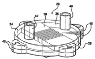
添付図面を参照すると、幾つかの図に亘り、同じ参照番号が対応する部品を示す。熱源22即ち電子部品からクーラント流体に熱を伝達するためのヒートシンク20を概略に示す。
Referring to the accompanying drawings, like reference numerals designate corresponding parts throughout the several views. A
ヒートシンク20は、蓋24及びベース26を含むハウジングによって形成されている。ベース26は平らな低温プレート(コールドプレート)であり、上面と、下面と、平行なマイクロチャンネル28を有する。これらのマイクロチャンネルは全て、同じ距離に亘って延びており、各マイクロチャンネルは、ベースの上面内に、ベース幅bwと、ベース高さbhとを有する。
The
マニホールド厚さmtを形成する上面及び下面を持つマニホールドプレート30が、下面をマイクロチャンネル28と重ねて配置される。マニホールドプレートは、両端部34間を延びる間隔が隔てられた縁部32を有する。蓋24は、ベース26と係合する周囲と、内肩部36とを有する。内肩部36は、マニホールドプレート30の端部34と係合して、マニホールドプレート30の上面と係合した凹所をなした表面38を周囲内に形成する。マニホールドプレート30の縁部32は、入口縁部32(図の右側)及び出口縁部32(図の左側)を形成する。これらの縁部の各々は、肩部36から間隔が隔てられており、入口縁部32と肩部36との間に入口プレナムを形成し、出口縁部32と肩部36との間に出口プレナムを形成する。流体を入口プレナムに流入するため、入口導管40が蓋24内に延びており、流体を出口プレナムから流出するため、出口導管42が蓋24内に延びている。
A
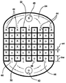
マニホールドプレート30は、入口縁部32内に延びる入口マニホールドチャンネル44と、出口縁部32内に延びる出口マニホールドチャンネル44とを有し、これらのマニホールドチャンネルの各々は、反対側の縁部32に対して間隔が隔てられた関係で終端する。入口マニホールドチャンネル44は、出口マニホールドチャンネル44と交互になっており、矩形のセルを形成する。図4に示すように、Xは、チャンネル44、46内への流れを示し、Oは、チャンネル44、46の外への流れを示す。この流れ構成のため、圧力降下が小さい。というのは、流れがマイクロチャンネル28に進入するときに収縮し、流れが逆転しマイクロチャンネル28から流出するときに膨張するためである。壁厚wtがマニホールドチャンネル44、46間に形成され、即ちマニホールドチャンネル44、46間に存在し、入口マニホールドチャンネル44は、出口縁部32から出口マニホールドチャンネル46と交互になっている。マニホールドチャンネル44、46は、マニホールド幅mwと、マニホールド厚さmtと等しいマニホールド高さmhとを備えている。
The
蓋24及びベースは、外形が円形であり、半径方向に延びる耳部48を備えている。これらの耳部48は、かみ合い係合するため、径方向に延びて設けられており、マニホールドを間に挟んだ状態で蓋24をベースにシールするためにボルトを受け入れるボルト穴を形成している。適当なガスケットを、かみ合う部品間に挟む。
The
理解されるように、マニホールドチャンネル44、46は、ベースのマイクロチャンネル28と交差して横断方向に延びている。これによって、クーラントは、ベースの外部と係合した熱源22から熱を運び去るため、図4及び図5に示すように、入口導管40から入口プレナムに、そして入口マニホールドチャンネル44に流入し、ここで流れをマイクロチャンネル28内に下方に強制的に押し込み、ここでクーラントは、出口マニホールドチャンネル46内に上方に方向を変え、出口導管42から出るために出口プレナムに入る。
最大の作動効率を得るため、マイクロチャンネル28のベース幅bwは、40μm乃至100μmの範囲に維持され、マイクロチャンネル28のベース内へのベース高さbhは、200μm乃至400μmの範囲に維持され、マニホールドチャンネル44、46のマニホールド厚さを通るマニホールド高さは、1000μm乃至3000μmの範囲に維持され、マニホールドチャンネル44、46のマニホールド幅mwは、350μm乃至1000μmの範囲に維持される。更に、マイクロチャンネル28の壁厚は、50μmである。理解を完全にするため、熱源22の発熱面積は、マイクロチャンネル28が設けられたベースの下面の有効熱伝達面積に対し、0.7乃至1の所定の比を有する。
As will be appreciated, the
In order to obtain the maximum operating efficiency, the base width bw of the
従って、本発明は、熱源22からクーラント流体に熱を伝達する方法を提供する。この熱伝達方法は、マニホールドの入口縁部32内に延びる入口マニホールドチャンネル44にクーラントを流入させ、ここで、流れを、マニホールドチャンネル44、46と交差して延びる平行であり且つ間隔が隔てられたマイクロチャンネル28内に下方(図4にXによって示す)に押し込み、クーラントの方向を上方に変え(図4にOによって示す)て、マニホールドの出口縁部32内に延び且つ入口マニホールドチャンネル44と交互になった、出口マニホールドチャンネル46に入れてここから出すことによって行われる。また、前記熱伝達方法は、マイクロチャンネル28のベース幅bwを40μm乃至100μmの範囲に維持し、マイクロチャンネル28のベース内へのベース高さbhを、200μm乃至400μmの範囲に維持し、マニホールドチャンネル44、46のマニホールド高さmhを1000μm乃至3000μmの範囲に維持し、マニホールドチャンネル44、46のマニホールド幅mwを350μm乃至1000μmの範囲に維持することによって、行われる。
Accordingly, the present invention provides a method for transferring heat from the
この方法は、更に、マニホールドチャンネル44、46及びマイクロチャンネル28を通るクーラントの流量を、毎分0.2ガロン(約0.757リットル)乃至0.3ガロン(約1.135リットル)に維持することを特徴とする。
This method further maintains the coolant flow rate through the
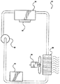
図6を参照し、液冷式システム50に組み込んだヒートシンク20の作動を概略に示す。ポンプ52等の作動流体移動装置が、通常は液体である冷却流体の流れを、余分な冷却流体を貯蔵する冷却流体貯蔵タンク54を通して移動する。ポンプ52は、冷却流体を熱交換器を通して移動させ、冷却流体から熱を放散する。熱交換器は、ファン56及びラジエータ58を備えている。ラジエータ58は、チューブを含み、これらのチューブ間に冷却フィンが設けられた周知の種類のラジエータであってもよく、チューブを通過する冷却流体と、ファン56によってラジエータ58を通して圧送された空気との間で熱交換を行う。
Referring to FIG. 6, the operation of the
明らかに、以上の教示に照らして、本発明の多くの変形及び変更を行うことができる。本発明は、具体的に説明した以外の態様で、特許請求の範囲の範囲内で実施できる。 Obviously, many modifications and variations of the present invention are possible in light of the above teachings. The invention may be practiced otherwise than as specifically described within the scope of the appended claims.
20 ヒートシンク
22 熱源
24 蓋
26 ベース
28 マイクロチャンネル
30 マニホールドプレート
32 縁部
34 端部
36 肩部
38 凹所をなした表面
40 入口導管
42 出口導管
44 入口マニホールドチャンネル
46 出口マニホールドチャンネル
48 耳部
50 液体冷却システム
52 ポンプ
54 貯蔵タンク
56 ファン
58 ラジエータ
bh ベース高さ
bw ベース幅
mh マニホールド高さ
mt マニホールド厚さ
mw マニホールド幅
wt 壁厚
20
Claims (6)
平らなベース(26)を有するハウジングを備えており、前記ベース(26)は、平行なマイクロチャンネル(28)が設けられた低温プレートを形成しており、前記マイクロチャンネルは、全て、同じ距離に亘って延びており、前記マイクロチャンネルの各々は、前記低温プレート内に、所定のベース幅(bw)と、所定のベース高さ(bh)とを有しており、
前記ヒートシンク(20)は、また、マニホールドプレート(30)を備え、前記マニホールドプレート(30)は、マニホールド厚さ(mt)を形成する上面及び下面を有しており、前記下面が前記マイクロチャンネル(28)と重なっており、前記マニホールドプレート(30)は、また、両端部(34)間を延びる、間隔が隔てられた縁部(32)を有しており、
前記ハウジングは、内部肩部(36)を有しており、該内部肩部(36)は、前記マニホールドプレート(30)の前記端部(34)と係合して、前記マニホールドプレート(30)の前記上面と係合する凹所をなした表面(38)を形成しており、
前記マニホールドプレート(30)の前記縁部(32)は、入口縁部(32)及び出口縁部(32)を形成し、入口縁部(32)及び出口縁部(32)は、各々、前記肩部(36)から各々間隔が隔てられて、前記入口縁部(32)と前記肩部(36)との間に入口プレナムを形成し、前記出口縁部(32)と前記肩部(36)との間に出口プレナムを形成しており、
前記マニホールドプレート(30)は、前記入口縁部(32)内に延びる入口マニホールドチャンネル(44)と、前記出口縁部(32)内に延びる出口マニホールドチャンネル(46)とを有し、これらのマニホールドチャンネルの各々は、反対側の縁部(32)に対して間隔が隔てられた関係で終端し、
前記入口マニホールドチャンネル(44)は、前記出口マニホールドチャンネル(46)と交互になって、下側のマイクロチャンネル(28)の壁厚(wt)を形成し、その結果、前記入口縁部(32)からの前記マニホールドチャンネル(44、46)は、前記出口縁部(32)からの前記マニホールドチャンネル(44、46)と交互になっており、前記マニホールドチャンネル(44、46)は、所定のマニホールド幅(mw)と、前記マニホールド厚さ(mt)と等しい所定のマニホールド高さ(mh)とを有しており、
前記マニホールドチャンネル(44、46)は、前記ベースの前記マイクロチャンネル(28)と交差方向に延びており、これによって、クーラントは、前記入口導管(40)から、前記入口プレナムに、そして前記入口マニホールドチャンネル(44)に流入し、該入口マニホールドチャンネル(44)で、流れが前記マイクロチャンネル(28)内に下方に押し込まれ、該マイクロチャンネル(28)で、クーラントは、前記出口マニホールドチャンネル(46)内に上方に方向を変え、前記出口導管(42)の外に出るため、前記出口プレナム内に出て、前記ベースの外部と係合した熱源(22)から熱を運び去り、
前記マイクロチャンネル(28)の前記ベース幅(bw)は、40μm乃至100μmの範囲にあり、
前記マイクロチャンネル(28)の前記ベース内への前記ベース高さ(bh)は、200μm乃至400μmの範囲にあり、
前記マニホールドチャンネル(44、46)の前記マニホールド厚さ(mt)を通る前記マニホールド高さ(mh)は、1000μm乃至3000μmの範囲にあり、
前記マニホールドチャンネル(44、46)の前記マニホールド幅(mw)は、350μm乃至1000μmの範囲にある、ヒートシンク。 A heat sink (20) for transferring heat from a heat source (22) to a coolant fluid,
A housing having a flat base (26), said base (26) forming a cold plate provided with parallel microchannels (28), all said microchannels being at the same distance; Each of the microchannels has a predetermined base width (bw) and a predetermined base height (bh) in the low temperature plate;
The heat sink (20) also includes a manifold plate (30), the manifold plate (30) having an upper surface and a lower surface that form a manifold thickness (mt), and the lower surface is the microchannel ( 28) and the manifold plate (30) also has spaced edges (32) extending between the ends (34);
The housing has an internal shoulder (36) that engages the end (34) of the manifold plate (30) to provide the manifold plate (30). Forming a recessed surface (38) that engages the top surface of
The edge (32) of the manifold plate (30) forms an inlet edge (32) and an outlet edge (32), and the inlet edge (32) and the outlet edge (32) are each Each spaced from the shoulder (36) forms an inlet plenum between the inlet edge (32) and the shoulder (36), and the outlet edge (32) and the shoulder (36). ) To form an exit plenum
The manifold plate (30) has an inlet manifold channel (44) extending into the inlet edge (32) and an outlet manifold channel (46) extending into the outlet edge (32). Each of the channels terminates in spaced relation to the opposite edge (32);
The inlet manifold channel (44) alternates with the outlet manifold channel (46) to form the wall thickness (wt) of the lower microchannel (28), so that the inlet edge (32) The manifold channels (44, 46) from the alternate with the manifold channels (44, 46) from the outlet edge (32), the manifold channels (44, 46) having a predetermined manifold width (Mw) and a predetermined manifold height (mh) equal to the manifold thickness (mt),
The manifold channel (44, 46) extends in a direction intersecting the microchannel (28) of the base so that coolant flows from the inlet conduit (40) to the inlet plenum and to the inlet manifold. Flows into the channel (44), where the inlet manifold channel (44) forces the flow down into the microchannel (28) where the coolant flows into the outlet manifold channel (46). Inwardly and out of the outlet conduit (42) to exit the outlet plenum and carry heat away from the heat source (22) engaged with the exterior of the base;
The base width (bw) of the microchannel (28) is in the range of 40 μm to 100 μm,
The base height (bh) into the base of the microchannel (28) is in the range of 200 μm to 400 μm;
The manifold height (mh) through the manifold thickness (mt) of the manifold channel (44, 46) is in the range of 1000 μm to 3000 μm;
The heat sink, wherein the manifold width (mw) of the manifold channel (44, 46) is in the range of 350 μm to 1000 μm.
前記熱源(22)は、前記ベースの前記下面の面積に対して0.7乃至1の所定の比を持つ面積を有する、ヒートシンク。 The heat sink according to claim 1.
The heat source (22) is a heat sink having an area having a predetermined ratio of 0.7 to 1 with respect to an area of the lower surface of the base.
前記壁厚(wt)は50μmである、ヒートシンク。 The heat sink according to claim 1.
The heat sink having a wall thickness (wt) of 50 μm.
蓋(24)及びベースを含むハウジングを備え、
前記ベースは、上面と、下面と、平行なマイクロチャンネル(28)とを持つ平らな低温プレートであり、前記マイクロチャンネルは全て、同じ距離に亘って延びており、前記マイクロチャンネルの各々は、前記ベースの前記上面内に所定のベース高さと、所定のベース幅(bw)とを有し、
また、前記ヒートシンク(20)は、
マニホールド厚さ(mt)を形成する上面及び下面を有し、前記下面が前記マイクロチャンネル(28)と重なり、間隔が隔てられた縁部が両端部(34)間を延びる、マニホールドプレート(30)を備え、
前記蓋(24)は、前記ベースと係合する周囲と、前記マニホールドプレート(30)の前記端部(34)と係合して、前記マニホールドプレート(30)の前記上面と係合する凹所をなした表面(38)を前記周囲内に形成する内部肩部(36)とを有し、
前記マニホールドプレート(30)の前記縁部(32)は、入口縁部(32)及び出口縁部(32)を形成しており、前記入口縁部(32)及び前記出口縁部(32)は、各々、前記肩部(36)から間隔が隔てられて、前記入口縁部(32)と前記肩部(36)との間に入口プレナムを形成し、前記出口縁部(32)と前記肩部(36)との間に出口プレナムを形成しており、
また、前記ヒートシンク(20)は、
前記入口プレナムに流体を流入するため、前記蓋(24)に設けられた入口導管(40)と、
前記出口プレナムから流体を流出するため、前記蓋(24)に設けられた出口導管(42)とを備えており、
前記マニホールドプレート(30)は、前記入口縁部(32)内に延びる入口マニホールドチャンネル(44)と、前記出口縁部(32)内に延びる出口マニホールドチャンネル(46)とを有し、これらのマニホールドチャンネルの各々は、反対側の縁部(32)に対して間隔が隔てられた関係で終端しており、
前記入口マニホールドチャンネル(44)は、前記出口マニホールドチャンネル(46)と交互になっており、その間に壁厚(wt)を形成し、その結果、前記入口縁部(32)からの前記マニホールドチャンネル(44、46)は、前記出口縁部(32)からの前記マニホールドチャンネル(44、46)と交互になっており、前記マニホールドチャンネル(44、46)は、所定のマニホールド幅(mw)と、前記マニホールド厚さ(mt)と等しい所定のマニホールド高さ(mh)とを有し、
前記蓋(24)及び前記ベースは、円形であり、かみ合い係合するため、及び前記蓋(24)を前記ベースに前記マニホールドをこれらの間に挟んだ状態でシールするためのボルト穴を形成するため、半径方向に延びる耳部(48)を有し、
前記ベースの前記下面と接触した所定の発熱面積を持つ熱源(22)を有し、
前記マニホールドチャンネル(44、46)は、前記ベースの前記マイクロチャンネル(28)と交差方向に延びており、これによって、クーラントは、前記入口導管(40)から、前記入口プレナムに、そして前記入口マニホールドチャンネル(44)に流入し、前記入口マニホールドチャンネル(44)で、流れを前記マイクロチャンネル(28)内に下方に押し込み、前記マイクロチャンネル(28)で、クーラントは、前記出口マニホールドチャンネル(46)内に上方に方向を変え、前記出口導管(42)を出るため、前記出口プレナム内に出て、前記ベースの外部と係合した熱源(22)から熱を運び去り、
前記マイクロチャンネル(28)の前記ベース幅(bw)は、40μm乃至100μmの範囲にあり、
前記マイクロチャンネル(28)の前記ベース内への前記ベース高さは、200μm乃至400μmの範囲にあり、
前記マニホールドチャンネル(44、46)の前記マニホールド厚さ(mt)を通る前記マニホールド高さ(mh)は、1000μm乃至3000μmの範囲にあり、
前記マニホールドチャンネル(44、46)の前記マニホールド幅(mw)は、350μm乃至1000μmの範囲にあり、
前記壁厚(wt)は50μmであり、
前記熱源(22)の前記発熱面積は、前記マイクロチャンネル(28)によって覆われた前記ベースの前記下面の有効熱伝達面積に対して0.7乃至1の所定の比を有する、ヒートシンク。 A heat sink (20) for transferring heat from a heat source (22) to a coolant fluid,
A housing including a lid (24) and a base;
The base is a flat cold plate having an upper surface, a lower surface, and parallel microchannels (28), all of the microchannels extending over the same distance, each of the microchannels being A predetermined base height and a predetermined base width (bw) in the upper surface of the base;
The heat sink (20)
A manifold plate (30) having an upper surface and a lower surface forming a manifold thickness (mt), the lower surface overlapping the microchannel (28), and spaced edges extending between the ends (34). With
The lid (24) engages with the base engaging the base and the end (34) of the manifold plate (30) to engage the upper surface of the manifold plate (30). An internal shoulder (36) forming a surface (38) in the perimeter,
The edge (32) of the manifold plate (30) forms an inlet edge (32) and an outlet edge (32), the inlet edge (32) and the outlet edge (32) Respectively, spaced from the shoulder (36) to form an inlet plenum between the inlet edge (32) and the shoulder (36), and the outlet edge (32) and the shoulder. An outlet plenum is formed between the part (36) and
The heat sink (20)
An inlet conduit (40) provided in the lid (24) for flowing fluid into the inlet plenum;
An outlet conduit (42) provided in the lid (24) for flowing fluid out of the outlet plenum;
The manifold plate (30) has an inlet manifold channel (44) extending into the inlet edge (32) and an outlet manifold channel (46) extending into the outlet edge (32). Each of the channels terminates in spaced relation to the opposite edge (32);
The inlet manifold channel (44) alternates with the outlet manifold channel (46) and forms a wall thickness (wt) therebetween, so that the manifold channel (32) from the inlet edge (32) 44, 46) alternate with the manifold channels (44, 46) from the outlet edge (32), the manifold channels (44, 46) having a predetermined manifold width (mw), and A predetermined manifold height (mh) equal to the manifold thickness (mt);
The lid (24) and the base are circular and form bolt holes for mating engagement and for sealing the lid (24) to the base with the manifold sandwiched therebetween. Thus having radially extending ears (48),
A heat source (22) having a predetermined heat generation area in contact with the lower surface of the base;
The manifold channel (44, 46) extends in a direction crossing the microchannel (28) of the base, so that coolant flows from the inlet conduit (40) to the inlet plenum and to the inlet manifold. Into the channel (44), and at the inlet manifold channel (44), the flow is pushed down into the microchannel (28), where the coolant flows into the outlet manifold channel (46). To exit the outlet conduit (42), exit into the outlet plenum and carry away heat from a heat source (22) engaged with the exterior of the base;
The base width (bw) of the microchannel (28) is in the range of 40 μm to 100 μm,
The base height into the base of the microchannel (28) is in the range of 200 μm to 400 μm;
The manifold height (mh) through the manifold thickness (mt) of the manifold channel (44, 46) is in the range of 1000 μm to 3000 μm;
The manifold width (mw) of the manifold channel (44, 46) is in the range of 350 μm to 1000 μm,
The wall thickness (wt) is 50 μm,
A heat sink, wherein the heat generation area of the heat source (22) has a predetermined ratio of 0.7 to 1 with respect to an effective heat transfer area of the lower surface of the base covered by the microchannel (28).
マニホールドの入口縁部(32)内に延びる入口マニホールドチャンネル(44)にクーラントを流入し、前記入口マニホールドチャンネル(44)で、前記クーラントの流れを、前記マニホールドチャンネル(44、46)と交差して延びる平行であり且つ間隔が隔てられたマイクロチャンネル(28)に下方に押し込み、前記マニホールドの出口縁部(32)内に延び且つ前記入口マニホールドチャンネル(44)と交互になった出口マニホールドチャンネル(46)内に、クーラントの向きを上方に変えてここから出す、工程と、
前記マイクロチャンネル(28)のベース幅(bw)を40μm乃至100μmの範囲に維持する工程と、
前記マイクロチャンネル(28)のベース高さ(bh)を200μm乃至400μmの範囲に維持する工程と、
マニホールドチャンネル(44、46)を通るマニホールド高さ(mh)を1000μm乃至3000μmの範囲に維持する工程と、
マニホールドチャンネル(44、46)のマニホールド幅(mw)を350μm乃至1000μmの範囲に維持する工程とを含む、方法。 A method of transferring heat from a heat source (22) to a coolant fluid comprising:
Coolant flows into an inlet manifold channel (44) extending into the inlet edge (32) of the manifold, and at the inlet manifold channel (44), the coolant flow intersects the manifold channel (44, 46). Outlet manifold channels (46) that push down into parallel and spaced apart microchannels (28) that extend into the outlet edge (32) of the manifold and alternate with the inlet manifold channel (44). ), The direction of the coolant is changed upward, and the process starts from here,
Maintaining the base width (bw) of the microchannel (28) in the range of 40 μm to 100 μm;
Maintaining the base height (bh) of the microchannel (28) in the range of 200 μm to 400 μm;
Maintaining the manifold height (mh) through the manifold channels (44, 46) in the range of 1000 μm to 3000 μm;
Maintaining the manifold width (mw) of the manifold channels (44, 46) in the range of 350 μm to 1000 μm.
前記マニホールドチャンネル(44、46)及びマイクロチャンネル(28)を通るクーラントの流量を、毎分0.2ガロン乃至0.3ガロンに維持する、方法。 The method of claim 5, wherein
A method wherein the coolant flow rate through the manifold channels (44, 46) and microchannels (28) is maintained between 0.2 and 0.3 gallons per minute.
Applications Claiming Priority (1)
| Application Number | Priority Date | Filing Date | Title |
|---|---|---|---|
| US11/333,655 US7331378B2 (en) | 2006-01-17 | 2006-01-17 | Microchannel heat sink |
Publications (1)
| Publication Number | Publication Date |
|---|---|
| JP2007227902A true JP2007227902A (en) | 2007-09-06 |
Family
ID=37950212
Family Applications (1)
| Application Number | Title | Priority Date | Filing Date |
|---|---|---|---|
| JP2007006924A Pending JP2007227902A (en) | 2006-01-17 | 2007-01-16 | Micro channel heatsink |
Country Status (4)
| Country | Link |
|---|---|
| US (1) | US7331378B2 (en) |
| EP (1) | EP1808892A3 (en) |
| JP (1) | JP2007227902A (en) |
| CN (1) | CN100539819C (en) |
Cited By (18)
| Publication number | Priority date | Publication date | Assignee | Title |
|---|---|---|---|---|
| JP2010147478A (en) * | 2008-12-22 | 2010-07-01 | General Electric Co <Ge> | Low cost manufacturing of micro-channel heat sink |
| JP2012015509A (en) * | 2010-06-29 | 2012-01-19 | General Electric Co <Ge> | Heat sinks with c-shaped manifolds and millichannel cooling |
| JP3179086U (en) * | 2011-07-27 | 2012-10-18 | クールイット システムズ インク | Fluid heat exchange system |
| JP2013016794A (en) * | 2011-06-24 | 2013-01-24 | General Electric Co <Ge> | Cooling device for power module, and related method thereof |
| US8746330B2 (en) | 2007-08-09 | 2014-06-10 | Coolit Systems Inc. | Fluid heat exchanger configured to provide a split flow |
| US9057567B2 (en) | 2007-08-09 | 2015-06-16 | Coolit Systems, Inc. | Fluid heat exchange systems |
| JP2015173301A (en) * | 2009-03-13 | 2015-10-01 | ゼネラル・エレクトリック・カンパニイ | Double side cooled power module with power overlay |
| US9496200B2 (en) | 2011-07-27 | 2016-11-15 | Coolit Systems, Inc. | Modular heat-transfer systems |
| US9943014B2 (en) | 2013-03-15 | 2018-04-10 | Coolit Systems, Inc. | Manifolded heat exchangers and related systems |
| US10365667B2 (en) | 2011-08-11 | 2019-07-30 | Coolit Systems, Inc. | Flow-path controllers and related systems |
| US10364809B2 (en) | 2013-03-15 | 2019-07-30 | Coolit Systems, Inc. | Sensors, multiplexed communication techniques, and related systems |
| US10415597B2 (en) | 2014-10-27 | 2019-09-17 | Coolit Systems, Inc. | Fluid heat exchange systems |
| WO2020241314A1 (en) * | 2019-05-28 | 2020-12-03 | 三井化学株式会社 | Cooling device and method for manufacturing cooling device |
| US11395443B2 (en) | 2020-05-11 | 2022-07-19 | Coolit Systems, Inc. | Liquid pumping units, and related systems and methods |
| US11452243B2 (en) | 2017-10-12 | 2022-09-20 | Coolit Systems, Inc. | Cooling system, controllers and methods |
| US11473860B2 (en) | 2019-04-25 | 2022-10-18 | Coolit Systems, Inc. | Cooling module with leak detector and related systems |
| US11662037B2 (en) | 2019-01-18 | 2023-05-30 | Coolit Systems, Inc. | Fluid flow control valve for fluid flow systems, and methods |
| US11725886B2 (en) | 2021-05-20 | 2023-08-15 | Coolit Systems, Inc. | Modular fluid heat exchange systems |
Families Citing this family (35)
| Publication number | Priority date | Publication date | Assignee | Title |
|---|---|---|---|---|
| US7511957B2 (en) * | 2006-05-25 | 2009-03-31 | International Business Machines Corporation | Methods for fabricating a cooled electronic module employing a thermally conductive return manifold structure sealed to the periphery of a surface to be cooled |
| US20080229580A1 (en) * | 2007-03-23 | 2008-09-25 | Russell Charles Anderson | Method of manufacturing a brazed micro-channel cold plate heat exchanger assembly |
| JP4922903B2 (en) * | 2007-11-27 | 2012-04-25 | 株式会社日立製作所 | Cooling device for electronic equipment |
| US20090154091A1 (en) * | 2007-12-17 | 2009-06-18 | Yatskov Alexander I | Cooling systems and heat exchangers for cooling computer components |
| US8170724B2 (en) | 2008-02-11 | 2012-05-01 | Cray Inc. | Systems and associated methods for controllably cooling computer components |
| US7775062B2 (en) * | 2008-09-15 | 2010-08-17 | Mike Blomquist | Modular cooling system |
| US8120915B2 (en) * | 2008-08-18 | 2012-02-21 | General Electric Company | Integral heat sink with spiral manifolds |
| US7817422B2 (en) * | 2008-08-18 | 2010-10-19 | General Electric Company | Heat sink and cooling and packaging stack for press-packages |
| EP2344829A4 (en) * | 2008-09-30 | 2013-07-31 | Baltimore Aircoil Co Inc | Cooling system with microchannel heat exchanger |
| US20100296249A1 (en) * | 2009-05-19 | 2010-11-25 | Beijing AVC Technology Research Center Co., Ltd. | Micro passage cold plate device for a liquid cooling radiator |
| US20110186267A1 (en) * | 2010-02-01 | 2011-08-04 | Suna Display Co. | Heat transfer device with anisotropic thermal conducting micro structures |
| JP4983959B2 (en) * | 2010-04-27 | 2012-07-25 | 株式会社デンソー | Switching power supply |
| US8897010B2 (en) * | 2011-08-22 | 2014-11-25 | General Electric Company | High performance liquid cooled heatsink for IGBT modules |
| US11092977B1 (en) | 2017-10-30 | 2021-08-17 | Zane Coleman | Fluid transfer component comprising a film with fluid channels |
| CN103188912A (en) * | 2011-12-27 | 2013-07-03 | 刘源 | Lotus-type regular porous metal microchannel heat sink using liquid metal working medium |
| US9353999B2 (en) | 2012-07-30 | 2016-05-31 | Toyota Motor Engineering & Manufacturing North America, Inc. | Cooling apparatuses and electronics modules having branching microchannels |
| US8937810B2 (en) * | 2012-09-14 | 2015-01-20 | International Business Machines Corporation | Electronic assembly with detachable coolant manifold and coolant-cooled electronic module |
| US9477275B2 (en) * | 2013-01-18 | 2016-10-25 | Intel Corporation | Thermal management solution for circuit products |
| JP6394267B2 (en) * | 2014-10-15 | 2018-09-26 | 富士通株式会社 | Cooling device and electronic equipment |
| US9655281B2 (en) | 2015-06-26 | 2017-05-16 | Seagate Technology Llc | Modular cooling system |
| US9953899B2 (en) | 2015-09-30 | 2018-04-24 | Microfabrica Inc. | Micro heat transfer arrays, micro cold plates, and thermal management systems for cooling semiconductor devices, and methods for using and making such arrays, plates, and systems |
| KR101822304B1 (en) * | 2016-10-24 | 2018-01-25 | 현대자동차주식회사 | Apparatus for cooling battery |
| WO2018142310A1 (en) * | 2017-02-03 | 2018-08-09 | Asetek Danmark A/S | Liquid cooling systems for heat generating devices |
| CN109890171A (en) * | 2017-12-06 | 2019-06-14 | 泽鸿(广州)电子科技有限公司 | Liquid cooling radiation module |
| CN109346446B (en) * | 2018-09-14 | 2020-04-24 | 大连理工大学 | Bonding packaging method suitable for large-size and high-density structure metal microchannel radiator |
| US11804418B2 (en) * | 2019-01-11 | 2023-10-31 | Intel Corporation | Direct liquid micro jet (DLMJ) structures for addressing thermal performance at limited flow rate conditions |
| US10905028B2 (en) * | 2019-05-07 | 2021-01-26 | International Business Machines Corporation | Structure for eliminating the impact of cold plate fouling |
| US11507153B2 (en) | 2019-06-27 | 2022-11-22 | Hypertechnologie Ciara Inc. | Microgap system for cooling electronics with direct contact |
| US11101509B2 (en) * | 2019-10-02 | 2021-08-24 | GM Global Technology Operations LLC | Battery cooling plate with distributed coolant flow |
| JP7352830B2 (en) * | 2019-12-04 | 2023-09-29 | 株式会社オートネットワーク技術研究所 | circuit construct |
| CN111244050B (en) * | 2020-03-27 | 2022-03-25 | 上海先方半导体有限公司 | Chip-level integrated microfluid heat dissipation module and preparation method thereof |
| CN111900143A (en) * | 2020-07-31 | 2020-11-06 | 上海交通大学 | Manifold type high depth-width ratio micro-channel heat exchanger |
| CN114280443A (en) * | 2021-11-03 | 2022-04-05 | 浙江大学杭州国际科创中心 | Power chip manifold type micro-channel heat exchanger testing device |
| CN114136129B (en) * | 2021-12-20 | 2023-02-03 | 山东大学 | Manifold micro-column array flat plate heat exchanger |
| CN116916632B (en) * | 2023-09-08 | 2023-12-01 | 北京航空航天大学 | Microchannel cold plate with staggered shearing flow channels and application method thereof |
Citations (9)
| Publication number | Priority date | Publication date | Assignee | Title |
|---|---|---|---|---|
| JPS60126854A (en) * | 1983-12-14 | 1985-07-06 | Hitachi Ltd | Cooling device for semiconductor element |
| JPH06318654A (en) * | 1990-07-10 | 1994-11-15 | Univ Iowa Res Found | High power semiconductor device with integral heat sink and forming method therefor |
| JPH07249721A (en) * | 1994-03-10 | 1995-09-26 | Fuji Electric Co Ltd | Cooling body for power semiconductor element |
| JP2003507893A (en) * | 1999-08-16 | 2003-02-25 | ザクリトエ・アクツィオネルノエ・オブシェストヴォ・《エネルゴマシュテクニカ》 | Heat sink for high power semiconductor laser |
| JP2003212676A (en) * | 2001-09-21 | 2003-07-30 | Alstom | Method of improving adhesion properties of non-oxide ceramic substrate before gluing it |
| JP2004128457A (en) * | 2002-10-02 | 2004-04-22 | Atotech Deutsche Gmbh | Micro-structure cooler and its usage |
| WO2005001674A1 (en) * | 2003-06-27 | 2005-01-06 | Nec Corporation | Cooler for electronic equipment |
| JP2007531991A (en) * | 2004-03-31 | 2007-11-08 | ハイドロクール ピーティーワイ リミテッド | Heat exchanger |
| JP2009518615A (en) * | 2005-12-09 | 2009-05-07 | フォルシュングスツェントルム カールスルーエ ゲゼルシャフト ミット ベシュレンクテル ハフツング | Use of a micro heat transfer device as a fluid cooler for micro heat transfer and electronic devices |
Family Cites Families (13)
| Publication number | Priority date | Publication date | Assignee | Title |
|---|---|---|---|---|
| US4758926A (en) * | 1986-03-31 | 1988-07-19 | Microelectronics And Computer Technology Corporation | Fluid-cooled integrated circuit package |
| JPH07114250B2 (en) * | 1990-04-27 | 1995-12-06 | インターナショナル・ビジネス・マシーンズ・コーポレイション | Heat transfer system |
| US5453641A (en) * | 1992-12-16 | 1995-09-26 | Sdl, Inc. | Waste heat removal system |
| US6988534B2 (en) * | 2002-11-01 | 2006-01-24 | Cooligy, Inc. | Method and apparatus for flexible fluid delivery for cooling desired hot spots in a heat producing device |
| JP2006522463A (en) * | 2002-11-01 | 2006-09-28 | クーリギー インコーポレイテッド | Optimal spreader system, apparatus and method for micro heat exchange cooled by fluid |
| US6986382B2 (en) * | 2002-11-01 | 2006-01-17 | Cooligy Inc. | Interwoven manifolds for pressure drop reduction in microchannel heat exchangers |
| US20050211417A1 (en) * | 2002-11-01 | 2005-09-29 | Cooligy,Inc. | Interwoven manifolds for pressure drop reduction in microchannel heat exchangers |
| DE10393618T5 (en) * | 2002-11-01 | 2005-11-17 | Cooligy, Inc., Mountain View | Method and apparatus for achieving temperature uniformity and for cooling overheat points in a heat generating device |
| US7017654B2 (en) * | 2003-03-17 | 2006-03-28 | Cooligy, Inc. | Apparatus and method of forming channels in a heat-exchanging device |
| US7032651B2 (en) * | 2003-06-23 | 2006-04-25 | Raytheon Company | Heat exchanger |
| US7139172B2 (en) * | 2004-07-01 | 2006-11-21 | International Business Machines Corporation | Apparatus and methods for microchannel cooling of semiconductor integrated circuit packages |
| US20060096738A1 (en) * | 2004-11-05 | 2006-05-11 | Aavid Thermalloy, Llc | Liquid cold plate heat exchanger |
| US7353859B2 (en) * | 2004-11-24 | 2008-04-08 | General Electric Company | Heat sink with microchannel cooling for power devices |
-
2006
- 2006-01-17 US US11/333,655 patent/US7331378B2/en active Active
-
2007
- 2007-01-09 EP EP07075014A patent/EP1808892A3/en not_active Withdrawn
- 2007-01-16 JP JP2007006924A patent/JP2007227902A/en active Pending
- 2007-01-17 CN CNB2007100083150A patent/CN100539819C/en not_active Expired - Fee Related
Patent Citations (9)
| Publication number | Priority date | Publication date | Assignee | Title |
|---|---|---|---|---|
| JPS60126854A (en) * | 1983-12-14 | 1985-07-06 | Hitachi Ltd | Cooling device for semiconductor element |
| JPH06318654A (en) * | 1990-07-10 | 1994-11-15 | Univ Iowa Res Found | High power semiconductor device with integral heat sink and forming method therefor |
| JPH07249721A (en) * | 1994-03-10 | 1995-09-26 | Fuji Electric Co Ltd | Cooling body for power semiconductor element |
| JP2003507893A (en) * | 1999-08-16 | 2003-02-25 | ザクリトエ・アクツィオネルノエ・オブシェストヴォ・《エネルゴマシュテクニカ》 | Heat sink for high power semiconductor laser |
| JP2003212676A (en) * | 2001-09-21 | 2003-07-30 | Alstom | Method of improving adhesion properties of non-oxide ceramic substrate before gluing it |
| JP2004128457A (en) * | 2002-10-02 | 2004-04-22 | Atotech Deutsche Gmbh | Micro-structure cooler and its usage |
| WO2005001674A1 (en) * | 2003-06-27 | 2005-01-06 | Nec Corporation | Cooler for electronic equipment |
| JP2007531991A (en) * | 2004-03-31 | 2007-11-08 | ハイドロクール ピーティーワイ リミテッド | Heat exchanger |
| JP2009518615A (en) * | 2005-12-09 | 2009-05-07 | フォルシュングスツェントルム カールスルーエ ゲゼルシャフト ミット ベシュレンクテル ハフツング | Use of a micro heat transfer device as a fluid cooler for micro heat transfer and electronic devices |
Cited By (29)
| Publication number | Priority date | Publication date | Assignee | Title |
|---|---|---|---|---|
| US9603284B2 (en) | 2007-08-09 | 2017-03-21 | Coolit Systems, Inc. | Fluid heat exchanger configured to provide a split flow |
| US8746330B2 (en) | 2007-08-09 | 2014-06-10 | Coolit Systems Inc. | Fluid heat exchanger configured to provide a split flow |
| US9057567B2 (en) | 2007-08-09 | 2015-06-16 | Coolit Systems, Inc. | Fluid heat exchange systems |
| US9453691B2 (en) | 2007-08-09 | 2016-09-27 | Coolit Systems, Inc. | Fluid heat exchange systems |
| US10274266B2 (en) | 2007-08-09 | 2019-04-30 | CoolIT Systems, Inc | Fluid heat exchange sytems |
| JP2010147478A (en) * | 2008-12-22 | 2010-07-01 | General Electric Co <Ge> | Low cost manufacturing of micro-channel heat sink |
| JP2015173301A (en) * | 2009-03-13 | 2015-10-01 | ゼネラル・エレクトリック・カンパニイ | Double side cooled power module with power overlay |
| JP2012015509A (en) * | 2010-06-29 | 2012-01-19 | General Electric Co <Ge> | Heat sinks with c-shaped manifolds and millichannel cooling |
| JP2013016794A (en) * | 2011-06-24 | 2013-01-24 | General Electric Co <Ge> | Cooling device for power module, and related method thereof |
| US9496200B2 (en) | 2011-07-27 | 2016-11-15 | Coolit Systems, Inc. | Modular heat-transfer systems |
| JP3179086U (en) * | 2011-07-27 | 2012-10-18 | クールイット システムズ インク | Fluid heat exchange system |
| US10820450B2 (en) | 2011-07-27 | 2020-10-27 | Coolit Systems, Inc. | Modular heat-transfer systems |
| US10365667B2 (en) | 2011-08-11 | 2019-07-30 | Coolit Systems, Inc. | Flow-path controllers and related systems |
| US11714432B2 (en) | 2011-08-11 | 2023-08-01 | Coolit Systems, Inc. | Flow-path controllers and related systems |
| US9943014B2 (en) | 2013-03-15 | 2018-04-10 | Coolit Systems, Inc. | Manifolded heat exchangers and related systems |
| US11661936B2 (en) | 2013-03-15 | 2023-05-30 | Coolit Systems, Inc. | Sensors, multiplexed communication techniques, and related systems |
| US10364809B2 (en) | 2013-03-15 | 2019-07-30 | Coolit Systems, Inc. | Sensors, multiplexed communication techniques, and related systems |
| US10415597B2 (en) | 2014-10-27 | 2019-09-17 | Coolit Systems, Inc. | Fluid heat exchange systems |
| US11452243B2 (en) | 2017-10-12 | 2022-09-20 | Coolit Systems, Inc. | Cooling system, controllers and methods |
| US11662037B2 (en) | 2019-01-18 | 2023-05-30 | Coolit Systems, Inc. | Fluid flow control valve for fluid flow systems, and methods |
| US11473860B2 (en) | 2019-04-25 | 2022-10-18 | Coolit Systems, Inc. | Cooling module with leak detector and related systems |
| US11725890B2 (en) | 2019-04-25 | 2023-08-15 | Coolit Systems, Inc. | Cooling module with leak detector and related systems |
| JPWO2020241314A1 (en) * | 2019-05-28 | 2021-11-04 | 三井化学株式会社 | Cooling device and manufacturing method of cooling device |
| JP7249408B2 (en) | 2019-05-28 | 2023-03-30 | 三井化学株式会社 | Cooling device and cooling device manufacturing method |
| KR20210101277A (en) * | 2019-05-28 | 2021-08-18 | 미쯔이가가꾸가부시끼가이샤 | Cooling device and manufacturing method of cooling device |
| WO2020241314A1 (en) * | 2019-05-28 | 2020-12-03 | 三井化学株式会社 | Cooling device and method for manufacturing cooling device |
| KR102570354B1 (en) * | 2019-05-28 | 2023-08-25 | 미쯔이가가꾸가부시끼가이샤 | Cooling device and manufacturing method of cooling device |
| US11395443B2 (en) | 2020-05-11 | 2022-07-19 | Coolit Systems, Inc. | Liquid pumping units, and related systems and methods |
| US11725886B2 (en) | 2021-05-20 | 2023-08-15 | Coolit Systems, Inc. | Modular fluid heat exchange systems |
Also Published As
| Publication number | Publication date |
|---|---|
| EP1808892A2 (en) | 2007-07-18 |
| CN101005753A (en) | 2007-07-25 |
| US7331378B2 (en) | 2008-02-19 |
| EP1808892A3 (en) | 2010-05-19 |
| CN100539819C (en) | 2009-09-09 |
| US20070163750A1 (en) | 2007-07-19 |
Similar Documents
| Publication | Publication Date | Title |
|---|---|---|
| JP2007227902A (en) | Micro channel heatsink | |
| US7537047B2 (en) | Liquid-cooling heat sink | |
| JP5135225B2 (en) | Use of a micro heat transfer device as a fluid cooler for micro heat transfer and electronic devices | |
| US7584781B2 (en) | Liquid-cooling device | |
| US20050133212A1 (en) | Forced fluid heat sink | |
| US20070025082A1 (en) | Microchannel heat sink | |
| JP2006294678A (en) | Radiator and cooling device having the same | |
| US10004159B2 (en) | Water-cooling radiator unit and device thereof | |
| US8746326B2 (en) | Liquid heat-dissipating module | |
| JP2013083436A (en) | Internal heat exchanger with external manifold | |
| KR102296543B1 (en) | Liquid-cooled heat sink | |
| CN110567301A (en) | Heat dissipation plate and manufacturing method thereof | |
| JP4619387B2 (en) | Semiconductor device cooling device | |
| JP2009099740A (en) | Cooling device for housing | |
| US8899307B2 (en) | Cooling device | |
| JP4041437B2 (en) | Semiconductor device cooling device | |
| JP2009068834A (en) | Condenser assembly | |
| JP4682775B2 (en) | Microchannel structure, heat exchange system, and electronic device | |
| US20120103575A1 (en) | Cooling device | |
| KR20080076222A (en) | Laminated heat exchanger and fabricating method thereof | |
| JP5601257B2 (en) | Manufacturing method of plate type cooler | |
| JP2015159254A (en) | Cooling device and manufacturing method of the same | |
| TWM536759U (en) | Water discharge unit and its device | |
| CN107809877B (en) | Cooling water drainage device and water cooling module thereof | |
| JP2005123260A (en) | Water-cooled heatsink |
Legal Events
| Date | Code | Title | Description |
|---|---|---|---|
| A977 | Report on retrieval |
Free format text: JAPANESE INTERMEDIATE CODE: A971007 Effective date: 20100416 |
|
| A131 | Notification of reasons for refusal |
Free format text: JAPANESE INTERMEDIATE CODE: A131 Effective date: 20100421 |
|
| A02 | Decision of refusal |
Free format text: JAPANESE INTERMEDIATE CODE: A02 Effective date: 20101001 |