JP2007149357A - Conductive porous body for fuel cell, fuel cell equipped with it, and their manufacturing method - Google Patents
Conductive porous body for fuel cell, fuel cell equipped with it, and their manufacturing method Download PDFInfo
- Publication number
- JP2007149357A JP2007149357A JP2005338181A JP2005338181A JP2007149357A JP 2007149357 A JP2007149357 A JP 2007149357A JP 2005338181 A JP2005338181 A JP 2005338181A JP 2005338181 A JP2005338181 A JP 2005338181A JP 2007149357 A JP2007149357 A JP 2007149357A
- Authority
- JP
- Japan
- Prior art keywords
- layer
- porous body
- fuel cell
- conductive
- cell according
- Prior art date
- Legal status (The legal status is an assumption and is not a legal conclusion. Google has not performed a legal analysis and makes no representation as to the accuracy of the status listed.)
- Granted
Links
Images


Classifications
-
- H—ELECTRICITY
- H01—ELECTRIC ELEMENTS
- H01M—PROCESSES OR MEANS, e.g. BATTERIES, FOR THE DIRECT CONVERSION OF CHEMICAL ENERGY INTO ELECTRICAL ENERGY
- H01M8/00—Fuel cells; Manufacture thereof
- H01M8/02—Details
-
- H—ELECTRICITY
- H01—ELECTRIC ELEMENTS
- H01M—PROCESSES OR MEANS, e.g. BATTERIES, FOR THE DIRECT CONVERSION OF CHEMICAL ENERGY INTO ELECTRICAL ENERGY
- H01M8/00—Fuel cells; Manufacture thereof
- H01M8/02—Details
- H01M8/0202—Collectors; Separators, e.g. bipolar separators; Interconnectors
- H01M8/023—Porous and characterised by the material
- H01M8/0232—Metals or alloys
-
- H—ELECTRICITY
- H01—ELECTRIC ELEMENTS
- H01M—PROCESSES OR MEANS, e.g. BATTERIES, FOR THE DIRECT CONVERSION OF CHEMICAL ENERGY INTO ELECTRICAL ENERGY
- H01M8/00—Fuel cells; Manufacture thereof
- H01M8/02—Details
- H01M8/0202—Collectors; Separators, e.g. bipolar separators; Interconnectors
- H01M8/023—Porous and characterised by the material
- H01M8/0241—Composites
- H01M8/0245—Composites in the form of layered or coated products
-
- H—ELECTRICITY
- H01—ELECTRIC ELEMENTS
- H01M—PROCESSES OR MEANS, e.g. BATTERIES, FOR THE DIRECT CONVERSION OF CHEMICAL ENERGY INTO ELECTRICAL ENERGY
- H01M8/00—Fuel cells; Manufacture thereof
- H01M8/02—Details
- H01M8/0202—Collectors; Separators, e.g. bipolar separators; Interconnectors
- H01M8/0247—Collectors; Separators, e.g. bipolar separators; Interconnectors characterised by the form
- H01M8/0254—Collectors; Separators, e.g. bipolar separators; Interconnectors characterised by the form corrugated or undulated
-
- H—ELECTRICITY
- H01—ELECTRIC ELEMENTS
- H01M—PROCESSES OR MEANS, e.g. BATTERIES, FOR THE DIRECT CONVERSION OF CHEMICAL ENERGY INTO ELECTRICAL ENERGY
- H01M8/00—Fuel cells; Manufacture thereof
- H01M8/04—Auxiliary arrangements, e.g. for control of pressure or for circulation of fluids
-
- Y—GENERAL TAGGING OF NEW TECHNOLOGICAL DEVELOPMENTS; GENERAL TAGGING OF CROSS-SECTIONAL TECHNOLOGIES SPANNING OVER SEVERAL SECTIONS OF THE IPC; TECHNICAL SUBJECTS COVERED BY FORMER USPC CROSS-REFERENCE ART COLLECTIONS [XRACs] AND DIGESTS
- Y02—TECHNOLOGIES OR APPLICATIONS FOR MITIGATION OR ADAPTATION AGAINST CLIMATE CHANGE
- Y02E—REDUCTION OF GREENHOUSE GAS [GHG] EMISSIONS, RELATED TO ENERGY GENERATION, TRANSMISSION OR DISTRIBUTION
- Y02E60/00—Enabling technologies; Technologies with a potential or indirect contribution to GHG emissions mitigation
- Y02E60/30—Hydrogen technology
- Y02E60/50—Fuel cells
-
- Y—GENERAL TAGGING OF NEW TECHNOLOGICAL DEVELOPMENTS; GENERAL TAGGING OF CROSS-SECTIONAL TECHNOLOGIES SPANNING OVER SEVERAL SECTIONS OF THE IPC; TECHNICAL SUBJECTS COVERED BY FORMER USPC CROSS-REFERENCE ART COLLECTIONS [XRACs] AND DIGESTS
- Y02—TECHNOLOGIES OR APPLICATIONS FOR MITIGATION OR ADAPTATION AGAINST CLIMATE CHANGE
- Y02P—CLIMATE CHANGE MITIGATION TECHNOLOGIES IN THE PRODUCTION OR PROCESSING OF GOODS
- Y02P70/00—Climate change mitigation technologies in the production process for final industrial or consumer products
- Y02P70/50—Manufacturing or production processes characterised by the final manufactured product
Landscapes
- Chemical & Material Sciences (AREA)
- Life Sciences & Earth Sciences (AREA)
- Engineering & Computer Science (AREA)
- Manufacturing & Machinery (AREA)
- Sustainable Development (AREA)
- Sustainable Energy (AREA)
- Chemical Kinetics & Catalysis (AREA)
- Electrochemistry (AREA)
- General Chemical & Material Sciences (AREA)
- Composite Materials (AREA)
- Fuel Cell (AREA)
- Inert Electrodes (AREA)
Abstract
Description
本発明は、燃料電池用導電性多孔体、それを備えた燃料電池およびそれらの製造方法に関する。 The present invention relates to a conductive porous body for a fuel cell, a fuel cell including the same, and a method for manufacturing the same.
燃料電池は、一般的には水素及び酸素を燃料として電気エネルギーを得る装置である。この燃料電池は、環境面において優れかつ高いエネルギー効率が実現できることから、今後のエネルギー供給システムとして広く開発が進められてきている。特に、固体高分子型燃料電池は、各種の燃料電池の中でも比較的低温で作動することから、良好な起動性を有する。そのため、多方面における実用化のために盛んに研究がなされている。 A fuel cell is a device that generally obtains electric energy using hydrogen and oxygen as fuel. This fuel cell is environmentally superior and can realize high energy efficiency, and therefore has been widely developed as a future energy supply system. In particular, since the polymer electrolyte fuel cell operates at a relatively low temperature among various types of fuel cells, it has a good startability. For this reason, research has been actively conducted for practical application in various fields.
固体高分子型燃料電池は、固体高分子電解質膜の両面に触媒層を接合して構成された膜電極接合体の両面に、集電体が密に接するように配置されている。この集電体には多孔質の導電体が用いられることが多い。燃料電池の発電効率を向上させるために、この集電体と膜電極接合体との接触抵抗を低減させる必要がある。そこで、集電体として用いるチタン焼結体の表面を研磨および切削する技術が開示されている(例えば、特許文献1参照)。この技術によれば、集電体と膜電極接合体との接触面積比率を向上させることができる。 The polymer electrolyte fuel cell is arranged so that the current collector is in close contact with both surfaces of a membrane electrode assembly formed by bonding a catalyst layer to both surfaces of a solid polymer electrolyte membrane. For this current collector, a porous conductor is often used. In order to improve the power generation efficiency of the fuel cell, it is necessary to reduce the contact resistance between the current collector and the membrane electrode assembly. Therefore, a technique for polishing and cutting the surface of a titanium sintered body used as a current collector is disclosed (for example, see Patent Document 1). According to this technique, the contact area ratio between the current collector and the membrane electrode assembly can be improved.
しかしながら、特許文献1の技術では、研磨および切削の際に、集電体の内部性状が変化してしまうおそれがある。この場合、集電体の品質管理を行うことが困難になる。 However, in the technique of Patent Document 1, the internal properties of the current collector may change during polishing and cutting. In this case, it becomes difficult to perform quality control of the current collector.
本発明は、内部性状を変化させることなく膜電極接合体との接触抵抗を低減させることができる燃料電池用導電性多孔体、それを備えた燃料電池およびそれらの製造方法を提供することを目的とする。 An object of the present invention is to provide a conductive porous body for a fuel cell that can reduce the contact resistance with the membrane electrode assembly without changing the internal properties, a fuel cell including the same, and a method for manufacturing the same. And
本発明に係る燃料電池用導電性多孔体は、金属多孔体と、金属多孔体の一面側に配置されガス透過性を有する導電性層とを備え、金属多孔体の一面側の少なくとも一部は導電性層の他面に埋め込まれ、導電性層の一面側の平面度は金属多孔体の一面側の平面度よりも高いことを特徴とするものである。 The conductive porous body for a fuel cell according to the present invention includes a metal porous body and a conductive layer disposed on one surface side of the metal porous body and having gas permeability, and at least a part of one surface side of the metal porous body is It is embedded in the other surface of the conductive layer, and the flatness on the one surface side of the conductive layer is higher than the flatness on the one surface side of the metal porous body.
本発明に係る燃料電池用導電性多孔体においては、導電性層の平面度が高いことから、金属多孔体に圧力をかけなくても燃料電池用導電性多孔体と膜電極接合体との間に十分な接触面積が得られる。したがって、金属多孔体の内部性状を変化させることなく、燃料電池用導電性多孔体と膜電極接合体との接触抵抗を低減させることができる。また、金属多孔体の一部が導電性層に埋め込まれていることから、金属多孔体と導電性層との間の接触抵抗が低下する。その結果、本発明に係る燃料電池用導電性多孔体を用いた燃料電池の発電効率を向上させることができる。 In the conductive porous body for a fuel cell according to the present invention, since the flatness of the conductive layer is high, there is no need to apply pressure to the porous metal body between the conductive porous body for a fuel cell and the membrane electrode assembly. A sufficient contact area can be obtained. Therefore, the contact resistance between the conductive porous body for fuel cells and the membrane electrode assembly can be reduced without changing the internal properties of the metal porous body. In addition, since part of the metal porous body is embedded in the conductive layer, the contact resistance between the metal porous body and the conductive layer is reduced. As a result, the power generation efficiency of the fuel cell using the conductive porous body for a fuel cell according to the present invention can be improved.
一般的に、平面度が高い金属多孔体の製造コストは非常に高くなり、品質管理が困難になる。金属多孔体の平面度を向上させるためには、金属多孔体に対して研磨または切削を行う等の二次加工を施す必要があるからである。また、二次加工の際には、金属多孔体の表面および内部の形状が変化するおそれがあるからである。しかしながら、本発明によれば、平面度が高い金属多孔体を使用する必要が無い。したがって、生産コストを低減させることができるとともに、品質管理が容易になる。 Generally, the manufacturing cost of a metal porous body with high flatness becomes very high, and quality control becomes difficult. This is because in order to improve the flatness of the metal porous body, it is necessary to perform secondary processing such as polishing or cutting the metal porous body. Moreover, it is because the surface and internal shape of a metal porous body may change in the case of secondary processing. However, according to the present invention, it is not necessary to use a metal porous body having high flatness. Therefore, production costs can be reduced and quality control is facilitated.
金属多孔体は、導電性層との間に隙間がない程度に導電性層に埋め込まれていてもよい。この場合、金属多孔体に圧力をかけなくても、燃料電池用導電性多孔体と膜電極接合体との間に十分な接触面積が得られる。また、金属多孔体と導電性層との間の接触点に流動ガスに含まれる塵等の付着が防止される。それにより、金属多孔体と導電性層との間の低接触抵抗を維持することができる。 The metal porous body may be embedded in the conductive layer to such an extent that there is no gap between the metal porous body and the conductive layer. In this case, a sufficient contact area can be obtained between the conductive porous body for fuel cells and the membrane electrode assembly without applying pressure to the porous metal body. Moreover, adhesion of dust or the like contained in the flowing gas is prevented at the contact point between the metal porous body and the conductive layer. Thereby, the low contact resistance between a metal porous body and an electroconductive layer can be maintained.
また、導電性層の一面側の平面度は10μm以下であってもよい。この場合、燃料電池用導電性多孔体と膜電極接合体との間に十分な接触面積が得られる。また、膜電極接合体と導電性層との間の面圧がほぼ均一になる。それにより、膜電極接合体に局部圧力がかかることが抑制される。その結果、膜電極接合体の破損が防止されるとともに、膜電極接合体の耐久性が向上する。さらに、金属多孔体は、発泡焼結金属体であってもよい。 Further, the flatness on one side of the conductive layer may be 10 μm or less. In this case, a sufficient contact area is obtained between the conductive porous body for fuel cells and the membrane electrode assembly. Further, the surface pressure between the membrane electrode assembly and the conductive layer becomes substantially uniform. Thereby, local pressure is suppressed from being applied to the membrane electrode assembly. As a result, the membrane electrode assembly is prevented from being damaged and the durability of the membrane electrode assembly is improved. Further, the metal porous body may be a foam sintered metal body.
本発明に係る燃料電池は、請求項1〜4のいずれかに記載の燃料電池用導電性多孔体と、電解質膜の両面に触媒層が形成され少なくとも一方の触媒層と燃料電池用導電性多孔体の一面とが対向するように配置されたMEAとを備えることを特徴とするものである。本発明に係る燃料電池においては、金属多孔体に圧力をかけなくても、燃料電池用導電性多孔体と触媒層との間に十分な接触面積が得られる。この場合、金属多孔体の内部性状を変化させることなく、接触抵抗を低減させることができる。その結果、本発明に係る燃料電池の発電効率を向上させることができる。 A fuel cell according to the present invention includes a fuel cell conductive porous body according to any one of claims 1 to 4, a catalyst layer formed on both surfaces of an electrolyte membrane, and at least one catalyst layer and a fuel cell conductive porous body. It is provided with MEA arrange | positioned so that one surface of a body may oppose. In the fuel cell according to the present invention, a sufficient contact area can be obtained between the conductive porous body for a fuel cell and the catalyst layer without applying pressure to the porous metal body. In this case, the contact resistance can be reduced without changing the internal properties of the metal porous body. As a result, the power generation efficiency of the fuel cell according to the present invention can be improved.
導電性層は、MEAに対して撥水性を有していてもよい。この場合、MEAにおける発電に伴って生成された水が金属多孔体側に効率よく排水される。それにより、MEAにおける発電生成水の滞留を抑制することができる。その結果、本発明に係る燃料電池の発電効率低下を抑制することができる。 The conductive layer may have water repellency with respect to MEA. In this case, the water generated with the power generation in the MEA is efficiently drained to the metal porous body side. Thereby, retention of power generation generated water in the MEA can be suppressed. As a result, a decrease in power generation efficiency of the fuel cell according to the present invention can be suppressed.
本発明に係る他の燃料電池は、請求項1〜4のいずれかに記載の燃料電池用導電性多孔体と、電解質膜の両面に触媒層およびガス拡散層が順に形成され少なくとも一方のガス拡散層と燃料電池用導電性多孔体の一面とが対向するように配置されたMEAとを備えることを特徴とするものである。本発明に係る燃料電池においては、金属多孔体に圧力をかけなくても、燃料電池用導電性多孔体とガス拡散層との間に十分な接触面積が得られる。この場合、金属多孔体の内部性状を変化させることなく、接触抵抗を低減させることができる。その結果、本発明に係る燃料電池の発電効率を向上させることができる。 According to another fuel cell of the present invention, there is provided a conductive porous body for a fuel cell according to any one of claims 1 to 4 and at least one gas diffusion in which a catalyst layer and a gas diffusion layer are sequentially formed on both surfaces of an electrolyte membrane. The MEA is disposed so that the layer and one surface of the conductive porous body for a fuel cell face each other. In the fuel cell according to the present invention, a sufficient contact area can be obtained between the conductive porous body for a fuel cell and the gas diffusion layer without applying pressure to the porous metal body. In this case, the contact resistance can be reduced without changing the internal properties of the metal porous body. As a result, the power generation efficiency of the fuel cell according to the present invention can be improved.
導電性層は、ガス拡散層に対して親水性を有していてもよい。この場合、ガス拡散層によって排水された発電生成水がMEAに逆流することが抑制される。それにより、MEAにおける発電生成水の滞留を抑制することができる。その結果、本発明に係る燃料電池の発電効率低下を抑制することができる。 The conductive layer may have hydrophilicity with respect to the gas diffusion layer. In this case, the power generation water drained by the gas diffusion layer is prevented from flowing back to the MEA. Thereby, retention of power generation generated water in the MEA can be suppressed. As a result, a decrease in power generation efficiency of the fuel cell according to the present invention can be suppressed.
本発明に係る燃料電池用導電性多孔体の製造方法は、平面プレート上に導電性スラリーを所定厚となるように配置する工程と、導電性スラリー上に導電性多孔体を積層する工程と、導電性スラリーを乾燥させてガス透過性を有する導電性層を形成する工程と、導電性層と平面プレートとを分離する工程とを含むことを特徴とするものである。 The method for producing a conductive porous body for a fuel cell according to the present invention includes a step of arranging a conductive slurry on a flat plate so as to have a predetermined thickness, a step of laminating the conductive porous body on the conductive slurry, The method includes a step of drying the conductive slurry to form a conductive layer having gas permeability, and a step of separating the conductive layer and the flat plate.
本発明に係る燃料電池用導電性多孔体の製造方法においては、平面プレート上に導電性スラリーが所定厚となるように配置され、導電性スラリー上に導電性多孔体が積層され、導電性スラリーが乾燥してガス透過性を有する導電性層が形成され、導電性層と平面プレートとが分離される。この場合、導電性層の平面度が向上する。それにより、導電性多孔体に圧力をかけなくても燃料電池用導電性多孔体と膜電極接合体との間に十分な接触面積が得られる。したがって、導電性多孔体の内部性状を変化させることなく、燃料電池用導電性多孔体と膜電極接合体との接触抵抗を低減させることができる。また、導電性多孔体の一部が導電性層に埋め込まれていることから、導電性多孔体と導電性層との間の接触抵抗が低下する。その結果、本発明に係る燃料電池用導電性多孔体を用いた燃料電池の発電効率を向上させることができる。 In the method for producing a conductive porous body for a fuel cell according to the present invention, the conductive slurry is disposed on the flat plate so as to have a predetermined thickness, the conductive porous body is laminated on the conductive slurry, and the conductive slurry. Is dried to form a conductive layer having gas permeability, and the conductive layer and the flat plate are separated. In this case, the flatness of the conductive layer is improved. Accordingly, a sufficient contact area can be obtained between the conductive porous body for fuel cells and the membrane electrode assembly without applying pressure to the conductive porous body. Therefore, the contact resistance between the conductive porous body for a fuel cell and the membrane electrode assembly can be reduced without changing the internal properties of the conductive porous body. In addition, since a part of the conductive porous body is embedded in the conductive layer, the contact resistance between the conductive porous body and the conductive layer is reduced. As a result, the power generation efficiency of the fuel cell using the conductive porous body for a fuel cell according to the present invention can be improved.
平面プレートの上面の平面度は10μm以下であってもよい。この場合、燃料電池用導電性多孔体と膜電極接合体との間に十分な接触面積が得られる。また、膜電極接合体と導電性層との間の面圧がほぼ均一になる。それにより、膜電極接合体に局部圧力がかかることが抑制される。その結果、膜電極接合体の破損が防止されるとともに、膜電極接合体の耐久性が向上する。また、導電性多孔体は、金属多孔体であってもよい。さらに、金属多孔体は、発泡焼結金属体であってもよい。 The flatness of the upper surface of the flat plate may be 10 μm or less. In this case, a sufficient contact area is obtained between the conductive porous body for fuel cells and the membrane electrode assembly. Further, the surface pressure between the membrane electrode assembly and the conductive layer becomes substantially uniform. Thereby, local pressure is suppressed from being applied to the membrane electrode assembly. As a result, the membrane electrode assembly is prevented from being damaged and the durability of the membrane electrode assembly is improved. Further, the conductive porous body may be a metal porous body. Further, the metal porous body may be a foam sintered metal body.
本発明に係る燃料電池の製造方法は、請求項9〜12のいずれかに記載の燃料電池用導電性多孔体を、プロトン導電性電解質膜の両面に触媒層が形成されたMEA上に、導電性層と少なくとも一方の触媒層とが対向するように積層する工程を含むことを特徴とするものである。本発明に係る燃料電池の製造方法においては、燃料電池用導電性多孔体が、プロトン導電性電解質膜の両面に触媒層が形成されたMEA上に、導電性層と少なくとも一方の触媒層とが対向するように積層される。この場合、導電性多孔体に圧力をかけなくても、燃料電池用導電性多孔体と触媒層との間に十分な接触面積が得られる。それにより、導電性多孔体の内部性状を変化させることなく、接触抵抗を低減させることができる。その結果、本発明に係る燃料電池の発電効率を向上させることができる。 A method for producing a fuel cell according to the present invention comprises a conductive porous body for a fuel cell according to any one of claims 9 to 12 on a MEA in which a catalyst layer is formed on both sides of a proton conductive electrolyte membrane. And a step of laminating so that at least one of the catalyst layers faces each other. In the fuel cell manufacturing method according to the present invention, the conductive porous body for a fuel cell has a conductive layer and at least one catalyst layer on the MEA in which the catalyst layers are formed on both sides of the proton conductive electrolyte membrane. Laminated so as to face each other. In this case, a sufficient contact area can be obtained between the conductive porous body for fuel cells and the catalyst layer without applying pressure to the conductive porous body. Thereby, contact resistance can be reduced, without changing the internal property of a conductive porous body. As a result, the power generation efficiency of the fuel cell according to the present invention can be improved.
導電性層は、MEAに対して撥水性を有していてもよい。この場合、MEAにおける発電に伴って生成された水が金属多孔体側に効率よく排水される。それにより、MEAにおける発電生成水の滞留を抑制することができる。その結果、本発明に係る燃料電池の発電効率低下を抑制することができる。 The conductive layer may have water repellency with respect to MEA. In this case, the water generated with the power generation in the MEA is efficiently drained to the metal porous body side. Thereby, retention of power generation generated water in the MEA can be suppressed. As a result, a decrease in power generation efficiency of the fuel cell according to the present invention can be suppressed.
本発明に係る他の燃料電池の製造方法は、請求項9〜12のいずれかに記載の燃料電池用導電性多孔体を、プロトン導電性電解質膜の両面に触媒層およびガス拡散層が順に形成されたMEA上に、少なくともいずれか一方の導電性層とガス拡散層とが対向するように積層する工程を含むことを特徴とするものである。本発明に係る燃料電池の製造方法においては、燃料電池用導電性多孔体が、プロトン導電性電解質膜の両面に触媒層およびガス拡散層が順に形成されたMEA上に、少なくともいずれか一方の導電性層とガス拡散層とが対向するように積層される。この場合、導電性多孔体に圧力をかけなくても、燃料電池用導電性多孔体とガス拡散層との間に十分な接触面積が得られる。それにより、導電性多孔体の内部性状を変化させることなく、接触抵抗を低減させることができる。その結果、本発明に係る燃料電池の発電効率を向上させることができる。 According to another fuel cell manufacturing method of the present invention, the fuel cell conductive porous body according to any one of claims 9 to 12 is formed by sequentially forming a catalyst layer and a gas diffusion layer on both sides of the proton conductive electrolyte membrane. And a step of laminating the MEA so that at least one of the conductive layer and the gas diffusion layer face each other. In the method for producing a fuel cell according to the present invention, the conductive porous body for a fuel cell is formed on at least one of the conductive electrodes on the MEA in which the catalyst layer and the gas diffusion layer are sequentially formed on both surfaces of the proton conductive electrolyte membrane. The conductive layer and the gas diffusion layer are laminated so as to face each other. In this case, a sufficient contact area can be obtained between the conductive porous body for fuel cells and the gas diffusion layer without applying pressure to the conductive porous body. Thereby, contact resistance can be reduced, without changing the internal property of a conductive porous body. As a result, the power generation efficiency of the fuel cell according to the present invention can be improved.
導電性層は、ガス拡散層に対して親水性を有していてもよい。この場合、ガス拡散層によって排水された発電生成水がMEA側に逆流することが抑制される。それにより、MEAにおける発電生成水の滞留を抑制することができる。その結果、本発明に係る燃料電池の発電効率低下を抑制することができる。 The conductive layer may have hydrophilicity with respect to the gas diffusion layer. In this case, the power generation generated water drained by the gas diffusion layer is prevented from flowing back to the MEA side. Thereby, retention of power generation generated water in the MEA can be suppressed. As a result, a decrease in power generation efficiency of the fuel cell according to the present invention can be suppressed.
本発明によれば、内部性状を変化させることなく膜電極接合体との接触抵抗を低減させることができる。 According to the present invention, the contact resistance with the membrane electrode assembly can be reduced without changing the internal properties.
以下、本発明を実施するための最良の形態を説明する。 Hereinafter, the best mode for carrying out the present invention will be described.
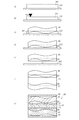
図1は、本発明の第1実施例に係る燃料電池100の模式的断面図である。図1に示すように、燃料電池100は、膜電極接合体(MEA)10、撥水層20,30、多孔体層40,50およびセパレータ60,70を含む。MEA10は、電解質層11および触媒層12,13から構成される。電解質層11は、例えば、プロトン導電性を有する固体高分子からなる。触媒層12,13は、例えば、白金を担持したカーボンから構成される。触媒層12,13中の白金は、水素のプロトン化およびプロトンと酸素との反応のための触媒として用いられる。触媒層12は電解質層11上に形成され、触媒層13は電解質層11下に形成されている。
FIG. 1 is a schematic cross-sectional view of a
撥水層20,30は、PTFE(ポリテトラフルオロエチレン)、カーボン等の撥水性、導電性およびガス透過性を備えた材料から構成される。撥水層20,30の撥水性、電気導電性およびガス透過性向上のためには、カーボンナノチューブを用いることが好ましい。ここで、撥水性を備えるとは、接触角が90°以上であることをいう。撥水層20,30の膜厚は、例えば、50μm程度である。撥水層20は触媒層12上に形成され、撥水層30は触媒層13下に形成されている。撥水層20,30のMEA10側の面は、多孔体層40,50の平面度よりも高い平面度を有するように形成されている。撥水層20,30それぞれのMEA10側の面の平面度は、例えば、10μm以下である。
The water repellent layers 20 and 30 are made of a material having water repellency, conductivity, and gas permeability such as PTFE (polytetrafluoroethylene) and carbon. In order to improve the water repellency, electrical conductivity and gas permeability of the water repellent layers 20 and 30, it is preferable to use carbon nanotubes. Here, having water repellency means that the contact angle is 90 ° or more. The film thickness of the water repellent layers 20 and 30 is, for example, about 50 μm. The
多孔体層40,50は、発泡焼結金属体等の導電性多孔体から構成される。多孔体層40,50は、ガスが流動するためのガス流路および触媒層にガスを供給するためのガス拡散層として機能する。本実施例においては、多孔体層40,50として、チタン発泡焼結金属体が用いられている。例えば、多孔体層40,50の膜厚は0.5mm程度であり、多孔体層40,50の発泡空孔の平均孔径は0.05mm〜3mm程度であり、粒子間空孔の平均孔径は0.1μm〜40μm程度であり、気孔率は40%〜99%程度である。多孔体層40,50は、ドクターブレード法等によって作製することができる。多孔体層40は撥水層20上に形成され、多孔体層50は撥水層30下に形成されている。
The porous body layers 40 and 50 are composed of a conductive porous body such as a foam sintered metal body. The
多孔体層40の下面側の一部は、撥水層20に埋め込まれ、固定されている。多孔体層40の下面側の一部は、多孔体層40の下面と撥水層20の上面との間に空隙がない程度に撥水層20に埋め込まれていることが好ましい。多孔体層50の上面側の一部は、撥水層30に埋め込まれ、固定されている。多孔体層50の上面側の一部は、多孔体層50の上面と撥水層30の下面との間に空隙がない程度に撥水層30に埋め込まれていることが好ましい。
A part of the lower surface side of the
セパレータ60,70は、ステンレス等の導電性材料から構成される。セパレータ60は多孔体層40上に形成され、セパレータ70は多孔体層50下に形成されている。セパレータ60,70の膜厚は、例えば、0.3mm程度である。図1においては説明の簡略化のために単セルが記載されているが、実際の燃料電池においてはこの単セルが複数積層されている。
The
続いて、燃料電池100の作用について説明する。まず、水素を含有する燃料ガスが多孔体層50に供給される。燃料ガスは、多孔体層50を流動しつつ、撥水層30を透過して触媒層13に到達する。触媒層13に到達した燃料ガス中の水素は、プロトンと電子とに分離される。プロトンは、電解質層11を伝導し、触媒層12に到達する。
Next, the operation of the
一方、酸素を含有する酸化剤ガスは多孔体層40に供給される。酸化剤ガスは、多孔体層40を流動しつつ、撥水層20を透過して触媒層12に到達する。触媒層12に到達した酸化剤ガス中の酸素とプロトンとから水が発生するとともに電力が発生する。発生した電力は、セパレータ60,70によって回収される。以上の動作によって、燃料電池100は発電を行う。
On the other hand, an oxidant gas containing oxygen is supplied to the
発電に伴って生成された発電生成水は、撥水層20を透過して多孔体層40に到達する。撥水層20は撥水性を有することから、発電生成水は、効率よく多孔体層40側に排水される。それにより、発電生成水が触媒層12に滞留することが抑制される。同様に、撥水層30側の水も効率よく排水される。その結果、燃料電池100の発電効率低下を抑制することができる。多孔体層40に到達した発電生成水は、酸化剤ガスの流動圧力によって、酸化剤ガスの流動方向に流動する。以上のことから、燃料電池100においては、発電生成水が効率良く排水される。
The power generation water generated along with the power generation passes through the
本実施例に係る燃料電池100においては、撥水層20,30のMEA10側の面の平面度が高いことから、撥水層20,30とMEA10との接触面積が増加する。それにより、撥水層20,30とMEA10との接触抵抗が低下する。その結果、燃料電池100の発電効率が向上する。また、撥水層20,30とMEA10との間の面圧がほぼ均一になる。それにより、MEA10に局部圧力がかかることが防止される。その結果、MEA10の破損が防止されるとともに、MEA10の耐久性が向上する。
In the
ここで、多孔体層40,50は、その製法に起因して表面に凹凸が形成されることが多い。しかしながら、多孔体層40が撥水層20に埋め込まれていることから、多孔体層40に対して圧力をかけなくても多孔体層40と撥水層20との間に十分な接触面積が得られる。特に、多孔体層40と撥水層20との間に空隙がなければ接触面積がさらに大きくなる。それにより、多孔体層40と撥水層20との間の接触抵抗が低下する。多孔体層50と撥水層30との間においても同様である。その結果、燃料電池100の発電効率が向上する。
Here, the
また、多孔体層40と撥水層20との間に十分な接触面積が得られると、発電に伴って発生する熱が多孔体層40に伝達しやすくなる。多孔体層50と撥水層30との間においても同様である。それにより、効率良く燃料電池100を冷却することができる。さらに、あらかじめ多孔体層40が撥水層20に埋め込まれていることから、多孔体層40と撥水層20との間の接触点に燃料ガスまたは酸化剤ガスに含まれる塵等の付着が防止される。それにより、多孔体層40と撥水層20との間の低接触抵抗を維持することができる。多孔体層50と撥水層30との間においても同様である。
In addition, when a sufficient contact area is obtained between the
また、凹凸を有する多孔体層40,50に圧力をかける必要がないことから、MEA10に局部圧力がかかることが防止される。その結果、MEA10の破損が防止されるとともに、MEA10の耐久性が向上する。また、多孔体層40,50に圧力をかける必要がないことから、多孔体層40,50の変形を抑制することができる。それにより、多孔体層40,50のガス透過度および排水性の低下を抑制することができる。
Moreover, since it is not necessary to apply pressure to the porous body layers 40 and 50 having irregularities, local pressure is prevented from being applied to the
ここで、一般的に、平面度が高い多孔体層の製造コストは非常に高くなり、品質管理が困難になる。多孔体層の平面度を向上させるためには、多孔体層に対して研磨または切削を行う等の二次加工を施す必要があるからである。また、二次加工の際には、多孔体層の表面および内部の形状が変化するおそれがあるからである。しかしながら、平面度が高い多孔体層を用いなくても本発明の効果を得ることができる。したがって、本発明によれば、生産コストを低減させることができるとともに、品質管理が容易になる。 Here, generally, the manufacturing cost of the porous body layer having high flatness becomes very high, and quality control becomes difficult. This is because in order to improve the flatness of the porous body layer, it is necessary to perform secondary processing such as polishing or cutting the porous body layer. Moreover, it is because the shape of the surface of a porous body layer and an inside may change in the case of secondary processing. However, the effect of the present invention can be obtained without using a porous layer having high flatness. Therefore, according to the present invention, the production cost can be reduced and quality control is facilitated.
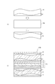
続いて、燃料電池100の製造方法について説明する。図2は、燃料電池100の製造方法を説明するための製造フロー図である。まず、図2(a)に示すように、型202の上にスラリー状の撥水剤201を塗布する。撥水剤201としては、スラリー状のPTFE、カーボン等を用いることができる。この場合の型202として、良好な離型性を有し、平面度が10μm程度のものを用いることが好ましい。例えば、PTFEを用いることができる。
Then, the manufacturing method of the
次に、図2(b)に示すように、スクリーニング等により、撥水剤201の膜厚を調整する。なお、撥水剤201として揮発性の低い材料を用いる場合には、時間をかけて撥水剤201の膜厚を調整することができる。したがって、スクリーニング等により膜厚調整を行わなくても、所定容積の金型に撥水剤を所定量流し込むことによって撥水剤の膜厚を調整することが可能になる。
Next, as shown in FIG. 2B, the film thickness of the
次いで、図2(c)に示すように、多孔体層40の下面側の一部が撥水剤201に浸るように、多孔体層40を撥水剤201上に配置する。この場合、多孔体層40の下面と撥水剤201の上面との間に空隙が存在しないように多孔体層40を撥水剤201に対して押し付けることが好ましい。なお、多孔体層40は、金属で構成されていることから、スラリー状の撥水剤201よりも変形しにくい。それにより、多孔体層40を撥水剤201に対して押し付ける場合でも、スラリー状の撥水剤201の粘度が低くなるように調整する必要がない。
Next, as shown in FIG. 2C, the
次に、図2(d)に示すように、撥水剤201を乾燥させ、撥水剤201の不要な部分をカットする。乾燥させた撥水剤201が図1の撥水層20に対応する。次いで、図2(e)に示すように、撥水層20および多孔体層40を脱型する。撥水層30および多孔体層50は、図2(a)〜図2(e)と同様の方法により作製することができる。
Next, as shown in FIG. 2D, the
次に、図2(f)に示すように、MEA10上に撥水層20および多孔体層40を配置し、MEA10下に撥水層30および多孔体層50を配置する。次いで、図2(g)に示すように、多孔体層40上にセパレータ60を配置し、多孔体層50下にセパレータ70を配置する。以上の工程により、燃料電池100が完成する。
Next, as shown in FIG. 2 (f), the
図2の製造方法によれば、多孔体層40が撥水剤201に浸されていることから、多孔体層40に対して圧力をかけなくても多孔体層40と乾燥後の撥水層20との間に十分な接触面積が得られる。特に、多孔体層40と撥水剤201との間に空隙がなければ、さらに大きな接触面積が得られる。それにより、多孔体層40と撥水層20との間の接触抵抗が低下する。同様に、多孔体層50と撥水層30との間の接触抵抗が低下する。
According to the manufacturing method of FIG. 2, since the
また、多孔体層40と撥水層20との間に十分な接触面積が得られることから、接触抵抗低減のために多孔体層40に圧力をかける必要がなくなる。多孔体層50に対しても同様である。それにより、MEA10に局部圧力がかかることが防止される。その結果、MEA10の破損が防止されるとともに、MEA10の耐久性が向上する。さらに、多孔体層40,50の変形を抑制することができる。それにより、多孔体層40,50のガス透気度および排水性の低下を抑制することができる。また、平面度が高い多孔体層を用いなくても本発明の効果を得ることができる。したがって、本実施例に係る製造方法によれば、生産コストを低減させることができるとともに、品質管理が容易になる。
In addition, since a sufficient contact area is obtained between the
また、撥水層20,30のMEA10側の平面度を向上させることができる。それにより、撥水層20,30とMEA10との接触抵抗が低下する。また、撥水層20,30とMEA10との間の面圧がほぼ均一になる。それにより、MEA10に局部圧力がかかることが防止される。その結果、MEA10の破損が防止されるとともに、MEA10の耐久性が向上する。
Further, the flatness of the water repellent layers 20 and 30 on the
なお、本実施例においては多孔体層40,50としてチタン発泡焼結金属体が用いられているが、それに限られない。例えば、ステンレス、ニッケル等の良好な耐食性を有する金属の発泡焼結体を用いることができる。また、金属炭化物が均一に分散した金属発泡体を用いることができる。例えば、ステンレス中にCr炭化物、FeCr炭化物等が均一に分散した金属発泡体を用いることができる。
In the present embodiment, a titanium foam sintered metal body is used as the
本実施例においては、多孔体層40,50が導電性多孔体層および金属多孔体に相当し、撥水層20,30が導電性層に相当し、多孔体層40および撥水層20または多孔体層50および撥水層30が燃料電池用導電性多孔体に相当し、撥水剤201が導電性スラリーに相当し、型202が平面プレートに相当する。
In this embodiment, the porous body layers 40 and 50 correspond to the conductive porous body layer and the metal porous body, the water repellent layers 20 and 30 correspond to the conductive layer, and the
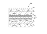
続いて、本発明の第2実施例に係る燃料電池100aについて説明する。図3は、燃料電池100aの模式的断面図である。図3に示すように、燃料電池100aが燃料電池100と異なる点は、多孔体層40のセパレータ60側に親水層80が形成されている点および多孔体層50のセパレータ70側に親水層90が形成されている点である。その他の点においては、燃料電池100aは燃料電池100と同様の構成を有する。なお、実施例1と同様の部位には同一符号を付すことで重複する説明を省略する。
Subsequently, a
親水層80,90は、PTFEにシリカ、チタニア等を混入させた親水性材料から構成され、導電性およびガス拡散性を有する。ここで、親水性を備えるとは、接触角が90°未満であることをいう。親水層80,90の膜厚は、例えば、50μm程度である。親水層80のセパレータ60側の面および親水層90のセパレータ70側の面は、平面度が10μm以下になるように形成されている。多孔体層40の上面側の一部は、親水層80に埋め込まれ、固定されている。多孔体層40の上面側の一部は、多孔体層40の上面と親水層80との間に空隙がない程度に親水層80に埋め込まれていることが好ましい。多孔体層50の下面側の一部も同様に、親水層90に埋め込まれている。
The hydrophilic layers 80 and 90 are made of a hydrophilic material in which silica, titania or the like is mixed in PTFE, and have conductivity and gas diffusibility. Here, having hydrophilicity means that the contact angle is less than 90 °. The film thickness of the
本実施例に係る燃料電池100aにおいては、親水層80とセパレータ60との接触面積および親水層90とセパレータ70との接触面積が増加する。それにより、燃料電池100aの発電効率がより向上する。また、MEA10における発電反応に伴って発生する熱がセパレータ60,70に伝達しやすくなる。それにより、より効率良く燃料電池100aを冷却することができる。
In the
さらに、あらかじめ多孔体層40が親水層80に埋め込まれていることから、多孔体層40と親水層80との間の接触点に燃料ガスまたは酸化剤ガスに含まれる塵等が付着することが防止される。それにより、多孔体層40と親水層80との間の低接触抵抗を維持することができる。多孔体層50と親水層90との間においても同様である。また、親水層80は親水性を備えていることから、撥水層20を透過した発電生成水をセパレータ60側に効率良く排水することができる。同様に、撥水層30側の水も親水層90によって効率良く排水される。
Furthermore, since the
図4は、燃料電池100aの製造方法を説明するための製造フロー図である。まず、図4(a)に示すように、型204上に所定厚になるように調整されたスラリー状の親水剤203と、図2(e)で作製した撥水層20および多孔体層40とを準備する。型204は、図2の型202と同様の平面度を有することが好ましい。親水剤203としては、スラリー状でシリカ、チタニア等を含有するPTFE、SBR(スチレンブタジエンラバー)、カーボン等を用いることができる。
FIG. 4 is a manufacturing flow diagram for explaining a manufacturing method of the
次に、図4(b)に示すように、多孔体層40の撥水層20と反対側の一部が親水剤203に浸るように、多孔体層40を親水剤203上に配置する。この場合、多孔体層40と親水剤203との間に空隙が存在しないように多孔体層40を親水剤203に対して押し付けることが好ましい。次いで、図4(c)に示すように、親水剤203を乾燥させ、親水剤203の不要な部分をカットする。乾燥させた親水剤201が図3の親水層80に対応する。親水層90および多孔体層50は、図4(a)〜図4(c)と同様の方法により作製することができる。
Next, as shown in FIG. 4B, the
次に、図4(d)に示すように、MEA10上に撥水層20、多孔体層40および親水層80を配置し、MEA10下に撥水層30、多孔体層50および親水層90を配置する。次いで、図4(e)に示すように、親水層80上にセパレータ60を配置し、親水層90下にセパレータ70を配置する。以上の工程により、燃料電池100aが完成する。
Next, as shown in FIG. 4D, the
図4の製造方法によれば、多孔体層40が親水剤203に浸されていることから、多孔体層40に対して圧力をかけなくても多孔体層40と乾燥後の親水層80との間に十分な接触面積が得られる。特に、多孔体層40と親水剤203との間に空隙がなければ、さらに大きな接触面積が得られる。それにより、多孔体層40と親水層80との間の接触抵抗が低下する。同様に、多孔体層50と親水層90との間の接触抵抗が低下する。
According to the manufacturing method of FIG. 4, since the
本実施例においては、多孔体層40、撥水層20および親水層80または多孔体層50、撥水層30および親水層90が燃料電池用導電性多孔体に相当し、親水層80,90が導電性層に相当し、親水剤204が導電性スラリーに相当し、型204が平面プレートに相当する。
In this embodiment, the
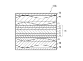
続いて、本発明の第3実施例に係る燃料電池100bについて説明する。図5は、燃料電池100bの模式的断面図である。図5に示すように、燃料電池100bが図1の燃料電池100と異なる点は、MEA10の代わりにMEA10bが設けられている点、撥水層20の代わりに親水層21が設けられている点および撥水層30の代わりに親水層31が設けられている点である。MEA10bがMEA10と異なる点は、触媒層12上にガス拡散層14が設けられている点および触媒層13下にガス拡散層15が設けられている点である。その他の点においては、燃料電池100bは燃料電池100と同様の構成を有する。なお、実施例1と同様の部位には同一符号を付すことで重複する説明を省略する。
Subsequently, a
ガス拡散層14,15は、例えば、カーボン繊維およびPTFEを含むカーボンペーパ、カーボンクロス等から構成され、撥水性、導電性およびガス拡散性を備える。ガス拡散層14,15の膜厚は、例えば、150μm程度である。親水層21,31は、PTFEにシリカ、チタニア等を混入させた親水性材料から構成され、導電性およびガス拡散性を有する。親水層21,31の膜厚は、例えば、50μm程度である。
The gas diffusion layers 14 and 15 are made of, for example, carbon paper and carbon cloth containing carbon fibers and PTFE, and have water repellency, conductivity, and gas diffusibility. The film thickness of the gas diffusion layers 14 and 15 is, for example, about 150 μm. The hydrophilic layers 21 and 31 are made of a hydrophilic material obtained by mixing PTFE with silica, titania or the like, and have conductivity and gas diffusibility. The film thickness of the
多孔体層40の下面側の一部は、親水層21に埋め込まれ、固定されている。多孔体層40の下面側の一部は、多孔体層40の下面と親水層21の上面との間に空隙がない程度に親水層21に埋め込まれていることが好ましい。多孔体層50の上面側の一部は、親水層31に埋め込まれ、固定されている。多孔体層50の上面側の一部は、多孔体層50の上面と親水層31の下面との間に空隙がない程度に親水層31に埋め込まれていることが好ましい。親水層21,31は、図2に示した撥水層20,30の形成方法と同様の方法により形成することができる。
A part of the lower surface side of the
本実施例においては、ガス拡散層14が撥水性を有しかつ親水層21が親水性を有することから、発電生成水は、効率よく親水層21側に排水される。それにより、発電生成水が触媒層12に滞留することが抑制される。同様に、ガス拡散層15側の水も親水層31によって効率よく排水される。その結果、燃料電池100bの発電効率低下を抑制することができる。
In this embodiment, since the
図6は、燃料電池100bの製造方法を説明するための製造フロー図である。図6(a)に示すように、親水層21および多孔体層40、親水層31および多孔体層50ならびにMEA10bを、MEA10bの上面と親水層21とが対向しMEA10bの下面と親水層31とが対向するように配置する。次に、図6(b)に示すように、多孔体層40上にセパレータ60を配置して多孔体層50下にセパレータ70を配置する。以上の工程により、燃料電池100bが完成する。
FIG. 6 is a manufacturing flow diagram for explaining a manufacturing method of the
続いて、本発明の第4実施例に係る燃料電池100cについて説明する。図7は、燃料電池100cの模式的断面図である。燃料電池100cが図5の燃料電池100bと異なる点は、多孔体層40のセパレータ60側に親水層80cが形成されている点および多孔体層50のセパレータ70側に親水層90cが形成されている点である。その他の点においては、燃料電池100cは燃料電池100bと同様の構成を有する。なお、実施例3と同様の部位には同一符号を付すことで重複する説明を省略する。
Subsequently, a
親水層80c,90cは、SBRにシリカ、チタニア等を混入させた親水性材料から構成され、導電性およびガス拡散性を有する。親水層21の親水性よりも親水層80cの親水性の方が高く設定され、親水層31の親水性よりも親水層90cの親水性の方が高く設定されている。
The
本実施例においては、ガス拡散層14が撥水性を有しかつ親水層21が親水性を有することから、発電生成水は、効率よく親水層21側に排水される。さらに、親水層80cが親水層21よりも高い親水性を有することから、親水層21から親水層80cに水が吸引される。それにより、MEA10bにおける発電生成水の滞留を抑制することができる。その結果、燃料電池100cの発電効率低下をより抑制することができる。ガス拡散層15側においても、親水層31および親水層90cにより効率良く排水される。
In this embodiment, since the
なお、多孔体層40、親水層21および親水層80cまたは多孔体層50、親水層31および親水層90cが燃料電池用導電性多孔体に相当する。
The
10,10b MEA
11 電解質膜
12,13 触媒層
14,15 ガス拡散層
20,30 撥水層
40,50 多孔体層
60,70 セパレータ
21,31,80,90 親水層
100,100a,100b 燃料電池
201 撥水剤
203 親水剤
10, 10b MEA
DESCRIPTION OF
Claims (16)
前記金属多孔体の一面側に配置され、ガス透過性を有する導電性層とを備え、
前記金属多孔体の一面側の少なくとも一部は、前記導電性層の他面に埋め込まれ、
前記導電性層の一面側の平面度は、前記金属多孔体の一面側の平面度よりも高いことを特徴とする燃料電池用導電性多孔体。 A metal porous body,
A conductive layer disposed on one side of the porous metal body and having gas permeability;
At least a part of one surface side of the metal porous body is embedded in the other surface of the conductive layer,
The conductive porous body for a fuel cell, wherein the flatness of one surface side of the conductive layer is higher than the flatness of one surface side of the metal porous body.
電解質膜の両面に触媒層が形成され、少なくとも一方の前記触媒層と前記燃料電池用導電性多孔体の一面とが対向するように配置されたMEAとを備えることを特徴とする燃料電池。 A conductive porous body for a fuel cell according to any one of claims 1 to 4,
A fuel cell comprising: a catalyst layer formed on both surfaces of an electrolyte membrane, and an MEA disposed so that at least one of the catalyst layer and one surface of the conductive porous body for a fuel cell face each other.
電解質膜の両面に触媒層およびガス拡散層が順に形成され、少なくとも一方の前記ガス拡散層と前記燃料電池用導電性多孔体の一面とが対向するように配置されたMEAとを備えることを特徴とする燃料電池。 A conductive porous body for a fuel cell according to any one of claims 1 to 4,
A catalyst layer and a gas diffusion layer are sequentially formed on both surfaces of the electrolyte membrane, and at least one of the gas diffusion layer and an MEA arranged so that one surface of the conductive porous body for a fuel cell faces each other are provided. A fuel cell.
前記導電性スラリー上に導電性多孔体を積層する工程と、
前記導電性スラリーを乾燥させてガス透過性を有する導電性層を形成する工程と、
前記導電性層と前記平面プレートとを分離する工程とを含むことを特徴とする燃料電池用導電性多孔体の製造方法。 Arranging the conductive slurry on the flat plate to have a predetermined thickness;
Laminating a conductive porous body on the conductive slurry;
Drying the conductive slurry to form a gas permeable conductive layer;
A method for producing a conductive porous body for a fuel cell, comprising the step of separating the conductive layer and the flat plate.
The method for manufacturing a fuel cell according to claim 15, wherein the conductive layer has hydrophilicity.
Priority Applications (8)
| Application Number | Priority Date | Filing Date | Title |
|---|---|---|---|
| JP2005338181A JP5061454B2 (en) | 2005-11-24 | 2005-11-24 | Fuel cell |
| CA2625617A CA2625617C (en) | 2005-11-24 | 2006-11-23 | Electrically conductive porous body for a fuel cell, fuel cell having same, and method of manufacturing same |
| EP06820957A EP1961062B1 (en) | 2005-11-24 | 2006-11-23 | Electrically conductive porous body for a fuel cell, fuel cell having same, and method of manufacturing same |
| KR1020087012302A KR100968237B1 (en) | 2005-11-24 | 2006-11-23 | Electrically conductive porous body for a fuel cell, fuel cell having same, method of manufacturing same |
| US12/083,243 US7811715B2 (en) | 2005-11-24 | 2006-11-23 | Electrically conductive porous body for a fuel cell, fuel cell having same, and method of manufacturing same |
| PCT/IB2006/003323 WO2007060527A2 (en) | 2005-11-24 | 2006-11-23 | Electrically conductive porous body for a fuel cell having same, and method of manufacturing same |
| DE602006016329T DE602006016329D1 (en) | 2005-11-24 | 2006-11-23 | ELECTRICALLY CONDUCTIVE POROUS BODY FOR A FUEL CELL THEREFOR AND METHOD OF MANUFACTURING THEREOF |
| CN2006800441741A CN101317292B (en) | 2005-11-24 | 2006-11-23 | Electrically conductive porous body for a fuel cell having same, and method of manufacturing same |
Applications Claiming Priority (1)
| Application Number | Priority Date | Filing Date | Title |
|---|---|---|---|
| JP2005338181A JP5061454B2 (en) | 2005-11-24 | 2005-11-24 | Fuel cell |
Publications (2)
| Publication Number | Publication Date |
|---|---|
| JP2007149357A true JP2007149357A (en) | 2007-06-14 |
| JP5061454B2 JP5061454B2 (en) | 2012-10-31 |
Family
ID=37969598
Family Applications (1)
| Application Number | Title | Priority Date | Filing Date |
|---|---|---|---|
| JP2005338181A Expired - Fee Related JP5061454B2 (en) | 2005-11-24 | 2005-11-24 | Fuel cell |
Country Status (8)
| Country | Link |
|---|---|
| US (1) | US7811715B2 (en) |
| EP (1) | EP1961062B1 (en) |
| JP (1) | JP5061454B2 (en) |
| KR (1) | KR100968237B1 (en) |
| CN (1) | CN101317292B (en) |
| CA (1) | CA2625617C (en) |
| DE (1) | DE602006016329D1 (en) |
| WO (1) | WO2007060527A2 (en) |
Cited By (7)
| Publication number | Priority date | Publication date | Assignee | Title |
|---|---|---|---|---|
| JP2008108456A (en) * | 2006-10-23 | 2008-05-08 | Equos Research Co Ltd | Electrode for fuel cell, cell of fuel cell, and stack of fuel cells |
| JP2009021235A (en) * | 2007-06-15 | 2009-01-29 | Sumitomo Chemical Co Ltd | Membrane-electrode-gas diffusion layer assembly and fuel cell having the same |
| JP2009277503A (en) * | 2008-05-14 | 2009-11-26 | Toyota Motor Corp | Fuel cell, and fuel cell stack |
| JP2010244910A (en) * | 2009-04-08 | 2010-10-28 | Toyota Motor Corp | Fuel cell |
| WO2015004969A1 (en) * | 2013-07-10 | 2015-01-15 | 日産自動車株式会社 | Fuel cell unit cell |
| KR20160140731A (en) | 2014-03-31 | 2016-12-07 | 스미토모덴키고교가부시키가이샤 | Collector for fuel cells, and fuel cell |
| WO2020045618A1 (en) * | 2018-08-31 | 2020-03-05 | Tdk株式会社 | Oxygen reduction electrode, metal-air battery, alkaline fuel cell, and method for producing oxygen reduction electrode |
Families Citing this family (4)
| Publication number | Priority date | Publication date | Assignee | Title |
|---|---|---|---|---|
| US8617759B2 (en) | 2010-03-19 | 2013-12-31 | GM Global Technology Operations LLC | Selectively coated bipolar plates for water management and freeze start in PEM fuel cells |
| CN104205460B (en) * | 2012-04-04 | 2016-11-09 | 日产自动车株式会社 | The manufacture method of membrane electrode assembly, fuel cell, fuel cell pack and membrane electrode assembly |
| KR101321463B1 (en) | 2012-06-28 | 2013-10-28 | 주식회사 셀모티브 | Fuel cell and method of manufacturing thereof |
| CN114725399B (en) * | 2022-04-28 | 2023-10-17 | 一汽解放汽车有限公司 | Low-temperature cold start adaptive gas diffusion layer, preparation method thereof and fuel cell |
Citations (6)
| Publication number | Priority date | Publication date | Assignee | Title |
|---|---|---|---|---|
| US3948684A (en) * | 1972-11-01 | 1976-04-06 | Her Majesty The Queen In Right Of Canada As Represented By The Minister Of National Defence | Oxygen electrode and process for making the same |
| JPH11241196A (en) * | 1998-02-26 | 1999-09-07 | Japan Storage Battery Co Ltd | Solid high molecular electrolyte-catalyst combined electrode |
| JP2003282068A (en) * | 2002-03-25 | 2003-10-03 | Sumitomo Electric Ind Ltd | Metal porous body and solid high polymer type fuel cell using the same |
| JP2004169165A (en) * | 2002-11-22 | 2004-06-17 | Choichi Furuya | Method for producing gas diffusion electrode |
| JP2005158324A (en) * | 2003-11-21 | 2005-06-16 | Honda Motor Co Ltd | Fuel cell |
| WO2005081339A1 (en) * | 2004-02-23 | 2005-09-01 | Matsushita Electric Industrial Co., Ltd. | Gas diffusion layer and fuel cell using same |
Family Cites Families (11)
| Publication number | Priority date | Publication date | Assignee | Title |
|---|---|---|---|---|
| JPS5120158A (en) * | 1974-08-09 | 1976-02-18 | Mitsui Mining & Smelting Co | Kongobutsuno shoriho |
| US5266177A (en) * | 1986-03-07 | 1993-11-30 | Tanaka Kikinzoku Kogyo K.K. | Process for preparing reaction layer of gas permeable electrode |
| US5350643A (en) * | 1992-06-02 | 1994-09-27 | Hitachi, Ltd. | Solid polymer electrolyte type fuel cell |
| JPH07220734A (en) * | 1994-01-31 | 1995-08-18 | Mitsubishi Heavy Ind Ltd | Manufacture of gas diffusion electrode |
| US6183898B1 (en) | 1995-11-28 | 2001-02-06 | Hoescht Research & Technology Deutschland Gmbh & Co. Kg | Gas diffusion electrode for polymer electrolyte membrane fuel cells |
| JP2000328279A (en) | 1999-05-25 | 2000-11-28 | Fuji Electric Co Ltd | Production of power feeding body for electrochemical cell |
| EP1353391A4 (en) * | 2000-11-16 | 2008-08-06 | Mitsubishi Materials Corp | Solid electrolyte type fuel cell and air electrode collector for use therein |
| US6743543B2 (en) * | 2001-10-31 | 2004-06-01 | Motorola, Inc. | Fuel cell using variable porosity gas diffusion material |
| JP4346874B2 (en) | 2002-08-08 | 2009-10-21 | 株式会社大阪チタニウムテクノロジーズ | Porous conductive plate |
| US7846591B2 (en) | 2004-02-17 | 2010-12-07 | Gm Global Technology Operations, Inc. | Water management layer on flowfield in PEM fuel cell |
| JP4696545B2 (en) | 2004-12-08 | 2011-06-08 | トヨタ自動車株式会社 | Fuel cell |
-
2005
- 2005-11-24 JP JP2005338181A patent/JP5061454B2/en not_active Expired - Fee Related
-
2006
- 2006-11-23 CN CN2006800441741A patent/CN101317292B/en not_active Expired - Fee Related
- 2006-11-23 EP EP06820957A patent/EP1961062B1/en not_active Not-in-force
- 2006-11-23 DE DE602006016329T patent/DE602006016329D1/en active Active
- 2006-11-23 CA CA2625617A patent/CA2625617C/en not_active Expired - Fee Related
- 2006-11-23 US US12/083,243 patent/US7811715B2/en not_active Expired - Fee Related
- 2006-11-23 KR KR1020087012302A patent/KR100968237B1/en not_active IP Right Cessation
- 2006-11-23 WO PCT/IB2006/003323 patent/WO2007060527A2/en active Application Filing
Patent Citations (6)
| Publication number | Priority date | Publication date | Assignee | Title |
|---|---|---|---|---|
| US3948684A (en) * | 1972-11-01 | 1976-04-06 | Her Majesty The Queen In Right Of Canada As Represented By The Minister Of National Defence | Oxygen electrode and process for making the same |
| JPH11241196A (en) * | 1998-02-26 | 1999-09-07 | Japan Storage Battery Co Ltd | Solid high molecular electrolyte-catalyst combined electrode |
| JP2003282068A (en) * | 2002-03-25 | 2003-10-03 | Sumitomo Electric Ind Ltd | Metal porous body and solid high polymer type fuel cell using the same |
| JP2004169165A (en) * | 2002-11-22 | 2004-06-17 | Choichi Furuya | Method for producing gas diffusion electrode |
| JP2005158324A (en) * | 2003-11-21 | 2005-06-16 | Honda Motor Co Ltd | Fuel cell |
| WO2005081339A1 (en) * | 2004-02-23 | 2005-09-01 | Matsushita Electric Industrial Co., Ltd. | Gas diffusion layer and fuel cell using same |
Cited By (10)
| Publication number | Priority date | Publication date | Assignee | Title |
|---|---|---|---|---|
| JP2008108456A (en) * | 2006-10-23 | 2008-05-08 | Equos Research Co Ltd | Electrode for fuel cell, cell of fuel cell, and stack of fuel cells |
| JP2009021235A (en) * | 2007-06-15 | 2009-01-29 | Sumitomo Chemical Co Ltd | Membrane-electrode-gas diffusion layer assembly and fuel cell having the same |
| JP2009277503A (en) * | 2008-05-14 | 2009-11-26 | Toyota Motor Corp | Fuel cell, and fuel cell stack |
| JP2010244910A (en) * | 2009-04-08 | 2010-10-28 | Toyota Motor Corp | Fuel cell |
| WO2015004969A1 (en) * | 2013-07-10 | 2015-01-15 | 日産自動車株式会社 | Fuel cell unit cell |
| JP6066150B2 (en) * | 2013-07-10 | 2017-01-25 | 日産自動車株式会社 | Single cell for fuel cell |
| US9837676B2 (en) | 2013-07-10 | 2017-12-05 | Nissan Motor Co., Ltd. | Fuel cell single cell |
| KR20160140731A (en) | 2014-03-31 | 2016-12-07 | 스미토모덴키고교가부시키가이샤 | Collector for fuel cells, and fuel cell |
| US10797323B2 (en) | 2014-03-31 | 2020-10-06 | Sumitomo Electric Industries, Ltd. | Current collector for fuel cell, and fuel cell |
| WO2020045618A1 (en) * | 2018-08-31 | 2020-03-05 | Tdk株式会社 | Oxygen reduction electrode, metal-air battery, alkaline fuel cell, and method for producing oxygen reduction electrode |
Also Published As
| Publication number | Publication date |
|---|---|
| US20090111001A1 (en) | 2009-04-30 |
| CA2625617A1 (en) | 2007-05-31 |
| EP1961062B1 (en) | 2010-08-18 |
| KR100968237B1 (en) | 2010-07-06 |
| WO2007060527A3 (en) | 2007-08-09 |
| KR20080056024A (en) | 2008-06-19 |
| JP5061454B2 (en) | 2012-10-31 |
| US7811715B2 (en) | 2010-10-12 |
| CN101317292A (en) | 2008-12-03 |
| EP1961062A2 (en) | 2008-08-27 |
| DE602006016329D1 (en) | 2010-09-30 |
| CN101317292B (en) | 2010-12-22 |
| WO2007060527A2 (en) | 2007-05-31 |
| CA2625617C (en) | 2011-07-19 |
Similar Documents
| Publication | Publication Date | Title |
|---|---|---|
| JP5061454B2 (en) | Fuel cell | |
| US9123962B2 (en) | Flow battery having electrodes with a plurality of different pore sizes and or different layers | |
| KR101747456B1 (en) | Gas diffusion layer member for solid polymer fuel cells, and solid polymer fuel cell | |
| CA2875821A1 (en) | Flow structures for use with an electrochemical cell | |
| JP2008218411A (en) | Gas diffusion layer in which diffusivity in active area is controlled | |
| WO2015145128A1 (en) | Process of manufacturing a catalyst-coated membrane-seal assembly | |
| JP4959945B2 (en) | Polymer electrolyte fuel cell | |
| US9640823B2 (en) | Manufacturing method of membrane electrode assembly | |
| JP5364980B2 (en) | Fuel cell | |
| JP2008146928A (en) | Gas diffusing electrode for fuel cell and its manufacturing method | |
| JP5838570B2 (en) | Membrane electrode assembly in polymer electrolyte fuel cell | |
| JP2009277370A (en) | Membrane electrode assembly | |
| JP5245440B2 (en) | Manufacturing method of membrane-electrode assembly for fuel cell | |
| JP2008041348A (en) | Polymer electrolyte fuel cell and its manufacturing method | |
| JP2011070991A (en) | Polymer electrolyte fuel cell single cell, production method thereof, and fuel cell stack having same | |
| JP2011049179A (en) | Membrane-electrode assembly for polymer electrolyte fuel cell and gas diffusion electrode substrate | |
| JP2008226601A (en) | Membrane-membrane reinforcing member assembly, membrane-catalyst layer assembly, membrane-electrode assembly, polymer electrolyte fuel cell, and manufacturing method of membrane-membrane reinforcing member assembly | |
| JP2006040631A (en) | Polymer electrolyte membrane and polymer electrolyte fuel cell | |
| JP2008300325A (en) | Fuel cell | |
| JP2003142110A (en) | Electrode for fuel cell and fuel cell | |
| JP2006004808A (en) | Pressurization method of fuel cell material | |
| JP2007328936A (en) | Fuel cell, catalytic electrode layer therefor, and manufacturing method thereof | |
| JP2018077980A (en) | Method of manufacturing membrane electrode assembly | |
| JP2005116180A (en) | Fuel cell equipped with diffusion layer having function of separator also; and material for diffusion layer | |
| GB2510962A (en) | Fuel cells and fuel cell electrodes |
Legal Events
| Date | Code | Title | Description |
|---|---|---|---|
| A621 | Written request for application examination |
Free format text: JAPANESE INTERMEDIATE CODE: A621 Effective date: 20081003 |
|
| A977 | Report on retrieval |
Free format text: JAPANESE INTERMEDIATE CODE: A971007 Effective date: 20110415 |
|
| A131 | Notification of reasons for refusal |
Free format text: JAPANESE INTERMEDIATE CODE: A131 Effective date: 20110426 |
|
| A521 | Request for written amendment filed |
Free format text: JAPANESE INTERMEDIATE CODE: A523 Effective date: 20110621 |
|
| A02 | Decision of refusal |
Free format text: JAPANESE INTERMEDIATE CODE: A02 Effective date: 20120207 |
|
| A521 | Request for written amendment filed |
Free format text: JAPANESE INTERMEDIATE CODE: A523 Effective date: 20120426 |
|
| A911 | Transfer to examiner for re-examination before appeal (zenchi) |
Free format text: JAPANESE INTERMEDIATE CODE: A911 Effective date: 20120507 |
|
| A131 | Notification of reasons for refusal |
Free format text: JAPANESE INTERMEDIATE CODE: A131 Effective date: 20120605 |
|
| A521 | Request for written amendment filed |
Free format text: JAPANESE INTERMEDIATE CODE: A523 Effective date: 20120618 |
|
| TRDD | Decision of grant or rejection written | ||
| A01 | Written decision to grant a patent or to grant a registration (utility model) |
Free format text: JAPANESE INTERMEDIATE CODE: A01 Effective date: 20120710 |
|
| A01 | Written decision to grant a patent or to grant a registration (utility model) |
Free format text: JAPANESE INTERMEDIATE CODE: A01 |
|
| A61 | First payment of annual fees (during grant procedure) |
Free format text: JAPANESE INTERMEDIATE CODE: A61 Effective date: 20120723 |
|
| FPAY | Renewal fee payment (event date is renewal date of database) |
Free format text: PAYMENT UNTIL: 20150817 Year of fee payment: 3 |
|
| LAPS | Cancellation because of no payment of annual fees |