JP2007125901A - Vehicular turn signal system with function of holding hazard state - Google Patents
Vehicular turn signal system with function of holding hazard state Download PDFInfo
- Publication number
- JP2007125901A JP2007125901A JP2005317757A JP2005317757A JP2007125901A JP 2007125901 A JP2007125901 A JP 2007125901A JP 2005317757 A JP2005317757 A JP 2005317757A JP 2005317757 A JP2005317757 A JP 2005317757A JP 2007125901 A JP2007125901 A JP 2007125901A
- Authority
- JP
- Japan
- Prior art keywords
- winker
- hazard
- current
- switch
- relay
- Prior art date
- Legal status (The legal status is an assumption and is not a legal conclusion. Google has not performed a legal analysis and makes no representation as to the accuracy of the status listed.)
- Granted
Links
Images


Classifications
-
- B—PERFORMING OPERATIONS; TRANSPORTING
- B62—LAND VEHICLES FOR TRAVELLING OTHERWISE THAN ON RAILS
- B62J—CYCLE SADDLES OR SEATS; AUXILIARY DEVICES OR ACCESSORIES SPECIALLY ADAPTED TO CYCLES AND NOT OTHERWISE PROVIDED FOR, e.g. ARTICLE CARRIERS OR CYCLE PROTECTORS
- B62J6/00—Arrangement of optical signalling or lighting devices on cycles; Mounting or supporting thereof; Circuits therefor
- B62J6/16—Arrangement of switches
-
- B—PERFORMING OPERATIONS; TRANSPORTING
- B60—VEHICLES IN GENERAL
- B60Q—ARRANGEMENT OF SIGNALLING OR LIGHTING DEVICES, THE MOUNTING OR SUPPORTING THEREOF OR CIRCUITS THEREFOR, FOR VEHICLES IN GENERAL
- B60Q1/00—Arrangement of optical signalling or lighting devices, the mounting or supporting thereof or circuits therefor
- B60Q1/26—Arrangement of optical signalling or lighting devices, the mounting or supporting thereof or circuits therefor the devices being primarily intended to indicate the vehicle, or parts thereof, or to give signals, to other traffic
- B60Q1/34—Arrangement of optical signalling or lighting devices, the mounting or supporting thereof or circuits therefor the devices being primarily intended to indicate the vehicle, or parts thereof, or to give signals, to other traffic for indicating change of drive direction
-
- B—PERFORMING OPERATIONS; TRANSPORTING
- B60—VEHICLES IN GENERAL
- B60Q—ARRANGEMENT OF SIGNALLING OR LIGHTING DEVICES, THE MOUNTING OR SUPPORTING THEREOF OR CIRCUITS THEREFOR, FOR VEHICLES IN GENERAL
- B60Q1/00—Arrangement of optical signalling or lighting devices, the mounting or supporting thereof or circuits therefor
- B60Q1/26—Arrangement of optical signalling or lighting devices, the mounting or supporting thereof or circuits therefor the devices being primarily intended to indicate the vehicle, or parts thereof, or to give signals, to other traffic
- B60Q1/46—Arrangement of optical signalling or lighting devices, the mounting or supporting thereof or circuits therefor the devices being primarily intended to indicate the vehicle, or parts thereof, or to give signals, to other traffic for giving flashing caution signals during drive, other than signalling change of direction, e.g. flashing the headlights or hazard lights
-
- B—PERFORMING OPERATIONS; TRANSPORTING
- B60—VEHICLES IN GENERAL
- B60Q—ARRANGEMENT OF SIGNALLING OR LIGHTING DEVICES, THE MOUNTING OR SUPPORTING THEREOF OR CIRCUITS THEREFOR, FOR VEHICLES IN GENERAL
- B60Q1/00—Arrangement of optical signalling or lighting devices, the mounting or supporting thereof or circuits therefor
- B60Q1/26—Arrangement of optical signalling or lighting devices, the mounting or supporting thereof or circuits therefor the devices being primarily intended to indicate the vehicle, or parts thereof, or to give signals, to other traffic
- B60Q1/50—Arrangement of optical signalling or lighting devices, the mounting or supporting thereof or circuits therefor the devices being primarily intended to indicate the vehicle, or parts thereof, or to give signals, to other traffic for indicating other intentions or conditions, e.g. request for waiting or overtaking
- B60Q1/52—Arrangement of optical signalling or lighting devices, the mounting or supporting thereof or circuits therefor the devices being primarily intended to indicate the vehicle, or parts thereof, or to give signals, to other traffic for indicating other intentions or conditions, e.g. request for waiting or overtaking for indicating emergencies
-
- B—PERFORMING OPERATIONS; TRANSPORTING
- B62—LAND VEHICLES FOR TRAVELLING OTHERWISE THAN ON RAILS
- B62J—CYCLE SADDLES OR SEATS; AUXILIARY DEVICES OR ACCESSORIES SPECIALLY ADAPTED TO CYCLES AND NOT OTHERWISE PROVIDED FOR, e.g. ARTICLE CARRIERS OR CYCLE PROTECTORS
- B62J6/00—Arrangement of optical signalling or lighting devices on cycles; Mounting or supporting thereof; Circuits therefor
- B62J6/01—Electric circuits
Abstract
Description
本発明は、車両のハザード保持機能付きウインカ装置に関する。 The present invention relates to a winker device with a hazard holding function for a vehicle.
自動2輪車等の車両では、非常時に車道で一時停車をする際、車両の状況を他の車両等に認識させるために、ハザードスイッチを操作してウインカリレーを動作させ、前後左右のウインカを同時に点滅させるハザード機構が備えられている(例えば、特許文献1参照。)。 In vehicles such as motorcycles, when temporarily stopping on a roadway in an emergency, in order to make other vehicles recognize the situation of the vehicle, the hazard switch is operated and the blinker relay is operated, A hazard mechanism that flashes simultaneously is provided (for example, see Patent Document 1).
特許文献1に記載のハザード機構は、メインスイッチに並列に接続した接点を有し、メインスイッチをオンした時にのみハザードスイッチの操作によって動作するリレーを設けている。そして、メインスイッチがオンの状態でハザードスイッチを操作すると、リレーが動作して接点が閉じ、その後メインスイッチをオフにしても接点を介してウインカに通電することが可能となる。さらに、ハザードスイッチを解除すると接点が開くので、その後メインスイッチがオフの状態でハザードスイッチを操作してもハザード機能は作動しない。従って、車両を離れる際にキーを抜いてもハザード状態を保持することができ、他人の悪戯によるウインカの点滅を防止することができる。
ところで、特許文献1に記載の車両のハザード機構は、ウインカリレーの他に新たにハザード保持機能のためのリレーが必要となるので、部品点数及び配線工数の増加等、コストアップを招くという課題がある。 By the way, since the hazard mechanism of the vehicle described in Patent Document 1 requires a relay for a hazard holding function in addition to the blinker relay, there is a problem that the cost increases such as an increase in the number of parts and wiring man-hours. is there.
本発明は、上記事情に鑑みてなされたものであって、その目的は、比較的簡単かつ安価な構成で、車両を離れる際にキーを抜いてもハザード状態を保持することができる車両のハザード保持機能付きウインカ装置を提供することにある。 The present invention has been made in view of the above circumstances, and an object of the present invention is a vehicle hazard capable of maintaining a hazard state even when the key is removed when leaving the vehicle with a relatively simple and inexpensive configuration. An object of the present invention is to provide a winker device with a holding function.
上記目的を達成するために、請求項1に係る発明は、キー操作により車両の電源をオン/オフするメインスイッチと、メインスイッチをオンした際に、車両の左右のウインカを点滅するための電流を出力するウインカリレーと、ウインカリレーの出力を左右いずれかのウインカに選択して接続するウインカスイッチと、ウインカリレーの出力を左右のウインカに一括して接続するハザードスイッチと、を有する車両のハザード保持機能付きウインカ装置であって、ウインカリレーは、電源と常時接続され、且つ、所定の条件下でメインスイッチをオフした際に、ウインカを点滅するための電流を保持することを特徴とする。 In order to achieve the above object, the invention according to claim 1 includes a main switch for turning on / off a vehicle by a key operation, and a current for blinking the left and right turn signals of the vehicle when the main switch is turned on. Of a vehicle having a turn signal relay for outputting a turn signal, a turn signal switch for selecting and connecting the turn signal output to either the left or right turn signal, and a hazard switch for connecting the turn signal relay outputs to the left and right turn signals at once. The winker device with a holding function is characterized in that the winker relay is always connected to a power source and holds a current for blinking the winker when the main switch is turned off under a predetermined condition.
請求項2に係る発明は、請求項1の構成に加えて、ウインカリレーは、ウインカを点滅するための電流を検出する電流検出部を備え、ウインカリレーは、電流検出部によって、ハザードスイッチをオンにした場合に相当する第1の所定電流を検出した際に、ウインカを点滅するための電流を保持することを特徴とする。 According to a second aspect of the present invention, in addition to the configuration of the first aspect, the winker relay includes a current detection unit that detects a current for blinking the winker, and the winker relay turns on the hazard switch by the current detection unit. When a first predetermined current corresponding to the case is detected, a current for blinking the blinker is held.
請求項3に係る発明は、請求項2の構成に加えて、ウインカリレーは、電流検出部によって、ウインカのいずれかに断線がある場合に相当する第2の所定電流を検出した際に、ウインカを通常時と異なる速度で点滅する電流を出力することを特徴とする。 In the invention according to claim 3, in addition to the configuration of claim 2, when the winker relay detects a second predetermined current corresponding to a case where any of the winkers is disconnected by the current detecting unit, the winker relay A current that blinks at a speed different from the normal time is output.
請求項4に係る発明は、請求項2の構成に加えて、ウインカリレーは、ウインカを点滅するための電流を保持している状態で、ハザードスイッチをオフにした後は、ハザードスイッチを再度オンにしても、ウインカを点滅させる電流を出力しないことを特徴とする。 In the invention according to claim 4, in addition to the configuration of claim 2, the winker relay maintains the current for blinking the winker, and after turning off the hazard switch, the hazard switch is turned on again. Anyway, it is characterized in that no current for blinking the blinker is output.
請求項5に係る発明は、請求項2の構成に加えて、ウインカリレーは、ウインカを点滅するための電流を保持する時間を計測するタイマ部を備え、ウインカリレーは、タイマ部によって計測した時間が所定の範囲内にある場合は、ハザードスイッチをオフにした後再度オンにすることにより、ウインカを点滅させる電流を保持することを特徴とする。 The invention according to claim 5 includes, in addition to the configuration of claim 2, the winker relay includes a timer unit that measures the time for holding the current for blinking the winker, and the winker relay includes the time measured by the timer unit. Is in a predetermined range, the hazard switch is turned off and then turned on again to maintain the current for blinking the blinker.
請求項6に係る発明は、請求項1〜5のいずれかの構成に加えて、ハザードスイッチは、ウインカスイッチに並列に接続されることを特徴とする。 The invention according to claim 6 is characterized in that, in addition to the configuration of any one of claims 1 to 5, the hazard switch is connected in parallel to the winker switch.
請求項7に係る発明は、請求項1〜6のいずれかの構成に加えて、ウインカリレーは、ICで構成されることを特徴とする。 The invention according to claim 7 is characterized in that, in addition to the configuration of any one of claims 1 to 6, the winker relay is configured by an IC.
請求項1の発明によれば、ウインカリレーは、電源と常時接続され、且つ、所定の条件下でメインスイッチをオフした際に、ウインカを点滅するための電流を保持するので、ハザード状態でメインスイッチをオフしてもウインカリレーからはウインカを点滅させるための電流が持続される。従って、ハザード保持機能のためのリレーを別途設ける必要がなく比較的簡単かつ安価な構成で、車両を離れる際にキーを抜いてもハザード状態を保持することができ、他人の悪戯によるウインカの点滅を防止することができる。 According to the first aspect of the present invention, the winker relay is always connected to the power source and maintains the current for blinking the winker when the main switch is turned off under a predetermined condition. Even if the switch is turned off, the current for blinking the blinker is maintained from the blinker relay. Therefore, it is not necessary to provide a separate relay for the hazard holding function, and the hazard state can be maintained even if the key is pulled out when leaving the vehicle with a relatively simple and inexpensive configuration. Can be prevented.
請求項2の発明によれば、ウインカリレーは、ウインカを点滅するための電流を検出する電流検出部を備え、ウインカリレーは、電流検出部によって、ハザードスイッチをオンにした場合に相当する第1の所定電流を検出した際に、ウインカを点滅するための電流を保持するので、ウインカリレーは、ウインカに流れる電流を検出することでハザード状態を判断し、メインスイッチをオフした後もハザード状態を保持する。これにより、ハザード保持機能のためのリレーを別途設ける必要がなく、比較的簡単かつ安価なハザード保持機能付きウインカ装置を構成することができる。 According to the second aspect of the present invention, the winker relay includes a current detection unit that detects a current for blinking the winker, and the winker relay corresponds to a case where the hazard switch is turned on by the current detection unit. When the predetermined current is detected, the current for blinking the blinker is retained, so the blinker relay determines the hazard state by detecting the current flowing through the blinker, and remains in the hazard state even after the main switch is turned off. Hold. Accordingly, it is not necessary to separately provide a relay for the hazard holding function, and a relatively simple and inexpensive blinker device with a hazard holding function can be configured.
請求項3の発明によれば、ウインカリレーは、電流検出部によって、ウインカのいずれかに断線がある場合に相当する第2の所定電流を検出した際に、ウインカを通常時と異なる速度で点滅する電流を出力するので、電流検出部を兼用してウインカの断線を検出して警告することができ、部品点数を増加することなく断線検出が可能となる。 According to the invention of claim 3, the blinker relay blinks the blinker at a speed different from the normal time when the current detection unit detects the second predetermined current corresponding to the case where any of the blinkers is disconnected. Since the current to be output is output, the current detection unit can also be used to detect and warn about the disconnection of the winker, and the disconnection can be detected without increasing the number of parts.
請求項4の発明によれば、ウインカリレーは、ウインカを点滅するための電流を保持している状態で、ハザードスイッチをオフにした後は、ハザードスイッチを再度オンにしても、ウインカを点滅させる電流を出力しないので、悪戯等による意図しないハザード機能の作動を防止することができる。 According to the fourth aspect of the present invention, the blinker relay blinks the blinker even if the hazard switch is turned on again after the hazard switch is turned off in a state where the current for blinking the blinker is maintained. Since no current is output, it is possible to prevent unintended hazard functions due to mischief or the like.
請求項5の発明によれば、ウインカリレーは、ウインカを点滅するための電流を保持する時間を計測するタイマ部を備え、ウインカリレーは、タイマ部によって計測した時間が所定の範囲内にある場合は、ハザードスイッチをオフにした後再度オンにすることにより、ウインカを点滅させる電流を保持するので、ハザード状態を保持中に誤ってハザードスイッチをオフにした際に、短時間であればメインスイッチを操作しなくてもハザード状態に容易に復帰させることができ、操作性が向上する。 According to the invention of claim 5, the winker relay includes a timer unit that measures the time for holding the current for blinking the winker, and the winker relay has a time measured by the timer unit within a predetermined range. Since the current that blinks the blinker is retained by turning the hazard switch off and then on again, the main switch can be turned on for a short time when the hazard switch is accidentally turned off while the hazard state is maintained. Even if it is not operated, it can be easily returned to the hazard state, and the operability is improved.
請求項6の発明によれば、ハザードスイッチは、ウインカスイッチに並列に接続されるので、既存のウインカ装置に簡単な配線を行うことによって、ハザード機能を追加することができる。 According to the sixth aspect of the present invention, since the hazard switch is connected in parallel to the turn signal switch, a hazard function can be added by performing simple wiring to the existing turn signal device.
請求項7の発明によれば、ウインカリレーは、ICで構成されるので、部品点数の少ない、小型で軽量なウインカリレーを構成することができる。 According to the seventh aspect of the present invention, since the winker relay is composed of an IC, a small and light winker relay having a small number of parts can be constructed.
以下、本発明の実施の形態について、図面に基づいて説明する。 Hereinafter, embodiments of the present invention will be described with reference to the drawings.
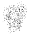
図1〜3は、本発明に係るハザード保持機能付ウインカ装置を搭載した自動2輪車を示す。自動2輪車10は、フレーム11と、フレーム11の前端部に有するヘッドパイプ12に取付けられたフロントフォーク13と、フロントフォーク13の上部に結合されたハンドル14と、フロントフォーク13の下部に取付けられた前輪15と、フレーム11の前下部に取付けられたエンジン17とトランスミッション18とからなるパワーユニット16と、フレーム11の後下部に取付けられたスイングアーム19と、スイングアーム19に取付けられた後輪20と、フレーム11の後部上部にシートレール21を介して取付けられたタンデムシート22と、から主として構成されており、パワーユニット16にて後輪20を駆動するようにした車輌である。
1 to 3 show a motorcycle equipped with a blinker device with a hazard retention function according to the present invention. The
また、自動2輪車10は、フレーム11の前部下方にラジエータ23を備え、フレーム11の前部及び両前側部を覆うフロントカウル50と、フレーム11の後部及び両後側部を覆うリアカウル60と、ラジエータ23を囲むラジエータカバー71を一体に有してフロントカウル50の内側に取付けられた左右のインナーカウル72,72と、を備える。フロントカウル50と、リアカウル60と、インナーカウル72,72とは、軽量なFRP等の合成樹脂を素材として成形される。
The
フレーム11は、例えばアルミニウム合金の鋳造により略U字形状に形成され後下方へ向けて左右一対で延びるメインフレーム24を有し、このメインフレーム24の前端部に円筒形状のヘッドハイプ12を有する。また、メインフレーム24の前端部に結合されヘッドパイプ12の後方に向けて後ろ下がりに延びるダウンチューブ25と、ヘッドパイプ12の前方に略L字形状に上方に向けて延出されたフロントブラケット26と、メインフレーム24の下方後端部に配置され後ろ上がりに延びるシートレール21の前端部が結合されたピボットプレート27と、を有する。
The
パワーユニット16は、エンジン17が水冷4ストロークOHC3バルブV型2気筒であってトランスミッション18を一体に内蔵しており、メインフレーム24とピボットプレート27とダウンチューブ25とによって支持されている。パワーユニット16の上部には、エアクリーナ(不図示)上にフューエルタンク28が取付けられている。エンジン17は、前気筒側シリンダヘッド17a及び後気筒側シリンダヘッド17bの吸気ポートにキャブレータ(不図示)が接続され、前気筒側シリンダヘッド17aの排気パイプ29及び後気筒側シリンダヘッド17bの排気パイプ30がエンジン17の下部で集合管31に接続され、集合管31からマフラー32に接続されている。トランスミッション18の出力は、側部に取り出されてからチェーン(不図示)を介して後輪20に固定されたスプロケット(不図示)に伝達される。
In the
フロントフォーク13には、コイルばねとダンパとからなるフロントサスペンション(不図示)が内蔵されているとともに、前輪15に固定された一対のディスクロータ33に制動力を与えるキャリパ34が組み付けられており、前輪15の上部を覆うフロントフェンダ35が取付けられている。
The
スイングアーム19は、ピボットプレート27によって揺動自在に支持されており、フレーム11との間に配置されたコイルばねとダンパとからなるリアサスペンション(不図示)によって緩衝される。後輪20には、前輪15と同様にしてディスクロータ35が取付けられている。
The
ラジエータ23は、前輪15の後方で、エンジン17の前気筒側シリンダヘッド17aの前方においてダウンチューブ25にボルト止めされており、インナーカウル72,72の下方に形成されたラジエータカバー71によって側部の周囲が覆われている。
The
フロントカウル50は、フロントセンターカウル51と、左,右アウターカウル52,52と、左、右ミドルカウル53,53と、から構成されている。
The
フロントセンターカウル51は、前面先端にヘッドライトユニット37が取付けられているとともに、ヘッドライトユニット37の下方にセンターエアインレット51aが設けられおり、センターエアインレット51aの両側に左右対称のサイドエアインレット51b,51bが設けられている。
The
フロントセンターカウル51は、左,右アウターカウル52,52の前方先端で両者に挟まれて配置され、フロントブラケット26にボルト止めされる。センターエアインレット51aは、前端部中央で前輪15の上方に配置されているために、走行中に正面から空気を導入してエアクリーナに空気を供給する。サイドエアインレット51b,51bは、前端部両側部で前輪15の上方に配置されているために、走行中に走行風の一部を導入して左,右ミドルカウル53,53方向に流す。
The
フロントセンターカウル51の上方には、ウインドスクリーン38が固定されており、フロントセンターカウル51の内側には、フロントブラケット26に固定されたメーターユニット(不図示)が配置されている。フロントセンターカウル51は、左,右アウターカウル52,52と組み合わされることで、走行中の走行風を前方から受けて前輪15にダウンフォースを与える。
A
左,右アウターカウル52,52は左右対称形状に形成されているために、ここでは左アウターカウル52についてのみ説明する。アウターカウル52は、ヘッドパイプ12の側部と、メインフレーム24の前方側部と、エンジン17の両シリンダヘッド17a,17bの側部と、を覆って配置されて、メインフレーム24とピボットプレート27とフロントブラケット26とにボルト止めされる。
Since the left and right
アウターカウル52には、上部に配置されたサイドウインカー用切欠52bと、ミドルカウル用切欠52cと、ミドルカウル53の下方に配置された突出部52dと、が設けられている。
The
サイドウインカ用切欠52bには、フロントブラケット26にボルト止めされた一対のサイドウインカ39が組み付けられる。
A pair of side turn signals 39 that are bolted to the
ミドルカウル用切欠52cには、メインフレーム24にボルト止めされたミドルカウル53が取付けられる。ミドルカウル53は、フロントセンターカウル51のサイドエアインレット51bを指向したスリット状の開口(不図示)を有するために、両サイドエアインレット51b,51bから導入された走行風を車体側面に沿って後方へ流す。
A
そして、突出部52dは、車体側面視逆三角形状にして、前方から後方に向けて翼形状に形成されて、ラジエータ23の後方側の位置で車体外側に向けて膨出する。この突出部52dは、上部を形成する上部面52eが略水平に配置され、下部前方を形成する下部面52fが後方下がりに配置されており、さらに、下部面52fの後方寄りにエアアウトレット52gを有する。
The
アウターカウル52の後方には、左右対称のサドルバッグ61aとリアフェンダー61bとを有するリアカウル60のサイドカウル61が連続して取付けられており、リアカウル60の後端上部に一対のリアコンビネーションランプ40が取付けられている。
Behind the
図3に示すように、右のハンドル14には、リザーバタンク80、ブレーキ用のレバー81、スイッチボックス82、及びハンドルグリップ83が設けられている。一方、左のハンドル14には、クラッチレバーホルダにクラッチレバー91が回動自在に支持され、スイッチボックス92、及びハンドルグリップ93が設けられている。
As shown in FIG. 3, the
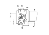
図4に示すように、スイッチボックス82は、前方へ押し倒すことでエンジンを停止するエンジン停止スイッチ(キルスイッチ)84と、押すことでスタータモータを回転させエンジンを始動するスタータスイッチ85と、左側へスライドすることで作動する後述のハザードスイッチ160とを備える。一方、図5に示すように、スイッチボックス92は、ヘッドライトユニット37の上下の向きを切り替えるディマースイッチ94と、押すことで警笛を鳴らすホーンスイッチ95、裏側に設置された不図示のパッシングスイッチ、及び後述するウインカスイッチ150等を備える。
As shown in FIG. 4, the
図7は、上記自動2輪車10に組み込まれる本実施形態に係るハザード保持機能付きウインカ装置の概略構成を示すブロック図である。同図において、ウインカ装置100は、前後左右に設けられたウインカ111〜114と、車両の電源であるバッテリ120と、キー操作によりバッテリ120から供給される電流をオン/オフするメインスイッチであるイグニッションスイッチ130と、ウインカ111〜114に対して点滅信号を出力するウインカリレー140と、ウインカリレー140の出力を左右いずれかのウインカ111,112又は113,114に選択して接続するウインカスイッチ150と、ウインカリレー140の出力を左右のウインカ111〜114に一括して接続するハザードスイッチ160と、ヒューズ171〜173を有して構成される。なお、左右のウインカ111〜114は、ハザードランプを兼用している。また、ウインカ111は自動2輪車10の左のサイドウインカ39に、ウインカ112は左のリアコンビネーションランプ40に、ウインカ113は右のサイドウインカ39に、ウインカ114は右のリアコンビネーションランプ40にそれぞれ配置される。
FIG. 7 is a block diagram showing a schematic configuration of the blinker device with a hazard holding function according to the present embodiment incorporated in the
図6に示すように、ウインカリレー140は、IGN端子、BAT端子、LOAD端子、及びEARTH端子を持ったカプラ141を備えると共に、側面には取付片142が形成されている。ウインカリレー140は、この取付片142をマウントゴム143の一方の貫通孔144に挿入し、他方の貫通孔145に図示しない車体側のステーを挿入することで、車体に固定される。
As shown in FIG. 6, the
図7に戻って、ウインカリレー140は、そのIGN端子がヒューズ171とイグニッションスイッチ130、及びメインヒューズ172を介してバッテリ120に接続され、BAT端子がヒューズ173及びメインヒューズ172を介してバッテリ120に常時接続されている。また、各ウインカ111〜114を点滅する電流を出力するLOAD端子が、ウインカスイッチ150の操作により動作する可動接点151に接続されるとともに、EARTH端子が接地されている。
Returning to FIG. 7, the
ウインカスイッチ150の左右の固定接点152、153には、それぞれ左右のウインカ111,112及び113,114が接続され、可動接点151が左右の固定接点152、153のいずれかに接触することにより、ウインカリレー140のLOAD端子と、左右のウインカ111,112及び113,114が選択的に接続される。
The left and
また、ウインカスイッチ150の可動接点151と左右の固定接点152、153の間には、常時開放のハザードスイッチ160が並列に接続され、可動接点161をオンにすることにより固定接点162〜164が短絡して、ウインカスイッチ150の可動接点151の位置にかかわらず、ウインカリレー140のLOAD端子と左右のウインカ111〜114が一括して接続される。
Also, a
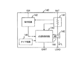
図8は、ウインカリレー140の概略構成を示すブロック図である。ウインカリレー140は、ICによって構成されており、BAT端子に接続され、各ウインカ111〜114に流れる電流を検出する電流検出回路141と、IGN端子に接続され、電流検出回路141で検出された電流に基づいてウインカ111〜114の点滅を保持する保持回路142と、ウインカ111〜114の点滅を制御する点滅制御回路143と、点滅制御回路143の出力に応じて励磁されるリレーコイル144と、リレーコイル144の励磁に応動して開閉し、LOAD端子を介してウインカ111〜114に点滅電流を出力するリレー接点145を有する構成である。
FIG. 8 is a block diagram showing a schematic configuration of the
なお、リレーコイル144とリレー接点145からなるリレーは、本実施形態のメカニカルリレーに限るものではなく、トランジスタ等からなる半導体リレーで構成することも可能である。
Note that the relay composed of the
上記構成のウインカリレー140において、BAT端子から供給され、電流検出回路141とリレー接点145を介してLOAD端子から出力される電流は、図7に示したウインカスイッチ150及びハザードスイッチ160の操作に対応するウインカ装置100の各機能に応じて変化する。表1は、ウインカ装置100の各機能を、電流検出回路141によって検出される電流値ILで判定する際の基準を示したものである。これには、各機能に対応するウインカの点滅速度及びメインスイッチをオフした際の制御を併せて示している。
In the

以下、本実施形態に係るウインカ装置の動作について、図7、図8及び表1を参照しながら説明する。 Hereinafter, the operation of the winker apparatus according to the present embodiment will be described with reference to FIGS.
まず、ウインカ装置100の左右折指示機能における動作について説明する。
車両にキーを挿入してイグニッションスイッチ130をオンにすると、電源120からメインヒューズ172及びヒューズ171を経てウインカリレー140に電源が供給される。車両の曲がる方向に応じてウインカスイッチ150を左右いずれかに倒すと、可動接点151が固定接点152又は153のいずれかと接触する。ウインカリレー140のLOAD端子からは、点滅制御回路143で生成され、リレー接点145でスイッチングされたウインカ点滅信号が出力され、左ウインカ111,112と右ウインカ113,114のいずれか一方に供給される。これにより、ウインカスイッチ150を倒した側のウインカ111,112又は113,114が点滅する。
ウインカスイッチ150は、内部で中立状態に戻るように付勢されており、ウインカスイッチ操作後、ウインカスイッチ150は接続状態を保持しつつ元の位置(中立)へ戻る。ウインカ操作後、ウインカスイッチ150を前方へ押し込むことでウインカが解除される。
First, the operation of the turn signal indicating function of the
When a key is inserted into the vehicle and the
The
このとき各ウインカ111〜114に流れる電流は、ウインカリレー140の電流検出回路141によって検出され、検出結果が保持回路142に送られて現在動作中のウインカ装置100の機能が判定される。現時点では、左ウインカ111、112と右ウインカ113,114の一方が点滅しているので、検出される電流値ILは、ウインカ1灯当たりに流れる電流をIBとしたとき、IL=2IBとなる。ここで表1を参照すると、ILは、1.5IB≦IL≦3IBの範囲にあるので、現在動作中のウインカ装置1の機能は左右折指示であると判定される。判定結果は点滅制御回路143に伝えられ、イグニッションスイッチ130をオフした際は、表1に示すように、点滅信号を停止する制御が行われる。
At this time, the current flowing through each of the
また、上記したウインカ装置100の左右折指示機能の動作中において、ウインカリレー140の電流検出回路141によって検出された電流値ILが、表1に示すIL<1.5IBである場合は、本来左右いずれかの点滅すべき2灯のウインカ111,112又は113,114のうち1灯が断線していることを示しているので、保持回路142はこの場合を断線警告と判定し、点滅制御回路143はこれを受けて点滅信号を通常の倍速になるよう制御する。これにより、残りのウインカ111〜114が通常の倍速で点滅し、車両の使用者はこれを見てウインカの断線を知ることができるので、速やかにウインカランプを交換することが可能となる。
Further, during the operation of the left right turn indicating function of the
次に、ウインカ装置100のハザード機能における動作について説明する。
イグニッションスイッチ130をオンにした状態でハザードスイッチ160をオンにすると、可動接点161を介して固定接点162〜164が短絡する。これにより、ウインカリレー140のLOAD端子と左右のウインカ111〜114が接続され、点滅制御回路143で生成されてリレー接点145でスイッチングされた点滅信号でウインカ111〜114のすべてが同時に点滅する。
Next, the operation in the hazard function of the
When the
このとき、各ウインカ111〜114に流れる電流は、ウインカリレー140の電流検出回路141によって検出され、検出結果が保持回路142に送られて現在動作中のウインカ装置100の機能が判定される。現時点では、すべてのウインカ111〜114が点滅しているので、検出される電流値ILは、IL=4IBとなる。表1によると、ILが、IL>3IBであれば、現在動作中のウインカ装置100の機能はハザードと判定される。判定結果は、点滅制御回路143に伝えられ、表1に示すように、イグニッションスイッチ130をオフした際にも、点滅信号を保持する制御が行われる。この状態は、ハザードスイッチ160をオフにするまで維持される。また、一旦ハザードスイッチ160をオフにすると、再びハザードスイッチ160をオンにしても、イグニッションスイッチ130がオフになっている限りウインカリレー140の各回路が動作しないので、LOAD端子から点滅信号が出力されることはない。
At this time, the current flowing through each of the
これにより、イグニッションスイッチ130をオンにした場合にのみハザード状態を開始できるとともに、ハザード状態のままキーを抜き取って車両から離れることが可能となる。
As a result, the hazard state can be started only when the
なお、ウインカリレー140は、図9に示すように、ハザード状態の保持中におけるハザードスイッチ160のオフ操作に同期してスタートし、所定の時間、例えば30秒又は1分を計測するタイマ回路146を設け、タイマが働いている間は、点滅制御回路143の動作を維持するようにしてもよい。これにより、ハザード状態の保持中に誤った操作を行ってハザードスイッチ160をオフにしても、タイマ動作中はLOAD端子から点滅信号が出力されているので、再度ハザードスイッチ160をオンにすることにより、メインスイッチをONにすることなくハザード状態に復帰させることができる。
As shown in FIG. 9, the
以上、説明したように、本実施形態に係る車両のハザード保持機能付きウインカ装置100によれば、左右のウインカ111〜114と、バッテリ120と、イグニッションスイッチ130と、ウインカ111〜114に点滅信号を出力するウインカリレー140と、ウインカリレー140の出力を左右いずれかのウインカ111,112又は113,114に選択して接続するウインカスイッチ150と、ウインカリレー140の出力を左右のウインカ111〜114に一括して接続するハザードスイッチ160と、を備えて構成する。そして、ウインカリレー140は、バッテリ120と常時接続され、所定の条件下、本実施形態では、ウインカ111〜114に流れる電流値がウインカ4灯分に相当する場合にハザード状態と判定して、イグニッションスイッチ130がオフされた後もウインカ111〜114を点滅するための電流を保持する。
As described above, according to the
これにより、イグニッションスイッチ130がオフの状態でもウインカリレー140が作動し、ハザード状態を保持させることができるので、ハザード保持機能のためのリレーを別途設ける必要がなく比較的簡単かつ安価な構成で、キーを抜き取って車両から離れてもハザード状態を保持することが可能となり、他人の悪戯によるウインカの点滅を防止することができる。
Thereby, even if the
また、ウインカリレー140は、ウインカ111〜114を点滅するための電流を検出する電流検出回路141を備え、ウインカリレー140は、電流検出回路141によって、ハザードスイッチ160をオンにした場合に相当する第1の所定電流を検出した際に、ウインカ111〜114を点滅するための電流を保持するので、ウインカリレー140は、ウインカ111〜114に流れる電流を検出することでハザード状態を判断し、イグニッションスイッチ130をオフした後もハザード状態を保持する。これにより、ハザード保持機能のためのリレーを別途設ける必要がなく、比較的簡単かつ安価なハザード保持機能付きウインカ装置100を構成することができる。
The
さらに、ウインカリレー140は、電流検出回路141によって、左右のウインカ111〜114のいずれかに断線がある場合に相当する第2の所定電流を検出した際に、ウインカ111〜114を倍速で点滅する電流を出力するので、電流検出回路141を兼用してウインカ111〜114の断線を検出して警告することができ、部品点数を増加することなく断線検出が可能となる。
Further, the
また、ウインカリレー140は、ウインカ111〜114を点滅するための電流を保持している状態で、ハザードスイッチ160をオフにした後は、ハザードスイッチ160を再度オンにしても、ウインカ111〜114を点滅させる電流を出力しないので、悪戯等による意図しないハザード機能の作動を防止することができる。
In addition, the
加えて、ウインカリレー140は、ウインカ111〜114を点滅するための電流を保持する時間を計測するタイマ回路146を備え、ウインカリレー140は、タイマ回路146によって計測した時間が所定の範囲内にある場合は、ハザードスイッチ160をオフにした後再度オンにすることにより、ウインカ111〜114を点滅させる電流を保持するので、ハザード状態を保持中に誤ってハザードスイッチ160をオフにした際に、短時間であればイグニッションスイッチ130を操作しなくてもハザード状態に容易に復帰させることができ、操作性が向上する。
In addition, the
また、ハザードスイッチ160は、ウインカスイッチ150に並列に接続されるので、既存のウインカ装置に簡単な配線を行うことによって、ハザード機能を追加することができる。
Further, since the
さらに、ウインカリレー140は、ICで構成されるので、部品点数の少ない、小型で軽量なウインカリレー140を構成することができる。
Further, since the
なお、本発明は前述した実施の形態に限定されるものではなく、適宜な変形、改良等が可能である。 Note that the present invention is not limited to the above-described embodiment, and appropriate modifications, improvements, and the like are possible.
10 自動2輪車(車両)
100 ウインカ装置
111〜114 ウインカ
120 バッテリ
130 メインスイッチ
140 ウインカリレー
141 電流検出回路
142 保持回路
143 点滅制御回路
144 リレー接点
146 タイマー回路
150 ウインカスイッチ
160 ハザードスイッチ
10 Motorcycle (vehicle)
DESCRIPTION OF
Claims (7)
前記ウインカリレーは、前記電源と常時接続され、且つ、所定の条件下で前記メインスイッチをオフした際に、前記ウインカを点滅するための電流を保持することを特徴とする車両のハザード保持機能付きウインカ装置。 A main switch for turning on / off the vehicle by key operation, a winker relay for outputting a current for blinking the left and right turn signals of the vehicle when the main switch is turned on, and an output of the turn signal relay A winker device with a hazard holding function for a vehicle, comprising: a winker switch that is selectively connected to either the left or right winker; and a hazard switch that collectively connects the output of the winker relay to the left and right winkers,
The winker relay is always connected to the power source, and holds a current for blinking the winker when the main switch is turned off under a predetermined condition. Turn signal equipment.
前記ウインカリレーは、該電流検出部によって、前記ハザードスイッチをオンにした場合に相当する第1の所定電流を検出した際に、前記ウインカを点滅するための電流を保持することを特徴とする請求項1に記載の車両のハザード保持機能付きウインカ装置。 The winker relay includes a current detection unit that detects a current for blinking the winker,
The winker relay holds a current for blinking the winker when the current detecting unit detects a first predetermined current corresponding to a case where the hazard switch is turned on. Item 10. A blinker device with a hazard holding function for a vehicle according to Item 1.
前記ウインカリレーは、該タイマ部によって計測した時間が所定の範囲内にある場合は、前記ハザードスイッチをオフにした後再度オンにすることにより、前記ウインカを点滅させる電流を保持することを特徴とする請求項2に記載の車両のハザード保持機能付きウインカ装置。 The winker relay includes a timer unit for measuring a time for holding a current for blinking the winker,
When the time measured by the timer unit is within a predetermined range, the winker relay holds a current for blinking the winker by turning the hazard switch off and then on again. The turn signal device with a hazard holding function for a vehicle according to claim 2.
Priority Applications (10)
| Application Number | Priority Date | Filing Date | Title |
|---|---|---|---|
| JP2005317757A JP4397877B2 (en) | 2005-10-31 | 2005-10-31 | Blinker device with vehicle hazard retention function |
| EP06019614A EP1780081B1 (en) | 2005-10-31 | 2006-09-19 | Winker unit for vehicle with hazard maintaining function |
| DE602006005303T DE602006005303D1 (en) | 2005-10-31 | 2006-09-19 | Vehicle turn signal unit with maintenance of the hazard warning function |
| ES06019614T ES2322869T3 (en) | 2005-10-31 | 2006-09-19 | FLASHING UNIT FOR A VEHICLE WITH A DANGER INDICATION MAINTENANCE FUNCTION. |
| TW095137842A TW200730378A (en) | 2005-10-31 | 2006-10-14 | Winker unit for vehicle with alert maintaining function |
| KR1020060101380A KR100796474B1 (en) | 2005-10-31 | 2006-10-18 | Winker device having a hazard maintenance function |
| MXPA06012354A MXPA06012354A (en) | 2005-10-31 | 2006-10-26 | Winker unit for vehicle with hazard maintaining function. |
| CN2006101427071A CN1958338B (en) | 2005-10-31 | 2006-10-26 | Winker unit for vehicle with hazard maintaining function |
| US11/586,660 US7586406B2 (en) | 2005-10-31 | 2006-10-26 | Winker unit for vehicle with hazard maintaining function |
| BRPI0604368A BRPI0604368B1 (en) | 2005-10-31 | 2006-10-27 | vehicle turn signal unit with alert maintenance function |
Applications Claiming Priority (1)
| Application Number | Priority Date | Filing Date | Title |
|---|---|---|---|
| JP2005317757A JP4397877B2 (en) | 2005-10-31 | 2005-10-31 | Blinker device with vehicle hazard retention function |
Publications (2)
| Publication Number | Publication Date |
|---|---|
| JP2007125901A true JP2007125901A (en) | 2007-05-24 |
| JP4397877B2 JP4397877B2 (en) | 2010-01-13 |
Family
ID=37307435
Family Applications (1)
| Application Number | Title | Priority Date | Filing Date |
|---|---|---|---|
| JP2005317757A Active JP4397877B2 (en) | 2005-10-31 | 2005-10-31 | Blinker device with vehicle hazard retention function |
Country Status (10)
| Country | Link |
|---|---|
| US (1) | US7586406B2 (en) |
| EP (1) | EP1780081B1 (en) |
| JP (1) | JP4397877B2 (en) |
| KR (1) | KR100796474B1 (en) |
| CN (1) | CN1958338B (en) |
| BR (1) | BRPI0604368B1 (en) |
| DE (1) | DE602006005303D1 (en) |
| ES (1) | ES2322869T3 (en) |
| MX (1) | MXPA06012354A (en) |
| TW (1) | TW200730378A (en) |
Cited By (5)
| Publication number | Priority date | Publication date | Assignee | Title |
|---|---|---|---|---|
| JP2010042756A (en) * | 2008-08-12 | 2010-02-25 | Honda Motor Co Ltd | Motorcycle |
| WO2012132830A1 (en) * | 2011-03-31 | 2012-10-04 | 本田技研工業株式会社 | Vehicle lighting control system |
| JP2013199186A (en) * | 2012-03-23 | 2013-10-03 | Mitsuba Corp | Lamp body controller |
| US8936123B2 (en) | 2008-08-08 | 2015-01-20 | Honda Motor Co., Ltd. | Vehicle |
| WO2016113857A1 (en) | 2015-01-14 | 2016-07-21 | 新電元工業株式会社 | Turn-signal system and turn-signal device |
Families Citing this family (12)
| Publication number | Priority date | Publication date | Assignee | Title |
|---|---|---|---|---|
| JP4584781B2 (en) * | 2005-06-15 | 2010-11-24 | 本田技研工業株式会社 | Cowling structure for motorcycles |
| US8482398B2 (en) | 2010-10-14 | 2013-07-09 | Custom Dynamics Llc | Electronic control circuit for lamps of a vehicle |
| CN103358984B (en) * | 2012-03-27 | 2016-03-30 | 武汉恒诺汽车零部件有限公司 | Steering indicating light Warning light intelligent control method |
| WO2014024246A1 (en) * | 2012-08-06 | 2014-02-13 | 新電元工業株式会社 | Direction-indication device |
| WO2014024245A1 (en) * | 2012-08-06 | 2014-02-13 | 新電元工業株式会社 | Direction-indication device |
| CN105377681A (en) * | 2013-11-15 | 2016-03-02 | 川崎重工业株式会社 | Motorcycle |
| JP6413172B2 (en) * | 2014-01-10 | 2018-10-31 | 矢崎総業株式会社 | Disconnection detector |
| JP6423154B2 (en) * | 2014-01-17 | 2018-11-14 | 矢崎総業株式会社 | Disconnection detector |
| CN105644432B (en) * | 2016-03-25 | 2018-05-29 | 盐城市步高汽配制造有限公司 | A kind of automobile with urgent warning lamp |
| US10436315B2 (en) * | 2017-06-29 | 2019-10-08 | GM Global Technology Operations LLC | Systems and methods for controlling an engine and hazard lights based on start/stop switch actuation |
| CA3123209C (en) * | 2018-12-11 | 2022-08-30 | Ess-Help, Inc. | Enhancement of vehicle hazard systems |
| DE102023003007A1 (en) | 2023-07-24 | 2023-11-23 | Mercedes-Benz Group AG | Switch module and its use |
Family Cites Families (9)
| Publication number | Priority date | Publication date | Assignee | Title |
|---|---|---|---|---|
| JPS599377B2 (en) | 1976-01-09 | 1984-03-02 | スズキ株式会社 | Hazard awning device for motorcycles, etc. |
| US4380753A (en) * | 1979-11-19 | 1983-04-19 | Gant Leroy A | Turn signal and hazard signal control circuit |
| DE4113455C2 (en) * | 1991-04-25 | 1994-02-10 | Telefunken Microelectron | Electronic flasher |
| JP3523926B2 (en) * | 1994-12-29 | 2004-04-26 | 本田技研工業株式会社 | Hazard device for motorcycle |
| KR970069577A (en) * | 1996-04-18 | 1997-11-07 | 스즈키 다케토시 | Electronic Flasher |
| US5805061A (en) * | 1997-04-08 | 1998-09-08 | Hella Kg Hueck & Co. | Electronic flasher unit for vehicle lighting system and method of monitoring the operation thereof |
| JPH11263164A (en) * | 1998-03-17 | 1999-09-28 | Mitsuba Corp | Flashing device for vehicle |
| DE19854051C2 (en) * | 1998-11-24 | 2001-05-23 | Temic Semiconductor Gmbh | Method and circuit arrangement for comparing an input signal with different voltage thresholds in an electronic flasher unit |
| JP3979270B2 (en) * | 2002-11-15 | 2007-09-19 | アンデン株式会社 | Vehicle direction indicating device and flasher circuit used therefor |
-
2005
- 2005-10-31 JP JP2005317757A patent/JP4397877B2/en active Active
-
2006
- 2006-09-19 ES ES06019614T patent/ES2322869T3/en active Active
- 2006-09-19 EP EP06019614A patent/EP1780081B1/en active Active
- 2006-09-19 DE DE602006005303T patent/DE602006005303D1/en active Active
- 2006-10-14 TW TW095137842A patent/TW200730378A/en not_active IP Right Cessation
- 2006-10-18 KR KR1020060101380A patent/KR100796474B1/en not_active IP Right Cessation
- 2006-10-26 US US11/586,660 patent/US7586406B2/en active Active
- 2006-10-26 MX MXPA06012354A patent/MXPA06012354A/en active IP Right Grant
- 2006-10-26 CN CN2006101427071A patent/CN1958338B/en active Active
- 2006-10-27 BR BRPI0604368A patent/BRPI0604368B1/en active IP Right Grant
Cited By (9)
| Publication number | Priority date | Publication date | Assignee | Title |
|---|---|---|---|---|
| US8936123B2 (en) | 2008-08-08 | 2015-01-20 | Honda Motor Co., Ltd. | Vehicle |
| JP2010042756A (en) * | 2008-08-12 | 2010-02-25 | Honda Motor Co Ltd | Motorcycle |
| WO2012132830A1 (en) * | 2011-03-31 | 2012-10-04 | 本田技研工業株式会社 | Vehicle lighting control system |
| JP5577457B2 (en) * | 2011-03-31 | 2014-08-20 | 本田技研工業株式会社 | Vehicle lighting control system |
| US9216686B2 (en) | 2011-03-31 | 2015-12-22 | Honda Motor Co., Ltd. | Vehicle lighting control system |
| JP2013199186A (en) * | 2012-03-23 | 2013-10-03 | Mitsuba Corp | Lamp body controller |
| WO2016113857A1 (en) | 2015-01-14 | 2016-07-21 | 新電元工業株式会社 | Turn-signal system and turn-signal device |
| JP5960364B1 (en) * | 2015-01-14 | 2016-08-02 | 新電元工業株式会社 | Direction indication system and direction indication device |
| US9682650B2 (en) | 2015-01-14 | 2017-06-20 | Shindengen Electric Manufacturing Co., Ltd. | Direction indicator system and direction indicator device for a vehicle |
Also Published As
| Publication number | Publication date |
|---|---|
| JP4397877B2 (en) | 2010-01-13 |
| US7586406B2 (en) | 2009-09-08 |
| KR100796474B1 (en) | 2008-01-21 |
| TWI301811B (en) | 2008-10-11 |
| ES2322869T3 (en) | 2009-06-30 |
| TW200730378A (en) | 2007-08-16 |
| CN1958338B (en) | 2011-02-02 |
| KR20070046716A (en) | 2007-05-03 |
| BRPI0604368B1 (en) | 2017-02-07 |
| BRPI0604368A (en) | 2007-08-28 |
| CN1958338A (en) | 2007-05-09 |
| US20070096893A1 (en) | 2007-05-03 |
| DE602006005303D1 (en) | 2009-04-09 |
| MXPA06012354A (en) | 2007-07-04 |
| EP1780081B1 (en) | 2009-02-25 |
| EP1780081A1 (en) | 2007-05-02 |
Similar Documents
| Publication | Publication Date | Title |
|---|---|---|
| JP4397877B2 (en) | Blinker device with vehicle hazard retention function | |
| US11767074B2 (en) | Two-wheeled vehicle | |
| TWI260292B (en) | Storage device for motorcycle | |
| JP4176610B2 (en) | Scooter type vehicle | |
| JP4630780B2 (en) | Arrangement structure of scooter type vehicles | |
| JP2012076524A (en) | Vehicle approach notification control apparatus for electric motorcycle | |
| JP2005112312A (en) | Motorcycle | |
| JP2016078497A (en) | Saddle riding type vehicle | |
| JP4119344B2 (en) | Motorcycle | |
| JP5289883B2 (en) | Saddle riding vehicle | |
| JP5750020B2 (en) | Motorcycle | |
| CN102442266A (en) | Vehicle approach notification apparatus for electric motorcycle | |
| JP4853913B2 (en) | Motorcycle headlamp device | |
| JP2014108650A (en) | Vehicle body front structure of saddle-riding type vehicle | |
| JP5806483B2 (en) | Vehicle with cowl | |
| JP3901096B2 (en) | Body frame structure of motorcycle | |
| JP5591785B2 (en) | Light fixture assembly for saddle-ride type vehicles | |
| JP4145620B2 (en) | Small vehicle | |
| WO2018225427A1 (en) | Tilting vehicle | |
| KR950009637Y1 (en) | Arrangement of lighting device on bicycls | |
| JP2003089371A (en) | Light-emission device for vehicle | |
| JPH08258618A (en) | Headlight lighting control device of motorcycle | |
| JP2005139912A (en) | Automatic idling stop vehicle | |
| JP4681017B2 (en) | Scooter type motorcycle | |
| JP2020200036A (en) | Handle switch of motor cycle |
Legal Events
| Date | Code | Title | Description |
|---|---|---|---|
| A621 | Written request for application examination |
Free format text: JAPANESE INTERMEDIATE CODE: A621 Effective date: 20071127 |
|
| RD04 | Notification of resignation of power of attorney |
Free format text: JAPANESE INTERMEDIATE CODE: A7424 Effective date: 20071129 |
|
| A977 | Report on retrieval |
Free format text: JAPANESE INTERMEDIATE CODE: A971007 Effective date: 20090708 |
|
| A131 | Notification of reasons for refusal |
Free format text: JAPANESE INTERMEDIATE CODE: A131 Effective date: 20090714 |
|
| A521 | Written amendment |
Free format text: JAPANESE INTERMEDIATE CODE: A523 Effective date: 20090902 |
|
| RD03 | Notification of appointment of power of attorney |
Free format text: JAPANESE INTERMEDIATE CODE: A7423 Effective date: 20090902 |
|
| RD04 | Notification of resignation of power of attorney |
Free format text: JAPANESE INTERMEDIATE CODE: A7424 Effective date: 20090903 |
|
| TRDD | Decision of grant or rejection written | ||
| A01 | Written decision to grant a patent or to grant a registration (utility model) |
Free format text: JAPANESE INTERMEDIATE CODE: A01 Effective date: 20091014 |
|
| A01 | Written decision to grant a patent or to grant a registration (utility model) |
Free format text: JAPANESE INTERMEDIATE CODE: A01 |
|
| A61 | First payment of annual fees (during grant procedure) |
Free format text: JAPANESE INTERMEDIATE CODE: A61 Effective date: 20091021 |
|
| FPAY | Renewal fee payment (event date is renewal date of database) |
Free format text: PAYMENT UNTIL: 20121030 Year of fee payment: 3 |
|
| R150 | Certificate of patent or registration of utility model |
Ref document number: 4397877 Country of ref document: JP Free format text: JAPANESE INTERMEDIATE CODE: R150 Free format text: JAPANESE INTERMEDIATE CODE: R150 |
|
| FPAY | Renewal fee payment (event date is renewal date of database) |
Free format text: PAYMENT UNTIL: 20121030 Year of fee payment: 3 |
|
| FPAY | Renewal fee payment (event date is renewal date of database) |
Free format text: PAYMENT UNTIL: 20131030 Year of fee payment: 4 |
|
| R250 | Receipt of annual fees |
Free format text: JAPANESE INTERMEDIATE CODE: R250 |