JP2007123722A - シールド構造 - Google Patents
シールド構造 Download PDFInfo
- Publication number
- JP2007123722A JP2007123722A JP2005316797A JP2005316797A JP2007123722A JP 2007123722 A JP2007123722 A JP 2007123722A JP 2005316797 A JP2005316797 A JP 2005316797A JP 2005316797 A JP2005316797 A JP 2005316797A JP 2007123722 A JP2007123722 A JP 2007123722A
- Authority
- JP
- Japan
- Prior art keywords
- circuit board
- shield case
- cut
- housing
- shield
- Prior art date
- Legal status (The legal status is an assumption and is not a legal conclusion. Google has not performed a legal analysis and makes no representation as to the accuracy of the status listed.)
- Granted
Links
- 239000004020 conductor Substances 0.000 claims abstract description 32
- 230000015572 biosynthetic process Effects 0.000 claims abstract description 3
- 238000005452 bending Methods 0.000 abstract description 5
- 239000000463 material Substances 0.000 description 5
- 239000011347 resin Substances 0.000 description 5
- 229920005989 resin Polymers 0.000 description 5
- 230000000694 effects Effects 0.000 description 4
- 239000011810 insulating material Substances 0.000 description 4
- 239000000758 substrate Substances 0.000 description 3
- 230000002411 adverse Effects 0.000 description 2
- 206010067482 No adverse event Diseases 0.000 description 1
- 239000003990 capacitor Substances 0.000 description 1
- 238000010586 diagram Methods 0.000 description 1
- 239000010410 layer Substances 0.000 description 1
- 238000000034 method Methods 0.000 description 1
- 230000002093 peripheral effect Effects 0.000 description 1
- 229910000679 solder Inorganic materials 0.000 description 1
- 230000000087 stabilizing effect Effects 0.000 description 1
- 239000002344 surface layer Substances 0.000 description 1
Images
Landscapes
- Shielding Devices Or Components To Electric Or Magnetic Fields (AREA)
Abstract
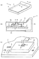
【解決手段】電気回路が形成されている回路基板2には、その基板面の一部を覆い回路基板2のグランドに接地されて電気回路の一部をシールドするシールドケース5を設ける。回路基板2を収容する筐体3は、少なくともシールドケース5が配設されている回路基板2の基板面に面している筐体部分3aの内壁面が導体により形成されている構成を有する。シールドケース5の天面部には、複数の切り起こし片6を、共通の開口部7を囲んで起立配置される態様でもって切り起こし形成する。全ての切り起こし片6は、それぞれ、導体から成る筐体部分3aの内壁面に押圧接触している。筐体部分3aの内壁面は、切り起こし片6との押圧接触部と、シールドケース5とを介して回路基板2のグランドに接地されて回路基板をシールドしている。
【選択図】図1
Description
電気回路が形成されている回路基板と、
回路基板の基板面の一部を覆う態様で回路基板に配設され回路基板に設けられているグランドに接地されて電気回路の一部をシールドするシールドケースと、
前記回路基板を収容する筐体と、
を有し、
筐体は、少なくともシールドケースが配設されている回路基板の基板面に面している筐体内壁面部分が導体により構成されており、
シールドケースの天面部には、複数の切り起こし片が共通の開口部を囲んで起立配置される態様でもって切り起こし形成され、全ての切り起こし片は、それぞれ、前記導体から成る筐体内壁面部分に押圧接触しており、
前記導体から成る筐体内壁面部分は、切り起こし片との押圧接触部と、シールドケースとを介して回路基板のグランドに接地されて回路基板をシールドしていることを特徴としている。
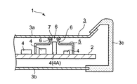
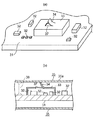
3 筐体
4 電気部品
5 シールドケース
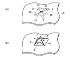
6 切り起こし片
7 開口部
Claims (2)
- 電気回路が形成されている回路基板と、
回路基板の基板面の一部を覆う態様で回路基板に配設され回路基板に設けられているグランドに接地されて電気回路の一部をシールドするシールドケースと、
前記回路基板を収容する筐体と、
を有し、
筐体は、少なくともシールドケースが配設されている回路基板の基板面に面している筐体内壁面部分が導体により構成されており、
シールドケースの天面部には、複数の切り起こし片が共通の開口部を囲んで起立配置される態様でもって切り起こし形成され、全ての切り起こし片は、それぞれ、前記導体から成る筐体内壁面部分に押圧接触しており、
前記導体から成る筐体内壁面部分は、切り起こし片との押圧接触部と、シールドケースとを介して回路基板のグランドに接地されて回路基板をシールドしていることを特徴とするシールド構造。 - シールドケースの開口部の形成領域に面する回路基板面部分には、前記開口部から複数の切り起こし片により囲まれている空間部に突き出る背高な部品が配置されていることを特徴とする請求項1記載のシールド構造。
Priority Applications (1)
| Application Number | Priority Date | Filing Date | Title |
|---|---|---|---|
| JP2005316797A JP4674527B2 (ja) | 2005-10-31 | 2005-10-31 | シールド構造 |
Applications Claiming Priority (1)
| Application Number | Priority Date | Filing Date | Title |
|---|---|---|---|
| JP2005316797A JP4674527B2 (ja) | 2005-10-31 | 2005-10-31 | シールド構造 |
Publications (2)
| Publication Number | Publication Date |
|---|---|
| JP2007123722A true JP2007123722A (ja) | 2007-05-17 |
| JP4674527B2 JP4674527B2 (ja) | 2011-04-20 |
Family
ID=38147206
Family Applications (1)
| Application Number | Title | Priority Date | Filing Date |
|---|---|---|---|
| JP2005316797A Expired - Fee Related JP4674527B2 (ja) | 2005-10-31 | 2005-10-31 | シールド構造 |
Country Status (1)
| Country | Link |
|---|---|
| JP (1) | JP4674527B2 (ja) |
Cited By (6)
| Publication number | Priority date | Publication date | Assignee | Title |
|---|---|---|---|---|
| JP2011077446A (ja) * | 2009-10-01 | 2011-04-14 | Sanyo Electric Co Ltd | シールドケース及び画像表示装置 |
| JP2011209683A (ja) * | 2010-03-12 | 2011-10-20 | Sumitomo Electric Device Innovations Inc | 光トランシーバ |
| JP5233677B2 (ja) * | 2007-01-29 | 2013-07-10 | 日本電気株式会社 | 電子機器のシールド構造、シールド部材及びこれを備える電子機器 |
| JP2015005751A (ja) * | 2013-06-19 | 2015-01-08 | ケースレー・インスツルメンツ・インコーポレイテッドKeithley Instruments,Inc. | 印刷回路基板アイランド及びその設置方法 |
| US20230301045A1 (en) * | 2022-03-15 | 2023-09-21 | Chukwubuikem Marcel Okoli | Eyewear with rf shielding having grounding springs |
| CN117242910A (zh) * | 2021-05-19 | 2023-12-15 | 日立安斯泰莫株式会社 | 电子控制装置 |
Citations (8)
| Publication number | Priority date | Publication date | Assignee | Title |
|---|---|---|---|---|
| JPS63153599U (ja) * | 1987-03-30 | 1988-10-07 | ||
| JPH0325295U (ja) * | 1989-07-21 | 1991-03-15 | ||
| JPH0338698U (ja) * | 1989-08-26 | 1991-04-15 | ||
| JPH03101593U (ja) * | 1990-02-05 | 1991-10-23 | ||
| JP2000286584A (ja) * | 1999-03-30 | 2000-10-13 | Kokusai Electric Co Ltd | 携帯型通信機のシールド構造 |
| JP2001223526A (ja) * | 2000-02-07 | 2001-08-17 | Alps Electric Co Ltd | 電圧制御発振器 |
| JP2001284875A (ja) * | 2000-03-31 | 2001-10-12 | Matsushita Electric Ind Co Ltd | 筺体の不要輻射電磁波遮蔽構造および導電性筺体構成要素 |
| JP2002190690A (ja) * | 2000-12-22 | 2002-07-05 | Murata Mfg Co Ltd | 電子部品モジュール |
-
2005
- 2005-10-31 JP JP2005316797A patent/JP4674527B2/ja not_active Expired - Fee Related
Patent Citations (8)
| Publication number | Priority date | Publication date | Assignee | Title |
|---|---|---|---|---|
| JPS63153599U (ja) * | 1987-03-30 | 1988-10-07 | ||
| JPH0325295U (ja) * | 1989-07-21 | 1991-03-15 | ||
| JPH0338698U (ja) * | 1989-08-26 | 1991-04-15 | ||
| JPH03101593U (ja) * | 1990-02-05 | 1991-10-23 | ||
| JP2000286584A (ja) * | 1999-03-30 | 2000-10-13 | Kokusai Electric Co Ltd | 携帯型通信機のシールド構造 |
| JP2001223526A (ja) * | 2000-02-07 | 2001-08-17 | Alps Electric Co Ltd | 電圧制御発振器 |
| JP2001284875A (ja) * | 2000-03-31 | 2001-10-12 | Matsushita Electric Ind Co Ltd | 筺体の不要輻射電磁波遮蔽構造および導電性筺体構成要素 |
| JP2002190690A (ja) * | 2000-12-22 | 2002-07-05 | Murata Mfg Co Ltd | 電子部品モジュール |
Cited By (8)
| Publication number | Priority date | Publication date | Assignee | Title |
|---|---|---|---|---|
| JP5233677B2 (ja) * | 2007-01-29 | 2013-07-10 | 日本電気株式会社 | 電子機器のシールド構造、シールド部材及びこれを備える電子機器 |
| JP2011077446A (ja) * | 2009-10-01 | 2011-04-14 | Sanyo Electric Co Ltd | シールドケース及び画像表示装置 |
| JP2011209683A (ja) * | 2010-03-12 | 2011-10-20 | Sumitomo Electric Device Innovations Inc | 光トランシーバ |
| JP2015005751A (ja) * | 2013-06-19 | 2015-01-08 | ケースレー・インスツルメンツ・インコーポレイテッドKeithley Instruments,Inc. | 印刷回路基板アイランド及びその設置方法 |
| CN117242910A (zh) * | 2021-05-19 | 2023-12-15 | 日立安斯泰莫株式会社 | 电子控制装置 |
| US20230301045A1 (en) * | 2022-03-15 | 2023-09-21 | Chukwubuikem Marcel Okoli | Eyewear with rf shielding having grounding springs |
| US12010825B2 (en) * | 2022-03-15 | 2024-06-11 | Snap Inc. | Eyewear with RF shielding having grounding springs |
| US12342516B2 (en) | 2022-03-15 | 2025-06-24 | Snap Inc. | Eyewear with RF shielding having grounding springs |
Also Published As
| Publication number | Publication date |
|---|---|
| JP4674527B2 (ja) | 2011-04-20 |
Similar Documents
| Publication | Publication Date | Title |
|---|---|---|
| US8558121B2 (en) | Electronic device having an electromagnetic shield | |
| KR100708056B1 (ko) | 전자기 차폐판, 전자기 차폐 구조체 및 엔터테인먼트 장치 | |
| JP5233677B2 (ja) | 電子機器のシールド構造、シールド部材及びこれを備える電子機器 | |
| JP4304118B2 (ja) | マイクロホンの出力コネクタ | |
| US7663895B2 (en) | Electromagnetic shielding device for printed circuit board | |
| JP2005005866A (ja) | アンテナ一体型モジュール | |
| JP2008060358A (ja) | 電子機器 | |
| US20060189183A1 (en) | Camera module connector | |
| US20090268420A1 (en) | Shielding assembly | |
| JP4348725B2 (ja) | 電子部品取付用ソケット | |
| JP2005094575A (ja) | マイクロホンの出力コネクタ | |
| US9190779B2 (en) | Electrical connector having better electrical performance | |
| JP4674527B2 (ja) | シールド構造 | |
| US6469912B1 (en) | Electrical apparatus having a cover member adapted to provide electromagnetic interference shielding to an electronic component | |
| JP2006165201A (ja) | 回路モジュール装置 | |
| JP2009141057A (ja) | 電子機器及びスロット | |
| TW200922439A (en) | Electronic circuit mould | |
| CN107018645A (zh) | 屏蔽结构、屏蔽结构制作方法、电路模组与移动电子终端 | |
| JP2013149411A (ja) | 電気コネクタ | |
| JP3028956B1 (ja) | 環境配慮型fg構造 | |
| JP3094771B2 (ja) | 電子・通信装置ユニット構造 | |
| JP5206097B2 (ja) | 電子機器および接地機構 | |
| JP3892189B2 (ja) | 電子回路基板の電磁波遮蔽構造 | |
| JP2011228697A (ja) | シールドケース及びこのシールドケースを有する電子装置 | |
| CN206923232U (zh) | 屏蔽结构、电路模组与移动电子终端 |
Legal Events
| Date | Code | Title | Description |
|---|---|---|---|
| A621 | Written request for application examination |
Free format text: JAPANESE INTERMEDIATE CODE: A621 Effective date: 20080909 |
|
| A977 | Report on retrieval |
Free format text: JAPANESE INTERMEDIATE CODE: A971007 Effective date: 20101022 |
|
| A131 | Notification of reasons for refusal |
Free format text: JAPANESE INTERMEDIATE CODE: A131 Effective date: 20101102 |
|
| A521 | Written amendment |
Free format text: JAPANESE INTERMEDIATE CODE: A523 Effective date: 20101201 |
|
| TRDD | Decision of grant or rejection written | ||
| A01 | Written decision to grant a patent or to grant a registration (utility model) |
Free format text: JAPANESE INTERMEDIATE CODE: A01 Effective date: 20101228 |
|
| A01 | Written decision to grant a patent or to grant a registration (utility model) |
Free format text: JAPANESE INTERMEDIATE CODE: A01 |
|
| A61 | First payment of annual fees (during grant procedure) |
Free format text: JAPANESE INTERMEDIATE CODE: A61 Effective date: 20110110 |
|
| FPAY | Renewal fee payment (event date is renewal date of database) |
Free format text: PAYMENT UNTIL: 20140204 Year of fee payment: 3 |
|
| R150 | Certificate of patent or registration of utility model |
Ref document number: 4674527 Country of ref document: JP Free format text: JAPANESE INTERMEDIATE CODE: R150 Free format text: JAPANESE INTERMEDIATE CODE: R150 |
|
| LAPS | Cancellation because of no payment of annual fees |