JP2007105657A - Gas treatment apparatus - Google Patents
Gas treatment apparatus Download PDFInfo
- Publication number
- JP2007105657A JP2007105657A JP2005300033A JP2005300033A JP2007105657A JP 2007105657 A JP2007105657 A JP 2007105657A JP 2005300033 A JP2005300033 A JP 2005300033A JP 2005300033 A JP2005300033 A JP 2005300033A JP 2007105657 A JP2007105657 A JP 2007105657A
- Authority
- JP
- Japan
- Prior art keywords
- gas
- adsorption
- adsorbent
- desorption
- processing apparatus
- Prior art date
- Legal status (The legal status is an assumption and is not a legal conclusion. Google has not performed a legal analysis and makes no representation as to the accuracy of the status listed.)
- Pending
Links
Images


Abstract
Description
本発明は、排ガス中に含まれる有機溶剤などの有害物質を除去するガス処理装置に関する。特に、大気汚染の原因物質である揮発性有機化合物(VOC)を含む排ガスを放出する発生源から発生した排ガスからVOCを除去する装置に関する。 The present invention relates to a gas processing apparatus for removing harmful substances such as organic solvents contained in exhaust gas. In particular, the present invention relates to an apparatus for removing VOC from exhaust gas generated from a source that emits exhaust gas containing a volatile organic compound (VOC) that is a cause of air pollution.
従来、この種のガス処理装置は、発生源に設置した局所排気装置のエンドオブパイプで処理する方式が用いられる。 Conventionally, this type of gas processing apparatus employs a method of processing with an end-of-pipe of a local exhaust apparatus installed at a generation source.
この方式は、局所排気により周囲の空気も同時に吸引するため比較的低濃度の排ガスを処理する必要があり、活性炭やゼオライトなどの吸着剤による吸着・濃縮と濃縮後のガスを処理する方式が用いられることが多い。処理方式としては、冷却凝縮による液化回収、燃焼・触媒燃焼による分解などがある。 In this method, ambient air is simultaneously sucked in by local exhaust, so it is necessary to treat exhaust gas with a relatively low concentration. Adsorption / concentration with an adsorbent such as activated carbon and zeolite, and a method of treating the gas after concentration are used. It is often done. Treatment methods include liquefaction recovery by cooling condensation and decomposition by combustion / catalytic combustion.
例えば、有機溶剤ガスを活性炭やゼオライトなどの吸着剤で吸着し、吸着後の実質的に有機溶剤を含まないガスを大気放出し、吸着剤が有機溶剤で飽和すると熱や圧力を用い脱着再生し、脱着した有機溶剤の濃縮ガスを冷却し液化して回収するものが知られている
(例えば、特許文献1)。
For example, an organic solvent gas is adsorbed with an adsorbent such as activated carbon or zeolite, and the gas substantially free of organic solvent after adsorption is released to the atmosphere. When the adsorbent is saturated with an organic solvent, it is desorbed and regenerated using heat and pressure. In addition, there is known a method in which a concentrated gas of a desorbed organic solvent is cooled, liquefied and recovered (for example, Patent Document 1).
以下、その排ガス処理装置について図9を参照しながら説明する。 Hereinafter, the exhaust gas treatment apparatus will be described with reference to FIG.
図に示すように、従来の排ガス処理装置101は、有機溶剤ガスを吸着する吸着手段102と吸着した有機溶剤ガスを脱着する脱着手段103と脱着した有機溶剤ガスを液化する液化手段104で構成している。吸着手段102は、活性炭、ゼオライトなどの吸着剤を備え、排ガス中の有機溶剤を吸着除去する。吸着剤の破過を予測または検知して、脱着手段103によって有機溶剤を脱着し吸着剤を再生する。ここで、脱着手段103は、真空ポンプが用いられ、減圧することによって有機溶剤を脱着する。
As shown in the figure, a conventional exhaust
脱着した有機溶剤ガスは、液化手段104に送られ、冷却し液化する。液化手段104を通った未凝縮のガスはそのまま、排気されるか、吸着剤に再び戻される。
このような排ガス処理装置では、吸着剤の使用量を少なくし、また、液化、燃焼などの処理手段を小型化して、装置を小型化するとともに、排気ガス中の有機溶剤ガスを確実に除去し、例えば排出ガスの濃度規制値以下の濃度することが要求されている。 In such an exhaust gas treatment device, the amount of adsorbent used is reduced, the treatment means such as liquefaction and combustion are miniaturized, the device is miniaturized, and the organic solvent gas in the exhaust gas is reliably removed. For example, the concentration is required to be equal to or lower than the concentration regulation value of the exhaust gas.
しかしながら、従来のガス処理装置では局所排気装置の風量に対応するため吸着濃縮のための吸着剤が大量に必要になり装置が大型化していた。 However, in the conventional gas processing apparatus, a large amount of adsorbent for adsorption and concentration is required to cope with the air volume of the local exhaust apparatus, and the apparatus has been enlarged.
また、吸着装置の吸着から脱着への切り替えは、排出ガスの濃度を規制値以下にするため、まだ、吸着可能であるのに脱着動作を行わねばならず、吸着剤の吸着能力を十分に使うことが出来ず、より大量の吸着剤を必要としていた。 Also, when switching the adsorption device from adsorption to desorption, the concentration of the exhaust gas is reduced below the regulation value, so desorption operation must be performed even though adsorption is still possible, and the adsorption capacity of the adsorbent is fully used. It was not possible, and a larger amount of adsorbent was required.
また、そのため脱着ガスの濃度が低くなり、後工程の液化や分解の効率が良くなかった。 Moreover, the concentration of the desorption gas is lowered, and the efficiency of liquefaction and decomposition in the subsequent process is not good.
また、吸着装置の切り替え時に高濃度のガスを排出する可能性があった。 Further, there is a possibility that high concentration gas is discharged when the adsorption device is switched.
本発明は、このような従来の課題を解決するものであり、複数の吸着装置を直列に配置することによって、使用する吸着剤の量を低減して小型化するとともに、高濃度の濃縮ガスを高濃度化できるガス処理装置を供給することを目的としている。 The present invention solves such a conventional problem, and by arranging a plurality of adsorption devices in series, the amount of adsorbent to be used is reduced and the size is reduced, and a concentrated gas having a high concentration is also provided. The object is to supply a gas treatment apparatus capable of increasing the concentration.
また、吸着動作と脱着動作の切り替え時に高濃度の排ガスを排出することを防止し、小型で低価格な排ガス処理装置を供給するとともに、排ガス中の有機溶剤ガスを確実に除去し大気放出を防止することを目的としている。 Also, exhaust gas with high concentration is prevented when switching between adsorption operation and desorption operation, and a small and low-priced exhaust gas treatment device is supplied, and organic solvent gas in the exhaust gas is reliably removed to prevent atmospheric emission. The purpose is to do.
本発明の排ガス処理装置は、上記目的を達成するために、吸着と脱着を交互に行う空気中のガス成分を吸着する吸着剤を有する複数の吸着装置と該吸着剤から吸着したガス成分を脱着する脱着手段を備え、吸着動作を行う吸着装置に前記ガス成分を含む空気を通過させ前記吸着装置内の吸着剤に前記ガス成分を吸着させ、実質的に前記ガス成分を含まない空気を放出し、他方、前記吸着装置内の吸着剤に吸着したガス成分を脱着手段により脱着し、該吸着剤を再生するとともに濃縮したガス成分を得ることができる、空気中のガス成分を除去するガス処理装置において、吸着動作を行う吸着装置を複数直列に配置して空気中のガス成分を吸着し、最も入口側の吸着装置から順に脱着に切替え、脱着手段により脱着を行い脱着動作の終了した吸着装置を前記複数直列に配置した吸着装置の後段に配置したものである。この手段により、吸着から脱着への切り替え時の高濃度の排出ガスの放出を防止でき、吸着剤へのガス成分の吸着量を増加することが出来るため、確実にガス成分を除去できるとともに、吸着剤の量を低減し小型で低価格なガス処理装置を提供できる。 In order to achieve the above object, the exhaust gas treatment apparatus of the present invention desorbs gas components adsorbed from a plurality of adsorbers having an adsorbent that adsorbs gas components in the air that alternately perform adsorption and desorption. A desorbing means for performing an adsorption operation, allowing the air containing the gas component to pass through an adsorbing device that performs an adsorbing operation, adsorbing the gas component to the adsorbent in the adsorbing device, and releasing air that does not substantially contain the gas component. On the other hand, a gas processing device for removing gas components in the air, which can desorb gas components adsorbed by the adsorbent in the adsorbing device, regenerate the adsorbent, and obtain a concentrated gas component. , A plurality of adsorption devices that perform the adsorption operation are arranged in series to adsorb the gas components in the air, and are switched to desorption in order from the adsorption device at the most inlet side, and desorption is performed by the desorption means, and the desorption operation is completed. The device is intended disposed downstream of the suction device disposed in the plurality series. By this means, it is possible to prevent the discharge of high-concentration exhaust gas when switching from adsorption to desorption, and to increase the amount of gas component adsorbed to the adsorbent, so that the gas component can be removed reliably and adsorbed. The amount of the agent can be reduced, and a small and inexpensive gas processing apparatus can be provided.
また、他の手段は、空気中のガス成分が揮発性の有機溶剤としたものである。この手段により排ガス中の有機溶剤ガスを確実に除去できる排ガス処理装置を提供できる。 Another means is that a gas component in the air is a volatile organic solvent. By this means, it is possible to provide an exhaust gas treatment apparatus that can reliably remove the organic solvent gas in the exhaust gas.
また、他の手段は、第1の吸着装置と第2の吸着装置の2つの吸着装置を備え、第1の吸着装置が吸着動作中に、脱着動作が終了した第2の吸着装置を前記第1の吸着装置の後段に直列に配置し、吸着動作を行い、次に、第1の吸着装置を脱着動作に切り替え脱着を行い、その間、吸着動作は第2の吸着装置が行い、次に、第1の吸着装置の脱着動作が終了すると、第2の吸着装置の後段に直列に配置し吸着動作を行い、以降、前記動作を繰り返すものである。この手段により、2つの吸着装置で吸着から脱着への切り替え時の高濃度の排出ガスの放出を防止でき、吸着剤へのガス成分の吸着量を増加することが出来るため、確実にガス成分を除去できるとともに、吸着剤の量を低減し小型で低価格なガス処理装置を提供できる。 Further, the other means includes two adsorption devices, a first adsorption device and a second adsorption device, and the second adsorption device in which the desorption operation is completed while the first adsorption device is performing the adsorption operation is the first adsorption device. The first adsorption device is arranged in series at the subsequent stage of the first adsorption device, and the adsorption operation is performed. Next, the first adsorption device is switched to the desorption operation, and the desorption operation is performed. When the desorption operation of the first adsorbing device is completed, the adsorbing operation is performed in series with the subsequent stage of the second adsorbing device, and thereafter, the above operation is repeated. By this means, it is possible to prevent the discharge of high-concentration exhaust gas when switching from adsorption to desorption with two adsorption devices, and to increase the amount of adsorption of the gas component to the adsorbent. In addition to being able to be removed, the amount of adsorbent can be reduced, and a small and inexpensive gas processing apparatus can be provided.
また、他の手段は、吸着動作から脱着動作への切り替えを吸着剤の破過後に行うものである。この手段により、吸着動作時の吸着剤へのガス成分の吸着量を増加することが出来るため、高濃度の濃縮ガスを得ることが出来るとともに、吸着剤の量を低減し小型で低価格なガス処理装置を提供できる。 The other means switches the adsorption operation to the desorption operation after the adsorbent breakthrough. This means that the amount of gas components adsorbed on the adsorbent during the adsorption operation can be increased, so that a concentrated gas with a high concentration can be obtained, and the amount of the adsorbent can be reduced and the gas can be reduced in size and price. A processing device can be provided.
また、他の手段は、吸着動作から脱着動作への切り替えを予め設定した時間で行うものであり、吸着動作時の吸着剤へのガス成分の吸着量を安定化することが出来るため、安定して高濃度の濃縮ガスを得ることが出来るとともに、吸着剤の量を低減し小型で低価格なガス処理装置を提供できる。 In addition, the other means performs switching from the adsorption operation to the desorption operation in a preset time, and can stabilize the amount of adsorption of the gas component to the adsorbent during the adsorption operation. Thus, a concentrated gas with a high concentration can be obtained, and the amount of adsorbent can be reduced to provide a small and inexpensive gas processing apparatus.
また、他の手段は、吸着剤の破過を検知する破過検知手段を備え、前記破過検知手段の出力により吸着装置を吸着動作から脱着動作に切り替えるものである。この手段により、排出ガスのガス成分濃度が変動しても吸着剤の破過を検知するため、吸着動作時の吸着剤へのガス成分の吸着量を安定化することが出来るため、安定して高濃度の濃縮ガスを得ることが出来るとともに、吸着剤の量を低減し小型で低価格なガス処理装置を提供できる。 The other means includes breakthrough detection means for detecting breakthrough of the adsorbent, and switches the adsorption device from the adsorption operation to the desorption operation by the output of the breakthrough detection means. By this means, since the breakthrough of the adsorbent is detected even if the gas component concentration of the exhaust gas fluctuates, the adsorption amount of the gas component to the adsorbent during the adsorption operation can be stabilized, so that the A concentrated gas having a high concentration can be obtained, and the amount of adsorbent can be reduced to provide a small and inexpensive gas processing apparatus.
また、他の手段は、破過検知手段として、吸着装置の出口側にガス成分の濃度を測定するガス濃度測定手段を備え、前記吸着装置の破過を前記ガス濃度測定手段の出力により検出し吸着動作から脱着動作に切り替えるものである。この手段により、排出ガスのガス成分濃度が変動しても吸着剤の破過を検知するため、吸着動作時の吸着剤へのガス成分の吸着量を安定化することが出来るため、安定して高濃度の濃縮ガスを得ることが出来るとともに、吸着剤の量を低減し小型で低価格なガス処理装置を提供できる。 Further, the other means includes a gas concentration measuring means for measuring the concentration of the gas component on the outlet side of the adsorption device as the breakthrough detection means, and detects the breakthrough of the adsorption device by the output of the gas concentration measurement means. The suction operation is switched to the desorption operation. By this means, since the breakthrough of the adsorbent is detected even if the gas component concentration of the exhaust gas fluctuates, the adsorption amount of the gas component to the adsorbent during the adsorption operation can be stabilized, so that the A concentrated gas having a high concentration can be obtained, and the amount of adsorbent can be reduced to provide a small and inexpensive gas processing apparatus.
また、他の手段は、ガス濃度測定手段として、半導体式ガスセンサを用いるものである。この手段により、排出ガスのガス成分濃度が変動しても吸着剤の破過を検知するため、吸着動作時の吸着剤へのガス成分の吸着量を安定化することが出来るため、安定して高濃度の濃縮ガスを得ることが出来るとともに、吸着剤の量を低減し小型で低価格なガス処理装置を提供できる。 Another means uses a semiconductor gas sensor as the gas concentration measuring means. By this means, since the breakthrough of the adsorbent is detected even if the gas component concentration of the exhaust gas fluctuates, the adsorption amount of the gas component to the adsorbent during the adsorption operation can be stabilized, so that the A concentrated gas having a high concentration can be obtained, and the amount of adsorbent can be reduced to provide a small and inexpensive gas processing apparatus.
また、他の手段は、吸着装置の前段にガス成分の濃度変動を低減するバッファ手段を備えたものである。この手段により、排出ガスのガス成分濃度が変動してもバッファ手段によりガス濃度の変動を緩和することが出来るため、吸着剤への吸着量を安定化でき、吸着剤の量を低減し小型で低価格なガス処理装置を提供できる。 Another means is provided with a buffer means for reducing the concentration fluctuation of the gas component in the previous stage of the adsorption apparatus. By this means, even if the gas component concentration of the exhaust gas fluctuates, the fluctuation of the gas concentration can be reduced by the buffer means, so that the amount of adsorption to the adsorbent can be stabilized, the amount of adsorbent can be reduced and the size can be reduced. An inexpensive gas processing apparatus can be provided.
また、他の手段は、バッファ手段として吸着剤を充填した槽を用いたものである。この手段により、排出ガスのガス濃度の変動を緩和することが出来るため、吸着剤への吸着量を安定化でき、吸着剤の量を低減し小型で低価格なガス処理装置を提供できる。 Another means uses a tank filled with an adsorbent as the buffer means. By this means, fluctuations in the gas concentration of the exhaust gas can be mitigated, so that the amount of adsorption to the adsorbent can be stabilized, and the amount of adsorbent can be reduced to provide a small and inexpensive gas processing apparatus.
また、他の手段は、バッファ手段として除去するガス成分である揮発性有機溶剤液を用いたものである。この手段により、常に安定した高濃度のガスを吸着装置に導入できるため、吸着剤への吸着量を増加できるともに、脱着ガスの濃度を高濃度化できるガス処理装置を提供できる。 The other means uses a volatile organic solvent liquid which is a gas component to be removed as a buffer means. By this means, a stable high concentration gas can be always introduced into the adsorption device, so that it is possible to provide a gas treatment device that can increase the adsorption amount to the adsorbent and increase the concentration of the desorption gas.
また、他の手段は、バッファ手段として揮発性有機溶剤液でバブリングをするものである。この手段により、常に安定した高濃度のガスを吸着装置に導入できるため、吸着剤への吸着量を増加できるともに、脱着ガスの濃度を高濃度化できるガス処理装置を提供できる。 Another means is a method of bubbling with a volatile organic solvent liquid as a buffer means. By this means, a stable high concentration gas can be always introduced into the adsorption device, so that it is possible to provide a gas treatment device that can increase the adsorption amount to the adsorbent and increase the concentration of the desorption gas.
また、他の手段は、バッファ手段を通過後、希釈手段により希釈するものである。この手段により、常に安定した高濃度のガスを吸着装置に導入できるため、吸着剤への吸着量を増加できるともに、脱着ガスの濃度を高濃度化できるガス処理装置を提供できる。 The other means dilutes by the diluting means after passing through the buffer means. By this means, a stable high concentration gas can be always introduced into the adsorption device, so that it is possible to provide a gas treatment device that can increase the adsorption amount to the adsorbent and increase the concentration of the desorption gas.
また、他の手段は、脱着したガスを液化する液化手段を備えたものである。この手段により、排ガスよりガス成分を液化して回収できる小型で低価格なガス処理装置を提供できる。 Another means includes a liquefaction means for liquefying the desorbed gas. By this means, it is possible to provide a small and low-priced gas processing apparatus that can liquefy and recover gas components from the exhaust gas.
また、他の手段は、有機溶剤溶液を用いたバッファ手段を備え、液化した有機溶剤をバッファ手段に戻すものである。この手段により、バッファ手段に有機溶剤液を供給する必要の無いガス処理装置を提供できる。 The other means includes buffer means using an organic solvent solution, and returns the liquefied organic solvent to the buffer means. By this means, it is possible to provide a gas processing apparatus that does not need to supply the organic solvent liquid to the buffer means.
また、他の手段は、脱着したガスを分解する分解手段を備えたものである。この手段により、排ガスからガス成分を除去し、分解して排出することが出来る小型で低価格なガス処理装置を提供できる。 The other means is provided with a decomposition means for decomposing the desorbed gas. By this means, it is possible to provide a small and low-priced gas processing apparatus capable of removing gas components from exhaust gas, decomposing and discharging them.
本発明によれば吸着装置の吸着動作と脱着動作の切り替えの際も高濃度のガスを排出せず、吸着剤の量を少なく出来る装置を小型化できる効果のある排ガス処理装置を提供できる。 According to the present invention, it is possible to provide an exhaust gas treatment apparatus that can reduce the size of an apparatus that can reduce the amount of adsorbent without discharging high-concentration gas even when the adsorption operation and desorption operation of the adsorption device are switched.
また、吸着剤に吸着できるガス量を増加できるため、脱着ガスを高濃度にすることができ、液化、分解などの処理を効率的にでき、装置を小型化できるという効果のあるガス処理装置を提供できる。 In addition, since the amount of gas that can be adsorbed by the adsorbent can be increased, a degassing gas can be made high in concentration, processing such as liquefaction and decomposition can be performed efficiently, and the gas processing apparatus that is effective in reducing the size of the apparatus Can be provided.
本発明請求項1記載の発明は、吸着と脱着を交互に行う空気中のガス成分を吸着する吸着剤を有する複数の吸着装置と該吸着剤から吸着したガス成分を脱着する脱着手段を備え、吸着動作を行う吸着装置に前記ガス成分を含む空気を通過させ前記吸着装置内の吸着剤に前記ガス成分を吸着させ、実質的に前記ガス成分を含まない空気を放出し、他方、前記吸着装置内の吸着剤に吸着したガス成分を脱着手段により脱着し、該吸着剤を再生するとともに濃縮したガス成分を得ることができる、空気中のガス成分を除去するガス処理装置において、吸着動作を行う吸着装置を複数直列に配置して空気中のガス成分を吸着し、最も入口側の吸着装置から順に脱着に切替え、脱着手段により脱着を行い脱着動作の終了した吸着装置を前記複数直列に配置した吸着装置の後段に配置するようにしたものであり、吸着動作中の吸着装置を複数直列に配置することにより、最も入口側の吸着装置の吸着剤へのガス成分の吸着が進行し、吸着装置の出口ガスの濃度が高くなっても、後段に次の吸着装置を配置しているため、ガス処理装置からの排出ガスは低濃度に保つことができる。
The invention according to
また、吸着装置の出口ガス濃度が高くなっても良いので、吸着剤への吸着量を増すことができ、少量の吸着剤で吸着装置を構成できるので、装置を小型化できる。 Further, since the outlet gas concentration of the adsorption device may be increased, the amount of adsorption to the adsorbent can be increased, and the adsorption device can be configured with a small amount of adsorbent, so that the apparatus can be miniaturized.
また、最も入口側の吸着装置を吸着動作から脱着動作に切り替えるときに、配管切り替えにより高濃度のガスが通過しても、後段に次の吸着装置を配置しているため、同様にガス処理装置からの排出ガスは低濃度に保つことができるので、確実にガス成分を除去できるガス処理装置を提供できるという作用を有する。 In addition, when the adsorption device on the most inlet side is switched from the adsorption operation to the desorption operation, even if a high-concentration gas passes due to the pipe switching, the next adsorption device is arranged in the subsequent stage, so that the gas processing device Since the exhaust gas from can be kept at a low concentration, it has the effect of providing a gas processing device that can reliably remove gas components.
また、本発明請求項3記載の発明は、第1の吸着装置と第2の吸着装置の2つの吸着装置を備え、第1の吸着装置が吸着動作中に、脱着動作が終了した第2の吸着装置を前記第1の吸着装置の後段に直列に配置し、吸着動作を行い、次に、第1の吸着装置を脱着動作に切り替え脱着を行い、その間、吸着動作は第2の吸着装置が行い、次に、第1の吸着装置の脱着動作が終了すると、第2の吸着装置の後段に直列に配置し吸着動作を行い、以降、前記動作を繰り返すようにしたものであり、2つの吸着装置を用いて吸着動作を行う際に脱着動作を終えた吸着装置を既に吸着動作を行っている吸着装置の後段に直列に配置することにより、前段の吸着装置の吸着剤へのガス成分の吸着が進行し、吸着装置の出口ガスの濃度が高くなっても、後段に次の吸着装置を配置しているため、ガス処理装置からの排出ガスは低濃度に保つことができる。また、前段の吸着装置を吸着動作から脱着動作に切り替えるときに、配管切り替えにより高濃度のガスが通過しても、後段に次の吸着装置を配置しているため、同様にガス処理装置からの排出ガスは低濃度に保つことができるので、確実にガス成分を除去できるガス処理装置を提供できるという作用を有する。
The invention according to
また、本発明請求項4記載の発明は、吸着動作から脱着動作への切り替えを吸着剤の破過後に行うようにしたものであり、吸着装置の吸着剤が破過後も吸着を継続するため、吸着剤に吸着するガス成分の量を増やすことができ、少量の吸着剤で吸着装置を構成できるので装置を小型化できるとともに、脱着ガスを高濃度化できるという作用を有する。
Further, the invention according to
また、本発明請求項5記載の発明は、吸着動作から脱着動作への切り替えを予め設定した時間で行うようにしたものであり、吸着動作を行う時間をガス成分の吸着量を十分に確保できる時間に予め設定し定期的に切り替えることにより、安定したガス成分の除去性能を得られると共に脱着ガスのガス成分の濃度を安定化できる作用を有する。
In the invention according to
また、本発明請求項6記載の発明は、吸着剤の破過を検知する破過検知手段を備え、前記破過検知手段の出力により吸着装置を吸着動作から脱着動作に切り替えるようにしたものであり、吸着剤の破過を検知することにより、ガス処理装置の導入する排ガスのガス成分濃度が変動しても吸着装置の吸着剤に吸着するガス成分の量を安定化できるので、安全のために必要以上の吸着剤を用いる必要が無く、少量の吸着剤で吸着装置を構成できるので装置の小型化が可能で、脱着ガスのガス成分濃度のばらつきを少なくできる作用を有する。
The invention described in
また、本発明請求項7記載の発明は、破過検知手段として、吸着装置の出口側にガス成分の濃度を測定するガス濃度測定手段を備え、前記吸着装置の破過を前記ガス濃度測定手段の出力により検出し吸着動作から脱着動作に切り替えるようにしたものであり、吸着装置の出口ガス濃度を測定して吸着剤の破過を検知するので、確実に吸着剤の破過の状態を検知することができ、ガス処理装置の導入する排ガスのガス成分濃度が変動しても吸着装置の吸着剤に吸着するガス成分の量を安定化できるので、安全のために必要以上の吸着剤を用いる必要が無く、少量の吸着剤で吸着装置を構成できるので装置の小型化が可能で、脱着ガスのガス成分濃度のばらつきを少なくできる作用を有する。
Further, the invention according to
また、本発明請求項8記載の発明は、ガス濃度測定手段として、半導体式ガスセンサを用いるものであり、半導体式ガスセンサは、比較的小型で安価なため、装置を小型化、低価格化できるという作用を有する。
The invention according to
また、本発明請求項9記載の発明は、吸着装置の前段にガス成分の濃度変動を低減するバッファ手段を備えたものであり、バッファ手段によってガス処理装置の導入する排ガスのガス成分濃度が変動しても、バッファ手段によってその変動を低減できるため、吸着装置の吸着剤に吸着するガス成分の量を安定化できるので、安全のために必要以上の吸着剤を用いる必要が無く、少量の吸着剤で吸着装置を構成できるので装置の小型化が可能で、脱着ガスのガス成分濃度のばらつきを少なくできる作用を有する。
Further, the invention according to
また、本発明請求項10記載の発明は、バッファ手段として吸着剤を充填した槽を用いたものであり、吸着剤の吸放出特性によってガス処理装置の導入する排ガスのガス成分濃度が変動を緩和することができ、小さな容積で吸着装置の吸着剤に吸着するガス成分の量を安定化できるので、安全のために必要以上の吸着剤を用いる必要が無く、少量の吸着剤で吸着装置を構成できるので装置の小型化が可能で、脱着ガスのガス成分濃度のばらつきを少なくできる作用を有する。 The invention according to claim 10 of the present invention uses a tank filled with an adsorbent as a buffer means, and mitigates fluctuations in the concentration of gas components in the exhaust gas introduced by the gas treatment device due to the absorption / release characteristics of the adsorbent. Since the amount of gas components adsorbed on the adsorbent of the adsorption device can be stabilized with a small volume, it is not necessary to use more adsorbent for safety, and the adsorption device is configured with a small amount of adsorbent. Therefore, the apparatus can be miniaturized, and the variation in the gas component concentration of the desorption gas can be reduced.
また、本発明請求項11記載の発明は、バッファ手段として除去するガス成分である揮発性有機溶剤液を用いたものであり、揮発性有機溶剤が揮発することによってガス処理装置の導入する排ガスのガス成分濃度を高濃度にして変動を緩和することができるので、吸着剤への吸着量を増やすことができ、安全のために必要以上の吸着剤を用いる必要が無く、少量の吸着剤で吸着装置を構成できるので装置の小型化が可能で、脱着ガスのガス成分濃度を高濃度にしてばらつきを少なくできる作用を有する。 The invention according to claim 11 of the present invention uses a volatile organic solvent liquid that is a gas component to be removed as a buffer means, and the exhaust gas introduced into the gas processing apparatus by volatilization of the volatile organic solvent. Since the gas component concentration can be increased to reduce fluctuations, the amount of adsorption to the adsorbent can be increased, and it is not necessary to use more adsorbent for safety, and adsorption is performed with a small amount of adsorbent. Since the apparatus can be configured, the apparatus can be downsized, and the gas component concentration of the desorption gas can be increased to reduce the variation.
また、本発明請求項12記載の発明は、バッファ手段として揮発性有機溶剤液でバブリングをするものであり、ガス処理装置の導入する排ガスを揮発性有機溶剤液でバブリングすることによって、ガス成分濃度を高濃度にして変動を緩和することができ、小さな容積で吸着装置の吸着剤に吸着するガス成分の量を安定化できるので、安全のために必要以上の吸着剤を用いる必要が無く、少量の吸着剤で吸着装置を構成できるので装置の小型化が可能で、脱着ガスのガス成分濃度を高濃度にしてばらつきを少なくできる作用を有する。 Further, the invention according to claim 12 of the present invention is a method of bubbling with a volatile organic solvent liquid as a buffer means, and by bubbling the exhaust gas introduced by the gas processing apparatus with a volatile organic solvent liquid, Since the amount of gas components adsorbed to the adsorbent of the adsorption device can be stabilized with a small volume, there is no need to use more adsorbent than necessary for safety, and a small amount Since the adsorbing device can be configured with this adsorbent, the size of the device can be reduced, and the gas component concentration of the desorption gas can be increased to reduce the variation.
また、本発明請求項13記載の発明は、バッファ手段を通過後、希釈手段により希釈するものであり、吸着装置に導入するガス濃度の変動を緩和して、希釈によって濃度調整をすることができ、吸着装置の吸着剤に吸着するガス成分の量を安定化できるので、必要以上の吸着剤を用いる必要が無く、少量の吸着剤で吸着装置を構成できるので装置の小型化が可能で、脱着ガスのガス成分濃度を高濃度にしてばらつきを少なくできる作用を有する。 Further, the invention according to claim 13 of the present invention is to dilute by the diluting means after passing through the buffer means, and the concentration can be adjusted by diluting by relaxing the fluctuation of the gas concentration introduced into the adsorption device. Since the amount of gas components adsorbed on the adsorbent of the adsorber can be stabilized, it is not necessary to use more adsorbent than necessary, and the adsorber can be configured with a small amount of adsorbent. The gas component concentration of the gas can be increased to reduce the variation.
また、本発明請求項14記載の発明は、脱着したガスを液化する液化手段を備えたものであり、脱着したガスを液化することにより有機溶剤液回収して再利用可能にできる作用を有する。 Further, the invention according to claim 14 of the present invention is provided with a liquefying means for liquefying the desorbed gas, and has an effect that the desorbed gas is liquefied to recover the organic solvent liquid so that it can be reused.
また、本発明請求項15記載の発明は、有機溶剤溶液を用いたバッファ手段を備え、液化した有機溶剤をバッファ手段に戻すものであり、バッファ手段への有機溶剤液の供給を装置内で循環して運転できるという作用を有する。
The invention described in
また、本発明請求項16記載の発明は、脱着したガスを分解する分解手段を備えたものであり、脱着ガスを分解して実質的に無害なガスを大気中に放出することができるガス処理装置を提供できるという作用を有する。 The invention according to claim 16 of the present invention is provided with a decomposing means for decomposing the desorbed gas, and is capable of decomposing the desorbed gas and releasing a substantially harmless gas into the atmosphere. The device can be provided.
以下、本発明の実施の形態について図面を参照しながら説明する。 Hereinafter, embodiments of the present invention will be described with reference to the drawings.
(実施の形態1)
図1は、本発明の排ガス処理装置の構成を示すブロック図である。
(Embodiment 1)
FIG. 1 is a block diagram showing the configuration of the exhaust gas treatment apparatus of the present invention.
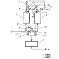
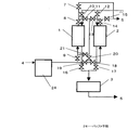
図に示すように、塗装、印刷、工業洗浄など有機溶剤を使用した施設から排出される有機溶剤ガスを含む排ガスは、配管4から本ガス処理装置に導入され配管5より排ガス中の有機溶剤ガスを実質的含まない状態に除去して大気中に排出される。吸着装置1および吸着装置2は、バルブ7からバルブ21を介して配管によって接続されている。図において吸着動作用の配管を実線で、脱着動作用の配管を点線で示している。ここで、吸着装置1および吸着装置2には、吸着剤として目的とする有機溶剤ガスを吸着できる活性炭、ゼオライト、アルミナ、シリカゲルなどの吸着剤が、粒状もしくはペレットもしくはハニカム状の基材に担持した形で充填されている。また、吸着装置1および吸着装置2には、脱着手段3が接続されている。ここで、脱着手段3は、吸着剤に吸着した有機溶剤を脱着することができるものであれば、当該既知の方法を用いることができる。例えば、吸着剤を加熱して脱着を行う方法として、吸着剤を加熱する、加熱空気を送る、ボイラーなどによって加熱した水蒸気を送るなどが挙げられる、また、圧力によって脱着を行う方法として、真空ポンプによって吸着剤の雰囲気を減圧し、さらに、パージエアーを流して脱着する方法やそれに加熱を加える方法がある。ここでは、脱着手段3を真空ポンプとして減圧による脱着動作を行っている場合を説明する。
As shown in the figure, exhaust gas containing organic solvent gas discharged from facilities using organic solvents such as painting, printing, industrial cleaning, etc. is introduced into the gas processing apparatus from the
以上のように構成したガス処理装置について図2から図5を用いてその動作について説明する。 The operation of the gas processing apparatus configured as described above will be described with reference to FIGS.
図2は、吸着装置1が吸着動作、吸着装置2が脱着動作を行っている状態を示すブロック図である。図において、使用している配管系を太線で、また、開いているバルブを白塗り、閉じているバルブを黒塗りで示している。
FIG. 2 is a block diagram illustrating a state in which the
配管4からファンやブロアなどの送風機によって導入した有機溶剤ガスを含む排ガスは、バルブ9を介して吸着装置1に入る。吸着装置1では、吸着剤によって排ガス中の有機溶剤を吸着除去する。吸着装置1を通った排ガスは、バルブ8およびバルブ7を通って配管5より実質的に有機溶剤ガスを含まない状態となって大気に放出される。
Exhaust gas containing an organic solvent gas introduced from the
また、同時に、吸着装置2は、脱着動作を行っており、吸着装置2は、脱着手段3の真空ポンプによってバルブ17を介して数kPa程度の圧力に減圧され、さらに、配管22よりバルブ12を介して脱着用のパージエアーが導入されている。吸着装置2の吸着剤に吸着していた有機溶剤は、減圧とパージエアーによって吸着剤から脱着され高濃度の有機溶剤を含むガスとして配管6から次の処理工程、例えば、液化や分解などに供給される。
At the same time, the
吸着装置2の吸着剤に吸着していた有機溶剤の脱着が終了すると次の動作に移る。
When the desorption of the organic solvent adsorbed on the adsorbent of the
図3は、図2に示す動作の次の動作として、吸着装置1および吸着装置2が吸着動作を行っている状態を示すブロック図である。
FIG. 3 is a block diagram showing a state in which the
図に示すように、配管4からファンやブロアなどの送風機によって導入した有機溶剤ガスを含む排ガスは、バルブ9を介して吸着装置1に入る。吸着装置1では、吸着剤によって排ガス中の有機溶剤を吸着除去する。吸着装置1を通った排ガスは、バルブ8およびバルブ11およびバルブ20およびバルブ18を介して吸着装置2に導入され、吸着装置2においても吸着剤によって排ガス中の有機溶剤を吸着除去して、バルブ14およびバルブ15を介して実質的に有機溶剤ガスを含まない状態となって大気に放出される。
As shown in the figure, exhaust gas containing an organic solvent gas introduced from a
ここで、吸着装置1は、図2に示す動作から継続して吸着動作を行っている。そのため、徐々に吸着剤は破過に近づき吸着装置1の出口ガス濃度は高くなっていくが、後段に吸着装置2が接続されているため、本ガス処理装置から排出されるガスは実質的に有機溶剤ガスを含まない状態を維持することができる。本動作は、吸着装置1の吸着剤に十分な量の吸着剤が吸着するまで継続する。
Here, the
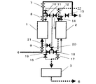
図4は、吸着装置1が脱着動作、吸着装置2が吸着動作を行っている状態を示すブロック図である。吸着装置1の吸着剤が図3で示した動作で十分に有機溶剤を吸着すると、配管4からファンやブロアなどの送風機によって導入した有機溶剤ガスを含む排ガスは、バルブ19およびバルブ18を介して吸着装置2に導入され吸着剤によって排ガス中の有機溶剤を吸着除去し、吸着装置2を通った排ガスはバルブ14およびバルブ15を介して配管5から実質的に有機溶剤ガスを含まない状態となって大気に放出される。吸着装置1は脱着動作に切替わり、脱着手段3の真空ポンプによってバルブ16を介して数kPa程度の圧力に減圧され、さらに、配管22よりバルブ10を介して脱着用のパージエアーが導入されている。吸着装置1の吸着剤に吸着していた有機溶剤は、減圧とパージエアーによって吸着剤から脱着され高濃度の有機溶剤を含むガスとして配管6から次の処理工程、例えば、液化や分解などに供給される。
FIG. 4 is a block diagram showing a state where the
吸着装置1の吸着剤に吸着していた有機溶剤の脱着が終了すると次の動作に移る。
When the desorption of the organic solvent adsorbed on the adsorbent of the
図5は、吸着装置2および吸着装置1が吸着動作を行っている状態を示すブロック図である。
FIG. 5 is a block diagram showing a state in which the
図において、配管4からファンやブロアなどの送風機によって導入した有機溶剤ガスを含む排ガスは、バルブ19およびバルブ18を介して吸着装置2に導入され吸着剤によって排ガス中の有機溶剤を吸着除去し、吸着装置2を通った排ガスはバルブ14およびバルブ13およびバルブ21を介して吸着装置1に導入され、吸着装置1においても吸着剤によって排ガス中の有機溶剤を吸着除去して、バルブ8およびバルブ7を介して配管5より実質的に有機溶剤ガスを含まない状態となって大気に放出される。
In the figure, exhaust gas containing organic solvent gas introduced from a
ここでも図3における動作と同様に、吸着装置2は、徐々に吸着剤は破過に近づき吸着装置2の出口ガス濃度は高くなっていくが、後段に吸着装置1が接続されているため、本ガス処理装置から排出されるガスは実質的に有機溶剤ガスを含まない状態を維持することができる。本動作は、吸着装置2の吸着剤に十分な量の吸着剤が吸着するまで継続し、吸着装置2の吸着が終了すると図2の動作に切替わって、以降、図2から図5の動作を繰り返す。
Here, similarly to the operation in FIG. 3, the
ここで、各動作の切り替えは、予め設定した時間によってタイマーなどを用いて行うことができる。 Here, each operation can be switched using a timer or the like according to a preset time.
ここでは、吸着装置が2つの場合を説明したが、3つ以上の吸着装置を用いても同様の作用、効果が得られる。その場合、脱着動作が終了した吸着装置は、吸着動作を行っている吸着装置の最後段に配置する。最後段とは、直列に配置した吸着装置の最も出口側を意味する。 Here, the case where there are two adsorption devices has been described, but the same operation and effect can be obtained even if three or more adsorption devices are used. In this case, the adsorption device that has completed the desorption operation is disposed at the last stage of the adsorption device that is performing the adsorption operation. The last stage means the most outlet side of the adsorption device arranged in series.
以上のように、脱着動作を終了した吸着装置を吸着動作中の吸着装置の後段に配置することによって、前段の吸着装置の排出ガスの濃度が高くなっても、後段の吸着装置によって除去することができる。そのため、前段の吸着装置の吸着剤が破過後も吸着動作を継続することができ、吸着剤への吸着量を増やすことができる。そのため、吸着剤の使用量を削減できるとともに、脱着ガスを高濃度化することができ、装置の小型化、低価格化が可能となるとともに、排ガスからの有機溶剤を確実に除去できるガス処理装置を提供することができる。 As described above, by disposing the adsorption device that has completed the desorption operation at the subsequent stage of the adsorption device that is in the adsorption operation, even if the concentration of the exhaust gas from the previous adsorption device becomes high, it is removed by the subsequent adsorption device. Can do. Therefore, the adsorption operation can be continued even after the adsorbent of the preceding adsorption device breaks through, and the adsorption amount to the adsorbent can be increased. Therefore, the amount of adsorbent used can be reduced, the concentration of desorbed gas can be increased, the apparatus can be reduced in size and price, and the organic solvent from the exhaust gas can be reliably removed. Can be provided.
(実施の形態2)
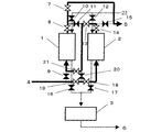
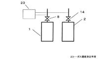
図6は、本発明のガス処理装置の構成の一部を示すブロック図である。なお、本発明実施の形態1と同一の部分には同一番号を付して説明は省略する。図において、破過検知手段としてガス濃度測定手段23が、吸着装置1および吸着装置2の出口に接続され、ガス濃度を測定する。ここで、破過検知手段として、ガス濃度測定手段23を挙げたが、吸着剤の破過を検知できる方法であれば良く、吸着剤の温度測定、吸着剤の重量測定などの方法も用いることができる。
(Embodiment 2)
FIG. 6 is a block diagram showing a part of the configuration of the gas processing apparatus of the present invention. The same parts as those in the first embodiment of the present invention are denoted by the same reference numerals and description thereof is omitted. In the figure, gas concentration measuring means 23 as breakthrough detecting means is connected to the outlets of the
また、ガス濃度測定手段23としては、目的とする有機溶剤の濃度を測定できる方法であれば当該既知の方法を用いることができる。たとえば、FID方式の測定装置、PID方式の測定装置、NDIR方式の測定装置などが挙げられる。特に、半導体式のガスセンサを用いれば、小型で低価格な装置で有機溶剤ガス濃度を測定することが可能となる。 As the gas concentration measuring means 23, any known method can be used as long as it can measure the concentration of the target organic solvent. For example, an FID type measuring device, a PID type measuring device, an NDIR type measuring device, and the like can be given. In particular, if a semiconductor type gas sensor is used, the organic solvent gas concentration can be measured with a small and low-cost apparatus.
上記構成において、ガス濃度測定手段23で吸着装置1および吸着装置2の吸着動作時の出口ガスを測定することにより、吸着装置内の吸着剤の有機溶剤ガスの吸着量を知ることができるため、あらかじめ吸着装置内の吸着剤が十分に有機溶剤ガスを吸着して、かつ十分に有機溶剤ガスを除去できる濃度を設定することによって脱着動作への切り替えを判断することができる。
In the above configuration, by measuring the outlet gas during the adsorption operation of the
そのため、ガス処理装置に導入される排ガス中の有機溶剤ガス濃度が変動しても、吸着装置の吸着剤への吸着量を安定化することができるので、吸着剤の使用量を低減できる。また、脱着ガスの濃度も安定化することができる。 For this reason, even if the concentration of the organic solvent gas in the exhaust gas introduced into the gas treatment device fluctuates, the amount of adsorption to the adsorbent of the adsorber can be stabilized, so that the amount of adsorbent used can be reduced. In addition, the concentration of the desorption gas can be stabilized.
よって、装置の小型化で低価格化が可能となり、確実な有機溶剤ガスの除去が可能となる。 Therefore, it is possible to reduce the cost by reducing the size of the apparatus, and it is possible to reliably remove the organic solvent gas.
(実施の形態3)
図7および図8は、本発明のガス処理装置の構成を示すブロック図である。なお、本発明実施の形態1、2と同一の部分には同一番号を付して説明は省略する。
(Embodiment 3)
7 and 8 are block diagrams showing the configuration of the gas processing apparatus of the present invention. In addition, the same number is attached | subjected to the part same as
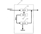
図7において、バッファ手段24は、配管4からファンやブロアなどの送風機によって導入した有機溶剤ガスを含む排ガスを導入し、その濃度変動を緩和して吸着動作中の吸着装置1もしくは吸着装置2に導入する。
In FIG. 7, the buffer means 24 introduces exhaust gas containing organic solvent gas introduced from a
ここで、バッファ手段24は、導入した排ガスの濃度変動を緩和できる方法であれば良い。たとえば、吸着剤を充填した槽をもちいれば、吸着剤の吸放出特性を利用して排ガスの濃度変動を緩和することができる。この場合、比較的小さな容量で構成することが可能である。 Here, the buffer means 24 may be any method that can alleviate the concentration fluctuation of the introduced exhaust gas. For example, if a tank filled with an adsorbent is used, the concentration fluctuation of the exhaust gas can be mitigated by utilizing the absorption / release characteristics of the adsorbent. In this case, it is possible to configure with a relatively small capacity.
また、目的とする有機溶剤を揮発させることによって、濃度変動を緩和することができる。この場合は、排ガスの有機溶剤濃度を高濃度にして濃度変動を緩和するもので、吸着装置の吸着剤への吸着量を増加することができる。 Further, the concentration fluctuation can be alleviated by volatilizing the target organic solvent. In this case, the organic solvent concentration of the exhaust gas is increased to reduce the concentration fluctuation, and the amount of adsorption to the adsorbent of the adsorption device can be increased.
また、さらに目的とする有機溶剤溶液中にバブリングすることでさらに高濃度化し、濃度変動を低減することが可能となる。 Further, by bubbling in the target organic solvent solution, it is possible to further increase the concentration and reduce the concentration fluctuation.
また、図8に示すように、希釈手段25をバッファ手段24の出口に接続することにより、吸着装置1および2に導入する排ガスの濃度調整をすることができ、より濃度変動を緩和することができる。ここで、希釈手段25は、ファンやブロアなどの送風機で希釈するための空気を導入するものである。
Further, as shown in FIG. 8, by connecting the diluting means 25 to the outlet of the buffer means 24, the concentration of the exhaust gas introduced into the
以上のように、バッファ手段24を吸着装置の前段に設け、吸着装置に導入する排ガスの濃度変動を緩和することにより、吸着剤への有機溶剤ガスの吸着量を安定化できるため、吸着剤の使用量を低減できる。 As described above, the buffer means 24 is provided in the front stage of the adsorption device, and the amount of organic solvent gas adsorbed on the adsorbent can be stabilized by reducing the concentration fluctuation of the exhaust gas introduced into the adsorption device. The amount used can be reduced.
そのため、装置を小型化できるとともに脱着ガスの濃度を安定化することが可能となり、確実なガスの除去ができる。 Therefore, the apparatus can be downsized and the concentration of the desorbed gas can be stabilized, so that reliable gas removal can be achieved.
(実施の形態4)
図9は、本発明の排ガス処理装置のシステムの構成を示すブロック図である。なお、本発明実施の形態1〜3と同一の部分には同一番号を付して説明は省略する。
(Embodiment 4)
FIG. 9 is a block diagram showing the configuration of the system of the exhaust gas treatment apparatus of the present invention. In addition, the same number is attached | subjected to the part same as Embodiment 1-3 of this invention, and description is abbreviate | omitted.
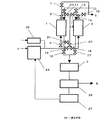
図において、液化手段26は、脱着手段3である真空ポンプから導入された有機溶剤ガスを含む脱着ガスを冷却して液化する。液化後のガスは、配管6より放出される。さらに、液化した有機溶剤液は、液だめ27に貯められて、その一部はバッファ手段24に供給する。ここで、液化手段26は、冷凍サイクルなどの冷却装置によって冷却を行う。
In the figure, the liquefying means 26 cools and liquefies the desorption gas containing the organic solvent gas introduced from the vacuum pump as the desorption means 3. The liquefied gas is discharged from the
上記構成において、脱着ガスから液化手段によって有機溶剤ガスを液化することにより、回収して再利用することができるとともに、バッファ手段に有機溶剤を用いる場合、液化した有機溶剤をバッファ手段に供給することが可能となる。 In the above configuration, by liquefying the organic solvent gas from the desorption gas by the liquefaction means, it can be recovered and reused, and when the organic solvent is used for the buffer means, the liquefied organic solvent is supplied to the buffer means. Is possible.
(実施の形態5)
図10は、本発明の排ガス処理装置の構成を示すブロック図である。なお、本発明実施の形態1〜4と同一の部分には同一番号を付して説明は省略する。
(Embodiment 5)
FIG. 10 is a block diagram showing the configuration of the exhaust gas treatment apparatus of the present invention. In addition, the same number is attached | subjected to the part same as Embodiment 1-4 of this invention, and description is abbreviate | omitted.
図において、分解手段28は、脱着手段3である真空ポンプから導入された有機溶剤ガスを含む脱着ガス中の有機溶剤を分解して実質的に無害な状態にして配管6より大気に放出する。ここで、分解手段28は、目的とする有機溶剤ガスを分解できるものであれば当該既知の方法を用いることができる。例えば、燃焼による分解、燃焼触媒、光触媒、紫外線、オゾン、プラズマによる分解、微生物、酵素などである。
In the figure, the decomposition means 28 decomposes the organic solvent in the desorption gas including the organic solvent gas introduced from the vacuum pump as the desorption means 3 to make it substantially harmless and releases it from the
上記構成において、分解手段で脱着ガス中の有機溶剤ガスを分解することにより、確実に排ガス中の有機溶剤ガスを除去して、無害な状態で大気に放出できる。 In the above configuration, by decomposing the organic solvent gas in the desorption gas by the decomposing means, the organic solvent gas in the exhaust gas can be reliably removed and released into the atmosphere in a harmless state.
印刷や塗装、接着、化学製品製造、工業用洗浄などの揮発性有機溶剤を排出する施設に取り付け、排出のガス処理装置として有用である。 Installed in facilities that discharge volatile organic solvents, such as printing, painting, bonding, chemical product manufacturing, industrial cleaning, etc., it is useful as an exhaust gas treatment device.
1 吸着装置
2 吸着装置
3 脱着手段
23 ガス濃度測定手段
24 バッファ手段
25 希釈手段
26 液化手段
28 分解手段
DESCRIPTION OF
Claims (16)
Priority Applications (1)
| Application Number | Priority Date | Filing Date | Title |
|---|---|---|---|
| JP2005300033A JP2007105657A (en) | 2005-10-14 | 2005-10-14 | Gas treatment apparatus |
Applications Claiming Priority (1)
| Application Number | Priority Date | Filing Date | Title |
|---|---|---|---|
| JP2005300033A JP2007105657A (en) | 2005-10-14 | 2005-10-14 | Gas treatment apparatus |
Publications (1)
| Publication Number | Publication Date |
|---|---|
| JP2007105657A true JP2007105657A (en) | 2007-04-26 |
Family
ID=38031930
Family Applications (1)
| Application Number | Title | Priority Date | Filing Date |
|---|---|---|---|
| JP2005300033A Pending JP2007105657A (en) | 2005-10-14 | 2005-10-14 | Gas treatment apparatus |
Country Status (1)
| Country | Link |
|---|---|
| JP (1) | JP2007105657A (en) |
Cited By (12)
| Publication number | Priority date | Publication date | Assignee | Title |
|---|---|---|---|---|
| JP2009045520A (en) * | 2007-08-15 | 2009-03-05 | Tokyo Metropolitan Industrial Technology Research Institute | Volatile organic substance removal apparatus and volatile organic substance detection method |
| JP2009125670A (en) * | 2007-11-22 | 2009-06-11 | Tokyo Metropolitan Industrial Technology Research Institute | System for monitoring time of exchange of adsorbing vessel and apparatus for treating volatile organic compound waste gas equipped with the same |
| WO2012120948A1 (en) * | 2011-03-04 | 2012-09-13 | 東邦化工建設株式会社 | Method for removing organic solvent, and removal device |
| KR101477100B1 (en) * | 2013-07-26 | 2014-12-29 | 현대제철 주식회사 | Active carbon handling device for absorbing column |
| CN104828897A (en) * | 2015-05-15 | 2015-08-12 | 浙江沐源环境工程有限公司 | Granular activated coke/carbon filtration adsorption experimental facility |
| JP2017154920A (en) * | 2016-03-01 | 2017-09-07 | 昭和電工株式会社 | Ammonia removal facility and removal method, manufacturing device and manufacturing method of hydrogen gas, fuel cell and transportation machine |
| WO2018101255A1 (en) * | 2016-12-01 | 2018-06-07 | 東洋紡株式会社 | Organic solvent recovery system and organic solvent recovery method |
| KR101907622B1 (en) * | 2017-09-29 | 2018-10-12 | 창성엔지니어링 주식회사 | Concentrate catalytic combustion system with active concentration rate control means |
| KR20200065288A (en) * | 2018-11-30 | 2020-06-09 | (주)에프테크 | Exhaust gas measuring system and apparatus based on monitoring of operating state about processing of exhaust gas |
| CN113617149A (en) * | 2021-08-09 | 2021-11-09 | 安徽燃博智能科技有限公司 | VOC (volatile organic compound) waste gas treatment device for environment-friendly equipment |
| KR102473105B1 (en) * | 2021-10-21 | 2022-12-02 | 창성엔지니어링 주식회사 | Simultaneous treatment of harmful gases including ethyl acetate, hydrogen sulfide and ammonia from exhaust gas |
| CN117019399A (en) * | 2023-07-24 | 2023-11-10 | 广州华科环保工程有限公司 | Integrated equipment for classifying pretreatment after centralized collection of multicomponent organic waste gas |
-
2005
- 2005-10-14 JP JP2005300033A patent/JP2007105657A/en active Pending
Cited By (21)
| Publication number | Priority date | Publication date | Assignee | Title |
|---|---|---|---|---|
| JP2009045520A (en) * | 2007-08-15 | 2009-03-05 | Tokyo Metropolitan Industrial Technology Research Institute | Volatile organic substance removal apparatus and volatile organic substance detection method |
| JP2009125670A (en) * | 2007-11-22 | 2009-06-11 | Tokyo Metropolitan Industrial Technology Research Institute | System for monitoring time of exchange of adsorbing vessel and apparatus for treating volatile organic compound waste gas equipped with the same |
| KR101715826B1 (en) | 2011-03-04 | 2017-03-27 | 토호 케미컬 엔지니어링 앤드 컨스트럭션 가부시키가이샤 | Method for removing organic solvent, and removal device |
| WO2012120948A1 (en) * | 2011-03-04 | 2012-09-13 | 東邦化工建設株式会社 | Method for removing organic solvent, and removal device |
| JP2012183462A (en) * | 2011-03-04 | 2012-09-27 | Toho Kako Kensetsu Kk | Method and apparatus for removal of organic solvent |
| KR20140009270A (en) * | 2011-03-04 | 2014-01-22 | 토호 케미컬 엔지니어링 앤드 컨스트럭션 가부시키가이샤 | Method for removing organic solvent, and removal device |
| KR101477100B1 (en) * | 2013-07-26 | 2014-12-29 | 현대제철 주식회사 | Active carbon handling device for absorbing column |
| CN104828897A (en) * | 2015-05-15 | 2015-08-12 | 浙江沐源环境工程有限公司 | Granular activated coke/carbon filtration adsorption experimental facility |
| JP2017154920A (en) * | 2016-03-01 | 2017-09-07 | 昭和電工株式会社 | Ammonia removal facility and removal method, manufacturing device and manufacturing method of hydrogen gas, fuel cell and transportation machine |
| WO2018101255A1 (en) * | 2016-12-01 | 2018-06-07 | 東洋紡株式会社 | Organic solvent recovery system and organic solvent recovery method |
| JPWO2018101255A1 (en) * | 2016-12-01 | 2019-10-24 | 東洋紡株式会社 | Organic solvent recovery system and organic solvent recovery method |
| JP7103226B2 (en) | 2016-12-01 | 2022-07-20 | 東洋紡株式会社 | Organic solvent recovery system and organic solvent recovery method |
| CN110035816A (en) * | 2016-12-01 | 2019-07-19 | 东洋纺株式会社 | Recovery system for organic solvent and organic solvent recovery method |
| KR101907622B1 (en) * | 2017-09-29 | 2018-10-12 | 창성엔지니어링 주식회사 | Concentrate catalytic combustion system with active concentration rate control means |
| WO2019066399A1 (en) * | 2017-09-29 | 2019-04-04 | 창성엔지니어링 주식회사 | Concentrated catalyst combustion system having active concentration ratio control means |
| KR20200065288A (en) * | 2018-11-30 | 2020-06-09 | (주)에프테크 | Exhaust gas measuring system and apparatus based on monitoring of operating state about processing of exhaust gas |
| KR102131116B1 (en) * | 2018-11-30 | 2020-07-07 | (주)에프테크 | Exhaust gas measuring system and apparatus based on monitoring of operating state about processing of exhaust gas |
| CN113617149A (en) * | 2021-08-09 | 2021-11-09 | 安徽燃博智能科技有限公司 | VOC (volatile organic compound) waste gas treatment device for environment-friendly equipment |
| KR102473105B1 (en) * | 2021-10-21 | 2022-12-02 | 창성엔지니어링 주식회사 | Simultaneous treatment of harmful gases including ethyl acetate, hydrogen sulfide and ammonia from exhaust gas |
| CN117019399A (en) * | 2023-07-24 | 2023-11-10 | 广州华科环保工程有限公司 | Integrated equipment for classifying pretreatment after centralized collection of multicomponent organic waste gas |
| CN117019399B (en) * | 2023-07-24 | 2024-04-05 | 广州华科环保工程有限公司 | Integrated equipment for classifying pretreatment after centralized collection of multicomponent organic waste gas |
Similar Documents
| Publication | Publication Date | Title |
|---|---|---|
| JP2007105657A (en) | Gas treatment apparatus | |
| JP5990722B2 (en) | Volatile organic compound recovery equipment | |
| JP2004351312A (en) | Method and apparatus for regenerating activated carbon and air purifying system with the activated carbon incorporated | |
| KR102202900B1 (en) | Apparatus for recovery of volatile organic compounds and method for recovery of volatile organic compounds | |
| JP6318580B2 (en) | Organic solvent recovery system | |
| JP2008073642A (en) | Multi-purpose gas treatment device and its operation method | |
| JP2007000733A5 (en) | ||
| JP2013132582A (en) | Organic solvent-containing gas treatment system | |
| KR20020057852A (en) | A Method for Recovery and Removal of Volatile Organic Compounds, and An Apparatus Using the Method | |
| JP2007260605A (en) | Gas treatment apparatus | |
| JP4911139B2 (en) | Removal and recovery of volatile organic compounds | |
| JP2007014919A (en) | Exhaust gas treatment device and exhaust gas treatment system | |
| JPH1157372A (en) | Method of recovering hydrocarbon vapor using cooling condensation | |
| JP5318333B2 (en) | Method and apparatus for treating fluorine compound-containing gas | |
| KR200287399Y1 (en) | An Apparatus for Recovery and Removal of Volatile Organic Compounds | |
| JP4973817B2 (en) | Removal and recovery of volatile organic compounds | |
| JP3922449B2 (en) | Organic solvent recovery system | |
| JP2006088001A (en) | Concentration method of volatile organic gas and volatile organic gas concentration device | |
| JP2004161503A (en) | Gas purification method | |
| JPH03270710A (en) | Solvent recovery apparatus | |
| JP3788814B2 (en) | Solvent recovery method | |
| JP6201231B2 (en) | Denitration method and denitration apparatus | |
| JPH06254395A (en) | Method for regenerating adsorbent in pressure swing adsorption for recovering co2 | |
| JP5358899B2 (en) | Apparatus for treating volatile organic compound and method for treating volatile organic compound | |
| JP2010063989A (en) | Method of removing and recovering volatile organic compound |