JP2007077658A - Construction method for bridge girder - Google Patents
Construction method for bridge girder Download PDFInfo
- Publication number
- JP2007077658A JP2007077658A JP2005266424A JP2005266424A JP2007077658A JP 2007077658 A JP2007077658 A JP 2007077658A JP 2005266424 A JP2005266424 A JP 2005266424A JP 2005266424 A JP2005266424 A JP 2005266424A JP 2007077658 A JP2007077658 A JP 2007077658A
- Authority
- JP
- Japan
- Prior art keywords
- steel
- bridge girder
- web
- concrete
- floor slab
- Prior art date
- Legal status (The legal status is an assumption and is not a legal conclusion. Google has not performed a legal analysis and makes no representation as to the accuracy of the status listed.)
- Pending
Links
Images


Abstract
Description
本願発明は、道路橋、鉄道橋、歩道橋等に用いられる橋桁に係り、特に、コンクリートからなる上床板と、鋼ウェブとを有する橋桁の構築方法に関する。 The present invention relates to a bridge girder used for a road bridge, a railway bridge, a pedestrian bridge, and the like, and more particularly, to a method for constructing a bridge girder having an upper floor board made of concrete and a steel web.
コンクリート、特にプレストレストコンクリートで形成される橋桁は、一般にコンクリートの上床版と、この下側に連続して形成されるウェブと、このウェブの下端部において断面を拡大するように形成される下フランジとを備えている。下フランジは、複数のウェブの下端部を互いに連結し、下床版として全体を箱形の断面とすることも多く行われている。このようなコンクリートで構築される橋桁では重量が大きく、軽量化による基礎や下部構造への負担軽減が望まれており、ウェブをコンクリートに代えて鋼部材で構成することが提案されている。 A bridge girder formed of concrete, in particular prestressed concrete, generally has an upper floor slab of concrete, a web formed continuously below this, and a lower flange formed to enlarge the cross section at the lower end of the web. It has. In many cases, the lower flange connects the lower end portions of a plurality of webs to each other to form a box-shaped cross section as a whole as a lower floor slab. Such a bridge girder constructed with concrete is heavy, and it is desired to reduce the burden on the foundation and the substructure by reducing the weight, and it has been proposed that the web be made of steel members instead of concrete.
また、ウェブは橋桁の軸線方向に連続するように形成されるのが一般的であるが、軸線方向の連続していると、コンクリートの上床版又は下フランジ(下床版)にプレストレスを導入しようとしたときに、上床版又は下フランジが橋桁の軸線方向に変形しようとするのをウェブが拘束することになり、効率よくプレストレスを導入できない場合が生じる。 The web is generally formed so as to be continuous in the axial direction of the bridge girder, but if it is continuous in the axial direction, prestress is introduced into the upper floor slab or lower flange (lower floor slab) of the concrete. When trying to do so, the web will restrain the upper floor slab or the lower flange from deforming in the axial direction of the bridge girder, and prestress may not be introduced efficiently.
このため、特許文献1には、コンクリートの上床版と下床版と鋼ウェブとを有する橋桁であって、鋼ウェブを橋桁の軸線方向に分割して設ける橋桁が提案されている。
この橋桁が備える鋼ウェブは、複数の板状部材を橋桁の軸線方向に配列したものであり、この板状部材の各々は、高さ方向の中位より上床版と接合される上辺及び下床版と接合される下辺に近づくにしたがって、軸線方向の長さが徐々に拡大されたものとなっている。そして、板状部材の上辺及び下辺に沿って鋼フランジが接合され、このフランジに植設されたスタッドジベルを上床板又は下床版のコンクリートに埋め込んで接合する。また、橋桁に作用するせん断力によって斜めに圧縮力が作用する方向には、板状部材の側面にスタッドジベルが植設され、該スタッドジベルを埋め込むように、コンクリート製のリブが形成されている。
For this reason,
The steel web provided in this bridge girder is obtained by arranging a plurality of plate-like members in the axial direction of the bridge girder, and each of the plate-like members is joined to the upper floor slab from the middle in the height direction. The length in the axial direction is gradually enlarged as it approaches the lower side joined to the plate. Then, steel flanges are joined along the upper and lower sides of the plate-like member, and stud gibbles planted on the flanges are embedded in the concrete of the upper floor plate or the lower floor plate and joined. Further, in the direction in which the compressive force acts diagonally by the shearing force acting on the bridge girder, a stud gibber is implanted on the side surface of the plate-like member, and a concrete rib is formed so as to embed the stud diver. .
この橋桁では、ウェブを鋼部材とし、その特徴的な形状により軽量化することができる。また、独立した板状部材を配列してウェブを形成するので、現場でウェブを連続した状態に組み立てるための溶接が不要となり、橋桁の構築が容易となってコストが低減される。また、ウェブが軸線方向の変形を拘束することが少なくなり、上床板又は下床版のプレストレスを有効に導入することが可能となる。
しかしながら、上記の橋桁では、その構築方法において次に示すような解決が望まれる課題がある。
鋼製のウェブは、一般に工場において製作されるが、その特徴的な形状を鋼板材から切り出すのに作業工数が多くなり、効率の改善が望まれる。また、鋼板材を有効に利用するための板取り等を改善してより低価格での製作が望まれている。さらに、鋼製のウェブとコンクリート床版とを接合するための鋼フランジは、溶接によって鋼ウェブと接合することになり、溶接に多くの作業工程及び費用を要している。特に、小規模の橋梁や歩道橋等の橋桁を対象とした場合、部材寸法が小さく、鋼重量も小さくなるため、溶接による接合及び鋼板材の切断に要する費用の割合が増加し、これらの費用の削減、工期の短縮が求められている。
However, the bridge girder has a problem that the following solution is desired in its construction method.
Steel webs are generally manufactured in factories, but the number of work steps for cutting out the characteristic shape from a steel plate material increases, and improvement in efficiency is desired. In addition, it is desired to manufacture at a lower price by improving a planing for effectively using a steel plate material. Furthermore, the steel flange for joining the steel web and the concrete floor slab is joined to the steel web by welding, and many work steps and costs are required for welding. In particular, when targeting bridge girders such as small-scale bridges and pedestrian bridges, the size of members is small and the weight of steel is also small, so the proportion of costs required for joining by welding and cutting of steel plate materials increases. Reduction and shortening of construction period are required.
本願発明は、上記のような事情に鑑みてなされたものであり、その目的は、コンクリートの床版と鋼ウェブとを有する橋桁において、鋼ウェブを形成するための溶接作業及び鋼板材から部材を切り出す作業を低減し、製作費用の削減及び後期の短縮を図ることである。 This invention is made | formed in view of the above situations, The objective is in the bridge girder which has a concrete floor slab and a steel web, the member is made from the welding operation and steel plate material for forming a steel web. The work to cut out is to reduce the production cost and the latter period.
上記課題を解決するために、請求項1に係る発明は、 圧延によって断面がI型又はH型に形成された型鋼のウェブ部分を、2つの対向するフランジとの接合部付近から台形状のウェブ板が交互に突き出すように切断する工程と、 切断分離された前記フランジの双方から突き出した前記台形状のウェブ板の頂部を互いに接合する工程と、 対向する前記フランジを上下に配置し、上側のフランジと密接するようにコンクリートの上床版を形成する工程とを含む橋桁の構築方法を提供する。
In order to solve the above-described problem, the invention according to
この方法では、型鋼のウェブ部分を切断することにより、フランジから台形状のウェブ板が垂直に突き出した二つの部材が同時に形成される。そして、これらの部材を、上フランジから台形状のウェブ板が下方に突き出した状態、及び下フランジから台形状のウェブ板が上方に突き出した状態に支持し、台形状のウェブ板の頂部同士を突き合わせて接合することにより、型鋼の寸法より大きい高さの桁状の鋼部材が形成される。そして、上下のウェブ板は接合されて、複数の板状の鋼ウェブが橋桁の軸線方向に配列されたものとなる。これらの鋼ウェブは、高さ方向の中位より前記上床版と接合される上辺及び下辺に近づくにしたがって橋桁の軸線方向の寸法が拡大された形状すなわち鼓型又は蝶型となる。このような鋼桁が少なくともコンクリートの上床版と接合され、これらが一体となって曲げモーメント及びせん断力に対して有効に抵抗するものとなる。 In this method, two members in which a trapezoidal web plate vertically protrudes from the flange are formed simultaneously by cutting the web portion of the steel mold. And these members are supported in a state in which the trapezoidal web plate projects downward from the upper flange and in a state in which the trapezoidal web plate projects upward from the lower flange, and the tops of the trapezoidal web plates are supported. By joining them together, a girder-shaped steel member having a height larger than that of the steel mold is formed. Then, the upper and lower web plates are joined, and a plurality of plate-shaped steel webs are arranged in the axial direction of the bridge beam. These steel webs have a shape in which the axial dimension of the bridge girder is enlarged, that is, a drum shape or a butterfly shape, as approaching the upper side and the lower side joined to the upper floor slab from the middle in the height direction. Such steel girders are joined to at least the concrete upper floor slabs, and they are integrated to effectively resist bending moments and shear forces.
また、上記のように鋼ウェブを製作するときに、型鋼の上下のフランジは、鋼ウェブと既に連続したものとなっており、鋼ウェブとフランジを溶接等で接合する必要がなくなる。これにより鋼部材の溶接量が大幅に低減され、製作コストの削減、工期の短縮が可能となる。 Further, when the steel web is manufactured as described above, the upper and lower flanges of the mold steel are already continuous with the steel web, and it is not necessary to join the steel web and the flange by welding or the like. As a result, the welding amount of the steel member is greatly reduced, and the manufacturing cost can be reduced and the construction period can be shortened.
請求項2に係る発明は、請求項1に記載の橋桁の構築方法において、 前記型鋼の下側のフランジと密接するようにコンクリートフランジを形成する工程を含むものとする。
The invention according to
このようにコンクリートフランジを形成する工程を含むことにより、コンクリートフランジは上床版とともに橋桁の曲げ剛性を大きくすることに寄与し、大きな曲げモーメントに抵抗することが可能となる。また、鋼ウェブが橋桁の軸線方向に間隔をあけて配置されることになるが、コンクリートフランジは鋼ウェブ間でせん断力に対して有効に抵抗するものとなる。
上記コンクリートフランジを形成する工程は、分割した型鋼を接合した後又は接合する前に工場で行うのが望ましく、管理された環境で品質の良好なコンクリートフランジを製作することができる。そして、工場で製作することにより現場での作業が低減され、工期の短縮が可能となる。
By including the step of forming the concrete flange in this way, the concrete flange contributes to increasing the bending rigidity of the bridge girder together with the upper floor slab, and can resist a large bending moment. In addition, although the steel webs are arranged at intervals in the axial direction of the bridge girder, the concrete flange effectively resists the shearing force between the steel webs.
The step of forming the concrete flange is desirably performed in a factory after joining the divided steel shapes or before joining, and a high-quality concrete flange can be manufactured in a controlled environment. And, manufacturing at the factory reduces the work at the site, and shortens the construction period.
請求項3に係る発明は、請求項1に記載の橋桁の構築方法において、 前記型鋼の下側のフランジと密接するようにコンクリートの下床版を形成する工程を含み、 コンクリートからなる前記上床版及び下床版と、これらを連結する複数の鋼ウェブとで、断面形状を箱型とする。
The invention according to
形鋼の上フランジに接合されたコンクリートの上床版に加えて、下側のフランジに密接してコンクリートの下床版が形成されることにより、この橋桁の剛性が大きくなり、特に箱形とすることによってねじりに対する剛性が増大する。 In addition to the concrete upper floor slab joined to the upper flange of the section steel, the concrete lower floor slab is formed in close contact with the lower flange, so that the rigidity of this bridge girder increases, especially in the form of a box. This increases the rigidity against torsion.
以上説明したように、本願発明では、鋼ウェブが軸線方向に分割して配列されている橋桁において、鋼ウェブを構成する部材の溶接量を低減し、橋桁の製作費用を低減するとともに、工期を短縮することが可能となる。 As described above, in the present invention, in the bridge girder in which the steel web is divided and arranged in the axial direction, the welding amount of the members constituting the steel web is reduced, the manufacturing cost of the bridge girder is reduced, and the work period is reduced. It can be shortened.
以下、本願発明の実施の形態について説明する。
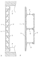
図1は、本願発明の一実施形態である橋桁の側面図及び断面図であり、図2は、同じ橋桁の下方からの斜視図である。また、図3は、同じ橋桁の桁端付近を示す側面図である。
この橋桁2は、対峙する2基の橋台1a、1b間に支持された単純桁となっており、コンクリートからなる上床版11と、その下方に支持されるコンクリートの下床版12と、上記上床版11と下床版12とを連結し、ウェブとして機能する鋼部材13とで主要部が構成され、上記上床版11と下床版12と鋼部材13とで箱形の断面となっている。
Embodiments of the present invention will be described below.
FIG. 1 is a side view and a sectional view of a bridge girder according to an embodiment of the present invention, and FIG. 2 is a perspective view of the same bridge girder from below. FIG. 3 is a side view showing the vicinity of the end of the same bridge girder.
The
上記上床版11は、鋼部材13上に現場で打設されたコンクリートによって形成されており、この上に路面が形成されるものであり、橋桁と直角方向にPC鋼材(図示しない)が配置されている。そして、これらのPC鋼材を緊張し、コンクリートに定着することによってプレストレスが導入されており、車両等の荷重によって上床版に作用する曲げモーメントに対して抵抗するものとなっている。なお、本例では橋桁の軸線方向にはプレストレスが導入されてないが、橋桁が連続桁、ラーメン構造となる場合には、上床版にもプレストレスを導入することができる。
一方、下床版12には、橋軸方向にプレストレスが導入され、桁に作用する正の曲げモーメントに対して、下床版のコンクリートに過度の引張応力が生じないようになっている。
The
On the other hand, prestress is introduced into the
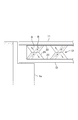
上記鋼部材13は、図4に示すように、鋼ウェブ21と、その上辺に沿って両側へほぼ直角に張り出した上フランジ22及び下辺に沿って両側へ張り出した下フランジ23とで主要部が構成されている。
As shown in FIG. 4, the
上記鋼ウェブ21は、上辺と下辺との中間位置で幅が最も小さく、上辺又は下辺に近づくに従って幅すなわち桁の軸線方向の寸法が直線的に拡大されており、鼓形となっている。上フランジ22及び下フランジ23は、上記鋼ウェブ21の上縁又は下縁に連続しており、上フランジ23の上面および下フランジ23の下面には、複数のスタッドジベル24が植設されている。
The
上記鋼ウェブ21の箱形断面の内側となる面にも、せん断力の作用時に圧縮応力が作用する斜め方向に沿って、複数のスタッドジベル25が植設されている。そして、鋼ウェブ21を形成する鋼板に密接するとともに、上記スタッドジベル25を埋め込むようにコンクリート部材27が形成されている。このコンクリート部材27は斜め方向の柱状となり、せん断力作用時の斜め圧縮力を負担するものである。
A plurality of
上床版11および下床版12のコンクリートは、上記上フランジ22の上面又は下フランジ23の下面に密接するとともに、上記スタッドジベル24を埋め込むように形成されており、これによって上床版11と鋼部材13と下床版12とが一体となっている。
The concrete of the
このような橋桁では、鋼ウェブが上下方向の中位部分で軸線方向の寸法が小さく、上辺及び下辺に近づくにつれて拡大された鼓のような形状をしている。したがって、せん断力が作用した時は、図3に示すように、鋼ウェブには斜め方向の引張力Aと、これに交差する方向の圧縮力Bとが作用して、せん断力に対して有効に抵抗する。そして、柱状のコンクリート部材27は、斜め方向の圧縮力Bの一部を分担し、鋼ウェブ21の座屈を防止する。
In such a bridge girder, the steel web has a small axial dimension at the middle part in the vertical direction, and has a drum-like shape that is enlarged as it approaches the upper side and the lower side. Therefore, when a shearing force is applied, as shown in Fig. 3, the steel web is effective against the shearing force due to the tensile force A in the diagonal direction and the compressive force B in the direction crossing it. Resist. The columnar
また、鋼部材13は、鼓形の鋼ウェブ21が橋桁の軸線方向に分割して配列されているので、軸線方向のプレストレスが導入された時に、鋼ウェブが軸線方向の変形を拘束することが少ない。したがって、少ない緊張材で有効にプレストレスを導入することができる。
Moreover, since the
次に、上記橋桁の構築方法について説明する。
上記橋桁の構築に用いられる鋼部材13は、圧延によって形成された型鋼で、一般にH型鋼又はI型鋼と称されるものを加工して形成されたものである。その製作は、工場又は現場付近に設けられた製作ヤードで行うのが望ましく、次のような工程によって行うことができる。
Next, the construction method of the bridge girder will be described.
The
最初の工程において、図5(a)に示すように、圧延によって断面がI型又はH型に形成された型鋼30のウェブ部分31に、切断線34をマーキングする。この切断線は、2つの対向するフランジの一方33との接合部付近から反対側のフランジ32との接合部付近に向けて軸線と斜め方向に切断するように設定する。そして、反対側のフランジ32との接合部付近を軸線方向に所定長を切断した後、再び反対側のフランジ33との接合部付近に向けて斜め方向に切断する。その後、フランジ33との接合部付近を軸線方向に切断し、再び反対側のフランジ32に向けて斜め方向に切断するものとし、これを繰り返すものである。このとき軸線に沿って切断する長さ及び斜め方向の切断線の角度は、全て同じに設定する。
In the first step, as shown in FIG. 5A, a cutting
このように設定された切断線のマーキングに沿ってウェブ部分を切断すると、図5(b)に示すように二つのフランジ32,33が分離され、これらのフランジ32,33から同じ寸法の台形状のウェブ板31’が同じ間隔で突き出したものが形成される。切断は、機械的に切断するものであっても良いし、ガス溶断でもよい。このようにして切断された二つの部材の位置を移動し、接合部付近から台形状に交互に突き出したウェブ板31’の頂部が互いに突き合わされるように配置する。そして、双方のフランジから突き出した台形状のウェブ板31’の頂部を互いに突きあわせ、これらを接合する。接合は溶接するのが望ましいが、添設板を用いて高力ボルトで接合するものであってもよい。
When the web portion is cut along the marking of the cutting line set as described above, the two
上記のように一旦二つに分割された型鋼を再度接合することにより,上下二つのフランジ22,23と、軸線方向に分割され、間隔を空けた位置で上下のフランジに接合された鋼ウェブ21とを有する桁状の鋼部材13が形成される。
By rejoining the mold steel once divided into two as described above, the upper and
上記鋼部材13の上フランジ22の上面、下フランジ23の下面及び鋼ウェブ21の側面には複数のスタッドジベル24、25を溶接によって植設した後、図6(a)に示すようにこの鋼部材13を横に倒した状態で支持する。そして、鋼ウェブ21の側面と密着するとともに、この鋼ウェブ21に植設されたスタッドジベル25を埋め込むようにコンクリートを打設し、柱状のコンクリート部材27を形成する。
A plurality of
次に、下側のフランジに密接するようにコンクリートの下床版12の一部となる部材12aを形成する。この工程は、図6(b)に示すように鋼部材13の上下を逆にして支持し、型枠41を設けてコンクリートを打設する。このとき、コンクリート部材12aからは側方に複数の鉄筋42が突出するように配置しておく。
Next, the
コンクリートが硬化した後、上記鋼部材13を橋桁の架設現場に搬入し、図7に示すように所定の位置に支持する。設置する橋台1上には積層ゴム等からなる支承3を設けておき、この上に載置する。鋼部材13の据え付けは、製作した工場又は製作ヤード等からトレーラー等で現場に搬入し、大型クレーン車により吊り上げ、所定の位置に架設する。スパンが20m程度の小規模な橋桁の場合は、運搬及び吊り上げて所定の位置に架設することが可能な限り、支間で連続した桁として製作し、分割製作されたものを接合することは行わない。
After the concrete is hardened, the
工場等で製作された鋼部材13が架設現場の所定の位置に設置されると、図7に示すように下床版のコンクリートを打設するための型枠を設け、コンクリートを打設して下床版12を形成する。このとき、予め鋼部材13と一体に形成されたコンクリート部材12aから突き出した鉄筋42を埋め込むようにコンクリートを打設して、下床版12を強固に一体とする。その後、図8に示すように上床版を形成するための型枠44を設け、上フランジ22に植設されたスタッドジベル24を埋め込むようにコンクリートを打設し、鋼部材13と一体となる上床版11を形成する。その後、必要なプレストレスを導入して橋桁を所定の位置で構築する工程を終了する。
When the
なお、上記実施形態では鋼部材13の下側には、コンクリートの下床版12が接合されているが、複数の鋼部材13についてそれぞれ独立したコンクリートフランジを接合するものであってもよい。また、規模の小さい橋桁では、鋼部材の下フランジ23で引張力に抵抗するものとして、コンクリートフランジを省略するものであってもよい。
In the above-described embodiment, the concrete
1:橋台、 2:橋桁、 3:支承、 11:上床版、 12:下床版、 13:鋼部材、 21:鋼ウェブ、 22:上フランジ、 23:下フランジ、 24,25:スタットジベル、 27:コンクリー一ト部材、
30:型鋼、 31:型鋼のウェブ部分、 32,33:形鋼のフランジ、 34:切断線、
41:型枠、 42:鉄筋、 43,44:型枠、
1: abutment, 2: bridge girder, 3: bearing, 11: upper floor slab, 12: lower floor slab, 13: steel member, 21: steel web, 22: upper flange, 23: lower flange, 24, 25: stat gibber, 27: Concrete member,
30: mold steel, 31: web portion of the mold steel, 32, 33: flange of the shape steel, 34: cutting line,
41: formwork, 42: rebar, 43, 44: formwork,
Claims (3)
切断分離された前記フランジの双方から突き出した前記台形状のウェブ板の頂部を互いに接合する工程と、
対向する前記フランジを上下に配置し、上側のフランジと密接するようにコンクリートの上床版を形成する工程とを含むことを特徴とする橋桁の構築方法。 Cutting the web part of the steel plate whose cross section is formed into an I-type or an H-type by rolling so that trapezoidal web plates protrude alternately from the vicinity of the joint with two opposing flanges;
Joining the tops of the trapezoidal web plates protruding from both of the cut and separated flanges;
A method for constructing a bridge girder, comprising: arranging the flanges facing each other vertically and forming an upper floor slab of concrete so as to be in close contact with the upper flange.
Forming a concrete lower floor slab so as to be in close contact with a lower flange of the mold steel, and a cross-sectional shape of the upper floor slab and the lower floor slab made of concrete and a plurality of steel webs connecting them. The bridge girder construction method according to claim 1, wherein the bridge girder is a box shape.
Priority Applications (1)
| Application Number | Priority Date | Filing Date | Title |
|---|---|---|---|
| JP2005266424A JP2007077658A (en) | 2005-09-14 | 2005-09-14 | Construction method for bridge girder |
Applications Claiming Priority (1)
| Application Number | Priority Date | Filing Date | Title |
|---|---|---|---|
| JP2005266424A JP2007077658A (en) | 2005-09-14 | 2005-09-14 | Construction method for bridge girder |
Publications (1)
| Publication Number | Publication Date |
|---|---|
| JP2007077658A true JP2007077658A (en) | 2007-03-29 |
Family
ID=37938250
Family Applications (1)
| Application Number | Title | Priority Date | Filing Date |
|---|---|---|---|
| JP2005266424A Pending JP2007077658A (en) | 2005-09-14 | 2005-09-14 | Construction method for bridge girder |
Country Status (1)
| Country | Link |
|---|---|
| JP (1) | JP2007077658A (en) |
Cited By (9)
| Publication number | Priority date | Publication date | Assignee | Title |
|---|---|---|---|---|
| CN102094390A (en) * | 2010-11-12 | 2011-06-15 | 无锡国电华新起重运输设备有限公司 | Trolley track of port loading and unloading bridge |
| CN102251479A (en) * | 2011-04-28 | 2011-11-23 | 中交第二公路工程局有限公司 | Device and method for positioning and adjusting corrugated steel webs |
| CN102733308A (en) * | 2012-06-19 | 2012-10-17 | 中铁八局集团昆明铁路建设有限公司 | Method for connecting steel guide girder with box girder |
| CN103850170A (en) * | 2012-11-29 | 2014-06-11 | 中铁工程设计咨询集团有限公司 | Double rail supporting table type rail transit U-shaped beam |
| CN104074130A (en) * | 2014-07-16 | 2014-10-01 | 山东莱钢建设有限公司 | Abutting-connecting opening connecting structure of box-type bridge single body and box-type bridge |
| KR101455632B1 (en) | 2013-08-07 | 2014-10-28 | 주식회사 화인플랜택 | Manufacturing method of prestressed honeycomb I-girder and construction method of bridge using that I-girder |
| CN105040567A (en) * | 2015-05-06 | 2015-11-11 | 浙江东南网架股份有限公司 | Interchange steel bridge and manufacture method thereof |
| CN105714684A (en) * | 2016-02-24 | 2016-06-29 | 中国一冶集团有限公司 | Prestressed concrete variable cross-section fish-bellied type continuous box girder construction method |
| CN106758742A (en) * | 2016-12-29 | 2017-05-31 | 中国冶集团有限公司 | A kind of curved variable cross-section fish-bellied type Steel Continuous Box beam and its construction method |
Citations (6)
| Publication number | Priority date | Publication date | Assignee | Title |
|---|---|---|---|---|
| JPS50140920U (en) * | 1974-05-09 | 1975-11-20 | ||
| JPS5316622U (en) * | 1976-07-24 | 1978-02-13 | ||
| JPH01501853A (en) * | 1987-01-23 | 1989-06-29 | オピトノエ、プロイズボドストベンノ―チエフニチエスコエ、プレドプリアチエ “エネルゴチエフプロム” | Manufacturing method of lightweight shapes |
| JPH10252217A (en) * | 1997-03-14 | 1998-09-22 | Kataoka Kikuichi | Transformed shape steel |
| JPH11324221A (en) * | 1998-05-22 | 1999-11-26 | Showa Alum Corp | Lightweight metal structural material and its manufacture |
| JP2002220812A (en) * | 2001-01-25 | 2002-08-09 | Sumitomo Constr Co Ltd | Bridge girder |
-
2005
- 2005-09-14 JP JP2005266424A patent/JP2007077658A/en active Pending
Patent Citations (6)
| Publication number | Priority date | Publication date | Assignee | Title |
|---|---|---|---|---|
| JPS50140920U (en) * | 1974-05-09 | 1975-11-20 | ||
| JPS5316622U (en) * | 1976-07-24 | 1978-02-13 | ||
| JPH01501853A (en) * | 1987-01-23 | 1989-06-29 | オピトノエ、プロイズボドストベンノ―チエフニチエスコエ、プレドプリアチエ “エネルゴチエフプロム” | Manufacturing method of lightweight shapes |
| JPH10252217A (en) * | 1997-03-14 | 1998-09-22 | Kataoka Kikuichi | Transformed shape steel |
| JPH11324221A (en) * | 1998-05-22 | 1999-11-26 | Showa Alum Corp | Lightweight metal structural material and its manufacture |
| JP2002220812A (en) * | 2001-01-25 | 2002-08-09 | Sumitomo Constr Co Ltd | Bridge girder |
Cited By (11)
| Publication number | Priority date | Publication date | Assignee | Title |
|---|---|---|---|---|
| CN102094390A (en) * | 2010-11-12 | 2011-06-15 | 无锡国电华新起重运输设备有限公司 | Trolley track of port loading and unloading bridge |
| CN102251479A (en) * | 2011-04-28 | 2011-11-23 | 中交第二公路工程局有限公司 | Device and method for positioning and adjusting corrugated steel webs |
| CN102733308A (en) * | 2012-06-19 | 2012-10-17 | 中铁八局集团昆明铁路建设有限公司 | Method for connecting steel guide girder with box girder |
| CN102733308B (en) * | 2012-06-19 | 2014-03-26 | 中铁八局集团昆明铁路建设有限公司 | Method for connecting steel guide girder with box girder |
| CN103850170A (en) * | 2012-11-29 | 2014-06-11 | 中铁工程设计咨询集团有限公司 | Double rail supporting table type rail transit U-shaped beam |
| KR101455632B1 (en) | 2013-08-07 | 2014-10-28 | 주식회사 화인플랜택 | Manufacturing method of prestressed honeycomb I-girder and construction method of bridge using that I-girder |
| CN104074130A (en) * | 2014-07-16 | 2014-10-01 | 山东莱钢建设有限公司 | Abutting-connecting opening connecting structure of box-type bridge single body and box-type bridge |
| CN105040567A (en) * | 2015-05-06 | 2015-11-11 | 浙江东南网架股份有限公司 | Interchange steel bridge and manufacture method thereof |
| CN105714684A (en) * | 2016-02-24 | 2016-06-29 | 中国一冶集团有限公司 | Prestressed concrete variable cross-section fish-bellied type continuous box girder construction method |
| CN106758742A (en) * | 2016-12-29 | 2017-05-31 | 中国冶集团有限公司 | A kind of curved variable cross-section fish-bellied type Steel Continuous Box beam and its construction method |
| CN106758742B (en) * | 2016-12-29 | 2019-08-23 | 中国一冶集团有限公司 | A kind of curved variable cross-section fish-bellied type Steel Continuous Box beam and its construction method |
Similar Documents
| Publication | Publication Date | Title |
|---|---|---|
| KR100427405B1 (en) | Pssc complex girder | |
| JP2007077658A (en) | Construction method for bridge girder | |
| KR100609304B1 (en) | Precast Composition I-Beam with Concrete Panel and Corrugated Steel Web Girder | |
| JP5053016B2 (en) | Girder structure using corrugated steel web | |
| JP2007016594A (en) | Synthetic panel structure, panel bridge structure, and construction method for continuous synthetic beam bridge | |
| KR101270733B1 (en) | Prestressed Concrete Box Girder Integrated with Steel Deck and Constructing Method of Bridge using Such Girder | |
| JP2003268719A (en) | Steel-concrete composite beam and its installation method | |
| JPH09221717A (en) | Steel-concrete composite floor-slab bridge and construction method thereof | |
| JP2006009449A (en) | Truss panel girder and precast truss panel | |
| CN105064200A (en) | Prestressed ferroconcrete combined simply-supported beam bridge with preprocessed assembled fish-bellied truss frame and construction method of prestressed ferroconcrete combined simply-supported beam bridge | |
| JP2009102826A (en) | Girder bridge with reinforced concrete composite steel floor slab | |
| KR20080093261A (en) | Composite bridge construction method | |
| KR101940876B1 (en) | Composite girder and construction method thereof | |
| KR101049963B1 (en) | Steel plate structure and construction method of wall-slab joint structure using same | |
| JP2014105547A (en) | Structure for fixing precast floor slab | |
| JP2008088634A (en) | Composite steel-concrete floor slab | |
| JP4005774B2 (en) | Bridge girder | |
| KR100622452B1 (en) | Multi-H section steel girder compounded part | |
| KR20050018358A (en) | Structure of continuous PSC beam with connection member and steel cross beam and bridge construction method using the same | |
| JP5439016B2 (en) | Buried formwork | |
| JP7329432B2 (en) | Rahmen Viaduct and Construction Method of Rahmen Viaduct | |
| JP3682521B2 (en) | Structure of two-stage main girder composite floor slab bridge | |
| JPH11303022A (en) | Bridge composite floor slab | |
| KR20080004752U (en) | Composite bridge | |
| KR200291793Y1 (en) | Pssc complex girder |
Legal Events
| Date | Code | Title | Description |
|---|---|---|---|
| A621 | Written request for application examination |
Free format text: JAPANESE INTERMEDIATE CODE: A621 Effective date: 20080318 |
|
| A977 | Report on retrieval |
Free format text: JAPANESE INTERMEDIATE CODE: A971007 Effective date: 20100104 |
|
| A131 | Notification of reasons for refusal |
Free format text: JAPANESE INTERMEDIATE CODE: A131 Effective date: 20100323 |
|
| A02 | Decision of refusal |
Free format text: JAPANESE INTERMEDIATE CODE: A02 Effective date: 20100713 |