JP2007040238A - Electromagnetic driving valve - Google Patents
Electromagnetic driving valve Download PDFInfo
- Publication number
- JP2007040238A JP2007040238A JP2005227004A JP2005227004A JP2007040238A JP 2007040238 A JP2007040238 A JP 2007040238A JP 2005227004 A JP2005227004 A JP 2005227004A JP 2005227004 A JP2005227004 A JP 2005227004A JP 2007040238 A JP2007040238 A JP 2007040238A
- Authority
- JP
- Japan
- Prior art keywords
- valve
- push plate
- electromagnetically driven
- drive
- stem
- Prior art date
- Legal status (The legal status is an assumption and is not a legal conclusion. Google has not performed a legal analysis and makes no representation as to the accuracy of the status listed.)
- Withdrawn
Links
Images


Classifications
-
- F—MECHANICAL ENGINEERING; LIGHTING; HEATING; WEAPONS; BLASTING
- F01—MACHINES OR ENGINES IN GENERAL; ENGINE PLANTS IN GENERAL; STEAM ENGINES
- F01L—CYCLICALLY OPERATING VALVES FOR MACHINES OR ENGINES
- F01L1/00—Valve-gear or valve arrangements, e.g. lift-valve gear
- F01L1/26—Valve-gear or valve arrangements, e.g. lift-valve gear characterised by the provision of two or more valves operated simultaneously by same transmitting-gear; peculiar to machines or engines with more than two lift-valves per cylinder
-
- F—MECHANICAL ENGINEERING; LIGHTING; HEATING; WEAPONS; BLASTING
- F01—MACHINES OR ENGINES IN GENERAL; ENGINE PLANTS IN GENERAL; STEAM ENGINES
- F01L—CYCLICALLY OPERATING VALVES FOR MACHINES OR ENGINES
- F01L9/00—Valve-gear or valve arrangements actuated non-mechanically
- F01L9/20—Valve-gear or valve arrangements actuated non-mechanically by electric means
- F01L9/21—Valve-gear or valve arrangements actuated non-mechanically by electric means actuated by solenoids
- F01L2009/2105—Valve-gear or valve arrangements actuated non-mechanically by electric means actuated by solenoids comprising two or more coils
- F01L2009/2109—The armature being articulated perpendicularly to the coils axes
Abstract
Description
この発明は、一般的には、電磁駆動弁に関し、より特定的には、内燃機関に用いられ、電磁力と弾性力とによって駆動する回転式の電磁駆動弁に関するものである。 The present invention relates generally to an electromagnetically driven valve, and more particularly to a rotary electromagnetically driven valve used in an internal combustion engine and driven by electromagnetic force and elastic force.
従来、電磁駆動弁は、たとえば米国特許第6,467,441号明細書(特許文献1)に開示されている。
特許文献1では、ディスク(アーマチュア)に支点を持つ回転駆動式の電磁駆動弁が開示されている。しかしながら、1つのバルブを1つのアクチュエータで駆動するので、駆動回路コストが高いという問題があった。また、部品点数も多いという問題があった。
そこで、この発明は上述のような問題点を解決するためになされたものであり、部品点数を削減することができる電磁駆動弁を提供することを目的とする。 Therefore, the present invention has been made to solve the above-described problems, and an object thereof is to provide an electromagnetically driven valve that can reduce the number of parts.
この発明に従った電磁駆動弁は電磁力により作動する電磁駆動弁であって、弁軸を有し、弁軸が延びる方向に沿って往復運動する複数の駆動弁と、弁軸と連動する一方端から他方端ヘ延び、他方端で延びる中心軸を中心に揺動する揺動部材と、揺動部材を支持する支持部材と、揺動部材に押圧されて複数の駆動弁を駆動させるプッシュプレートとを備える。1つのプッシュプレートが2以上の駆動弁を駆動させる。 The electromagnetically driven valve according to the present invention is an electromagnetically driven valve that is operated by electromagnetic force, and has a valve shaft and reciprocates along the direction in which the valve shaft extends, A swing member that swings from one end to the other end and swings about a central axis that extends from the other end, a support member that supports the swing member, and a push plate that is pressed by the swing member and drives a plurality of drive valves With. One push plate drives two or more drive valves.
このように構成された電磁駆動弁では、1つのプッシュプレートが2以上の駆動弁を駆動させるため1つのプッシュプレートが1つの駆動弁のみを駆動させる場合に比べて揺動部材の数を減らすことができる。また、その揺動部材を駆動するコイルの数も減らすことができる。その結果部品点数を削減することができ、さらに消費電力の低減も可能となる。 In the electromagnetically driven valve configured as described above, since one push plate drives two or more drive valves, the number of oscillating members can be reduced as compared with the case where one push plate drives only one drive valve. Can do. In addition, the number of coils that drive the swing member can be reduced. As a result, the number of parts can be reduced, and further power consumption can be reduced.
好ましくは、揺動部材とプッシュプレートとの間に介在するステムをさらに備え、ステムとプッシュプレートとは球面接触する。この場合、球面接触とすることで、面圧が低減できるので、ステムがクリアランスにより傾いても、接触部の磨耗を低減でき、耐久性を向上させることができる。 Preferably, a stem interposed between the swing member and the push plate is further provided, and the stem and the push plate are in spherical contact. In this case, since the surface pressure can be reduced by the spherical contact, the wear of the contact portion can be reduced and the durability can be improved even if the stem is inclined by the clearance.
好ましくは、電磁駆動弁は複数の駆動弁を揺動部材に向かって付勢する第一および第二付勢部材をさらに備える。第一付勢部材の付勢力は第二付勢部材の付勢力よりも大きく、第一付勢部材が付勢する駆動弁はプッシュプレートに固着される。この場合第一付勢部材側の駆動弁がプッシュプレートに固着されるため、他方側の駆動弁に遊びが設けられ複数の駆動弁をプッシュプレートが支持しやすくなり、リフト量が一定となる。 Preferably, the electromagnetically driven valve further includes first and second urging members that urge the plurality of drive valves toward the swing member. The biasing force of the first biasing member is larger than the biasing force of the second biasing member, and the drive valve biased by the first biasing member is fixed to the push plate. In this case, since the drive valve on the first urging member side is fixed to the push plate, play is provided on the other drive valve so that the push plate can easily support the plurality of drive valves, and the lift amount becomes constant.
好ましくは第二付勢部材が付勢する駆動弁はプッシュプレートに対してバルブステム方向に移動可能にプッシュプレートに保持される。第一および第二駆動弁のリフト量が異なる。この場合プッシュプレートが開弁方向に動いて弁を開弁させるときに、2つの弁にクリアランスの開弁タイミングのずれを発生させることができる。そのため、特に吸気弁において吸気スワール流れを生じさせることができる。 Preferably, the drive valve biased by the second biasing member is held by the push plate so as to be movable in the valve stem direction with respect to the push plate. The lift amounts of the first and second drive valves are different. In this case, when the push plate moves in the valve opening direction to open the valve, a deviation in the opening timing of the clearance between the two valves can be generated. Therefore, an intake swirl flow can be generated particularly in the intake valve.
好ましくは、複数の駆動弁よりも少ない数の付勢部材がプッシュプレートを揺動部材に向かって付勢する。この場合、付勢部材の数を減らすことができる。さらに、複数の付勢部材を設ける必要がないため複数の付勢部材の付勢力の差を考慮する必要がなくなる。 Preferably, a smaller number of biasing members than the plurality of drive valves bias the push plate toward the swing member. In this case, the number of urging members can be reduced. Furthermore, since it is not necessary to provide a plurality of urging members, it is not necessary to consider the difference in urging force between the plurality of urging members.
好ましくは、複数の駆動弁の少なくとも1つのバルブステムとプッシュプレートとを回転可能に接続する回転ジョイント機構と、回転ジョイント機構が設けられた側のバルブステムの開弁動作を停止させる停止部とをさらに備える。この場合他方の弁のみを開弁させることが可能となる。すなわち、両方の弁を開弁させる場合、他方の弁だけを開弁させる場合が可能となり、出力に応じた開弁動作が可能となる。 Preferably, a rotary joint mechanism that rotatably connects at least one valve stem of the plurality of drive valves and the push plate, and a stop portion that stops the valve opening operation of the valve stem on the side where the rotary joint mechanism is provided. Further prepare. In this case, only the other valve can be opened. That is, when both valves are opened, only the other valve can be opened, and a valve opening operation according to the output is possible.
好ましくは、揺動部材からプッシュプレートに力が伝わる位置を複数の駆動弁の並ぶ方向に移動させることが可能な移動部をさらに備える。この場合、他方の弁の開弁リフト量を可変にすることができる。 Preferably, the apparatus further includes a moving unit capable of moving the position where the force is transmitted from the swing member to the push plate in the direction in which the plurality of drive valves are arranged. In this case, the valve opening lift amount of the other valve can be made variable.
好ましくは、プッシュプレートは互いに長手方向にスライド可能な挿入体と被挿入体とを有し、挿入体は回転ジョイント機構を介して一方の駆動弁に接続され、被挿入体は回転ジョイント機構を介して他方の駆動弁に接続され、挿入体と被挿入体とのスライドを停止させるロック機構をさらに備え、揺動部材からプッシュプレートへの力の伝達位置は、プッシュプレートの中心からずれている。この場合、ロック機構のオンオフにより片弁のみの開弁が可能となる。 Preferably, the push plate has an insert and an insert to be slidable in the longitudinal direction, the insert being connected to one drive valve via a rotary joint mechanism, and the insert being connected via a rotary joint mechanism. And a lock mechanism that is connected to the other drive valve and stops the slide between the inserted body and the inserted body, and the transmission position of the force from the swing member to the push plate is shifted from the center of the push plate. In this case, only one valve can be opened by turning on and off the lock mechanism.
この発明に従えば、部品点数が少ない電磁駆動弁を提供することができる。 According to this invention, an electromagnetically driven valve with a small number of parts can be provided.
以下、この発明の実施の形態について、図面を参照して説明する。なお、以下の実施の形態では同一または相当する部分については同一の参照符号を付し、その説明については繰返さない。 Embodiments of the present invention will be described below with reference to the drawings. In the following embodiments, the same or corresponding parts are denoted by the same reference numerals, and description thereof will not be repeated.
(実施の形態1)
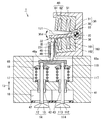
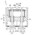
図1は、この発明の実施の形態1に従った電磁駆動弁の断面図である。図1を参照して、電磁駆動弁1は、本体51と、本体51に取付けられた上側電磁石60および下側電磁石160と、上側電磁石60および下側電磁石160に挟まれたディスク30と、ディスク30により駆動されるステム46とを有する。
(Embodiment 1)
FIG. 1 is a cross-sectional view of an electromagnetically driven valve according to
「コ」の字型の本体51はベース部材であり、本体51にさまざまな要素が取付けられる。上側電磁石60および下側電磁石160の各々は、磁性体からなるコア61,161と、そのコア61,161に巻付けられたコイル62,162とを有する。コイルに通電されることで磁力が発生し、この磁力によりディスク30を駆動させる。ディスク30は上側電磁石60および下側電磁石160の間に配置されて、上側電磁石60および下側電磁石160の吸引力によりいずれか一方に吸引される。これにより、上側電磁石60および下側電磁石160間でディスク30が往復運動する。ディスク30の往復運動はステム46に伝えられる。
The “U” -shaped
電磁駆動弁1は電磁力により作動する電磁駆動弁であって、弁軸としてのバルブステム12,112を有し、バルブステム12,112が延びる方向(矢印10)に沿って往復運動をする複数の駆動弁14,114と、駆動弁14,114と距離を隔てた位置に設けられた支持部材としての本体51と、バルブステム12,112に連動する一方端32と、本体51に揺動自在に支持された他方端33とを有し、他方端33で延びる中心軸35を中心に揺動する揺動部材としてのディスク30と、ディスク30に押圧されて複数の駆動弁14,114を駆動させるプッシュプレート68とを備え、1つのプッシュプレート68が2つ以上の駆動弁14,114を駆動させる。
The electromagnetically driven
本実施の形態における電磁駆動弁1は、ガソリンエンジンやディーゼルエンジンなどの内燃機関の吸排気バルブ(吸気弁または排気弁)を構成している。この実施の形態では、吸気ポート18に設けられる吸気弁としての駆動弁の場合を説明するが、排気弁としての駆動弁に本発明を適用してもよい。
The electromagnetically driven
図1で示す電磁駆動弁1は、回転駆動式の電磁駆動弁であり、その運動機構としてディスク30を用いている。本体51はシリンダヘッド41上に設けられる。本体51では、下側に下側電磁石160が設けられ上側に上側電磁石60が設けられる。下側電磁石160は鉄製のコア161と、コア161に巻かれたコイル162とを有する。コイル162に電流を流すことによりコイル162で囲まれた領域に磁界が発生し、この磁界によりディスク30を引き寄せることが可能である。
The electromagnetically driven
上側電磁石60は鉄製のコア61と、コア61に巻付けられたコイル62とを有する。コイル62に電流を流すことによってコイル62で取囲まれた領域に磁界が発生し、この磁界によりディスク30を引き寄せることが可能である。
The
上側電磁石60のコイル62と下側電磁石160のコイル162とは接続されていてもよく、また分離されていてもよい。コア61,161に巻付けられるコイル62,162のターン数は特に限定されるものではない。
The
ディスク30はアーム部31と軸受部38とを有し、アーム部31が一方端32から他方端33へ延びている。アーム部31は上側電磁石60および下側電磁石160により吸引されて矢印30dで示す方向に揺動(回動)する部材である。アーム部31の端部に軸受部38が取付けられ、アーム部31は軸受部38を中心として回動する。アーム部31の上側表面131は上側電磁石60と当接可能であり、下側表面231は下側電磁石160と当接可能である。また、下側表面231はステム46と接触している。
The
軸受部38は円筒形状であり、その内部にはトーションバー36が収納されている。トーションバー36の第一の端部は本体51にスプライン嵌合で嵌め合わされ、他方の端部は軸受部38に嵌め合わされる。これにより軸受部38が回動しようとすると、この回動に逆らう力がトーションバー36から軸受部38へ加えられる。そのため、軸受部38は常に中立状態に位置決めされる。一方端32では、ディスク30と接触するようにステム46が設けられ、ステム46はステムガイド45により案内される。ステム46およびディスク30は矢印30dで示す方向に揺動運動することが可能である。
The bearing
シリンダヘッド41上に本体51が取付けられる。シリンダヘッド41の下部には吸気ポート18が設けられ、吸気ポート18は吸気を燃焼室内へ導入するための経路であり、吸気ポート18内を混合気または空気が通過する。吸気ポート18と燃焼室との間にはバルブシート42が設けられ、バルブシート42により駆動弁14の密閉性を高めることができる。
A
シリンダヘッド41には吸気バルブとしての駆動弁14,114が取付けられている。駆動弁14,114は長手方向に延びるバルブステム12,112と、バルブステム12,112の端部に取付けられた傘部13,113とを有する。バルブステム12,112はステムガイド43により案内される。バルブステム12,112はプッシュプレート68に係合している。バルブステム12,112の上端部はスプリングリテーナ19,119と嵌め合わされており、スプリングリテーナ19,119とともに駆動する。スプリングリテーナ19,119はバルブスプリング17,117により付勢されている。このため、スプリングリテーナ19,119はバルブスプリング17,117によって上方向に付勢される。
Drive
プッシュプレート68が2つの駆動弁14,114のバルブステム12,112と係合している。2つのバルブステム12,112のほぼ中央ではステム46がプッシュプレート68に接触している。ステム46はプッシュプレート68とディスク30との間に介在し、ディスク30から力を受けてプッシュプレート68を押し下げる働きをする。
A
次に、実施の形態1に従った電磁駆動弁の動作について説明する。まず、電磁駆動弁1を駆動させる場合には、上側電磁石60および下側電磁石160のいずれかを構成するコイル62,162のいずれかに電流を流す。たとえば、実施の形態1では、コイル62に電流を流すこととする。これにより、コイル62において磁界が発生し、磁性体から構成されるディスク30のアーム部31は上側電磁石60に引き付けられる。アーム部31が上方向へ回動すれば、トーションバー36が捻られて、このトーションバー36が逆方向へアーム部31を動かそうとする。しかしながら、上側電磁石60による引き付け力が強いため、アーム部31はさらに上方向へ回動し、最後には上側表面131が上側電磁石60と接触する。アーム部31が上方向に動くにつれて、バルブスプリング17,117で上方向に押圧される駆動弁14,114がアーム部31およびプッシュプレート68とともに上方向に移動する。これにより駆動弁14,114が閉じられる。
Next, the operation of the electromagnetically driven valve according to the first embodiment will be described. First, when the electromagnetically driven
次に、駆動弁14を開ける場合には、アーム部31を下方向へ動かす必要がある。この場合には、まずコイル61に流れる電流を止めるか、または小さくする。これにより、上側電磁石60とアーム部31とで働く電磁力が小さくなる。アーム部31には、トーションバー36により捻り力が働いているため、この捻り力(弾性力)が電磁力に打ち勝ち、アーム部31は図1中の中立位置まで移動する。次に、下側電磁石160を構成するコイル162に電流を流す。これにより、コイル162の周囲で磁界が発生し、磁性体からなるアーム部31は下側電磁石160に引き付けられる。なお、このときも駆動弁14のステム46がアーム部31に押されるため下方向に移動する。コイル162による引き付け力がトーションバー36による捻り力に打ち勝ち、最終的には、下側電磁石160に下側表面231が接触する。このときプッシュプレート68および駆動弁14,114も下方向へ動き開弁状態となる。
Next, when opening the
このように、上方向の動きと下方向の動きとを繰返すことにより、アーム部31は矢印30dで示す方向に回動する。アーム部31が回動すると、アーム部31と接続されている軸受部38も回動する。
Thus, by repeating the upward movement and the downward movement, the
このように構成された実施の形態1に従った電磁駆動弁1では、1つのプッシュプレート68で2つの駆動弁14,114を同時に駆動させることができる。これにより、コイル62,162の数を低減することができ、従来と同等な電流でアクチュエータを駆動でき、消費電力を大幅に低減することができる。
In the electromagnetically driven
さらに、1つのバルブを1つのアクチュエータで動かす場合に比べて部品点数を削減できるので製造コストを低下させることができる。さらに、回路を減少させることもできるので、その点においても製造コストを低下させることができる。 Furthermore, since the number of parts can be reduced as compared with the case where one valve is moved by one actuator, the manufacturing cost can be reduced. Further, since the number of circuits can be reduced, the manufacturing cost can be reduced also in this respect.
(実施の形態2)
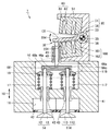
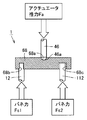
図2は、この発明の実施の形態2に従った電磁駆動弁の断面図である。図3は、図2中のIIIで囲んだ部分を拡大して示す断面図である。図2および図3を参照して、この発明の実施の形態2に従った電磁駆動弁1では、プッシュプレート68とステム46とが球面接触している点で、実施の形態1に従った電磁駆動弁1と異なる。図3では、プッシュプレート68に凹部68aが設けられ、ステム46に凸部46aが設けられているが、これに限られるものではなく、プッシュプレート68に凸部が設けられ、ステム46に凹部が設けられていてもよい。
(Embodiment 2)
FIG. 2 is a cross-sectional view of an electromagnetically driven valve according to Embodiment 2 of the present invention. FIG. 3 is an enlarged cross-sectional view of a portion surrounded by III in FIG. Referring to FIGS. 2 and 3, in electromagnetically driven
ステム46はステムガイド45との間でクリアランスdを有する。この場合にステム46はステムガイド45に対して傾くことがある。しかしながら、ステム46とプッシュプレート68とは球面接触することで面圧を低減でき、耐久性を確保できる。
The
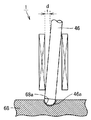
図4は別の電磁駆動弁の一部分の断面図である。図4を参照して、ステム46の先端とプッシュプレート68とが点接触していればこの部分で面圧が大きくなる可能性があり、耐久性の低下の恐れがある。
FIG. 4 is a cross-sectional view of a part of another electromagnetically driven valve. Referring to FIG. 4, if the tip of
このように構成された、実施の形態2に従った電磁駆動弁1では、さらに耐久性を向上させることができる。
In the electromagnetically driven
(実施の形態3)
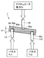
図5は、この発明の実施の形態3に従った電磁駆動弁の断面図である。図6は、図5中のVIで囲んだ部分を拡大して示す断面図である。図5および図6を参照して、この発明の実施の形態3に従った電磁駆動弁1ではバルブステム12がプッシュプレート68に圧入されており、バルブステム112はプッシュプレート68にクリアランスを有するように嵌合している点で、実施の形態1に従った電磁駆動弁1と異なる。プッシュプレート68には2つの凹部68b,68cが設けられ、凹部68bにはバルブステム12が圧入され、凹部68cにはバルブステム112がクリアランスを有するように挿入されている。なお、バルブステム12は必ずしも圧入されているだけでなく、圧入以外の方法でプッシュプレート68に固着されていてもよい。バルブスプリング17,117のばね力(ばね定数)が互いに異なる。具体的には、バルブスプリング17のばね力が大きく(ばね定数が大きく、バルブスプリング117のばね力(ばね定数)が小さい。このようなばね力の相違は意図して設けられるものであってもよく、製造段階において不可避的に発生するものであってもよい。バルブスプリング17のばね力をFs1、バルブスプリング17のばね力をFs2とする。ステム46には、アクチュエータ(上側電磁石60および下側電磁石160)により推力Faが加えられる。開弁動作中の力の関係は、Faがばね力Fs1とばね力Fs2との合計よりも大きい。ばね力が大きいバルブステム12側を圧入することでプッシュプレート68の傾きを防止している。
(Embodiment 3)
FIG. 5 is a cross-sectional view of an electromagnetically driven valve according to Embodiment 3 of the present invention. 6 is an enlarged cross-sectional view of a portion surrounded by VI in FIG. 5 and 6, in electromagnetically driven
図7は、2つのバルブステム12,112がともにクリアランスを有するようにプッシュプレート68に嵌められた構成を示す図である。図7を参照して、凹部68b,68cの両方に、クリアランスを有するようにバルブステム12,112を嵌め合わせた場合には、ばね力が大きいバルブステム12側が上側へ押上げられる。その結果2つのバルブステム12に差が生じバルブリフトの差が生じる。これによりエンジン性能へ影響を与える。図6で示す実施の形態3の構造では、ばね力が大きい側のバルブステムをプッシュプレート68に圧入することでこの問題を解決している。すなわち、実施の形態3では電磁駆動弁は、複数の駆動弁をディスク30に向かって付勢する第一および第二付勢部材としてのバルブスプリング17,117をさらに備える。第一付勢部材としてのバルブスプリング17の付勢力は第二付勢部材としてのバルブスプリング117の付勢力よりも大きく、バルブスプリング17が付勢する駆動弁14のバルブステム12はプッシュプレート68に固着される。
FIG. 7 is a view showing a configuration in which the two valve stems 12 and 112 are fitted to the
(実施の形態4)
図8は、この発明の実施の形態4に従った電磁駆動弁のプッシュプレートの断面図である。図8を参照して、この発明の実施の形態4に従った電磁駆動弁1のプッシュプレート68では、バルブステム112が軸方向にクリアランスdを有するように凹部68cに嵌め合わせられている点で、実施の形態1に従った電磁駆動弁1と異なる。なお、バルブステム12は凹部68bに圧入されている。
(Embodiment 4)
FIG. 8 is a cross-sectional view of a push plate of an electromagnetically driven valve according to Embodiment 4 of the present invention. Referring to FIG. 8, in
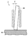
図9から図11は、図8で示す電磁駆動弁の動作を説明するための断面図である。図9を参照して、閉弁時には、2つの駆動弁14,114が閉じられている。このとき、プッシュプレート68とバルブステム112との間にはクリアランスdが生じている。
9 to 11 are cross-sectional views for explaining the operation of the electromagnetically driven valve shown in FIG. Referring to FIG. 9, when the valve is closed, the two
図10を参照して、ステム46がプッシュプレート68を下方向へ移動させるとバルブステム12は圧入されているので下方向へ動く。これに対して、バルブステム112はクリアランスdを有するように凹部68cに挿入されているため、クリアランス分プッシュプレート68が動いたとしても駆動弁114は動かない。その結果、図10では駆動弁14のみが開きクリアランス分だけ駆動弁14が下方向へ移動する。
Referring to FIG. 10, when the
図11を参照して、さらにプッシュプレート68が下方向へ動くと、駆動弁114も下方向へ動く。このとき、駆動弁14と駆動弁114との開き量の差はdとなり、クリアランス分だけリフト差が生じる。
Referring to FIG. 11, when
このように構成された、実施の形態4に従った電磁駆動弁1ではクリアランス分のリフト差が2つの駆動弁14,114で生じる。特に、吸気側において空気のスワール流れを実現し、燃費を向上させることができる。
In the electromagnetically driven
なお、この実施の形態ではクリアランスdに何らの部材も設けなかったが、この部分に弾性体を配置してもよい。 In this embodiment, no member is provided in the clearance d, but an elastic body may be disposed in this portion.
すなわち、第二付勢部材としてのバルブスプリング117が付勢する駆動弁14はプッシュプレート68に対してバルブステム112方向に移動可能にプッシュプレート68に保持され、2つの駆動弁14,114のリフト量が異なる。
That is, the
(実施の形態5)
図12および図13は、この発明の実施の形態5に従った電磁駆動弁の一部分の断面図である。図12および図13を参照して、この発明の実施の形態5に従った電磁駆動弁1ではバルブスプリング17がプッシュプレート68を押圧している点で、実施の形態1に従った電磁駆動弁と異なる。すなわち、実施の形態1ではそれぞれの駆動弁14,114がバルブスプリング17,117で押圧されていたのに対し、実施の形態5ではスプリングリテーナをなくし、バルブスプリング17が直接プッシュプレート68を押圧する。プッシュプレート68とリテーナが一体化されている。ステム46の軸心とバルブスプリング17の軸心が同一となる。
(Embodiment 5)
12 and 13 are sectional views of a part of the electromagnetically driven valve according to the fifth embodiment of the present invention. 12 and 13, in the electromagnetically driven
このように構成された実施の形態5の電磁駆動弁1では、バルブスプリング17をバルブでなくプッシュプレート68へ配置することで、両方の駆動弁14,114において意図するバルブリフトを実現し、かつ部品点数低減によるコストの低減を実施することができる。プッシュプレート68とリテーナを一体化することにより、ばね力のばらつきを考える必要がなく、両方の駆動弁14,114で意図するバルブリフトを実現することができる。また、部品点数低減による低コスト化を図ることができる。すなわち、複数の駆動弁14,114よりも少ない数の付勢部材としてのバルブスプリング17がプッシュプレート68をディスク30に向かって付勢している。
In the electromagnetically driven
(実施の形態6)
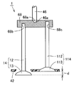
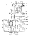
図14は、この発明の実施の形態6に従った電磁駆動弁の一部分の断面図である。図14を参照して、この発明の実施の形態6に従った電磁駆動弁1では、空圧または油圧などによるロック機構67が設けられている点で、実施の形態1に従った電磁駆動弁1と異なる。ロック機構67は矢印67aで示す方向に移動することができ、スプリングリテーナ19の駆動をロックすることができる。図14では閉弁状態を示している。
(Embodiment 6)
FIG. 14 is a cross-sectional view of a part of an electromagnetically driven valve according to Embodiment 6 of the present invention. Referring to FIG. 14, in the electromagnetically driven
図15は、図14で示す電磁駆動弁の動作を説明するための断面図である。図15ではスプリングリテーナ19がロックされた状態の電磁駆動弁を示し、図16ではロックが解除された電磁駆動弁を示す。図15を参照して、ロック機構67により、スプリングリテーナ19がロックされる。バルブステム12とプッシュプレート68との間には回転ジョイント機構66が設けられ、プッシュプレート68はバルブステム12に対して回転することが可能である。図15で示すようにロック機構67によりスプリングリテーナ19をロックした場合には、ステム46が押し下げられてもスプリングリテーナ19は下へ下がらない。その結果駆動弁14が下へ下がらない。これに対し、駆動弁114は下方向へ下がる。そのため、駆動弁114のみが開く。
FIG. 15 is a cross-sectional view for explaining the operation of the electromagnetically driven valve shown in FIG. FIG. 15 shows the electromagnetically driven valve with the
図16を参照して、ロック機構67がスプリングリテーナ19をロックしていない場合には、ステム46が押し下げられればプッシュプレート68により駆動弁14,114の両方が押し下げられる。これにより2つのバルブが開く状態となる。すなわち、実施の形態6では、プッシュプレート68の片側に回転ジョイント機構66を設け、片方のバルブをロックすることにより、1つのアクチュエータで片弁の停止を実現することができる。実施の形態6ではバルブステム12とプッシュプレート68とを回転可能に接続する回転ジョイント機構66と、回転ジョイント機構66が設けられた側のバルブステム12の開閉動作を停止させる停止部としてのロック機構67とを有する。
Referring to FIG. 16, when the
(実施の形態7)
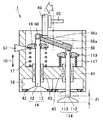
図17は、この発明の実施の形態7に従った電磁駆動弁の一部断面図である。図17を参照して、この発明の実施の形態7に従った電磁駆動弁1では、ステム46を駆動させる移動機構65を有する点で、実施の形態6に従った電磁駆動弁1と異なる。移動機構65は油圧または空圧などによりステム46の位置を移動させる機構であり、矢印65aで示す方向にステム46を移動させることができる。ステム46を左右へ動かすことにより、力の伝達位置が左右へ動き、リフト量を変更することができる。すなわち、実施の形態7では、実施の形態6の構成において、アクチュエータからの力の伝達位置を変えることにより、片弁が停止している状態においてでも一方の弁の可変リフトを実現する。
(Embodiment 7)
FIG. 17 is a partial sectional view of an electromagnetically driven valve according to Embodiment 7 of the present invention. Referring to FIG. 17, the electromagnetically driven
図18は、図17で示すプッシュプレートとステムの斜視図である。図18を参照して、プッシュプレート68には直線状に凹部68aが形成されている。凹部68aは半円筒形状であり、その表面にステム46の先端部の凸部46aが嵌り合っている。ステム46は凹部68aの延びる方向に沿って移動可能である。
FIG. 18 is a perspective view of the push plate and the stem shown in FIG. Referring to FIG. 18, the
図19から図21は移動機構の動作を説明するために示す電磁駆動弁の一部分の断面図である。図19を参照して、移動機構65により、ステム46を左端へ移動させると、ステム46の往復運動により、駆動弁114が大きくリフトする。具体的には、基準となるリフト量との差はd1となる。図20を参照して、基準位置(中央位置)にステム46を位置決めすると、ステム46の駆動に対して、所定量だけ駆動弁114が駆動する。
19 to 21 are cross-sectional views of a part of the electromagnetically driven valve shown to explain the operation of the moving mechanism. Referring to FIG. 19, when the
図21を参照して、ステム46を右方向へ駆動させる。ステム46の往復により、駆動弁114はリフトする。基準値とのリフト量の差はd2である。すなわち、実施の形態7では、ステム46からプッシュプレート68に力が伝わる位置を複数の駆動弁14,114の並ぶ方向に移動させることが可能な移動部としての移動機構65をさらに備える。
Referring to FIG. 21, the
(実施の形態8)
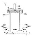
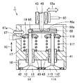
図22は、この発明の実施の形態8に従った電磁駆動弁の一部断面図である。図22を参照して、この発明の実施の形態8に従った電磁駆動弁ではプッシュプレート68が第一部材168および第二部材268により構成されており、第一部材168および第二部材268が互いに長手方向にスライドすることが可能である。さらに、第一部材168の位置を第二部材268に対して固定するロックピン368が設けられており、第一部材168は回転ジョイント機構66によりバルブステム12と接続され、第二部材268は回転ジョイント機構166によりバルブステム12と接続されている。プッシュプレート68は互いに長手方向にスライド可能な挿入体としての第一部材168と被挿入体としての第二部材268とを有し、第一部材168は回転ジョイント機構66を介して一方の駆動弁14に接続され、第二部材268は回転ジョイント機構166を介して他方の駆動弁114に接続され、第一部材168と第二部材268とのスライドを停止させるロックピン368をさらに備え、ステム46からプッシュプレート68への力の伝達位置はプッシュプレート68の中心からずれている。
(Embodiment 8)
FIG. 22 is a partial cross-sectional view of the electromagnetically driven valve according to the eighth embodiment of the present invention. Referring to FIG. 22, in the electromagnetically driven valve according to the eighth embodiment of the present invention, push
図23および図24は、実施の形態8に従った電磁駆動弁の動作を説明するための断面図である。図23を参照して、ロックピンによるロックがオフとされている状態においてステム46がプッシュプレート68を押し下げるとステム46に近い側の駆動弁114に大きな力が加わり、駆動弁114が大きくリフトされる。この結果、リフト量の差はd3となる。図24を参照して、ロックピンが存在する状態でステム46を押し下げると、2つの駆動弁14,114にほぼ均等に力が行き渡るため2つの駆動弁14,114は等しくリフトしリフト差がほぼなくなる。この実施の形態では、プッシュプレート68の両端と駆動弁14,114のバルブステム12,112を回転ジョイント機構66,166で連結している。また、プッシュプレート68にスライドおよびロック機構としてのロックピン368を設けることにより、2つの駆動弁14,114のリフト量に差を生じさせることを可能とする。また、アクチュエータリフトを調整することで片弁の停止も可能とすることができる。
23 and 24 are cross-sectional views for explaining the operation of the electromagnetically driven valve according to the eighth embodiment. Referring to FIG. 23, when the
(実施の形態9)
図25はこの発明の実施の形態9に従った電磁駆動弁の断面図である。図25を参照して、この発明の実施の形態9に従った電磁駆動弁1では、ディスク30が上下で2枚設けられている点で、実施の形態1に従った電磁駆動弁1と異なる。それぞれのディスク30はステム1012で連結されている。
(Embodiment 9)
FIG. 25 is a sectional view of an electromagnetically driven valve according to Embodiment 9 of the present invention. 25, the electromagnetically driven
このように構成された実施の形態9に従った電磁駆動弁でも、実施の形態1に従った電磁駆動弁1と同様の効果がある。
The electromagnetically driven valve according to the ninth embodiment configured as described above has the same effect as the electromagnetically driven
以上、この発明の実施の形態について説明したが、ここで示した実施の形態はさまざまに変形することが可能である。実施の形態2から8では、1枚のディスク30を用いた例を示したが、実施の形態9のように2枚のディスクを用いてもよい。
Although the embodiment of the present invention has been described above, the embodiment shown here can be variously modified. In the second to eighth embodiments, an example in which one
また、上側電磁石60および下側電磁石160を構成するコイル62,162は1本のコイルで構成されてもよく、さらに別のコイルで構成されてもよい。
Moreover, the
今回開示された実施の形態はすべての点で例示であって制限的なものではないと考えられるべきである。本発明の範囲は上記した説明ではなくて特許請求の範囲によって示され、特許請求の範囲と均等の意味および範囲内でのすべての変更が含まれることが意図される。 The embodiment disclosed this time should be considered as illustrative in all points and not restrictive. The scope of the present invention is defined by the terms of the claims, rather than the description above, and is intended to include any modifications within the scope and meaning equivalent to the terms of the claims.
この発明は、たとえば車両に搭載される内燃機関の電磁駆動弁の分野で用いることができる。 The present invention can be used, for example, in the field of an electromagnetically driven valve for an internal combustion engine mounted on a vehicle.
1 電磁駆動弁、12,112 ステム、13,113 傘部、14,114 駆動弁、30 ディスク、32 一方端、33 他方端、46 ステム、51 本体、68 プッシュプレート。
DESCRIPTION OF
Claims (8)
弁軸を有し、前記弁軸が延びる方向に沿って往復運動する複数の駆動弁と、
前記弁軸と連動する一方端から他方端まで延び、前記他方端で延びる中心軸を中心に揺動する揺動部材と、
前記駆動弁を支持する支持部材と、
前記揺動部材に押圧されて前記複数の駆動弁を駆動させるプッシュプレートとを備え、
1つの前記プッシュプレートが2以上の前記駆動弁を駆動させる、電磁駆動弁。 An electromagnetically driven valve that operates by electromagnetic force,
A plurality of drive valves having a valve shaft and reciprocating along a direction in which the valve shaft extends;
An oscillating member extending from one end linked to the valve shaft to the other end and oscillating about a central axis extending at the other end;
A support member for supporting the drive valve;
A push plate that is pressed by the swing member to drive the plurality of drive valves;
An electromagnetically driven valve in which one push plate drives two or more of the drive valves.
Priority Applications (4)
| Application Number | Priority Date | Filing Date | Title |
|---|---|---|---|
| JP2005227004A JP2007040238A (en) | 2005-08-04 | 2005-08-04 | Electromagnetic driving valve |
| US11/492,872 US7418932B2 (en) | 2005-08-04 | 2006-07-26 | Electromagnetically driven valve |
| CNB2006101075710A CN100424323C (en) | 2005-08-04 | 2006-07-26 | Electromagnetically driven valve |
| EP06015544A EP1749981A1 (en) | 2005-08-04 | 2006-07-26 | Electromagnetically driven valve |
Applications Claiming Priority (1)
| Application Number | Priority Date | Filing Date | Title |
|---|---|---|---|
| JP2005227004A JP2007040238A (en) | 2005-08-04 | 2005-08-04 | Electromagnetic driving valve |
Publications (2)
| Publication Number | Publication Date |
|---|---|
| JP2007040238A true JP2007040238A (en) | 2007-02-15 |
| JP2007040238A5 JP2007040238A5 (en) | 2008-08-28 |
Family
ID=37402611
Family Applications (1)
| Application Number | Title | Priority Date | Filing Date |
|---|---|---|---|
| JP2005227004A Withdrawn JP2007040238A (en) | 2005-08-04 | 2005-08-04 | Electromagnetic driving valve |
Country Status (4)
| Country | Link |
|---|---|
| US (1) | US7418932B2 (en) |
| EP (1) | EP1749981A1 (en) |
| JP (1) | JP2007040238A (en) |
| CN (1) | CN100424323C (en) |
Cited By (6)
| Publication number | Priority date | Publication date | Assignee | Title |
|---|---|---|---|---|
| JP2009275708A (en) * | 2009-07-15 | 2009-11-26 | Toyota Motor Corp | Solenoid-driven valve |
| JP2010512488A (en) * | 2006-12-12 | 2010-04-22 | マック トラックス インコーポレイテッド | Valve opening mechanism and method |
| US7913655B2 (en) | 2007-06-07 | 2011-03-29 | Toyota Jidosha Kabushiki Kaisha | Electromagnetically-driven valve |
| JP4782228B2 (en) * | 2006-12-12 | 2011-09-28 | マック トラックス インコーポレイテッド | Valve opening mechanism and method |
| US9528398B2 (en) | 2014-09-16 | 2016-12-27 | Hyundai Motor Company | Variable valve lift apparatus |
| KR20200006288A (en) * | 2018-07-10 | 2020-01-20 | 현대자동차주식회사 | Integrated control device for oil and coolant |
Families Citing this family (4)
| Publication number | Priority date | Publication date | Assignee | Title |
|---|---|---|---|---|
| JP2008303783A (en) * | 2007-06-07 | 2008-12-18 | Toyota Motor Corp | Solenoid driven valve |
| WO2010135145A2 (en) * | 2009-05-21 | 2010-11-25 | Texas Industrial Products, Llc | Apparatus and method for remotely operating manual valves |
| GB2554720B (en) * | 2016-10-06 | 2021-07-14 | Camcon Auto Ltd | Electromagnetic actuator and methods of operation thereof |
| CN110345517B (en) * | 2019-06-13 | 2020-05-05 | 北京鲲鹏神通科技有限公司 | Novel automatic ignition and fire adjusting device for gas stove |
Family Cites Families (19)
| Publication number | Priority date | Publication date | Assignee | Title |
|---|---|---|---|---|
| US4924821A (en) * | 1988-12-22 | 1990-05-15 | General Motors Corporation | Hydraulic lash adjuster and bridge assembly |
| EP0796402B1 (en) * | 1994-11-09 | 2000-05-31 | Aura Systems, Inc. | Hinged armature electromagnetically actuated valve |
| EP1131540B1 (en) | 1998-11-16 | 2003-03-19 | Heinz Leiber | Electromagnetic drive |
| IT1310488B1 (en) * | 1999-09-23 | 2002-02-18 | Magneti Marelli Spa | ELECTROMAGNETIC ACTUATOR FOR THE CONTROL OF THE VALVES OF AN ASCO MOTOR. |
| AU2001243307A1 (en) * | 2000-02-29 | 2001-09-12 | Bombardier Inc. | Four stroke engine having flexible arrangement |
| IT1321181B1 (en) | 2000-05-04 | 2003-12-30 | Magneti Marelli Spa | METHOD AND DEVICE FOR ESTIMATING THE POSITION OF A BODY ACTUATOR IN AN ELECTROMAGNETIC ACTUATOR FOR THE CONTROL OF A |
| DE10025491C2 (en) | 2000-05-23 | 2003-02-20 | Daimler Chrysler Ag | Electromagnetic actuator |
| ITBO20000366A1 (en) | 2000-06-23 | 2001-12-23 | Magneti Marelli Spa | ELECTROMAGNETIC ACTUATOR FOR THE OPERATION OF THE VALVES OF A COMBUSTION ENGINE. |
| DE10035759A1 (en) * | 2000-07-22 | 2002-01-31 | Daimler Chrysler Ag | Electromagnetic poppet valve actuator for motor vehicle internal combustion engine has solenoid mounted in housing to operate on armature |
| DE10053596A1 (en) * | 2000-10-28 | 2002-05-02 | Daimler Chrysler Ag | Electromagnetic actuator for gas exchange valve of IC engine, comprises armature with laminations having apertures forming duct for medium transport |
| DE10120396A1 (en) * | 2001-04-25 | 2002-10-31 | Daimler Chrysler Ag | Adjusting electromagnetic actuator of gas exchange valve of internal combustion engine, by processing effective surfaces of pivot armature and/or magnet |
| JP2003056317A (en) * | 2001-08-09 | 2003-02-26 | Hino Motors Ltd | Valve system of multi-valve engine |
| JP2003217925A (en) * | 2002-01-21 | 2003-07-31 | Mikuni Corp | Linear actuator device and drive control method |
| US6505589B1 (en) * | 2002-02-01 | 2003-01-14 | General Motors Corporation | Single cam three-valve engine overhead valve train |
| DE10220788A1 (en) * | 2002-05-10 | 2003-11-20 | Daimler Chrysler Ag | Electromagnetic actuator for a gas shuttle valve has a pivoted armature fastened to a positioning tube swiveling on its ends on bearings in side walls of a casing |
| JP3935008B2 (en) * | 2002-07-16 | 2007-06-20 | 本田技研工業株式会社 | Engine valve gear |
| US20040055549A1 (en) * | 2002-09-25 | 2004-03-25 | Petrie Tad L. | Variable valve timing system for an internal combustion engine |
| JP2006022776A (en) | 2004-07-09 | 2006-01-26 | Toyota Motor Corp | Solenoid-driven valve |
| JP2006057521A (en) | 2004-08-19 | 2006-03-02 | Toyota Motor Corp | Solenoid drive valve |
-
2005
- 2005-08-04 JP JP2005227004A patent/JP2007040238A/en not_active Withdrawn
-
2006
- 2006-07-26 EP EP06015544A patent/EP1749981A1/en not_active Withdrawn
- 2006-07-26 CN CNB2006101075710A patent/CN100424323C/en not_active Expired - Fee Related
- 2006-07-26 US US11/492,872 patent/US7418932B2/en not_active Expired - Fee Related
Cited By (8)
| Publication number | Priority date | Publication date | Assignee | Title |
|---|---|---|---|---|
| JP2010512488A (en) * | 2006-12-12 | 2010-04-22 | マック トラックス インコーポレイテッド | Valve opening mechanism and method |
| JP4782228B2 (en) * | 2006-12-12 | 2011-09-28 | マック トラックス インコーポレイテッド | Valve opening mechanism and method |
| US7913655B2 (en) | 2007-06-07 | 2011-03-29 | Toyota Jidosha Kabushiki Kaisha | Electromagnetically-driven valve |
| JP2009275708A (en) * | 2009-07-15 | 2009-11-26 | Toyota Motor Corp | Solenoid-driven valve |
| JP4706781B2 (en) * | 2009-07-15 | 2011-06-22 | トヨタ自動車株式会社 | Solenoid valve |
| US9528398B2 (en) | 2014-09-16 | 2016-12-27 | Hyundai Motor Company | Variable valve lift apparatus |
| KR20200006288A (en) * | 2018-07-10 | 2020-01-20 | 현대자동차주식회사 | Integrated control device for oil and coolant |
| KR102451919B1 (en) | 2018-07-10 | 2022-10-06 | 현대자동차 주식회사 | Integrated control device for oil and coolant |
Also Published As
| Publication number | Publication date |
|---|---|
| CN100424323C (en) | 2008-10-08 |
| CN1908387A (en) | 2007-02-07 |
| US20060260572A1 (en) | 2006-11-23 |
| US7418932B2 (en) | 2008-09-02 |
| EP1749981A1 (en) | 2007-02-07 |
Similar Documents
| Publication | Publication Date | Title |
|---|---|---|
| JP2007040238A (en) | Electromagnetic driving valve | |
| US20060196457A1 (en) | Valve actuator assembly | |
| EP1789659B1 (en) | Electromagnetically driven valve | |
| KR970700281A (en) | VARLABLE VALVE TIMING | |
| JP4624330B2 (en) | Variable cam mechanism | |
| JP2007046503A (en) | Solenoid-driven valve | |
| JP2008303765A (en) | Variable valve gear of internal combustion engine | |
| US7387094B2 (en) | Electromagnetically driven valve | |
| US20070221873A1 (en) | Electromagnetically Driven Valve | |
| JP4475198B2 (en) | Solenoid valve | |
| US7913655B2 (en) | Electromagnetically-driven valve | |
| JP4196940B2 (en) | Solenoid valve | |
| JP2008088893A (en) | Supply pump | |
| JP4124183B2 (en) | Electromagnetically driven valve and control method thereof | |
| JP2006070968A (en) | Solenoid driving valve | |
| JP2007040162A (en) | Electromagnetic driving valve | |
| JP4691009B2 (en) | Solenoid valve device for engine | |
| JP2008303783A (en) | Solenoid driven valve | |
| JP4140596B2 (en) | Electromagnetically driven valve and internal combustion engine | |
| JP2007170625A (en) | Electromagnetic drive valve | |
| JP2007064474A (en) | Electromagnetic drive valve | |
| JP2007071187A (en) | Solenoid-driven valve | |
| JP2007046497A (en) | Solenoid-driven valve | |
| JP3628183B2 (en) | Solenoid valve drive | |
| JP2009275708A (en) | Solenoid-driven valve |
Legal Events
| Date | Code | Title | Description |
|---|---|---|---|
| A521 | Request for written amendment filed |
Free format text: JAPANESE INTERMEDIATE CODE: A523 Effective date: 20080710 |
|
| A621 | Written request for application examination |
Free format text: JAPANESE INTERMEDIATE CODE: A621 Effective date: 20080710 |
|
| A761 | Written withdrawal of application |
Free format text: JAPANESE INTERMEDIATE CODE: A761 Effective date: 20081224 |