JP2006057521A - Solenoid drive valve - Google Patents
Solenoid drive valve Download PDFInfo
- Publication number
- JP2006057521A JP2006057521A JP2004239777A JP2004239777A JP2006057521A JP 2006057521 A JP2006057521 A JP 2006057521A JP 2004239777 A JP2004239777 A JP 2004239777A JP 2004239777 A JP2004239777 A JP 2004239777A JP 2006057521 A JP2006057521 A JP 2006057521A
- Authority
- JP
- Japan
- Prior art keywords
- valve
- coil
- stem
- electromagnetic force
- electromagnetically driven
- Prior art date
- Legal status (The legal status is an assumption and is not a legal conclusion. Google has not performed a legal analysis and makes no representation as to the accuracy of the status listed.)
- Pending
Links
Images


Classifications
-
- F—MECHANICAL ENGINEERING; LIGHTING; HEATING; WEAPONS; BLASTING
- F01—MACHINES OR ENGINES IN GENERAL; ENGINE PLANTS IN GENERAL; STEAM ENGINES
- F01L—CYCLICALLY OPERATING VALVES FOR MACHINES OR ENGINES
- F01L9/00—Valve-gear or valve arrangements actuated non-mechanically
- F01L9/20—Valve-gear or valve arrangements actuated non-mechanically by electric means
- F01L9/21—Valve-gear or valve arrangements actuated non-mechanically by electric means actuated by solenoids
- F01L2009/2105—Valve-gear or valve arrangements actuated non-mechanically by electric means actuated by solenoids comprising two or more coils
- F01L2009/2109—The armature being articulated perpendicularly to the coils axes
-
- F—MECHANICAL ENGINEERING; LIGHTING; HEATING; WEAPONS; BLASTING
- F01—MACHINES OR ENGINES IN GENERAL; ENGINE PLANTS IN GENERAL; STEAM ENGINES
- F01L—CYCLICALLY OPERATING VALVES FOR MACHINES OR ENGINES
- F01L9/00—Valve-gear or valve arrangements actuated non-mechanically
- F01L9/20—Valve-gear or valve arrangements actuated non-mechanically by electric means
- F01L9/21—Valve-gear or valve arrangements actuated non-mechanically by electric means actuated by solenoids
- F01L2009/2146—Latching means
- F01L2009/2148—Latching means using permanent magnet
Landscapes
- Engineering & Computer Science (AREA)
- Mechanical Engineering (AREA)
- General Engineering & Computer Science (AREA)
- Valve Device For Special Equipments (AREA)
- Magnetically Actuated Valves (AREA)
Abstract
Description
この発明は、一般的には電磁駆動弁に関し、より特定的には、内燃機関に用いられる回転駆動式の電磁駆動弁に関するものである。 The present invention relates generally to an electromagnetically driven valve, and more specifically to a rotationally driven electromagnetically driven valve used in an internal combustion engine.
従来の電磁駆動弁に関して、たとえば米国特許第6467441号明細書には、電磁力とスプリングとの協働によって内燃機関のバルブが作動する電磁アクチュエータが開示されている(特許文献1)。 Regarding a conventional electromagnetically driven valve, for example, US Pat. No. 6,467,441 discloses an electromagnetic actuator in which a valve of an internal combustion engine is operated by cooperation of electromagnetic force and a spring (Patent Document 1).
特許文献1に開示された電磁アクチュエータは、回転駆動式と呼ばれており、ステムを有するバルブと、そのステムの先端に当接された第2端部およびサポートフレームに揺動自在に支持された第1端部を有する揺動アームとを備える。
従来の電磁駆動弁では、可動部材の質量が大きくなり、この可動部材を駆動させるために大きな力が必要となるため消費電力が大きくなるという問題があった。 The conventional electromagnetically driven valve has a problem in that the mass of the movable member increases, and a large force is required to drive the movable member, resulting in an increase in power consumption.
そこで、この発明は上述のような問題点を解決するためになされたものであり、消費電力を低減させることが可能な電磁駆動弁を提供することを目的とする。 Accordingly, the present invention has been made to solve the above-described problems, and an object thereof is to provide an electromagnetically driven valve capable of reducing power consumption.
この発明の1つの局面に従った電磁駆動弁は、電磁力と弾性力との協働により作動する電磁駆動弁であって、弁軸を有し、弁軸が延びる方向に沿って往復運動する駆動弁と、弁軸に揺動自在に連結された一方端と、ベース部材に揺動自在に支持された他方端とを有し、互いに間隔を隔てて設けられた第1および第2の揺動部材と、コイルを有し、第1の揺動部材と第2の揺動部材との間に配置され、複数の磁気回路を構成する電磁石とを備える。コイルに電流が流れることによって、第1および第2の揺動部材に電磁力が作用する。 An electromagnetically driven valve according to one aspect of the present invention is an electromagnetically driven valve that operates by cooperation of electromagnetic force and elastic force, has a valve shaft, and reciprocates along a direction in which the valve shaft extends. First and second swing valves having a drive valve, one end pivotably connected to the valve shaft, and the other end pivotally supported by the base member and spaced from each other. A moving member and an electromagnet having a coil and disposed between the first rocking member and the second rocking member and constituting a plurality of magnetic circuits. When a current flows through the coil, an electromagnetic force acts on the first and second oscillating members.
この発明に従えば、電磁石は、複数の磁気回路を構成する。このため、電磁石が単一の磁気回路を構成する場合に比べて、複数の磁気回路が第1および第2の揺動部材に作用して第1および第2の揺動部材を駆動させることができる。第1および第2の揺動部材に複数の磁気回路が作用して第1および第2の揺動部材が駆動するため、第1および第2の揺動部材に分散して力が加わる。その結果、第1および第2の揺動部材の強度を小さくしても第1および第2の揺動部材が破損することがない。その結果、第1および第2の揺動部材の質量を小さくでき、消費電力を低減することが可能となる。 According to this invention, the electromagnet forms a plurality of magnetic circuits. For this reason, compared with the case where an electromagnet comprises a single magnetic circuit, a plurality of magnetic circuits act on the first and second oscillating members to drive the first and second oscillating members. it can. Since a plurality of magnetic circuits act on the first and second oscillating members to drive the first and second oscillating members, a force is applied in a distributed manner to the first and second oscillating members. As a result, even if the strengths of the first and second swing members are reduced, the first and second swing members are not damaged. As a result, the mass of the first and second rocking members can be reduced, and the power consumption can be reduced.
好ましくは、コイルは複数存在し、第1および第2のコイルが複数の磁気回路を構成する。 Preferably, there are a plurality of coils, and the first and second coils constitute a plurality of magnetic circuits.
好ましくは、一方端に近い側の第1のコイルのターン数は他方端に近い側の第2のコイルのターン数より少ない。 Preferably, the number of turns of the first coil near the one end is smaller than the number of turns of the second coil near the other end.
好ましくは、第1および第2のコイルは直列的に接続されている。 Preferably, the first and second coils are connected in series.
好ましくは、コイルが単数であって、第1のコイルが第1および第2の磁気回路を構成する。 Preferably, the coil is singular, and the first coil constitutes the first and second magnetic circuits.
この発明の別の局面に従った電磁駆動弁は、電磁力と弾性力との協働により作動する電磁駆動弁であって、弁軸を有し、弁軸が延びる方向に沿って往復運動する駆動弁と、弁軸に揺動自在に連結された一方端と、ベース部材に揺動自在に支持された他方端とを有し、互いに間隔を隔てて設けられた第1および第2の揺動部材と、コイルを有し、第1の揺動部材と第2の揺動部材との間に配置される電磁石とを備える。コイルに電流が流れることによって、第1および第2の揺動部材に電磁力が作用し、弁軸は電磁石による電磁力の中心軸と他方端との間に位置する。 An electromagnetically driven valve according to another aspect of the present invention is an electromagnetically driven valve that operates by cooperation of electromagnetic force and elastic force, has a valve shaft, and reciprocates along a direction in which the valve shaft extends. First and second swing valves having a drive valve, one end pivotably connected to the valve shaft, and the other end pivotally supported by the base member and spaced from each other. A moving member and an electromagnet having a coil and disposed between the first rocking member and the second rocking member. When a current flows through the coil, an electromagnetic force acts on the first and second oscillating members, and the valve shaft is positioned between the central axis of the electromagnetic force generated by the electromagnet and the other end.
このように構成された電磁駆動弁では、弁軸は電磁石による電磁力の中心軸と他方端との間に位置するため、梃子の原理により、電磁力の中心軸に加わる電磁力が増幅されて弁軸に加えられる。その結果電磁力に流す電流を小さくしても大きな力が発生し、消費電力を低減することができる。 In the electromagnetically driven valve configured as described above, the valve shaft is located between the central axis of the electromagnetic force by the electromagnet and the other end, and therefore the electromagnetic force applied to the central axis of the electromagnetic force is amplified by the principle of the lever. Added to the valve stem. As a result, even if the current passed through the electromagnetic force is reduced, a large force is generated and the power consumption can be reduced.
この発明のさらに別の局面に従った電磁駆動弁は、電磁力と弾性力との協働により作動する電磁駆動弁であって、弁軸を有し、弁軸が延びる方向に沿って往復運動する伸縮可能な駆動弁と、弁軸に揺動自在に連結された一方端と、ベース部材に揺動自在に支持された他方端とを有し、互いに間隔を隔てて設けられた第1および第2の揺動部材と、コイルを有し、第1の揺動部材と第2の揺動部材との間に配置される電磁石とを備える。コイルに電流が流れることによって、第1および第2の揺動部材に電磁力が作用する。 An electromagnetically driven valve according to still another aspect of the present invention is an electromagnetically driven valve that operates by cooperation of electromagnetic force and elastic force, and has a valve shaft, and reciprocates along the direction in which the valve shaft extends. A first and second drive valves that are provided to be spaced apart from each other, and have an end that is swingably connected to the valve shaft, and another end that is swingably supported by the base member. A second oscillating member; and an electromagnet having a coil and disposed between the first oscillating member and the second oscillating member. When a current flows through the coil, an electromagnetic force acts on the first and second oscillating members.
このように構成された電磁駆動弁では、弁軸が伸縮可能であるため、第1および第2の揺動部材が電磁石に接触する位置まで移動することができ、電磁力を最大まで引出すことができる。これにより、必要最低限の電流で電磁力を発生させることができ、消費電力を低減することができる。 In the electromagnetically driven valve configured as described above, since the valve shaft can be expanded and contracted, the first and second oscillating members can move to a position in contact with the electromagnet, and the electromagnetic force can be drawn to the maximum. it can. Thereby, an electromagnetic force can be generated with a minimum necessary current, and power consumption can be reduced.
この発明に従えば、消費電力を低減することが可能な電磁駆動弁を提供することができる。 According to this invention, an electromagnetically driven valve capable of reducing power consumption can be provided.
以下、この発明の実施の形態について、図面を参照して説明する。なお、以下の実施の形態では同一または相当する部分については同一の参照符号を付し、その説明については繰返さない。 Embodiments of the present invention will be described below with reference to the drawings. In the following embodiments, the same or corresponding parts are denoted by the same reference numerals, and description thereof will not be repeated.
(実施の形態1)
図1は、この発明の実施の形態1における電磁駆動弁を示す断面図である。この実施の形態における電磁駆動弁は、ガソリンエンジンやディーゼルエンジンなどの内燃機関の機関バルブ(吸気弁または排気弁)を構成している。本実施の形態では、電磁駆動弁が吸気弁を構成している場合について説明を行なうが、排気弁を構成する場合であっても、同様の構造を備える。
(Embodiment 1)
1 is a cross-sectional view showing an electromagnetically driven valve according to
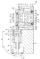
図1を参照して、電磁駆動弁10は、回転駆動式の電磁駆動弁であり、その運動機構に、平行リンク機構が採用されている。電磁駆動弁10は、一方向に延びるステム12を有する駆動弁14と、ステム12の異なる位置に連結され、作用された電磁力および弾性力によって揺動するロアディスク21およびアッパディスク31と、その電磁力を発生する開閉兼用電磁石60(以下、単に電磁石60とも呼ぶ)と、その弾性力を有するロアスプリング26およびアッパスプリング36とを備える。駆動弁14は、ロアディスク21およびアッパディスク31の揺動運動を受けて、ステム12が延びる方向(矢印103に示す方向)に往復運動する。
Referring to FIG. 1, an electromagnetically driven
駆動弁14は、吸気ポート17が形成されたシリンダヘッド41に搭載されている。シリンダヘッド41の吸気ポート17から図示しない燃焼室に連通する位置には、バルブシート42が設けられている。駆動弁14は、さらに、ステム12の先端に形成された傘部13を有する。駆動弁14の往復運動に伴って、傘部13がバルブシート42に密着したり、バルブシート42から離脱することによって、吸気ポート17の開閉が行なわれる。つまり、ステム12が上昇することによって駆動弁14が閉弁位置へと位置決めされ、ステム12が下降することによって、駆動弁14が開弁位置へと位置決めされる。
The
ステム12は、傘部13から連続する下部ステム12mと、ラッシュアジャスタ16を介して下部ステム12mに接続された上部ステム12nとから構成されている。ラッシュアジャスタ16は、上部ステム12nと下部ステム12mとの間で緩衝部材として機能し、縮みやすく伸び難い特性を有する。下部ステム12mには、その外周面から突出する連結ピン12pが形成されており、上部ステム12nには、その外周面から突出する連結ピン12qが、連結ピン12pから離れた位置で形成されている。
The
シリンダヘッド41には、下部ステム12mを軸方向に摺動可能なように案内するバルブガイド43が設けられており、バルブガイド43から離れた位置には、上部ステム12nを軸方向に摺動可能なように案内するステムガイド45が設けられている。バルブガイド43およびステムガイド45は、ステム12との高速摺動に耐えられるように、たとえば、ステンレスなどの金属材料から構成されている。
The
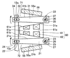
図2は、図1中のロアディスク(アッパディスク)を示す斜視図である。図1および図2を参照して、ロアディスク21は、一方端22と他方端23とを有し、一方端22から他方端23に向けて、ステム12に交差する方向に延びている。ロアディスク21は、一方端22を含む位置において、矩形形状の表面21a,21bを有する平板状に形成されている。ロアディスク21は、他方端23に位置して孔27が形成された中空円筒状に形成されている。ロアディスク21には、一方端22側に位置して、切欠き部28が形成されており、その切欠き部28の互いに向かい合う壁面には、長孔24が形成されている。
FIG. 2 is a perspective view showing the lower disk (upper disk) in FIG. With reference to FIGS. 1 and 2, the
アッパディスク31は、ロアディスク21と同様の形状を有し、ロアディスク21の一方端22、他方端23、表面21a、表面21b、孔27、切欠き部28および長孔24に対応して、一方端32、他方端33、表面31b、表面31a、孔37、切欠き部38および長孔34が形成されている。ロアディスク21およびアッパディスク31は、軟磁性材料から構成されている。
The
ロアディスク21の一方端22は、孔27に連結ピン12pが挿通されることによって、下部ステム12mに対して揺動自在(回動可能)に連結されている。アッパディスク31の一方端32は、孔37に連結ピン12qが挿通されることによって、上部ステム12nに対して揺動自在に連結されている。シリンダヘッド41の頂面上には、ステム12と平行に延びるディスクベース51が設けられている。ロアディスク21の他方端23は、ディスクベース51の支点25を中心に揺動自在に支持されており、アッパディスク31の他方端33は、ディスクベース51の支点35を中心に揺動自在に支持されている。このような構成により、ロアディスク21およびアッパディスク31を支点25,35をそれぞれ中心に揺動(回動)させることによって、駆動弁14を往復運動させることができる。
One
他方端23,33には、ロアスプリング26,アッパスプリング36がそれぞれ設けられている。ロアスプリング26により、ロアディスク21には、支点25を中心に時計回りの方向に付勢する弾性力が加えられている。アッパスプリング36により、アッパディスク31には、支点35を中心に反時計回りの方向に付勢する弾性力が加えられている。後に説明する電磁石60による電磁力が加わっていない状態で、ロアディスク21およびアッパディスク31は、ロアスプリング26およびアッパスプリング36によって開弁側の変位端と閉弁側の変位端との中間位置に位置決めされる。
Lower springs 26 and
図3は、図1中の電磁石を示す斜視図である。図1および図3を参照して、ディスクベース51には、ロアディスク21とアッパディスク31との間に位置するように電磁石60が設けられている。電磁石60は、開閉兼用コイル62と、磁性材料から形成され、アッパディスク31の表面31aおよびロアディスク21の表面21aにそれぞれ向かい合う吸着面61a,61bを有する開閉兼用コア61とから構成されている。開閉兼用コア61は、ロアディスク21またはアッパディスク31の一方端から他方端に向かう方向に延びる軸部61pを有する。開閉兼用コイル62は、軸部61pのまわりを旋回するように設けられており、モノコイルから構成されている。具体的には、開閉兼用コイル62は、複数の銅線を集合させた構成とされている。これに限られるものではなく、開閉兼用コイル62を構成する材料として、超電導線材を用いることも可能である。
FIG. 3 is a perspective view showing the electromagnet in FIG. Referring to FIGS. 1 and 3, an
ディスクベース51には、さらに、開弁用永久磁石55と、電磁石60を挟んで開弁用永久磁石55の反対側に位置する閉弁用永久磁石56とが設けられている。開弁用永久磁石55は、ロアディスク21の表面21bに向かい合う吸着面55aを有する。吸着面55aと電磁石60の吸着面61bとの間には、ロアディスク21が揺動する空間72が規定されている。また、閉弁用永久磁石56は、アッパディスク31の表面31bに向かい合う吸着面56aを有する。吸着面56aと電磁石60の吸着面61aとの間には、アッパディスク31が揺動する空間71が規定されている。
The
開閉兼用コア61には、複数本の溝361が設けられており、これらの溝に開閉兼用コイル62が嵌め合わせられている。図3では、1本のコイルを曲げることにより複数の溝361にコイルを嵌め合わせているが、この構成に限定されるものではなく複数本のコイルが溝に嵌め合わされていてもよい。すなわち、図3中の右側の溝には、あるコイルが巻付けられ、左側の溝には別のコイルが巻付けられていてもよい。さらに巻付け回数も特に制限されるものではない。
The open /
図4は、開弁側の変位端にあるアッパディスクおよびロアディスクを示す模式図である。図5は、中間位置にあるアッパディスクおよびロアディスクを示す模式図である。図6は、閉弁側の変位端にあるアッパディスクおよびロアディスクを示す模式図である。続いて、電磁駆動弁10の動作について説明を行なう。
FIG. 4 is a schematic diagram showing an upper disk and a lower disk at the displacement end on the valve opening side. FIG. 5 is a schematic diagram showing the upper disk and the lower disk at the intermediate position. FIG. 6 is a schematic diagram showing an upper disk and a lower disk at the displacement end on the valve closing side. Subsequently, the operation of the electromagnetically driven
図4を参照して、駆動弁14が開弁位置にある場合、開閉兼用コイル62には、開閉兼用コア61の軸部61pのまわりで矢印111に示す方向に電流が流れる。このとき、開閉兼用コア61に、矢印で示す方向に磁束が流れ、磁気回路63a,63b,63c,63dが発生する。つまり、アッパディスク31を電磁石60の吸着面61aに引き寄せる電磁力が発生する。一方、ロアディスク21は、開弁用永久磁石55によって、吸着面55aに引き寄せられている。結果、アッパディスク31およびロアディスク21は、支点25まわりに配置されたロアスプリング26の弾性力に抗して、図4中に示す開弁側の変位端に保たれている。
Referring to FIG. 4, when the
図5を参照して、次に開閉兼用コイル62への電流供給を停止すると、電磁石60に発生していた電磁力が消滅する。これにより、アッパディスク31およびロアディスク21は、ロアスプリング26の弾性力によって吸着面61a,55aからそれぞれ離脱し、中間位置に向けて揺動し始める。ロアスプリング26およびアッパスプリング36による弾性力は、アッパディスク31およびロアディスク21を中間位置に保持しようとする。このため、中間位置を越えた位置では、アッパスプリング36によってアッパディスク31およびロアディスク21に揺動方向と逆方向の力が作用する。しかし、アッパディスク31およびロアディスク21には、揺動する方向に沿って慣性力が作用しているため、アッパディスク31およびロアディスク21は、中間位置を越えた位置まで揺動する。
Referring to FIG. 5, when the current supply to the switching
図6を参照して、次にその中間位置を越えた位置において、再び開閉兼用コイル62に矢印111に示す方向に電流を流す。このとき、ロアディスク21が位置する側では、ロアディスク21が電磁石60に引き付けられる。一方、アッパディスク31は、閉弁用永久磁石56によって、吸着面56aに引き寄せられる。
Referring to FIG. 6, next, a current is passed again in the direction indicated by
なお、このとき、電磁石60で発生する電磁力によって、アッパディスク31も電磁石60の吸着面61aに引き寄せられる。しかし、電磁力は、互いの間隔が狭いロアディスク21と電磁石60との間でより大きく作用するため、アッパディスク31およびロアディスク21は、中間位置を越えた位置から図6中に示す閉弁側の変位端へと揺動する。
At this time, the
以降、開閉兼用コイル62への電流供給の開始と停止とを以上に説明したタイミングで繰返す。これにより、アッパディスク31およびロアディスク21を開弁側および閉弁側の変位端の間で揺動させ、この揺動運動を介して駆動弁14を往復運動させることが可能となる。
Thereafter, the start and stop of current supply to the open /
再度図1を参照して、シリンダヘッド41には、下部ステム12mを案内するためのバルブガイド43が設置されている。また、下部ステム12mはロアリテイナ46により保持され、ロアリテイナ46はロアスプリング86と接触している。これにより、ロアスプリング86がロアリテイナ46を上方向へ押し上げる。下部ステム12mにはラッシュアジャスタ16が取付けられる。ラッシュアジャスタ16を設けることによって、閉弁位置にある駆動弁14の位置決め誤差を吸収し、傘部13をバルブシート42に確実に密着させることができる。この実施の形態では、ロアディスク21およびアッパディスク31を同時に揺動させ、駆動弁14を往復運動させる平行リンク機構が採用されている。しかし、現実には、これらディスク部品間に生じる寸法誤差や組付け誤差から、駆動弁14の位置決めに誤差が生じやすい。このため、平行リンク機構を備える電磁駆動弁10では、ラッシュアジャスタ16を設けることが特に有効となる。
Referring to FIG. 1 again, the
実施の形態1に従った電磁駆動弁10は、電磁力と弾性力との協働により作動する電磁駆動弁であって、弁軸としてのステム12を有し、ステム12が延びる方向に沿って往復運動する駆動弁14と、ステム12に揺動自在に連結された一方端22,32と、ベース部材としてのディスクベース51に揺動自在に支持された他方端23,33とを有し、互いに間隔を隔てて設けられた第1および第2の揺動部材としてのロアディスク21およびアッパディスク31と、第1および第2のコイル161,162を有し、ロアディスク21とアッパディスク31との間に配置され、複数の磁気回路63a,63b,63c,63dを構成する電磁石60とを備える。第1および第2のコイル161,162に電流が流れることによって、ロアディスク21およびアッパディスク31に電磁力が作用する。
The electromagnetically driven
このように、本発明に従った電磁駆動弁10では、図4および図6で示すように、第1のコイル161および第2のコイル162が、それぞれのコイルのまわりにおいて磁気回路63a,63b,63c,63dを発生させる。磁気回路63a,63bは第1のコイル161によって生じ、磁気回路63c,63dは、第2のコイル162によって生じる。このように、複数のコイルを用いて複数の磁気回路を発生させれば、それぞれの磁気回路がアッパディスク31を引き付ける。このため、引き付け力がアッパディスク31に均等に加わるため、アッパディスク31の厚みを薄くしても、アッパディスク31が破損することがない。同様に、ロアディスク21は、複数の磁気回路63b,63dに引き付けられるため、ロアディスク21は均一な力で電磁石60に引き付けられる。その結果、ロアディスク21の厚みを薄くしたとしても、ロアディスク21が破損することがない。その結果、ロアディスク21およびアッパディスク31の質量を小さくすることができ、可動部分の軽量化を図ることができる。これにより、消費電力の低減の効果を達成することができる。
Thus, in the electromagnetically driven
この発明では、電磁駆動弁のアクチュエータに平行リンク機構を採用した構造において、コイルを2個以上縦置きに配置することにより、磁気回路をコイルの個数の2倍設けることができ、これにより電磁力が大きくなる。 In the present invention, in a structure in which a parallel link mechanism is employed for the actuator of the electromagnetically driven valve, by arranging two or more coils vertically, the magnetic circuit can be provided twice as many as the number of coils. Becomes larger.
(実施の形態2)
図7は、この発明の実施の形態2に従った電磁石の断面図である。実施の形態2では、ターン数が各々違う2個以上のコイルを配置し、電力応答性の向上および駆動時の電磁力アップを両立させ、作動安定性、消費電力の低減を両立する。すなわち、実施の形態2では、図7で示すように、ターン数が少ない第1のコイル161と、ターン数が多い第2のコイル162とを設ける。第2のコイル162が支点25,35に近い側に位置し、第1のコイル161が支点25,35から遠い側に位置する。第1のコイル161と第2のコイル162とは別々の回路に接続され、それぞれ独立して電流を制御することが可能である。第1および第2のコイル以外のコイルが存在していてもよく、そのコイルの巻き数、配置は制限されない。
(Embodiment 2)
FIG. 7 is a cross-sectional view of an electromagnet according to Embodiment 2 of the present invention. In the second embodiment, two or more coils each having a different number of turns are arranged to achieve both improvement in power response and increase in electromagnetic force during driving, thereby achieving both operational stability and reduction in power consumption. That is, in the second embodiment, as shown in FIG. 7, a
電磁力と電磁力応答性の関係は相反する関係となる。すなわち、コイルのターン数が大きければ電磁力が大きくなるが電磁力応答性は悪化する。これに対して、コイルのターン数が小さければ電磁力の応答性は改善するものの、電磁力が小さくなる。このように相反する特性を両立させるべく、実施の形態2では、電磁力が大きく作用する、支点25,35より遠い側の第1のコイル161では、制御性の向上を狙い、ターン数を少なくし、電磁力の応答性を向上させる。これに対して、支点25,35に近い側の第2のコイル162では、ギャップが大きいときの電磁力を大きくすることを目的とし、コイルのターン数を多くし、電磁力を向上させる。
The relationship between electromagnetic force and electromagnetic force responsiveness is a contradictory relationship. That is, if the number of turns of the coil is large, the electromagnetic force is increased, but the electromagnetic force response is deteriorated. On the other hand, if the number of turns of the coil is small, the response of the electromagnetic force is improved, but the electromagnetic force is reduced. In order to make the contradictory characteristics compatible with each other, in the second embodiment, the
このように構成された、実施の形態2に従った電磁駆動弁でも、実施の形態1に従った電磁駆動弁と同様の効果がある。 The electromagnetically driven valve according to the second embodiment configured as described above has the same effect as the electromagnetically driven valve according to the first embodiment.
(実施の形態3)
図8は、この発明の実施の形態3に従った電磁石の断面図である。図9は、比較例の回路構成を示す図である。図10は、実施の形態3に従った回路構成を示す図である。
(Embodiment 3)
FIG. 8 is a cross-sectional view of an electromagnet according to Embodiment 3 of the present invention. FIG. 9 is a diagram illustrating a circuit configuration of a comparative example. FIG. 10 shows a circuit configuration according to the third embodiment.
図8および図10を参照して、この発明の実施の形態3に従った電磁石60においては、ターン数が各々違う2個以上のコイルを直列に接続することによりコイルをモノコイル化し、電力応答性の向上および駆動時の電磁力の向上を両立し、作動安定性、消費電力の低減、駆動回路の低コスト化を図る。具体的には、図8で示すように、各コイルの巻き始めもしくは終わりの片側たとえば図8の点Aと点Cをつなぐ。もしくは、巻線時に連続的に2個以上のコイルを巻くことにより、2個以上のコイルをモノコイル化する。これにより、電磁力および電力応答性を考慮したターン数に設定すると実施の形態2で示した効果がモノコイルにより実現できる。また、回路素子の個数を減らすことが可能であり、回路を簡素化、低コスト化することができる。
Referring to FIGS. 8 and 10, in
具体的には、図9で示すように、第1のコイル161および第2のコイル162を並列的に接続すれば、その動作を制御するためのトランジスタ(電界効果型トランジスタ)201から208の8つのトランジスタが必要となる。これに対し、図10で示すように、モノコイル化することによって、4つのトランジスタによりこれらのコイルの動作を制御することが可能である。すなわち、1つの電磁石を駆動させる際のトランジスタが1/2に低減でき、その結果、トランジスタの費用が1/2に低減することができる。これにより、大幅な低コスト化が可能となる。
Specifically, as shown in FIG. 9, if the
(実施の形態4)
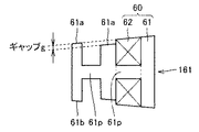
図11は、この発明の実施の形態4に従った電磁石の断面図である。実施の形態4に従った電磁石では、磁気回路のバイパスを設けることにより駆動時の電流を低減し、消費電力を低減することができる。図11で示すように、開閉兼用コア61の吸着面61aにはギャップgが設けられている。すなわち、中央部に位置する吸着面61aの高さが他の部分に比べて低くなっている。
(Embodiment 4)
FIG. 11 is a cross-sectional view of an electromagnet according to Embodiment 4 of the present invention. In the electromagnet according to the fourth embodiment, by providing a bypass of the magnetic circuit, the current during driving can be reduced and the power consumption can be reduced. As shown in FIG. 11, a gap g is provided on the
図12および図13は、この発明の実施の形態4に従った電磁石の動作を説明するための断面図である。図12で示すように、中立時には、外側の吸着面61aと表面31aとの距離はL1となり、中央の吸着面61aと表面31aとの間の距離はL2となり、L2はL1より小さい。そのため、距離L2の部分を通るように磁気回路163aが生じる。磁気回路163aの中心を通るように矢印164で示すように電磁力がアッパディスク31に加わる。
12 and 13 are sectional views for illustrating the operation of the electromagnet according to the fourth embodiment of the present invention. As shown in FIG. 12, when neutral, the distance between the
図13で示すように開弁時にはアッパディスク31が開閉兼用コア61側へ近づく。これにより、外側の吸着面61aが表面31aに接触する。この状態では、大きな磁気回路163bが発生し、その中心を通るように矢印165で示すように電磁力が発生する。
As shown in FIG. 13, when the valve is opened, the
すなわち、この実施の形態では、開閉兼用コア61に磁気バイパスを設ける。実施の形態4では、第1のコイル161が第1および第2の磁気回路としての磁気回路163a,163bを構成する。
これにより、図12で示す中立時では、アッパディスク31とのギャップが小さい支点35近傍で電磁力が発生し、引き付け力として働く。開弁および閉弁時には、バイパス側に磁束が流れレバー比が大きくなった状態で保持できる。これにより、電流を低減でき、消費電力を低減できる。
That is, in this embodiment, a magnetic bypass is provided in the open /
Thereby, at the neutral time shown in FIG. 12, an electromagnetic force is generated in the vicinity of the fulcrum 35 where the gap with the
(実施の形態5)
図14は、この発明の実施の形態5に従った電磁駆動弁の断面図である。図14を参照して、この発明の実施の形態5に従った電磁駆動弁10では、バルブの中心軸213がオフセット配置されることで、レバー比が最適化される。具体的には第1のコイル161の中心軸260と他方端23,33との間に中心軸213を設ける。支点25,35から中心軸213までの距離はLv、第1のコイル161の中心軸260から支点25,35までの距離はLe、上部ステム12nから支点25,35までの距離はLsである。このとき、バルブで必要とされる力Fvと電磁力Feの関係は以下のとおりである。
(Embodiment 5)
FIG. 14 is a cross-sectional view of an electromagnetically driven valve according to Embodiment 5 of the present invention. Referring to FIG. 14, in the electromagnetically driven
Fv×Lv<Fe×Le
この式は以下のように変形できる。
Fv × Lv <Fe × Le
This equation can be modified as follows.
Fe>Fv×(Lv/Le)
なお、永久磁石による影響は省略している。つまり、Lv<Leの関係となるようにバルブ位置を調整すると、必要な電磁力Feは小さくなる。これにより、電磁力Feを発生させるための電流を低減することが可能となり、消費電力を低減することができる。
Fe> Fv × (Lv / Le)
In addition, the influence by a permanent magnet is abbreviate | omitted. That is, if the valve position is adjusted so that Lv <Le, the required electromagnetic force Fe is reduced. Thereby, it becomes possible to reduce the electric current for generating the electromagnetic force Fe, and to reduce power consumption.
なお、この実施の形態では、第1のコイル161のみを用いる構造を示したが、これに限られるものではなく、第1のコイル161と第2のコイル162とを用いてもよい。
In this embodiment, the structure using only the
この実施の形態に従った電磁駆動弁は、電磁力と弾性力との協働により作動する電磁駆動弁10であって、弁軸としての下部ステム12mを有し、下部ステム12mが延びる方向に沿って往復運動する駆動弁14と、ディスクベース51に揺動自在に支持される端部を有し、互いに距離を隔てて設けられて互いに対応して揺動する第1および第2の揺動部材としてのロアディスク21およびアッパディスク31と、第1のコイル161を有し、ロアディスク21とアッパディスク31との間に配置される電磁石60とを有する。第1のコイル161に電流が流れることによってロアディスク21およびアッパディスク31に電磁力が作用し、中心軸213は、電磁石による電磁力の中心軸260と他方端23,33との間に位置する。
The electromagnetically driven valve according to this embodiment is an electromagnetically driven
(実施の形態6)
図15は、この発明の実施の形態6に従った電磁駆動弁の断面図である。図15を参照して、この発明の実施の形態6に従った電磁駆動弁10では、ステム12がフレキシブルアームで構成されている。すなわち、2枚のディスクを連結する部位にフレキシブルなアームを用いることで、アッパディスク31およびロアディスク21の各々がギャップがなくなる位置まで動くことができ、大きな力を発生させることができ、これにより消費電力を低減させる。
(Embodiment 6)
FIG. 15 is a sectional view of an electromagnetically driven valve according to
具体的には、上部ステム12nが剛体の場合、ロアディスク21およびアッパディスク31を上部ステム12nで接続するとアッパディスク31およびロアディスク21は電磁石60または開弁用永久磁石55または閉弁用永久磁石56のどちらか片方にしか当たらない状態となる。そのとき、当たらなかった側ではギャップが発生し、電磁力を最大限に発揮させることができない。そこで、本発明では図15で示すように、上部ステム12nを上下方向にフレキシブルなアーム(若干の伸び縮みができるアーム)で構成することにより、アッパディスク31およびロアディスク21が相手部材に確実に接触する位置まで移動することができ、電磁力を最大限まで発揮させることが可能となる。
Specifically, when the
これにより、これまでの必要最低限の電流で電磁力を発生させることができ、消費電力を低減させることができる。 As a result, electromagnetic force can be generated with the necessary minimum current so far, and power consumption can be reduced.
この発明に従った電磁駆動弁は、電磁力と弾性力との協働により作動する電磁駆動弁10であって、伸縮可能な弁軸としてのステム12を有し、ステム12が延びる方向に沿って往復運動する駆動弁14と、ステム12に揺動自在に連結された一方端22,32と、ベース部材としてのディスクベース51に揺動自在に支持された他方端23,33とを有し、互いに間隔を隔てて設けられた第1および第2の揺動部材としてのロアディスク21およびアッパディスク31と、第1および第2のコイル161,162を有し、ロアディスク21とアッパディスク31との間に配置される電磁石60とを備える。第1および第2のコイル161,162に電流が流れることによって、第1および第2の揺動部材としてのロアディスク21およびアッパディスク31に電磁力が作用する。
The electromagnetically driven valve according to the present invention is an electromagnetically driven
上部ステム12nはフレキシブルアームにより構成され、その往復方向に若干の伸縮が可能となる。
The
図16から図20は、ステムの例を示す図である。図16を参照して、ステム12が上部ステム12nと下部ステム12mとに分割され、その間にスプリング112が設けられていてもよい。スプリング112は上部ステム12nおよび下部ステム12mを接続し、かつ上部ステム12nおよび下部ステム12mの間の距離を調整することが可能である。上部ステム12nおよび下部ステム12mはともに金属材料で構成され、上部ステム12nはアッパディスク31と接続され、下部ステム12mはロアディスク21と接続される。スプリング112に代えて、ラッシュアジャスタなどまたは弾性体を挿入してもよい。
16 to 20 are diagrams showing examples of stems. Referring to FIG. 16, the
図17を参照して、上部ステム12nおよび下部ステム12mの間にゴム、樹脂などの弾性体またはダンパなどを挿入してもよい。この収縮体113は圧縮力に対して縮むことが可能である。なお、上部ステム12nおよび下部ステム12mは、上記と同様にアッパディスク31およびロアディスク21に接続される。弾性体部材である収縮体113はゴムなどにより構成できる。また、ダンパを用いてもよい。
Referring to FIG. 17, an elastic body such as rubber or resin or a damper may be inserted between
図18を参照して、ステム12を中空の筒形状とし、その中にコイル312を嵌め合わせてもよい。コイル312のばね定数により剛性を設定する。コイル312の一方端はアッパディスクと接続され、他方端はロアディスクと接続される。
Referring to FIG. 18, the
図19で示すように、上部ステム12nと下部ステム12mとを分割し、クリアランスを設けてもよい。その周囲には上下ステムの位置合わせガイドを設ける。さらに、上部ステム12nと下部ステム12mが図20で示すように折れ曲がる構造としてもよい。
As shown in FIG. 19, the
今回開示された実施の形態はすべての点で例示であって制限的なものではないと考えられるべきである。本発明の範囲は上記した説明ではなくて特許請求の範囲によって示され、特許請求の範囲と均等の意味および範囲内でのすべての変更が含まれることが意図される。 The embodiment disclosed this time should be considered as illustrative in all points and not restrictive. The scope of the present invention is defined by the terms of the claims, rather than the description above, and is intended to include any modifications within the scope and meaning equivalent to the terms of the claims.
この発明は、車両に搭載される電磁駆動弁の分野において用いることができる。 The present invention can be used in the field of electromagnetically driven valves mounted on vehicles.
10 電磁駆動弁、14 駆動弁、 21 ロアスプリング、22,32 一方端、 23,33 他方端、31 ロアスプリング、60 電磁石。 10 Electromagnetic drive valve, 14 Drive valve, 21 Lower spring, 22, 32 One end, 23, 33 The other end, 31 Lower spring, 60 Electromagnet.
Claims (7)
弁軸を有し、前記弁軸が延びる方向に沿って往復運動する駆動弁と、
前記弁軸に揺動自在に連結された一方端と、ベース部材に揺動自在に支持された他方端とを有し、互いに間隔を隔てて設けられた第1および第2の揺動部材と、
コイルを有し、前記第1の揺動部材と前記第2の揺動部材との間に配置され、複数の磁気回路を構成する電磁石とを備え、
前記コイルに電流が流れることによって前記第1および第2の揺動部材に前記電磁力が作用する、電磁駆動弁。 An electromagnetically driven valve that operates in cooperation with electromagnetic force and elastic force,
A drive valve having a valve shaft and reciprocating along a direction in which the valve shaft extends;
First and second swinging members having one end pivotably connected to the valve shaft and the other end swingably supported by the base member and spaced apart from each other; ,
An electromagnet having a coil and disposed between the first rocking member and the second rocking member and constituting a plurality of magnetic circuits;
An electromagnetically driven valve in which the electromagnetic force acts on the first and second oscillating members when a current flows through the coil.
弁軸を有し、前記弁軸が延びる方向に沿って往復運動する駆動弁と、
前記弁軸に揺動自在に連結された一方端と、ベース部材に揺動自在に支持された他方端とを有し、互いに間隔を隔てて設けられた第1および第2の揺動部材と、
コイルを有し、前記第1の揺動部材と前記第2の揺動部材との間に配置される電磁石とを備え、
前記コイルに電流が流れることによって、前記第1および第2の揺動部材に電磁力が作用し、前記弁軸は電磁石による電磁力の中心軸と他方端との間に位置する、電磁駆動弁。 An electromagnetically driven valve that operates in cooperation with electromagnetic force and elastic force,
A drive valve having a valve shaft and reciprocating along a direction in which the valve shaft extends;
First and second swinging members having one end pivotably connected to the valve shaft and the other end swingably supported by the base member and spaced apart from each other; ,
An electromagnet having a coil and disposed between the first rocking member and the second rocking member;
When an electric current flows through the coil, an electromagnetic force acts on the first and second oscillating members, and the valve shaft is located between the central axis of the electromagnetic force by the electromagnet and the other end. .
弁軸を有し、前記弁軸が延びる方向に沿って往復運動する伸縮可能な駆動弁と、
前記弁軸に揺動自在に連結された一方端と、ベース部材に揺動自在に支持された他方端とを有し、互いに間隔を隔てて設けられた第1および第2の揺動部材と、
コイルを有し、前記第1の揺動部材と前記第2の揺動部材との間に配置される電磁石とを備え、
前記コイルに電流が流れることによって、前記第1および第2の揺動部材に前記電磁力が作用する、電磁駆動弁。 An electromagnetically driven valve that operates in cooperation with electromagnetic force and elastic force,
A retractable drive valve having a valve shaft and reciprocating along a direction in which the valve shaft extends;
First and second swinging members having one end pivotably connected to the valve shaft and the other end swingably supported by the base member and spaced apart from each other; ,
An electromagnet having a coil and disposed between the first rocking member and the second rocking member;
An electromagnetically driven valve in which the electromagnetic force acts on the first and second oscillating members when a current flows through the coil.
Priority Applications (6)
| Application Number | Priority Date | Filing Date | Title |
|---|---|---|---|
| JP2004239777A JP2006057521A (en) | 2004-08-19 | 2004-08-19 | Solenoid drive valve |
| US11/660,382 US20070284551A1 (en) | 2004-08-19 | 2005-06-22 | Electromagnetically Driven Valve |
| CNA2005800276650A CN101061292A (en) | 2004-08-19 | 2005-06-22 | Electromagnetically driven valve |
| DE602005009723T DE602005009723D1 (en) | 2004-08-19 | 2005-06-22 | ELECTROMAGNETICALLY GEARED VALVE |
| EP05780106A EP1789659B1 (en) | 2004-08-19 | 2005-06-22 | Electromagnetically driven valve |
| PCT/JP2005/011895 WO2006018931A1 (en) | 2004-08-19 | 2005-06-22 | Electromagnetically driven valve |
Applications Claiming Priority (1)
| Application Number | Priority Date | Filing Date | Title |
|---|---|---|---|
| JP2004239777A JP2006057521A (en) | 2004-08-19 | 2004-08-19 | Solenoid drive valve |
Publications (2)
| Publication Number | Publication Date |
|---|---|
| JP2006057521A true JP2006057521A (en) | 2006-03-02 |
| JP2006057521A5 JP2006057521A5 (en) | 2006-12-28 |
Family
ID=35044536
Family Applications (1)
| Application Number | Title | Priority Date | Filing Date |
|---|---|---|---|
| JP2004239777A Pending JP2006057521A (en) | 2004-08-19 | 2004-08-19 | Solenoid drive valve |
Country Status (6)
| Country | Link |
|---|---|
| US (1) | US20070284551A1 (en) |
| EP (1) | EP1789659B1 (en) |
| JP (1) | JP2006057521A (en) |
| CN (1) | CN101061292A (en) |
| DE (1) | DE602005009723D1 (en) |
| WO (1) | WO2006018931A1 (en) |
Families Citing this family (7)
| Publication number | Priority date | Publication date | Assignee | Title |
|---|---|---|---|---|
| JP4475198B2 (en) | 2005-07-27 | 2010-06-09 | トヨタ自動車株式会社 | Solenoid valve |
| JP2007040162A (en) | 2005-08-02 | 2007-02-15 | Toyota Motor Corp | Electromagnetic driving valve |
| EP1749983A3 (en) | 2005-08-02 | 2008-01-16 | Toyota Jidosha Kabushiki Kaisha | Electromagnetically driven valve |
| JP2007040238A (en) | 2005-08-04 | 2007-02-15 | Toyota Motor Corp | Electromagnetic driving valve |
| JP2007046498A (en) | 2005-08-08 | 2007-02-22 | Toyota Motor Corp | Solenoid-driven valve |
| JP2007046503A (en) | 2005-08-08 | 2007-02-22 | Toyota Motor Corp | Solenoid-driven valve |
| DE202006006825U1 (en) * | 2006-04-27 | 2007-08-30 | Bürkert Werke GmbH & Co. KG | Valve with an electromagnetic drive |
Family Cites Families (12)
| Publication number | Priority date | Publication date | Assignee | Title |
|---|---|---|---|---|
| EP0796402B1 (en) * | 1994-11-09 | 2000-05-31 | Aura Systems, Inc. | Hinged armature electromagnetically actuated valve |
| US5765513A (en) * | 1996-11-12 | 1998-06-16 | Ford Global Technologies, Inc. | Electromechanically actuated valve |
| US6262498B1 (en) * | 1997-03-24 | 2001-07-17 | Heinz Leiber | Electromagnetic drive mechanism |
| DE19955054A1 (en) * | 1998-11-16 | 2000-08-17 | Heinz Leiber | Electromagnetic actuator with torsion spring connected to lever by tube and extending partly into tube |
| DE19860451A1 (en) * | 1998-12-28 | 2000-06-29 | Heinz Leiber | Actuator for a valve of an internal combustion engine |
| IT1310502B1 (en) * | 1999-09-30 | 2002-02-18 | Magneti Marelli Spa | ELECTROMAGNETIC ACTUATOR OF THE PERFECT TYPE FOR THE VALVE CONTROL OF A COMBUSTION ENGINE. |
| ITBO20000293A1 (en) * | 2000-05-16 | 2001-11-16 | Magneti Marelli Spa | METHOD FOR THE PROTECTION OF ELECTROMAGNETIC ACTUATORS FROM OVERHEATING FOR INTAKE AND EXHAUST VALVES IN MOTORS |
| ITBO20000366A1 (en) * | 2000-06-23 | 2001-12-23 | Magneti Marelli Spa | ELECTROMAGNETIC ACTUATOR FOR THE OPERATION OF THE VALVES OF A COMBUSTION ENGINE. |
| JP2002122264A (en) * | 2000-10-12 | 2002-04-26 | Toyota Motor Corp | Electromagnetically driven valve |
| KR100401645B1 (en) * | 2001-08-21 | 2003-10-17 | 현대자동차주식회사 | Electro-mechanical balve train |
| DE60108767T2 (en) * | 2001-12-04 | 2005-09-22 | Ford Global Technologies, LLC (n.d.Ges.d. Staates Delaware), Dearborn | Electromagnetic valve actuator with permanent magnet support |
| US6763789B1 (en) * | 2003-04-01 | 2004-07-20 | Ford Global Technologies, Llc | Electromagnetic actuator with permanent magnet |
-
2004
- 2004-08-19 JP JP2004239777A patent/JP2006057521A/en active Pending
-
2005
- 2005-06-22 CN CNA2005800276650A patent/CN101061292A/en active Pending
- 2005-06-22 US US11/660,382 patent/US20070284551A1/en not_active Abandoned
- 2005-06-22 EP EP05780106A patent/EP1789659B1/en not_active Not-in-force
- 2005-06-22 WO PCT/JP2005/011895 patent/WO2006018931A1/en active IP Right Grant
- 2005-06-22 DE DE602005009723T patent/DE602005009723D1/en not_active Expired - Fee Related
Also Published As
| Publication number | Publication date |
|---|---|
| WO2006018931A1 (en) | 2006-02-23 |
| EP1789659A1 (en) | 2007-05-30 |
| EP1789659B1 (en) | 2008-09-10 |
| CN101061292A (en) | 2007-10-24 |
| US20070284551A1 (en) | 2007-12-13 |
| DE602005009723D1 (en) | 2008-10-23 |
Similar Documents
| Publication | Publication Date | Title |
|---|---|---|
| EP1464796B1 (en) | Electromagnetic valve actuator with permanent magnet for an internal combustion engine | |
| US7418932B2 (en) | Electromagnetically driven valve | |
| EP1789659B1 (en) | Electromagnetically driven valve | |
| JP4155243B2 (en) | Solenoid valve | |
| US20070221873A1 (en) | Electromagnetically Driven Valve | |
| JP2006336525A (en) | Electromagnetic actuation valve | |
| JP2002115515A (en) | Actuator for solenoid driving valve and valve system of internal combustion engine and electromagnetically driving method of valve element | |
| US20070290156A1 (en) | Electromagnetically Driven Valve | |
| JP4475198B2 (en) | Solenoid valve | |
| JP4124183B2 (en) | Electromagnetically driven valve and control method thereof | |
| JP4691009B2 (en) | Solenoid valve device for engine | |
| JP5025195B2 (en) | Solenoid valve device for engine | |
| EP1784559A1 (en) | Electromagnetically driven valve | |
| JP2006336737A (en) | Solenoid actuated valve | |
| JP4140596B2 (en) | Electromagnetically driven valve and internal combustion engine | |
| JP2007040162A (en) | Electromagnetic driving valve | |
| JP2006104981A (en) | Solenoid driving valve and internal combustion engine | |
| JP2008202427A (en) | Solenoid valve | |
| JPH11173126A (en) | Solenoid valve driving device | |
| US20100059003A1 (en) | Engine electromagnetic valve operating device | |
| JP2008180140A (en) | Solenoid-driven valve | |
| JP2007170466A (en) | Solenoid driven valve | |
| JP2007046497A (en) | Solenoid-driven valve | |
| JP2007064474A (en) | Electromagnetic drive valve | |
| JP2007154714A (en) | Solenoid valve |
Legal Events
| Date | Code | Title | Description |
|---|---|---|---|
| A521 | Request for written amendment filed |
Free format text: JAPANESE INTERMEDIATE CODE: A523 Effective date: 20061114 |
|
| A621 | Written request for application examination |
Free format text: JAPANESE INTERMEDIATE CODE: A621 Effective date: 20061114 |
|
| A131 | Notification of reasons for refusal |
Free format text: JAPANESE INTERMEDIATE CODE: A131 Effective date: 20080617 |
|
| A521 | Request for written amendment filed |
Free format text: JAPANESE INTERMEDIATE CODE: A523 Effective date: 20080814 |
|
| A131 | Notification of reasons for refusal |
Free format text: JAPANESE INTERMEDIATE CODE: A131 Effective date: 20090120 |
|
| A02 | Decision of refusal |
Free format text: JAPANESE INTERMEDIATE CODE: A02 Effective date: 20090526 |