JP2006506778A - Liquid-cooled fuel cell stack - Google Patents
Liquid-cooled fuel cell stack Download PDFInfo
- Publication number
- JP2006506778A JP2006506778A JP2004551453A JP2004551453A JP2006506778A JP 2006506778 A JP2006506778 A JP 2006506778A JP 2004551453 A JP2004551453 A JP 2004551453A JP 2004551453 A JP2004551453 A JP 2004551453A JP 2006506778 A JP2006506778 A JP 2006506778A
- Authority
- JP
- Japan
- Prior art keywords
- fuel cell
- cooling
- cell stack
- cooling channel
- manifold
- Prior art date
- Legal status (The legal status is an assumption and is not a legal conclusion. Google has not performed a legal analysis and makes no representation as to the accuracy of the status listed.)
- Pending
Links
Images


Classifications
-
- H—ELECTRICITY
- H01—ELECTRIC ELEMENTS
- H01M—PROCESSES OR MEANS, e.g. BATTERIES, FOR THE DIRECT CONVERSION OF CHEMICAL ENERGY INTO ELECTRICAL ENERGY
- H01M8/00—Fuel cells; Manufacture thereof
- H01M8/24—Grouping of fuel cells, e.g. stacking of fuel cells
-
- H—ELECTRICITY
- H01—ELECTRIC ELEMENTS
- H01M—PROCESSES OR MEANS, e.g. BATTERIES, FOR THE DIRECT CONVERSION OF CHEMICAL ENERGY INTO ELECTRICAL ENERGY
- H01M8/00—Fuel cells; Manufacture thereof
- H01M8/04—Auxiliary arrangements, e.g. for control of pressure or for circulation of fluids
- H01M8/04007—Auxiliary arrangements, e.g. for control of pressure or for circulation of fluids related to heat exchange
- H01M8/04067—Heat exchange or temperature measuring elements, thermal insulation, e.g. heat pipes, heat pumps, fins
-
- H—ELECTRICITY
- H01—ELECTRIC ELEMENTS
- H01M—PROCESSES OR MEANS, e.g. BATTERIES, FOR THE DIRECT CONVERSION OF CHEMICAL ENERGY INTO ELECTRICAL ENERGY
- H01M8/00—Fuel cells; Manufacture thereof
- H01M8/04—Auxiliary arrangements, e.g. for control of pressure or for circulation of fluids
-
- H—ELECTRICITY
- H01—ELECTRIC ELEMENTS
- H01M—PROCESSES OR MEANS, e.g. BATTERIES, FOR THE DIRECT CONVERSION OF CHEMICAL ENERGY INTO ELECTRICAL ENERGY
- H01M8/00—Fuel cells; Manufacture thereof
- H01M8/04—Auxiliary arrangements, e.g. for control of pressure or for circulation of fluids
- H01M8/04007—Auxiliary arrangements, e.g. for control of pressure or for circulation of fluids related to heat exchange
- H01M8/04029—Heat exchange using liquids
-
- H—ELECTRICITY
- H01—ELECTRIC ELEMENTS
- H01M—PROCESSES OR MEANS, e.g. BATTERIES, FOR THE DIRECT CONVERSION OF CHEMICAL ENERGY INTO ELECTRICAL ENERGY
- H01M8/00—Fuel cells; Manufacture thereof
- H01M8/24—Grouping of fuel cells, e.g. stacking of fuel cells
- H01M8/2465—Details of groupings of fuel cells
- H01M8/247—Arrangements for tightening a stack, for accommodation of a stack in a tank or for assembling different tanks
- H01M8/248—Means for compression of the fuel cell stacks
-
- H—ELECTRICITY
- H01—ELECTRIC ELEMENTS
- H01M—PROCESSES OR MEANS, e.g. BATTERIES, FOR THE DIRECT CONVERSION OF CHEMICAL ENERGY INTO ELECTRICAL ENERGY
- H01M8/00—Fuel cells; Manufacture thereof
- H01M8/10—Fuel cells with solid electrolytes
- H01M2008/1095—Fuel cells with polymeric electrolytes
-
- Y—GENERAL TAGGING OF NEW TECHNOLOGICAL DEVELOPMENTS; GENERAL TAGGING OF CROSS-SECTIONAL TECHNOLOGIES SPANNING OVER SEVERAL SECTIONS OF THE IPC; TECHNICAL SUBJECTS COVERED BY FORMER USPC CROSS-REFERENCE ART COLLECTIONS [XRACs] AND DIGESTS
- Y02—TECHNOLOGIES OR APPLICATIONS FOR MITIGATION OR ADAPTATION AGAINST CLIMATE CHANGE
- Y02E—REDUCTION OF GREENHOUSE GAS [GHG] EMISSIONS, RELATED TO ENERGY GENERATION, TRANSMISSION OR DISTRIBUTION
- Y02E60/00—Enabling technologies; Technologies with a potential or indirect contribution to GHG emissions mitigation
- Y02E60/30—Hydrogen technology
- Y02E60/50—Fuel cells
Abstract
Description
本発明は、エネルギー省によって認められた協力協定DE−FC02−99EE50582に基づき政府の援助でなされた。政府は、本発明における特定の権利を有する。 This invention was made with government support under the cooperation agreement DE-FC02-99EE50582 approved by the Ministry of Energy. The government has certain rights in the invention.
本発明は、スタック全体にわたって冷却されかつ均一に温度管理される、液体冷却式燃料電池スタックに関する。 The present invention relates to a liquid cooled fuel cell stack that is cooled and uniformly temperature controlled throughout the stack.
当該技術において説明されておらず、かつ本発明によって提供されるのは、均一な冷却剤流、冷却剤向流、および外部絶縁をもたらすことによって、燃料電池スタック全体にわたって冷却し実質的に均一な温度を維持する装置である。 Not described in the art, and provided by the present invention provides cooling and substantially uniform cooling throughout the fuel cell stack by providing uniform coolant flow, coolant counter-current, and external insulation. It is a device that maintains the temperature.
簡単に言えば、本発明は、1つ以上の膜電極アセンブリ(MEA)を含む燃料電池モジュールと、冷却チャネルを含む冷却プレートと、各冷却チャネル入口と連通するマニホルドボックスと、冷却チャネル入口に対して一様に分配された複数のディフューザ出口を有する、マニホルドボックス内のディフューザとを含む、液体冷却式燃料電池スタックを提供する。典型的には、2チャンバマニホルドボックスを使用して、スタックの互いに反対側の冷却チャネル内の互いに反対方向の冷却剤の向流を可能にする。典型的には、スタックは、その外側の周りで絶縁される。 Briefly, the present invention relates to a fuel cell module that includes one or more membrane electrode assemblies (MEAs), a cooling plate that includes cooling channels, a manifold box that communicates with each cooling channel inlet, and a cooling channel inlet. And a diffuser in a manifold box having a plurality of uniformly distributed diffuser outlets. Typically, a two-chamber manifold box is used to allow counter-flow of coolant in opposite directions in cooling channels on opposite sides of the stack. Typically, the stack is insulated around its outside.
本発明の利点は、燃料電池スタックの冷却をもたらし、一方、スタック全体にわたって実質的に均一な温度を維持することである。 An advantage of the present invention is that it provides cooling of the fuel cell stack while maintaining a substantially uniform temperature throughout the stack.
燃料電池スタックの動作は、3つの寸法で延びた大きいブロックの形態をとり、かつ、全体にわたってかなりの熱を発生し、一方、ブロック全体にわたって均一な温度を維持する1つの電力発生設備を冷却するという問題を提示する。 The operation of the fuel cell stack takes the form of a large block extending in three dimensions and generates a significant amount of heat throughout, while cooling a single power generation facility that maintains a uniform temperature throughout the block. Presents the problem.
本発明は、1つ以上の膜電極アセンブリ(MEA)を含む燃料電池モジュールと、冷却チャネルを含む冷却プレートと、各冷却チャネル入口と連通するマニホルドボックスと、典型的には、冷却チャネル入口に対して一様に分配された複数のディフューザ出口を有する、マニホルドボックス内のディフューザとを含む、液体冷却式燃料電池スタックを提供する。典型的には、2チャンバマニホルドボックスを使用して、スタックの互いに反対側の冷却チャネル内の互いに反対方向の冷却剤の向流を可能にする。典型的には、スタックは、その外側の周りで絶縁される。 The present invention relates to a fuel cell module that includes one or more membrane electrode assemblies (MEAs), a cooling plate that includes cooling channels, a manifold box that communicates with each cooling channel inlet, and typically to the cooling channel inlet. And a diffuser in a manifold box having a plurality of uniformly distributed diffuser outlets. Typically, a two-chamber manifold box is used to allow counter-flow of coolant in opposite directions in cooling channels on opposite sides of the stack. Typically, the stack is insulated around its outside.
燃料電池は、水素などの燃料、および酸素などの酸化剤を使用して、電流を発生する。2つの化学反応物、すなわち、燃料および酸化剤は、触媒を含有する2つの絶縁された電極で別々に反応する。2つの反応物の直接化学反応を防止し、イオンを伝導するために、イオン交換要素が電極間に配置される。典型的な水素燃料電池の場合、イオン交換要素はイオン伝導膜(ICM)である。ICMは、水素電極から酸素電極にプロトン(H+)を伝導する。電子が別個の外部電気経路に従い、それにより、電流を発生する。ICMと電極との組合せは、一般に、「膜電極アセンブリ」すなわちMEAと呼ばれる。触媒電極材料をICM上に直接コーティングして触媒コーティング膜(CCM)を形成してもよい。典型的には、流体輸送層がICMの各側に塗布され、これは、ガス拡散層(GDL)、拡散体/集電体(DCC)、または流体輸送層(FTL)と呼んでもよい。GDLは、導電性であり、しかも、反応物流体および生成物流体の通過を可能にする多孔性材料の層である。典型的なガス拡散層は、しばしば紙または布の形態の、炭素繊維を含む。MEAという用語は、GDLが取付けられたまたは取付けられていないCCMを説明する。5層MEAという用語は、特に、GDLが付着されたCCMを説明する。触媒電極層は、完成したMEAのICMとGDLとの間に配置され、結果として生じる5層MEAが、GDL、触媒、ICM、触媒、GDLを順に含む限り、製造の間、ICMまたはGDLに塗布してもよい。本発明の実施において、任意の適切なMEAを使用してもよい。 A fuel cell generates current using a fuel such as hydrogen and an oxidant such as oxygen. The two chemical reactants, fuel and oxidant, react separately at the two insulated electrodes containing the catalyst. An ion exchange element is placed between the electrodes to prevent direct chemical reaction of the two reactants and to conduct ions. In a typical hydrogen fuel cell, the ion exchange element is an ion conducting membrane (ICM). ICM conducts protons (H + ) from a hydrogen electrode to an oxygen electrode. The electrons follow a separate external electrical path, thereby generating a current. The combination of ICM and electrode is commonly referred to as a “membrane electrode assembly” or MEA. A catalytic electrode material may be coated directly onto the ICM to form a catalytic coating film (CCM). Typically, a fluid transport layer is applied to each side of the ICM, which may be referred to as a gas diffusion layer (GDL), a diffuser / current collector (DCC), or a fluid transport layer (FTL). The GDL is a layer of porous material that is conductive and that allows the passage of reactant and product fluids. A typical gas diffusion layer includes carbon fibers, often in the form of paper or cloth. The term MEA describes a CCM with or without a GDL attached. The term 5-layer MEA specifically describes a CCM with GDL attached. The catalytic electrode layer is placed between the ICM and GDL of the finished MEA and applied to the ICM or GDL during manufacturing as long as the resulting 5-layer MEA contains GDL, catalyst, ICM, catalyst, GDL in turn. May be. Any suitable MEA may be used in the practice of the present invention.
MEAは、典型的には、分配プレートとして知られ、バイポーラプレート(BPP)またはモノポーラプレートとしても知られている2つの剛性プレートの間に挟まれる。GDLと同様に、分配プレートは導電性でなければならない。分配プレートは、典型的には、炭素複合体材料、金属材料、またはめっき金属材料から製造される。分配プレートは、典型的には、MEAに面する表面に彫られるか、ミリングされるか、成形されるか、スタンピングされた1つ以上の流体伝導チャネルを通して、MEA電極表面におよびMEA電極表面から反応物流体または生成物流体を分配する。これらのチャネルは、時にはフローフィールドと呼ばれる。分配プレートは、スタック内の2つの連続したMEAに流体を分配しまたそれらから流体を分配されることができ、それにより一方の面が燃料を第1のMEAのアノードに送り、他方の面が酸化剤を次のMEAのカソードに送る(生成物水を除去する)。したがって、分配プレートは「バイポーラプレート」と呼ばれる。あるいは、分配プレートは、片側のみでチャネルを有して、その側のみのMEAに流体を分配しまたその側のみのMEAから流体を分配されてもよく、この分配プレートは「モノポーラプレート」と呼ばれる。当該技術において用いられるようなバイポーラプレートという用語は、典型的には、モノポーラプレートも網羅する。典型的な燃料電池スタックは、バイポーラプレートと交互に積重ねられたいくつかのMEAを含む。 The MEA is typically sandwiched between two rigid plates, known as distribution plates, also known as bipolar plates (BPP) or monopolar plates. Like the GDL, the distribution plate must be conductive. The distribution plate is typically manufactured from a carbon composite material, a metal material, or a plated metal material. The distribution plate is typically engraved, milled, molded or stamped into the MEA facing surface through one or more fluid conducting channels to and from the MEA electrode surface. Dispense reactant fluid or product fluid. These channels are sometimes called flow fields. The distribution plate can distribute fluid to and from the two consecutive MEAs in the stack so that one surface delivers fuel to the anode of the first MEA and the other surface Send oxidant to cathode of next MEA (removes product water). Therefore, the distribution plate is called a “bipolar plate”. Alternatively, the distribution plate may have channels on only one side to distribute fluid to and from the MEA only on that side, this distribution plate being referred to as a “monopolar plate” . The term bipolar plate as used in the art typically also covers monopolar plates. A typical fuel cell stack includes several MEAs stacked alternately with bipolar plates.
MEAは、使用中は圧縮下で維持される。圧縮の程度は、過剰な圧縮または圧縮不足を回避するように、所与のMEAに対して選択される。圧縮不足は、さまざまな層の間の不十分な電気的接触、およびガスケットにおける不十分なシーリングをもたらすことがある。過剰な圧縮は、GDLの細孔を閉じることによって、または、GDLの、分配プレートのフローフィールドチャネル内への「テンティング(tenting)」によって、MEAの損傷、およびガス経路の閉塞をもたらすことがある。MEAは、共通の圧力にスタック内のMEAのすべてをまとめて圧縮する機構によって、たとえば、スタックの周囲に配置されるかスタックの中央を通って延びる、タイロッド、長いボルト、または締付けデバイスの使用によって、圧縮してもよい。あるいは、MEAは、本明細書と同日に出願された同時係属中の特許出願第10/294,224号明細書に記載されているような機構の使用によって圧縮してもよい。そのシステムにおいて、燃料電池モジュールと交互の圧縮プレート、および各燃料電池モジュールは、対の圧縮プレートを接合する機械的リンクの作用によって個別に圧縮される。そこに記載された圧縮プレートは、以下で説明されるように、冷却プレートを兼ねてもよい。 The MEA is maintained under compression during use. The degree of compression is selected for a given MEA to avoid over-compression or under-compression. Insufficient compression can result in inadequate electrical contact between the various layers and inadequate sealing in the gasket. Excessive compression can result in MEA damage and gas path blockage by closing the pores of the GDL or by “tenting” the GDL into the flow field channel of the distribution plate. is there. The MEA can be compressed by a mechanism that collectively compresses all of the MEAs in the stack to a common pressure, for example by using tie rods, long bolts, or clamping devices that are placed around the stack or extend through the center of the stack. , You may compress. Alternatively, the MEA may be compressed by use of a mechanism such as described in copending patent application Ser. No. 10 / 294,224 filed on the same day as this specification. In the system, fuel cell modules and alternating compression plates, and each fuel cell module are individually compressed by the action of a mechanical link joining a pair of compression plates. The compression plate described therein may also serve as a cooling plate, as will be explained below.
MEAは、使用の間かなりの熱を発生し、したがって、熱の除去のための何らかの機構を必要とする。スタック全体にわたる温度の均一性が、低減した性能およびMEAの損傷を含む、より熱いまたはより冷たいスポットの有害な影響を回避するために重要である。本発明は、液体冷却される燃料電池スタックを企図する。 MEAs generate significant heat during use and therefore require some mechanism for heat removal. Temperature uniformity across the stack is important to avoid the deleterious effects of hotter or colder spots, including reduced performance and MEA damage. The present invention contemplates a liquid cooled fuel cell stack.
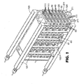
図1を参照すると、本発明の実施に有用な燃料電池スタックは、燃料電池モジュール(20)と交互に積重ねられた冷却プレート(10)を含む。燃料電池モジュール(20)は、少なくとも1つの膜電極アセンブリ(MEA)(30)を含み、2つ以上のMEA(30)を収容してもよい。MEA(30)は、分配プレート(40)と交互に挟まれて、燃料電池モジュール(20)を形成する。冷却プレート(10)は、任意の適切な材料から製造してもよい。冷却プレート(10)は、典型的には、金属またはめっき金属材料などの熱伝導性材料から製造される。典型的には、冷却プレートは、導電性材料から製造される。付加的な考慮事項は、重量、コスト、および製造性を含む。典型的には、冷却プレートはアルミニウムである。冷却プレート(10)は、典型的にはプレートの両側に、入口および出口を有する液体冷却チャネル(111)を含む。冷却チャネルは、円形、矩形、楕円形などの任意の適切な断面形状を有してもよい。典型的には、燃料電池モジュール(20)は、各MEA(30)が少なくとも1つの冷却プレート(10)に隣接するように、1つまたは2つのMEA(30)を含む。 Referring to FIG. 1, a fuel cell stack useful in the practice of the present invention includes cooling plates (10) alternately stacked with fuel cell modules (20). The fuel cell module (20) includes at least one membrane electrode assembly (MEA) (30) and may contain more than one MEA (30). The MEA (30) is alternately sandwiched with the distribution plate (40) to form the fuel cell module (20). The cooling plate (10) may be manufactured from any suitable material. The cooling plate (10) is typically manufactured from a thermally conductive material, such as a metal or plated metal material. Typically, the cooling plate is manufactured from a conductive material. Additional considerations include weight, cost, and manufacturability. Typically, the cooling plate is aluminum. The cooling plate (10) typically includes a liquid cooling channel (111) having an inlet and an outlet on either side of the plate. The cooling channel may have any suitable cross-sectional shape such as circular, rectangular, elliptical. Typically, the fuel cell module (20) includes one or two MEAs (30) such that each MEA (30) is adjacent to at least one cooling plate (10).
冷却プレート(10)は、外部マニホルド(121、122、123、124)と相互作用するように構成された入口および出口を含んでもよく、反応物流体または生成物流体を、分配プレート(40)におよび分配プレート(40)から送出し、分配プレート(40)は、反応物流体または生成物流体を、MEA(30)におよびMEA(30)から送出する。したがって、入口および出口は、前記分配プレートへのおよび/または前記分配プレートからの流体の輸送のための反応物/生成物経路を構成する。冷却プレート(10)の入口および出口は、Oリングシールを介して、分配プレート(40)のポートと相互作用してもよい。入口および出口が、冷却プレート(10)の材料に対して腐食性を有する流体を搬送する場合もあるので、入口および出口は、それらの内面上に耐腐食性コーティングを有してもよいし、冷却プレートの材料以外の材料、典型的には、ポリエーテルエーテルケトン(PEEK)ポリマーを含んでもよい、中に輸送される反応物または生成物に対して不活性の材料を含むインサートピースを取付けてもよい。あるいは、反応物/生成物マニホルドが燃料電池スタックの内部に配置されてもよい。内部マニホルディングの場合、各マニホルドは、連続した燃料電池モジュール(20)および冷却プレート(10)を通る一連の一致する開口部を、典型的には各プレートまたはモジュールの平面に直交する方向に含む。典型的には、Oリングまたは他のシールが、燃料電池モジュール(20)と冷却プレート(10)との間に配置されて、シールされたマニホルド経路を形成する。反応物および生成物マニホルドは、分配プレート(40)の適切なチャネル内に開口する、各燃料電池モジュール(20)の経路と連通する。 The cooling plate (10) may include an inlet and an outlet configured to interact with the external manifold (121, 122, 123, 124) to pass the reactant fluid or product fluid to the distribution plate (40). And dispense plate (40), which distributes reactant fluid or product fluid to and from MEA (30). Thus, the inlet and outlet constitute a reactant / product pathway for transport of fluid to and / or from the distribution plate. The inlet and outlet of the cooling plate (10) may interact with the ports of the distribution plate (40) via O-ring seals. Since the inlet and outlet may carry fluids that are corrosive to the material of the cooling plate (10), the inlet and outlet may have a corrosion resistant coating on their inner surface, Attaching an insert piece containing a material other than the material of the cooling plate, typically a material that is inert to the reactants or products being transported therein, which may include a polyetheretherketone (PEEK) polymer. Also good. Alternatively, the reactant / product manifold may be placed inside the fuel cell stack. For internal manifolding, each manifold includes a series of matching openings through successive fuel cell modules (20) and cooling plates (10), typically in a direction perpendicular to the plane of each plate or module. . Typically, an O-ring or other seal is placed between the fuel cell module (20) and the cooling plate (10) to form a sealed manifold path. The reactants and product manifolds communicate with the path of each fuel cell module (20) that opens into the appropriate channel of the distribution plate (40).
図1は、本明細書と同日に出願された同時係属中の特許出願第10/295,518号明細書に記載されているような、冷却プレートが圧縮プレートを兼ねるシステムを示す。対の圧縮プレート(10)が、ボルト(60、61)によって所定位置に保持されたラッチ(50)を含む機械的リンクによって接合される。ラッチ(50)は、燃料電池モジュール(20)の短絡を回避するように、非導電性でなければならず、典型的には、ポリエーテルエーテルケトン(PEEK)などの強いポリマー不導体を含む。 FIG. 1 shows a system in which a cooling plate doubles as a compression plate, as described in copending patent application Ser. No. 10 / 295,518, filed on the same date as the present specification. A pair of compression plates (10) are joined by a mechanical link including a latch (50) held in place by bolts (60, 61). The latch (50) must be non-conductive to avoid short circuiting of the fuel cell module (20) and typically includes a strong polymer non-conductor such as polyetheretherketone (PEEK).
図2および図3を参照すると、本発明の実施に有用な流体送出機構は、マニホルドボックス(200、201、202)を含む。示されたマニホルドボックスは、本体(200)と、スクリュ穴(205)を通してスクリュによってガスケット(202)とともに本体に接合されたカバー(201)とを含む。マニホルドボックスは、マニホルドボックスおよび冷却プレート(図1を参照)のスクリュ穴(210、211)を通してスクリュによってスタックに接合してもよい。マニホルドボックス本体(200)は、非導電性材料から製造しなければならないか、スタックから電気的に絶縁しなければならず、そうでなければ、燃料電池モジュールの短絡が生じる。マニホルドボックス出口(220)が、冷却プレート(図1を参照)の冷却チャネル(111)の入口と連通する。冷却流体ポンプに連結するホースまたはパイプなどの冷却流体の外部源が、マニホルドボックス入口(230)に連結する。ディフューザ(240)が、マニホルドボックス内に位置決めされる。ディフューザ(240)は、マニホルドボックス入口(230)への液体冷却剤のすべての流れを受けるようにマニホルドボックス入口(230)と連通するディフューザ入口(250)を有する。ディフューザ(240)は、その長さに沿って分配された複数のディフューザ出口(260)を有する。実質的に均一な冷却剤流体圧力がディフューザの外側のマニホルドボックス内で維持されるように、ディフューザ出口(260)の任意の適切な分配を用いてもよい。典型的には、ディフューザ出口(260)は、マニホルドボックス出口(220)の位置に対して一様に分配され、したがって、冷却プレート(図1を参照のこと)の冷却チャネル(111)の位置に対して一様に分配される。典型的には、ディフューザ出口(260)は、流れ方向に垂直に、ディフューザ(240)内にカットされる。ディフューザ(240)は、その遠い端部で閉じている。あるいは、ディフューザは、ディフューザの外側のマニホルドボックス内で実質的に均一な冷却剤流体圧力を維持することができる、メッシュ、布、または他の浸透性構造を含んでもよい。 With reference to FIGS. 2 and 3, a fluid delivery mechanism useful in the practice of the present invention includes a manifold box (200, 201, 202). The illustrated manifold box includes a body (200) and a cover (201) joined to the body with a gasket (202) by a screw through a screw hole (205). The manifold box may be joined to the stack by screws through screw holes (210, 211) in the manifold box and cooling plate (see FIG. 1). The manifold box body (200) must be manufactured from a non-conductive material or must be electrically isolated from the stack, otherwise a short circuit of the fuel cell module will occur. A manifold box outlet (220) communicates with the inlet of the cooling channel (111) of the cooling plate (see FIG. 1). An external source of cooling fluid, such as a hose or pipe that connects to a cooling fluid pump, connects to the manifold box inlet (230). A diffuser (240) is positioned in the manifold box. The diffuser (240) has a diffuser inlet (250) in communication with the manifold box inlet (230) to receive all flow of liquid coolant to the manifold box inlet (230). The diffuser (240) has a plurality of diffuser outlets (260) distributed along its length. Any suitable distribution of the diffuser outlet (260) may be used so that a substantially uniform coolant fluid pressure is maintained in the manifold box outside the diffuser. Typically, the diffuser outlet (260) is evenly distributed with respect to the position of the manifold box outlet (220) and is therefore at the position of the cooling channel (111) of the cooling plate (see FIG. 1). Are uniformly distributed. Typically, the diffuser outlet (260) is cut into the diffuser (240) perpendicular to the flow direction. The diffuser (240) is closed at its far end. Alternatively, the diffuser may include a mesh, cloth, or other permeable structure that can maintain a substantially uniform coolant fluid pressure within the manifold box outside the diffuser.
図2および図3に示された本発明の一実施形態において、マニホルドボックス(200、201、202)は、2つのチャンバ、すなわち、入口チャンバ(270)および出口チャンバ(280)に分けられる。入口チャンバ(270)は、上述のように機能する。出口チャンバ(280)は、マニホルドボックス収集口(281)を介して冷却プレート(図1を参照)の冷却チャネル(111)の出口と連通し、冷却流体が、マニホルドボックス出口(282)を通って、典型的には冷却流体の外部溜めまたは冷却流体ポンプへのホースまたはパイプを介して、出ることを可能にする。出口チャンバ(280)にディフューザは必要ない。第1の複数の冷却チャネルが、冷却プレートの第1の面上の冷却チャネル入口と、冷却プレートの第2の面上の冷却チャネル出口とを有し、第2の複数の冷却チャネルが、第2の面上の入口と、第1の面上の出口とを有するので、スタックの各側で2チャンバマニホルドボックスを使用することは、スタックの互いに反対側のチャネルを通って互いに反対方向に移動する冷却剤の向流を生じさせる。実際には、第1の複数の冷却チャネルの冷却チャネル入口、第1の複数の冷却チャネルの冷却チャネル出口、第2の複数の冷却チャネルの冷却チャネル入口、および第2の複数の冷却チャネルの冷却チャネル出口の各々に供給するために、4つのマニホルドが設けられる。結果として生じる向流を用いて、スタック全体にわたって温度の均一性を向上させてもよい。 In one embodiment of the invention shown in FIGS. 2 and 3, the manifold box (200, 201, 202) is divided into two chambers: an inlet chamber (270) and an outlet chamber (280). The inlet chamber (270) functions as described above. The outlet chamber (280) communicates with the outlet of the cooling channel (111) of the cooling plate (see FIG. 1) via the manifold box collection port (281), and the cooling fluid passes through the manifold box outlet (282). , Typically through an external reservoir of cooling fluid or a hose or pipe to a cooling fluid pump. No diffuser is required in the outlet chamber (280). The first plurality of cooling channels has a cooling channel inlet on the first side of the cooling plate and a cooling channel outlet on the second side of the cooling plate, the second plurality of cooling channels being Having an inlet on the two sides and an outlet on the first side, using a two-chamber manifold box on each side of the stack moves in opposite directions through channels on opposite sides of the stack Causing countercurrent flow of coolant. In practice, the cooling channel inlet of the first plurality of cooling channels, the cooling channel outlet of the first plurality of cooling channels, the cooling channel inlet of the second plurality of cooling channels, and the cooling of the second plurality of cooling channels Four manifolds are provided to feed each of the channel outlets. The resulting countercurrent may be used to improve temperature uniformity across the stack.
本発明の実施において、スタックは、典型的には、スタックの外側部分および内側部分が同様の温度で維持されるように、熱絶縁材料で巻かれる。ガラス繊維絶縁体などの任意の適切な熱絶縁材料を使用してもよい。熱絶縁材料のR値は、典型的には少なくとも3、より典型的には少なくとも5、より典型的には少なくとも8である。スタックは、典型的には、少なくとも2つの側の実質的にすべてにおいて絶縁され、より典型的には、4つの側の実質的にすべてにおいて絶縁される。 In the practice of the present invention, the stack is typically wrapped with a thermally insulating material so that the outer and inner portions of the stack are maintained at similar temperatures. Any suitable thermally insulating material such as a glass fiber insulator may be used. The R value of the thermally insulating material is typically at least 3, more typically at least 5, and more typically at least 8. The stack is typically insulated on substantially all of at least two sides, and more typically is insulated on substantially all four sides.
本発明は、燃料電池スタックおよびシステムの設計、製造、および動作に有用である。 The present invention is useful for the design, manufacture, and operation of fuel cell stacks and systems.
本発明の目的および利点を、次の実施例によってさらに例示するが、これらの実施例に記載された特定の材料およびそれらの量、ならびに他の条件および詳細は、本発明を不当に限定するように解釈されるべきではない。 The objects and advantages of the present invention are further illustrated by the following examples, but the specific materials and their amounts described in these examples, as well as other conditions and details, may unduly limit the present invention. Should not be interpreted.
図1に実質的に従う燃料電池スタックに、ディフューザ(240)を使用して、ディフューザ(240)を使用せずに、図2および図3に実質的に従うマニホルドボックスを取付けた。両方のケースにおいて、スタックをガラス繊維絶縁材料で巻いた。図4は、ディフューザ(トレースA)のケースおよびディフューザのない(比較のためのトレースB)ケースにおける、さまざまな電力レベルで測定された最も上の冷却プレートと最も下の冷却プレートとの間の測定温度の差を報告する。冷却剤流量が、ディフューザを使用した場合4.5L/分であり、ディフューザを使用しなかった場合3.1L/分であった以外は、すべての変数は各ランにおいて同一であった。 A fuel cell stack substantially according to FIG. 1 was fitted with a manifold box substantially according to FIGS. 2 and 3 using the diffuser (240) and without the diffuser (240). In both cases, the stack was wound with glass fiber insulation material. FIG. 4 shows the measurement between the top and bottom cooling plates measured at various power levels in the case of the diffuser (trace A) and the case without the diffuser (trace B for comparison). Report the temperature difference. All variables were the same in each run except that the coolant flow rate was 4.5 L / min with the diffuser and 3.1 L / min without the diffuser.
本発明のさまざまな修正および変更が、本発明の範囲および原理から逸脱することなく、当業者には明らかになるであろう。また、本発明は、上述された例示的な実施形態に不当に限定されるべきではないことが理解されるべきである。 Various modifications and alterations of this invention will become apparent to those skilled in the art without departing from the scope and principles of this invention. It should also be understood that the present invention should not be unduly limited to the exemplary embodiments described above.
Claims (20)
各々が複数の冷却チャネルを含む1つ以上の冷却プレートであって、前記冷却チャネルの各々が冷却チャネル入口と冷却チャネル出口とを有する、冷却プレートと、
第1のマニホルドボックス入口を有し、かつ1つ以上の第1のマニホルドボックス出口を介して冷却チャネル入口と連通する第1のマニホルドボックスと、
a)前記第1のマニホルドボックス入口への液体冷却剤のすべての流れを受けるように前記第1のマニホルドボックス入口と連通する第1のディフューザ入口、及びb)複数の第1のディフューザ出口を有する、前記第1のマニホルドボックス内に位置決めされた第1のディフューザと、
を含む、液体冷却式燃料電池スタックであって、
実質的に均一な冷却剤流体圧力が、前記第1のディフューザの外側の前記第1のマニホルドボックス内で維持される、液体冷却式燃料電池スタック。 One or more fuel cell modules, each including at least one membrane electrode assembly;
One or more cooling plates each including a plurality of cooling channels, each cooling channel having a cooling channel inlet and a cooling channel outlet;
A first manifold box having a first manifold box inlet and in communication with the cooling channel inlet via one or more first manifold box outlets;
a) a first diffuser inlet in communication with the first manifold box inlet to receive all flow of liquid coolant to the first manifold box inlet; and b) a plurality of first diffuser outlets. A first diffuser positioned in the first manifold box;
A liquid-cooled fuel cell stack comprising
A liquid cooled fuel cell stack, wherein a substantially uniform coolant fluid pressure is maintained in the first manifold box outside the first diffuser.
各々が複数の冷却チャネルを含む1つ以上の冷却プレートであって、前記冷却チャネルの各々が冷却チャネル入口と冷却チャネル出口とを有する、冷却プレートと、
第1のマニホルドボックス入口を有し、かつ1つ以上の第1のマニホルドボックス出口を介して冷却チャネル入口と連通する第1のマニホルドボックスと、
a)前記第1のマニホルドボックス入口への液体冷却剤のすべての流れを受けるように前記第1のマニホルドボックス入口と連通する第1のディフューザ入口、及びb)前記冷却チャネル入口に対して一様に分配された複数の第1のディフューザ出口を有する、前記第1のマニホルドボックス内に位置決めされた第1のディフューザと、
を含む、液体冷却式燃料電池スタック。 One or more fuel cell modules, each including at least one membrane electrode assembly;
One or more cooling plates each including a plurality of cooling channels, each cooling channel having a cooling channel inlet and a cooling channel outlet;
A first manifold box having a first manifold box inlet and in communication with the cooling channel inlet via one or more first manifold box outlets;
a) a first diffuser inlet in communication with the first manifold box inlet to receive all flow of liquid coolant to the first manifold box inlet; and b) uniform with respect to the cooling channel inlet. A first diffuser positioned in the first manifold box, having a plurality of first diffuser outlets distributed to the first manifold box;
Including a liquid-cooled fuel cell stack.
Applications Claiming Priority (2)
| Application Number | Priority Date | Filing Date | Title |
|---|---|---|---|
| US10/294,074 US20040096715A1 (en) | 2002-11-14 | 2002-11-14 | Liquid cooled fuel cell stack |
| PCT/US2003/027560 WO2004045013A2 (en) | 2002-11-14 | 2003-09-03 | Liquid cooled fuel cell stack |
Publications (2)
| Publication Number | Publication Date |
|---|---|
| JP2006506778A true JP2006506778A (en) | 2006-02-23 |
| JP2006506778A5 JP2006506778A5 (en) | 2006-10-26 |
Family
ID=32296893
Family Applications (1)
| Application Number | Title | Priority Date | Filing Date |
|---|---|---|---|
| JP2004551453A Pending JP2006506778A (en) | 2002-11-14 | 2003-09-03 | Liquid-cooled fuel cell stack |
Country Status (10)
| Country | Link |
|---|---|
| US (1) | US20040096715A1 (en) |
| EP (1) | EP1573844B1 (en) |
| JP (1) | JP2006506778A (en) |
| KR (1) | KR20050074611A (en) |
| CN (1) | CN100533832C (en) |
| AT (1) | ATE451730T1 (en) |
| AU (1) | AU2003268403A1 (en) |
| CA (1) | CA2505830A1 (en) |
| DE (1) | DE60330500D1 (en) |
| WO (1) | WO2004045013A2 (en) |
Cited By (1)
| Publication number | Priority date | Publication date | Assignee | Title |
|---|---|---|---|---|
| JP2014183010A (en) * | 2013-03-21 | 2014-09-29 | Osaka Gas Co Ltd | Solid polymer fuel cell |
Families Citing this family (13)
| Publication number | Priority date | Publication date | Assignee | Title |
|---|---|---|---|---|
| US7026065B2 (en) * | 2001-08-31 | 2006-04-11 | Plug Power Inc. | Fuel cell system heat recovery |
| US7687176B2 (en) | 2004-12-10 | 2010-03-30 | 3M Innovative Properties Company | Fuel cell |
| KR101191497B1 (en) * | 2007-12-26 | 2012-10-15 | 유티씨 파워 코포레이션 | Fuel cell and bipolar plate for limiting leakage |
| US8465863B2 (en) | 2008-04-09 | 2013-06-18 | GM Global Technology Operations LLC | Batteries and components thereof and methods of making and assembling the same |
| US8486552B2 (en) * | 2008-06-30 | 2013-07-16 | Lg Chem, Ltd. | Battery module having cooling manifold with ported screws and method for cooling the battery module |
| WO2010082589A1 (en) * | 2009-01-16 | 2010-07-22 | 本田技研工業株式会社 | Fuel cell stack |
| DE102009040197A1 (en) | 2009-09-07 | 2011-03-10 | Behr Gmbh & Co. Kg | Modular battery construction |
| KR101240976B1 (en) * | 2010-11-12 | 2013-03-11 | 현대자동차주식회사 | Refrigerant system of fuel cell for vehicle |
| KR101807378B1 (en) * | 2012-11-09 | 2017-12-08 | 유나이티드 테크놀로지스 코포레이션 | Electrochemical device and method for controlling corrosion |
| US20170104251A1 (en) * | 2015-10-13 | 2017-04-13 | Ford Global Technologies, Llc | Battery pack retention device and method |
| DE102018115919A1 (en) * | 2018-07-02 | 2020-01-02 | Audi Aktiengesellschaft | Traction battery of a motor vehicle |
| DE102019214744A1 (en) * | 2019-06-28 | 2020-12-31 | Mahle International Gmbh | Traction battery |
| CN112952155B (en) * | 2021-05-11 | 2022-02-18 | 北京亿华通科技股份有限公司 | Flow guide structure and fuel cell system |
Citations (9)
| Publication number | Priority date | Publication date | Assignee | Title |
|---|---|---|---|---|
| JPS61148768A (en) * | 1984-12-21 | 1986-07-07 | Toshiba Corp | Fused carbonate type fuel cell |
| JPS6266574A (en) * | 1985-09-19 | 1987-03-26 | Fuji Electric Co Ltd | Air cooling type fuel cell |
| JPS6316576A (en) * | 1986-07-07 | 1988-01-23 | Fuji Electric Co Ltd | Air cooling type fuel cell |
| JPH05190193A (en) * | 1992-01-17 | 1993-07-30 | Fuji Electric Co Ltd | Solid high polymeric electrolyte type fuel cell |
| JPH07326378A (en) * | 1994-05-31 | 1995-12-12 | Toshiba Corp | Fuel cell |
| JPH09161828A (en) * | 1995-12-14 | 1997-06-20 | Sanyo Electric Co Ltd | Fuel cell |
| JPH10223238A (en) * | 1997-02-05 | 1998-08-21 | Mitsubishi Electric Corp | Solid polymer electrolyte fuel cell laminate, and manufacture of gas separation plate of the same |
| JP2001015138A (en) * | 1999-06-30 | 2001-01-19 | Fuji Electric Co Ltd | Solid polymer type fuel cell |
| JP2002252021A (en) * | 2001-02-23 | 2002-09-06 | Sanyo Electric Co Ltd | Fuel cell |
Family Cites Families (29)
| Publication number | Priority date | Publication date | Assignee | Title |
|---|---|---|---|---|
| JPS5897272A (en) * | 1981-12-02 | 1983-06-09 | Hitachi Ltd | Fuel cell |
| US4430390A (en) * | 1982-09-23 | 1984-02-07 | Engelhard Corporation | Compact fuel cell stack |
| US4574112A (en) * | 1983-12-23 | 1986-03-04 | United Technologies Corporation | Cooling system for electrochemical fuel cell |
| JPS60113955U (en) * | 1984-01-10 | 1985-08-01 | 株式会社 富士電機総合研究所 | Fuel cell |
| US5041344A (en) * | 1984-12-14 | 1991-08-20 | Fuji Electric Corporate Research And Development Ltd. | Fuel cell cooling device |
| US4706737A (en) * | 1986-11-20 | 1987-11-17 | International Fuel Cells Corporation | Fuel cell coolant inlet manifold and system |
| JPH07105241B2 (en) * | 1987-11-10 | 1995-11-13 | 富士電機株式会社 | Fuel cell manifold |
| EP0444383B1 (en) * | 1990-03-01 | 1995-01-04 | Tanaka Kikinzoku Kogyo K.K. | Structure for incorporating a fuel cell |
| US5364711A (en) * | 1992-04-01 | 1994-11-15 | Kabushiki Kaisha Toshiba | Fuel cell |
| US5686200A (en) * | 1993-12-22 | 1997-11-11 | Ballard Power Systems Inc. | Electrochemical fuel cell assembly with compliant compression mechanism |
| KR0123727B1 (en) * | 1994-08-17 | 1997-12-09 | 김광호 | Stack for fuel cell |
| EP0698936B1 (en) * | 1994-08-23 | 1998-03-11 | Osaka Gas Co., Ltd. | Fuel cell system |
| US5607786A (en) * | 1995-05-05 | 1997-03-04 | International Fuel Cells Corporation | Fuel cell transport frame |
| ATE301335T1 (en) * | 1995-05-25 | 2005-08-15 | Honda Motor Co Ltd | FUEL CELL AND METHOD FOR CONTROL THEREOF |
| US5962155A (en) * | 1996-01-22 | 1999-10-05 | Matsushita Electric Industrial Co., Ltd. | Fuel cell system |
| US5789091C1 (en) * | 1996-11-19 | 2001-02-27 | Ballard Power Systems | Electrochemical fuel cell stack with compression bands |
| DE19649691C2 (en) * | 1996-11-29 | 1998-10-15 | Siemens Ag | Liquid-cooled fuel cell battery and method for cooling it |
| US5998054A (en) * | 1997-07-23 | 1999-12-07 | Plug Power, L.L.C. | Fuel cell membrane hydration and fluid metering |
| US6030718A (en) * | 1997-11-20 | 2000-02-29 | Avista Corporation | Proton exchange membrane fuel cell power system |
| US6057053A (en) * | 1997-11-25 | 2000-05-02 | Ballard Power Systems Inc. | Compression assembly for an electrochemical fuel cell stack |
| US5935726A (en) * | 1997-12-01 | 1999-08-10 | Ballard Power Systems Inc. | Method and apparatus for distributing water to an ion-exchange membrane in a fuel cell |
| JP4031860B2 (en) * | 1998-02-17 | 2008-01-09 | 本田技研工業株式会社 | Fuel cell having a clamping structure |
| GB9809372D0 (en) * | 1998-05-02 | 1998-07-01 | British Gas Plc | Stack assembly primarily for an electrochemical fuel |
| EP0981175B1 (en) * | 1998-08-20 | 2012-05-02 | Panasonic Corporation | Polymer electrolyte fuel cell stack |
| JP4220615B2 (en) * | 1999-04-16 | 2009-02-04 | 三菱重工業株式会社 | Fuel cell stack |
| US6322919B1 (en) * | 1999-08-16 | 2001-11-27 | Alliedsignal Inc. | Fuel cell and bipolar plate for use with same |
| US6218039B1 (en) * | 1999-08-25 | 2001-04-17 | Plug Power, Inc. | Clamping apparatus and method for a fuel cell |
| DE10040792C2 (en) * | 2000-08-21 | 2003-04-10 | Proton Motor Fuel Cell Gmbh | Polymer electrolyte membrane fuel cell system with cooling medium distribution space and collecting space and with cooling by fluid media |
| US6596427B1 (en) * | 2000-11-06 | 2003-07-22 | Ballard Power Systems Inc. | Encapsulating seals for electrochemical cell stacks and methods of sealing electrochemical cell stacks |
-
2002
- 2002-11-14 US US10/294,074 patent/US20040096715A1/en not_active Abandoned
-
2003
- 2003-09-03 DE DE60330500T patent/DE60330500D1/en not_active Expired - Lifetime
- 2003-09-03 EP EP03749367A patent/EP1573844B1/en not_active Expired - Lifetime
- 2003-09-03 WO PCT/US2003/027560 patent/WO2004045013A2/en active Application Filing
- 2003-09-03 JP JP2004551453A patent/JP2006506778A/en active Pending
- 2003-09-03 AU AU2003268403A patent/AU2003268403A1/en not_active Abandoned
- 2003-09-03 AT AT03749367T patent/ATE451730T1/en not_active IP Right Cessation
- 2003-09-03 KR KR1020057008559A patent/KR20050074611A/en not_active Application Discontinuation
- 2003-09-03 CN CNB038250799A patent/CN100533832C/en not_active Expired - Fee Related
- 2003-09-03 CA CA002505830A patent/CA2505830A1/en not_active Abandoned
Patent Citations (9)
| Publication number | Priority date | Publication date | Assignee | Title |
|---|---|---|---|---|
| JPS61148768A (en) * | 1984-12-21 | 1986-07-07 | Toshiba Corp | Fused carbonate type fuel cell |
| JPS6266574A (en) * | 1985-09-19 | 1987-03-26 | Fuji Electric Co Ltd | Air cooling type fuel cell |
| JPS6316576A (en) * | 1986-07-07 | 1988-01-23 | Fuji Electric Co Ltd | Air cooling type fuel cell |
| JPH05190193A (en) * | 1992-01-17 | 1993-07-30 | Fuji Electric Co Ltd | Solid high polymeric electrolyte type fuel cell |
| JPH07326378A (en) * | 1994-05-31 | 1995-12-12 | Toshiba Corp | Fuel cell |
| JPH09161828A (en) * | 1995-12-14 | 1997-06-20 | Sanyo Electric Co Ltd | Fuel cell |
| JPH10223238A (en) * | 1997-02-05 | 1998-08-21 | Mitsubishi Electric Corp | Solid polymer electrolyte fuel cell laminate, and manufacture of gas separation plate of the same |
| JP2001015138A (en) * | 1999-06-30 | 2001-01-19 | Fuji Electric Co Ltd | Solid polymer type fuel cell |
| JP2002252021A (en) * | 2001-02-23 | 2002-09-06 | Sanyo Electric Co Ltd | Fuel cell |
Cited By (1)
| Publication number | Priority date | Publication date | Assignee | Title |
|---|---|---|---|---|
| JP2014183010A (en) * | 2013-03-21 | 2014-09-29 | Osaka Gas Co Ltd | Solid polymer fuel cell |
Also Published As
| Publication number | Publication date |
|---|---|
| CA2505830A1 (en) | 2004-05-27 |
| EP1573844B1 (en) | 2009-12-09 |
| CN100533832C (en) | 2009-08-26 |
| ATE451730T1 (en) | 2009-12-15 |
| WO2004045013A2 (en) | 2004-05-27 |
| US20040096715A1 (en) | 2004-05-20 |
| CN101027809A (en) | 2007-08-29 |
| EP1573844A2 (en) | 2005-09-14 |
| AU2003268403A1 (en) | 2004-06-03 |
| DE60330500D1 (en) | 2010-01-21 |
| WO2004045013A3 (en) | 2005-07-28 |
| KR20050074611A (en) | 2005-07-18 |
Similar Documents
| Publication | Publication Date | Title |
|---|---|---|
| US5858569A (en) | Low cost fuel cell stack design | |
| US6322919B1 (en) | Fuel cell and bipolar plate for use with same | |
| CA2374293C (en) | Fuel cell stack assembly | |
| US8865362B2 (en) | Gaskets and bipolar plates for PEM fuel cells | |
| US8580457B2 (en) | Fuel cell stack sealed with encapsulating material and method of making the same | |
| US20050115825A1 (en) | Electrolyzer cell arrangement | |
| EP1573844B1 (en) | Liquid cooled fuel cell stack | |
| JP3920018B2 (en) | Fuel cell stack | |
| WO2006022994A2 (en) | Isolated and insulated stack end unit inlet/outlet manifold headers | |
| US8124292B2 (en) | Fuel cell stacks and methods | |
| KR20040050872A (en) | Methods and apparatus for assembling solid oxide fuel cells | |
| US7432008B2 (en) | Gas diffusion layer for an electrochemical cell | |
| US20040023089A1 (en) | Polymer electrolyte membrane fuel cell system comprising a cooling medium distribution space and cooling medium collection space, and with cooling effected by fluidic media | |
| EP2168185B1 (en) | Fuel cell stacks and methods | |
| CN1326279C (en) | Polymer electrolyte fuel cell | |
| KR101061395B1 (en) | Fuel cell cooled and humidified by evaporation | |
| CN211929634U (en) | Interface plate for fuel cell | |
| JPH08162145A (en) | Solid polymer electrolytic fuel cell | |
| KR102278869B1 (en) | New modular electrochemical cell and stack design | |
| JP2019012705A (en) | Fuel cell stack | |
| JP2001135342A (en) | High molecular electrolyte fuel cell |
Legal Events
| Date | Code | Title | Description |
|---|---|---|---|
| A521 | Request for written amendment filed |
Free format text: JAPANESE INTERMEDIATE CODE: A523 Effective date: 20060831 |
|
| A621 | Written request for application examination |
Free format text: JAPANESE INTERMEDIATE CODE: A621 Effective date: 20060831 |
|
| A131 | Notification of reasons for refusal |
Free format text: JAPANESE INTERMEDIATE CODE: A131 Effective date: 20100608 |
|
| A601 | Written request for extension of time |
Free format text: JAPANESE INTERMEDIATE CODE: A601 Effective date: 20100907 |
|
| A602 | Written permission of extension of time |
Free format text: JAPANESE INTERMEDIATE CODE: A602 Effective date: 20100914 |
|
| A02 | Decision of refusal |
Free format text: JAPANESE INTERMEDIATE CODE: A02 Effective date: 20110215 |